EP4206106A1 - Method and device for detecting elevator safety chain - Google Patents
Method and device for detecting elevator safety chain Download PDFInfo
- Publication number
- EP4206106A1 EP4206106A1 EP22208168.9A EP22208168A EP4206106A1 EP 4206106 A1 EP4206106 A1 EP 4206106A1 EP 22208168 A EP22208168 A EP 22208168A EP 4206106 A1 EP4206106 A1 EP 4206106A1
- Authority
- EP
- European Patent Office
- Prior art keywords
- safety chain
- level
- elevator safety
- operating signal
- landing door
- Prior art date
- Legal status (The legal status is an assumption and is not a legal conclusion. Google has not performed a legal analysis and makes no representation as to the accuracy of the status listed.)
- Granted
Links
Images




Classifications
-
- B—PERFORMING OPERATIONS; TRANSPORTING
- B66—HOISTING; LIFTING; HAULING
- B66B—ELEVATORS; ESCALATORS OR MOVING WALKWAYS
- B66B13/00—Doors, gates, or other apparatus controlling access to, or exit from, cages or lift well landings
- B66B13/22—Operation of door or gate contacts
-
- B—PERFORMING OPERATIONS; TRANSPORTING
- B66—HOISTING; LIFTING; HAULING
- B66B—ELEVATORS; ESCALATORS OR MOVING WALKWAYS
- B66B5/00—Applications of checking, fault-correcting, or safety devices in elevators
- B66B5/0006—Monitoring devices or performance analysers
- B66B5/0037—Performance analysers
-
- B—PERFORMING OPERATIONS; TRANSPORTING
- B66—HOISTING; LIFTING; HAULING
- B66B—ELEVATORS; ESCALATORS OR MOVING WALKWAYS
- B66B5/00—Applications of checking, fault-correcting, or safety devices in elevators
- B66B5/0006—Monitoring devices or performance analysers
- B66B5/0018—Devices monitoring the operating condition of the elevator system
- B66B5/0031—Devices monitoring the operating condition of the elevator system for safety reasons
-
- B—PERFORMING OPERATIONS; TRANSPORTING
- B66—HOISTING; LIFTING; HAULING
- B66B—ELEVATORS; ESCALATORS OR MOVING WALKWAYS
- B66B5/00—Applications of checking, fault-correcting, or safety devices in elevators
- B66B5/0087—Devices facilitating maintenance, repair or inspection tasks
- B66B5/0093—Testing of safety devices
-
- B—PERFORMING OPERATIONS; TRANSPORTING
- B66—HOISTING; LIFTING; HAULING
- B66B—ELEVATORS; ESCALATORS OR MOVING WALKWAYS
- B66B3/00—Applications of devices for indicating or signalling operating conditions of elevators
Definitions
- the present application relates to elevator technology, in particular to a method and device for detecting an elevator safety chain and a computer-readable storage medium for implementing the method.
- An elevator system usually includes multiple door interlocks, each installed on the corresponding landing door and including a landing door switch for detecting the locking state and unlocking state of the door interlock. These landing door switches are connected in series with each other, and an operating signal indicating the closed state of all door switches during elevator operation is sent to an elevator control device to correctly operate an elevator car.
- a device for detecting an elevator safety chain comprising:
- the time domain characteristic includes the characteristic that an amplitude of the operating signal changes with time.
- the running of the computer program causes the reliability of the elevator safety chain to be evaluated in the following manner:
- width of the time window is determined based on operation parameters of a landing door.
- the width is determined to be substantially equal to a predetermined duration that the landing door remains open when no passengers are entering an elevator car or a predicted duration that the landing door remains open when a passenger is entering the elevator car.
- the running of the computer program causes the reliability of the elevator safety chain to be evaluated in the following manner:
- the second threshold is determined to be substantially equal to a predetermined duration that the landing door remains open when no passengers are entering an elevator car or a predicted duration that the landing door remains open when a passenger is entering the elevator car.
- the running of the computer program causes the reliability of the elevator safety chain to be evaluated in the following manner:
- the interface unit includes an AC-DC conversion circuit configured to convert an AC signal transmitted on the elevator safety chain into the operating signal having the first level.
- the interface unit includes a DC-DC conversion circuit configured to convert a DC signal transmitted on the elevator safety chain into the operating signal having the first level.
- the device is an elevator controller.
- the running of the computer program causes an evaluation result on the reliability of the elevator safety chain to be output.
- a method for detecting an elevator safety chain which is characterized in that it comprises the following steps:
- a computer-readable storage medium having instructions stored in the computer-readable storage medium, when the instructions are executed by a microcontroller, the microcontroller is caused to execute the above method.
- first and second do not indicate the order of the units in terms of time, space, size, etc., but are merely used to distinguish the units.
- Fig. 1 is a schematic diagram of a typical elevator safety chain.
- An elevator safety chain 10 shown in Fig. 1 includes landing door switches k1-kn connected in series with each other, each installed on their respective landing doors.
- the elevator safety chain 10 and a detection device 20 for detecting the elevator safety chain are connected in series between a power supply (such as 110V AC) and a ground. Under normal circumstances, when the landing doors are all closed, the landing door switches k1-kn in the elevator safety chain 10 are all closed.
- an operating signal having a first level (such as a high-level signal) will be generated at the detection device 20; on the other hand, when one of the landing doors is opened, the corresponding landing door switch in the elevator safety chain 10 will be in an opened state, and an operating signal having a second level (such as a low-level signal) will be generated at the detection device 20 at this time.
- a first level such as a high-level signal
- a second level such as a low-level signal
- deterioration of the landing door switch performance is a gradual process over time, that is, in the early stage, the landing door switch only occasionally misoperates, and it will eventually evolve into permanent failure over time.
- the inventors of the present application also found that, in terms of time domain characteristic, there is a significant difference between the operating signal generated on the detection device side due to the deterioration of the performance of the landing door switch and the operating signal generated on the detection device side by the landing door switch in response to an elevator control command (or the opening and closing of the landing door). Due to the existence of this difference, the hidden danger of the failure of the landing door switch may be found in time through the detection and analysis of the operating signal, which is particularly conducive to reducing the workload of elevator maintenance.
- Figs. 2A-2D show various waveforms of operating signals reflecting states of the elevator safety chain.
- Fig. 2A is the waveform of the signal generated by the landing door switch on the detection device side in response to the opening and closing of the landing door
- Figs. 2B-2C are the waveforms of the operating signals caused by the deterioration of the performance of the landing door switch.
- the vertical axis represents the amplitude or voltage of the operating signal and the horizontal axis represents the time.
- the high-level state of the operating signal corresponds to the state that all landing doors are closed (at this time, all landing door switches in the safety chain are closed), and the low-level state of the operating signal corresponds to the state that a landing door is opened (at this time, the landing door switch associated with the opened landing door in the safety chain is in the opened state).
- the operating signal will show time domain characteristic different from that shown in Fig. 2A .
- the operating signal will have one or more amplitude changes within a shorter time window after the transition from low level L to high level H or from high level H to low level L (In Fig. 2A , the time window with t 1 as the starting point and width w and the time window with t 2 as the starting point and width w).
- the amplitude of this amplitude change may be equal to the difference between high level H and low level L, but it may also be less than this difference.
- the signal change caused by the opening and closing of the landing door is distinguished from the signal change caused by the deterioration of the performance of the landing door switch by predetermined the width w of the time window.
- the width of the time window may be determined based on operation parameters of the landing door.
- the elevator car door and landing door will be closed automatically after a predetermined duration (e.g. 5 seconds).
- a predetermined duration e.g. 5 seconds.
- the time t 1 at which the operating signal jumps from high level H to low level L or from low level L to high level H may be determined as the starting point of the time window, and the width w of the time window may be determined to be substantially equal to a predetermined duration that the landing door remains open when no passengers are entering an elevator car.
- the width w of the time window may be determined to be substantially equal to a predicted duration that the landing door remains open when a passenger is entering the elevator car.
- the predicted duration may be determined, for example, based on the operation data of the elevator. For example, the maximum duration recorded in the operation data that the landing door remains open may be determined as the predicted duration, or the duration of the landing door that appears more frequently in the operation data remains open may be determined as the predicted duration.
- the setting method of the time window width given above is only exemplary rather than exhaustive. Through the above description, it will be recognized that the operation parameters of the landing door that may be used to reflect the above signal change differences may be used as the basis for setting the time window width.
- the operating signal may also show the change feature shown in Fig. 2C .
- the amplitude of the operating signal also changes outside the time window shown in Fig. 2C .
- the duration ⁇ t 1 and ⁇ t 2 for which the operating signal maintains at high level H or low level L becomes shorter.
- the deterioration of the performance of the landing door switch may also make the operating signal show the change feature as shown in Fig. 2D .
- a rate of change of the operating signal decreasing from high level to low level or increasing from low level to high level is significantly deviated from the situation in response to the opening and closing of the landing door shown in Fig. 2A (i.e., the falling edge slope and the rising edge slope are too fast or too slow).
- time domain characteristic is only exemplary rather than exhaustive. Through the above description, it will be recognized that due to the diversity of applications and the working principle of landing door switch, the differences of time domain characteristic will also be reflected in many aspects. These differences may be used to find the potential failure of landing door switch in time.
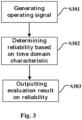
- Fig. 3 is a flowchart of a method for detecting an elevator safety chain according to some embodiments of the present application. Exemplary, the method shown in Fig. 3 is used for the detection of the elevator safety chain shown in Fig. 1 . However, it will be recognized from the following description that the method can also be applied to other types of elevator safety chains (such as safety chains with DC operating current).
- the method shown in Fig. 3 includes the following steps:
- Step S303 the detection device outputs an evaluation result on the reliability of the elevator safety chain.
- the detection device can send the evaluation result to the cloud or terminal device (such as mobile phone).
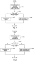
- Fig. 4 is a flowchart of a method for evaluating reliability of an elevator safety chain based on differences of time domain characteristic according to other embodiments of the present application. Exemplary, the method shown in Fig. 4 is used to implement step S302 in Fig. 3 .
- the method shown in Fig. 4 includes the following steps:
- Fig. 5 is a flowchart of a method for evaluating reliability of an elevator safety chain based on differences of time domain characteristic according to other embodiments of the present application. Exemplary, the method shown in Fig. 5 is also used to implement step S302 in Fig. 3 .
- the method shown in Fig. 5 includes the following steps:
- Fig. 6 is a flowchart of a method for evaluating reliability of an elevator safety chain based on differences of time domain characteristic according to other embodiments of the present application. Exemplary, the method shown in Fig.6 is also used to implement step S302 in Fig. 3 .
- the method shown in Fig. 6 includes the following steps:
- Fig. 7 is a flowchart of a method for evaluating reliability of an elevator safety chain based on differences of time domain characteristic according to other embodiments of the present application. Different from the embodiments shown in Figs. 4-6 , Fig. 7 judges the reliability of the elevator safety chain based on criteria associated with multiple time domain characteristic differences.
- the method shown in Fig. 7 includes the following steps:
- time domain characteristic differences described in Fig. 7 is only exemplary rather than exhaustive.
- the number and type of time domain characteristic differences in the combination may be changed, and logical relationship among the criteria may also be different (in the embodiment shown in Fig. 7 , the relationship among criteria 1-3 is a logical "or”, but it can also be changed to other logical relationships, such as the relationship "and", that is, the judgment of the possibility of failure of the landing door switch may be made only when the three criteria are met at the same time).
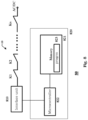
- Fig. 8 is a schematic block diagram of a device for detecting an elevator safety chain according to one or more embodiments of the present application.
- the device may be used, for example, to implement the device 20 in Fig. 1 .
- a device 80 includes an interface unit 810 and a processing unit 820, wherein the processing unit 820 includes a memory 821 (for example, nonvolatile memory such as flash memory, ROM, hard disk drive, magnetic disk, optical disc), a microcontroller 822, and a computer program 823 stored on the memory 821 and operable on the microcontroller 822.
- a memory 821 for example, nonvolatile memory such as flash memory, ROM, hard disk drive, magnetic disk, optical disc
- a microcontroller 822 for example, nonvolatile memory such as flash memory, ROM, hard disk drive, magnetic disk, optical disc
- a computer program 823 stored on the memory 821 and operable on the microcontroller 822.
- the interface unit 810 in Fig. 8 is coupled with the elevator safety chain (for example, the elevator safety chain 10 in Fig. 1 ), which is configured to output an operating signal having a first level (for example, high level) to the microcontroller 822 when the elevator safety chain is in an ON state, and an operating signal having a second level (for example, low level) to the microcontroller 822 when the elevator safety chain is in an OFF state.
- the elevator safety chain for example, the elevator safety chain 10 in Fig. 1
- an operating signal having a first level for example, high level
- a second level for example, low level
- the interface unit 810 includes an AC-DC conversion circuit (for example, a rectifier bridge), a light emitting diode, and a photoelectric coupling transistor.
- the rectifier circuit converts the incoming AC current into DC current, so that the light emitting diode enters light-emitting state, and then generates an amplified signal in the loop where the photoelectric coupling transistor is located, therefore, the operating signal applied at the I/O port of the microcontroller 822 is in the high-level state; on the other hand, when the elevator safety chain is in the open circuit state, the light emitting diode is in the OPEN state, and no signal will be generated in the loop where the photoelectric coupling transistor is located, therefore, the operating signal applied at the I/O port of the microcontroller 822 is in the low-level state.
- the memory 821 stores a computer program 823 executable by the microcontroller 822.
- the microcontroller 822 is configured to execute the computer program 823 to implement the methods shown in Figs. 3-7 .
- the operating signals applied at the I/O port of the microcontroller 822 when the elevator safety chain is in the on and OFF state, the operating signals applied at the I/O port of the microcontroller 822 have high level and low level respectively, this arrangement is not necessary.
- the operating signals applied at the I/O port of the microcontroller 822 may also have low level and high level when the elevator safety chain is in the on and OFF states, respectively.
- the device shown in Fig. 8 may also be applied to the elevator safety chain operating under the DC current by making adaptive changes to the interface unit 810 (for example, replacing the AC-DC conversion circuit with a DC-DC conversion circuit to convert the DC current flowing through the elevator safety chain into an operating signal matching the electrical feature of the I/O port of the microcontroller 822).
- a computer-readable storage medium on which a computer program is stored.
- the program is executed by the processor, the method described above with the help of Figs. 3-7 may be realized.
- the computer-readable storage medium referred to in the application includes various types of computer storage media, and may be any available medium that may be accessed by a general-purpose or special-purpose computer.
- the computer-readable storage medium may include RAM, ROM, EPROM, E2PROM, registers, hard disks, removable disks, CD-ROM or other optical disk storage, magnetic disk storage or other magnetic storage devices, or any other transitory or non-transitory medium that may be used to carry or store a desired program code unit in the form of instructions or data structures and that may be accessed by a general-purpose or special-purpose computer or a general-purpose or special-purpose processor.
- Disks as used herein usually copy data magnetically, while discs use lasers to optically copy data.
- An exemplary storage medium is coupled to the processor such that the processor can read and write information from and to the storage medium.
- the storage medium may be integrated into the processor.
- the processor and the storage medium may reside in the ASIC.
- the ASIC may reside in the user terminal.
- the processor and the storage medium may reside as discrete components in the user terminal.
Landscapes
- Maintenance And Inspection Apparatuses For Elevators (AREA)
- Elevator Door Apparatuses (AREA)
Abstract
Description
- The present application relates to elevator technology, in particular to a method and device for detecting an elevator safety chain and a computer-readable storage medium for implementing the method.
- An elevator system usually includes multiple door interlocks, each installed on the corresponding landing door and including a landing door switch for detecting the locking state and unlocking state of the door interlock. These landing door switches are connected in series with each other, and an operating signal indicating the closed state of all door switches during elevator operation is sent to an elevator control device to correctly operate an elevator car.
- In the daily maintenance of the elevator safety chain, maintenance personnel need to check all landing door switches one by one. The above method requires a lot of manpower and material resources, especially when the elevator system is installed in high-rise buildings.
- According to one aspect of the present application, there is provided a device for detecting an elevator safety chain, comprising:
- an interface unit coupled with the elevator safety chain and configured to output an operating signal having a first level when the elevator safety chain is in an ON state and an operating signal having a second level when the elevator safety chain is in an OFF state; and
- a processing unit, including:
- memory;
- a microcontroller coupled with the interface unit; and
- a computer program stored on the memory and running on the microcontroller, the running of the computer program causes: evaluating reliability of the elevator safety chain based on time domain characteristic of the operating signal output by the interface unit.
- In some examples, the time domain characteristic includes the characteristic that an amplitude of the operating signal changes with time.
- In some examples, the running of the computer program causes the reliability of the elevator safety chain to be evaluated in the following manner:
- determining a number of times the amplitude of the operating signal output by the interface unit changes within a time window, wherein the time window starts at the time when the amplitude of the operating signal jumps from the first level to the second level or from the second level to the first level;
- if the number of changes within the time window is greater than a predetermined first threshold, it is determined that at least one landing door switch in the elevator safety chain has possibility of failure.
- In some examples, width of the time window is determined based on operation parameters of a landing door.
- In some examples, the width is determined to be substantially equal to a predetermined duration that the landing door remains open when no passengers are entering an elevator car or a predicted duration that the landing door remains open when a passenger is entering the elevator car.
- In some examples, the running of the computer program causes the reliability of the elevator safety chain to be evaluated in the following manner:
- determining a duration for which the amplitude of the operating signal output by the interface unit is maintained at the first level or the second level;
- if the duration is less than a predetermined second threshold, it is determined that at least one landing door switch in the elevator safety chain has possibility of failure.
- In some examples, the second threshold is determined to be substantially equal to a predetermined duration that the landing door remains open when no passengers are entering an elevator car or a predicted duration that the landing door remains open when a passenger is entering the elevator car.
- In some examples, the running of the computer program causes the reliability of the elevator safety chain to be evaluated in the following manner:
- determining a rate of change of the amplitude of the operating signal output by the interface unit jumping from the first level to the second level or jumping from the second level to the first level;
- if the rate of change deviates from a predetermined range, it is determined that at least one landing door switch in the elevator safety chain has a possibility of failure.
- In some examples, the interface unit includes an AC-DC conversion circuit configured to convert an AC signal transmitted on the elevator safety chain into the operating signal having the first level.
- In some examples, the interface unit includes a DC-DC conversion circuit configured to convert a DC signal transmitted on the elevator safety chain into the operating signal having the first level.
- In some examples, the device is an elevator controller.
- In some examples, the running of the computer program causes an evaluation result on the reliability of the elevator safety chain to be output.
- According to another aspect of the present application, there is provided a method for detecting an elevator safety chain, which is characterized in that it comprises the following steps:
- A. generating a corresponding operating signal based on a state of the elevator safety chain, wherein the operating signal has a first level when the elevator safety chain is in an ON state, and the operating signal has a second level when the elevator safety chain is in an OFF state; and
- B. evaluating reliability of the elevator safety chain based on time domain characteristic of the generated operating signal.
- According to another aspect of the present application, there is provided a computer-readable storage medium having instructions stored in the computer-readable storage medium, when the instructions are executed by a microcontroller, the microcontroller is caused to execute the above method.
- Features of any example described herein may, wherever appropriate, be applied to any other example described herein. Where reference is made to different examples or sets of examples, it should be understood that these are not necessarily distinct but may overlap.
- The above and/or other aspects and advantages of the present application will be more clearly and easily understood from the following description of various aspects in conjunction with the accompanying drawings, in which the same or similar elements are designated by the same reference numerals. The accompanying drawings include:
-
Fig. 1 is a schematic diagram of a typical elevator safety chain. -
Figs. 2A-2D show various waveforms of operating signals reflecting states of the elevator safety chain. -
Fig. 3 is a flowchart of a method for detecting an elevator safety chain according to some embodiments of the present application. -
Fig. 4 is a flowchart of a method for evaluating reliability of an elevator safety chain based on differences of time domain characteristic according to other embodiments of the present application. -
Fig. 5 is a flowchart of a method for evaluating reliability of an elevator safety chain based on differences of time domain characteristic according to other embodiments of the present application. -
Fig. 6 is a flowchart of a method for evaluating reliability of an elevator safety chain based on differences of time domain characteristic according to other embodiments of the present application. -
Fig. 7 is a flowchart of a method for evaluating reliability of an elevator safety chain based on differences of time domain characteristic according to other embodiments of the present application. -
Fig. 8 is a schematic block diagram of a device for detecting an elevator safety chain according to one or more embodiments of the present application. - The present application is described more fully below with reference to the accompanying drawings, in which illustrative embodiments of the application are illustrated. However, the present application may be implemented in different forms and should not be construed as limited to the embodiments presented herein. The presented embodiments are intended to make the disclosure herein comprehensive and complete, so as to more comprehensively convey the protection scope of the application to those skilled in the art.
- In this specification, terms such as "comprising" and "including" mean that in addition to units and steps that are directly and clearly stated in the specification and claims, the technical solution of this application does not exclude the presence of other units and steps that are not directly and clearly stated in the specification and claims.
- Unless otherwise specified, terms such as "first" and "second" do not indicate the order of the units in terms of time, space, size, etc., but are merely used to distinguish the units.
-
Fig. 1 is a schematic diagram of a typical elevator safety chain. Anelevator safety chain 10 shown inFig. 1 includes landing door switches k1-kn connected in series with each other, each installed on their respective landing doors. Referring toFig. 1 , theelevator safety chain 10 and adetection device 20 for detecting the elevator safety chain (such as elevator controller or elevator control cabinet) are connected in series between a power supply (such as 110V AC) and a ground. Under normal circumstances, when the landing doors are all closed, the landing door switches k1-kn in theelevator safety chain 10 are all closed. At this time, an operating signal having a first level (such as a high-level signal) will be generated at thedetection device 20; on the other hand, when one of the landing doors is opened, the corresponding landing door switch in theelevator safety chain 10 will be in an opened state, and an operating signal having a second level (such as a low-level signal) will be generated at thedetection device 20 at this time. - Causes such as dust adhering to contacts, corrosion of the contacts and material aging can cause abnormal operation or misoperation of the landing door switch. For example, when the landing door is closed, the landing door switch that should be in the closed state enters the opened state, or when the landing door is opened, the landing door switch that should be in the opened state enters the closed state.
- After research, the inventors of the application found that deterioration of the landing door switch performance is a gradual process over time, that is, in the early stage, the landing door switch only occasionally misoperates, and it will eventually evolve into permanent failure over time.
- The inventors of the present application also found that, in terms of time domain characteristic, there is a significant difference between the operating signal generated on the detection device side due to the deterioration of the performance of the landing door switch and the operating signal generated on the detection device side by the landing door switch in response to an elevator control command (or the opening and closing of the landing door). Due to the existence of this difference, the hidden danger of the failure of the landing door switch may be found in time through the detection and analysis of the operating signal, which is particularly conducive to reducing the workload of elevator maintenance.
- The difference of the above time domain characteristic is further described below with the help of the accompanying drawings.
-
Figs. 2A-2D show various waveforms of operating signals reflecting states of the elevator safety chain.Fig. 2A is the waveform of the signal generated by the landing door switch on the detection device side in response to the opening and closing of the landing door, andFigs. 2B-2C are the waveforms of the operating signals caused by the deterioration of the performance of the landing door switch. In the above drawings, the vertical axis represents the amplitude or voltage of the operating signal and the horizontal axis represents the time. For example, but not necessarily, it is assumed that the high-level state of the operating signal corresponds to the state that all landing doors are closed (at this time, all landing door switches in the safety chain are closed), and the low-level state of the operating signal corresponds to the state that a landing door is opened (at this time, the landing door switch associated with the opened landing door in the safety chain is in the opened state). - As shown in
Fig. 2A , when each landing door switch in the elevator safety chain has good performance, in response to the operation that the landing door is closed, the elevator safety chain enters the ON state at time t1, and at this time, the operating signal jumps from low level L to high level H; on the other hand, in response to the operation that the landing door is opened, the elevator safety chain enters the opened state at time t2, and at this time, the operating signal jumps from high level H to low level L. - If there is a landing door switch with poor performance in the elevator safety chain, the operating signal will show time domain characteristic different from that shown in
Fig. 2A . For example, as shown inFig. 2B , the operating signal will have one or more amplitude changes within a shorter time window after the transition from low level L to high level H or from high level H to low level L (InFig. 2A , the time window with t1 as the starting point and width w and the time window with t2 as the starting point and width w). It should be noted that the amplitude of this amplitude change may be equal to the difference between high level H and low level L, but it may also be less than this difference. - In some embodiments of the present application, the signal change caused by the opening and closing of the landing door is distinguished from the signal change caused by the deterioration of the performance of the landing door switch by predetermined the width w of the time window. Optionally, the width of the time window may be determined based on operation parameters of the landing door.
- Normally, when an elevator car door is opened, if no passengers enter the car, the elevator car door and landing door will be closed automatically after a predetermined duration (e.g. 5 seconds). In some embodiments of the present application, optionally, the time t1 at which the operating signal jumps from high level H to low level L or from low level L to high level H may be determined as the starting point of the time window, and the width w of the time window may be determined to be substantially equal to a predetermined duration that the landing door remains open when no passengers are entering an elevator car.
- Optionally, the width w of the time window may be determined to be substantially equal to a predicted duration that the landing door remains open when a passenger is entering the elevator car. The predicted duration may be determined, for example, based on the operation data of the elevator. For example, the maximum duration recorded in the operation data that the landing door remains open may be determined as the predicted duration, or the duration of the landing door that appears more frequently in the operation data remains open may be determined as the predicted duration.
- It should be noted that the setting method of the time window width given above is only exemplary rather than exhaustive. Through the above description, it will be recognized that the operation parameters of the landing door that may be used to reflect the above signal change differences may be used as the basis for setting the time window width.
- When the performance of the landing door switch deteriorates, the operating signal may also show the change feature shown in
Fig. 2C . Specifically, the amplitude of the operating signal also changes outside the time window shown inFig. 2C . Compared with the case in which the signal changes in response to the opening and closing of the landing door shown inFig. 2A , at this time, due to a short change in the amplitude between t1 and t2, the duration Δt1 and Δt2 for which the operating signal maintains at high level H or low level L becomes shorter. - In addition, the deterioration of the performance of the landing door switch may also make the operating signal show the change feature as shown in
Fig. 2D . Specifically, at this time, a rate of change of the operating signal decreasing from high level to low level or increasing from low level to high level (for example, the rising edge slope of the signal near t1 and the falling edge slope near t2) is significantly deviated from the situation in response to the opening and closing of the landing door shown inFig. 2A (i.e., the falling edge slope and the rising edge slope are too fast or too slow). - It should be noted that the differences in time domain characteristic described above are only exemplary rather than exhaustive. Through the above description, it will be recognized that due to the diversity of applications and the working principle of landing door switch, the differences of time domain characteristic will also be reflected in many aspects. These differences may be used to find the potential failure of landing door switch in time.
- It should also be noted that various differences in the time domain characteristic described above and not described may be used to judge the failure of landing door switch alone, or may be constructed into various combinations for judging the failure of landing door switch.
-
Fig. 3 is a flowchart of a method for detecting an elevator safety chain according to some embodiments of the present application. Exemplary, the method shown inFig. 3 is used for the detection of the elevator safety chain shown inFig. 1 . However, it will be recognized from the following description that the method can also be applied to other types of elevator safety chains (such as safety chains with DC operating current). - The method shown in
Fig. 3 includes the following steps: - Step S301: on the side of the detection device (such as the
detection device 20 inFig. 1 ), a corresponding operating signal is generated based on the state of the elevator safety chain. Exemplary, it is assumed here that the operating signal has a high level when the elevator safety chain is in an ON state and a low level when the elevator safety chain is in an OFF state. - Step S302: the detection device evaluates the reliability of the elevator safety chain based on the time domain characteristic of the generated operating signal.
- As described above, in terms of time domain characteristic, there are significant differences in the operating signals in the case of the deterioration of the performance of the landing door switch and in response to the opening and closing of landing door. These differences may be used alone or in combination to evaluate the reliability of elevator safety chain. The specific methods of evaluation will be further described later.
- Step S303: the detection device outputs an evaluation result on the reliability of the elevator safety chain. In this step, optionally, the detection device can send the evaluation result to the cloud or terminal device (such as mobile phone).
-
Fig. 4 is a flowchart of a method for evaluating reliability of an elevator safety chain based on differences of time domain characteristic according to other embodiments of the present application. Exemplary, the method shown inFig. 4 is used to implement step S302 inFig. 3 . - The method shown in
Fig. 4 includes the following steps: - Step S401: the detection device determines the number of times the amplitude of the generated operating signal changes within the time window. Taking the case shown in
Fig. 2B as an example, the time t1 when the operating signal jumps from low level L to high level H may be set as the starting point of the time window, and the width w of the time window may be determined based on the operation parameters of the landing door. Optionally, the width w may be determined to be substantially equal to a predetermined duration that the landing door remains open when no passengers are entering an elevator car, or substantially equal to a predicted duration that the landing door remains open when a passenger is entering the elevator car. - Step S402: the detection device determines whether the number of times the amplitude of the operating signal changes within the time window is greater than a predetermined first threshold Th1. If it is greater than the predetermined first threshold Th1, go to step S403, otherwise go to step S404. The first threshold Th1 may be flexibly set according to demands of the application. For example, under the demand of high reliability, the threshold may be set smaller (for example, one), otherwise, it may be set larger.
- Step S403: the detection device will generate an evaluation result of the possibility of failure of at least one landing door switch in the elevator safety chain. After step S403, the method flow shown in
Fig. 4 will go to step S303 inFig. 3 . - Step S404: the detection device will generate an evaluation result of the high possibility of good performance of the landing door switch in the elevator safety chain. After step S403, the method flow shown in
Fig. 4 will also go to step S303 inFig. 3 . -
Fig. 5 is a flowchart of a method for evaluating reliability of an elevator safety chain based on differences of time domain characteristic according to other embodiments of the present application. Exemplary, the method shown inFig. 5 is also used to implement step S302 inFig. 3 . - The method shown in
Fig. 5 includes the following steps: - Step S501: the detection device determines the duration for which the amplitude of the operating signal is maintained at high level H or low level L. Taking the case shown in
Fig. 2C as an example, the duration of the operating signal maintaining the high level H from time t1 is Δt1, and the duration of the operating signal maintaining the low level L from time t2 is Δt2. The above duration may be used for the determination of step S502. - Step S502: the detection device determines whether the duration is less than a predetermined second threshold Th2. If less than the predetermined second threshold Th2, go to step S503, otherwise go to step S504. The second threshold Th2 can also be flexibly set according to demands of the application. For example, under the demand of high reliability, the threshold may be set larger, for example, it is substantially equal to a predetermined duration that the landing door remains open when no passengers are entering an elevator car, or substantially equal to a predicted duration that the landing door remains open when a passenger is entering the elevator car. Otherwise, it may be predetermined smaller.
- Step S503: the detection device will generate an evaluation result of the possibility of failure of at least one landing door switch in the elevator safety chain. After step S503, the method flow shown in
Fig. 5 will go to step S303 inFig. 3 . - Step S504: the detection device will generate an evaluation result of the high possibility of good performance of the landing door switch in the elevator safety chain. After step S503, the method flow shown in
Fig. 5 will also go to step S303 inFig. 3 . -
Fig. 6 is a flowchart of a method for evaluating reliability of an elevator safety chain based on differences of time domain characteristic according to other embodiments of the present application. Exemplary, the method shown inFig.6 is also used to implement step S302 inFig. 3 . - The method shown in
Fig. 6 includes the following steps: - Step S601: the detection device determines a rate of change of the amplitude of the operating signal from high level H to low level L or from low level L to high level H. Taking the case shown in
Fig. 2D as an example, the slope of the rising edge of the operating signal near time t1 or the slope of the falling edge near time t2 may be taken as the rate of change. - Step S602: the detection device determines whether the rate of change of the operating signal determined in step S601 significantly deviates from the rate of change of the operating signal generated in response to the opening and closing of the landing door. If it deviates, proceed to step S603, otherwise proceed to step S604. Optionally, the degree of deviation may be measured within a predetermined range. In one example, the range may be bounded at both ends, that is, the upper and lower limits of the range are finite values. In another example, the predetermined range is bounded at one end. For example, the lower limit of the range is limited (because generally, the rate of change of the operating signal will be reduced after the deterioration of the performance of the landing door switch). Similarly, the range for measuring the degree of deviation may be flexibly set according to demands of the application. For example, under the demand of high reliability, the range may be predetermined smaller, otherwise, it may be predetermined larger.
- Step S603: the detection device will generate an evaluation result of the possibility of failure of at least one landing door switch in the elevator safety chain. After step S603, the method flow shown in
Fig. 6 will go to step S303 inFig. 3 . - Step S604: the detection device will generate an evaluation result of the high possibility of good performance of the landing door switch in the elevator safety chain. After step S603, the method flow shown in
Fig. 6 will also go to step S303 inFig. 3 . - As described above, various differences in time domain characteristic may be used to judge the reliability of elevator safety chain alone, or may be constructed into various combinations for judging the reliability of elevator safety chain.
Fig. 7 is a flowchart of a method for evaluating reliability of an elevator safety chain based on differences of time domain characteristic according to other embodiments of the present application. Different from the embodiments shown inFigs. 4-6 ,Fig. 7 judges the reliability of the elevator safety chain based on criteria associated with multiple time domain characteristic differences. - The method shown in
Fig. 7 includes the following steps: - S701: the detection device determines the number of times the amplitude of the generated operating signal changes within the time window.
- Step S702: the detection device determines whether the number of times the amplitude of the operating signal changes within the time window is greater than a predetermined first threshold Th1 (hereinafter referred to as criterion 1). If it is greater than, go to step S703, otherwise go to step S704.
- Step S703: the detection device will generate an evaluation result of the possibility of failure of at least one landing door switch in the elevator safety chain. After step S703, the method flow shown in
Fig. 7 will go to step S303 inFig. 3 . - Step S704: the detection device determines the duration for which the amplitude of the operating signal is maintained at high level H or low level L.
- Step S705: the detection device determines whether the duration is less than a predetermined second threshold Th2 (hereinafter referred to as criterion 2). If it is less than, go to step S703, otherwise go to step S706.
- Step s706: the detection device determines a rate of change of the amplitude of the operating signal from high level H to low level L or from low level L to high level H.
- Step S707: the detection device determines whether the rate of change of the operating signal determined in step S706 significantly deviates from the rate of change of the operating signal generated in response to the opening and closing of the landing door (hereinafter referred to as criterion 3). If it deviates, proceed to step S703, otherwise proceed to step S708.
- Step S708: the detection device will generate an evaluation result of the high possibility of good performance of the landing door switch in the elevator safety chain. After step S708, the method flow shown in
Fig. 7 will also go to step S303 inFig. 3 . - It should be noted that the combination of time domain characteristic differences described in
Fig. 7 is only exemplary rather than exhaustive. For example, the number and type of time domain characteristic differences in the combination may be changed, and logical relationship among the criteria may also be different (in the embodiment shown inFig. 7 , the relationship among criteria 1-3 is a logical "or", but it can also be changed to other logical relationships, such as the relationship "and", that is, the judgment of the possibility of failure of the landing door switch may be made only when the three criteria are met at the same time). -
Fig. 8 is a schematic block diagram of a device for detecting an elevator safety chain according to one or more embodiments of the present application. The device may be used, for example, to implement thedevice 20 inFig. 1 . - As shown in
Fig. 8 , adevice 80 includes aninterface unit 810 and aprocessing unit 820, wherein theprocessing unit 820 includes a memory 821 (for example, nonvolatile memory such as flash memory, ROM, hard disk drive, magnetic disk, optical disc), amicrocontroller 822, and acomputer program 823 stored on thememory 821 and operable on themicrocontroller 822. - The
interface unit 810 inFig. 8 is coupled with the elevator safety chain (for example, theelevator safety chain 10 inFig. 1 ), which is configured to output an operating signal having a first level (for example, high level) to themicrocontroller 822 when the elevator safety chain is in an ON state, and an operating signal having a second level (for example, low level) to themicrocontroller 822 when the elevator safety chain is in an OFF state. - Exemplary, the
interface unit 810 includes an AC-DC conversion circuit (for example, a rectifier bridge), a light emitting diode, and a photoelectric coupling transistor. When the elevator safety chain is in the ON state, the rectifier circuit converts the incoming AC current into DC current, so that the light emitting diode enters light-emitting state, and then generates an amplified signal in the loop where the photoelectric coupling transistor is located, therefore, the operating signal applied at the I/O port of themicrocontroller 822 is in the high-level state; on the other hand, when the elevator safety chain is in the open circuit state, the light emitting diode is in the OPEN state, and no signal will be generated in the loop where the photoelectric coupling transistor is located, therefore, the operating signal applied at the I/O port of themicrocontroller 822 is in the low-level state. - In the device shown in
Fig. 8 , thememory 821 stores acomputer program 823 executable by themicrocontroller 822. Themicrocontroller 822 is configured to execute thecomputer program 823 to implement the methods shown inFigs. 3-7 . - It should be noted that although in the example given here, when the elevator safety chain is in the on and OFF state, the operating signals applied at the I/O port of the
microcontroller 822 have high level and low level respectively, this arrangement is not necessary. In another example, the operating signals applied at the I/O port of themicrocontroller 822 may also have low level and high level when the elevator safety chain is in the on and OFF states, respectively. In addition, the device shown inFig. 8 may also be applied to the elevator safety chain operating under the DC current by making adaptive changes to the interface unit 810 (for example, replacing the AC-DC conversion circuit with a DC-DC conversion circuit to convert the DC current flowing through the elevator safety chain into an operating signal matching the electrical feature of the I/O port of the microcontroller 822). - According to another aspect of the present application, there is also provided a computer-readable storage medium on which a computer program is stored. When the program is executed by the processor, the method described above with the help of
Figs. 3-7 may be realized. - The computer-readable storage medium referred to in the application includes various types of computer storage media, and may be any available medium that may be accessed by a general-purpose or special-purpose computer. For example, the computer-readable storage medium may include RAM, ROM, EPROM, E2PROM, registers, hard disks, removable disks, CD-ROM or other optical disk storage, magnetic disk storage or other magnetic storage devices, or any other transitory or non-transitory medium that may be used to carry or store a desired program code unit in the form of instructions or data structures and that may be accessed by a general-purpose or special-purpose computer or a general-purpose or special-purpose processor. Disks as used herein usually copy data magnetically, while discs use lasers to optically copy data. The above combination should also be included in the protection scope of the computer-readable storage medium. An exemplary storage medium is coupled to the processor such that the processor can read and write information from and to the storage medium. In the alternative, the storage medium may be integrated into the processor. The processor and the storage medium may reside in the ASIC. The ASIC may reside in the user terminal. In the alternative, the processor and the storage medium may reside as discrete components in the user terminal.
- Those skilled in the art will appreciate that the various illustrative logical blocks, modules, circuits, and algorithm steps described herein may be implemented as electronic hardware, computer software, or combinations of both.
- To demonstrate this interchangeability of hardware and software, various illustrative components, blocks, modules, circuits, and steps have been described above generally in terms of their functionality. Whether such functionality is implemented in hardware or software depends on the particular application and design constraints imposed on the overall system. Those skilled in the art may implement the described functionality in varying ways for the particular application. However, such implementation decisions should not be interpreted as causing a departure from the scope of the present application.
- Although only a few of the specific embodiments of the present application have been described, those skilled in the art will recognize that the present application may be embodied in many other forms without departing from the scope thereof. Accordingly, the examples and embodiments shown are to be regarded as illustrative and not restrictive, and various modifications and substitutions may be covered by the application without departing from the scope of the application as defined by the appended claims.
- The embodiments and examples presented herein are provided to best illustrate embodiments in accordance with the present technology and its particular application, and to thereby enable those skilled in the art to implement and use the present application. However, those skilled in the art will appreciate that the above description and examples are provided for convenience of illustration and example only. The presented description is not intended to cover every aspect of the application or to limit the application to the precise form disclosed.
Claims (15)
- A device for detecting an elevator safety chain, which is characterized in that it comprises:an interface unit coupled with the elevator safety chain and configured to output an operating signal having a first level when the elevator safety chain is in an ON state and an operating signal having a second level when the elevator safety chain is in an OFF state; anda processing unit, including:memory;a microcontroller coupled with the interface unit; anda computer program stored on the memory and running on the microcontroller, the running of the computer program causes the reliability of the elevator safety chain to be evaluated based on a time domain characteristic of the operating signal output by the interface unit.
- The device according to claim 1, wherein the time domain characteristic includes a characteristic of how an amplitude of the operating signal changes with time.
- The device according to claim 1 or 2, wherein the running of the computer program causes the reliability of the elevator safety chain to be evaluated in the following manner:determining a number of times the amplitude of the operating signal output by the interface unit changes within a time window, wherein the time window starts at the time when the amplitude of the operating signal jumps from the first level to the second level or from the second level to the first level;if the number of changes within the time window is greater than a predetermined first threshold, it is determined that at least one landing door switch in the elevator safety chain has possibility of failure;wherein, optionally, a width of the time window is determined based on operation parameters of a landing door; andfurther optionally, wherein the width is determined to be substantially equal to a predetermined duration that the landing door remains open when no passengers are entering an elevator car or a predicted duration that the landing door remains open when a passenger is entering the elevator car.
- The device according to any preceding claim, wherein the running of the computer program causes the reliability of the elevator safety chain to be evaluated in the following manner:determining a duration for which the amplitude of the operating signal output by the interface unit is maintained at the first level or the second level;if the duration is less than a predetermined second threshold, it is determined that at least one landing door switch in the elevator safety chain has possibility of failure;wherein, optionally, the second threshold is determined to be substantially equal to a predetermined duration that the landing door remains open when no passengers are entering an elevator car or a predicted duration that the landing door remains open when a passenger is entering the elevator car.
- The device according to any preceding claim, wherein the running of the computer program causes the reliability of the elevator safety chain to be evaluated in the following manner:determining a rate of change of the amplitude of the operating signal output by the interface unit jumping from the first level to the second level or jumping from the second level to the first level;if the rate of change deviates from a predetermined range, it is determined that at least one landing door switch in the elevator safety chain has a possibility of failure.
- The device according to any preceding claim, wherein:the interface unit includes an AC-DC conversion circuit configured to convert an AC signal transmitted on the elevator safety chain into the operating signal having the first level; and/orthe interface unit includes a DC-DC conversion circuit configured to convert a DC signal transmitted on the elevator safety chain into the operating signal having the first level.
- The device according to any preceding claim, wherein the device is an elevator controller.
- The device according to any preceding claim, wherein the running of the computer program causes an evaluation result on the reliability of the elevator safety chain to be output.
- A method for detecting an elevator safety chain, which is characterized in that it comprises the following steps:A. generating a corresponding operating signal based on a state of the elevator safety chain, wherein the operating signal has a first level when the elevator safety chain is in an ON state, and the operating signal has a second level when the elevator safety chain is in an OFF state; andB. evaluating reliability of the elevator safety chain based on time domain characteristic of the generated operating signal.
- The method according to claim 9, wherein the time domain characteristic includes the characteristic that an amplitude of the operating signal changes with time.
- The method according to claim 9 or 10, wherein step B comprises:B1. determining a number of times the amplitude of the operating signal changes within a time window, wherein the time window starts at the time when the amplitude of the operating signal jumps from the first level to the second level or from the second level to the first level;B2. if the number of changes within the time window is greater than a predetermined first threshold, it is determined that at least one landing door switch in the elevator safety chain has possibility of failure;wherein, optionally, a width of the time window is determined based on operation parameters of a landing door; andfurther optionally, wherein the width is determined to be substantially equal to a predetermined duration that the landing door remains open when no passengers are entering an elevator car or a predicted duration that the landing door remains open when a passenger is entering the elevator car.
- The method according to any of claims 9-11, wherein step B comprises:B1'. determining a duration for which the amplitude of the operating signal is maintained at the first level or the second level;B2'. if the duration is less than a predetermined second threshold, it is determined that at least one landing door switch in the elevator safety chain has possibility of failure;wherein, optionally, the second threshold is determined to be substantially equal to a predetermined duration that the landing door remains open when no passengers are entering an elevator car or a predicted duration that the landing door remains open when a passenger is entering the elevator car.
- The method according to any of claims 9-12, wherein step B comprises:B1". determining a rate of change of the amplitude of the operating signal jumping from the first level to the second level or jumping from the second level to the first level;B2". if the rate of change deviates from a predetermined range, it is determined that at least one landing door switch in the elevator safety chain has possibility of failure.
- The method according to any of claims 9-13, further comprising:
C. outputting an evaluation result on the reliability of the elevator safety chain. - A computer-readable storage medium having instructions stored in the computer-readable storage medium, which is characterized in that, when the instructions are executed by a processor, the processor is caused to execute the method of any of claims 9-14.
Applications Claiming Priority (1)
| Application Number | Priority Date | Filing Date | Title |
|---|---|---|---|
| CN202210005863.2A CN116424979A (en) | 2022-01-04 | 2022-01-04 | Method and device for detecting elevator safety link |
Publications (2)
| Publication Number | Publication Date |
|---|---|
| EP4206106A1 true EP4206106A1 (en) | 2023-07-05 |
| EP4206106B1 EP4206106B1 (en) | 2025-05-07 |
Family
ID=84358816
Family Applications (1)
| Application Number | Title | Priority Date | Filing Date |
|---|---|---|---|
| EP22208168.9A Active EP4206106B1 (en) | 2022-01-04 | 2022-11-17 | Method and device for detecting elevator safety chain |
Country Status (3)
| Country | Link |
|---|---|
| US (1) | US20230211979A1 (en) |
| EP (1) | EP4206106B1 (en) |
| CN (1) | CN116424979A (en) |
Citations (2)
| Publication number | Priority date | Publication date | Assignee | Title |
|---|---|---|---|---|
| CN110894038A (en) * | 2019-11-20 | 2020-03-20 | 上海电气集团股份有限公司 | Method and device for predicting running state of elevator door system |
| EP3628625A1 (en) * | 2018-09-26 | 2020-04-01 | Otis Elevator Company | Time domain reflectometry for electrical safety chain condition based maintenance |
-
2022
- 2022-01-04 CN CN202210005863.2A patent/CN116424979A/en active Pending
- 2022-10-17 US US17/967,175 patent/US20230211979A1/en active Pending
- 2022-11-17 EP EP22208168.9A patent/EP4206106B1/en active Active
Patent Citations (2)
| Publication number | Priority date | Publication date | Assignee | Title |
|---|---|---|---|---|
| EP3628625A1 (en) * | 2018-09-26 | 2020-04-01 | Otis Elevator Company | Time domain reflectometry for electrical safety chain condition based maintenance |
| CN110894038A (en) * | 2019-11-20 | 2020-03-20 | 上海电气集团股份有限公司 | Method and device for predicting running state of elevator door system |
Also Published As
| Publication number | Publication date |
|---|---|
| US20230211979A1 (en) | 2023-07-06 |
| CN116424979A (en) | 2023-07-14 |
| EP4206106B1 (en) | 2025-05-07 |
Similar Documents
| Publication | Publication Date | Title |
|---|---|---|
| US12143065B2 (en) | Systems and methods for an enhanced watchdog in solar module installations | |
| KR102176638B1 (en) | System and Method for Fault Diagnosis and Failure Prediction of a Track Translator | |
| US9866017B2 (en) | DC power generation system and protection method for DC power generation system | |
| KR102118340B1 (en) | Transformer fault diagnosis with sound information | |
| GB2421644A (en) | Smart battery with failure verification | |
| CN110323773B (en) | Commutation failure prediction method and system considering multi-factor influence | |
| US9716461B2 (en) | Motor drive having function of detecting circuit abnormality owing to entering foreign matter before significant abnormality occurs | |
| US20150032313A1 (en) | Method and means for contactor monitoring in electric vehicle supply equipment | |
| EP4206106B1 (en) | Method and device for detecting elevator safety chain | |
| WO2022165701A1 (en) | Control method and distributed electric power system | |
| CN218974508U (en) | Star circuit detecting system is sealed to elevator | |
| CN112960524B (en) | Method, device, equipment and medium for detecting elevator door | |
| CN104600973A (en) | Control method and device for staggered PFC (positive feedback circuit) of air conditioner | |
| CN119472468B (en) | A mobile gate safety detection control system and method | |
| KR20190117906A (en) | In-vehicle controller and method for controlling the same | |
| JP6772827B2 (en) | Air conditioner | |
| CN210247109U (en) | Real-time detection LED drive circuit | |
| US9170568B1 (en) | Fail-safe static switch | |
| US11469749B2 (en) | Power controller configured to distinguish an intentional signal associated with a manual rescue mode from an unintentional signal associated with a short circuit | |
| AU2018100635A4 (en) | Feedback method for abnormal door-opening conditions of elevator and elevator | |
| CN103423964A (en) | Refrigerator and load control method thereof | |
| EP4512759B1 (en) | Device, method for monitoring state of landing and car door circuit and elevator system | |
| Bauer et al. | Optimal threshold selection and efficacy evaluation for a generic dc series arc detection algorithm | |
| CN117805574A (en) | Elevator star sealing circuit detection system and detection method thereof | |
| JP6058455B2 (en) | Cord short-circuit detection circuit and outlet device |
Legal Events
| Date | Code | Title | Description |
|---|---|---|---|
| PUAI | Public reference made under article 153(3) epc to a published international application that has entered the european phase |
Free format text: ORIGINAL CODE: 0009012 |
|
| STAA | Information on the status of an ep patent application or granted ep patent |
Free format text: STATUS: THE APPLICATION HAS BEEN PUBLISHED |
|
| AK | Designated contracting states |
Kind code of ref document: A1 Designated state(s): AL AT BE BG CH CY CZ DE DK EE ES FI FR GB GR HR HU IE IS IT LI LT LU LV MC ME MK MT NL NO PL PT RO RS SE SI SK SM TR |
|
| STAA | Information on the status of an ep patent application or granted ep patent |
Free format text: STATUS: REQUEST FOR EXAMINATION WAS MADE |
|
| 17P | Request for examination filed |
Effective date: 20240103 |
|
| RBV | Designated contracting states (corrected) |
Designated state(s): AL AT BE BG CH CY CZ DE DK EE ES FI FR GB GR HR HU IE IS IT LI LT LU LV MC ME MK MT NL NO PL PT RO RS SE SI SK SM TR |
|
| GRAP | Despatch of communication of intention to grant a patent |
Free format text: ORIGINAL CODE: EPIDOSNIGR1 |
|
| STAA | Information on the status of an ep patent application or granted ep patent |
Free format text: STATUS: GRANT OF PATENT IS INTENDED |
|
| INTG | Intention to grant announced |
Effective date: 20241223 |
|
| GRAS | Grant fee paid |
Free format text: ORIGINAL CODE: EPIDOSNIGR3 |
|
| GRAA | (expected) grant |
Free format text: ORIGINAL CODE: 0009210 |
|
| STAA | Information on the status of an ep patent application or granted ep patent |
Free format text: STATUS: THE PATENT HAS BEEN GRANTED |
|
| AK | Designated contracting states |
Kind code of ref document: B1 Designated state(s): AL AT BE BG CH CY CZ DE DK EE ES FI FR GB GR HR HU IE IS IT LI LT LU LV MC ME MK MT NL NO PL PT RO RS SE SI SK SM TR |
|
| REG | Reference to a national code |
Ref country code: GB Ref legal event code: FG4D |
|
| REG | Reference to a national code |
Ref country code: CH Ref legal event code: EP |
|
| REG | Reference to a national code |
Ref country code: DE Ref legal event code: R096 Ref document number: 602022014199 Country of ref document: DE |
|
| REG | Reference to a national code |
Ref country code: IE Ref legal event code: FG4D |
|
| REG | Reference to a national code |
Ref country code: NL Ref legal event code: MP Effective date: 20250507 |
|
| PG25 | Lapsed in a contracting state [announced via postgrant information from national office to epo] |
Ref country code: PT Free format text: LAPSE BECAUSE OF FAILURE TO SUBMIT A TRANSLATION OF THE DESCRIPTION OR TO PAY THE FEE WITHIN THE PRESCRIBED TIME-LIMIT Effective date: 20250908 Ref country code: ES Free format text: LAPSE BECAUSE OF FAILURE TO SUBMIT A TRANSLATION OF THE DESCRIPTION OR TO PAY THE FEE WITHIN THE PRESCRIBED TIME-LIMIT Effective date: 20250507 Ref country code: FI Free format text: LAPSE BECAUSE OF FAILURE TO SUBMIT A TRANSLATION OF THE DESCRIPTION OR TO PAY THE FEE WITHIN THE PRESCRIBED TIME-LIMIT Effective date: 20250507 |
|
| REG | Reference to a national code |
Ref country code: LT Ref legal event code: MG9D |
|
| PG25 | Lapsed in a contracting state [announced via postgrant information from national office to epo] |
Ref country code: GR Free format text: LAPSE BECAUSE OF FAILURE TO SUBMIT A TRANSLATION OF THE DESCRIPTION OR TO PAY THE FEE WITHIN THE PRESCRIBED TIME-LIMIT Effective date: 20250808 Ref country code: NO Free format text: LAPSE BECAUSE OF FAILURE TO SUBMIT A TRANSLATION OF THE DESCRIPTION OR TO PAY THE FEE WITHIN THE PRESCRIBED TIME-LIMIT Effective date: 20250807 |
|
| PG25 | Lapsed in a contracting state [announced via postgrant information from national office to epo] |
Ref country code: NL Free format text: LAPSE BECAUSE OF FAILURE TO SUBMIT A TRANSLATION OF THE DESCRIPTION OR TO PAY THE FEE WITHIN THE PRESCRIBED TIME-LIMIT Effective date: 20250507 Ref country code: PL Free format text: LAPSE BECAUSE OF FAILURE TO SUBMIT A TRANSLATION OF THE DESCRIPTION OR TO PAY THE FEE WITHIN THE PRESCRIBED TIME-LIMIT Effective date: 20250507 |
|
| REG | Reference to a national code |
Ref country code: AT Ref legal event code: MK05 Ref document number: 1792317 Country of ref document: AT Kind code of ref document: T Effective date: 20250507 |
|
| PG25 | Lapsed in a contracting state [announced via postgrant information from national office to epo] |
Ref country code: BG Free format text: LAPSE BECAUSE OF FAILURE TO SUBMIT A TRANSLATION OF THE DESCRIPTION OR TO PAY THE FEE WITHIN THE PRESCRIBED TIME-LIMIT Effective date: 20250507 |
|
| PG25 | Lapsed in a contracting state [announced via postgrant information from national office to epo] |
Ref country code: HR Free format text: LAPSE BECAUSE OF FAILURE TO SUBMIT A TRANSLATION OF THE DESCRIPTION OR TO PAY THE FEE WITHIN THE PRESCRIBED TIME-LIMIT Effective date: 20250507 |
|
| PG25 | Lapsed in a contracting state [announced via postgrant information from national office to epo] |
Ref country code: AT Free format text: LAPSE BECAUSE OF FAILURE TO SUBMIT A TRANSLATION OF THE DESCRIPTION OR TO PAY THE FEE WITHIN THE PRESCRIBED TIME-LIMIT Effective date: 20250507 |
|
| PG25 | Lapsed in a contracting state [announced via postgrant information from national office to epo] |
Ref country code: RS Free format text: LAPSE BECAUSE OF FAILURE TO SUBMIT A TRANSLATION OF THE DESCRIPTION OR TO PAY THE FEE WITHIN THE PRESCRIBED TIME-LIMIT Effective date: 20250807 |
|
| PG25 | Lapsed in a contracting state [announced via postgrant information from national office to epo] |
Ref country code: IS Free format text: LAPSE BECAUSE OF FAILURE TO SUBMIT A TRANSLATION OF THE DESCRIPTION OR TO PAY THE FEE WITHIN THE PRESCRIBED TIME-LIMIT Effective date: 20250907 |
|
| PG25 | Lapsed in a contracting state [announced via postgrant information from national office to epo] |
Ref country code: LV Free format text: LAPSE BECAUSE OF FAILURE TO SUBMIT A TRANSLATION OF THE DESCRIPTION OR TO PAY THE FEE WITHIN THE PRESCRIBED TIME-LIMIT Effective date: 20250507 |
|
| PGFP | Annual fee paid to national office [announced via postgrant information from national office to epo] |
Ref country code: DE Payment date: 20251022 Year of fee payment: 4 |
|
| PG25 | Lapsed in a contracting state [announced via postgrant information from national office to epo] |
Ref country code: DK Free format text: LAPSE BECAUSE OF FAILURE TO SUBMIT A TRANSLATION OF THE DESCRIPTION OR TO PAY THE FEE WITHIN THE PRESCRIBED TIME-LIMIT Effective date: 20250507 Ref country code: SM Free format text: LAPSE BECAUSE OF FAILURE TO SUBMIT A TRANSLATION OF THE DESCRIPTION OR TO PAY THE FEE WITHIN THE PRESCRIBED TIME-LIMIT Effective date: 20250507 |
|
| PGFP | Annual fee paid to national office [announced via postgrant information from national office to epo] |
Ref country code: FR Payment date: 20251022 Year of fee payment: 4 |
|
| PG25 | Lapsed in a contracting state [announced via postgrant information from national office to epo] |
Ref country code: CZ Free format text: LAPSE BECAUSE OF FAILURE TO SUBMIT A TRANSLATION OF THE DESCRIPTION OR TO PAY THE FEE WITHIN THE PRESCRIBED TIME-LIMIT Effective date: 20250507 |
|
| PG25 | Lapsed in a contracting state [announced via postgrant information from national office to epo] |
Ref country code: EE Free format text: LAPSE BECAUSE OF FAILURE TO SUBMIT A TRANSLATION OF THE DESCRIPTION OR TO PAY THE FEE WITHIN THE PRESCRIBED TIME-LIMIT Effective date: 20250507 |
|
| PG25 | Lapsed in a contracting state [announced via postgrant information from national office to epo] |
Ref country code: SK Free format text: LAPSE BECAUSE OF FAILURE TO SUBMIT A TRANSLATION OF THE DESCRIPTION OR TO PAY THE FEE WITHIN THE PRESCRIBED TIME-LIMIT Effective date: 20250507 |
|
| PG25 | Lapsed in a contracting state [announced via postgrant information from national office to epo] |
Ref country code: IT Free format text: LAPSE BECAUSE OF FAILURE TO SUBMIT A TRANSLATION OF THE DESCRIPTION OR TO PAY THE FEE WITHIN THE PRESCRIBED TIME-LIMIT Effective date: 20250507 |
|
| REG | Reference to a national code |
Ref country code: DE Ref legal event code: R097 Ref document number: 602022014199 Country of ref document: DE |
|
| PG25 | Lapsed in a contracting state [announced via postgrant information from national office to epo] |
Ref country code: RO Free format text: LAPSE BECAUSE OF FAILURE TO SUBMIT A TRANSLATION OF THE DESCRIPTION OR TO PAY THE FEE WITHIN THE PRESCRIBED TIME-LIMIT Effective date: 20250507 |
|
| PLBE | No opposition filed within time limit |
Free format text: ORIGINAL CODE: 0009261 |
|
| STAA | Information on the status of an ep patent application or granted ep patent |
Free format text: STATUS: NO OPPOSITION FILED WITHIN TIME LIMIT |
|
| REG | Reference to a national code |
Ref country code: CH Ref legal event code: L10 Free format text: ST27 STATUS EVENT CODE: U-0-0-L10-L00 (AS PROVIDED BY THE NATIONAL OFFICE) Effective date: 20260318 |
|
| 26N | No opposition filed |
Effective date: 20260210 |