EP4206071A1 - Marine propulsion system - Google Patents
Marine propulsion system Download PDFInfo
- Publication number
- EP4206071A1 EP4206071A1 EP22215535.0A EP22215535A EP4206071A1 EP 4206071 A1 EP4206071 A1 EP 4206071A1 EP 22215535 A EP22215535 A EP 22215535A EP 4206071 A1 EP4206071 A1 EP 4206071A1
- Authority
- EP
- European Patent Office
- Prior art keywords
- thrust
- marine vessel
- propulsion device
- auxiliary
- marine
- Prior art date
- Legal status (The legal status is an assumption and is not a legal conclusion. Google has not performed a legal analysis and makes no representation as to the accuracy of the status listed.)
- Granted
Links
Images


Classifications
-
- B—PERFORMING OPERATIONS; TRANSPORTING
- B63—SHIPS OR OTHER WATERBORNE VESSELS; RELATED EQUIPMENT
- B63H—MARINE PROPULSION OR STEERING
- B63H20/00—Outboard propulsion units, e.g. outboard motors or Z-drives; Arrangements thereof on vessels
- B63H20/08—Means enabling movement of the position of the propulsion element, e.g. for trim, tilt or steering; Control of trim or tilt
- B63H20/12—Means enabling steering
-
- B—PERFORMING OPERATIONS; TRANSPORTING
- B63—SHIPS OR OTHER WATERBORNE VESSELS; RELATED EQUIPMENT
- B63H—MARINE PROPULSION OR STEERING
- B63H20/00—Outboard propulsion units, e.g. outboard motors or Z-drives; Arrangements thereof on vessels
- B63H20/007—Trolling propulsion units
-
- B—PERFORMING OPERATIONS; TRANSPORTING
- B63—SHIPS OR OTHER WATERBORNE VESSELS; RELATED EQUIPMENT
- B63H—MARINE PROPULSION OR STEERING
- B63H20/00—Outboard propulsion units, e.g. outboard motors or Z-drives; Arrangements thereof on vessels
- B63H20/02—Mounting of propulsion units
-
- G—PHYSICS
- G05—CONTROLLING; REGULATING
- G05D—SYSTEMS FOR CONTROLLING OR REGULATING NON-ELECTRIC VARIABLES
- G05D1/00—Control of position, course, altitude or attitude of land, water, air or space vehicles, e.g. using automatic pilots
- G05D1/02—Control of position or course in two dimensions
- G05D1/0206—Control of position or course in two dimensions specially adapted to water vehicles
-
- B—PERFORMING OPERATIONS; TRANSPORTING
- B63—SHIPS OR OTHER WATERBORNE VESSELS; RELATED EQUIPMENT
- B63H—MARINE PROPULSION OR STEERING
- B63H20/00—Outboard propulsion units, e.g. outboard motors or Z-drives; Arrangements thereof on vessels
- B63H2020/003—Arrangements of two, or more outboard propulsion units
-
- B—PERFORMING OPERATIONS; TRANSPORTING
- B63—SHIPS OR OTHER WATERBORNE VESSELS; RELATED EQUIPMENT
- B63H—MARINE PROPULSION OR STEERING
- B63H21/00—Use of propulsion power plant or units on vessels
- B63H21/20—Use of propulsion power plant or units on vessels the vessels being powered by combinations of different types of propulsion units
- B63H2021/202—Use of propulsion power plant or units on vessels the vessels being powered by combinations of different types of propulsion units of hybrid electric type
- B63H2021/205—Use of propulsion power plant or units on vessels the vessels being powered by combinations of different types of propulsion units of hybrid electric type the second power unit being of the internal combustion engine type, or the like, e.g. a Diesel engine
-
- B—PERFORMING OPERATIONS; TRANSPORTING
- B63—SHIPS OR OTHER WATERBORNE VESSELS; RELATED EQUIPMENT
- B63H—MARINE PROPULSION OR STEERING
- B63H21/00—Use of propulsion power plant or units on vessels
- B63H21/21—Control means for engine or transmission, specially adapted for use on marine vessels
- B63H2021/216—Control means for engine or transmission, specially adapted for use on marine vessels using electric control means
Definitions
- the present invention relates to a marine propulsion system, and more particularly, it relates to a marine propulsion system that is able to adjust the thrust of a marine vessel to less than a troll thrust, which is a minimum thrust generated when an engine continuously drives a thruster. It also relates to a marine vessel comprising such a marine propulsion system.
- a marine vessel that is able to adjust the thrust of the marine vessel to less than a troll thrust, which is a minimum thrust generated when an engine continuously drives a thruster is known in general.
- a troll thrust which is a minimum thrust generated when an engine continuously drives a thruster.
- JP 6 156 926 B2 discloses a marine vessel including a vessel body and an outboard motor corresponding to a propulsion unit attached to the vessel body.
- the outboard motor of the marine vessel disclosed in JP 6 156 926 B2 includes a propulsion device (thruster), an engine to generate a thrust from the propulsion device, and a shift actuator to switch the outboard motor between a shift-in state (forward or reverse movement state) and a neutral state.
- the shift-in state and the neutral state of the outboard motor are alternately repeated at predetermined time intervals such that the marine vessel is able to navigate at a speed lower than a speed at which the thrust of the marine vessel becomes a minimum thrust (troll thrust) generated when the engine continuously drives the thruster.
- the shift-in state and the neutral state of the outboard motor are alternately repeated at the predetermined time intervals, and thus very small changes in the speed of the marine vessel are repeated. That is, the speed of the marine vessel is not stable when the marine vessel navigates at the speed lower than the speed in the troll thrust state.
- the shift-in state and the neutral state of the outboard motor are alternately repeated at the predetermined time intervals, and thus noises and vibrations are repeatedly generated when the outboard motor is switched between the shift-in state and the neutral state.
- the quietness of the marine vessel is reduced when the marine vessel navigates at the speed lower than the speed in the troll thrust state. Therefore, it is desired to stabilize the speed of the marine vessel and to improve the quietness of the marine vessel when the marine vessel navigates at the speed lower than the speed in the troll thrust state.
- SDGs Stustainable Development Goals
- said object is solved by a marine propulsion system having the features of independent claim 1. Preferred embodiments are laid down in the dependent claims.
- a marine propulsion system comprises a main propulsion device configured to be attached to a stern of a hull, including an engine configured to drive a main thruster to generate a thrust, and configured to rotate in a right-left direction to change a direction of the thrust, an auxiliary propulsion device configured to be attached to the stern, including an electric motor configured to drive an auxiliary thruster to generate a thrust, configured to rotate in the right-left direction to change a direction of the thrust, and having a minimum output smaller than a minimum output of the main propulsion device, and a controller configured or programmed to perform an electric drive control to cause the electric motor to drive the auxiliary thruster in the auxiliary propulsion device without performing an engine drive control to cause the engine to drive the main thruster in the main propulsion device when adjusting a thrust of a marine vessel to less than a troll thrust corresponding to a minimum thrust generated when the engine continuously drives the main thruster.
- a marine propulsion system includes the controller configured or programmed to perform the electric drive control to cause the electric motor to drive the auxiliary thruster having a minimum output smaller than the minimum output of the main thruster in the auxiliary propulsion device without performing the engine drive control to cause the engine to drive the main thruster in the main propulsion device when adjusting the thrust of the marine vessel to less than the troll thrust. Accordingly, when the thrust of the marine vessel is adjusted to less than the troll thrust, the electric drive control is performed without performing the engine drive control such that the thrust of the marine vessel is changed to less than the troll thrust without alternately repeating the shift-in state and the neutral state of the main propulsion device at predetermined time intervals.
- the speed of the marine vessel is stabilized when the marine vessel navigates at a speed lower than a speed in the troll thrust state. Furthermore, when the thrust of the marine vessel is adjusted to less than the troll thrust, the shift-in state and the neutral state of the main propulsion device are not alternately repeated at the predetermined time intervals, and thus noises and vibrations are not generated when the main propulsion device is switched between the shift-in state and the neutral state. Consequently, the quietness of the marine vessel is improved when the marine vessel navigates at a speed lower than the speed in the troll thrust state.
- the electric motor does not directly emit carbon dioxide, and thus the electric drive control is performed without performing the engine drive control when the thrust of the marine vessel is adjusted to less than the troll thrust such that the amount of carbon dioxide emissions is reduced as compared with a case in which the engine drive control is performed when the thrust of the marine vessel is adjusted to less than the troll thrust. Consequently, when the marine vessel navigates at a speed lower than the speed in the troll thrust state, the speed of the marine vessel is stabilized, the quietness of the marine vessel is improved, and the amount of carbon dioxide emissions is reduced.
- the main propulsion device is preferably configured to be provided on a centerline of the hull in the right-left direction
- the auxiliary propulsion device is preferably configured to be provided to one side of the centerline of the hull in the right-left direction.
- the controller is preferably configured or programmed to perform the electric drive control to continuously drive the auxiliary thruster without performing the engine drive control when adjusting the thrust of the marine vessel to less than the troll thrust. Accordingly, when the thrust of the marine vessel is adjusted to less than the troll thrust, the auxiliary thruster is continuously driven such that the thrust of the marine vessel is stably generated as compared with a case in which the auxiliary thruster is not continuously driven. Consequently, the speed of the marine vessel is reliably stabilized when the marine vessel navigates at a speed lower than the speed in the troll thrust state.
- the controller is preferably configured or programmed to perform the engine drive control without performing the electric drive control, perform both the engine drive control and the electric drive control, or perform the electric drive control without performing the engine drive control when adjusting the thrust of the marine vessel to the troll thrust or more. Accordingly, in a structure in which the engine drive control is performed without performing the electric drive control, both the engine drive control and the electric drive control are performed, or the electric drive control is performed without performing the engine drive control when the thrust of the marine vessel is adjusted to the troll thrust or more, the electric drive control is performed without performing the engine drive control when the thrust of the marine vessel is adjusted to less than the troll thrust.
- the controller is preferably configured or programmed to perform the electric drive control such that any one of a speed of the marine vessel, a rotation speed of the electric motor, and an output of the electric motor becomes a target value when adjusting the thrust of the marine vessel to less than the troll thrust. Accordingly, any one of the speed of the marine vessel, the rotation speed of the electric motor, and the output of the electric motor is easily adjusted as the target value of the thrust of the marine vessel such that the thrust of the marine vessel becomes less than the troll thrust.
- the controller is preferably configured or programmed to adjust the target value of any one of the speed of the marine vessel, the rotation speed of the electric motor, and the output of the electric motor in a plurality of stages when adjusting the thrust of the marine vessel to less than the troll thrust. Accordingly, any one of the speed of the marine vessel, the rotation speed of the electric motor, and the output of the electric motor is adjusted as the target value of the thrust of the marine vessel in the plurality of stages such that the thrust of the marine vessel is adjusted to a desired value less than the troll thrust.
- a marine propulsion system including the controller configured or programmed to perform the electric drive control such that any one of the speed of the marine vessel, the rotation speed of the electric motor, and the output of the electric motor becomes the target value when adjusting the thrust of the marine vessel to less than the troll thrust
- the controller is preferably configured or programmed to perform the electric drive control such that any one of the speed of the marine vessel, the rotation speed of the electric motor, and the output of the electric motor becomes the target value when adjusting the thrust of the marine vessel to less than the troll thrust in an automatic navigation mode in which navigation of the marine vessel is automatically controlled.
- the marine vessel is automatically navigated while any one of the speed of the marine vessel, the rotation speed of the electric motor, and the output of the electric motor is adjusted as the target value of the thrust of the marine vessel such that the thrust of the marine vessel becomes less than the troll thrust.
- the auxiliary propulsion device is preferably configured to be provided to one side of the hull in the right-left direction
- the controller is preferably configured or programmed to perform a rudder angle change control to change a rudder angle of the auxiliary propulsion device by a predetermined angle to one side in the right-left direction of the hull with respect to a forward-rearward direction of the hull so as to move the marine vessel in the forward-rearward direction when the marine vessel is moved in the forward-rearward direction by the electric drive control.
- the rudder angle change control is performed such that check helm is automatically performed to reduce or prevent rotation of the marine vessel due to the auxiliary propulsion device being provided to one side of the centerline of the hull in the right-left direction. Consequently, when the marine vessel is moved in the forward-rearward direction by the electric drive control, the marine vessel is navigated as intended by a user.
- the controller is preferably configured or programmed to perform a calibration control to adjust the predetermined angle according to at least one of a shape of the hull, a size of the hull, or attachment positions of the main propulsion device and the auxiliary propulsion device to the hull.
- the calibration control is performed such that the predetermined angle by which the rudder angle of the auxiliary propulsion device is turned to move the marine vessel in the forward-rearward direction when the marine vessel is moved in the forward-rearward direction by the electric drive control is adjusted according to the shape of the hull, the size of the hull, and/or the attachment positions of the main propulsion device and the auxiliary propulsion device to the hull, etc.
- the main propulsion device is preferably an engine outboard motor including the engine configured to drive a main propeller corresponding to the main thruster and configured to be provided on a centerline of the hull in the right-left direction
- the auxiliary propulsion device is preferably an electric outboard motor including the electric motor configured to drive an auxiliary propeller corresponding to the auxiliary thruster and configured to be provided to one side of the centerline of the hull in the right-left direction.
- the main propulsion device and the auxiliary propulsion device are an engine outboard motor and an electric outboard motor, respectively, when the marine vessel navigates at a speed lower than the speed in the troll thrust state, the speed of the marine vessel is stabilized, the quietness of the marine vessel is improved, and the amount of carbon dioxide emissions is reduced.
- arrow FWD represents the front of the marine vessel 110
- arrow BWD represents the rear of the marine vessel 110
- arrow L represents the left (port side) of the marine vessel 110
- arrow R represents the right (starboard side) of the marine vessel 110.
- the marine vessel 110 includes a hull 10 and the marine propulsion system 100.
- the marine propulsion system 100 is provided on or in the hull 10.
- the marine propulsion system 100 propels the marine vessel 110.
- the marine vessel 110 may be a relatively small marine vessel used for sightseeing or fishing, for example.
- the marine propulsion system 100 includes a main propulsion device 20, an auxiliary propulsion device 30, an operator 40, a controller 50, and a display 60.
- the operator 40, the controller 50, and the display 60 are provided on or in the hull 10.
- the main propulsion device 20 is an outboard motor.
- the main propulsion device 20 is located on a centerline 91 of the hull 10 in a right-left direction.
- the centerline 91 of the hull 10 in the right-left direction extends through the center of gravity 81 of the hull 10.
- the main propulsion device 20 includes a main propulsion device body 20a and a bracket 20b.
- the main propulsion device body 20a is attached to the stern 11 of the hull 10 via the bracket 20b.
- the main propulsion device 20 includes an engine 22 to drive a main propeller 21 to generate a thrust. That is, the main propulsion device 20 is an engine outboard motor including the engine 22 to drive the main propeller 21.
- the main propulsion device body 20a includes the engine 22, a drive shaft 23, a gearing 24, a propeller shaft 25, and the main propeller 21.
- the engine 22 is an internal combustion engine that generates a driving force. The driving force of the engine 22 is transmitted to the main propeller 21 via the drive shaft 23, the gearing 24, and the propeller shaft 25.
- the main propeller 21 generates a thrust by rotating in the water by the driving force transmitted from the engine 22.
- the main propeller 21 is an example of a "main thruster".
- the main propulsion device body 20a includes a shift actuator 26 to switch the shift state (the forward movement state, the reverse movement state, or the neutral state) of the main propulsion device 20.
- the shift actuator 26 switches the shift state of the main propulsion device 20 between the forward movement state (shift-in state), the reverse movement state (shift-in state), and the neutral state by switching the meshing of the gearing 24.
- a driving force is transmitted from the engine 22 to the main propeller 21 to generate a forward thrust from the main propeller 21.
- the reverse movement state a driving force is transmitted from the engine 22 to the main propeller 21 to generate a reverse thrust from the main propeller 21.
- a driving force is not transmitted from the engine 22 to the main propeller 21 in order to not generate a thrust from the main propeller 21.
- the gearing 24 In the main propulsion device 20, when the shift state of the main propulsion device 20 is switched, the gearing 24 generates relatively loud noises and vibrations.
- the main propulsion device 20 rotates in the right-left direction to change the direction of a thrust.
- a steering 27 is provided on the bracket 20b.
- the steering 27 includes a steering shaft 27a that extends in an upward-downward direction.
- the main propulsion device body 20a is rotated in the right-left direction by the steering 27 about the steering shaft 27a with respect to the bracket 20b.
- the orientation of the main propeller 21 also rotates in the right-left direction.
- the direction of the thrust of the main propeller 21 is changed.
- changing the direction of the thrust of the main propeller 21 by rotating the orientation of the main propeller 21 in the right-left direction is referred to as "steering the main propulsion device 20".
- the main propulsion device 20 is steerable by about 30 degrees to each of the L side and the R side. That is, a steering angle range A10, which is an angular range in which the main propulsion device 20 is steerable, is about 60 degrees.
- the main propulsion device 20 includes an engine control unit (ECU) 28 and a steering control unit (SCU) 29.
- the ECU 28 controls driving of the engine 22 and driving of the shift actuator 26 based on a control performed by the controller 50.
- the SCU 29 controls driving of the steering 27 based on a control performed by the controller 50.
- the ECU 28 and the SCU 29 include a control circuit including a central processing unit (CPU), for example.
- auxiliary propulsion device 30 is attached to the stern 11 of the hull 10. That is, the auxiliary propulsion device 30 is an outboard motor.
- the auxiliary propulsion device 30 is provided to one side of the centerline 91 of the hull 10 in the right-left direction.
- the auxiliary propulsion device 30 is provided to the L side of the hull 10.
- the auxiliary propulsion device 30 includes a cowling 30a, an upper case 30b, a lower case 30c, and a duct 30d.
- the cowling 30a, the upper case 30b, the lower case 30c, and the duct 30d are aligned in this order from top to bottom.
- the cowling 30a is attached to the stern 11 of the hull 10.
- the auxiliary propulsion device 30 includes an electric motor 32 to drive an auxiliary propeller 31 to generate a thrust. That is, the auxiliary propulsion device 30 is an electric outboard motor including the electric motor 32 to drive the auxiliary propeller 31. Specifically, the auxiliary propulsion device 30 includes the electric motor 32 and the auxiliary propeller 31. The electric motor 32 is provided in the duct 30d. The auxiliary propeller 31 is provided in the duct 30d. The electric motor 32 is driven by power supplied from a battery (not shown) provided in the hull 10. The electric motor 32 includes a stator 32a that is integral and unitary with the duct 30d, and a rotor 32b that is integral and unitary with the auxiliary propeller 31. The auxiliary propeller 31 generates a thrust by rotating in the water by a driving force transmitted from the electric motor 32. The auxiliary propeller 31 is an example of an "auxiliary thruster".
- auxiliary propeller 31 When the auxiliary propeller 31 is rotated forward, a forward thrust is generated from the auxiliary propeller 31. That is, when the auxiliary propeller 31 is rotated forward, the shift state of the auxiliary propulsion device 30 becomes a forward movement state.
- auxiliary propeller 31 When the auxiliary propeller 31 is rotated backward, a reverse thrust is generated from the auxiliary propeller 31. That is, when the auxiliary propeller 31 is rotated backward, the shift state of the auxiliary propulsion device 30 becomes a reverse movement state.
- auxiliary propeller 31 When the auxiliary propeller 31 is stopped, a thrust is not generated from the auxiliary propeller 31. That is, when the auxiliary propeller 31 is stopped, the shift state of the auxiliary propulsion device 30 becomes a neutral state.
- the shift state (the forward movement state, the reverse movement state, or the neutral state) of the auxiliary propulsion device 30 is changed, the meshing of the gearing 24 (see FIG. 3 ) is not switched unlike when the shift state of the main propulsion unit 20 (see FIG. 3 ) is switched.
- the auxiliary propulsion device 30 does not generate relatively loud noises or vibrations unlike when the shift state of the main propulsion device 20 is switched.
- the auxiliary propulsion device 30 rotates in the right-left direction to change the direction of a thrust.
- a steering 33 is provided in the auxiliary propulsion device 30.
- the steering 33 includes a steering shaft 33a fixed to the lower case 30c and extending in the upward-downward direction.
- An upper end of the steering shaft 33a is located in the upper case 30b.
- a lower end of the steering shaft 33a is fixed to the duct 30d.
- the duct 30d and the lower case 30c are rotatable in the right-left direction by the steering 33 about the steering shaft 33a with respect to the cowling 30a and the upper case 30b.
- the auxiliary propulsion device 30 is steerable by about 70 degrees to each of the L side and the R side. That is, a steering angle range A20, which is an angular range in which the auxiliary propulsion device 30 is steerable, is about 140 degrees.
- the auxiliary propulsion device 30 includes a motor control unit (MCU) 34 and a steering control unit (SCU) 35.
- the MCU 34 and the SCU 35 include a control circuit including a CPU, for example.
- the MCU 34 controls driving of the electric motor 32 based on a control performed by the controller 50.
- the SCU 35 controls driving of the steering 33 based on a control performed by the controller 50.
- the minimum output of the auxiliary propulsion device 30 is smaller than that of the main propulsion device 20.
- the maximum value T11 and the minimum value T12 of the power range T10 of the engine 22 of the main propulsion device 20 are larger than the maximum value T21 and the minimum value T22 of the power range T20 of the electric motor 32 of the auxiliary propulsion device 30, respectively.
- the minimum value T12 of the power range T10 of the engine 22 is smaller than the maximum value T21 of the power range T20 of the electric motor 32.
- the power range T10 of the engine 22 of the main propulsion device 20 and the power range T20 of the electric motor 32 of the auxiliary propulsion device 30 overlap each other between the maximum value T21 of the power range T20 of the electric motor 32 and the minimum value T12 of the power range T10 of the engine 22.
- the operator 40 receives a user's operation in order to operate (maneuver) the marine vessel 110.
- the operator 40 includes a remote control 41, a steering wheel 42, and a joystick 43.
- the remote control 41 includes a base 41a and a lever 41b.
- the lever 41b is attached to the base 41a so as to be tiltable in a forward-rearward direction.
- the controller 50 controls the lever 41b to control the actuator 41a .
- the position of the lever 41b between a position tilted forward by a predetermined angle and a position tilted rearward by a predetermined angle is set as a neutral position (N) corresponding to the neutral state of the shift state of the main propulsion device 20 (see FIG. 1 ).
- the position of the lever 41b tilted forward from the neutral position (N) is set as a forward movement position (F) corresponding to the forward movement state of the shift state of the main propulsion device 20.
- the position of the lever 41b tilted rearward from the neutral position (N) is set as a reverse movement position (R) corresponding to the reverse movement state of the shift state of the main propulsion device 20.
- the magnitude of the tilt angle of the lever 41b at the forward movement position (F) and the reverse movement position (R) corresponds to the magnitude of the output T1 (see FIG. 5 ) of the engine 22 (see FIG. 1 ) of the main propulsion device 20.
- the controller 50 When the lever 41b is operated so as to be located at the neutral position (N) in a manual navigation mode, the controller 50 (see FIG. 1 ) performs a control such that the shift state of the main propulsion device 20 (see FIG. 1 ) becomes the neutral state.
- the controller 50 When the lever 41b is operated so as to be located at the forward movement position (F) in the manual navigation mode, the controller 50 performs a control such that the shift state of the main propulsion device 20 becomes the forward movement state (shift-in state).
- the controller 50 When the lever 41b is operated so as to be located at the reverse movement position (R) in the manual navigation mode, the controller 50 performs a control such that the shift state of the main propulsion device 20 becomes the reverse movement state (shift-in state).
- the manual navigation mode refers to an operation mode in which the controller 50 controls navigation of the marine vessel 110 (see FIG. 1 ) based on a user's operation on the operator 40 (see FIG. 1 ). For example, the controller 50 performs a control such that the speed V (see FIG. 8 ) of the marine vessel 110 is changed based on a user's operation to change the tilt angle on the lever 41b. That is, the manual navigation mode is an operation mode in which navigation of the marine vessel 110 is manually controlled.
- the remote control 41 includes an UP button 41c and a DOWN button 41d.
- the UP button 41c and the DOWN button 41d are provided for an automatic navigation mode.
- the automatic navigation mode refers to an operation mode in which the controller 50 (see FIG. 1 ) automatically controls navigation of the marine vessel 110 (see FIG. 1 ) based on a user's operation on the operator 40 (see FIG. 1 ).
- the controller 50 performs a control such that the speed V (see FIG. 8 ) of the marine vessel 110 is maintained at a target value set by the user based on a user's operation on the UP button 41c or the DOWN button 41d in the automatic navigation mode. That is, the automatic navigation mode is an operation mode in which navigation of the marine vessel 110 is automatically controlled.
- the controller 50 when the DOWN button 41d is pressed in the manual navigation mode, the controller 50 (see FIG. 1 ) performs a control to transition the navigation mode of the marine vessel 110 (see FIG. 1 ) from the manual navigation mode to the automatic navigation mode.
- the controller 50 when the DOWN button 41d is pressed while the lever 41b is located at the forward movement position (F) or the reverse movement position (R), the controller 50 (see FIG. 1 ) performs a control to transition the navigation mode of the marine vessel 110 from the manual navigation mode to the automatic navigation mode. That is, when the DOWN button 41d is pressed while the lever 41b is located at the neutral position (N), the controller 50 does not perform a control to transition the navigation mode of the marine vessel 110 from the manual navigation mode to the automatic navigation mode.
- the controller 50 When the UP button 41c is pressed in the automatic navigation mode, the controller 50 (see FIG. 1 ) performs a control to increase the thrust P (see FIG. 8 ) of the marine vessel 110 (see FIG. 1 ).
- the controller 50 When the DOWN button 41d is pressed in the automatic navigation mode, the controller 50 performs a control to reduce the thrust P of the marine vessel 110.
- the controller 50 In the marine propulsion system 100 (see FIG. 1 ), when the tilt angle of the lever 41b is changed in the automatic navigation mode, the controller 50 performs a control to transition the automatic navigation mode to the manual navigation mode. That is, in the automatic navigation mode, the lever 41b is located at the forward movement position (F) or the reverse movement position (R).
- the steering wheel 42 (see FIG. 1 ) is rotatable.
- the steering wheel 42 is rotated, at least one of the SCU 29 (see FIG. 1 ) of the main propulsion device 20 (see FIG. 1 ) or the SCU 35 (see FIG. 1 ) of the auxiliary propulsion device 30 (see FIG. 1 ) is controlled by the controller 50 (see FIG. 1 ).
- the joystick 43 includes a base 43a and a lever 43b.
- the lever 43b is tiltably and rotatably attached to the base 43a.
- the lever 43b is urged by an urging member such as a spring to automatically return to a neutral position P10 when not operated by the user. At the neutral position P10, the lever 43b is upright and is not rotated.
- At least one of the ECU 28 (see FIG. 1 ) of the main propulsion device 20 (see FIG. 1 ), the SCU 29 (see FIG. 1 ) of the main propulsion device 20, the MCU 34 (see FIG. 1 ) of the auxiliary propulsion device 30 (see FIG. 1 ), or the SCU 35 (see FIG. 1 ) of the auxiliary propulsion device 30 is controlled by the controller 50 (see FIG. 1 ) such that the marine vessel 110 (see FIG. 1 ) is translated.
- a joystick mode switch 43c is provided on the base 43a of the joystick 43. In the marine propulsion system 100, the joystick mode switch 43c is pressed to switch between the joystick mode and the non-joystick mode.
- the controller 50 controls the ECU 28 of the main propulsion device 20, the SCU 29 of the main propulsion device 20, the MCU 34 of the auxiliary propulsion device 30, and the SCU 29 of the auxiliary propulsion device 30 based on an operation on the operator 40.
- the controller 50 includes a control circuit including a CPU, for example.
- the display 60 displays information on the marine vessel 110.
- the information on the marine vessel 110 includes the speed V (see FIG. 8 ) of the marine vessel 110, the output T1 (see FIG. 5 ) of the engine 22 of the main propulsion device 20, the rotation speed of the engine 22 of the main propulsion device 20, the shift state (the forward movement state, the neutral state, or the reverse movement state) of the main propulsion device 20, the output T2 (see FIG. 5 ) of the electric motor 32 of the auxiliary propulsion device 30, the rotation speed of the electric motor 32 of the auxiliary propulsion device 30, the shift state of the auxiliary propulsion device 30, and the navigation mode (the manual navigation mode or the automatic navigation mode) of the marine vessel 110, for example.
- the display 60 is a liquid crystal display, for example.
- the controller 50 performs an engine drive control without performing an electric drive control when adjusting the thrust P of the marine vessel 110 to a troll thrust P trl or more. Furthermore, the controller 50 performs the electric drive control without performing the engine drive control when adjusting the thrust P of the marine vessel 110 to less than the troll thrust P trl .
- the electric drive control refers to a control to cause the electric motor 32 to continuously drive the auxiliary propeller 31 in the auxiliary propulsion device 30.
- the engine drive control refers to a control to cause the engine 22 to continuously drive the main propeller 21 in the main propulsion device 20.
- the troll thrust P trl refers to a minimum thrust P generated when the engine 22 continuously drives the main propeller 21.
- the controller 50 stops the auxiliary propeller 31 of the auxiliary propulsion device 30 to not generate the output T2 (see FIG. 5 ) of the auxiliary propulsion device 30 (not generate a thrust from the auxiliary propeller 31) when adjusting the thrust P (see Fig. 8 ) of the marine vessel 110 to the troll thrust P trl (see Fig. 8 ) or more. Furthermore, the controller 50 shifts the main propulsion device 20 into the shift-in state (forward or reverse movement state) and generates the output T1 (see FIG.
- the main propulsion device 20 (generates a thrust from the main propeller 20) that is equal to or greater than an output in a troll thrust P trl state when adjusting the thrust P of the marine vessel 110 to the troll thrust P trl or more. That is, in the marine propulsion system 100, the thrust P of the marine vessel 110 is obtained from the main propulsion device 20 instead of the auxiliary propulsion device 30 when the marine vessel 110 navigates at a speed higher than a speed V in the troll thrust P trl state (troll speed V trl (see FIG. 8 )).
- the controller 50 shifts the main propulsion device 20 into the neutral state to not generate the output T1 (see FIG. 5 ) of the main propulsion device 20 (not generate a thrust from the main propeller 21) when adjusting the thrust P (see FIG. 8 ) of the marine vessel 110 to less than the troll thrust P trl (see FIG. 8 ). Furthermore, the controller 50 rotates the auxiliary propeller 31 of the auxiliary propulsion device 30 to generate the output T2 (see FIG. 5 ) of the auxiliary propulsion device 30 (generate a thrust from the auxiliary propeller 31) when adjusting the thrust P of the marine vessel 110 to less than the troll thrust P trl .
- the thrust P of the marine vessel 110 is obtained from the auxiliary propulsion device 30 instead of the main propulsion device 20 when the marine vessel 110 navigates at a speed lower than the speed V in the troll thrust P trl state (troll speed V trl (see FIG. 8 )).
- FIG. 10 shows a state in which the thrust P of the marine vessel 110 is P 2 smaller than the troll thrust P trl , and the speed V of the marine vessel 110 is V 2 (see FIG. 8 ) lower than the troll speed V trl .
- the controller 50 performs the electric drive control such that any one of the speed V of the marine vessel 110, the rotation speed of the electric motor 32 (see FIG. 1 ), and the output T2 (see FIG. 5 ) of the electric motor 32 becomes a target value when adjusting the thrust P of the marine vessel 110 to less than the troll thrust P trl in the automatic navigation mode.
- a similar control is performed when the thrust P of the marine vessel 110 is adjusted to the troll thrust P trl or more. That is, the controller 50 performs the engine drive control such that any one of the speed V of the marine vessel 110, the rotation speed of the engine 22 (see FIG. 1 ), and the output T1 (see FIG. 5 ) of the engine 22 becomes a target value when adjusting the thrust P of the marine vessel 110 to the troll thrust P trl or more.
- the user presses the UP button 41c (see FIG. 6 ) and the DOWN button 41d (see FIG. 6 ) of the remote control 41 (see FIG. 6 ) such that any one of the speed V of the marine vessel 110, the rotation speed of the engine 22 (see FIG. 1 ), and the output T1 (see FIG. 5 ) of the engine 22 becomes the target value while checking any one of the speed V of the marine vessel 110, the rotation speed of the engine 22, and the output T1 of the engine 22 displayed on the display 60 (see FIG. 1 ) when the thrust P of the marine vessel 110 is equal to or greater than the troll thrust P trl .
- the user presses the UP button 41c and the DOWN button 41d of the remote control 41 such that any one of the speed V of the marine vessel 110, the rotation speed of the electric motor 32, and the output T2 of the electric motor 32 becomes the target value while checking any one of the speed V of the marine vessel 110, the rotation speed of the electric motor 32, and the output T2 of the electric motor 32 displayed on the display 60 in a state in which the thrust P of the marine vessel 110 is less than the troll thrust P trl .
- the controller 50 is able to adjust the target value of any one of the speed V of the marine vessel 110, the rotation speed of the electric motor 32 (see FIG. 1 ), and the output T2 (see FIG. 5 ) of the electric motor 32 in a plurality of stages when adjusting the thrust P of the marine vessel 110 to less than the troll thrust P trl .
- the thrust P of the marine vessel 110 is settable in ten stages between the troll thrust P trl and a minimum thrust P min .
- the speed V of the marine vessel 110 is settable in ten stages between the troll speed V trl and a minimum speed V min , for example.
- the controller 50 performs a rudder angle change control to change the rudder angle A of the auxiliary propulsion device 30 by a predetermined angle ⁇ to one side (L side) in the right-left direction of the hull 10 with respect to the forward-rearward direction of the hull 10 so as to move the marine vessel 110 in the forward-rearward direction when the marine vessel 110 is moved in the forward-rearward direction by the electric drive control.
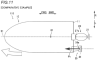
- the auxiliary propulsion device 30 is provided to one side of the centerline of the hull 10 in the right-left direction, and thus the marine vessel 110 is turned when a thrust P is generated in the forward-rearward direction from the auxiliary propulsion device 30 as in a comparative example shown in FIG. 11 . Therefore, as shown in FIG.
- the rudder angle change control is performed to change the rudder angle A of the auxiliary propulsion device 30 by the predetermined angle ⁇ to one side (L side) in the right-left direction of the hull 10 with respect to the forward-rearward direction of the hull 10 such that the rudder angle A of the auxiliary propulsion device 30 is changed to generate a thrust from the auxiliary propulsion device 30 so as to move the marine vessel 110 in the forward-rearward direction.
- the predetermined angle ⁇ that causes the auxiliary propulsion device 30 to generate a thrust to move the marine vessel 110 in the forward-rearward direction varies depending on the shape and size of the hull 10, the attachment position of the auxiliary propulsion device 30 to the hull 10, etc. Therefore, the controller 50 (see FIG. 1 ) performs a calibration control to adjust the predetermined angle ⁇ according to the hull 10. Specifically, in the marine vessel 110 in which the calibration control is not performed, the user operates the operator 40 to move the marine vessel 110 in the forward-rearward direction. Then, while the marine vessel 110 is moved in the forward-rearward direction, an operation is performed (a calibration button is pressed, for example) to memorize the state of the operator 40.
- the controller 50 performs the rudder angle change control to change the rudder angle A of the auxiliary propulsion device 30 by a calibrated predetermined angle ⁇ with respect to the marine vessel 110.
- the marine propulsion system 100 (marine vessel 110) includes the controller 50 configured or programmed to perform the electric drive control to cause the electric motor 32 to drive the auxiliary propeller 31 having a minimum output smaller than the minimum output of the main propeller 21 in the auxiliary propulsion device 30 without performing the engine drive control to cause the engine 22 to drive the main propeller 21 in the main propulsion device 20 when adjusting the thrust P of the marine vessel 110 to less than the troll thrust P trl .
- the electric drive control is performed without performing the engine drive control such that the thrust P of the marine vessel 110 is changed to less than the troll thrust P trl without alternately repeating the shift-in state and the neutral state of the main propulsion device 20 at predetermined time intervals. Consequently, the speed V of the marine vessel 110 is stabilized when the marine vessel 110 navigates at a speed lower than the speed V in the troll thrust P trl state (troll speed V trl ).
- the shift-in state and the neutral state of the main propulsion device 20 are not alternately repeated at the predetermined time intervals, and thus noises and vibrations are not generated when the main propulsion device 20 is switched between the shift-in state and the neutral state. Consequently, the quietness of the marine vessel 110 is improved when the marine vessel 110 navigates at a speed lower than the speed V in the troll thrust P trl state (troll speed V trl ).
- the electric motor 32 does not directly emit carbon dioxide, and thus the electric drive control is performed without performing the engine drive control when the thrust P of the marine vessel 110 is adjusted to less than the troll thrust P trl such that the amount of carbon dioxide emissions is reduced as compared with a case in which the engine drive control is performed when the thrust P of the marine vessel 110 is adjusted to less than the troll thrust P trl . Consequently, when the marine vessel 110 navigates at a speed lower than the speed V in the troll thrust P trl state (troll speed V trl ), the speed V of the marine vessel 110 is stabilized, the quietness of the marine vessel 110 is improved, and the amount of carbon dioxide emissions is reduced.
- the main propulsion device 20 is provided on the centerline 91 of the hull 10 in the right-left direction. Furthermore, the auxiliary propulsion device 30 is provided to one side of the centerline of the hull 10 in the right-left direction. Accordingly, in a structure including the main propulsion device 20 and the auxiliary propulsion device 30 that have different minimum outputs and are not provided symmetrically with each other, when the marine vessel 110 navigates at a speed lower than the speed V in the troll thrust P trl state (troll speed V trl ), the speed V of the marine vessel 110 is stabilized, the quietness of the marine vessel 110 is improved, and the amount of carbon dioxide emissions is reduced.
- the controller 50 is configured or programmed to perform the electric drive control to continuously drive the auxiliary propeller 31 without performing the engine drive control when adjusting the thrust P of the marine vessel 110 to less than the troll thrust P trl . Accordingly, when the thrust P of the marine vessel 110 is adjusted to less than the troll thrust P trl , the auxiliary propeller 31 is continuously driven such that the thrust P of the marine vessel 110 is stably generated as compared with a case in which the auxiliary propeller 31 is not continuously driven. Consequently, the speed V of the marine vessel 110 is reliably stabilized when the marine vessel 110 navigates at a speed lower than the speed V in the troll thrust P trl state (troll speed V trl ).
- the controller 50 is configured or programmed to perform the engine drive control without performing the electric drive control when adjusting the thrust P of the marine vessel 110 to the troll thrust P trl or more. Accordingly, in a structure in which the engine drive control is performed without performing the electric drive control when the thrust P of the marine vessel 110 is adjusted to the troll thrust P trl or more, the electric drive control is performed without performing the engine drive control when the thrust P of the marine vessel 110 is adjusted to less than the troll thrust P trl .
- the controller 50 is configured or programmed to perform the electric drive control such that any one of the speed V of the marine vessel 110, the rotation speed of the electric motor 32, and the output T2 of the electric motor 32 becomes the target value when adjusting the thrust P of the marine vessel 110 to less than the troll thrust P trl . Accordingly, any one of the speed V of the marine vessel 110, the rotation speed of the electric motor 32, and the output T2 of the electric motor 32 is easily adjusted as the target value of the thrust P of the marine vessel 110 such that the thrust P of the marine vessel 110 becomes less than the troll thrust P trl .
- the controller 50 is configured or programmed to adjust the target value of any one of the speed V of the marine vessel 110, the rotation speed of the electric motor 32, and the output T2 of the electric motor 32 in a plurality of stages when adjusting the thrust P of the marine vessel 110 to less than the troll thrust P trl . Accordingly, any one of the speed V of the marine vessel 110, the rotation speed of the electric motor 32, and the output T2 of the electric motor 32 is adjusted as the target value of the thrust P of the marine vessel 110 in the plurality of stages such that the thrust P of the marine vessel 110 is adjusted to a desired value less than the troll thrust P trl .
- the controller 50 is configured or programmed to perform the electric drive control such that any one of the speed V of the marine vessel 110, the rotation speed of the electric motor 32, and the output T2 of the electric motor 32 becomes the target value when adjusting the thrust P of the marine vessel 110 to less than the troll thrust P trl in the automatic navigation mode in which navigation of the marine vessel 110 is automatically controlled. Accordingly, the marine vessel 110 is automatically navigated while any one of the speed V of the marine vessel 110, the rotation speed of the electric motor 32, and the output T2 of the electric motor 32 is adjusted as the target value of the thrust P of the marine vessel 110 such that the thrust P of the marine vessel 110 becomes less than the troll thrust P trl .
- the auxiliary propulsion device 30 is provided to one side of the centerline of the hull 10 in the right-left direction. Furthermore, the controller 50 is configured or programmed to perform the rudder angle change control to change the rudder angle A of the auxiliary propulsion device 30 by the predetermined angle ⁇ to one side in the right-left direction of the hull 10 with respect to the forward-rearward direction of the hull 10 so as to move the marine vessel 110 in the forward-rearward direction when the marine vessel 110 is moved in the forward-rearward direction by the electric drive control.
- the rudder angle change control is performed such that check helm is automatically performed to reduce or prevent rotation of the marine vessel 110 due to the auxiliary propulsion device 30 being provided to one side of the centerline of the hull 10 in the right-left direction. Consequently, when the marine vessel 110 is moved in the forward-rearward direction by the electric drive control, the marine vessel 110 is navigated as intended by the user.
- the controller 50 is configured or programmed to perform the calibration control to adjust the predetermined angle ⁇ according to the marine vessel 110. Accordingly, the calibration control is performed such that the predetermined angle ⁇ by which the rudder angle A of the auxiliary propulsion device 30 is turned to move the marine vessel 110 in the forward-rearward direction when the marine vessel 110 is moved in the forward-rearward direction by the electric drive control is adjusted according to the shape and size of the hull 10, the attachment positions of the main propulsion device 20 and the auxiliary propulsion device 30 to the hull 10, etc.
- the main propulsion device 20 is an engine outboard motor including the engine 22 to drive the main propeller 21 corresponding to a main thruster and provided on the centerline 91 of the hull 10 in the right-left direction.
- the auxiliary propulsion device 30 is an electric outboard motor including the electric motor 32 to drive the auxiliary propeller 31 corresponding to an auxiliary thruster and provided to one side of the centerline 91 of the hull 10 in the right-left direction.
- the main propulsion device 20 and the auxiliary propulsion device 30 are an engine outboard motor and an electric outboard motor, respectively, when the marine vessel 110 navigates at a speed lower than the speed V in the troll thrust P trl state (troll speed V trl ), the speed V of the marine vessel 110 is stabilized, the quietness of the marine vessel 110 is improved, and the amount of carbon dioxide emissions is reduced.
- main propulsion device 20 is preferably an engine outboard motor
- auxiliary propulsion device 30 is preferably an electric outboard motor in preferred embodiments described above
- the present teaching is not restricted to this.
- the main propulsion device and the auxiliary propulsion device may alternatively be inboard motors enclosed within the hull instead of outboard motors, or inboard-outboard motors partially enclosed within the hull.
- the controller 50 preferably performs the calibration control to adjust the predetermined angle ⁇ according to the marine vessel 110 in preferred embodiments described above, the present teaching is not restricted to this.
- the controller may not perform the calibration control to adjust the predetermined angle according to the marine vessel.
- the rudder angle of the auxiliary propulsion device may be manually set by the user when the marine vessel is moved in the forward-rearward direction by the electric drive control, for example.
- While the controller 50 preferably performs the rudder angle change control to change the rudder angle A of the auxiliary propulsion device 30 by the predetermined angle ⁇ to one side in the right-left direction of the hull 10 with respect to the forward-rearward direction of the hull 10 so as to move the marine vessel 110 in the forward-rearward direction when the marine vessel 110 is moved in the forward-rearward direction by the electric drive control in preferred embodiments described above, the present teaching is not restricted to this.
- the controller may not perform the rudder angle change control to change the rudder angle of the auxiliary propulsion device by the predetermined angle to one side in the right-left direction of the hull with respect to the forward-rearward direction of the hull so as to move the marine vessel in the forward-rearward direction when the marine vessel is moved in the forward-rearward direction by the electric drive control.
- the marine vessel in the marine propulsion system, the marine vessel may be moved in the forward-rearward direction by the electric drive control by a user's manual operation, for example.
- controller 50 preferably performs a control to transition the navigation mode from the manual navigation mode to the automatic navigation mode when the DOWN button 41d is pressed in the manual navigation mode in preferred embodiments described above, the present teaching is not restricted to this.
- the controller may alternatively perform a control to transition the navigation mode from the manual navigation mode to the automatic navigation mode when a portion (such as the UP button, a portion of the remote control lever other than the DOWN button and the UP button, or an operator other than the remote control lever) other than the DOWN button is operated in the manual navigation mode.
- the controller 50 preferably performs a control to maintain the speed V of the marine vessel 110 at the target value set by the user based on a user's operation on the UP button 41c or the DOWN button 41d in the automatic navigation mode in preferred embodiments described above, the present teaching is not restricted to this.
- the controller may alternatively perform a control to maintain the speed of the marine vessel at the target value set by the user based on a user's operation on a portion (such as a portion of the remote control lever other than the DOWN button and the UP button or an operator other than the remote control lever) other than the UP button and the DOWN button in the automatic navigation mode.
- the controller 50 preferably performs the electric drive control such that any one of the speed V of the marine vessel 110, the rotation speed of the electric motor 32, and the output T2 of the electric motor 32 becomes the target value when the thrust P of the marine vessel 110 is adjusted to less than the troll thrust P trl in the automatic navigation mode in which navigation of the marine vessel 110 is automatically controlled in preferred embodiments described above, the present teaching is not restricted to this.
- the controller may alternatively perform the electric drive control such that any one of the speed of the marine vessel, the rotation speed of the electric motor, and the output of the electric motor becomes the target value when the thrust of the marine vessel is adjusted to less than the troll thrust in the manual navigation mode in which the marine vessel is manually navigated.
- the thrust P of the marine vessel 110 is preferably settable in ten stages between the troll thrust P trl and the minimum thrust P min in preferred embodiments described above, the present teaching is not restricted to this.
- the thrust of the marine vessel may alternatively be settable in any of two to nine stages between the troll thrust and the minimum thrust or in eleven or more stages between the troll thrust and the minimum thrust.
- the controller 50 is preferably able to adjust the target value of any one of the speed V of the marine vessel 110, the rotation speed of the electric motor 32, and the output T2 of the electric motor 32 in a plurality of stages when adjusting the thrust P of the marine vessel 110 to less than the troll thrust P trl in preferred embodiments described above, the present teaching is not restricted to this.
- the controller may alternatively be able to adjust the target value of any one of the speed of the marine vessel, the rotation speed of the electric motor, and the output of the electric motor in only one stage when adjusting the thrust of the marine vessel to less than the troll thrust.
- controller 50 preferably performs the engine drive control without performing the electric drive control when adjusting the thrust P of the marine vessel 110 to the troll thrust P trl or more in preferred embodiments described above, the present teaching is not restricted to this.
- the controller may alternatively perform both the engine drive control and the electric drive control or may alternatively perform the electric drive control without performing the engine drive control when adjusting the thrust of the marine vessel to the troll thrust or more.
- auxiliary propulsion device 30 is preferably provided to the L side (port side) of the hull 10 in preferred embodiments described above, the present teaching is not restricted to this. In the present teaching, the auxiliary propulsion device may alternatively be provided to the starboard side of the hull.
- the present teaching is not restricted to this.
- the main propulsion device may alternatively be provided to one side of the centerline of the hull in the right-left direction
- the auxiliary propulsion device may alternatively be provided on the centerline of the hull in the right-left direction.
- main propulsion device 20 is preferably attached to the stern 11 of the hull 10 in preferred embodiments described above, the present teaching is not restricted to this. In the present teaching, two or more main propulsion devices may alternatively be attached to the stern of the hull.
- auxiliary propulsion device 30 is preferably attached to the stern 11 of the hull 10 in preferred embodiments described above, the present teaching is not restricted to this. In the present teaching, two or more auxiliary propulsion devices may alternatively be attached to the stern of the hull.
- main propulsion device 20 is preferably steerable by about 30 degrees to each of the L side (the port side of the marine vessel 110) and the R side (the starboard side of the marine vessel 110) in preferred embodiments described above, the present teaching is not restricted to this.
- the main propulsion device may alternatively be steerable by an angle other than about 30 degrees to each of the port side and the starboard side of the marine vessel.
- auxiliary propulsion device 30 is preferably steerable by about 70 degrees to each of the L side (the port side of the marine vessel 110) and the R side (the starboard side of the marine vessel 110) in preferred embodiments described above, the present teaching is not restricted to this. In the present teaching, the auxiliary propulsion device may alternatively be steerable by an angle other than about 70 degrees to each of the port side and the starboard side of the marine vessel.
Landscapes
- Engineering & Computer Science (AREA)
- Chemical & Material Sciences (AREA)
- Combustion & Propulsion (AREA)
- Mechanical Engineering (AREA)
- Ocean & Marine Engineering (AREA)
- Aviation & Aerospace Engineering (AREA)
- Radar, Positioning & Navigation (AREA)
- Remote Sensing (AREA)
- Physics & Mathematics (AREA)
- General Physics & Mathematics (AREA)
- Automation & Control Theory (AREA)
- Control Of Vehicle Engines Or Engines For Specific Uses (AREA)
Abstract
Description
- The present invention relates to a marine propulsion system, and more particularly, it relates to a marine propulsion system that is able to adjust the thrust of a marine vessel to less than a troll thrust, which is a minimum thrust generated when an engine continuously drives a thruster. It also relates to a marine vessel comprising such a marine propulsion system.
- A marine vessel that is able to adjust the thrust of the marine vessel to less than a troll thrust, which is a minimum thrust generated when an engine continuously drives a thruster is known in general. Such a marine vessel is disclosed in
JP 6 156 926 B2 -
JP 6 156 926 B2 JP 6 156 926 B2 JP 6 156 926 B2 - When the marine vessel described in
JP 6 156 926 B2 - It is an object of the present invention to provide a marine propulsion system that stabilizes the speed of a marine vessel and improves the quietness of the marine vessel when the marine vessel navigates at a speed lower than a speed in a troll thrust state, and reduces the amount of carbon dioxide emissions. According to the present invention, said object is solved by a marine propulsion system having the features of independent claim 1. Preferred embodiments are laid down in the dependent claims.
- A marine propulsion system according to the present invention comprises a main propulsion device configured to be attached to a stern of a hull, including an engine configured to drive a main thruster to generate a thrust, and configured to rotate in a right-left direction to change a direction of the thrust, an auxiliary propulsion device configured to be attached to the stern, including an electric motor configured to drive an auxiliary thruster to generate a thrust, configured to rotate in the right-left direction to change a direction of the thrust, and having a minimum output smaller than a minimum output of the main propulsion device, and a controller configured or programmed to perform an electric drive control to cause the electric motor to drive the auxiliary thruster in the auxiliary propulsion device without performing an engine drive control to cause the engine to drive the main thruster in the main propulsion device when adjusting a thrust of a marine vessel to less than a troll thrust corresponding to a minimum thrust generated when the engine continuously drives the main thruster.
- A marine propulsion system according to the present invention includes the controller configured or programmed to perform the electric drive control to cause the electric motor to drive the auxiliary thruster having a minimum output smaller than the minimum output of the main thruster in the auxiliary propulsion device without performing the engine drive control to cause the engine to drive the main thruster in the main propulsion device when adjusting the thrust of the marine vessel to less than the troll thrust. Accordingly, when the thrust of the marine vessel is adjusted to less than the troll thrust, the electric drive control is performed without performing the engine drive control such that the thrust of the marine vessel is changed to less than the troll thrust without alternately repeating the shift-in state and the neutral state of the main propulsion device at predetermined time intervals. Consequently, the speed of the marine vessel is stabilized when the marine vessel navigates at a speed lower than a speed in the troll thrust state. Furthermore, when the thrust of the marine vessel is adjusted to less than the troll thrust, the shift-in state and the neutral state of the main propulsion device are not alternately repeated at the predetermined time intervals, and thus noises and vibrations are not generated when the main propulsion device is switched between the shift-in state and the neutral state. Consequently, the quietness of the marine vessel is improved when the marine vessel navigates at a speed lower than the speed in the troll thrust state. In addition, unlike the engine, the electric motor does not directly emit carbon dioxide, and thus the electric drive control is performed without performing the engine drive control when the thrust of the marine vessel is adjusted to less than the troll thrust such that the amount of carbon dioxide emissions is reduced as compared with a case in which the engine drive control is performed when the thrust of the marine vessel is adjusted to less than the troll thrust. Consequently, when the marine vessel navigates at a speed lower than the speed in the troll thrust state, the speed of the marine vessel is stabilized, the quietness of the marine vessel is improved, and the amount of carbon dioxide emissions is reduced.
- In a marine propulsion system according to a preferred embodiment, the main propulsion device is preferably configured to be provided on a centerline of the hull in the right-left direction, and the auxiliary propulsion device is preferably configured to be provided to one side of the centerline of the hull in the right-left direction. Accordingly, in a structure including the main propulsion device and the auxiliary propulsion device that have different minimum outputs and are not provided symmetrically with each other, when the marine vessel navigates at a speed lower than the speed in the troll thrust state, the speed of the marine vessel is stabilized, the quietness of the marine vessel is improved, and the amount of carbon dioxide emissions is reduced.
- In a marine propulsion system according to a preferred embodiment, the controller is preferably configured or programmed to perform the electric drive control to continuously drive the auxiliary thruster without performing the engine drive control when adjusting the thrust of the marine vessel to less than the troll thrust. Accordingly, when the thrust of the marine vessel is adjusted to less than the troll thrust, the auxiliary thruster is continuously driven such that the thrust of the marine vessel is stably generated as compared with a case in which the auxiliary thruster is not continuously driven. Consequently, the speed of the marine vessel is reliably stabilized when the marine vessel navigates at a speed lower than the speed in the troll thrust state.
- In a marine propulsion system according to a preferred embodiment, the controller is preferably configured or programmed to perform the engine drive control without performing the electric drive control, perform both the engine drive control and the electric drive control, or perform the electric drive control without performing the engine drive control when adjusting the thrust of the marine vessel to the troll thrust or more. Accordingly, in a structure in which the engine drive control is performed without performing the electric drive control, both the engine drive control and the electric drive control are performed, or the electric drive control is performed without performing the engine drive control when the thrust of the marine vessel is adjusted to the troll thrust or more, the electric drive control is performed without performing the engine drive control when the thrust of the marine vessel is adjusted to less than the troll thrust.
- In a marine propulsion system according to a preferred embodiment, the controller is preferably configured or programmed to perform the electric drive control such that any one of a speed of the marine vessel, a rotation speed of the electric motor, and an output of the electric motor becomes a target value when adjusting the thrust of the marine vessel to less than the troll thrust. Accordingly, any one of the speed of the marine vessel, the rotation speed of the electric motor, and the output of the electric motor is easily adjusted as the target value of the thrust of the marine vessel such that the thrust of the marine vessel becomes less than the troll thrust.
- In such a case, the controller is preferably configured or programmed to adjust the target value of any one of the speed of the marine vessel, the rotation speed of the electric motor, and the output of the electric motor in a plurality of stages when adjusting the thrust of the marine vessel to less than the troll thrust. Accordingly, any one of the speed of the marine vessel, the rotation speed of the electric motor, and the output of the electric motor is adjusted as the target value of the thrust of the marine vessel in the plurality of stages such that the thrust of the marine vessel is adjusted to a desired value less than the troll thrust.
- In a marine propulsion system including the controller configured or programmed to perform the electric drive control such that any one of the speed of the marine vessel, the rotation speed of the electric motor, and the output of the electric motor becomes the target value when adjusting the thrust of the marine vessel to less than the troll thrust, the controller is preferably configured or programmed to perform the electric drive control such that any one of the speed of the marine vessel, the rotation speed of the electric motor, and the output of the electric motor becomes the target value when adjusting the thrust of the marine vessel to less than the troll thrust in an automatic navigation mode in which navigation of the marine vessel is automatically controlled. Accordingly, the marine vessel is automatically navigated while any one of the speed of the marine vessel, the rotation speed of the electric motor, and the output of the electric motor is adjusted as the target value of the thrust of the marine vessel such that the thrust of the marine vessel becomes less than the troll thrust.
- In a marine propulsion system according to a preferred embodiment, the auxiliary propulsion device is preferably configured to be provided to one side of the hull in the right-left direction, and the controller is preferably configured or programmed to perform a rudder angle change control to change a rudder angle of the auxiliary propulsion device by a predetermined angle to one side in the right-left direction of the hull with respect to a forward-rearward direction of the hull so as to move the marine vessel in the forward-rearward direction when the marine vessel is moved in the forward-rearward direction by the electric drive control. Accordingly, when the marine vessel is moved in the forward-rearward direction by the electric drive control, the rudder angle change control is performed such that check helm is automatically performed to reduce or prevent rotation of the marine vessel due to the auxiliary propulsion device being provided to one side of the centerline of the hull in the right-left direction. Consequently, when the marine vessel is moved in the forward-rearward direction by the electric drive control, the marine vessel is navigated as intended by a user.
- In such a case, the controller is preferably configured or programmed to perform a calibration control to adjust the predetermined angle according to at least one of a shape of the hull, a size of the hull, or attachment positions of the main propulsion device and the auxiliary propulsion device to the hull. Accordingly, the calibration control is performed such that the predetermined angle by which the rudder angle of the auxiliary propulsion device is turned to move the marine vessel in the forward-rearward direction when the marine vessel is moved in the forward-rearward direction by the electric drive control is adjusted according to the shape of the hull, the size of the hull, and/or the attachment positions of the main propulsion device and the auxiliary propulsion device to the hull, etc.
- In a marine propulsion system according to a preferred embodiment, the main propulsion device is preferably an engine outboard motor including the engine configured to drive a main propeller corresponding to the main thruster and configured to be provided on a centerline of the hull in the right-left direction, and the auxiliary propulsion device is preferably an electric outboard motor including the electric motor configured to drive an auxiliary propeller corresponding to the auxiliary thruster and configured to be provided to one side of the centerline of the hull in the right-left direction. Accordingly, in a structure in which the main propulsion device and the auxiliary propulsion device are an engine outboard motor and an electric outboard motor, respectively, when the marine vessel navigates at a speed lower than the speed in the troll thrust state, the speed of the marine vessel is stabilized, the quietness of the marine vessel is improved, and the amount of carbon dioxide emissions is reduced.
- The above and other elements, features, steps, characteristics and advantages of preferred embodiments will become more apparent from the following detailed description of the preferred embodiments with reference to the attached drawings.
-
-
FIG. 1 is a block diagram showing a marine propulsion system according to a preferred embodiment. -
FIG. 2 is a schematic view showing a marine vessel according to a preferred embodiment. -
FIG. 3 is a side view showing a main propulsion device of a marine vessel according to a preferred embodiment. -
FIG. 4 is a side view showing an auxiliary propulsion device of a marine vessel according to a preferred embodiment. -
FIG. 5 is a diagram showing a power range of an engine of a main propulsion device and a power range of an electric motor of an auxiliary propulsion device according to a preferred embodiment. -
FIG. 6 is a diagram showing a remote control of a marine vessel according to a preferred embodiment. -
FIG. 7 is a diagram showing a joystick of a marine vessel according to a preferred embodiment. -
FIG. 8 is a diagram illustrating a relationship between the thrust of a marine vessel, the speed of the marine vessel, and driving of main and auxiliary propulsion drives in a marine propulsion system according to a preferred embodiment. -
FIG. 9 is a schematic view showing a hull navigating under an engine drive control in a marine propulsion system according to a preferred embodiment. -
FIG. 10 is a schematic view showing a hull navigating under an electric drive control in a marine propulsion system according to a comparative example. -
FIG. 11 is a schematic view showing a hull navigating under an electric drive control in a marine propulsion system according to a comparative example. - Preferred embodiments are hereinafter described with reference to the drawings.
- The structures of a
marine propulsion system 100 and amarine vessel 110 according to preferred embodiments are now described with reference toFIGS. 1 to 10 . In the figures, arrow FWD represents the front of themarine vessel 110, arrow BWD represents the rear of themarine vessel 110, arrow L represents the left (port side) of themarine vessel 110, and arrow R represents the right (starboard side) of themarine vessel 110. - As shown in
FIG. 1 , themarine vessel 110 includes ahull 10 and themarine propulsion system 100. Themarine propulsion system 100 is provided on or in thehull 10. Themarine propulsion system 100 propels themarine vessel 110. Themarine vessel 110 may be a relatively small marine vessel used for sightseeing or fishing, for example. - The
marine propulsion system 100 includes amain propulsion device 20, anauxiliary propulsion device 30, anoperator 40, acontroller 50, and adisplay 60. Theoperator 40, thecontroller 50, and thedisplay 60 are provided on or in thehull 10. - As shown in
FIG. 2 , only onemain propulsion device 20 is attached to a stern 11 of thehull 10. That is, themain propulsion device 20 is an outboard motor. Themain propulsion device 20 is located on acenterline 91 of thehull 10 in a right-left direction. Thecenterline 91 of thehull 10 in the right-left direction extends through the center ofgravity 81 of thehull 10. - As shown in
FIG. 3 , themain propulsion device 20 includes a mainpropulsion device body 20a and abracket 20b. The mainpropulsion device body 20a is attached to the stern 11 of thehull 10 via thebracket 20b. - The
main propulsion device 20 includes anengine 22 to drive amain propeller 21 to generate a thrust. That is, themain propulsion device 20 is an engine outboard motor including theengine 22 to drive themain propeller 21. Specifically, the mainpropulsion device body 20a includes theengine 22, adrive shaft 23, agearing 24, apropeller shaft 25, and themain propeller 21. Theengine 22 is an internal combustion engine that generates a driving force. The driving force of theengine 22 is transmitted to themain propeller 21 via thedrive shaft 23, thegearing 24, and thepropeller shaft 25. Themain propeller 21 generates a thrust by rotating in the water by the driving force transmitted from theengine 22. Themain propeller 21 is an example of a "main thruster". - The main
propulsion device body 20a includes ashift actuator 26 to switch the shift state (the forward movement state, the reverse movement state, or the neutral state) of themain propulsion device 20. Theshift actuator 26 switches the shift state of themain propulsion device 20 between the forward movement state (shift-in state), the reverse movement state (shift-in state), and the neutral state by switching the meshing of thegearing 24. In the forward movement state, a driving force is transmitted from theengine 22 to themain propeller 21 to generate a forward thrust from themain propeller 21. In the reverse movement state, a driving force is transmitted from theengine 22 to themain propeller 21 to generate a reverse thrust from themain propeller 21. In the neutral state, a driving force is not transmitted from theengine 22 to themain propeller 21 in order to not generate a thrust from themain propeller 21. In themain propulsion device 20, when the shift state of themain propulsion device 20 is switched, thegearing 24 generates relatively loud noises and vibrations. - The
main propulsion device 20 rotates in the right-left direction to change the direction of a thrust. Specifically, asteering 27 is provided on thebracket 20b. The steering 27 includes asteering shaft 27a that extends in an upward-downward direction. The mainpropulsion device body 20a is rotated in the right-left direction by the steering 27 about thesteering shaft 27a with respect to thebracket 20b. When the mainpropulsion device body 20a rotates in the right-left direction about thesteering shaft 27a, the orientation of themain propeller 21 also rotates in the right-left direction. Thus, the direction of the thrust of themain propeller 21 is changed. In the following description, changing the direction of the thrust of themain propeller 21 by rotating the orientation of themain propeller 21 in the right-left direction is referred to as "steering themain propulsion device 20". - As shown in
FIG. 2 , themain propulsion device 20 is steerable by about 30 degrees to each of the L side and the R side. That is, a steering angle range A10, which is an angular range in which themain propulsion device 20 is steerable, is about 60 degrees. - As shown in
FIG. 1 , themain propulsion device 20 includes an engine control unit (ECU) 28 and a steering control unit (SCU) 29. TheECU 28 controls driving of theengine 22 and driving of theshift actuator 26 based on a control performed by thecontroller 50. TheSCU 29 controls driving of the steering 27 based on a control performed by thecontroller 50. TheECU 28 and theSCU 29 include a control circuit including a central processing unit (CPU), for example. - As shown in
FIG. 2 , only oneauxiliary propulsion device 30 is attached to the stern 11 of thehull 10. That is, theauxiliary propulsion device 30 is an outboard motor. Theauxiliary propulsion device 30 is provided to one side of thecenterline 91 of thehull 10 in the right-left direction. In themarine propulsion system 100, theauxiliary propulsion device 30 is provided to the L side of thehull 10. - As shown in
FIG. 4 , theauxiliary propulsion device 30 includes acowling 30a, anupper case 30b, alower case 30c, and aduct 30d. Thecowling 30a, theupper case 30b, thelower case 30c, and theduct 30d are aligned in this order from top to bottom. Thecowling 30a is attached to the stern 11 of thehull 10. - The
auxiliary propulsion device 30 includes anelectric motor 32 to drive anauxiliary propeller 31 to generate a thrust. That is, theauxiliary propulsion device 30 is an electric outboard motor including theelectric motor 32 to drive theauxiliary propeller 31. Specifically, theauxiliary propulsion device 30 includes theelectric motor 32 and theauxiliary propeller 31. Theelectric motor 32 is provided in theduct 30d. Theauxiliary propeller 31 is provided in theduct 30d. Theelectric motor 32 is driven by power supplied from a battery (not shown) provided in thehull 10. Theelectric motor 32 includes astator 32a that is integral and unitary with theduct 30d, and a rotor 32b that is integral and unitary with theauxiliary propeller 31. Theauxiliary propeller 31 generates a thrust by rotating in the water by a driving force transmitted from theelectric motor 32. Theauxiliary propeller 31 is an example of an "auxiliary thruster". - When the
auxiliary propeller 31 is rotated forward, a forward thrust is generated from theauxiliary propeller 31. That is, when theauxiliary propeller 31 is rotated forward, the shift state of theauxiliary propulsion device 30 becomes a forward movement state. When theauxiliary propeller 31 is rotated backward, a reverse thrust is generated from theauxiliary propeller 31. That is, when theauxiliary propeller 31 is rotated backward, the shift state of theauxiliary propulsion device 30 becomes a reverse movement state. When theauxiliary propeller 31 is stopped, a thrust is not generated from theauxiliary propeller 31. That is, when theauxiliary propeller 31 is stopped, the shift state of theauxiliary propulsion device 30 becomes a neutral state. Therefore, when the shift state (the forward movement state, the reverse movement state, or the neutral state) of theauxiliary propulsion device 30 is changed, the meshing of the gearing 24 (seeFIG. 3 ) is not switched unlike when the shift state of the main propulsion unit 20 (seeFIG. 3 ) is switched. Thus, when the shift state of theauxiliary propulsion device 30 is changed, theauxiliary propulsion device 30 does not generate relatively loud noises or vibrations unlike when the shift state of themain propulsion device 20 is switched. - The
auxiliary propulsion device 30 rotates in the right-left direction to change the direction of a thrust. Specifically, asteering 33 is provided in theauxiliary propulsion device 30. The steering 33 includes asteering shaft 33a fixed to thelower case 30c and extending in the upward-downward direction. An upper end of thesteering shaft 33a is located in theupper case 30b. A lower end of thesteering shaft 33a is fixed to theduct 30d. Theduct 30d and thelower case 30c are rotatable in the right-left direction by the steering 33 about thesteering shaft 33a with respect to thecowling 30a and theupper case 30b. When theduct 30d rotates in the right-left direction about thesteering shaft 33a, the orientation of theauxiliary propeller 31 also rotates in the right-left direction. Thus, the direction of the thrust of theauxiliary propeller 31 is changed. In the following description, changing the direction of the thrust of theauxiliary propeller 31 by rotating the orientation of theauxiliary propeller 31 in the right-left direction is referred to as "steering theauxiliary propulsion device 30". - As shown in
FIG. 2 , theauxiliary propulsion device 30 is steerable by about 70 degrees to each of the L side and the R side. That is, a steering angle range A20, which is an angular range in which theauxiliary propulsion device 30 is steerable, is about 140 degrees. - As shown in
FIG. 1 , theauxiliary propulsion device 30 includes a motor control unit (MCU) 34 and a steering control unit (SCU) 35. TheMCU 34 and theSCU 35 include a control circuit including a CPU, for example. TheMCU 34 controls driving of theelectric motor 32 based on a control performed by thecontroller 50. TheSCU 35 controls driving of the steering 33 based on a control performed by thecontroller 50. - As shown in
FIG. 5 , the minimum output of theauxiliary propulsion device 30 is smaller than that of themain propulsion device 20. Specifically, the maximum value T11 and the minimum value T12 of the power range T10 of theengine 22 of themain propulsion device 20 are larger than the maximum value T21 and the minimum value T22 of the power range T20 of theelectric motor 32 of theauxiliary propulsion device 30, respectively. The minimum value T12 of the power range T10 of theengine 22 is smaller than the maximum value T21 of the power range T20 of theelectric motor 32. That is, the power range T10 of theengine 22 of themain propulsion device 20 and the power range T20 of theelectric motor 32 of theauxiliary propulsion device 30 overlap each other between the maximum value T21 of the power range T20 of theelectric motor 32 and the minimum value T12 of the power range T10 of theengine 22. - As shown in
FIG. 1 , theoperator 40 receives a user's operation in order to operate (maneuver) themarine vessel 110. Theoperator 40 includes aremote control 41, asteering wheel 42, and ajoystick 43. - When the
marine propulsion system 100 is in a non-joystick mode, an operation on thejoystick 43 is not received, but operations on theremote control 41 and thesteering wheel 42 are received. When themarine propulsion system 100 is in a joystick mode, operations on theremote control 41 and thesteering wheel 42 are not received, but an operation on thejoystick 43 is received. - As shown in
FIG. 6 , theremote control 41 includes abase 41a and alever 41b. Thelever 41b is attached to thebase 41a so as to be tiltable in a forward-rearward direction. When thelever 41b is tilted, at least one of the ECU 28 (seeFIG. 1 ) of the main propulsion device 20 (seeFIG. 1 ) or the MCU 34 (seeFIG. 1 ) of the auxiliary propulsion device 30 (seeFIG. 1 ) is controlled by the controller 50 (seeFIG. 1 ). - The position of the
lever 41b between a position tilted forward by a predetermined angle and a position tilted rearward by a predetermined angle is set as a neutral position (N) corresponding to the neutral state of the shift state of the main propulsion device 20 (seeFIG. 1 ). The position of thelever 41b tilted forward from the neutral position (N) is set as a forward movement position (F) corresponding to the forward movement state of the shift state of themain propulsion device 20. The position of thelever 41b tilted rearward from the neutral position (N) is set as a reverse movement position (R) corresponding to the reverse movement state of the shift state of themain propulsion device 20. The magnitude of the tilt angle of thelever 41b at the forward movement position (F) and the reverse movement position (R) corresponds to the magnitude of the output T1 (seeFIG. 5 ) of the engine 22 (seeFIG. 1 ) of themain propulsion device 20. - When the
lever 41b is operated so as to be located at the neutral position (N) in a manual navigation mode, the controller 50 (seeFIG. 1 ) performs a control such that the shift state of the main propulsion device 20 (seeFIG. 1 ) becomes the neutral state. When thelever 41b is operated so as to be located at the forward movement position (F) in the manual navigation mode, thecontroller 50 performs a control such that the shift state of themain propulsion device 20 becomes the forward movement state (shift-in state). When thelever 41b is operated so as to be located at the reverse movement position (R) in the manual navigation mode, thecontroller 50 performs a control such that the shift state of themain propulsion device 20 becomes the reverse movement state (shift-in state). The manual navigation mode refers to an operation mode in which thecontroller 50 controls navigation of the marine vessel 110 (seeFIG. 1 ) based on a user's operation on the operator 40 (seeFIG. 1 ). For example, thecontroller 50 performs a control such that the speed V (seeFIG. 8 ) of themarine vessel 110 is changed based on a user's operation to change the tilt angle on thelever 41b. That is, the manual navigation mode is an operation mode in which navigation of themarine vessel 110 is manually controlled. - The
remote control 41 includes anUP button 41c and aDOWN button 41d. TheUP button 41c and theDOWN button 41d are provided for an automatic navigation mode. The automatic navigation mode refers to an operation mode in which the controller 50 (seeFIG. 1 ) automatically controls navigation of the marine vessel 110 (seeFIG. 1 ) based on a user's operation on the operator 40 (seeFIG. 1 ). For example, thecontroller 50 performs a control such that the speed V (seeFIG. 8 ) of themarine vessel 110 is maintained at a target value set by the user based on a user's operation on theUP button 41c or theDOWN button 41d in the automatic navigation mode. That is, the automatic navigation mode is an operation mode in which navigation of themarine vessel 110 is automatically controlled. - Specifically, when the
DOWN button 41d is pressed in the manual navigation mode, the controller 50 (seeFIG. 1 ) performs a control to transition the navigation mode of the marine vessel 110 (seeFIG. 1 ) from the manual navigation mode to the automatic navigation mode. In the marine propulsion system 100 (seeFIG. 1 ), when theDOWN button 41d is pressed while thelever 41b is located at the forward movement position (F) or the reverse movement position (R), the controller 50 (seeFIG. 1 ) performs a control to transition the navigation mode of themarine vessel 110 from the manual navigation mode to the automatic navigation mode. That is, when theDOWN button 41d is pressed while thelever 41b is located at the neutral position (N), thecontroller 50 does not perform a control to transition the navigation mode of themarine vessel 110 from the manual navigation mode to the automatic navigation mode. - When the
UP button 41c is pressed in the automatic navigation mode, the controller 50 (seeFIG. 1 ) performs a control to increase the thrust P (seeFIG. 8 ) of the marine vessel 110 (seeFIG. 1 ). When theDOWN button 41d is pressed in the automatic navigation mode, thecontroller 50 performs a control to reduce the thrust P of themarine vessel 110. In the marine propulsion system 100 (seeFIG. 1 ), when the tilt angle of thelever 41b is changed in the automatic navigation mode, thecontroller 50 performs a control to transition the automatic navigation mode to the manual navigation mode. That is, in the automatic navigation mode, thelever 41b is located at the forward movement position (F) or the reverse movement position (R). - Although not shown, the steering wheel 42 (see
FIG. 1 ) is rotatable. When thesteering wheel 42 is rotated, at least one of the SCU 29 (seeFIG. 1 ) of the main propulsion device 20 (seeFIG. 1 ) or the SCU 35 (seeFIG. 1 ) of the auxiliary propulsion device 30 (seeFIG. 1 ) is controlled by the controller 50 (seeFIG. 1 ). - As shown in
FIG. 7 , thejoystick 43 includes abase 43a and alever 43b. Thelever 43b is tiltably and rotatably attached to thebase 43a. Thelever 43b is urged by an urging member such as a spring to automatically return to a neutral position P10 when not operated by the user. At the neutral position P10, thelever 43b is upright and is not rotated. - When the
lever 43b is tilted, at least one of the ECU 28 (seeFIG. 1 ) of the main propulsion device 20 (seeFIG. 1 ), the SCU 29 (seeFIG. 1 ) of themain propulsion device 20, the MCU 34 (seeFIG. 1 ) of the auxiliary propulsion device 30 (seeFIG. 1 ), or the SCU 35 (seeFIG. 1 ) of theauxiliary propulsion device 30 is controlled by the controller 50 (seeFIG. 1 ) such that the marine vessel 110 (seeFIG. 1 ) is translated. When thelever 43b is tilted and rotated, at least one of theECU 28 of themain propulsion device 20, theSCU 29 of themain propulsion device 20, theMCU 34 of theauxiliary propulsion device 30, or theSCU 35 of theauxiliary propulsion device 30 is controlled by thecontroller 50 such that themarine vessel 110 is turned. When thelever 43b is rotated, at least one of theECU 28 of themain propulsion device 20, theSCU 29 of themain propulsion device 20, theMCU 34 of theauxiliary propulsion device 30, or theSCU 35 of theauxiliary propulsion device 30 is controlled by thecontroller 50 such that themarine vessel 110 is rotated. - A
joystick mode switch 43c is provided on thebase 43a of thejoystick 43. In themarine propulsion system 100, thejoystick mode switch 43c is pressed to switch between the joystick mode and the non-joystick mode. - As shown in
FIG. 1 , thecontroller 50 controls theECU 28 of themain propulsion device 20, theSCU 29 of themain propulsion device 20, theMCU 34 of theauxiliary propulsion device 30, and theSCU 29 of theauxiliary propulsion device 30 based on an operation on theoperator 40. Thecontroller 50 includes a control circuit including a CPU, for example. - The
display 60 displays information on themarine vessel 110. The information on themarine vessel 110 includes the speed V (seeFIG. 8 ) of themarine vessel 110, the output T1 (seeFIG. 5 ) of theengine 22 of themain propulsion device 20, the rotation speed of theengine 22 of themain propulsion device 20, the shift state (the forward movement state, the neutral state, or the reverse movement state) of themain propulsion device 20, the output T2 (seeFIG. 5 ) of theelectric motor 32 of theauxiliary propulsion device 30, the rotation speed of theelectric motor 32 of theauxiliary propulsion device 30, the shift state of theauxiliary propulsion device 30, and the navigation mode (the manual navigation mode or the automatic navigation mode) of themarine vessel 110, for example. Thedisplay 60 is a liquid crystal display, for example. - As shown in
FIG. 8 , the controller 50 (seeFIG. 1 ) performs an engine drive control without performing an electric drive control when adjusting the thrust P of themarine vessel 110 to a troll thrust Ptrl or more. Furthermore, thecontroller 50 performs the electric drive control without performing the engine drive control when adjusting the thrust P of themarine vessel 110 to less than the troll thrust Ptrl. The electric drive control refers to a control to cause theelectric motor 32 to continuously drive theauxiliary propeller 31 in theauxiliary propulsion device 30. The engine drive control refers to a control to cause theengine 22 to continuously drive themain propeller 21 in themain propulsion device 20. The troll thrust Ptrl refers to a minimum thrust P generated when theengine 22 continuously drives themain propeller 21. - Specifically, as shown in
FIG. 9 , the controller 50 (seeFIG. 1 ) stops theauxiliary propeller 31 of theauxiliary propulsion device 30 to not generate the output T2 (seeFIG. 5 ) of the auxiliary propulsion device 30 (not generate a thrust from the auxiliary propeller 31) when adjusting the thrust P (seeFig. 8 ) of themarine vessel 110 to the troll thrust Ptrl (seeFig. 8 ) or more. Furthermore, thecontroller 50 shifts themain propulsion device 20 into the shift-in state (forward or reverse movement state) and generates the output T1 (seeFIG. 5 ) of the main propulsion device 20 (generates a thrust from the main propeller 20) that is equal to or greater than an output in a troll thrust Ptrl state when adjusting the thrust P of themarine vessel 110 to the troll thrust Ptrl or more. That is, in themarine propulsion system 100, the thrust P of themarine vessel 110 is obtained from themain propulsion device 20 instead of theauxiliary propulsion device 30 when themarine vessel 110 navigates at a speed higher than a speed V in the troll thrust Ptrl state (troll speed Vtrl (seeFIG. 8 )).FIG. 9 shows a state in which the thrust P of themarine vessel 110 is P1 greater than the troll thrust Ptrl, and the speed V of themarine vessel 110 is V1 (seeFIG. 8 ) higher than the troll speed Vtrl. - On the other hand, as shown in
FIG. 10 , the controller 50 (seeFIG. 1 ) shifts themain propulsion device 20 into the neutral state to not generate the output T1 (seeFIG. 5 ) of the main propulsion device 20 (not generate a thrust from the main propeller 21) when adjusting the thrust P (seeFIG. 8 ) of themarine vessel 110 to less than the troll thrust Ptrl (seeFIG. 8 ). Furthermore, thecontroller 50 rotates theauxiliary propeller 31 of theauxiliary propulsion device 30 to generate the output T2 (seeFIG. 5 ) of the auxiliary propulsion device 30 (generate a thrust from the auxiliary propeller 31) when adjusting the thrust P of themarine vessel 110 to less than the troll thrust Ptrl. That is, in themarine propulsion system 100, the thrust P of themarine vessel 110 is obtained from theauxiliary propulsion device 30 instead of themain propulsion device 20 when themarine vessel 110 navigates at a speed lower than the speed V in the troll thrust Ptrl state (troll speed Vtrl (seeFIG. 8 )).FIG. 10 shows a state in which the thrust P of themarine vessel 110 is P2 smaller than the troll thrust Ptrl, and the speed V of themarine vessel 110 is V2 (seeFIG. 8 ) lower than the troll speed Vtrl. - As shown in
FIG. 8 , the controller 50 (seeFIG. 1 ) performs the electric drive control such that any one of the speed V of themarine vessel 110, the rotation speed of the electric motor 32 (seeFIG. 1 ), and the output T2 (seeFIG. 5 ) of theelectric motor 32 becomes a target value when adjusting the thrust P of themarine vessel 110 to less than the troll thrust Ptrl in the automatic navigation mode. In themarine propulsion system 100, a similar control is performed when the thrust P of themarine vessel 110 is adjusted to the troll thrust Ptrl or more. That is, thecontroller 50 performs the engine drive control such that any one of the speed V of themarine vessel 110, the rotation speed of the engine 22 (seeFIG. 1 ), and the output T1 (seeFIG. 5 ) of theengine 22 becomes a target value when adjusting the thrust P of themarine vessel 110 to the troll thrust Ptrl or more. - Specifically, in the automatic navigation mode, the user presses the UP button 41c (see
FIG. 6 ) and the DOWN button 41d (seeFIG. 6 ) of the remote control 41 (seeFIG. 6 ) such that any one of the speed V of the marine vessel 110, the rotation speed of the engine 22 (seeFIG. 1 ), and the output T1 (seeFIG. 5 ) of the engine 22 becomes the target value while checking any one of the speed V of the marine vessel 110, the rotation speed of the engine 22, and the output T1 of the engine 22 displayed on the display 60 (seeFIG. 1 ) when the thrust P of the marine vessel 110 is equal to or greater than the troll thrust Ptrl. After pressing the DOWN button 41d such that the thrust P of the marine vessel 110 is switched from the troll thrust Ptrl or more to the troll thrust Ptrl or less, the user presses the UP button 41c and the DOWN button 41d of the remote control 41 such that any one of the speed V of the marine vessel 110, the rotation speed of the electric motor 32, and the output T2 of the electric motor 32 becomes the target value while checking any one of the speed V of the marine vessel 110, the rotation speed of the electric motor 32, and the output T2 of the electric motor 32 displayed on the display 60 in a state in which the thrust P of the marine vessel 110 is less than the troll thrust Ptrl. - The
controller 50 is able to adjust the target value of any one of the speed V of themarine vessel 110, the rotation speed of the electric motor 32 (seeFIG. 1 ), and the output T2 (seeFIG. 5 ) of theelectric motor 32 in a plurality of stages when adjusting the thrust P of themarine vessel 110 to less than the troll thrust Ptrl. Specifically, in themarine propulsion system 100, the thrust P of themarine vessel 110 is settable in ten stages between the troll thrust Ptrl and a minimum thrust Pmin. In other words, the speed V of themarine vessel 110 is settable in ten stages between the troll speed Vtrl and a minimum speed Vmin, for example. - As shown in
FIG. 10 , the controller 50 (seeFIG. 1 ) performs a rudder angle change control to change the rudder angle A of theauxiliary propulsion device 30 by a predetermined angle α to one side (L side) in the right-left direction of thehull 10 with respect to the forward-rearward direction of thehull 10 so as to move themarine vessel 110 in the forward-rearward direction when themarine vessel 110 is moved in the forward-rearward direction by the electric drive control. Specifically, theauxiliary propulsion device 30 is provided to one side of the centerline of thehull 10 in the right-left direction, and thus themarine vessel 110 is turned when a thrust P is generated in the forward-rearward direction from theauxiliary propulsion device 30 as in a comparative example shown inFIG. 11 . Therefore, as shown inFIG. 10 , the rudder angle change control is performed to change the rudder angle A of theauxiliary propulsion device 30 by the predetermined angle α to one side (L side) in the right-left direction of thehull 10 with respect to the forward-rearward direction of thehull 10 such that the rudder angle A of theauxiliary propulsion device 30 is changed to generate a thrust from theauxiliary propulsion device 30 so as to move themarine vessel 110 in the forward-rearward direction. - The predetermined angle α that causes the
auxiliary propulsion device 30 to generate a thrust to move themarine vessel 110 in the forward-rearward direction varies depending on the shape and size of thehull 10, the attachment position of theauxiliary propulsion device 30 to thehull 10, etc. Therefore, the controller 50 (seeFIG. 1 ) performs a calibration control to adjust the predetermined angle α according to thehull 10. Specifically, in themarine vessel 110 in which the calibration control is not performed, the user operates theoperator 40 to move themarine vessel 110 in the forward-rearward direction. Then, while themarine vessel 110 is moved in the forward-rearward direction, an operation is performed (a calibration button is pressed, for example) to memorize the state of theoperator 40. After that, when theoperator 40 is operated to move themarine vessel 110 in the forward-rearward direction, thecontroller 50 performs the rudder angle change control to change the rudder angle A of theauxiliary propulsion device 30 by a calibrated predetermined angle α with respect to themarine vessel 110. - According to the various preferred embodiments described above, the following advantageous effects are achieved.
- According to a preferred embodiment, the marine propulsion system 100 (marine vessel 110) includes the
controller 50 configured or programmed to perform the electric drive control to cause theelectric motor 32 to drive theauxiliary propeller 31 having a minimum output smaller than the minimum output of themain propeller 21 in theauxiliary propulsion device 30 without performing the engine drive control to cause theengine 22 to drive themain propeller 21 in themain propulsion device 20 when adjusting the thrust P of themarine vessel 110 to less than the troll thrust Ptrl. Accordingly, when the thrust P of themarine vessel 110 is adjusted to less than the troll thrust Ptrl, the electric drive control is performed without performing the engine drive control such that the thrust P of themarine vessel 110 is changed to less than the troll thrust Ptrl without alternately repeating the shift-in state and the neutral state of themain propulsion device 20 at predetermined time intervals. Consequently, the speed V of themarine vessel 110 is stabilized when themarine vessel 110 navigates at a speed lower than the speed V in the troll thrust Ptrl state (troll speed Vtrl). Furthermore, when the thrust P of themarine vessel 110 is adjusted to less than the troll thrust Ptrl, the shift-in state and the neutral state of themain propulsion device 20 are not alternately repeated at the predetermined time intervals, and thus noises and vibrations are not generated when themain propulsion device 20 is switched between the shift-in state and the neutral state. Consequently, the quietness of themarine vessel 110 is improved when themarine vessel 110 navigates at a speed lower than the speed V in the troll thrust Ptrl state (troll speed Vtrl). In addition, unlike theengine 22, theelectric motor 32 does not directly emit carbon dioxide, and thus the electric drive control is performed without performing the engine drive control when the thrust P of themarine vessel 110 is adjusted to less than the troll thrust Ptrl such that the amount of carbon dioxide emissions is reduced as compared with a case in which the engine drive control is performed when the thrust P of themarine vessel 110 is adjusted to less than the troll thrust Ptrl. Consequently, when themarine vessel 110 navigates at a speed lower than the speed V in the troll thrust Ptrl state (troll speed Vtrl), the speed V of themarine vessel 110 is stabilized, the quietness of themarine vessel 110 is improved, and the amount of carbon dioxide emissions is reduced. - According to a preferred embodiment, the
main propulsion device 20 is provided on thecenterline 91 of thehull 10 in the right-left direction. Furthermore, theauxiliary propulsion device 30 is provided to one side of the centerline of thehull 10 in the right-left direction. Accordingly, in a structure including themain propulsion device 20 and theauxiliary propulsion device 30 that have different minimum outputs and are not provided symmetrically with each other, when themarine vessel 110 navigates at a speed lower than the speed V in the troll thrust Ptrl state (troll speed Vtrl), the speed V of themarine vessel 110 is stabilized, the quietness of themarine vessel 110 is improved, and the amount of carbon dioxide emissions is reduced. - According to a preferred embodiment, the
controller 50 is configured or programmed to perform the electric drive control to continuously drive theauxiliary propeller 31 without performing the engine drive control when adjusting the thrust P of themarine vessel 110 to less than the troll thrust Ptrl. Accordingly, when the thrust P of themarine vessel 110 is adjusted to less than the troll thrust Ptrl, theauxiliary propeller 31 is continuously driven such that the thrust P of themarine vessel 110 is stably generated as compared with a case in which theauxiliary propeller 31 is not continuously driven. Consequently, the speed V of themarine vessel 110 is reliably stabilized when themarine vessel 110 navigates at a speed lower than the speed V in the troll thrust Ptrl state (troll speed Vtrl). - According to a preferred embodiment, the
controller 50 is configured or programmed to perform the engine drive control without performing the electric drive control when adjusting the thrust P of themarine vessel 110 to the troll thrust Ptrl or more. Accordingly, in a structure in which the engine drive control is performed without performing the electric drive control when the thrust P of themarine vessel 110 is adjusted to the troll thrust Ptrl or more, the electric drive control is performed without performing the engine drive control when the thrust P of themarine vessel 110 is adjusted to less than the troll thrust Ptrl. - According to a preferred embodiment, the
controller 50 is configured or programmed to perform the electric drive control such that any one of the speed V of themarine vessel 110, the rotation speed of theelectric motor 32, and the output T2 of theelectric motor 32 becomes the target value when adjusting the thrust P of themarine vessel 110 to less than the troll thrust Ptrl. Accordingly, any one of the speed V of themarine vessel 110, the rotation speed of theelectric motor 32, and the output T2 of theelectric motor 32 is easily adjusted as the target value of the thrust P of themarine vessel 110 such that the thrust P of themarine vessel 110 becomes less than the troll thrust Ptrl. - According to a preferred embodiment, the
controller 50 is configured or programmed to adjust the target value of any one of the speed V of themarine vessel 110, the rotation speed of theelectric motor 32, and the output T2 of theelectric motor 32 in a plurality of stages when adjusting the thrust P of themarine vessel 110 to less than the troll thrust Ptrl. Accordingly, any one of the speed V of themarine vessel 110, the rotation speed of theelectric motor 32, and the output T2 of theelectric motor 32 is adjusted as the target value of the thrust P of themarine vessel 110 in the plurality of stages such that the thrust P of themarine vessel 110 is adjusted to a desired value less than the troll thrust Ptrl. - According to a preferred embodiment, the
controller 50 is configured or programmed to perform the electric drive control such that any one of the speed V of themarine vessel 110, the rotation speed of theelectric motor 32, and the output T2 of theelectric motor 32 becomes the target value when adjusting the thrust P of themarine vessel 110 to less than the troll thrust Ptrl in the automatic navigation mode in which navigation of themarine vessel 110 is automatically controlled. Accordingly, themarine vessel 110 is automatically navigated while any one of the speed V of themarine vessel 110, the rotation speed of theelectric motor 32, and the output T2 of theelectric motor 32 is adjusted as the target value of the thrust P of themarine vessel 110 such that the thrust P of themarine vessel 110 becomes less than the troll thrust Ptrl. - According to a preferred embodiment, the
auxiliary propulsion device 30 is provided to one side of the centerline of thehull 10 in the right-left direction. Furthermore, thecontroller 50 is configured or programmed to perform the rudder angle change control to change the rudder angle A of theauxiliary propulsion device 30 by the predetermined angle α to one side in the right-left direction of thehull 10 with respect to the forward-rearward direction of thehull 10 so as to move themarine vessel 110 in the forward-rearward direction when themarine vessel 110 is moved in the forward-rearward direction by the electric drive control. Accordingly, when themarine vessel 110 is moved in the forward-rearward direction by the electric drive control, the rudder angle change control is performed such that check helm is automatically performed to reduce or prevent rotation of themarine vessel 110 due to theauxiliary propulsion device 30 being provided to one side of the centerline of thehull 10 in the right-left direction. Consequently, when themarine vessel 110 is moved in the forward-rearward direction by the electric drive control, themarine vessel 110 is navigated as intended by the user. - According to a preferred embodiment, the
controller 50 is configured or programmed to perform the calibration control to adjust the predetermined angle α according to themarine vessel 110. Accordingly, the calibration control is performed such that the predetermined angle α by which the rudder angle A of theauxiliary propulsion device 30 is turned to move themarine vessel 110 in the forward-rearward direction when themarine vessel 110 is moved in the forward-rearward direction by the electric drive control is adjusted according to the shape and size of thehull 10, the attachment positions of themain propulsion device 20 and theauxiliary propulsion device 30 to thehull 10, etc. - According to a preferred embodiment, the
main propulsion device 20 is an engine outboard motor including theengine 22 to drive themain propeller 21 corresponding to a main thruster and provided on thecenterline 91 of thehull 10 in the right-left direction. Theauxiliary propulsion device 30 is an electric outboard motor including theelectric motor 32 to drive theauxiliary propeller 31 corresponding to an auxiliary thruster and provided to one side of thecenterline 91 of thehull 10 in the right-left direction. Accordingly, in a structure in which themain propulsion device 20 and theauxiliary propulsion device 30 are an engine outboard motor and an electric outboard motor, respectively, when themarine vessel 110 navigates at a speed lower than the speed V in the troll thrust Ptrl state (troll speed Vtrl), the speed V of themarine vessel 110 is stabilized, the quietness of themarine vessel 110 is improved, and the amount of carbon dioxide emissions is reduced. - The preferred embodiments described above are illustrative for the present teaching but the present teaching also relates to modifications of the preferred embodiments.
- For example, while the
main propulsion device 20 is preferably an engine outboard motor, and theauxiliary propulsion device 30 is preferably an electric outboard motor in preferred embodiments described above, the present teaching is not restricted to this. In the present teaching, the main propulsion device and the auxiliary propulsion device may alternatively be inboard motors enclosed within the hull instead of outboard motors, or inboard-outboard motors partially enclosed within the hull. - While the
controller 50 preferably performs the calibration control to adjust the predetermined angle α according to themarine vessel 110 in preferred embodiments described above, the present teaching is not restricted to this. In the present teaching, the controller may not perform the calibration control to adjust the predetermined angle according to the marine vessel. In such a case, in the marine propulsion system, the rudder angle of the auxiliary propulsion device may be manually set by the user when the marine vessel is moved in the forward-rearward direction by the electric drive control, for example. - While the
controller 50 preferably performs the rudder angle change control to change the rudder angle A of theauxiliary propulsion device 30 by the predetermined angle α to one side in the right-left direction of thehull 10 with respect to the forward-rearward direction of thehull 10 so as to move themarine vessel 110 in the forward-rearward direction when themarine vessel 110 is moved in the forward-rearward direction by the electric drive control in preferred embodiments described above, the present teaching is not restricted to this. In the present teaching, the controller may not perform the rudder angle change control to change the rudder angle of the auxiliary propulsion device by the predetermined angle to one side in the right-left direction of the hull with respect to the forward-rearward direction of the hull so as to move the marine vessel in the forward-rearward direction when the marine vessel is moved in the forward-rearward direction by the electric drive control. In such a case, in the marine propulsion system, the marine vessel may be moved in the forward-rearward direction by the electric drive control by a user's manual operation, for example. - While the
controller 50 preferably performs a control to transition the navigation mode from the manual navigation mode to the automatic navigation mode when theDOWN button 41d is pressed in the manual navigation mode in preferred embodiments described above, the present teaching is not restricted to this. In the present teaching, the controller may alternatively perform a control to transition the navigation mode from the manual navigation mode to the automatic navigation mode when a portion (such as the UP button, a portion of the remote control lever other than the DOWN button and the UP button, or an operator other than the remote control lever) other than the DOWN button is operated in the manual navigation mode. - While the
controller 50 preferably performs a control to maintain the speed V of themarine vessel 110 at the target value set by the user based on a user's operation on theUP button 41c or theDOWN button 41d in the automatic navigation mode in preferred embodiments described above, the present teaching is not restricted to this. In the present teaching, the controller may alternatively perform a control to maintain the speed of the marine vessel at the target value set by the user based on a user's operation on a portion (such as a portion of the remote control lever other than the DOWN button and the UP button or an operator other than the remote control lever) other than the UP button and the DOWN button in the automatic navigation mode. - While the
controller 50 preferably performs the electric drive control such that any one of the speed V of themarine vessel 110, the rotation speed of theelectric motor 32, and the output T2 of theelectric motor 32 becomes the target value when the thrust P of themarine vessel 110 is adjusted to less than the troll thrust Ptrl in the automatic navigation mode in which navigation of themarine vessel 110 is automatically controlled in preferred embodiments described above, the present teaching is not restricted to this. In the present teaching, the controller may alternatively perform the electric drive control such that any one of the speed of the marine vessel, the rotation speed of the electric motor, and the output of the electric motor becomes the target value when the thrust of the marine vessel is adjusted to less than the troll thrust in the manual navigation mode in which the marine vessel is manually navigated. - While the thrust P of the
marine vessel 110 is preferably settable in ten stages between the troll thrust Ptrl and the minimum thrust Pmin in preferred embodiments described above, the present teaching is not restricted to this. In the present teaching, the thrust of the marine vessel may alternatively be settable in any of two to nine stages between the troll thrust and the minimum thrust or in eleven or more stages between the troll thrust and the minimum thrust. - While the
controller 50 is preferably able to adjust the target value of any one of the speed V of themarine vessel 110, the rotation speed of theelectric motor 32, and the output T2 of theelectric motor 32 in a plurality of stages when adjusting the thrust P of themarine vessel 110 to less than the troll thrust Ptrl in preferred embodiments described above, the present teaching is not restricted to this. In the present teaching, the controller may alternatively be able to adjust the target value of any one of the speed of the marine vessel, the rotation speed of the electric motor, and the output of the electric motor in only one stage when adjusting the thrust of the marine vessel to less than the troll thrust. - While the
controller 50 preferably performs the engine drive control without performing the electric drive control when adjusting the thrust P of themarine vessel 110 to the troll thrust Ptrl or more in preferred embodiments described above, the present teaching is not restricted to this. In the present teaching, the controller may alternatively perform both the engine drive control and the electric drive control or may alternatively perform the electric drive control without performing the engine drive control when adjusting the thrust of the marine vessel to the troll thrust or more. - While the
auxiliary propulsion device 30 is preferably provided to the L side (port side) of thehull 10 in preferred embodiments described above, the present teaching is not restricted to this. In the present teaching, the auxiliary propulsion device may alternatively be provided to the starboard side of the hull. - While the
main propulsion device 20 is preferably provided on thecenterline 91 of thehull 10 in the right-left direction, and theauxiliary propulsion device 30 is preferably provided to one side of the centerline of thehull 10 in the right-left direction in preferred embodiments described above, the present teaching is not restricted to this. In the present teaching, the main propulsion device may alternatively be provided to one side of the centerline of the hull in the right-left direction, and the auxiliary propulsion device may alternatively be provided on the centerline of the hull in the right-left direction. - While only one
main propulsion device 20 is preferably attached to the stern 11 of thehull 10 in preferred embodiments described above, the present teaching is not restricted to this. In the present teaching, two or more main propulsion devices may alternatively be attached to the stern of the hull. - While only one
auxiliary propulsion device 30 is preferably attached to the stern 11 of thehull 10 in preferred embodiments described above, the present teaching is not restricted to this. In the present teaching, two or more auxiliary propulsion devices may alternatively be attached to the stern of the hull. - While the
main propulsion device 20 is preferably steerable by about 30 degrees to each of the L side (the port side of the marine vessel 110) and the R side (the starboard side of the marine vessel 110) in preferred embodiments described above, the present teaching is not restricted to this. In the present teaching, the main propulsion device may alternatively be steerable by an angle other than about 30 degrees to each of the port side and the starboard side of the marine vessel. - While the
auxiliary propulsion device 30 is preferably steerable by about 70 degrees to each of the L side (the port side of the marine vessel 110) and the R side (the starboard side of the marine vessel 110) in preferred embodiments described above, the present teaching is not restricted to this. In the present teaching, the auxiliary propulsion device may alternatively be steerable by an angle other than about 70 degrees to each of the port side and the starboard side of the marine vessel.
Claims (11)
- A marine propulsion system (100) comprising:a main propulsion device (20) configured to be attached to a stern (11) of a hull (10), including an engine (22) configured to drive a main thruster (21) to generate a thrust, and configured to rotate in a right-left direction to change a direction of the thrust;an auxiliary propulsion device (30) configured to be attached to the stern (11), including an electric motor (32) configured to drive an auxiliary thruster (31) to generate a thrust, configured to rotate in the right-left direction to change a direction of the thrust, and having a minimum output smaller than a minimum output of the main propulsion device (20); anda controller (50) configured or programmed to perform an electric drive control to cause the electric motor (32) to drive the auxiliary thruster (31) in the auxiliary propulsion device (30) without performing an engine drive control to cause the engine (22) to drive the main thruster (21) in the main propulsion device (20) when adjusting a thrust (P) of a marine vessel (110) to less than a troll thrust (Ptrl) corresponding to a minimum thrust generated when the engine (22) continuously drives the main thruster (21).
- The marine propulsion system (100) according to claim 1, whereinthe main propulsion device (20) is configured to be provided on a centerline (91) of the hull (10) in the right-left direction; andthe auxiliary propulsion device (30) is configured to be provided to one side of the centerline (91) of the hull (10) in the right-left direction.
- The marine propulsion system (100) according to claim 1 or 2, wherein the controller (50) is configured or programmed to perform the electric drive control to continuously drive the auxiliary thruster (31) without performing the engine drive control when adjusting the thrust (P) of the marine vessel (110) to less than the troll thrust (Ptrl).
- The marine propulsion system (100) according to any one of claims 1 to 3, wherein the controller (50) is configured or programmed to perform the engine drive control without performing the electric drive control, perform both the engine drive control and the electric drive control, or perform the electric drive control without performing the engine drive control when adjusting the thrust (P) of the marine vessel (110) to the troll thrust (Ptrl) or more.
- The marine propulsion system (100) according to any one of claims 1 to 4, wherein the controller (50) is configured or programmed to perform the electric drive control such that any one of a speed (V) of the marine vessel (110), a rotation speed of the electric motor (32), and an output (T2) of the electric motor (32) becomes a target value when adjusting the thrust (P) of the marine vessel (110) to less than the troll thrust (Ptrl).
- The marine propulsion system (100) according to claim 5, wherein the controller (50) is configured or programmed to adjust the target value of any one of the speed (V) of the marine vessel (110), the rotation speed of the electric motor (32), and the output (T2) of the electric motor (32) in a plurality of stages when adjusting the thrust (P) of the marine vessel (110) to less than the troll thrust (Ptrl) .
- The marine propulsion system (100) according to claim 5 or 6, wherein the controller (50) is configured or programmed to perform the electric drive control such that any one of the speed (V) of the marine vessel (110), the rotation speed of the electric motor (32), and the output (T2) of the electric motor (32) becomes the target value when adjusting the thrust (P) of the marine vessel (110) to less than the troll thrust (Ptrl) in an automatic navigation mode in which navigation of the marine vessel (110) is automatically controlled.
- The marine propulsion system (100) according to any one of claims 1 to 7, whereinthe auxiliary propulsion device (30) is configured to be provided to one side of the hull (10) in the right-left direction; andthe controller (50) is configured or programmed to perform a rudder angle change control to change a rudder angle (A) of the auxiliary propulsion device (30) by a predetermined angle (α) to one side in the right-left direction of the hull (10) with respect to a forward-rearward direction of the hull (10) so as to move the marine vessel (110) in the forward-rearward direction when the marine vessel (110) is moved in the forward-rearward direction by the electric drive control.
- The marine propulsion system (100) according to claim 8, wherein the controller (50) is configured or programmed to perform a calibration control to adjust the predetermined angle (α) according to at least one of a shape of the hull (10), a size of the hull (10), or attachment positions of the main propulsion device (20) and the auxiliary propulsion device (30) to the hull (10) .
- The marine propulsion system (100) according to any one of claims 1 to 9, whereinthe main propulsion device (20) is an engine outboard motor including the engine (22) configured to drive a main propeller corresponding to the main thruster (21) and configured to be provided on a centerline (91) of the hull (10) in the right-left direction; andthe auxiliary propulsion device (30) is an electric outboard motor including the electric motor (32) configured to drive an auxiliary propeller corresponding to the auxiliary thruster (31) and configured to be provided to one side of the centerline (91) of the hull (10) in the right-left direction.
- A marine vessel (110) comprising a hull (10) and the marine propulsion system (100) according to any one of claims 1 to 10 provided on or in the hull (10) to propel the marine vessel (110) .
Applications Claiming Priority (1)
| Application Number | Priority Date | Filing Date | Title |
|---|---|---|---|
| JP2021210439A JP2023094870A (en) | 2021-12-24 | 2021-12-24 | Ship propulsion systems and ships |
Publications (2)
| Publication Number | Publication Date |
|---|---|
| EP4206071A1 true EP4206071A1 (en) | 2023-07-05 |
| EP4206071B1 EP4206071B1 (en) | 2024-03-20 |
Family
ID=84569163
Family Applications (1)
| Application Number | Title | Priority Date | Filing Date |
|---|---|---|---|
| EP22215535.0A Active EP4206071B1 (en) | 2021-12-24 | 2022-12-21 | Marine propulsion system |
Country Status (3)
| Country | Link |
|---|---|
| US (1) | US12570382B2 (en) |
| EP (1) | EP4206071B1 (en) |
| JP (1) | JP2023094870A (en) |
Families Citing this family (1)
| Publication number | Priority date | Publication date | Assignee | Title |
|---|---|---|---|---|
| JP7716158B1 (en) * | 2025-05-08 | 2025-07-31 | 株式会社エイトノット | Ship control device, ship control method, and program |
Citations (6)
| Publication number | Priority date | Publication date | Assignee | Title |
|---|---|---|---|---|
| US20040227484A1 (en) * | 2003-05-15 | 2004-11-18 | Depasqua Louis | Point-n-click steering |
| US20140012440A1 (en) * | 2012-07-04 | 2014-01-09 | Yamaha Hatsudoki Kabushiki Kaisha | Vessel propulsion system |
| JP6156926B2 (en) | 2013-08-30 | 2017-07-05 | ヤマハ発動機株式会社 | Ships with a navigational state change function |
| US20190137993A1 (en) * | 2017-11-07 | 2019-05-09 | Garmin Switzerland Gmbh | Handheld device for navigating a marine vessel |
| US20190179318A1 (en) * | 2017-12-11 | 2019-06-13 | Garmin Switzerland Gmbh | Multiple motor control system for navigating a marine vessel |
| US20210129963A1 (en) * | 2019-10-30 | 2021-05-06 | Navico Holding As | Battery and performance optimization mode for marine motor operation |
Family Cites Families (18)
| Publication number | Priority date | Publication date | Assignee | Title |
|---|---|---|---|---|
| DE2900254A1 (en) * | 1979-01-04 | 1980-07-17 | Schottel Werft | DRIVE DEVICE FOR SHIPS OR THE LIKE WITH A MAIN PROPELLER AND AUXILIARY DEVICE |
| US5362263A (en) * | 1992-03-26 | 1994-11-08 | Petty Ralph E | Trolling autopilot |
| JP2006291927A (en) * | 2005-04-14 | 2006-10-26 | Yamaha Motor Co Ltd | Outboard generator |
| JP2008062905A (en) | 2006-09-11 | 2008-03-21 | Yamaha Marine Co Ltd | Ship propeller and method of operating the same |
| US7878872B2 (en) * | 2007-12-04 | 2011-02-01 | Strobel Wesley M | Steering connection system for connecting two or more marine propulsion devices |
| US8992273B2 (en) * | 2009-07-10 | 2015-03-31 | Marine Canada Acquisition Inc. | Cable steering system for a marine vessel which has a primary propulsion unit and an auxiliary propulsion unit |
| US8151723B2 (en) * | 2009-07-10 | 2012-04-10 | Marine Canada Acquisition Inc. | Cable steering system for a marine vessel which has a primary propulsion unit and an auxiliary propulsion unit |
| JP2016037221A (en) * | 2014-08-08 | 2016-03-22 | ヤマハ発動機株式会社 | Small ship propelling system |
| US10472039B2 (en) * | 2016-04-29 | 2019-11-12 | Brp Us Inc. | Hydraulic steering system for a watercraft |
| JP6855769B2 (en) | 2016-12-01 | 2021-04-07 | スズキ株式会社 | Outboard motor control device |
| JP7117895B2 (en) * | 2018-05-15 | 2022-08-15 | ヤマハ発動機株式会社 | Ships and ship maneuvering systems |
| JP6947686B2 (en) | 2018-05-16 | 2021-10-13 | ヤンマーパワーテクノロジー株式会社 | Ship propulsion system and ships |
| JP2021011202A (en) * | 2019-07-08 | 2021-02-04 | ヤンマーパワーテクノロジー株式会社 | Propulsion system |
| JP2021075133A (en) * | 2019-11-07 | 2021-05-20 | ヤマハ発動機株式会社 | Small ship and trim angle control method for small ship |
| US11858609B2 (en) * | 2020-05-27 | 2024-01-02 | Garmin Switzerland Gmbh | Foot controller system for marine motor |
| US12444969B2 (en) * | 2020-07-07 | 2025-10-14 | Brunswick Corporation | Marine AC generator system and method |
| US11827319B1 (en) * | 2020-08-04 | 2023-11-28 | Brunswick Corporation | Methods for a marine vessel with primary and auxiliary propulsion devices |
| US12509205B2 (en) * | 2021-07-12 | 2025-12-30 | Yanmar Holdings Co., Ltd. | Ship control method, ship control program, and ship control system, and ship |
-
2021
- 2021-12-24 JP JP2021210439A patent/JP2023094870A/en active Pending
-
2022
- 2022-12-01 US US18/072,769 patent/US12570382B2/en active Active
- 2022-12-21 EP EP22215535.0A patent/EP4206071B1/en active Active
Patent Citations (6)
| Publication number | Priority date | Publication date | Assignee | Title |
|---|---|---|---|---|
| US20040227484A1 (en) * | 2003-05-15 | 2004-11-18 | Depasqua Louis | Point-n-click steering |
| US20140012440A1 (en) * | 2012-07-04 | 2014-01-09 | Yamaha Hatsudoki Kabushiki Kaisha | Vessel propulsion system |
| JP6156926B2 (en) | 2013-08-30 | 2017-07-05 | ヤマハ発動機株式会社 | Ships with a navigational state change function |
| US20190137993A1 (en) * | 2017-11-07 | 2019-05-09 | Garmin Switzerland Gmbh | Handheld device for navigating a marine vessel |
| US20190179318A1 (en) * | 2017-12-11 | 2019-06-13 | Garmin Switzerland Gmbh | Multiple motor control system for navigating a marine vessel |
| US20210129963A1 (en) * | 2019-10-30 | 2021-05-06 | Navico Holding As | Battery and performance optimization mode for marine motor operation |
Also Published As
| Publication number | Publication date |
|---|---|
| EP4206071B1 (en) | 2024-03-20 |
| US12570382B2 (en) | 2026-03-10 |
| US20230202633A1 (en) | 2023-06-29 |
| JP2023094870A (en) | 2023-07-06 |
Similar Documents
| Publication | Publication Date | Title |
|---|---|---|
| US12286208B2 (en) | Marine vessel maneuvering system and marine vessel | |
| US12612148B2 (en) | Marine propulsion system, control method therefor, and marine vessel | |
| EP4177152A1 (en) | Marine propulsion system | |
| US12459628B2 (en) | Marine propulsion system and marine vessel | |
| EP4206071B1 (en) | Marine propulsion system | |
| EP4177151A1 (en) | Marine propulsion system and marine vessel | |
| JP2022174500A (en) | Maneuvering system and vessel | |
| EP4177153B1 (en) | Marine propulsion system | |
| US12420899B2 (en) | Marine propulsion system and marine vessel | |
| JP2022068614A (en) | Ship operating system and ship | |
| EP4177150A1 (en) | Marine propulsion system and marine vessel | |
| US12630281B2 (en) | Marine propulsion system and marine vessel | |
| US20230140720A1 (en) | Marine propulsion system and marine vessel | |
| US20250050996A1 (en) | Marine propulsion system, control method therefor, and marine vessel | |
| US12221200B2 (en) | Marine vessel maneuvering system and marine vessel | |
| US20250236380A1 (en) | Boat control system and boat | |
| US20250050997A1 (en) | Marine propulsion system, control method therefor, and marine vessel | |
| US12479560B1 (en) | Marine propulsion system and control method | |
| JP2022146792A (en) | Maneuvering system and ship | |
| US20250388296A1 (en) | Marine vessel and control device therefor |
Legal Events
| Date | Code | Title | Description |
|---|---|---|---|
| PUAI | Public reference made under article 153(3) epc to a published international application that has entered the european phase |
Free format text: ORIGINAL CODE: 0009012 |
|
| STAA | Information on the status of an ep patent application or granted ep patent |
Free format text: STATUS: THE APPLICATION HAS BEEN PUBLISHED |
|
| AK | Designated contracting states |
Kind code of ref document: A1 Designated state(s): AL AT BE BG CH CY CZ DE DK EE ES FI FR GB GR HR HU IE IS IT LI LT LU LV MC ME MK MT NL NO PL PT RO RS SE SI SK SM TR |
|
| STAA | Information on the status of an ep patent application or granted ep patent |
Free format text: STATUS: REQUEST FOR EXAMINATION WAS MADE |
|
| 17P | Request for examination filed |
Effective date: 20230711 |
|
| RBV | Designated contracting states (corrected) |
Designated state(s): AL AT BE BG CH CY CZ DE DK EE ES FI FR GB GR HR HU IE IS IT LI LT LU LV MC ME MK MT NL NO PL PT RO RS SE SI SK SM TR |
|
| P01 | Opt-out of the competence of the unified patent court (upc) registered |
Effective date: 20230713 |
|
| GRAP | Despatch of communication of intention to grant a patent |
Free format text: ORIGINAL CODE: EPIDOSNIGR1 |
|
| STAA | Information on the status of an ep patent application or granted ep patent |
Free format text: STATUS: GRANT OF PATENT IS INTENDED |
|
| RIC1 | Information provided on ipc code assigned before grant |
Ipc: B63H 21/20 20060101ALN20231107BHEP Ipc: B63H 21/21 20060101ALN20231107BHEP Ipc: B63H 20/12 20060101ALI20231107BHEP Ipc: B63H 20/00 20060101AFI20231107BHEP |
|
| INTG | Intention to grant announced |
Effective date: 20231121 |
|
| GRAS | Grant fee paid |
Free format text: ORIGINAL CODE: EPIDOSNIGR3 |
|
| GRAA | (expected) grant |
Free format text: ORIGINAL CODE: 0009210 |
|
| STAA | Information on the status of an ep patent application or granted ep patent |
Free format text: STATUS: THE PATENT HAS BEEN GRANTED |
|
| AK | Designated contracting states |
Kind code of ref document: B1 Designated state(s): AL AT BE BG CH CY CZ DE DK EE ES FI FR GB GR HR HU IE IS IT LI LT LU LV MC ME MK MT NL NO PL PT RO RS SE SI SK SM TR |
|
| REG | Reference to a national code |
Ref country code: GB Ref legal event code: FG4D |
|
| REG | Reference to a national code |
Ref country code: CH Ref legal event code: EP |
|
| REG | Reference to a national code |
Ref country code: DE Ref legal event code: R096 Ref document number: 602022002462 Country of ref document: DE |
|
| REG | Reference to a national code |
Ref country code: IE Ref legal event code: FG4D Ref country code: NL Ref legal event code: FP |
|
| PG25 | Lapsed in a contracting state [announced via postgrant information from national office to epo] |
Ref country code: LT Free format text: LAPSE BECAUSE OF FAILURE TO SUBMIT A TRANSLATION OF THE DESCRIPTION OR TO PAY THE FEE WITHIN THE PRESCRIBED TIME-LIMIT Effective date: 20240320 |
|
| REG | Reference to a national code |
Ref country code: LT Ref legal event code: MG9D |
|
| PG25 | Lapsed in a contracting state [announced via postgrant information from national office to epo] |
Ref country code: GR Free format text: LAPSE BECAUSE OF FAILURE TO SUBMIT A TRANSLATION OF THE DESCRIPTION OR TO PAY THE FEE WITHIN THE PRESCRIBED TIME-LIMIT Effective date: 20240621 |
|
| PG25 | Lapsed in a contracting state [announced via postgrant information from national office to epo] |
Ref country code: RS Free format text: LAPSE BECAUSE OF FAILURE TO SUBMIT A TRANSLATION OF THE DESCRIPTION OR TO PAY THE FEE WITHIN THE PRESCRIBED TIME-LIMIT Effective date: 20240620 Ref country code: HR Free format text: LAPSE BECAUSE OF FAILURE TO SUBMIT A TRANSLATION OF THE DESCRIPTION OR TO PAY THE FEE WITHIN THE PRESCRIBED TIME-LIMIT Effective date: 20240320 |
|
| PG25 | Lapsed in a contracting state [announced via postgrant information from national office to epo] |
Ref country code: RS Free format text: LAPSE BECAUSE OF FAILURE TO SUBMIT A TRANSLATION OF THE DESCRIPTION OR TO PAY THE FEE WITHIN THE PRESCRIBED TIME-LIMIT Effective date: 20240620 Ref country code: NO Free format text: LAPSE BECAUSE OF FAILURE TO SUBMIT A TRANSLATION OF THE DESCRIPTION OR TO PAY THE FEE WITHIN THE PRESCRIBED TIME-LIMIT Effective date: 20240620 Ref country code: LT Free format text: LAPSE BECAUSE OF FAILURE TO SUBMIT A TRANSLATION OF THE DESCRIPTION OR TO PAY THE FEE WITHIN THE PRESCRIBED TIME-LIMIT Effective date: 20240320 Ref country code: HR Free format text: LAPSE BECAUSE OF FAILURE TO SUBMIT A TRANSLATION OF THE DESCRIPTION OR TO PAY THE FEE WITHIN THE PRESCRIBED TIME-LIMIT Effective date: 20240320 Ref country code: GR Free format text: LAPSE BECAUSE OF FAILURE TO SUBMIT A TRANSLATION OF THE DESCRIPTION OR TO PAY THE FEE WITHIN THE PRESCRIBED TIME-LIMIT Effective date: 20240621 Ref country code: FI Free format text: LAPSE BECAUSE OF FAILURE TO SUBMIT A TRANSLATION OF THE DESCRIPTION OR TO PAY THE FEE WITHIN THE PRESCRIBED TIME-LIMIT Effective date: 20240320 Ref country code: BG Free format text: LAPSE BECAUSE OF FAILURE TO SUBMIT A TRANSLATION OF THE DESCRIPTION OR TO PAY THE FEE WITHIN THE PRESCRIBED TIME-LIMIT Effective date: 20240320 |
|
| REG | Reference to a national code |
Ref country code: AT Ref legal event code: MK05 Ref document number: 1667612 Country of ref document: AT Kind code of ref document: T Effective date: 20240320 |
|
| PG25 | Lapsed in a contracting state [announced via postgrant information from national office to epo] |
Ref country code: SE Free format text: LAPSE BECAUSE OF FAILURE TO SUBMIT A TRANSLATION OF THE DESCRIPTION OR TO PAY THE FEE WITHIN THE PRESCRIBED TIME-LIMIT Effective date: 20240320 Ref country code: LV Free format text: LAPSE BECAUSE OF FAILURE TO SUBMIT A TRANSLATION OF THE DESCRIPTION OR TO PAY THE FEE WITHIN THE PRESCRIBED TIME-LIMIT Effective date: 20240320 |
|
| PG25 | Lapsed in a contracting state [announced via postgrant information from national office to epo] |
Ref country code: IS Free format text: LAPSE BECAUSE OF FAILURE TO SUBMIT A TRANSLATION OF THE DESCRIPTION OR TO PAY THE FEE WITHIN THE PRESCRIBED TIME-LIMIT Effective date: 20240720 |
|
| PG25 | Lapsed in a contracting state [announced via postgrant information from national office to epo] |
Ref country code: PT Free format text: LAPSE BECAUSE OF FAILURE TO SUBMIT A TRANSLATION OF THE DESCRIPTION OR TO PAY THE FEE WITHIN THE PRESCRIBED TIME-LIMIT Effective date: 20240722 Ref country code: SM Free format text: LAPSE BECAUSE OF FAILURE TO SUBMIT A TRANSLATION OF THE DESCRIPTION OR TO PAY THE FEE WITHIN THE PRESCRIBED TIME-LIMIT Effective date: 20240320 |
|
| PG25 | Lapsed in a contracting state [announced via postgrant information from national office to epo] |
Ref country code: ES Free format text: LAPSE BECAUSE OF FAILURE TO SUBMIT A TRANSLATION OF THE DESCRIPTION OR TO PAY THE FEE WITHIN THE PRESCRIBED TIME-LIMIT Effective date: 20240320 |
|
| PG25 | Lapsed in a contracting state [announced via postgrant information from national office to epo] |
Ref country code: CZ Free format text: LAPSE BECAUSE OF FAILURE TO SUBMIT A TRANSLATION OF THE DESCRIPTION OR TO PAY THE FEE WITHIN THE PRESCRIBED TIME-LIMIT Effective date: 20240320 Ref country code: EE Free format text: LAPSE BECAUSE OF FAILURE TO SUBMIT A TRANSLATION OF THE DESCRIPTION OR TO PAY THE FEE WITHIN THE PRESCRIBED TIME-LIMIT Effective date: 20240320 |
|
| PG25 | Lapsed in a contracting state [announced via postgrant information from national office to epo] |
Ref country code: AT Free format text: LAPSE BECAUSE OF FAILURE TO SUBMIT A TRANSLATION OF THE DESCRIPTION OR TO PAY THE FEE WITHIN THE PRESCRIBED TIME-LIMIT Effective date: 20240320 |
|
| PG25 | Lapsed in a contracting state [announced via postgrant information from national office to epo] |
Ref country code: PL Free format text: LAPSE BECAUSE OF FAILURE TO SUBMIT A TRANSLATION OF THE DESCRIPTION OR TO PAY THE FEE WITHIN THE PRESCRIBED TIME-LIMIT Effective date: 20240320 |
|
| PG25 | Lapsed in a contracting state [announced via postgrant information from national office to epo] |
Ref country code: SK Free format text: LAPSE BECAUSE OF FAILURE TO SUBMIT A TRANSLATION OF THE DESCRIPTION OR TO PAY THE FEE WITHIN THE PRESCRIBED TIME-LIMIT Effective date: 20240320 |
|
| PG25 | Lapsed in a contracting state [announced via postgrant information from national office to epo] |
Ref country code: SM Free format text: LAPSE BECAUSE OF FAILURE TO SUBMIT A TRANSLATION OF THE DESCRIPTION OR TO PAY THE FEE WITHIN THE PRESCRIBED TIME-LIMIT Effective date: 20240320 Ref country code: SK Free format text: LAPSE BECAUSE OF FAILURE TO SUBMIT A TRANSLATION OF THE DESCRIPTION OR TO PAY THE FEE WITHIN THE PRESCRIBED TIME-LIMIT Effective date: 20240320 Ref country code: RO Free format text: LAPSE BECAUSE OF FAILURE TO SUBMIT A TRANSLATION OF THE DESCRIPTION OR TO PAY THE FEE WITHIN THE PRESCRIBED TIME-LIMIT Effective date: 20240320 Ref country code: PT Free format text: LAPSE BECAUSE OF FAILURE TO SUBMIT A TRANSLATION OF THE DESCRIPTION OR TO PAY THE FEE WITHIN THE PRESCRIBED TIME-LIMIT Effective date: 20240722 Ref country code: PL Free format text: LAPSE BECAUSE OF FAILURE TO SUBMIT A TRANSLATION OF THE DESCRIPTION OR TO PAY THE FEE WITHIN THE PRESCRIBED TIME-LIMIT Effective date: 20240320 Ref country code: IS Free format text: LAPSE BECAUSE OF FAILURE TO SUBMIT A TRANSLATION OF THE DESCRIPTION OR TO PAY THE FEE WITHIN THE PRESCRIBED TIME-LIMIT Effective date: 20240720 Ref country code: ES Free format text: LAPSE BECAUSE OF FAILURE TO SUBMIT A TRANSLATION OF THE DESCRIPTION OR TO PAY THE FEE WITHIN THE PRESCRIBED TIME-LIMIT Effective date: 20240320 Ref country code: EE Free format text: LAPSE BECAUSE OF FAILURE TO SUBMIT A TRANSLATION OF THE DESCRIPTION OR TO PAY THE FEE WITHIN THE PRESCRIBED TIME-LIMIT Effective date: 20240320 Ref country code: CZ Free format text: LAPSE BECAUSE OF FAILURE TO SUBMIT A TRANSLATION OF THE DESCRIPTION OR TO PAY THE FEE WITHIN THE PRESCRIBED TIME-LIMIT Effective date: 20240320 Ref country code: AT Free format text: LAPSE BECAUSE OF FAILURE TO SUBMIT A TRANSLATION OF THE DESCRIPTION OR TO PAY THE FEE WITHIN THE PRESCRIBED TIME-LIMIT Effective date: 20240320 |
|
| PG25 | Lapsed in a contracting state [announced via postgrant information from national office to epo] |
Ref country code: IT Free format text: LAPSE BECAUSE OF FAILURE TO SUBMIT A TRANSLATION OF THE DESCRIPTION OR TO PAY THE FEE WITHIN THE PRESCRIBED TIME-LIMIT Effective date: 20240320 |
|
| REG | Reference to a national code |
Ref country code: DE Ref legal event code: R097 Ref document number: 602022002462 Country of ref document: DE |
|
| PG25 | Lapsed in a contracting state [announced via postgrant information from national office to epo] |
Ref country code: IT Free format text: LAPSE BECAUSE OF FAILURE TO SUBMIT A TRANSLATION OF THE DESCRIPTION OR TO PAY THE FEE WITHIN THE PRESCRIBED TIME-LIMIT Effective date: 20240320 |
|
| PG25 | Lapsed in a contracting state [announced via postgrant information from national office to epo] |
Ref country code: DK Free format text: LAPSE BECAUSE OF FAILURE TO SUBMIT A TRANSLATION OF THE DESCRIPTION OR TO PAY THE FEE WITHIN THE PRESCRIBED TIME-LIMIT Effective date: 20240320 |
|
| PLBE | No opposition filed within time limit |
Free format text: ORIGINAL CODE: 0009261 |
|
| STAA | Information on the status of an ep patent application or granted ep patent |
Free format text: STATUS: NO OPPOSITION FILED WITHIN TIME LIMIT |
|
| PG25 | Lapsed in a contracting state [announced via postgrant information from national office to epo] |
Ref country code: DK Free format text: LAPSE BECAUSE OF FAILURE TO SUBMIT A TRANSLATION OF THE DESCRIPTION OR TO PAY THE FEE WITHIN THE PRESCRIBED TIME-LIMIT Effective date: 20240320 |
|
| 26N | No opposition filed |
Effective date: 20241223 |
|
| PG25 | Lapsed in a contracting state [announced via postgrant information from national office to epo] |
Ref country code: SI Free format text: LAPSE BECAUSE OF FAILURE TO SUBMIT A TRANSLATION OF THE DESCRIPTION OR TO PAY THE FEE WITHIN THE PRESCRIBED TIME-LIMIT Effective date: 20240320 |
|
| PG25 | Lapsed in a contracting state [announced via postgrant information from national office to epo] |
Ref country code: MC Free format text: LAPSE BECAUSE OF FAILURE TO SUBMIT A TRANSLATION OF THE DESCRIPTION OR TO PAY THE FEE WITHIN THE PRESCRIBED TIME-LIMIT Effective date: 20240320 |
|
| PG25 | Lapsed in a contracting state [announced via postgrant information from national office to epo] |
Ref country code: LU Free format text: LAPSE BECAUSE OF NON-PAYMENT OF DUE FEES Effective date: 20241221 |
|
| REG | Reference to a national code |
Ref country code: BE Ref legal event code: MM Effective date: 20241231 |
|
| PG25 | Lapsed in a contracting state [announced via postgrant information from national office to epo] |
Ref country code: BE Free format text: LAPSE BECAUSE OF NON-PAYMENT OF DUE FEES Effective date: 20241231 |
|
| PG25 | Lapsed in a contracting state [announced via postgrant information from national office to epo] |
Ref country code: FR Free format text: LAPSE BECAUSE OF NON-PAYMENT OF DUE FEES Effective date: 20241231 |
|
| PG25 | Lapsed in a contracting state [announced via postgrant information from national office to epo] |
Ref country code: IE Free format text: LAPSE BECAUSE OF NON-PAYMENT OF DUE FEES Effective date: 20241221 |
|
| PGFP | Annual fee paid to national office [announced via postgrant information from national office to epo] |
Ref country code: DE Payment date: 20251211 Year of fee payment: 4 |
|
| PGFP | Annual fee paid to national office [announced via postgrant information from national office to epo] |
Ref country code: NL Payment date: 20251219 Year of fee payment: 4 |