EP4206009A1 - Air vent for an automobile - Google Patents
Air vent for an automobile Download PDFInfo
- Publication number
- EP4206009A1 EP4206009A1 EP22162130.3A EP22162130A EP4206009A1 EP 4206009 A1 EP4206009 A1 EP 4206009A1 EP 22162130 A EP22162130 A EP 22162130A EP 4206009 A1 EP4206009 A1 EP 4206009A1
- Authority
- EP
- European Patent Office
- Prior art keywords
- wing
- link
- air vent
- disposed
- knob
- Prior art date
- Legal status (The legal status is an assumption and is not a legal conclusion. Google has not performed a legal analysis and makes no representation as to the accuracy of the status listed.)
- Granted
Links
Images







Classifications
-
- B—PERFORMING OPERATIONS; TRANSPORTING
- B60—VEHICLES IN GENERAL
- B60H—ARRANGEMENTS OF HEATING, COOLING, VENTILATING OR OTHER AIR-TREATING DEVICES SPECIALLY ADAPTED FOR PASSENGER OR GOODS SPACES OF VEHICLES
- B60H1/00—Heating, cooling or ventilating devices
- B60H1/34—Nozzles; Air-diffusers
- B60H1/3414—Nozzles; Air-diffusers with means for adjusting the air stream direction
-
- B—PERFORMING OPERATIONS; TRANSPORTING
- B60—VEHICLES IN GENERAL
- B60H—ARRANGEMENTS OF HEATING, COOLING, VENTILATING OR OTHER AIR-TREATING DEVICES SPECIALLY ADAPTED FOR PASSENGER OR GOODS SPACES OF VEHICLES
- B60H1/00—Heating, cooling or ventilating devices
- B60H1/34—Nozzles; Air-diffusers
- B60H1/3414—Nozzles; Air-diffusers with means for adjusting the air stream direction
- B60H1/3421—Nozzles; Air-diffusers with means for adjusting the air stream direction using only pivoting shutters
-
- B—PERFORMING OPERATIONS; TRANSPORTING
- B60—VEHICLES IN GENERAL
- B60H—ARRANGEMENTS OF HEATING, COOLING, VENTILATING OR OTHER AIR-TREATING DEVICES SPECIALLY ADAPTED FOR PASSENGER OR GOODS SPACES OF VEHICLES
- B60H1/00—Heating, cooling or ventilating devices
- B60H1/34—Nozzles; Air-diffusers
- B60H2001/3471—Details of actuators
-
- B—PERFORMING OPERATIONS; TRANSPORTING
- B60—VEHICLES IN GENERAL
- B60Y—INDEXING SCHEME RELATING TO ASPECTS CROSS-CUTTING VEHICLE TECHNOLOGY
- B60Y2304/00—Optimising design; Manufacturing; Testing
- B60Y2304/05—Reducing production costs, e.g. by redesign
-
- F—MECHANICAL ENGINEERING; LIGHTING; HEATING; WEAPONS; BLASTING
- F24—HEATING; RANGES; VENTILATING
- F24F—AIR-CONDITIONING; AIR-HUMIDIFICATION; VENTILATION; USE OF AIR CURRENTS FOR SCREENING
- F24F2221/00—Details or features not otherwise provided for
- F24F2221/28—Details or features not otherwise provided for using the Coanda effect
Definitions
- An automobile is equipped with an air conditioner for controlling interior air temperature and ventilation.
- the air conditioner generates warm air in the winter season to keep the interior of the automobile warm, and generates cold air in the summer season to keep the interior of the automobile cool.
- the rear wing may be disposed at a position close to an outlet through which air is discharged. Accordingly, since an operating radius of the rear wing according to upward and downward rotation of the rear wing and an operating radius of a structure configured to control the rotation of the rear wing should be secured, slimness of the outlet may not be achieved.
- An embodiment provides an air vent for an automobile that is structurally improved so that an outlet is slimed down.
- an embodiment provides an air vent for an automobile that is structurally improved so that ease of operation of a knob is improved.
- an embodiment provides an air vent for an automobile that is structurally improved so that an operational structure thereof is simplified.
- an air vent for an automobile including a duct housing configured to guide a flow of air and having an outlet formed therein, a first wing and a second wing disposed to be spaced apart from each other inside the duct housing, a link configured to control a rotation of each of the first wing and the second wing, and a handle unit coupled to the link and configured to control a movement of the link, in which the link is disposed to be movable and rotatable inside the first wing.
- the first wing and the second wing When viewed from the outlet, the first wing and the second wing may be disposed to cross each other.
- the link may include a first link body disposed inside the first wing to be movable in a first direction that is a left-right direction, and a second link body extending toward the second wing from the first link body.
- the link may include a first rotating shaft formed to protrude from an end portion of the first direction side of the first link body, and the first link body may rotate about the first rotating shaft in conjunction with a rotation of the handle unit about the first direction.
- the second wing may include a second wing body and a guide member to which a one-side end portion of the second link body is coupled, and the one-side end portion of the second link body may be coupled to the guide member such that the second link body is slidably movable.
- the second wing may include a hole formed in the second wing body.
- the second wing may rotate in conjunction with a movement of the second link body in the first direction.
- the link may further include a coupling block integrally formed with the first link body, and a one-side end portion of the handle unit may be rotatably disposed in the coupling block.
- the first wing may rotate about the first rotating shaft in conjunction with the rotation of the first link body.
- the first wing may include a first wing body, a groove formed on one side of the first wing body, and a link hole formed to pass through the first wing body in a second direction that is a flow direction of the air, in which the first link body may be disposed in the groove, the second link body may be disposed in the link hole, and the link hole may be formed to have a predetermined width (W) in the first direction.
- W predetermined width
- the second link body may move in conjunction with a movement of the first link body in the first direction within a range of the width (W).
- the handle unit may include a fixed block coupled to the outlet of the duct housing, a rotating block rotatably coupled to the fixed block, and a knob coupled to the rotating block to be slidably movable in the first direction with respect to the rotating block, in which an end portion of the knob may be rotatably coupled to the coupling block.
- the knob may include a block receiving groove formed to receive the rotating block therein, and a width of the block receiving groove in the first direction may be greater than a width of the rotating block in the first direction.
- the duct housing may further include a fixing groove disposed on an inner surface thereof and formed on a side of the outlet, and the fixing groove may be coupled to the fixed block and support the fixed block.
- the link may further include a locking protrusion formed to protrude from the first link body, the first wing may further include a locking groove formed to correspond to the locking protrusion, and the locking protrusion may be coupled to the locking groove.
- the knob When the knob is slidably movable, the knob may be in contact with or released from the rotating block.
- the first link body may be moved by a pressure applied in the first direction in a state in which the knob is in contact with the rotating block.
- the duct housing may include a Coanda surface disposed on an upper side and a lower side of the first wing.
- a rotation direction of the first wing and a rotation direction of the handle unit may be opposite to each other.
- first, second, and the like may be used herein to describe various elements, the elements are not limited by the terms. The terms are used only for the purpose of distinguishing one component from another component. For example, without departing from the scope of the present disclosure, a second component may be referred to as a first component, and similarly, a first component may also be referred to as a second component.
- the term "and/or" includes a combination of a plurality of related listed items or any one item of the plurality of related listed items.
- a component When a component is referred to as being “connected” or “coupled” to another component, it may be directly connected or coupled to another component, but it should be understood that still another component may be present between the component and another component. In contrast, when a component is referred to as being “directly connected,” or “directly coupled” to another component, it should be understood that still another component may not be present between the component and another component.
- one component when one component is referred to as being formed "on or under" another component, two components may be in direct contact with each other or at least one still another component may be indirectly formed between the two components. Further, the term “on or under” may refer to not only an upward direction but also a downward direction based on one component.
- An air vent for an automobile is connected to an air conditioner (not shown) of an automobile and may control an air direction of conditioned air to supply the conditioned air to an interior of the automobile.
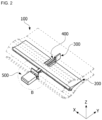
- FIG. 1 is a perspective view of an air vent for an automobile according to an embodiment
- FIG. 2 is a perspective view illustrating the remaining components except for a duct housing from the air vent for an automobile.
- an X direction may refer to a first direction, a vehicle width direction, or a left-right direction
- a Y direction may refer to a second direction
- a forward-backward direction or an air flow direction
- a Z direction may refer to a third direction or an up-down direction.
- the up-down direction may include an upward direction toward a ceiling of the automobile and a downward direction opposite to the upward direction.
- an air vent 1 for an automobile may include a duct housing 100, a first wing 200, a second wing 300, a link 400, and a handle unit 500.
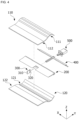
- FIG. 3 is an exploded perspective view of the air vent for an automobile according to an embodiment
- FIG. 4 is a rear-side exploded perspective view of the air vent for an automobile according to an embodiment
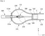
- FIG. 5 is a cross-sectional view taken along line A-A of FIG. 1 .
- the duct housing 100 may be connected to an air conditioner (not shown) and may guide air that is conditioned through the air conditioner (not shown) to the interior of the automobile.
- the duct housing 100 may include a first housing plate 110 and a second housing plate 120.
- the first housing plate 110 and the second housing plate 120 may be disposed to be spaced apart from each other.
- the first housing plate 110 may guide air that is supplied from the air conditioner (not shown).
- the first housing plate 110 may include a first flow path 111 and a second flow path 112.
- the first flow path 111 includes a Coanda surface that forms a Coanda effect, and the Coanda surface may guide the air to the interior of the automobile.
- the Coanda surface formed in the first flow path 111 may be a curved surface that is formed to be concave upward.
- the first flow path 111 may include a first fixing groove 111a formed on a side of an outlet 100a.
- the first fixing groove 111a may be disposed on an inner surface of the first flow path 111.
- the first fixing groove 111a may be formed to be concave upward.
- some components of the handle unit 500 may be coupled to the first fixing groove 111a. Accordingly, the first fixing groove 111a may support the handle unit 500.
- the second flow path 112 may be connected to the air conditioner (not shown).
- the second flow path 112 extends from an end portion of the first flow path 111 in the Y direction.
- the second flow path 112 may extend in a rectangular shape toward the air conditioner (not shown) from the end portion of the first flow path 111, but the present disclosure is not limited thereto.
- the second housing plate 120 may guide the air together with the first housing plate 110.
- the second housing plate 120 may include a third flow path 121 and a fourth flow path 122.
- the third flow path 121 may be formed in a shape symmetrical to the first flow path 111.
- the third flow path 121 includes a Coanda surface that forms a Coanda effect, and the Coanda surface may guide the air to the interior of the automobile.
- the Coanda surface formed in the third flow path 121 may be a curved surface that is formed to be concave downward.
- the third flow path 121 may be disposed to be spaced apart from the first flow path 111 in the Z direction. Accordingly, the outlet 100a may be formed between an end portion of the third flow path 121 and an end portion of the first flow path 111. In addition, the air may be discharged to the interior of the automobile through the outlet 100a.
- a width of the outlet 100a in the Z direction may be 20 mm or less.
- the handle unit 500 may be disposed in the outlet 100a.
- the third flow path 121 may include a second fixing groove 121a formed on a side of the outlet 100a.
- the second fixing groove 121a may be disposed on an inner surface of the third flow path 121.
- the second fixing groove 121a may be formed to be concave downward.
- some components of the handle unit 500 may be coupled to the second fixing groove 121a. Accordingly, the first fixing groove 111a and the second fixing groove 121a may support the handle unit 500.
- the fourth flow path 122 may be connected to the air conditioner (not shown).
- the fourth flow path 122 extends from an end portion of the third flow path 121 in the Y direction.
- the fourth flow path 122 may extend in a rectangular shape toward the air conditioner (not shown) from the end portion of the third flow path 121, but the present disclosure is not limited thereto.
- the fourth flow path 122 may be disposed to be spaced apart from the second flow path 112 in the Z direction. Accordingly, an inlet 100b through which the air supplied from the air conditioner (not shown) may be introduced may be formed at one side of the duct housing 100.
- the duct housing 100 may further include a third housing plate (not shown).
- the third housing plate (not shown) may cover a gap between an end portion of the first housing plate 110 in the X direction and an end portion of the second housing plate 120 in the X direction.
- FIG. 6 is a perspective view illustrating the first wing
- FIG. 7 is a view illustrating the first wing viewed from a rear side
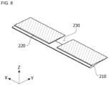
- FIG. 8 is a cross-sectional view taken along line C-C of FIG. 6
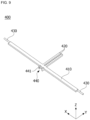
- FIG. 9 is a perspective view illustrating the link
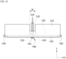
- FIG. 10 is a plan view illustrating a state in which the link is coupled to the first wing and the second wing
- FIG. 11 is a cross-sectional view illustrating the state in which the link is coupled to the first wing and the second wing.
- the first wing 200 may be disposed inside the duct housing 100.
- the first wing 200 may rotate in conjunction with the movement of the link 400 and the handle unit 500. Accordingly, a direction of air guided by the duct housing 100 may be controlled by the first wing 200 so that the air is discharged through the outlet 100a. For example, an upward or downward flow of air may be controlled by the first wing 200.
- the first wing 200 may include a first wing body 210, a link groove 220, and a link hole 230.
- the first wing body 210 is disposed between the first flow path 111 and the third flow path 121.
- the link 400 may be coupled to the first wing body 210.
- the first wing body 210 may control a flow direction of air moving along an inside of the duct housing 100 while rotating in conjunction with the movement of the link 400.
- the link groove 220 is formed on one side of the first wing body 210. As shown in FIG. 6 , the link groove 220 may be formed on a downstream side of the first wing body 210. At this point, the link groove 220 may be formed along the X direction. Accordingly, the link groove 220 may guide a left-right movement of the link 400. Here, the downstream may be distinguished from upstream on the basis of the flow of air, and may mean the outlet 100a side. Some components of the link 400 may be coupled to the link groove 220.
- the link hole 230 may be formed to pass through the first wing body 210.
- the link hole 230 may be disposed from a portion of the link groove 220 in a direction from the first flow path 111 toward the second flow path 112.
- the link hole 230 is formed to have a predetermined width to enable a left-right movement of a second link body 420. As shown in FIGS. 6 and 8 , the link hole 230 may be formed to communicate with one side of the link groove 220.
- the first wing 200 may further include a protruding rib 240.
- the protruding rib 240 may be formed to protrude from an end portion of the first wing 200 in the X direction.
- the protruding rib 240 may be in contact with the third housing plate (not shown) of the duct housing 100. Since the protruding rib 240 is disposed to be in contact with the third housing plate (not shown), the movement of the first wing 200 in the leftward or rightward direction may be prevented in advance even when the link 400 moves left and right. Accordingly, damage caused by direct contact of the first wing body 210 with the third housing plate (not shown) may be prevented.
- the second wing 300 may be disposed inside the duct housing 100.
- the second wing 300 may be disposed to be spaced apart from the first wing 200.
- the second wing 300 may be disposed upstream (a front side) than the first wing 200 on the basis of the flow direction of air.
- the second wing 300 may be disposed to intersect with the first wing 200 when viewed from the outlet 100a.
- the second wing 300 may include a second wing body 310 and a guide member 320.
- the second wing body 310 may be disposed between the second flow path 112 and the fourth flow path 122.
- the second wing body 310 may be formed in a plate shape.
- the guide member 320 may be disposed at an end portion of the second wing body 310.
- the guide member 320 is disposed in the Z direction and may be formed in a cylindrical shape.
- an end portion of the second link body 420 may be coupled to the guide member 320. Accordingly, the guide member 320 may guide an up-down movement of the second link body 420.
- the second wing 300 may be linked to the movement of the link 400 in the X direction, i.e., in the left-right direction. As shown in FIG. 5 , a rotation center C of the second wing 300 may be disposed in the front of the guide member 320. Accordingly, the second wing 300 may rotate about the rotation center C along a moving direction of the guide member 320.
- the second wing 300 may further include a hole 330 formed in the second wing body 310.
- the hole 330 may prevent rotational interference of the second link body 420 caused by the second wing body 310.
- the link 400 may include a first link body 410, the second link body 420, and a first rotating shaft 430.
- the link 400 may further include a coupling block 440 formed for coupling of the link 400 and the handle unit 500.
- the coupling block 440 may include coupling members 441 disposed in the X direction.
- the coupling members 441 may be coupled to some components of the handle unit 500.
- the coupling members 441 may be rotatably supported by some components of the handle unit 500.
- the handle unit 500 may be coupled to the link 400 to control the movement of the link 400.
- the rotating block 520 may include a second rotating shaft 521 and a rotating body 522 integrally formed to protrude from an outer circumferential surface of the second rotating shaft 521.
- the first knob body 531 may be coupled to the rotating body 522 to be slidably movable in the X direction.
- the first knob body 531 may include a block receiving groove 531a formed to receive the rotating block 520 therein.
- the block receiving groove 531a may receive a portion of the rotating body 522.
- the second knob body 532 may protrude from an end portion of the first knob body 531 toward the coupling member 441.
- the second knob body 532 may be disposed to be inclined toward the coupling member 441 from the end portion of the first knob body 531.
- An end portion of the second knob body 532 may be rotatably coupled to the coupling member 441.
- a first width W1 (in the X direction) of the block receiving groove 531a may be formed to be greater than a second width W2 (in the X direction) of the rotating body 522.
- the movement of the knob 530 may be guided by the rotating body 522 that is received in the block receiving groove 531a. That is, the knob 530 may move in the left-right direction by being guided by the rotating body 522. In addition, when the first knob body 531 slidably moves in the left-right direction, the first knob body 531 may be in contact with or released from the rotating body 522.
- the first knob body 531 when the first knob body 531 is slidably movable in one of the leftward or rightward direction by an operation of a user, a left inner surface or a right inner surface of the first knob body 531 comes into contact with one of a left side surface and a right side surface of the rotating body 522. In this state, when a pressing force is further transmitted to the first knob body 531, the first knob body 531 pushes the rotating body 522 in a sliding direction. Accordingly, the rotating body 522 may transmit the pressing force to the second knob body 532 and the link 400.
- the first knob body 531 may be slidably movable in a direction opposite to the direction, in which the first knob body 531 is slid, by an operation of the user in a state in which the first knob body 531 is in contact with the rotating body 522. Accordingly, the state in which the first knob body 531 is in contact with the rotating body 522 may be released.
- a rotation direction of the handle unit 500 may be opposite to a rotation direction of the link 400.
- the link 400 rotates about the first rotating shaft 430, and the knob 530 rotates about the second rotating shaft 521.
- the coupling member 441 is in a state of being supported by the second knob body 532.
- the coupling member 441 rotates in the same direction as the rotation direction of the second knob body 532 in conjunction with the rotation of the second knob body 532.
- the link 400 rotates in a direction different from the rotation direction of the second knob body 532 in conjunction with the rotation of the coupling member 441. Accordingly, the link 400 and the knob 530 rotate respectively about the first rotating shaft 430 and the second rotating shaft 521 in directions opposite to each other.
- the air may be discharged upward or downward in the interior of the automobile.
- the air vent 1 for an automobile may have a structure in which the movement of each of the first wing 200 and the second wing 300 is controlled by one link 400. Accordingly, in the air vent 1, through one link 400 disposed inside the first wing 200, the number of parts may be reduced and an internal structure of the air vent 1 may be simplified. Accordingly, through the above structure, manufacturing costs or assembly costs of the air vent 1 may be reduced.
- the air vent 1 for an automobile may discharge air to the lower side of the interior of the automobile through the movement of the knob 530.
- the first wing 200 and the link 400 are not rotated about the first rotating shaft 430 in a default state in which each of the components of the air vent 1 for an automobile is not moved upward or downward.
- the rotating block 520 and the knob 530 are disposed in a state of not being rotated about the second rotating shaft 521.
- Air passing through the inlet 100b is guided by the first wing 200 and moved upward toward the first flow path 111 by a Coanda effect.
- the air flows in a state of being in contact with the first flow path 111.
- the air is illustrated in FIG. 15B as being supplied to the lower side of the interior of the automobile through the air vent 1 for an automobile, the present disclosure is not limited thereto.
- the knob 530 may be rotated upward to discharge the air toward an upper side of the interior of the automobile.
- the air vent 1 for an automobile is maintained in the default state when there is no operation by the user.
- the default state all of the second wing 300, the second link body 420, and the knob 530 are disposed in a straight line.
- the first knob body 531 when the first knob body 531 is moved to the right side by an operation of the user from the default state, the first knob body 531 may be in contact with the rotating body 522 that is received in the block receiving groove 531a.
- the first knob body 531 when the user applies more pressure to the first knob body 531 while the first knob body 531 is in contact with the rotating body 522, the first knob body 531 further moves the rotating body 522 to the right side.
- the second knob body 532 transmits the pressing force to the coupling block 440 in conjunction with the movement of the first knob body 531.
- the first link body 410 moves inside the link groove 220 in the rightward direction.
- the second link body 420 protruding from the first link body 410 moves inside the link hole 230 in the rightward direction.
- the second wing 300 may be linked to the movement of the second link body 420. Accordingly, the second wing 300 rotates in the rightward direction (counterclockwise) using the rotation center C as a central axis.
- the air is illustrated in FIG. 16C as being supplied to the right side of the interior of the automobile through the air vent 1 for an automobile, the present disclosure is not limited thereto.
- the knob 530 may be moved in the leftward direction to discharge the air toward a left side of the interior of the automobile.
- the locking groove 250 is concavely formed on a portion of the first wing 200.
Landscapes
- Physics & Mathematics (AREA)
- Thermal Sciences (AREA)
- Engineering & Computer Science (AREA)
- Mechanical Engineering (AREA)
- Air-Flow Control Members (AREA)
- Air-Conditioning For Vehicles (AREA)
Abstract
Description
- This application claims priority to and the benefit of
Korean Patent Application No. 10-2021-0189847, filed on Dec 28, 2021 - The present disclosure relates to an air vent for an automobile.
- An automobile is equipped with an air conditioner for controlling interior air temperature and ventilation. The air conditioner generates warm air in the winter season to keep the interior of the automobile warm, and generates cold air in the summer season to keep the interior of the automobile cool.
- The air conditioner may include an air conditioning unit configured to control the temperature of air through heat exchange between the air and a heat exchange medium, and a blower unit configured to supply the air to the air conditioning unit. The automobile may provide the conditioned air to the interior of the automobile through an air vent connected to the air conditioning unit.
- A conventional air vent may include a front wing configured to control a leftward and rightward wind direction and a rear wing configured to control an upward and downward wind direction.
- However, in the conventional air vent, the rear wing may be disposed at a position close to an outlet through which air is discharged. Accordingly, since an operating radius of the rear wing according to upward and downward rotation of the rear wing and an operating radius of a structure configured to control the rotation of the rear wing should be secured, slimness of the outlet may not be achieved.
- Further, ease of operation of a knob is reduced due to a complicated structure for operating the structure.
- An embodiment provides an air vent for an automobile that is structurally improved so that an outlet is slimed down.
- Further, an embodiment provides an air vent for an automobile that is structurally improved so that ease of operation of a knob is improved.
- Further, an embodiment provides an air vent for an automobile that is structurally improved so that an operational structure thereof is simplified.
- One aspect of the present disclosure provides an air vent for an automobile including a duct housing configured to guide a flow of air and having an outlet formed therein, a first wing and a second wing disposed to be spaced apart from each other inside the duct housing, a link configured to control a rotation of each of the first wing and the second wing, and a handle unit coupled to the link and configured to control a movement of the link, in which the link is disposed to be movable and rotatable inside the first wing.
- When viewed from the outlet, the first wing and the second wing may be disposed to cross each other.
- The link may include a first link body disposed inside the first wing to be movable in a first direction that is a left-right direction, and a second link body extending toward the second wing from the first link body.
- The link may include a first rotating shaft formed to protrude from an end portion of the first direction side of the first link body, and the first link body may rotate about the first rotating shaft in conjunction with a rotation of the handle unit about the first direction.
- The second wing may include a second wing body and a guide member to which a one-side end portion of the second link body is coupled, and the one-side end portion of the second link body may be coupled to the guide member such that the second link body is slidably movable.
- The second wing may include a hole formed in the second wing body.
- The second wing may rotate in conjunction with a movement of the second link body in the first direction.
- The link may further include a coupling block integrally formed with the first link body, and a one-side end portion of the handle unit may be rotatably disposed in the coupling block.
- The first wing may rotate about the first rotating shaft in conjunction with the rotation of the first link body.
- The first wing may include a first wing body, a groove formed on one side of the first wing body, and a link hole formed to pass through the first wing body in a second direction that is a flow direction of the air, in which the first link body may be disposed in the groove, the second link body may be disposed in the link hole, and the link hole may be formed to have a predetermined width (W) in the first direction.
- The second link body may move in conjunction with a movement of the first link body in the first direction within a range of the width (W).
- The handle unit may include a fixed block coupled to the outlet of the duct housing, a rotating block rotatably coupled to the fixed block, and a knob coupled to the rotating block to be slidably movable in the first direction with respect to the rotating block, in which an end portion of the knob may be rotatably coupled to the coupling block.
- The knob may include a block receiving groove formed to receive the rotating block therein, and a width of the block receiving groove in the first direction may be greater than a width of the rotating block in the first direction.
- The duct housing may further include a fixing groove disposed on an inner surface thereof and formed on a side of the outlet, and the fixing groove may be coupled to the fixed block and support the fixed block.
- The link may further include a locking protrusion formed to protrude from the first link body, the first wing may further include a locking groove formed to correspond to the locking protrusion, and the locking protrusion may be coupled to the locking groove.
- When the knob is slidably movable, the knob may be in contact with or released from the rotating block.
- The first link body may be moved by a pressure applied in the first direction in a state in which the knob is in contact with the rotating block.
- The duct housing may include a Coanda surface disposed on an upper side and a lower side of the first wing.
- A rotation direction of the first wing and a rotation direction of the handle unit may be opposite to each other.
- The above and other objects, features and advantages of the present disclosure will become more apparent to those of ordinary skill in the art by describing in detail exemplary embodiments thereof with reference to the accompanying drawings, in which:
-
FIG. 1 is a perspective view of an air vent for an automobile according to an embodiment; -
FIG. 2 is a perspective view illustrating the remaining components except for a duct housing from an air vent for an automobile; -
FIG. 3 is an exploded perspective view of the air vent for an automobile according to an embodiment; -
FIG. 4 is a rear-side exploded perspective view of the air vent for an automobile according to an embodiment; -
FIG. 5 is a cross-sectional view taken along line A-A ofFIG. 1 ; -
FIG. 6 is a perspective view illustrating a first wing; -
FIG. 7 is a view illustrating the first wing viewed from a rear side; -
FIG. 8 is a cross-sectional view taken along line C-C ofFIG. 6 ; -
FIG. 9 is a perspective view illustrating a link; -
FIG. 10 is a plan view illustrating a state in which the link is coupled to the first wing and a second wing; -
FIG. 11 is a cross-sectional view illustrating the state in which the link is coupled to the first wing and the second wing; -
FIG. 12 is an exploded perspective view of a handle unit; -
FIG. 13 is a view illustrating a state in which a knob is coupled to a rotating block in a plane view; -
FIG. 14 is an enlarged view of portion B ofFIG. 2 ; -
FIG. 15A is a cross-sectional view illustrating a default state of the air vent for an automobile; -
FIG. 15B is a cross-sectional view illustrating a state in which the first wing, the link, and the handle unit are rotated; -
FIG. 16A is a plan view illustrating the default state of the air vent for an automobile; -
FIG. 16B is a plan view illustrating a state in which a first knob body is in contact with a rotating body; -
FIG. 16C is a plan view illustrating a state in which the second wing is rotated; -
FIG. 17A is a view illustrating a locking groove; -
FIG. 17B is a view illustrating a locking protrusion; and -
FIG. 18 is a view illustrating a state in which the locking protrusion is coupled to the locking groove. - The present disclosure may be modified in various forms and have various embodiments, and thus particular embodiments thereof will be illustrated in the accompanying drawings and described in the detailed description. However, it should be understood that there is no intention to limit the present disclosure to the particular embodiments disclosed, and, on the contrary, the present disclosure is to cover all modifications, equivalents, and alternatives falling within the spirit and scope of the present disclosure.
- It should be understood that, although the terms including ordinal numbers such as first, second, and the like may be used herein to describe various elements, the elements are not limited by the terms. The terms are used only for the purpose of distinguishing one component from another component. For example, without departing from the scope of the present disclosure, a second component may be referred to as a first component, and similarly, a first component may also be referred to as a second component. The term "and/or" includes a combination of a plurality of related listed items or any one item of the plurality of related listed items.
- When a component is referred to as being "connected" or "coupled" to another component, it may be directly connected or coupled to another component, but it should be understood that still another component may be present between the component and another component. In contrast, when a component is referred to as being "directly connected," or "directly coupled" to another component, it should be understood that still another component may not be present between the component and another component.
- In descriptions of the embodiment, when one component is referred to as being formed "on or under" another component, two components may be in direct contact with each other or at least one still another component may be indirectly formed between the two components. Further, the term "on or under" may refer to not only an upward direction but also a downward direction based on one component.
- The terms used herein are for the purpose of describing particular embodiments only and are not intended to be limiting to the present disclosure. As used herein, singular forms are intended to include plural forms as well, unless the context clearly indicates otherwise. In the present application, it should be understood that the terms "comprise," "comprising," "include," and/or "including", when used in this specification, specify the presence of stated features, integers, steps, operations, elements, components and/or groups thereof but do not preclude the presence or addition of one or more other features, integers, steps, operations, elements, components and/or groups thereof.
- Terms, such as those defined in commonly used dictionaries, should be interpreted as having a meaning that is consistent with their meaning in the context of the relevant art and will not be interpreted in an idealized or overly formal sense unless clearly defined in the present application. It should be understood that terms, such as those defined in commonly used dictionaries, should be interpreted as having a meaning that is consistent with their meaning in the context of the relevant art and are not to be interpreted in an idealized or overly formal sense unless expressly so defined herein.
- Hereinafter, embodiments of the present disclosure will be described in detail with reference to the accompanying drawings. Regardless of reference numerals, like numbers refer to like elements throughout the description of the figures, and the description of the same elements will be not reiterated.
- An air vent for an automobile according to an embodiment is connected to an air conditioner (not shown) of an automobile and may control an air direction of conditioned air to supply the conditioned air to an interior of the automobile.
-
FIG. 1 is a perspective view of an air vent for an automobile according to an embodiment, andFIG. 2 is a perspective view illustrating the remaining components except for a duct housing from the air vent for an automobile. - In
FIGS. 1 and2 , an X direction may refer to a first direction, a vehicle width direction, or a left-right direction, a Y direction may refer to a second direction, a forward-backward direction, or an air flow direction, and a Z direction may refer to a third direction or an up-down direction. In addition, the up-down direction may include an upward direction toward a ceiling of the automobile and a downward direction opposite to the upward direction. - Referring to
FIGS. 1 and2 , anair vent 1 for an automobile may include aduct housing 100, afirst wing 200, asecond wing 300, alink 400, and ahandle unit 500. -
FIG. 3 is an exploded perspective view of the air vent for an automobile according to an embodiment,FIG. 4 is a rear-side exploded perspective view of the air vent for an automobile according to an embodiment, andFIG. 5 is a cross-sectional view taken along line A-A ofFIG. 1 . - Referring to
FIGS. 1 and3 to 5 , theduct housing 100 may be connected to an air conditioner (not shown) and may guide air that is conditioned through the air conditioner (not shown) to the interior of the automobile. - The
duct housing 100 may include afirst housing plate 110 and asecond housing plate 120. - The
first housing plate 110 and thesecond housing plate 120 may be disposed to be spaced apart from each other. - The
first housing plate 110 may guide air that is supplied from the air conditioner (not shown). - The
first housing plate 110 may include afirst flow path 111 and asecond flow path 112. - The
first flow path 111 includes a Coanda surface that forms a Coanda effect, and the Coanda surface may guide the air to the interior of the automobile. Here, the Coanda surface formed in thefirst flow path 111 may be a curved surface that is formed to be concave upward. - The
first flow path 111 may include afirst fixing groove 111a formed on a side of anoutlet 100a. Thefirst fixing groove 111a may be disposed on an inner surface of thefirst flow path 111. Thefirst fixing groove 111a may be formed to be concave upward. In addition, some components of thehandle unit 500 may be coupled to thefirst fixing groove 111a. Accordingly, thefirst fixing groove 111a may support thehandle unit 500. - The
second flow path 112 may be connected to the air conditioner (not shown). Thesecond flow path 112 extends from an end portion of thefirst flow path 111 in the Y direction. Thesecond flow path 112 may extend in a rectangular shape toward the air conditioner (not shown) from the end portion of thefirst flow path 111, but the present disclosure is not limited thereto. - The
second housing plate 120 may guide the air together with thefirst housing plate 110. - The
second housing plate 120 may include athird flow path 121 and afourth flow path 122. - The
third flow path 121 may be formed in a shape symmetrical to thefirst flow path 111. Thethird flow path 121 includes a Coanda surface that forms a Coanda effect, and the Coanda surface may guide the air to the interior of the automobile. Here, the Coanda surface formed in thethird flow path 121 may be a curved surface that is formed to be concave downward. - The
third flow path 121 may be disposed to be spaced apart from thefirst flow path 111 in the Z direction. Accordingly, theoutlet 100a may be formed between an end portion of thethird flow path 121 and an end portion of thefirst flow path 111. In addition, the air may be discharged to the interior of the automobile through theoutlet 100a. Here, a width of theoutlet 100a in the Z direction may be 20 mm or less. - Further, the
handle unit 500 may be disposed in theoutlet 100a. - The
third flow path 121 may include asecond fixing groove 121a formed on a side of theoutlet 100a. Thesecond fixing groove 121a may be disposed on an inner surface of thethird flow path 121. Thesecond fixing groove 121a may be formed to be concave downward. In addition, some components of thehandle unit 500 may be coupled to thesecond fixing groove 121a. Accordingly, thefirst fixing groove 111a and thesecond fixing groove 121a may support thehandle unit 500. - The
fourth flow path 122 may be connected to the air conditioner (not shown). Thefourth flow path 122 extends from an end portion of thethird flow path 121 in the Y direction. Thefourth flow path 122 may extend in a rectangular shape toward the air conditioner (not shown) from the end portion of thethird flow path 121, but the present disclosure is not limited thereto. - The
fourth flow path 122 may be disposed to be spaced apart from thesecond flow path 112 in the Z direction. Accordingly, aninlet 100b through which the air supplied from the air conditioner (not shown) may be introduced may be formed at one side of theduct housing 100. - The
duct housing 100 may further include a third housing plate (not shown). The third housing plate (not shown) may cover a gap between an end portion of thefirst housing plate 110 in the X direction and an end portion of thesecond housing plate 120 in the X direction. -
FIG. 6 is a perspective view illustrating the first wing,FIG. 7 is a view illustrating the first wing viewed from a rear side,FIG. 8 is a cross-sectional view taken along line C-C ofFIG. 6 ,FIG. 9 is a perspective view illustrating the link,FIG. 10 is a plan view illustrating a state in which the link is coupled to the first wing and the second wing, andFIG. 11 is a cross-sectional view illustrating the state in which the link is coupled to the first wing and the second wing. - Referring to
FIGS. 5 to 8 , thefirst wing 200 may be disposed inside theduct housing 100. - The
first wing 200 may rotate in conjunction with the movement of thelink 400 and thehandle unit 500. Accordingly, a direction of air guided by theduct housing 100 may be controlled by thefirst wing 200 so that the air is discharged through theoutlet 100a. For example, an upward or downward flow of air may be controlled by thefirst wing 200. - The
first wing 200 may include afirst wing body 210, alink groove 220, and alink hole 230. - The
first wing body 210 is disposed between thefirst flow path 111 and thethird flow path 121. Thelink 400 may be coupled to thefirst wing body 210. Thefirst wing body 210 may control a flow direction of air moving along an inside of theduct housing 100 while rotating in conjunction with the movement of thelink 400. - The
link groove 220 is formed on one side of thefirst wing body 210. As shown inFIG. 6 , thelink groove 220 may be formed on a downstream side of thefirst wing body 210. At this point, thelink groove 220 may be formed along the X direction. Accordingly, thelink groove 220 may guide a left-right movement of thelink 400. Here, the downstream may be distinguished from upstream on the basis of the flow of air, and may mean theoutlet 100a side. Some components of thelink 400 may be coupled to thelink groove 220. - The
link hole 230 may be formed to pass through thefirst wing body 210. - The
link hole 230 may be disposed from a portion of thelink groove 220 in a direction from thefirst flow path 111 toward thesecond flow path 112. - As shown in
FIG. 10 , thelink hole 230 is formed to have a predetermined width to enable a left-right movement of asecond link body 420. As shown inFIGS. 6 and8 , thelink hole 230 may be formed to communicate with one side of thelink groove 220. - As shown in
FIGS. 6 and7 , thefirst wing 200 may further include aprotruding rib 240. - The protruding
rib 240 may be formed to protrude from an end portion of thefirst wing 200 in the X direction. The protrudingrib 240 may be in contact with the third housing plate (not shown) of theduct housing 100. Since the protrudingrib 240 is disposed to be in contact with the third housing plate (not shown), the movement of thefirst wing 200 in the leftward or rightward direction may be prevented in advance even when thelink 400 moves left and right. Accordingly, damage caused by direct contact of thefirst wing body 210 with the third housing plate (not shown) may be prevented. - Referring to
FIGS. 2 ,3 , and5 , thesecond wing 300 may be disposed inside theduct housing 100. Thesecond wing 300 may be disposed to be spaced apart from thefirst wing 200. Specifically, thesecond wing 300 may be disposed upstream (a front side) than thefirst wing 200 on the basis of the flow direction of air. Thesecond wing 300 may be disposed to intersect with thefirst wing 200 when viewed from theoutlet 100a. - The
second wing 300 may include asecond wing body 310 and aguide member 320. - The
second wing body 310 may be disposed between thesecond flow path 112 and thefourth flow path 122. Thesecond wing body 310 may be formed in a plate shape. - The
guide member 320 may be disposed at an end portion of thesecond wing body 310. Theguide member 320 is disposed in the Z direction and may be formed in a cylindrical shape. As shown inFIG. 11 , an end portion of thesecond link body 420 may be coupled to theguide member 320. Accordingly, theguide member 320 may guide an up-down movement of thesecond link body 420. - The
second wing 300 may be linked to the movement of thelink 400 in the X direction, i.e., in the left-right direction. As shown inFIG. 5 , a rotation center C of thesecond wing 300 may be disposed in the front of theguide member 320. Accordingly, thesecond wing 300 may rotate about the rotation center C along a moving direction of theguide member 320. - Meanwhile, the
second wing 300 may further include ahole 330 formed in thesecond wing body 310. - When the
second wing 300 rotates according to the left-right movement of thesecond link body 420, thehole 330 may prevent rotational interference of thesecond link body 420 caused by thesecond wing body 310. - Referring to
FIGS. 2 and9 to 11 , thelink 400 may transmit the movement of thehandle unit 500 to at least one of thefirst wing 200 and thesecond wing 300. Thelink 400 may be coupled to thefirst wing 200 and thesecond wing 300. In addition, one side of thelink 400 may be coupled to thehandle unit 500. Accordingly, the movement of thelink 400 may be controlled by thehandle unit 500. - The
link 400 may include afirst link body 410, thesecond link body 420, and a firstrotating shaft 430. In addition, thelink 400 may further include acoupling block 440 formed for coupling of thelink 400 and thehandle unit 500. - As shown in
FIG. 10 , thefirst link body 410 may be coupled to thelink groove 220. Here, thefirst link body 410 may be disposed in thelink groove 220 to be movable in the X direction, which is the left-right direction. - The
second link body 420 may extend toward thesecond wing 300 from one side of thefirst link body 410. As shown inFIG. 10 , thesecond link body 420 may be disposed inside thelink hole 230. Thesecond link body 420 may be provided as two second link body members that are disposed to be spaced apart from each other in the X direction. Here, the second link body member may be formed in a bar shape. The end portion of thesecond link body 420 may be coupled to theguide member 320 to be slidably movable in the Z direction. For example, since theguide member 320 may be disposed between the second link body members, thesecond link body 420 may move in the Z direction. - The first
rotating shaft 430 may protrude from an end portion of thefirst link body 410 in the X direction. The firstrotating shaft 430 may be rotatably coupled to the third housing plate (not shown). - A rotation center of the first
rotating shaft 430 and a rotation center of thefirst wing body 210 may be equal to each other. Accordingly, thefirst wing 200 may rotate about the firstrotating shaft 430 together with thefirst link body 410 in conjunction with the movement of thehandle unit 500 in the up-down direction. - The
coupling block 440 may be integrally formed with thefirst link body 410. Thecoupling block 440 may be disposed in the rear of thefirst link body 410. Thecoupling block 440 may be disposed to be exposed to the outside of thefirst wing 200. Thecoupling block 440 may be coupled to thehandle unit 500. - The
coupling block 440 may include couplingmembers 441 disposed in the X direction. Thecoupling members 441 may be coupled to some components of thehandle unit 500. Thecoupling members 441 may be rotatably supported by some components of thehandle unit 500. -
FIG. 12 is an exploded perspective view of the handle unit,FIG. 13 is a view illustrating a state in which a knob is coupled to a rotating block in a plan view, andFIG. 14 is an enlarged view of portion B ofFIG. 2 . - Referring to
FIGS. 1 ,2 , and12 to 14 , thehandle unit 500 may be coupled to thelink 400 to control the movement of thelink 400. - The
handle unit 500 may include afixed block 510, arotating block 520, and aknob 530. - The fixed
block 510 may be disposed on theoutlet 100a of theduct housing 100. Specifically, the fixedblock 510 may be coupled and fixed to thefirst fixing groove 111a of thefirst housing plate 110 and thesecond fixing groove 121a of thesecond housing plate 120. The fixedblock 510 may include a hole formed such that therotating block 520 may be disposed therein. Since the fixedblock 510 supports thefirst housing plate 110 and thesecond housing plate 120, thefirst housing plate 110 and thesecond housing plate 120 may be maintained in a state of being spaced apart from each other. - The
rotating block 520 may be rotatably coupled to the fixedblock 510. - The
rotating block 520 may include a secondrotating shaft 521 and arotating body 522 integrally formed to protrude from an outer circumferential surface of the secondrotating shaft 521. - The second
rotating shaft 521 may be rotatably coupled to the fixedblock 510. The secondrotating shaft 521 may rotatably support therotating body 522 that is linked to the movement of theknob 530 in the up-down direction. - The
rotating body 522 may be formed in a plate shape. Therotating body 522 may rotate in conjunction with the movement of theknob 530 in the up-down direction. For example, since a portion of therotating body 522 is disposed inside theknob 530, therotating body 522 may rotate in conjunction with the rotation of theknob 530. - Further, the
rotating body 522 may guide theknob 530 to be slidably movable in the left-right direction. - The
knob 530 may be coupled to therotating body 522. Theknob 530 may include afirst knob body 531 and asecond knob body 532. - The
first knob body 531 may be coupled to therotating body 522 to be slidably movable in the X direction. - The
first knob body 531 may include ablock receiving groove 531a formed to receive therotating block 520 therein. Theblock receiving groove 531a may receive a portion of therotating body 522. - The
second knob body 532 may protrude from an end portion of thefirst knob body 531 toward thecoupling member 441. Thesecond knob body 532 may be disposed to be inclined toward thecoupling member 441 from the end portion of thefirst knob body 531. An end portion of thesecond knob body 532 may be rotatably coupled to thecoupling member 441. - As shown in
FIG. 13 , a first width W1 (in the X direction) of theblock receiving groove 531a may be formed to be greater than a second width W2 (in the X direction) of therotating body 522. - In addition, the movement of the
knob 530 may be guided by therotating body 522 that is received in theblock receiving groove 531a. That is, theknob 530 may move in the left-right direction by being guided by therotating body 522. In addition, when thefirst knob body 531 slidably moves in the left-right direction, thefirst knob body 531 may be in contact with or released from therotating body 522. - For example, when the
first knob body 531 is slidably movable in one of the leftward or rightward direction by an operation of a user, a left inner surface or a right inner surface of thefirst knob body 531 comes into contact with one of a left side surface and a right side surface of therotating body 522. In this state, when a pressing force is further transmitted to thefirst knob body 531, thefirst knob body 531 pushes therotating body 522 in a sliding direction. Accordingly, therotating body 522 may transmit the pressing force to thesecond knob body 532 and thelink 400. - Further, the
first knob body 531 may be slidably movable in a direction opposite to the direction, in which thefirst knob body 531 is slid, by an operation of the user in a state in which thefirst knob body 531 is in contact with therotating body 522. Accordingly, the state in which thefirst knob body 531 is in contact with therotating body 522 may be released. - A rotation direction of the
handle unit 500 may be opposite to a rotation direction of thelink 400. - For example, the
link 400 rotates about the firstrotating shaft 430, and theknob 530 rotates about the secondrotating shaft 521. Here, thecoupling member 441 is in a state of being supported by thesecond knob body 532. In addition, thecoupling member 441 rotates in the same direction as the rotation direction of thesecond knob body 532 in conjunction with the rotation of thesecond knob body 532. In addition, thelink 400 rotates in a direction different from the rotation direction of thesecond knob body 532 in conjunction with the rotation of thecoupling member 441. Accordingly, thelink 400 and theknob 530 rotate respectively about the firstrotating shaft 430 and the secondrotating shaft 521 in directions opposite to each other. - Accordingly, when the
first wing 200 is rotated by an operation of thehandle unit 500, the air may be discharged upward or downward in the interior of the automobile. - In the
air vent 1 for an automobile according to an embodiment, thefirst wing 200 may be disposed between thefirst flow path 111 and thethird flow path 121. Accordingly, a restriction in a rotation radius of thefirst wing 200 may be eliminated. - In addition, since the
air vent 1 for an automobile uses thelink 400, the necessity of disposing thefirst wing 200 close to theoutlet 100a may be reduced. - Furthermore, a position at which the Coanda surface is formed may be controlled through the
link 400. - Accordingly, in the
air vent 1 for an automobile, the width of theoutlet 100a may be reduced and a degree of design freedom of a dashboard of the automobile may be improved. - Further, the
air vent 1 for an automobile according to an embodiment may have a structure in which the movement of each of thefirst wing 200 and thesecond wing 300 is controlled by onelink 400. Accordingly, in theair vent 1, through onelink 400 disposed inside thefirst wing 200, the number of parts may be reduced and an internal structure of theair vent 1 may be simplified. Accordingly, through the above structure, manufacturing costs or assembly costs of theair vent 1 may be reduced. - Hereinafter, a process of supplying the air transmitted from the air conditioner (not shown) to a lower side of the interior of the automobile through the air vent for an automobile will be described.
-
FIG. 15A is a cross-sectional view illustrating a default state of the air vent for an automobile, andFIG. 15B is a cross-sectional view illustrating a state in which the first wing, the link, and the handle unit are rotated. - Referring to
FIGS. 15A and15B , theair vent 1 for an automobile may discharge air to the lower side of the interior of the automobile through the movement of theknob 530. - As shown in
FIG. 15A , thefirst wing 200 and thelink 400 are not rotated about the firstrotating shaft 430 in a default state in which each of the components of theair vent 1 for an automobile is not moved upward or downward. In addition, in the default state, therotating block 520 and theknob 530 are disposed in a state of not being rotated about the secondrotating shaft 521. - As shown in
FIG. 15B , when thefirst knob body 531 is rotated downward by an operation of the user, thesecond knob body 532 rotates upward about the secondrotating shaft 521. At the same time, thecoupling member 441 coupled to thesecond knob body 532 is linked to the movement of thesecond knob body 532 and rotated upward about the firstrotating shaft 430. - In this process, the
first wing 200 and thefirst link body 410 rotate about the firstrotating shaft 430, and the end portion of thesecond link body 420 is disposed moved by sliding below theguide member 320. - Accordingly, the
first wing 200 is disposed to be inclined downward with respect to a direction toward theinlet 100b from theoutlet 100a. - Air passing through the
inlet 100b is guided by thefirst wing 200 and moved upward toward thefirst flow path 111 by a Coanda effect. The air flows in a state of being in contact with thefirst flow path 111. - The air guided by the
first wing 200 and thefirst flow path 111 may be discharged toward the lower side of the interior of the automobile by passing through theoutlet 100a. - Although the air is illustrated in
FIG. 15B as being supplied to the lower side of the interior of the automobile through theair vent 1 for an automobile, the present disclosure is not limited thereto. For example, theknob 530 may be rotated upward to discharge the air toward an upper side of the interior of the automobile. - Hereinafter, a process of supplying the air transmitted from the air conditioner (not shown) to a right side of the interior of the automobile will be described.
-
FIG. 16A is a plan view illustrating the default state of the air vent for an automobile,FIG. 16B is a plan view illustrating a state in which the first knob body is in contact with the rotating body, andFIG. 16C is a plan view illustrating a state in which the second wing is rotated. - Referring to
FIGS. 16A to 16C , theair vent 1 for an automobile may supply conditioned air to the right side of the interior of the automobile through the movement of theknob 530 in the left-right direction. - As shown in
FIG. 16A , theair vent 1 for an automobile is maintained in the default state when there is no operation by the user. In the default state, all of thesecond wing 300, thesecond link body 420, and theknob 530 are disposed in a straight line. - As shown in
FIG. 16B , when thefirst knob body 531 is moved to the right side by an operation of the user from the default state, thefirst knob body 531 may be in contact with therotating body 522 that is received in theblock receiving groove 531a. - As shown in
FIG. 16C , when the user applies more pressure to thefirst knob body 531 while thefirst knob body 531 is in contact with therotating body 522, thefirst knob body 531 further moves therotating body 522 to the right side. - The
second knob body 532 transmits the pressing force to thecoupling block 440 in conjunction with the movement of thefirst knob body 531. - When the pressing force is transmitted to the
coupling block 440, thefirst link body 410 moves inside thelink groove 220 in the rightward direction. In addition, thesecond link body 420 protruding from thefirst link body 410 moves inside thelink hole 230 in the rightward direction. - Since the end portion of the
second link body 420 is in a state of being coupled to theguide member 320, thesecond wing 300 may be linked to the movement of thesecond link body 420. Accordingly, thesecond wing 300 rotates in the rightward direction (counterclockwise) using the rotation center C as a central axis. - Referring to
FIG. 16C , air flowing into theinlet 100b is guided in the rightward direction by thesecond wing 300. Accordingly, the air may be supplied in the rightward direction of the interior of the automobile through theoutlet 100a. - Although the air is illustrated in
FIG. 16C as being supplied to the right side of the interior of the automobile through theair vent 1 for an automobile, the present disclosure is not limited thereto. For example, theknob 530 may be moved in the leftward direction to discharge the air toward a left side of the interior of the automobile. -
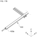
FIG. 17A is a view illustrating a locking groove, andFIG. 17B is a view illustrating a locking protrusion. - Referring to
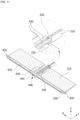
FIGS. 17A ,17B , and18 , theair vent 1 for an automobile may further include a lockingprotrusion 410a formed on thefirst link body 410 and a lockinggroove 250 formed on thefirst wing 200. - As shown in
FIGS. 17A and18 , the lockinggroove 250 is concavely formed on a portion of thefirst wing 200. - As shown in
FIGS. 17B and18 , the lockingprotrusion 410a may protrude from an outer surface of thefirst link body 410 to correspond to the lockinggroove 250. The lockingprotrusion 410a may be coupled to the lockinggroove 250. The coupling of the lockingprotrusion 410a and the lockinggroove 250 may prevent thefirst link body 410 from being separated. Thefirst link body 410 may be stably maintained in a state in which thefirst link body 410 is disposed inside thefirst wing 200 by the coupling of the lockinggroove 250 and the lockingprotrusion 410a. - According to an embodiment, it is possible to achieve slimness of an outlet through a link disposed inside a first wing. Accordingly, according to the embodiment, it is possible to improve a degree of design freedom of an automobile dashboard disposed in an interior of an automobile.
- Further, according to the embodiment, a user can easily control a wind direction by implementing a coupling structure of a knob and a link that allows an operation of the knob to be simplified.
- Further, according to the embodiment, it is possible to simplify an operation structure through the coupling structure, so that manufacturing costs or assembly costs of the product can be reduced.
- Various and advantageous advantages and effects of the embodiments are not limited to the above descriptions and will be more easily understood in a process of describing specific embodiments of the present disclosure.
- The present disclosure has been described above with reference to the embodiment of the present disclosure, but it should be understood by those skilled in the art that various changes and modifications may be made therein without departing from the spirit and scope of the present disclosure defined by the appended claims. Further, differences related to modifications and changes should be understood to be included in the scope of the present disclosure defined in the appended claims.
Claims (19)
- An air vent for an automobile, the air vent comprising:a duct housing (100) configured to guide a flow of air and having an outlet (100a) formed therein;a first wing (200) and a second wing (300) disposed to be spaced apart from each other inside the duct housing (100);a link (400) configured to control a rotation of each of the first wing (200) and the second wing (300); anda handle unit (500) coupled to the link (400) and configured to control a movement of the link (400),wherein the link (400) is disposed to be movable and rotatable inside the first wing (200).
- The air vent of claim 1, wherein when viewed from the outlet (100a), the first wing (200) and the second wing (300) are disposed to cross each other.
- The air vent of claim 1, wherein
the link (400) includes:a first link body (410) disposed inside the first wing (200) and disposed to be movable in a first direction that is a left-right direction; anda second link body (420) extending toward the second wing (300) from the first link body (410). - The air vent of claim 3, whereinthe link (400) further includes a first rotating shaft (430) protruding from an end portion of the first link body (410) in the first direction, andthe first link body (410) rotates about the first rotating shaft (430) in conjunction with a rotation of the handle unit (500) about the first direction.
- The air vent of claim 3, whereinthe second wing (300) includes a second wing body (310) and a guide member (320) to which a one-side end portion of the second link body (420) is coupled, andthe one-side end portion of the second link body (420) is coupled to the guide member (320) such that the second link body (420) is slidably movable.
- The air vent of claim 5, wherein the second wing (300) includes a hole defined in the second wing body (310).
- The air vent of claim 5, wherein the second wing (300) rotates in conjunction with a movement of the second link body (420) in the first direction.
- The air vent of claim 4, whereinthe link (400) further includes a coupling block (440) integrally formed with the first link body (410), anda one-side end portion of the handle unit (500) is rotatably disposed in the coupling block (440).
- The air vent of claim 4, wherein the first wing (200) rotates about the first rotating shaft (430) in conjunction with a rotation of the first link body (410).
- The air vent of claim 3, wherein
the first wing (200) includes:a first wing body (210);a groove (220) defined on one side of the first wing body (210); anda link hole (230) passing through the first wing body (210) in a second direction that is a flow direction of the air,wherein the first link body (410) is disposed in the groove (220),the second link body (420) is disposed in the link hole (230), andthe link hole (230) has a predetermined width (W) in the first direction. - The air vent of claim 10, wherein
the second link body (420) moves in conjunction with a movement of the first link body (410) in the first direction within a range of the predetermined width (W). - The air vent of claim 8, wherein
the handle unit (500) includes:a fixed block (510) coupled to the outlet (100a) of the duct housing (100);a rotating block (520) rotatably coupled to the fixed block (510); anda knob (530) coupled to the rotating block (520) and disposed to be slidably movable in the first direction with respect to the rotating block (520),wherein an end portion of the knob (530) is rotatably coupled to the coupling block (440). - The air vent of claim 12, whereinthe knob (530) includes a block receiving groove (531) formed to receive the rotating block (520) therein,wherein a width of the block receiving groove (531) in the first direction is greater than a width of the rotating block (520) in the first direction.
- The air vent of claim 12, whereinthe duct housing (100) further includes a fixing groove (111a, 121a) disposed on an inner surface thereof and extending on a side of the outlet (100a),wherein the fixing groove (111a, 121a) is coupled to the fixed block (510) and supports the fixed block (510).
- The air vent of claim 3, whereinthe link (400) further includes a locking protrusion (410a) protruding from the first link body (410),the first wing (200) further includes a locking groove (250) disposed to receive the locking protrusion (410a) therein, andthe locking protrusion (410a) is coupled to the locking groove (250).
- The air vent of claim 13, wherein when the knob (530) is slidably movable, the knob (530) is in contact with or released from the rotating block (520).
- The air vent of claim 16, wherein the first link body (410) is movable by a pressure applied in the first direction in a state in which the knob (530) is in contact with the rotating block (520).
- The air vent of claim 1, wherein the duct housing (100) includes a Coanda surface disposed on an upper side and a lower side of the first wing (200).
- The air vent of claim 1, wherein a rotation direction of the first wing (200) and a rotation direction of the handle unit (500) are opposite to each other.
Applications Claiming Priority (1)
| Application Number | Priority Date | Filing Date | Title |
|---|---|---|---|
| KR1020210189847A KR102658320B1 (en) | 2021-12-28 | 2021-12-28 | Air vent for automobile |
Publications (2)
| Publication Number | Publication Date |
|---|---|
| EP4206009A1 true EP4206009A1 (en) | 2023-07-05 |
| EP4206009B1 EP4206009B1 (en) | 2025-02-19 |
Family
ID=80780829
Family Applications (1)
| Application Number | Title | Priority Date | Filing Date |
|---|---|---|---|
| EP22162130.3A Active EP4206009B1 (en) | 2021-12-28 | 2022-03-15 | Air vent for an automobile |
Country Status (4)
| Country | Link |
|---|---|
| US (1) | US12083867B2 (en) |
| EP (1) | EP4206009B1 (en) |
| KR (1) | KR102658320B1 (en) |
| CN (1) | CN116353300A (en) |
Citations (3)
| Publication number | Priority date | Publication date | Assignee | Title |
|---|---|---|---|---|
| JP2009018634A (en) * | 2007-07-10 | 2009-01-29 | Howa Kasei Kk | Air blowout adjustment register |
| US20120291893A1 (en) * | 2010-01-22 | 2012-11-22 | Kabushiki Kaisha Toyota Jidoshokki | Register |
| KR102162869B1 (en) * | 2019-05-08 | 2020-10-07 | 주식회사 니프코코리아 | Air vent for vehicle |
Family Cites Families (8)
| Publication number | Priority date | Publication date | Assignee | Title |
|---|---|---|---|---|
| DE10057421B4 (en) * | 2000-11-20 | 2006-01-12 | Trw Automotive Electronics & Components Gmbh & Co. Kg | Air outlet for ventilation systems |
| JP6077375B2 (en) * | 2013-04-18 | 2017-02-08 | 豊和化成株式会社 | Register operation knob |
| JP6100202B2 (en) * | 2014-05-14 | 2017-03-22 | 豊田合成株式会社 | Air conditioning register |
| SE538880C2 (en) * | 2014-11-10 | 2017-01-24 | China-Euro Vehicle Tech Ab | Air nozzle device for a vehicle |
| JP6579002B2 (en) * | 2016-03-10 | 2019-09-25 | 豊田合成株式会社 | Air conditioning register |
| JP7013149B2 (en) * | 2017-06-30 | 2022-01-31 | 豊和化成株式会社 | register |
| US10807443B2 (en) * | 2017-10-31 | 2020-10-20 | Honda Motor Co., Ltd. | Air vent for a vehicle HVAC system |
| KR102110320B1 (en) * | 2019-03-29 | 2020-05-14 | 주식회사 니프코코리아 | air vent for car |
-
2021
- 2021-12-28 KR KR1020210189847A patent/KR102658320B1/en active Active
-
2022
- 2022-03-15 EP EP22162130.3A patent/EP4206009B1/en active Active
- 2022-03-17 US US17/697,159 patent/US12083867B2/en active Active
- 2022-08-30 CN CN202211046892.XA patent/CN116353300A/en active Pending
Patent Citations (3)
| Publication number | Priority date | Publication date | Assignee | Title |
|---|---|---|---|---|
| JP2009018634A (en) * | 2007-07-10 | 2009-01-29 | Howa Kasei Kk | Air blowout adjustment register |
| US20120291893A1 (en) * | 2010-01-22 | 2012-11-22 | Kabushiki Kaisha Toyota Jidoshokki | Register |
| KR102162869B1 (en) * | 2019-05-08 | 2020-10-07 | 주식회사 니프코코리아 | Air vent for vehicle |
Also Published As
| Publication number | Publication date |
|---|---|
| KR20230100166A (en) | 2023-07-05 |
| US20230202264A1 (en) | 2023-06-29 |
| KR102658320B1 (en) | 2024-04-18 |
| US12083867B2 (en) | 2024-09-10 |
| EP4206009B1 (en) | 2025-02-19 |
| CN116353300A (en) | 2023-06-30 |
Similar Documents
| Publication | Publication Date | Title |
|---|---|---|
| US6840852B2 (en) | Air duct outlets with manual and automatic air stream direction control | |
| US10675938B2 (en) | Air conditioner for vehicle and controlling method thereof | |
| US4802405A (en) | Automotive air-conditioner | |
| US5036753A (en) | Dual mode air outlet for air conditioning system | |
| US6743090B2 (en) | Vehicle air conditioner with rotary door | |
| EP0691228B1 (en) | Air passage switching system and vehicular air conditioning system | |
| AU752056B2 (en) | Air mix damper device and vehicle air conditioner | |
| US12179553B2 (en) | Vehicle air vent with knob for controlling a first wing, second wing and guide case | |
| EP4206009B1 (en) | Air vent for an automobile | |
| CN109945304B (en) | Air Conditioner | |
| JP2000108639A (en) | Door drive mechanism of vehicle air conditioner | |
| CN109945308B (en) | Air Conditioner | |
| EP3578397A1 (en) | Air conditionning system for vehicle | |
| KR102789710B1 (en) | Air conditioner for vehicle | |
| WO2021079924A1 (en) | Air conditioning device for vehicle | |
| CN223396018U (en) | Air conditioner distribution box and vehicle-mounted air conditioner system | |
| JP3586510B2 (en) | Vehicle air conditioner | |
| KR102679386B1 (en) | Door driving apparatus for air conditioner in vehicle | |
| KR101714455B1 (en) | Air conditioner for vehicle | |
| JP7352391B2 (en) | Vehicle air conditioner | |
| KR101544876B1 (en) | Air conditioner for vehicle | |
| JP5965172B2 (en) | Air conditioner for vehicles | |
| JP2001132856A (en) | Flow control valve | |
| CN119459244A (en) | Air conditioning distribution box and vehicle air conditioning system | |
| KR20110087088A (en) | Car air conditioner |
Legal Events
| Date | Code | Title | Description |
|---|---|---|---|
| PUAI | Public reference made under article 153(3) epc to a published international application that has entered the european phase |
Free format text: ORIGINAL CODE: 0009012 |
|
| STAA | Information on the status of an ep patent application or granted ep patent |
Free format text: STATUS: REQUEST FOR EXAMINATION WAS MADE |
|
| 17P | Request for examination filed |
Effective date: 20220315 |
|
| AK | Designated contracting states |
Kind code of ref document: A1 Designated state(s): AL AT BE BG CH CY CZ DE DK EE ES FI FR GB GR HR HU IE IS IT LI LT LU LV MC MK MT NL NO PL PT RO RS SE SI SK SM TR |
|
| RBV | Designated contracting states (corrected) |
Designated state(s): AL AT BE BG CH CY CZ DE DK EE ES FI FR GB GR HR HU IE IS IT LI LT LU LV MC MK MT NL NO PL PT RO RS SE SI SK SM TR |
|
| STAA | Information on the status of an ep patent application or granted ep patent |
Free format text: STATUS: EXAMINATION IS IN PROGRESS |
|
| 17Q | First examination report despatched |
Effective date: 20240202 |
|
| GRAP | Despatch of communication of intention to grant a patent |
Free format text: ORIGINAL CODE: EPIDOSNIGR1 |
|
| STAA | Information on the status of an ep patent application or granted ep patent |
Free format text: STATUS: GRANT OF PATENT IS INTENDED |
|
| INTG | Intention to grant announced |
Effective date: 20240910 |
|
| GRAS | Grant fee paid |
Free format text: ORIGINAL CODE: EPIDOSNIGR3 |
|
| GRAA | (expected) grant |
Free format text: ORIGINAL CODE: 0009210 |
|
| STAA | Information on the status of an ep patent application or granted ep patent |
Free format text: STATUS: THE PATENT HAS BEEN GRANTED |
|
| AK | Designated contracting states |
Kind code of ref document: B1 Designated state(s): AL AT BE BG CH CY CZ DE DK EE ES FI FR GB GR HR HU IE IS IT LI LT LU LV MC MK MT NL NO PL PT RO RS SE SI SK SM TR |
|
| REG | Reference to a national code |
Ref country code: GB Ref legal event code: FG4D |
|
| REG | Reference to a national code |
Ref country code: CH Ref legal event code: EP |
|
| REG | Reference to a national code |
Ref country code: IE Ref legal event code: FG4D |
|
| REG | Reference to a national code |
Ref country code: DE Ref legal event code: R096 Ref document number: 602022010668 Country of ref document: DE |
|
| P01 | Opt-out of the competence of the unified patent court (upc) registered |
Free format text: CASE NUMBER: APP_10126/2025 Effective date: 20250227 |
|
| PGFP | Annual fee paid to national office [announced via postgrant information from national office to epo] |
Ref country code: AT Payment date: 20250417 Year of fee payment: 4 |
|
| REG | Reference to a national code |
Ref country code: NL Ref legal event code: MP Effective date: 20250219 |
|
| PG25 | Lapsed in a contracting state [announced via postgrant information from national office to epo] |
Ref country code: RS Free format text: LAPSE BECAUSE OF FAILURE TO SUBMIT A TRANSLATION OF THE DESCRIPTION OR TO PAY THE FEE WITHIN THE PRESCRIBED TIME-LIMIT Effective date: 20250519 |
|
| PG25 | Lapsed in a contracting state [announced via postgrant information from national office to epo] |
Ref country code: FI Free format text: LAPSE BECAUSE OF FAILURE TO SUBMIT A TRANSLATION OF THE DESCRIPTION OR TO PAY THE FEE WITHIN THE PRESCRIBED TIME-LIMIT Effective date: 20250219 |
|
| PG25 | Lapsed in a contracting state [announced via postgrant information from national office to epo] |
Ref country code: PL Free format text: LAPSE BECAUSE OF FAILURE TO SUBMIT A TRANSLATION OF THE DESCRIPTION OR TO PAY THE FEE WITHIN THE PRESCRIBED TIME-LIMIT Effective date: 20250219 |
|
| PG25 | Lapsed in a contracting state [announced via postgrant information from national office to epo] |
Ref country code: ES Free format text: LAPSE BECAUSE OF FAILURE TO SUBMIT A TRANSLATION OF THE DESCRIPTION OR TO PAY THE FEE WITHIN THE PRESCRIBED TIME-LIMIT Effective date: 20250219 |
|
| REG | Reference to a national code |
Ref country code: LT Ref legal event code: MG9D |
|
| PG25 | Lapsed in a contracting state [announced via postgrant information from national office to epo] |
Ref country code: IS Free format text: LAPSE BECAUSE OF FAILURE TO SUBMIT A TRANSLATION OF THE DESCRIPTION OR TO PAY THE FEE WITHIN THE PRESCRIBED TIME-LIMIT Effective date: 20250619 Ref country code: NO Free format text: LAPSE BECAUSE OF FAILURE TO SUBMIT A TRANSLATION OF THE DESCRIPTION OR TO PAY THE FEE WITHIN THE PRESCRIBED TIME-LIMIT Effective date: 20250519 |
|
| PG25 | Lapsed in a contracting state [announced via postgrant information from national office to epo] |
Ref country code: NL Free format text: LAPSE BECAUSE OF FAILURE TO SUBMIT A TRANSLATION OF THE DESCRIPTION OR TO PAY THE FEE WITHIN THE PRESCRIBED TIME-LIMIT Effective date: 20250219 |
|
| PG25 | Lapsed in a contracting state [announced via postgrant information from national office to epo] |
Ref country code: HR Free format text: LAPSE BECAUSE OF FAILURE TO SUBMIT A TRANSLATION OF THE DESCRIPTION OR TO PAY THE FEE WITHIN THE PRESCRIBED TIME-LIMIT Effective date: 20250219 |
|
| PG25 | Lapsed in a contracting state [announced via postgrant information from national office to epo] |
Ref country code: PT Free format text: LAPSE BECAUSE OF FAILURE TO SUBMIT A TRANSLATION OF THE DESCRIPTION OR TO PAY THE FEE WITHIN THE PRESCRIBED TIME-LIMIT Effective date: 20250620 Ref country code: LV Free format text: LAPSE BECAUSE OF FAILURE TO SUBMIT A TRANSLATION OF THE DESCRIPTION OR TO PAY THE FEE WITHIN THE PRESCRIBED TIME-LIMIT Effective date: 20250219 |
|
| PG25 | Lapsed in a contracting state [announced via postgrant information from national office to epo] |
Ref country code: BG Free format text: LAPSE BECAUSE OF FAILURE TO SUBMIT A TRANSLATION OF THE DESCRIPTION OR TO PAY THE FEE WITHIN THE PRESCRIBED TIME-LIMIT Effective date: 20250219 Ref country code: GR Free format text: LAPSE BECAUSE OF FAILURE TO SUBMIT A TRANSLATION OF THE DESCRIPTION OR TO PAY THE FEE WITHIN THE PRESCRIBED TIME-LIMIT Effective date: 20250520 |
|
| PG25 | Lapsed in a contracting state [announced via postgrant information from national office to epo] |
Ref country code: AT Free format text: LAPSE BECAUSE OF FAILURE TO SUBMIT A TRANSLATION OF THE DESCRIPTION OR TO PAY THE FEE WITHIN THE PRESCRIBED TIME-LIMIT Effective date: 20250219 |
|
| REG | Reference to a national code |
Ref country code: AT Ref legal event code: MK05 Ref document number: 1767987 Country of ref document: AT Kind code of ref document: T Effective date: 20250219 |
|
| PG25 | Lapsed in a contracting state [announced via postgrant information from national office to epo] |
Ref country code: SE Free format text: LAPSE BECAUSE OF FAILURE TO SUBMIT A TRANSLATION OF THE DESCRIPTION OR TO PAY THE FEE WITHIN THE PRESCRIBED TIME-LIMIT Effective date: 20250219 |
|
| PG25 | Lapsed in a contracting state [announced via postgrant information from national office to epo] |
Ref country code: SM Free format text: LAPSE BECAUSE OF FAILURE TO SUBMIT A TRANSLATION OF THE DESCRIPTION OR TO PAY THE FEE WITHIN THE PRESCRIBED TIME-LIMIT Effective date: 20250219 |
|
| PG25 | Lapsed in a contracting state [announced via postgrant information from national office to epo] |
Ref country code: DK Free format text: LAPSE BECAUSE OF FAILURE TO SUBMIT A TRANSLATION OF THE DESCRIPTION OR TO PAY THE FEE WITHIN THE PRESCRIBED TIME-LIMIT Effective date: 20250219 |
|
| PG25 | Lapsed in a contracting state [announced via postgrant information from national office to epo] |
Ref country code: IT Free format text: LAPSE BECAUSE OF FAILURE TO SUBMIT A TRANSLATION OF THE DESCRIPTION OR TO PAY THE FEE WITHIN THE PRESCRIBED TIME-LIMIT Effective date: 20250219 |
|
| PG25 | Lapsed in a contracting state [announced via postgrant information from national office to epo] |
Ref country code: EE Free format text: LAPSE BECAUSE OF FAILURE TO SUBMIT A TRANSLATION OF THE DESCRIPTION OR TO PAY THE FEE WITHIN THE PRESCRIBED TIME-LIMIT Effective date: 20250219 Ref country code: CZ Free format text: LAPSE BECAUSE OF FAILURE TO SUBMIT A TRANSLATION OF THE DESCRIPTION OR TO PAY THE FEE WITHIN THE PRESCRIBED TIME-LIMIT Effective date: 20250219 |
|
| REG | Reference to a national code |
Ref country code: CH Ref legal event code: H13 Free format text: ST27 STATUS EVENT CODE: U-0-0-H10-H13 (AS PROVIDED BY THE NATIONAL OFFICE) Effective date: 20251023 |
|
| PG25 | Lapsed in a contracting state [announced via postgrant information from national office to epo] |
Ref country code: RO Free format text: LAPSE BECAUSE OF FAILURE TO SUBMIT A TRANSLATION OF THE DESCRIPTION OR TO PAY THE FEE WITHIN THE PRESCRIBED TIME-LIMIT Effective date: 20250219 |
|
| PG25 | Lapsed in a contracting state [announced via postgrant information from national office to epo] |
Ref country code: SK Free format text: LAPSE BECAUSE OF FAILURE TO SUBMIT A TRANSLATION OF THE DESCRIPTION OR TO PAY THE FEE WITHIN THE PRESCRIBED TIME-LIMIT Effective date: 20250219 |
|
| PG25 | Lapsed in a contracting state [announced via postgrant information from national office to epo] |
Ref country code: LU Free format text: LAPSE BECAUSE OF NON-PAYMENT OF DUE FEES Effective date: 20250315 |
|
| REG | Reference to a national code |
Ref country code: DE Ref legal event code: R097 Ref document number: 602022010668 Country of ref document: DE |
|
| REG | Reference to a national code |
Ref country code: BE Ref legal event code: MM Effective date: 20250331 |
|
| PG25 | Lapsed in a contracting state [announced via postgrant information from national office to epo] |
Ref country code: MC Free format text: LAPSE BECAUSE OF FAILURE TO SUBMIT A TRANSLATION OF THE DESCRIPTION OR TO PAY THE FEE WITHIN THE PRESCRIBED TIME-LIMIT Effective date: 20250219 |
|
| PLBE | No opposition filed within time limit |
Free format text: ORIGINAL CODE: 0009261 |
|
| STAA | Information on the status of an ep patent application or granted ep patent |
Free format text: STATUS: NO OPPOSITION FILED WITHIN TIME LIMIT |
|
| PG25 | Lapsed in a contracting state [announced via postgrant information from national office to epo] |
Ref country code: BE Free format text: LAPSE BECAUSE OF NON-PAYMENT OF DUE FEES Effective date: 20250331 |
|
| PG25 | Lapsed in a contracting state [announced via postgrant information from national office to epo] |
Ref country code: CH Free format text: LAPSE BECAUSE OF NON-PAYMENT OF DUE FEES Effective date: 20250331 |
|
| PG25 | Lapsed in a contracting state [announced via postgrant information from national office to epo] |
Ref country code: IE Free format text: LAPSE BECAUSE OF NON-PAYMENT OF DUE FEES Effective date: 20250315 |
|
| 26N | No opposition filed |
Effective date: 20251120 |
|
| PGFP | Annual fee paid to national office [announced via postgrant information from national office to epo] |
Ref country code: GB Payment date: 20260122 Year of fee payment: 5 |
|
| PGFP | Annual fee paid to national office [announced via postgrant information from national office to epo] |
Ref country code: DE Payment date: 20260120 Year of fee payment: 5 |
|
| PGFP | Annual fee paid to national office [announced via postgrant information from national office to epo] |
Ref country code: FR Payment date: 20260121 Year of fee payment: 5 |
|
| PG25 | Lapsed in a contracting state [announced via postgrant information from national office to epo] |
Ref country code: CY Free format text: LAPSE BECAUSE OF FAILURE TO SUBMIT A TRANSLATION OF THE DESCRIPTION OR TO PAY THE FEE WITHIN THE PRESCRIBED TIME-LIMIT Effective date: 20250219 |
|
| PG25 | Lapsed in a contracting state [announced via postgrant information from national office to epo] |
Ref country code: LT Free format text: LAPSE BECAUSE OF FAILURE TO SUBMIT A TRANSLATION OF THE DESCRIPTION OR TO PAY THE FEE WITHIN THE PRESCRIBED TIME-LIMIT Effective date: 20250219 |
|
| PG25 | Lapsed in a contracting state [announced via postgrant information from national office to epo] |
Ref country code: TR Free format text: LAPSE BECAUSE OF FAILURE TO SUBMIT A TRANSLATION OF THE DESCRIPTION OR TO PAY THE FEE WITHIN THE PRESCRIBED TIME-LIMIT Effective date: 20250219 |