EP4205953A1 - Welding device and welding method - Google Patents
Welding device and welding method Download PDFInfo
- Publication number
- EP4205953A1 EP4205953A1 EP22181229.0A EP22181229A EP4205953A1 EP 4205953 A1 EP4205953 A1 EP 4205953A1 EP 22181229 A EP22181229 A EP 22181229A EP 4205953 A1 EP4205953 A1 EP 4205953A1
- Authority
- EP
- European Patent Office
- Prior art keywords
- welding device
- plate
- welding
- materials
- mold
- Prior art date
- Legal status (The legal status is an assumption and is not a legal conclusion. Google has not performed a legal analysis and makes no representation as to the accuracy of the status listed.)
- Granted
Links
Images


Classifications
-
- B—PERFORMING OPERATIONS; TRANSPORTING
- B29—WORKING OF PLASTICS; WORKING OF SUBSTANCES IN A PLASTIC STATE IN GENERAL
- B29C—SHAPING OR JOINING OF PLASTICS; SHAPING OF MATERIAL IN A PLASTIC STATE, NOT OTHERWISE PROVIDED FOR; AFTER-TREATMENT OF THE SHAPED PRODUCTS, e.g. REPAIRING
- B29C65/00—Joining or sealing of preformed parts, e.g. welding of plastics materials; Apparatus therefor
- B29C65/02—Joining or sealing of preformed parts, e.g. welding of plastics materials; Apparatus therefor by heating, with or without pressure
- B29C65/18—Joining or sealing of preformed parts, e.g. welding of plastics materials; Apparatus therefor by heating, with or without pressure using heated tools
- B29C65/22—Heated wire resistive ribbon, resistive band or resistive strip
- B29C65/221—Heated wire resistive ribbon, resistive band or resistive strip characterised by the type of heated wire, resistive ribbon, band or strip
- B29C65/224—Heated wire resistive ribbon, resistive band or resistive strip characterised by the type of heated wire, resistive ribbon, band or strip being a resistive ribbon, a resistive band or a resistive strip
-
- B—PERFORMING OPERATIONS; TRANSPORTING
- B29—WORKING OF PLASTICS; WORKING OF SUBSTANCES IN A PLASTIC STATE IN GENERAL
- B29C—SHAPING OR JOINING OF PLASTICS; SHAPING OF MATERIAL IN A PLASTIC STATE, NOT OTHERWISE PROVIDED FOR; AFTER-TREATMENT OF THE SHAPED PRODUCTS, e.g. REPAIRING
- B29C70/00—Shaping composites, i.e. plastics material comprising reinforcements, fillers or preformed parts, e.g. inserts
- B29C70/04—Shaping composites, i.e. plastics material comprising reinforcements, fillers or preformed parts, e.g. inserts comprising reinforcements only, e.g. self-reinforcing plastics
- B29C70/28—Shaping operations therefor
- B29C70/30—Shaping by lay-up, i.e. applying fibres, tape or broadsheet on a mould, former or core; Shaping by spray-up, i.e. spraying of fibres on a mould, former or core
-
- B—PERFORMING OPERATIONS; TRANSPORTING
- B29—WORKING OF PLASTICS; WORKING OF SUBSTANCES IN A PLASTIC STATE IN GENERAL
- B29C—SHAPING OR JOINING OF PLASTICS; SHAPING OF MATERIAL IN A PLASTIC STATE, NOT OTHERWISE PROVIDED FOR; AFTER-TREATMENT OF THE SHAPED PRODUCTS, e.g. REPAIRING
- B29C65/00—Joining or sealing of preformed parts, e.g. welding of plastics materials; Apparatus therefor
- B29C65/02—Joining or sealing of preformed parts, e.g. welding of plastics materials; Apparatus therefor by heating, with or without pressure
- B29C65/18—Joining or sealing of preformed parts, e.g. welding of plastics materials; Apparatus therefor by heating, with or without pressure using heated tools
- B29C65/24—Joining or sealing of preformed parts, e.g. welding of plastics materials; Apparatus therefor by heating, with or without pressure using heated tools characterised by the means for heating the tool
- B29C65/30—Electrical means
-
- B—PERFORMING OPERATIONS; TRANSPORTING
- B29—WORKING OF PLASTICS; WORKING OF SUBSTANCES IN A PLASTIC STATE IN GENERAL
- B29C—SHAPING OR JOINING OF PLASTICS; SHAPING OF MATERIAL IN A PLASTIC STATE, NOT OTHERWISE PROVIDED FOR; AFTER-TREATMENT OF THE SHAPED PRODUCTS, e.g. REPAIRING
- B29C66/00—General aspects of processes or apparatus for joining preformed parts
- B29C66/01—General aspects dealing with the joint area or with the area to be joined
- B29C66/05—Particular design of joint configurations
- B29C66/10—Particular design of joint configurations particular design of the joint cross-sections
- B29C66/11—Joint cross-sections comprising a single joint-segment, i.e. one of the parts to be joined comprising a single joint-segment in the joint cross-section
- B29C66/112—Single lapped joints
- B29C66/1122—Single lap to lap joints, i.e. overlap joints
-
- B—PERFORMING OPERATIONS; TRANSPORTING
- B29—WORKING OF PLASTICS; WORKING OF SUBSTANCES IN A PLASTIC STATE IN GENERAL
- B29C—SHAPING OR JOINING OF PLASTICS; SHAPING OF MATERIAL IN A PLASTIC STATE, NOT OTHERWISE PROVIDED FOR; AFTER-TREATMENT OF THE SHAPED PRODUCTS, e.g. REPAIRING
- B29C66/00—General aspects of processes or apparatus for joining preformed parts
- B29C66/50—General aspects of joining tubular articles; General aspects of joining long products, i.e. bars or profiled elements; General aspects of joining single elements to tubular articles, hollow articles or bars; General aspects of joining several hollow-preforms to form hollow or tubular articles
- B29C66/51—Joining tubular articles, profiled elements or bars; Joining single elements to tubular articles, hollow articles or bars; Joining several hollow-preforms to form hollow or tubular articles
- B29C66/52—Joining tubular articles, bars or profiled elements
- B29C66/524—Joining profiled elements
-
- B—PERFORMING OPERATIONS; TRANSPORTING
- B29—WORKING OF PLASTICS; WORKING OF SUBSTANCES IN A PLASTIC STATE IN GENERAL
- B29C—SHAPING OR JOINING OF PLASTICS; SHAPING OF MATERIAL IN A PLASTIC STATE, NOT OTHERWISE PROVIDED FOR; AFTER-TREATMENT OF THE SHAPED PRODUCTS, e.g. REPAIRING
- B29C66/00—General aspects of processes or apparatus for joining preformed parts
- B29C66/70—General aspects of processes or apparatus for joining preformed parts characterised by the composition, physical properties or the structure of the material of the parts to be joined; Joining with non-plastics material
- B29C66/72—General aspects of processes or apparatus for joining preformed parts characterised by the composition, physical properties or the structure of the material of the parts to be joined; Joining with non-plastics material characterised by the structure of the material of the parts to be joined
- B29C66/721—Fibre-reinforced materials
-
- B—PERFORMING OPERATIONS; TRANSPORTING
- B29—WORKING OF PLASTICS; WORKING OF SUBSTANCES IN A PLASTIC STATE IN GENERAL
- B29C—SHAPING OR JOINING OF PLASTICS; SHAPING OF MATERIAL IN A PLASTIC STATE, NOT OTHERWISE PROVIDED FOR; AFTER-TREATMENT OF THE SHAPED PRODUCTS, e.g. REPAIRING
- B29C66/00—General aspects of processes or apparatus for joining preformed parts
- B29C66/70—General aspects of processes or apparatus for joining preformed parts characterised by the composition, physical properties or the structure of the material of the parts to be joined; Joining with non-plastics material
- B29C66/73—General aspects of processes or apparatus for joining preformed parts characterised by the composition, physical properties or the structure of the material of the parts to be joined; Joining with non-plastics material characterised by the intensive physical properties of the material of the parts to be joined, by the optical properties of the material of the parts to be joined, by the extensive physical properties of the parts to be joined, by the state of the material of the parts to be joined or by the material of the parts to be joined being a thermoplastic or a thermoset
- B29C66/739—General aspects of processes or apparatus for joining preformed parts characterised by the composition, physical properties or the structure of the material of the parts to be joined; Joining with non-plastics material characterised by the intensive physical properties of the material of the parts to be joined, by the optical properties of the material of the parts to be joined, by the extensive physical properties of the parts to be joined, by the state of the material of the parts to be joined or by the material of the parts to be joined being a thermoplastic or a thermoset characterised by the material of the parts to be joined being a thermoplastic or a thermoset
- B29C66/7392—General aspects of processes or apparatus for joining preformed parts characterised by the composition, physical properties or the structure of the material of the parts to be joined; Joining with non-plastics material characterised by the intensive physical properties of the material of the parts to be joined, by the optical properties of the material of the parts to be joined, by the extensive physical properties of the parts to be joined, by the state of the material of the parts to be joined or by the material of the parts to be joined being a thermoplastic or a thermoset characterised by the material of the parts to be joined being a thermoplastic or a thermoset characterised by the material of at least one of the parts being a thermoplastic
- B29C66/73921—General aspects of processes or apparatus for joining preformed parts characterised by the composition, physical properties or the structure of the material of the parts to be joined; Joining with non-plastics material characterised by the intensive physical properties of the material of the parts to be joined, by the optical properties of the material of the parts to be joined, by the extensive physical properties of the parts to be joined, by the state of the material of the parts to be joined or by the material of the parts to be joined being a thermoplastic or a thermoset characterised by the material of the parts to be joined being a thermoplastic or a thermoset characterised by the material of at least one of the parts being a thermoplastic characterised by the materials of both parts being thermoplastics
-
- B—PERFORMING OPERATIONS; TRANSPORTING
- B29—WORKING OF PLASTICS; WORKING OF SUBSTANCES IN A PLASTIC STATE IN GENERAL
- B29C—SHAPING OR JOINING OF PLASTICS; SHAPING OF MATERIAL IN A PLASTIC STATE, NOT OTHERWISE PROVIDED FOR; AFTER-TREATMENT OF THE SHAPED PRODUCTS, e.g. REPAIRING
- B29C66/00—General aspects of processes or apparatus for joining preformed parts
- B29C66/80—General aspects of machine operations or constructions and parts thereof
- B29C66/81—General aspects of the pressing elements, i.e. the elements applying pressure on the parts to be joined in the area to be joined, e.g. the welding jaws or clamps
- B29C66/812—General aspects of the pressing elements, i.e. the elements applying pressure on the parts to be joined in the area to be joined, e.g. the welding jaws or clamps characterised by the composition, by the structure, by the intensive physical properties or by the optical properties of the material constituting the pressing elements, e.g. constituting the welding jaws or clamps
- B29C66/8126—General aspects of the pressing elements, i.e. the elements applying pressure on the parts to be joined in the area to be joined, e.g. the welding jaws or clamps characterised by the composition, by the structure, by the intensive physical properties or by the optical properties of the material constituting the pressing elements, e.g. constituting the welding jaws or clamps characterised by the intensive physical properties or by the optical properties of the material constituting the pressing elements, e.g. constituting the welding jaws or clamps
- B29C66/81261—Thermal properties, e.g. thermal conductivity, thermal expansion coefficient
-
- B—PERFORMING OPERATIONS; TRANSPORTING
- B29—WORKING OF PLASTICS; WORKING OF SUBSTANCES IN A PLASTIC STATE IN GENERAL
- B29C—SHAPING OR JOINING OF PLASTICS; SHAPING OF MATERIAL IN A PLASTIC STATE, NOT OTHERWISE PROVIDED FOR; AFTER-TREATMENT OF THE SHAPED PRODUCTS, e.g. REPAIRING
- B29C66/00—General aspects of processes or apparatus for joining preformed parts
- B29C66/80—General aspects of machine operations or constructions and parts thereof
- B29C66/81—General aspects of the pressing elements, i.e. the elements applying pressure on the parts to be joined in the area to be joined, e.g. the welding jaws or clamps
- B29C66/812—General aspects of the pressing elements, i.e. the elements applying pressure on the parts to be joined in the area to be joined, e.g. the welding jaws or clamps characterised by the composition, by the structure, by the intensive physical properties or by the optical properties of the material constituting the pressing elements, e.g. constituting the welding jaws or clamps
- B29C66/8126—General aspects of the pressing elements, i.e. the elements applying pressure on the parts to be joined in the area to be joined, e.g. the welding jaws or clamps characterised by the composition, by the structure, by the intensive physical properties or by the optical properties of the material constituting the pressing elements, e.g. constituting the welding jaws or clamps characterised by the intensive physical properties or by the optical properties of the material constituting the pressing elements, e.g. constituting the welding jaws or clamps
- B29C66/81264—Mechanical properties, e.g. hardness
-
- B—PERFORMING OPERATIONS; TRANSPORTING
- B29—WORKING OF PLASTICS; WORKING OF SUBSTANCES IN A PLASTIC STATE IN GENERAL
- B29C—SHAPING OR JOINING OF PLASTICS; SHAPING OF MATERIAL IN A PLASTIC STATE, NOT OTHERWISE PROVIDED FOR; AFTER-TREATMENT OF THE SHAPED PRODUCTS, e.g. REPAIRING
- B29C66/00—General aspects of processes or apparatus for joining preformed parts
- B29C66/80—General aspects of machine operations or constructions and parts thereof
- B29C66/81—General aspects of the pressing elements, i.e. the elements applying pressure on the parts to be joined in the area to be joined, e.g. the welding jaws or clamps
- B29C66/818—General aspects of the pressing elements, i.e. the elements applying pressure on the parts to be joined in the area to be joined, e.g. the welding jaws or clamps characterised by the cooling constructional aspects, or by the thermal or electrical insulating or conducting constructional aspects of the welding jaws or of the clamps ; comprising means for compensating for the thermal expansion of the welding jaws or of the clamps
- B29C66/8182—General aspects of the pressing elements, i.e. the elements applying pressure on the parts to be joined in the area to be joined, e.g. the welding jaws or clamps characterised by the cooling constructional aspects, or by the thermal or electrical insulating or conducting constructional aspects of the welding jaws or of the clamps ; comprising means for compensating for the thermal expansion of the welding jaws or of the clamps characterised by the thermal insulating constructional aspects
- B29C66/81821—General aspects of the pressing elements, i.e. the elements applying pressure on the parts to be joined in the area to be joined, e.g. the welding jaws or clamps characterised by the cooling constructional aspects, or by the thermal or electrical insulating or conducting constructional aspects of the welding jaws or of the clamps ; comprising means for compensating for the thermal expansion of the welding jaws or of the clamps characterised by the thermal insulating constructional aspects of the welding jaws
-
- B—PERFORMING OPERATIONS; TRANSPORTING
- B29—WORKING OF PLASTICS; WORKING OF SUBSTANCES IN A PLASTIC STATE IN GENERAL
- B29C—SHAPING OR JOINING OF PLASTICS; SHAPING OF MATERIAL IN A PLASTIC STATE, NOT OTHERWISE PROVIDED FOR; AFTER-TREATMENT OF THE SHAPED PRODUCTS, e.g. REPAIRING
- B29C66/00—General aspects of processes or apparatus for joining preformed parts
- B29C66/80—General aspects of machine operations or constructions and parts thereof
- B29C66/81—General aspects of the pressing elements, i.e. the elements applying pressure on the parts to be joined in the area to be joined, e.g. the welding jaws or clamps
- B29C66/818—General aspects of the pressing elements, i.e. the elements applying pressure on the parts to be joined in the area to be joined, e.g. the welding jaws or clamps characterised by the cooling constructional aspects, or by the thermal or electrical insulating or conducting constructional aspects of the welding jaws or of the clamps ; comprising means for compensating for the thermal expansion of the welding jaws or of the clamps
- B29C66/8187—General aspects of the pressing elements, i.e. the elements applying pressure on the parts to be joined in the area to be joined, e.g. the welding jaws or clamps characterised by the cooling constructional aspects, or by the thermal or electrical insulating or conducting constructional aspects of the welding jaws or of the clamps ; comprising means for compensating for the thermal expansion of the welding jaws or of the clamps characterised by the electrical insulating constructional aspects
- B29C66/81871—General aspects of the pressing elements, i.e. the elements applying pressure on the parts to be joined in the area to be joined, e.g. the welding jaws or clamps characterised by the cooling constructional aspects, or by the thermal or electrical insulating or conducting constructional aspects of the welding jaws or of the clamps ; comprising means for compensating for the thermal expansion of the welding jaws or of the clamps characterised by the electrical insulating constructional aspects of the welding jaws
-
- B—PERFORMING OPERATIONS; TRANSPORTING
- B29—WORKING OF PLASTICS; WORKING OF SUBSTANCES IN A PLASTIC STATE IN GENERAL
- B29C—SHAPING OR JOINING OF PLASTICS; SHAPING OF MATERIAL IN A PLASTIC STATE, NOT OTHERWISE PROVIDED FOR; AFTER-TREATMENT OF THE SHAPED PRODUCTS, e.g. REPAIRING
- B29C66/00—General aspects of processes or apparatus for joining preformed parts
- B29C66/80—General aspects of machine operations or constructions and parts thereof
- B29C66/83—General aspects of machine operations or constructions and parts thereof characterised by the movement of the joining or pressing tools
- B29C66/832—Reciprocating joining or pressing tools
- B29C66/8322—Joining or pressing tools reciprocating along one axis
-
- B—PERFORMING OPERATIONS; TRANSPORTING
- B29—WORKING OF PLASTICS; WORKING OF SUBSTANCES IN A PLASTIC STATE IN GENERAL
- B29C—SHAPING OR JOINING OF PLASTICS; SHAPING OF MATERIAL IN A PLASTIC STATE, NOT OTHERWISE PROVIDED FOR; AFTER-TREATMENT OF THE SHAPED PRODUCTS, e.g. REPAIRING
- B29C66/00—General aspects of processes or apparatus for joining preformed parts
- B29C66/80—General aspects of machine operations or constructions and parts thereof
- B29C66/84—Specific machine types or machines suitable for specific applications
- B29C66/863—Robotised, e.g. mounted on a robot arm
-
- B—PERFORMING OPERATIONS; TRANSPORTING
- B29—WORKING OF PLASTICS; WORKING OF SUBSTANCES IN A PLASTIC STATE IN GENERAL
- B29K—INDEXING SCHEME ASSOCIATED WITH SUBCLASSES B29B, B29C OR B29D, RELATING TO MOULDING MATERIALS OR TO MATERIALS FOR MOULDS, REINFORCEMENTS, FILLERS OR PREFORMED PARTS, e.g. INSERTS
- B29K2101/00—Use of unspecified macromolecular compounds as moulding material
- B29K2101/12—Thermoplastic materials
-
- B—PERFORMING OPERATIONS; TRANSPORTING
- B29—WORKING OF PLASTICS; WORKING OF SUBSTANCES IN A PLASTIC STATE IN GENERAL
- B29L—INDEXING SCHEME ASSOCIATED WITH SUBCLASS B29C, RELATING TO PARTICULAR ARTICLES
- B29L2009/00—Layered products
-
- B—PERFORMING OPERATIONS; TRANSPORTING
- B29—WORKING OF PLASTICS; WORKING OF SUBSTANCES IN A PLASTIC STATE IN GENERAL
- B29L—INDEXING SCHEME ASSOCIATED WITH SUBCLASS B29C, RELATING TO PARTICULAR ARTICLES
- B29L2031/00—Other particular articles
- B29L2031/30—Vehicles, e.g. ships or aircraft, or body parts thereof
- B29L2031/3076—Aircrafts
Definitions
- the present disclosure relates to a welding device and a welding method.
- thermoplastic composite material when manufacturing a structure employed in an aircraft, one of the schemes to apply strength to a long thermoplastic composite material is to press the thermoplastic composite material and another thermoplastic composite material as a reinforcing member while welding resins together contained therein and thereby weld these thermoplastic composite materials (co-consolidation) ( Japanese Patent Application Publication No. 2020-152110 ).
- Japanese Patent Application Publication No. 2020-152110 is an example of the related art.
- thermoplastic resins Conventionally, heating required for welding of thermoplastic resins is performed by using a metal plate or the like having a built-in electric heater.
- the metal plate can serve as a useless heat capacity body, and this will require longer time for rise and fall of the temperature and also lead to waste of energy (electric power).
- the present disclosure has been made in view of such circumstances, and an object is to provide a welding device that can realize efficient welding in terms of time and realize efficient welding in terms of energy (electric power).
- the welding device and the welding method of the present disclosure employ the following solutions.
- a welding device for welding stacked materials to each other that contain a thermoplastic resin
- the welding device includes: a heating unit configured to come into contact with each of the materials; and a mold configured to interpose the heating unit between each of the materials and the mold, the heating unit has a sheet-like heat generating body configured to generate heat by electric power, insulating layers, and a contact layer and is configured such that a structure in which the heat generating body is interposed between the insulating layers is laminated on the contact layer, and the contact layer has thermal conductivity of 10 W/m ⁇ K or greater at normal temperature and Young's modulus of 30 GPa or greater at normal temperature.
- a welding method is a welding method for welding the materials to each other by the welding device described above, and the welding method includes: causing the heat generating body of the heating unit to generate heat; and pushing the mold to the material side.
- efficient welding in terms of time can be realized, and efficient welding in terms of energy (electric power) can be realized.
- the welding device 100 is a device for performing co-consolidation (hereafter, also simply referred to as "welding") on a first member 210 and a second member 220.
- the first member 210 is a material containing a thermoplastic resin, specifically, which is a thermoplastic composite material such as fiber reinforced resin containing a thermoplastic resin (for example, CFRP or GFRP).
- a thermoplastic resin specifically, which is a thermoplastic composite material such as fiber reinforced resin containing a thermoplastic resin (for example, CFRP or GFRP).
- the first member 210 has a plate-like web 211 and plate-like flanges (side walls) 212 arranged vertically in the height direction from respective two opposing sides of the web 211 and has a C-shaped or hat-shaped cross-sectional shape.
- the first member 210 is a long member formed such that, when the dimension in the width direction (the direction in which the flanges 212 face each other) is defined as 1, the dimension in the longitudinal direction (the direction in which the web 211 and the flanges 212 extend) is 5 or greater.
- the dimension in the width direction is 100 mm
- the dimension in the longitudinal direction will be 500 mm or longer. Note that these numerical values are mere examples.
- the second member 220 is a material containing a thermoplastic resin, specifically, which is a thermoplastic composite material such as fiber reinforced resin containing a thermoplastic resin (for example, CFRP or GFRP).
- the second member 220 has a plate-like web 221 and plate-like flanges (side walls) 222 arranged vertically in the height direction from respective two opposing sides of the web 221 and has a C-shaped or hat-shaped cross-sectional shape.
- the second member 220 is a long member formed such that, when the dimension in the width direction (the direction in which the flanges 222 face each other) is defined as 1, the dimension in the longitudinal direction (the direction in which the web 221 and the flanges 222 extend) is 5 or greater.
- the dimension in the width direction is 100 mm
- the dimension in the longitudinal direction will be 500 mm or longer. Note that these numerical values are mere examples.
- the first member 210 and the second member 220 are arranged in a state where the web 211 and the web 221 are stacked on each other and the outer circumferential faces thereof are in contact with each other and where each end of the flanges 212 and each end of the flanges 222 face opposite sides.
- the welding device 100 welds the web 211 and the web 221 to each other in the first member 210 and the second member 220 arranged in such a way.
- each flange 212 is not an essential configuration in the first member 210 with which the web 211 is welded. The same applies to each flange 222 of the second member 220.
- first member 210 and the second member 220 described above are examples, and any shapes of the first member 210 and the second member 220 may be employed as long as these shapes are in a form in which plate-like portions stacked on each other are joined together.
- the welding device 100 includes a first unit having a first graphite heater (heating unit) 110 and a first die (mold) 130 and a second unit having a second graphite heater (heating unit) 120 and a second die (mold) 140.
- the first member 210 and the second member 220 are stacked on each other and interposed between the first unit and the second unit.
- the first unit is in a form such that the first unit is contained inside between the flanges 212 of the first member 210
- the second unit is in a form such that the second unit is contained inside between the flanges 222 of the second member 220.
- first member 210 and the second member 220 can be pressed by the first unit and the second unit.
- the first unit and the second unit are arranged symmetrically about the interface between the first member 210 and the second member 220 (the joining interface in welding).
- the first unit is a unit arranged below the first member 210 and the second member 220 and has the first graphite heater 110 and the first die 130.
- the first die 130 is a long metal block extending in the longitudinal direction of the first member 210.
- the first graphite heater 110 is provided to the first die 130 so that a heat insulation material 150 is interposed between the first die 130 and the first graphite heater 110.
- the first graphite heater 110 is a device that heats the first member 210.
- the configuration of the first graphite heater 110 will be described later.
- the top face of the first graphite heater 110 is a surface that comes into contact with the web 211 of the first member 210.
- the second unit is arranged symmetrically with the first unit about the joining interface, and the under face of the second graphite heater 120 is a surface that comes into contact with the web 221 of the second member 220, as already described. That is, the second unit and the like are arranged in a form such that the first unit and the first member 210 are vertically inversed with respect to the joining interface. Thus, the detailed description for the second unit will be omitted.
- the second graphite heater 120, the second die 140, and a heat insulation material 160 of the second unit correspond to the first graphite heater 110, the first die 130, and the heat insulation material 150 of the first unit.
- the welding device 100 includes the first graphite heater 110 and the second graphite heater 120 as devices for heating the first member 210 and the second member 220.
- the configuration of the first graphite heater 110 and the second graphite heater 120 will be described below.
- the first graphite heater 110 is configured such that a graphite sheet (heat generating body) 114, two insulating materials (insulating layers) 113, an inner cover (contact layer) 112, and an outer cover (contact layer) 111 are laminated in layers.
- the graphite sheet 114 is a sheet-like heat generating body that generates heat by electric power.
- the electric power supplied to the graphite sheet 114, that is, the heating value of the graphite sheet 114 is controlled by a control unit (not illustrate).
- the heat generating body is not limited to the graphite sheet 114 and may be any sheet-like body that generates heat by electric power.
- the graphite sheet 114 is interposed and held between the two insulating materials 113.
- the insulating materials 113 are members for electrical insulation between the graphite sheet 114 and the outer cover 111 and between the graphite sheet and the inner cover 112.
- the resistance of the insulating material 113 is 200 M ⁇ or higher at normal temperature.
- the outer cover 111 is a plate whose cross-sectional shape is a C-shape and whose side plates cover the sides of the structure in which the graphite sheet 114 is interposed between the insulating materials 113 and the sides of the inner cover 112. Further, the outer cover 111 is also a portion that comes into contact with the first member 210 as the first graphite heater 110.
- a material having good thermal conductive property and predetermined rigidity is employed for the material of the outer cover 111.
- An example of a physical property for evaluating the thermal conductive property may be thermal conductivity, which is preferably 10 W/m ⁇ K or greater at normal temperature in the present embodiment.
- an example of a physical property for evaluating the rigidity is Young's modulus, which is preferably 30 GPa or greater in the present embodiment.
- An example of such a material may be a copper-based metal, high-thermal conductivity fine ceramics such as aluminum nitride or silicon carbide, or the like but is not limited thereto.
- the inner cover 112 is a flat plate. Further, the inner cover 112 is also a portion that comes into contact with the heat insulation material 150 as the first graphite heater 110.
- a material satisfying the same physical properties as the outer cover 111 is employed for the material of the inner cover 112. Note that these materials are not necessarily required to be the same material as long as they satisfy the above physical property.
- the side plates of the outer cover 111 cover the sides of the heat insulation material 150 and the first die 130.
- a heat insulation material 151 may be provided between each side plate of the outer cover 111 and the heat insulation material 150 and between each side plate of the outer cover 111 and the first die 130.
- the total thickness of a portion of the laminated graphite sheet 114, two insulating materials 113, inner cover 112, and outer cover 111 is about 3 mm or less.
- the thickness of the graphite sheet 114 be 0.3 mm or less, the thickness of the insulating material 113 be 0.3 mm or less, and each thickness of the inner cover 112 and the outer cover 111 be 1 mm or less.
- a different sheet-like heat generating body may be employed instead of the graphite sheet 114.
- An example of such a different heat generating body may be a metal thin-film heater or a micro ceramic heater.
- the inner cover 112 may be omitted from the first graphite heater 110.
- the outer cover 111 is essential for ensuring accuracy as a contact face to the first member 210.
- the second graphite heater 120 is configured such that a graphite sheet 124, two insulating materials (insulating layers) 123, an inner cover (contact layer) 122, and an outer cover (contact layer) 121 are laminated in layers.
- the second graphite heater 120 configured as described above is provided such that the side plates of the outer cover 121 cover the sides of the heat insulation material 160 and the second die 140.
- a heat insulation material 161 may be provided between each side plate of the outer cover 121 and the heat insulation material 160 and between each side plate of the outer cover 121 and second die 140.
- the welding device 100 may include inline plates 170.
- the inline plates 170 are plates attached to both end faces in the longitudinal direction of the first die 130.
- the inline plates 170 are fastened to the end faces in the longitudinal direction of the first die 130 by bolts 193, for example.
- the inline plate 170 is configured such that a plate 171, a heat insulation material 172, and a plate 173 are laminated.
- a material having high strength and heat resistance is employed as the material of the plate 171 and the plate 173.
- An example of such a material may be a metal such as iron.
- each plate 171 in a state where the inline plates 170 are attached to the first die 130, the surface (end contact face) 171a of each plate 171 abuts against the end faces in the longitudinal direction of the first member 210 and the second member 220 and determines the position in the longitudinal direction of the first member 210 and the second member 220. Note that, in Fig. 5 , only the first member 210 and the second member 220 are hatched for the purpose of illustration.
- the inline plate 170 may abut against the end faces of the first graphite heater 110 and the second graphite heater 120 in addition to the first member 210 and the second member 220.
- the plate 171 it is preferable to make the plate 171 as thin as possible within a range where it is possible to ensure sufficient strength to prevent deformation even when the plate 171 comes into contact with the first member 210 and the second member 220. This can reduce the volume of the plate 171 that serves as a heat capacity body.
- the plate 173 is not required to be thin as with the plate 171 if the heat insulation material 172 as a heat insulation layer is provided between the plates 171 and 173.
- the plate 173 may rather be thicker than the plate 171 in order to ensure the rigidity as a function of the inline plate 170.
- the inline plate 170 is fastened to the first die 130 but not fastened to the second die 140. Instead, a slot 174 extending in the height direction (see Fig. 1 ) of the welding device 100 is formed in the upper part of the inline plate 170 (at a position overlapping the second die 140). A pin 194 fixed to the second die 140 is inserted through the slot 174. There is a play in the height direction but no play in the width direction between the slot 174 and the pin 194.
- the second die 140 is positioned in the width direction with respect to the first die 130 via the inline plate 170, and the second die 140 is movable within a range of the slot 174 in the height direction with respect to the first die 130.
- the reason why the second die 140 is made movable is to ensure a motion margin needed for pushing the second die 140 to the first die 130 side when pressing the first member 210 and the second member 220.
- the inline plate 170 is not necessarily required to be fastened to the first die 130 and may be fastened to the base plate 191 as long as the first die 130 and the base plate 191 are fixed to each other, for example.
- the welding device 100 may include side blocks 180.
- Each side block 180 is a plate extending in the longitudinal direction of the welding device 100.
- the side block 180 is attached to posts 192 erected on the base plate 191 so as to be located on both sides of the flange 212 of the first member 210 and the flange 222 of the second member 220.
- the side block 180 is configured such that a plate 181, a heat insulation material 182, and a plate 183 are laminated.
- each plate 181 in a state where the side block 180 is attached to the posts 192, the surface (side contact face) 181a of each plate 181 abuts against the side faces of the flange 212 of the first member 210 and the flange 222 of the second member 220 and determines the position in the width direction of the first member 210 and the second member 220.
- the plate 181 it is preferable to make the plate 181 as thin as possible within a range where it is possible to ensure sufficient strength to prevent deformation even when the plate 181 comes into contact with the first member 210 and the second member 220. This can reduce the volume of the plate 181 that serves as a heat capacity body.
- the plate 183 is not required to be thin as with the plate 181 if the heat insulation material 182 as a heat insulation layer is provided between the plates 181 and 183.
- the plate 183 may rather be thicker than the plate 181 in order to ensure the rigidity as a function of the side block 180.
- the welding device 100 may include plungers 131 and 141.
- Each plunger 131 is a member that can push the flange 212 of the first member 210 in a direction away from the first die 130 in the width direction.
- the plunger 131 is a component having a spring as an elastic body.
- the plunger 131 may be provided to the side face of the outer cover 111 covering the side of the first die 130 or may be provided to the side face of the first die 130.
- the plunger 141 is provided on the second die 140 side but employs the same configuration as the plunger 131, the detailed description for the plunger 141 will be omitted.
- the welding device 100 configured as described above welds the first member 210 and the second member 220 as follows.
- the first member 210 and the second member 220 are set in the welding device 100 so that the web 211 of the first member 210 and the web 221 of the second member 220 are stacked on each other and the outer faces thereof come into contact with each other.
- the inline plates 170, the side blocks 180, and the plungers 131 and 141 may be provided.
- the first graphite heater 110 and the second graphite heater 120 are caused to generate heat.
- electric power is supplied to the graphite sheet 114 and the graphite sheet 124 to cause the graphite sheet 114 and the graphite sheet 124 to generate heat.
- the second die 140 is pushed against the first die 130 side to press the first member 210 and the second member 220.
- the first member 210 and the second member 220 are then cooled, and thereby the first member 210 and the second member 220 are integrated.
- the first graphite heater 110 is configured such that the structure in which the graphite sheet 114 is interposed between the insulating materials 113 is interposed between the outer cover 111 and the inner cover 112, the heat capacity body surrounding the graphite sheet 114 as a heat generating body can be made compact.
- the heat insulation material 150 and the heat insulation material 160 are provided, the amount of heat transferred from the first graphite heater 110 to the first die 130 and the amount of heat transferred from the second graphite heater 120 to the second die 140 can be suppressed.
- the heat from the first graphite heater 110 and the second graphite heater 120 can be efficiently and intensively transferred to the first member 210 and the second member 220 (welding portion).
- the inline plate 170 even when the melted resin causes a state where the stacked first member 210 and second member 220 are likely to be displaced relative to each other in the longitudinal direction, such displacement can be prevented.
- the inline plate 170 has the heat insulation material 172, heat dissipation via the inline plate 170 from the end faces of the first member 210 and the second member 220, the end faces of the first graphite heater 110 and the second graphite heater 120, and the end faces of the first die 130 and the second die 140 can be suppressed.
- the side block 180 has the heat insulation material 182, heat dissipation via the side block 180 from the side faces of the first member 210 and the second member 220 can be suppressed.
- a welding step automated by a robot may be implemented by attaching the first unit having the first graphite heater 110 and the first die 130 and the second unit having the second graphite heater 120 and the second die 140 to gripping parts of robot arms, respectively.
- a robot is incorporated in a production line of a structure employed by an aircraft, for example.
- a welding device (100) is a welding device for welding stacked materials (210, 220) to each other that contain a thermoplastic resin
- the welding device includes: a heating unit (110, 120) configured to come into contact with each material; and a mold (130, 140) configured to interpose the heating unit between the material and the mold, the heating unit has a graphite sheet (114, 124) configured to generate heat by electric power, insulating layers (113, 123), and a contact layer (111, 121) and is configured such that a structure in which the graphite sheet is interposed between the insulating layers is laminated on the contact layer, and the contact layer has thermal conductivity of 10 W/m ⁇ K or greater at normal temperature and Young's modulus of 30 GPa or greater at normal temperature.
- the heating unit configured to come into contact with each material containing the thermoplastic resin and the mold configured to interpose the heating unit between the material and the mold
- the heating unit has the graphite sheet configured to generate heat by electric power, the insulating layers, and the contact layer and is configured such that the structure in which the graphite sheet is interposed between the insulating layers is laminated on the contact layer, and the contact layer has thermal conductivity of 10 W/m ⁇ K or greater at normal temperature and Young's modulus of 30 GPa or greater at normal temperature
- the heat capacity body of the heating unit surrounding the graphite sheet as a heat generating body can be made compact.
- the welding device includes a heat insulation material (150, 160) provided between the heating unit and the mold.
- the welding device of the present aspect since the heat insulation material provided between the heating unit and the mold is provided, the amount of heat transferred from the heating unit to the mold can be suppressed.
- the heat from the heating unit can be efficiently and intensively transferred to the material (welding portion).
- the welding device includes an inline plate (170) having an end contact face (171a) configured to abut against end faces of the materials.
- the inline plate having the end contact face configured to abut against the end faces of the materials since the inline plate having the end contact face configured to abut against the end faces of the materials is provided, the materials can be positioned.
- the inline plate has a plate (171) forming the end contact face and a second heat insulation material (172) laminated on the plate.
- the inline plate has the plate forming the end contact face and the second heat insulation material laminated on the plate, the heat dissipation via the inline plate from the end face of the material, the end face of the heating unit, and/or the end face of the mold can be suppressed.
- the materials can be positioned.
- the side block (180) has a plate (181) forming the side contact face and a third heat insulation material (182) laminated on the plate.
- the plate forming the side contact face and the third heat insulation material laminated on the plate are provided, the heat dissipation via the side block from the side face of the material can be suppressed.
- the material has a side wall (212, 222) arranged vertically so as to cover a side of the mold, and the welding device further includes a pushing member (131, 141) configured to push the side wall of the material in a direction away from the mold.
- the material since the material has the side wall arranged vertically so as to cover a side of the mold, and the pushing member configured to push the side wall of the material in a direction away from the mold is provided, even when the melted resin causes a state where the side wall is likely to incline toward the mold, such inclination can be prevented.
- the welding method according to one aspect of the present disclosure is a welding method for welding the materials to each other by the welding device described above, and the welding method includes steps of: causing the graphite sheet of the heating unit to generate heat; and pushing the mold to the material side.
Landscapes
- Engineering & Computer Science (AREA)
- Mechanical Engineering (AREA)
- Physics & Mathematics (AREA)
- Thermal Sciences (AREA)
- Chemical & Material Sciences (AREA)
- Composite Materials (AREA)
- Lining Or Joining Of Plastics Or The Like (AREA)
- Casting Or Compression Moulding Of Plastics Or The Like (AREA)
- Moulding By Coating Moulds (AREA)
Abstract
Description
- The present disclosure relates to a welding device and a welding method.
- For example, when manufacturing a structure employed in an aircraft, one of the schemes to apply strength to a long thermoplastic composite material is to press the thermoplastic composite material and another thermoplastic composite material as a reinforcing member while welding resins together contained therein and thereby weld these thermoplastic composite materials (co-consolidation) (
Japanese Patent Application Publication No. 2020-152110 -
Japanese Patent Application Publication No. 2020-152110 - Conventionally, heating required for welding of thermoplastic resins is performed by using a metal plate or the like having a built-in electric heater.
- In such a case, the metal plate can serve as a useless heat capacity body, and this will require longer time for rise and fall of the temperature and also lead to waste of energy (electric power).
- The present disclosure has been made in view of such circumstances, and an object is to provide a welding device that can realize efficient welding in terms of time and realize efficient welding in terms of energy (electric power).
- To achieve the above object, the welding device and the welding method of the present disclosure employ the following solutions.
- That is, a welding device according to one aspect of the present disclosure is a welding device for welding stacked materials to each other that contain a thermoplastic resin, the welding device includes: a heating unit configured to come into contact with each of the materials; and a mold configured to interpose the heating unit between each of the materials and the mold, the heating unit has a sheet-like heat generating body configured to generate heat by electric power, insulating layers, and a contact layer and is configured such that a structure in which the heat generating body is interposed between the insulating layers is laminated on the contact layer, and the contact layer has thermal conductivity of 10 W/m×K or greater at normal temperature and Young's modulus of 30 GPa or greater at normal temperature.
- Further, a welding method according to one aspect of the present disclosure is a welding method for welding the materials to each other by the welding device described above, and the welding method includes: causing the heat generating body of the heating unit to generate heat; and pushing the mold to the material side.
- According to the present disclosure, efficient welding in terms of time can be realized, and efficient welding in terms of energy (electric power) can be realized.
-
-
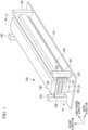
Fig. 1 is a perspective view of a welding device according to one embodiment of the present disclosure. -
Fig. 2 is a front view of the welding device illustrated inFig. 1 (when no inline plate is mounted). -
Fig. 3 is a front view of a first graphite heater and a first die illustrated inFig. 2 . -
Fig. 4 is a front view of the welding device illustrated inFig. 1 (when an inline plate is mounted). -
Fig. 5 is a cross-sectional view taken along a cut line V-V illustrated inFig. 1 . -
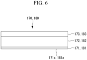
Fig. 6 is a sectional view of the inline plate or a side block. - One embodiment of the present disclosure will be described below with reference to the drawings.
- As illustrated in
Fig. 1 , thewelding device 100 is a device for performing co-consolidation (hereafter, also simply referred to as "welding") on afirst member 210 and asecond member 220. - The
first member 210 is a material containing a thermoplastic resin, specifically, which is a thermoplastic composite material such as fiber reinforced resin containing a thermoplastic resin (for example, CFRP or GFRP). - For example, the
first member 210 has a plate-like web 211 and plate-like flanges (side walls) 212 arranged vertically in the height direction from respective two opposing sides of theweb 211 and has a C-shaped or hat-shaped cross-sectional shape. - The
first member 210 is a long member formed such that, when the dimension in the width direction (the direction in which theflanges 212 face each other) is defined as 1, the dimension in the longitudinal direction (the direction in which theweb 211 and theflanges 212 extend) is 5 or greater. - For example, when the dimension in the width direction is 100 mm, the dimension in the longitudinal direction will be 500 mm or longer. Note that these numerical values are mere examples.
- The
second member 220 is a material containing a thermoplastic resin, specifically, which is a thermoplastic composite material such as fiber reinforced resin containing a thermoplastic resin (for example, CFRP or GFRP). - For example, the
second member 220 has a plate-like web 221 and plate-like flanges (side walls) 222 arranged vertically in the height direction from respective two opposing sides of theweb 221 and has a C-shaped or hat-shaped cross-sectional shape. - The
second member 220 is a long member formed such that, when the dimension in the width direction (the direction in which theflanges 222 face each other) is defined as 1, the dimension in the longitudinal direction (the direction in which theweb 221 and theflanges 222 extend) is 5 or greater. - For example, when the dimension in the width direction is 100 mm, the dimension in the longitudinal direction will be 500 mm or longer. Note that these numerical values are mere examples.
- The
first member 210 and thesecond member 220 are arranged in a state where theweb 211 and theweb 221 are stacked on each other and the outer circumferential faces thereof are in contact with each other and where each end of theflanges 212 and each end of theflanges 222 face opposite sides. - The
welding device 100 welds theweb 211 and theweb 221 to each other in thefirst member 210 and thesecond member 220 arranged in such a way. - Note that each
flange 212 is not an essential configuration in thefirst member 210 with which theweb 211 is welded. The same applies to eachflange 222 of thesecond member 220. - Further, the shapes of the
first member 210 and thesecond member 220 described above are examples, and any shapes of thefirst member 210 and thesecond member 220 may be employed as long as these shapes are in a form in which plate-like portions stacked on each other are joined together. - As illustrated in
Fig. 1 andFig. 2 , thewelding device 100 includes a first unit having a first graphite heater (heating unit) 110 and a first die (mold) 130 and a second unit having a second graphite heater (heating unit) 120 and a second die (mold) 140. - The
first member 210 and thesecond member 220 are stacked on each other and interposed between the first unit and the second unit. - In this state, the first unit is in a form such that the first unit is contained inside between the
flanges 212 of thefirst member 210, and the second unit is in a form such that the second unit is contained inside between theflanges 222 of thesecond member 220. - Accordingly, the
first member 210 and thesecond member 220 can be pressed by the first unit and the second unit. - The first unit and the second unit are arranged symmetrically about the interface between the
first member 210 and the second member 220 (the joining interface in welding). - The first unit is a unit arranged below the
first member 210 and thesecond member 220 and has thefirst graphite heater 110 and thefirst die 130. - The
first die 130 is a long metal block extending in the longitudinal direction of thefirst member 210. - The
first graphite heater 110 is provided to thefirst die 130 so that aheat insulation material 150 is interposed between thefirst die 130 and thefirst graphite heater 110. - The
first graphite heater 110 is a device that heats thefirst member 210. The configuration of thefirst graphite heater 110 will be described later. - The top face of the
first graphite heater 110 is a surface that comes into contact with theweb 211 of thefirst member 210. - The second unit is arranged symmetrically with the first unit about the joining interface, and the under face of the
second graphite heater 120 is a surface that comes into contact with theweb 221 of thesecond member 220, as already described. That is, the second unit and the like are arranged in a form such that the first unit and thefirst member 210 are vertically inversed with respect to the joining interface. Thus, the detailed description for the second unit will be omitted. - Note that the
second graphite heater 120, thesecond die 140, and aheat insulation material 160 of the second unit correspond to thefirst graphite heater 110, thefirst die 130, and theheat insulation material 150 of the first unit. - The
welding device 100 includes thefirst graphite heater 110 and thesecond graphite heater 120 as devices for heating thefirst member 210 and thesecond member 220. - The configuration of the
first graphite heater 110 and thesecond graphite heater 120 will be described below. - As illustrated in
Fig. 3 , thefirst graphite heater 110 is configured such that a graphite sheet (heat generating body) 114, two insulating materials (insulating layers) 113, an inner cover (contact layer) 112, and an outer cover (contact layer) 111 are laminated in layers. - The
graphite sheet 114 is a sheet-like heat generating body that generates heat by electric power. The electric power supplied to thegraphite sheet 114, that is, the heating value of thegraphite sheet 114 is controlled by a control unit (not illustrate). - Note that the heat generating body is not limited to the
graphite sheet 114 and may be any sheet-like body that generates heat by electric power. - The
graphite sheet 114 is interposed and held between the twoinsulating materials 113. - The insulating
materials 113 are members for electrical insulation between thegraphite sheet 114 and theouter cover 111 and between the graphite sheet and theinner cover 112. The resistance of the insulatingmaterial 113 is 200 MΩ or higher at normal temperature. - The structure in which the
graphite sheet 114 is interposed between the insulatingmaterials 113 is interposed and held between theouter cover 111 and theinner cover 112. - The
outer cover 111 is a plate whose cross-sectional shape is a C-shape and whose side plates cover the sides of the structure in which thegraphite sheet 114 is interposed between the insulatingmaterials 113 and the sides of theinner cover 112. Further, theouter cover 111 is also a portion that comes into contact with thefirst member 210 as thefirst graphite heater 110. - A material having good thermal conductive property and predetermined rigidity is employed for the material of the
outer cover 111. An example of a physical property for evaluating the thermal conductive property may be thermal conductivity, which is preferably 10 W/m×K or greater at normal temperature in the present embodiment. Further, an example of a physical property for evaluating the rigidity is Young's modulus, which is preferably 30 GPa or greater in the present embodiment. An example of such a material may be a copper-based metal, high-thermal conductivity fine ceramics such as aluminum nitride or silicon carbide, or the like but is not limited thereto. - The
inner cover 112 is a flat plate. Further, theinner cover 112 is also a portion that comes into contact with theheat insulation material 150 as thefirst graphite heater 110. - A material satisfying the same physical properties as the
outer cover 111 is employed for the material of theinner cover 112. Note that these materials are not necessarily required to be the same material as long as they satisfy the above physical property. - In the
first graphite heater 110 configured as described above, the side plates of theouter cover 111 cover the sides of theheat insulation material 150 and thefirst die 130. In this state, aheat insulation material 151 may be provided between each side plate of theouter cover 111 and theheat insulation material 150 and between each side plate of theouter cover 111 and thefirst die 130. - In the
first graphite heater 110, the total thickness of a portion of thelaminated graphite sheet 114, two insulatingmaterials 113,inner cover 112, andouter cover 111 is about 3 mm or less. - Further, when each element forming the
first graphite heater 110 is focused on in detail, it is preferable that the thickness of thegraphite sheet 114 be 0.3 mm or less, the thickness of the insulatingmaterial 113 be 0.3 mm or less, and each thickness of theinner cover 112 and theouter cover 111 be 1 mm or less. - Note that, instead of the
graphite sheet 114, a different sheet-like heat generating body may be employed. An example of such a different heat generating body may be a metal thin-film heater or a micro ceramic heater. - Further, the
inner cover 112 may be omitted from thefirst graphite heater 110. In contrast, theouter cover 111 is essential for ensuring accuracy as a contact face to thefirst member 210. - The
second graphite heater 120 is configured such that agraphite sheet 124, two insulating materials (insulating layers) 123, an inner cover (contact layer) 122, and an outer cover (contact layer) 121 are laminated in layers. - These components correspond to the
graphite sheet 114, the insulatingmaterials 113, theinner cover 112, and theouter cover 111 of thefirst graphite heater 110, and thesecond graphite heater 120 employs the same configuration as thefirst graphite heater 110. Thus, the detailed description for thesecond graphite heater 120 will be omitted. - The
second graphite heater 120 configured as described above is provided such that the side plates of theouter cover 121 cover the sides of theheat insulation material 160 and thesecond die 140. - In this state, a
heat insulation material 161 may be provided between each side plate of theouter cover 121 and theheat insulation material 160 and between each side plate of theouter cover 121 andsecond die 140. - As illustrated in
Fig. 1 andFig. 4 toFig. 6 , thewelding device 100 may includeinline plates 170. - The
inline plates 170 are plates attached to both end faces in the longitudinal direction of thefirst die 130. - The
inline plates 170 are fastened to the end faces in the longitudinal direction of thefirst die 130 bybolts 193, for example. - As illustrated in
Fig. 6 , theinline plate 170 is configured such that a plate 171, a heat insulation material 172, and a plate 173 are laminated. - As the material of the plate 171 and the plate 173, a material having high strength and heat resistance is employed. An example of such a material may be a metal such as iron.
- As illustrated in
Fig. 5 , in a state where theinline plates 170 are attached to thefirst die 130, the surface (end contact face) 171a of each plate 171 abuts against the end faces in the longitudinal direction of thefirst member 210 and thesecond member 220 and determines the position in the longitudinal direction of thefirst member 210 and thesecond member 220. Note that, inFig. 5 , only thefirst member 210 and thesecond member 220 are hatched for the purpose of illustration. - Accordingly, even when the melted resin causes a state where the stacked
first member 210 andsecond member 220 are likely to be displaced relative to each other, such displacement can be prevented. - Note that the
inline plate 170 may abut against the end faces of thefirst graphite heater 110 and thesecond graphite heater 120 in addition to thefirst member 210 and thesecond member 220. - It is preferable to make the plate 171 as thin as possible within a range where it is possible to ensure sufficient strength to prevent deformation even when the plate 171 comes into contact with the
first member 210 and thesecond member 220. This can reduce the volume of the plate 171 that serves as a heat capacity body. - On the other hand, the plate 173 is not required to be thin as with the plate 171 if the heat insulation material 172 as a heat insulation layer is provided between the plates 171 and 173. The plate 173 may rather be thicker than the plate 171 in order to ensure the rigidity as a function of the
inline plate 170. - As illustrated in
Fig. 4 , theinline plate 170 is fastened to thefirst die 130 but not fastened to thesecond die 140. Instead, aslot 174 extending in the height direction (seeFig. 1 ) of thewelding device 100 is formed in the upper part of the inline plate 170 (at a position overlapping the second die 140). Apin 194 fixed to thesecond die 140 is inserted through theslot 174. There is a play in the height direction but no play in the width direction between theslot 174 and thepin 194. - With this configuration, the
second die 140 is positioned in the width direction with respect to thefirst die 130 via theinline plate 170, and thesecond die 140 is movable within a range of theslot 174 in the height direction with respect to thefirst die 130. - The reason why the
second die 140 is made movable is to ensure a motion margin needed for pushing thesecond die 140 to thefirst die 130 side when pressing thefirst member 210 and thesecond member 220. - Note that the
inline plate 170 is not necessarily required to be fastened to thefirst die 130 and may be fastened to thebase plate 191 as long as thefirst die 130 and thebase plate 191 are fixed to each other, for example. - As illustrated in
Fig. 1 ,Fig. 2 , andFig. 6 , thewelding device 100 may include side blocks 180. - Each
side block 180 is a plate extending in the longitudinal direction of thewelding device 100. - The
side block 180 is attached toposts 192 erected on thebase plate 191 so as to be located on both sides of theflange 212 of thefirst member 210 and theflange 222 of thesecond member 220. - As illustrated in
Fig. 6 , theside block 180 is configured such that a plate 181, a heat insulation material 182, and a plate 183 are laminated. - As illustrated in
Fig. 1 andFig. 2 , in a state where theside block 180 is attached to theposts 192, the surface (side contact face) 181a of each plate 181 abuts against the side faces of theflange 212 of thefirst member 210 and theflange 222 of thesecond member 220 and determines the position in the width direction of thefirst member 210 and thesecond member 220. - Accordingly, even when the melted resin causes a state where the stacked
first member 210 andsecond member 220 are likely to be displaced relative to each other, such displacement can be prevented. - It is preferable to make the plate 181 as thin as possible within a range where it is possible to ensure sufficient strength to prevent deformation even when the plate 181 comes into contact with the
first member 210 and thesecond member 220. This can reduce the volume of the plate 181 that serves as a heat capacity body. - On the other hand, the plate 183 is not required to be thin as with the plate 181 if the heat insulation material 182 as a heat insulation layer is provided between the plates 181 and 183. The plate 183 may rather be thicker than the plate 181 in order to ensure the rigidity as a function of the
side block 180. - As illustrated in
Fig. 2 , thewelding device 100 may includeplungers - Each
plunger 131 is a member that can push theflange 212 of thefirst member 210 in a direction away from thefirst die 130 in the width direction. For example, theplunger 131 is a component having a spring as an elastic body. - For example, the
plunger 131 may be provided to the side face of theouter cover 111 covering the side of thefirst die 130 or may be provided to the side face of thefirst die 130. - Accordingly, even when the melted resin causes a state where the
flange 212 is likely to incline toward thefirst die 130, such inclination can be prevented. - Note that, since the
plunger 141 is provided on thesecond die 140 side but employs the same configuration as theplunger 131, the detailed description for theplunger 141 will be omitted. - The
welding device 100 configured as described above welds thefirst member 210 and thesecond member 220 as follows. - That is, first, as illustrated in
Fig. 1 andFig. 2 , thefirst member 210 and thesecond member 220 are set in thewelding device 100 so that theweb 211 of thefirst member 210 and theweb 221 of thesecond member 220 are stacked on each other and the outer faces thereof come into contact with each other. - In this step, the
inline plates 170, the side blocks 180, and theplungers - Next, the
first graphite heater 110 and thesecond graphite heater 120 are caused to generate heat. In detail, electric power is supplied to thegraphite sheet 114 and thegraphite sheet 124 to cause thegraphite sheet 114 and thegraphite sheet 124 to generate heat. - Further, to consolidate the melted thermoplastic resin, the
second die 140 is pushed against thefirst die 130 side to press thefirst member 210 and thesecond member 220. - The
first member 210 and thesecond member 220 are then cooled, and thereby thefirst member 210 and thesecond member 220 are integrated. - According to the present embodiment, the following advantageous effects are achieved.
- Since the
first graphite heater 110 is configured such that the structure in which thegraphite sheet 114 is interposed between the insulatingmaterials 113 is interposed between theouter cover 111 and theinner cover 112, the heat capacity body surrounding thegraphite sheet 114 as a heat generating body can be made compact. - This eliminates the need for heating a useless heat capacity body. Thus, a time required for rise and fall of the temperature is shortened, thereby efficient welding in terms of time can be realized, and efficient welding in terms of energy (electric power) can be realized. The same applies to the
second graphite heater 120. - Further, if the
heat insulation material 150 and theheat insulation material 160 are provided, the amount of heat transferred from thefirst graphite heater 110 to thefirst die 130 and the amount of heat transferred from thesecond graphite heater 120 to thesecond die 140 can be suppressed. - Accordingly, the heat from the
first graphite heater 110 and thesecond graphite heater 120 can be efficiently and intensively transferred to thefirst member 210 and the second member 220 (welding portion). - Further, if the
inline plate 170 is provided, even when the melted resin causes a state where the stackedfirst member 210 andsecond member 220 are likely to be displaced relative to each other in the longitudinal direction, such displacement can be prevented. - Further, if the
inline plate 170 has the heat insulation material 172, heat dissipation via theinline plate 170 from the end faces of thefirst member 210 and thesecond member 220, the end faces of thefirst graphite heater 110 and thesecond graphite heater 120, and the end faces of thefirst die 130 and thesecond die 140 can be suppressed. - Further, if the
side block 180 is provided, even when the melted resin causes a state where the stackedfirst member 210 andsecond member 220 are likely to be displaced relative to each other in the width direction, such displacement can be prevented. - Further, if the
side block 180 has the heat insulation material 182, heat dissipation via the side block 180 from the side faces of thefirst member 210 and thesecond member 220 can be suppressed. - Further, if the
plungers flanges - Note that a welding step automated by a robot may be implemented by attaching the first unit having the
first graphite heater 110 and thefirst die 130 and the second unit having thesecond graphite heater 120 and thesecond die 140 to gripping parts of robot arms, respectively. Such a robot is incorporated in a production line of a structure employed by an aircraft, for example. - One embodiment as described above is recognized as follows, for example.
- That is, a welding device (100) according to one aspect of the present disclosure is a welding device for welding stacked materials (210, 220) to each other that contain a thermoplastic resin, the welding device includes: a heating unit (110, 120) configured to come into contact with each material; and a mold (130, 140) configured to interpose the heating unit between the material and the mold, the heating unit has a graphite sheet (114, 124) configured to generate heat by electric power, insulating layers (113, 123), and a contact layer (111, 121) and is configured such that a structure in which the graphite sheet is interposed between the insulating layers is laminated on the contact layer, and the contact layer has thermal conductivity of 10 W/m×K or greater at normal temperature and Young's modulus of 30 GPa or greater at normal temperature.
- According to the welding device of the present aspect, since the heating unit configured to come into contact with each material containing the thermoplastic resin and the mold configured to interpose the heating unit between the material and the mold are provided, the heating unit has the graphite sheet configured to generate heat by electric power, the insulating layers, and the contact layer and is configured such that the structure in which the graphite sheet is interposed between the insulating layers is laminated on the contact layer, and the contact layer has thermal conductivity of 10 W/m×K or greater at normal temperature and Young's modulus of 30 GPa or greater at normal temperature, the heat capacity body of the heating unit surrounding the graphite sheet as a heat generating body can be made compact.
- This eliminates the need for heating a useless heat capacity body. Thus, a time required for rise and fall of the temperature is shortened, thereby efficient welding in terms of time can be realized, and efficient welding in terms of energy (electric power) can be realized.
- Further, the welding device according to one aspect of the present disclosure includes a heat insulation material (150, 160) provided between the heating unit and the mold.
- According to the welding device of the present aspect, since the heat insulation material provided between the heating unit and the mold is provided, the amount of heat transferred from the heating unit to the mold can be suppressed.
- Accordingly, the heat from the heating unit can be efficiently and intensively transferred to the material (welding portion).
- Further, the welding device according to one aspect of the present disclosure includes an inline plate (170) having an end contact face (171a) configured to abut against end faces of the materials.
- According to the welding device of the present aspect, since the inline plate having the end contact face configured to abut against the end faces of the materials is provided, the materials can be positioned.
- Accordingly, even when the melted resin causes a state where the stacked materials are likely to be displaced relative to each other, such displacement can be prevented.
- Further, in the welding device according to one aspect of the present disclosure, the inline plate has a plate (171) forming the end contact face and a second heat insulation material (172) laminated on the plate.
- According to the welding device of the present aspect, since the inline plate has the plate forming the end contact face and the second heat insulation material laminated on the plate, the heat dissipation via the inline plate from the end face of the material, the end face of the heating unit, and/or the end face of the mold can be suppressed.
- Further, the welding device according to one aspect of the present disclosure includes a side block (180) having a side contact face (181a) configured to abut against side faces of the materials.
- According to the welding device of the present aspect, since the side block having the side contact face configured to abut against the side faces of the materials is provided, the materials can be positioned.
- Accordingly, even when the melted resin causes a state where the stacked materials are likely to be displaced relative to each other, such displacement can be prevented.
- Further, in the welding device according to one aspect of the present disclosure, the side block (180) has a plate (181) forming the side contact face and a third heat insulation material (182) laminated on the plate.
- According to the welding device of the present aspect, since the plate forming the side contact face and the third heat insulation material laminated on the plate are provided, the heat dissipation via the side block from the side face of the material can be suppressed.
- Further, in the welding device according to one aspect of the present disclosure, the material has a side wall (212, 222) arranged vertically so as to cover a side of the mold, and the welding device further includes a pushing member (131, 141) configured to push the side wall of the material in a direction away from the mold.
- According to the welding device of the present aspect, since the material has the side wall arranged vertically so as to cover a side of the mold, and the pushing member configured to push the side wall of the material in a direction away from the mold is provided, even when the melted resin causes a state where the side wall is likely to incline toward the mold, such inclination can be prevented.
- Further, the welding method according to one aspect of the present disclosure is a welding method for welding the materials to each other by the welding device described above, and the welding method includes steps of: causing the graphite sheet of the heating unit to generate heat; and pushing the mold to the material side.
-
- 100
- welding device
- 110
- first graphite heater (heating unit)
- 111
- outer cover (contact layer)
- 112
- inner cover (contact layer)
- 113
- insulating material (insulating layer)
- 114
- graphite sheet
- 120
- second graphite heater (heating unit)
- 121
- outer cover (contact layer)
- 122
- inner cover (contact layer)
- 123
- insulating material (insulating layer)
- 124
- graphite sheet
- 130
- first die (mold)
- 131
- plunger
- 140
- second die (mold)
- 141
- plunger
- 150
- heat insulation material
- 151
- heat insulation material
- 160
- heat insulation material
- 161
- heat insulation material
- 170
- inline plate
- 171
- plate
- 171a
- surface (end contact face)
- 172
- heat insulation material (second heat insulation material)
- 173
- plate
- 174
- slot
- 180
- side block
- 181
- plate
- 181a
- surface (side contact face)
- 182
- heat insulation material (third heat insulation material)
- 183
- plate
- 191
- base plate
- 192
- post
- 193
- bolt
- 194
- pin
- 210
- first member (material)
- 211
- web
- 212
- flange (side wall)
- 220
- second member (material)
- 221
- web
- 222
- flange (side wall)
Claims (8)
- A welding device for welding stacked materials to each other that contain a thermoplastic resin, the welding device comprising:a heating unit configured to come into contact with each of the materials; anda mold configured to interpose the heating unit between each of the materials and the mold,wherein the heating unit has a sheet-like heat generating body configured to generate heat by electric power, insulating layers, and a contact layer and is configured such that a structure in which the heat generating body is interposed between the insulating layers is laminated on the contact layer, andwherein the contact layer has thermal conductivity of 10 W/m×K or greater at normal temperature and Young's modulus of 30 GPa or greater at normal temperature.
- The welding device according to claim 1 further comprising a heat insulation material provided between the heating unit and the mold.
- The welding device according to claim 1 or 2 further comprising an inline plate having an end contact face configured to abut against end faces of the materials.
- The welding device according to claim 3, wherein the inline plate has a plate forming the end contact face and a second heat insulation material laminated on the plate.
- The welding device according to any one of claims 1 to 4 further comprising a side block having a side contact face configured to abut against side faces of the materials.
- The welding device according to claim 5, wherein the side block has a plate forming the side contact face and a third heat insulation material laminated on the plate.
- The welding device according to any one of claims 1 to 6, wherein each of the materials has a side wall arranged vertically so as to cover a side of the mold, the welding device further comprising a pushing member configured to push the side wall of each of the materials in a direction away from the mold.
- A welding method for welding the materials to each other by the welding device according to any one of claims 1 to 7, the welding method comprising:causing the heat generating body of the heating unit to generate heat; andpushing the mold to the material side.
Applications Claiming Priority (1)
| Application Number | Priority Date | Filing Date | Title |
|---|---|---|---|
| JP2021214532A JP7275246B1 (en) | 2021-12-28 | 2021-12-28 | Fusion device and fusion method |
Publications (2)
| Publication Number | Publication Date |
|---|---|
| EP4205953A1 true EP4205953A1 (en) | 2023-07-05 |
| EP4205953B1 EP4205953B1 (en) | 2024-09-11 |
Family
ID=82321485
Family Applications (1)
| Application Number | Title | Priority Date | Filing Date |
|---|---|---|---|
| EP22181229.0A Active EP4205953B1 (en) | 2021-12-28 | 2022-06-27 | Welding device and welding method |
Country Status (3)
| Country | Link |
|---|---|
| US (1) | US11999114B2 (en) |
| EP (1) | EP4205953B1 (en) |
| JP (1) | JP7275246B1 (en) |
Families Citing this family (1)
| Publication number | Priority date | Publication date | Assignee | Title |
|---|---|---|---|---|
| JP2025040523A (en) | 2023-09-12 | 2025-03-25 | 三菱重工業株式会社 | Heating Device |
Citations (4)
| Publication number | Priority date | Publication date | Assignee | Title |
|---|---|---|---|---|
| US3748207A (en) * | 1971-08-26 | 1973-07-24 | Kimberly Clark Co | Mechanism for heat sealing |
| DE102012215105A1 (en) * | 2011-08-30 | 2013-02-28 | Bielomatik Leuze Gmbh + Co. Kg | Apparatus for heat pulse welding |
| WO2020070692A1 (en) * | 2018-10-03 | 2020-04-09 | G.D Societa' Per Azioni | Welding device and method for its production |
| JP2020152110A (en) | 2019-03-19 | 2020-09-24 | ザ・ボーイング・カンパニーThe Boeing Company | Methods and systems for co-consolidation of thermoplastic composite components |
Family Cites Families (9)
| Publication number | Priority date | Publication date | Assignee | Title |
|---|---|---|---|---|
| JPS5628892Y2 (en) * | 1976-11-26 | 1981-07-09 | ||
| JP3795269B2 (en) | 1999-09-09 | 2006-07-12 | 日本アビオニクス株式会社 | Thermocompression bonding equipment |
| US9102103B2 (en) * | 2006-02-02 | 2015-08-11 | The Boeing Company | Thermoplastic composite parts having integrated metal fittings and method of making the same |
| JP4444980B2 (en) * | 2007-04-02 | 2010-03-31 | 株式会社日本製鋼所 | Mold for molding molded body and method for producing molded body using the same |
| FR2980732B1 (en) | 2011-10-04 | 2013-10-11 | Airbus Operations Sas | METHOD AND DEVICE FOR WELDING A THERMOPLASTIC STIFFENER |
| GB2535193A (en) * | 2015-02-12 | 2016-08-17 | Zodiac Seats Uk Ltd | Tool for curing a composite component |
| CN211492875U (en) | 2019-12-24 | 2020-09-15 | 广州方邦电子股份有限公司 | An integrated device manufacturing mold |
| KR102780005B1 (en) * | 2020-05-15 | 2025-03-13 | 데쿠세리아루즈 가부시키가이샤 | Thermally conductive sheet and method for manufacturing thermally conductive sheet |
| CN113306133A (en) | 2021-06-29 | 2021-08-27 | 无锡吉兴汽车声学部件科技有限公司 | Hot laminating equipment for spare plate of automobile trunk |
-
2021
- 2021-12-28 JP JP2021214532A patent/JP7275246B1/en active Active
-
2022
- 2022-06-21 US US17/845,235 patent/US11999114B2/en active Active
- 2022-06-27 EP EP22181229.0A patent/EP4205953B1/en active Active
Patent Citations (4)
| Publication number | Priority date | Publication date | Assignee | Title |
|---|---|---|---|---|
| US3748207A (en) * | 1971-08-26 | 1973-07-24 | Kimberly Clark Co | Mechanism for heat sealing |
| DE102012215105A1 (en) * | 2011-08-30 | 2013-02-28 | Bielomatik Leuze Gmbh + Co. Kg | Apparatus for heat pulse welding |
| WO2020070692A1 (en) * | 2018-10-03 | 2020-04-09 | G.D Societa' Per Azioni | Welding device and method for its production |
| JP2020152110A (en) | 2019-03-19 | 2020-09-24 | ザ・ボーイング・カンパニーThe Boeing Company | Methods and systems for co-consolidation of thermoplastic composite components |
Also Published As
| Publication number | Publication date |
|---|---|
| JP2023098045A (en) | 2023-07-10 |
| US11999114B2 (en) | 2024-06-04 |
| US20230202124A1 (en) | 2023-06-29 |
| EP4205953B1 (en) | 2024-09-11 |
| JP7275246B1 (en) | 2023-05-17 |
Similar Documents
| Publication | Publication Date | Title |
|---|---|---|
| EP2511922B1 (en) | Storage unit for storing electrical energy with a cooling element | |
| EP1841000A2 (en) | Fuel cell stack structure | |
| US10454146B2 (en) | Heat exchanger component | |
| US11165110B2 (en) | Stored electrical energy source having cooling plates arranged between the cells for emergency cooling | |
| WO2015055419A1 (en) | Battery housing, battery and method for producing a battery housing | |
| WO2022204273A1 (en) | Manufacture of heat exchangers via hybrid welding | |
| US20160056512A1 (en) | Heat exchanger component | |
| WO2013017207A1 (en) | Single cell and battery made of a plurality of single cells | |
| CN108604658A (en) | Power supply unit, vehicle using same, bus bar, and electrical connection method for battery unit using same | |
| EP4205953B1 (en) | Welding device and welding method | |
| US20170317324A1 (en) | Housing for the cell stack of a battery | |
| EP3783728B1 (en) | Battery module | |
| US8603279B2 (en) | Process and device for welding a thermoplastic stiffener | |
| JP6817361B2 (en) | Dummy cell manufacturing method and dummy cell manufacturing equipment | |
| KR20140006023A (en) | Preform fabrication apparatus, fabrication method, and preform fabricated with same method | |
| JP5594519B2 (en) | Assembled battery | |
| US9314990B2 (en) | Resin composite structure and method for producing the same | |
| JP6645801B2 (en) | Fiber-reinforced resin molded product and method for producing the same | |
| EP4122680A1 (en) | Welding device and welding method | |
| JPH0564097B2 (en) | ||
| JP6817357B2 (en) | Manufacturing method of fuel cell stack and dummy cell | |
| CN116670893A (en) | Cooling device for electric accumulator including gravity heat pipe, electric accumulator and motor vehicle | |
| US10546700B2 (en) | Laminate-type power storage element and method of implementing the same | |
| JP6977333B2 (en) | Power storage device and manufacturing method of power storage device | |
| JPH11354097A (en) | Battery joining equipment |
Legal Events
| Date | Code | Title | Description |
|---|---|---|---|
| PUAI | Public reference made under article 153(3) epc to a published international application that has entered the european phase |
Free format text: ORIGINAL CODE: 0009012 |
|
| STAA | Information on the status of an ep patent application or granted ep patent |
Free format text: STATUS: REQUEST FOR EXAMINATION WAS MADE |
|
| 17P | Request for examination filed |
Effective date: 20230306 |
|
| AK | Designated contracting states |
Kind code of ref document: A1 Designated state(s): AL AT BE BG CH CY CZ DE DK EE ES FI FR GB GR HR HU IE IS IT LI LT LU LV MC MK MT NL NO PL PT RO RS SE SI SK SM TR |
|
| RIN1 | Information on inventor provided before grant (corrected) |
Inventor name: IWANAGA, TOMOYA Inventor name: MATSUOKA, JUN Inventor name: YAMAGUCHI, SHO Inventor name: OZAKI, RYOTA |
|
| GRAP | Despatch of communication of intention to grant a patent |
Free format text: ORIGINAL CODE: EPIDOSNIGR1 |
|
| STAA | Information on the status of an ep patent application or granted ep patent |
Free format text: STATUS: GRANT OF PATENT IS INTENDED |
|
| RIC1 | Information provided on ipc code assigned before grant |
Ipc: B29L 31/30 20060101ALN20240301BHEP Ipc: B29C 65/30 20060101ALI20240301BHEP Ipc: B29C 65/00 20060101ALI20240301BHEP Ipc: B29C 65/22 20060101AFI20240301BHEP |
|
| INTG | Intention to grant announced |
Effective date: 20240410 |
|
| GRAS | Grant fee paid |
Free format text: ORIGINAL CODE: EPIDOSNIGR3 |
|
| GRAA | (expected) grant |
Free format text: ORIGINAL CODE: 0009210 |
|
| STAA | Information on the status of an ep patent application or granted ep patent |
Free format text: STATUS: THE PATENT HAS BEEN GRANTED |
|
| AK | Designated contracting states |
Kind code of ref document: B1 Designated state(s): AL AT BE BG CH CY CZ DE DK EE ES FI FR GB GR HR HU IE IS IT LI LT LU LV MC MK MT NL NO PL PT RO RS SE SI SK SM TR |
|
| REG | Reference to a national code |
Ref country code: GB Ref legal event code: FG4D |
|
| REG | Reference to a national code |
Ref country code: CH Ref legal event code: EP |
|
| REG | Reference to a national code |
Ref country code: DE Ref legal event code: R096 Ref document number: 602022005990 Country of ref document: DE |
|
| REG | Reference to a national code |
Ref country code: IE Ref legal event code: FG4D |
|
| REG | Reference to a national code |
Ref country code: LT Ref legal event code: MG9D |
|
| PG25 | Lapsed in a contracting state [announced via postgrant information from national office to epo] |
Ref country code: NO Free format text: LAPSE BECAUSE OF FAILURE TO SUBMIT A TRANSLATION OF THE DESCRIPTION OR TO PAY THE FEE WITHIN THE PRESCRIBED TIME-LIMIT Effective date: 20241211 |
|
| REG | Reference to a national code |
Ref country code: NL Ref legal event code: MP Effective date: 20240911 |
|
| PG25 | Lapsed in a contracting state [announced via postgrant information from national office to epo] |
Ref country code: GR Free format text: LAPSE BECAUSE OF FAILURE TO SUBMIT A TRANSLATION OF THE DESCRIPTION OR TO PAY THE FEE WITHIN THE PRESCRIBED TIME-LIMIT Effective date: 20241212 Ref country code: FI Free format text: LAPSE BECAUSE OF FAILURE TO SUBMIT A TRANSLATION OF THE DESCRIPTION OR TO PAY THE FEE WITHIN THE PRESCRIBED TIME-LIMIT Effective date: 20240911 |
|
| PG25 | Lapsed in a contracting state [announced via postgrant information from national office to epo] |
Ref country code: BG Free format text: LAPSE BECAUSE OF FAILURE TO SUBMIT A TRANSLATION OF THE DESCRIPTION OR TO PAY THE FEE WITHIN THE PRESCRIBED TIME-LIMIT Effective date: 20240911 |
|
| PG25 | Lapsed in a contracting state [announced via postgrant information from national office to epo] |
Ref country code: LV Free format text: LAPSE BECAUSE OF FAILURE TO SUBMIT A TRANSLATION OF THE DESCRIPTION OR TO PAY THE FEE WITHIN THE PRESCRIBED TIME-LIMIT Effective date: 20240911 |
|
| PG25 | Lapsed in a contracting state [announced via postgrant information from national office to epo] |
Ref country code: HR Free format text: LAPSE BECAUSE OF FAILURE TO SUBMIT A TRANSLATION OF THE DESCRIPTION OR TO PAY THE FEE WITHIN THE PRESCRIBED TIME-LIMIT Effective date: 20240911 |
|
| PG25 | Lapsed in a contracting state [announced via postgrant information from national office to epo] |
Ref country code: RS Free format text: LAPSE BECAUSE OF FAILURE TO SUBMIT A TRANSLATION OF THE DESCRIPTION OR TO PAY THE FEE WITHIN THE PRESCRIBED TIME-LIMIT Effective date: 20241211 Ref country code: ES Free format text: LAPSE BECAUSE OF FAILURE TO SUBMIT A TRANSLATION OF THE DESCRIPTION OR TO PAY THE FEE WITHIN THE PRESCRIBED TIME-LIMIT Effective date: 20240911 |
|
| PG25 | Lapsed in a contracting state [announced via postgrant information from national office to epo] |
Ref country code: RS Free format text: LAPSE BECAUSE OF FAILURE TO SUBMIT A TRANSLATION OF THE DESCRIPTION OR TO PAY THE FEE WITHIN THE PRESCRIBED TIME-LIMIT Effective date: 20241211 Ref country code: NO Free format text: LAPSE BECAUSE OF FAILURE TO SUBMIT A TRANSLATION OF THE DESCRIPTION OR TO PAY THE FEE WITHIN THE PRESCRIBED TIME-LIMIT Effective date: 20241211 Ref country code: LV Free format text: LAPSE BECAUSE OF FAILURE TO SUBMIT A TRANSLATION OF THE DESCRIPTION OR TO PAY THE FEE WITHIN THE PRESCRIBED TIME-LIMIT Effective date: 20240911 Ref country code: HR Free format text: LAPSE BECAUSE OF FAILURE TO SUBMIT A TRANSLATION OF THE DESCRIPTION OR TO PAY THE FEE WITHIN THE PRESCRIBED TIME-LIMIT Effective date: 20240911 Ref country code: GR Free format text: LAPSE BECAUSE OF FAILURE TO SUBMIT A TRANSLATION OF THE DESCRIPTION OR TO PAY THE FEE WITHIN THE PRESCRIBED TIME-LIMIT Effective date: 20241212 Ref country code: FI Free format text: LAPSE BECAUSE OF FAILURE TO SUBMIT A TRANSLATION OF THE DESCRIPTION OR TO PAY THE FEE WITHIN THE PRESCRIBED TIME-LIMIT Effective date: 20240911 Ref country code: ES Free format text: LAPSE BECAUSE OF FAILURE TO SUBMIT A TRANSLATION OF THE DESCRIPTION OR TO PAY THE FEE WITHIN THE PRESCRIBED TIME-LIMIT Effective date: 20240911 Ref country code: BG Free format text: LAPSE BECAUSE OF FAILURE TO SUBMIT A TRANSLATION OF THE DESCRIPTION OR TO PAY THE FEE WITHIN THE PRESCRIBED TIME-LIMIT Effective date: 20240911 |
|
| REG | Reference to a national code |
Ref country code: AT Ref legal event code: MK05 Ref document number: 1722342 Country of ref document: AT Kind code of ref document: T Effective date: 20240911 |
|
| PG25 | Lapsed in a contracting state [announced via postgrant information from national office to epo] |
Ref country code: NL Free format text: LAPSE BECAUSE OF FAILURE TO SUBMIT A TRANSLATION OF THE DESCRIPTION OR TO PAY THE FEE WITHIN THE PRESCRIBED TIME-LIMIT Effective date: 20240911 |
|
| PG25 | Lapsed in a contracting state [announced via postgrant information from national office to epo] |
Ref country code: IS Free format text: LAPSE BECAUSE OF FAILURE TO SUBMIT A TRANSLATION OF THE DESCRIPTION OR TO PAY THE FEE WITHIN THE PRESCRIBED TIME-LIMIT Effective date: 20250111 Ref country code: PT Free format text: LAPSE BECAUSE OF FAILURE TO SUBMIT A TRANSLATION OF THE DESCRIPTION OR TO PAY THE FEE WITHIN THE PRESCRIBED TIME-LIMIT Effective date: 20250113 |
|
| PG25 | Lapsed in a contracting state [announced via postgrant information from national office to epo] |
Ref country code: RO Free format text: LAPSE BECAUSE OF FAILURE TO SUBMIT A TRANSLATION OF THE DESCRIPTION OR TO PAY THE FEE WITHIN THE PRESCRIBED TIME-LIMIT Effective date: 20240911 Ref country code: SM Free format text: LAPSE BECAUSE OF FAILURE TO SUBMIT A TRANSLATION OF THE DESCRIPTION OR TO PAY THE FEE WITHIN THE PRESCRIBED TIME-LIMIT Effective date: 20240911 |
|
| PG25 | Lapsed in a contracting state [announced via postgrant information from national office to epo] |
Ref country code: AT Free format text: LAPSE BECAUSE OF FAILURE TO SUBMIT A TRANSLATION OF THE DESCRIPTION OR TO PAY THE FEE WITHIN THE PRESCRIBED TIME-LIMIT Effective date: 20240911 Ref country code: EE Free format text: LAPSE BECAUSE OF FAILURE TO SUBMIT A TRANSLATION OF THE DESCRIPTION OR TO PAY THE FEE WITHIN THE PRESCRIBED TIME-LIMIT Effective date: 20240911 |
|
| PG25 | Lapsed in a contracting state [announced via postgrant information from national office to epo] |
Ref country code: CZ Free format text: LAPSE BECAUSE OF FAILURE TO SUBMIT A TRANSLATION OF THE DESCRIPTION OR TO PAY THE FEE WITHIN THE PRESCRIBED TIME-LIMIT Effective date: 20240911 Ref country code: PL Free format text: LAPSE BECAUSE OF FAILURE TO SUBMIT A TRANSLATION OF THE DESCRIPTION OR TO PAY THE FEE WITHIN THE PRESCRIBED TIME-LIMIT Effective date: 20240911 |
|
| PG25 | Lapsed in a contracting state [announced via postgrant information from national office to epo] |
Ref country code: IT Free format text: LAPSE BECAUSE OF FAILURE TO SUBMIT A TRANSLATION OF THE DESCRIPTION OR TO PAY THE FEE WITHIN THE PRESCRIBED TIME-LIMIT Effective date: 20240911 Ref country code: SK Free format text: LAPSE BECAUSE OF FAILURE TO SUBMIT A TRANSLATION OF THE DESCRIPTION OR TO PAY THE FEE WITHIN THE PRESCRIBED TIME-LIMIT Effective date: 20240911 |
|
| REG | Reference to a national code |
Ref country code: DE Ref legal event code: R097 Ref document number: 602022005990 Country of ref document: DE |
|
| PGFP | Annual fee paid to national office [announced via postgrant information from national office to epo] |
Ref country code: DE Payment date: 20250429 Year of fee payment: 4 |
|
| PG25 | Lapsed in a contracting state [announced via postgrant information from national office to epo] |
Ref country code: DK Free format text: LAPSE BECAUSE OF FAILURE TO SUBMIT A TRANSLATION OF THE DESCRIPTION OR TO PAY THE FEE WITHIN THE PRESCRIBED TIME-LIMIT Effective date: 20240911 |
|
| PGFP | Annual fee paid to national office [announced via postgrant information from national office to epo] |
Ref country code: FR Payment date: 20250508 Year of fee payment: 4 |
|
| PLBE | No opposition filed within time limit |
Free format text: ORIGINAL CODE: 0009261 |
|
| STAA | Information on the status of an ep patent application or granted ep patent |
Free format text: STATUS: NO OPPOSITION FILED WITHIN TIME LIMIT |
|
| 26N | No opposition filed |
Effective date: 20250612 |
|
| PG25 | Lapsed in a contracting state [announced via postgrant information from national office to epo] |
Ref country code: SE Free format text: LAPSE BECAUSE OF FAILURE TO SUBMIT A TRANSLATION OF THE DESCRIPTION OR TO PAY THE FEE WITHIN THE PRESCRIBED TIME-LIMIT Effective date: 20240911 |
|
| REG | Reference to a national code |
Ref country code: CH Ref legal event code: H13 Free format text: ST27 STATUS EVENT CODE: U-0-0-H10-H13 (AS PROVIDED BY THE NATIONAL OFFICE) Effective date: 20260127 |
|
| PG25 | Lapsed in a contracting state [announced via postgrant information from national office to epo] |
Ref country code: MC Free format text: LAPSE BECAUSE OF FAILURE TO SUBMIT A TRANSLATION OF THE DESCRIPTION OR TO PAY THE FEE WITHIN THE PRESCRIBED TIME-LIMIT Effective date: 20240911 |
|
| PG25 | Lapsed in a contracting state [announced via postgrant information from national office to epo] |
Ref country code: LU Free format text: LAPSE BECAUSE OF NON-PAYMENT OF DUE FEES Effective date: 20250627 |
|
| REG | Reference to a national code |
Ref country code: BE Ref legal event code: MM Effective date: 20250630 |
|
| PG25 | Lapsed in a contracting state [announced via postgrant information from national office to epo] |
Ref country code: IE Free format text: LAPSE BECAUSE OF NON-PAYMENT OF DUE FEES Effective date: 20250627 |
|
| PG25 | Lapsed in a contracting state [announced via postgrant information from national office to epo] |
Ref country code: BE Free format text: LAPSE BECAUSE OF NON-PAYMENT OF DUE FEES Effective date: 20250630 |
|
| PG25 | Lapsed in a contracting state [announced via postgrant information from national office to epo] |
Ref country code: CH Free format text: LAPSE BECAUSE OF NON-PAYMENT OF DUE FEES Effective date: 20250630 |