EP4205926A1 - Electrode cutting apparatus including detached foreign substance removing unit - Google Patents
Electrode cutting apparatus including detached foreign substance removing unit Download PDFInfo
- Publication number
- EP4205926A1 EP4205926A1 EP21862124.1A EP21862124A EP4205926A1 EP 4205926 A1 EP4205926 A1 EP 4205926A1 EP 21862124 A EP21862124 A EP 21862124A EP 4205926 A1 EP4205926 A1 EP 4205926A1
- Authority
- EP
- European Patent Office
- Prior art keywords
- unit
- suction
- cutter
- cutting apparatus
- blow
- Prior art date
- Legal status (The legal status is an assumption and is not a legal conclusion. Google has not performed a legal analysis and makes no representation as to the accuracy of the status listed.)
- Granted
Links
Images


Classifications
-
- B—PERFORMING OPERATIONS; TRANSPORTING
- B26—HAND CUTTING TOOLS; CUTTING; SEVERING
- B26D—CUTTING; DETAILS COMMON TO MACHINES FOR PERFORATING, PUNCHING, CUTTING-OUT, STAMPING-OUT OR SEVERING
- B26D7/00—Details of apparatus for cutting, cutting-out, stamping-out, punching, perforating, or severing by means other than cutting
- B26D7/18—Means for removing cut-out material or waste
- B26D7/1845—Means for removing cut-out material or waste by non mechanical means
-
- B—PERFORMING OPERATIONS; TRANSPORTING
- B26—HAND CUTTING TOOLS; CUTTING; SEVERING
- B26D—CUTTING; DETAILS COMMON TO MACHINES FOR PERFORATING, PUNCHING, CUTTING-OUT, STAMPING-OUT OR SEVERING
- B26D7/00—Details of apparatus for cutting, cutting-out, stamping-out, punching, perforating, or severing by means other than cutting
- B26D7/18—Means for removing cut-out material or waste
- B26D7/1845—Means for removing cut-out material or waste by non mechanical means
- B26D7/1854—Means for removing cut-out material or waste by non mechanical means by air under pressure
-
- B—PERFORMING OPERATIONS; TRANSPORTING
- B26—HAND CUTTING TOOLS; CUTTING; SEVERING
- B26D—CUTTING; DETAILS COMMON TO MACHINES FOR PERFORATING, PUNCHING, CUTTING-OUT, STAMPING-OUT OR SEVERING
- B26D1/00—Cutting through work characterised by the nature or movement of the cutting member or particular materials not otherwise provided for; Apparatus or machines therefor; Cutting members therefor
- B26D1/01—Cutting through work characterised by the nature or movement of the cutting member or particular materials not otherwise provided for; Apparatus or machines therefor; Cutting members therefor involving a cutting member which does not travel with the work
- B26D1/04—Cutting through work characterised by the nature or movement of the cutting member or particular materials not otherwise provided for; Apparatus or machines therefor; Cutting members therefor involving a cutting member which does not travel with the work having a linearly-movable cutting member
- B26D1/06—Cutting through work characterised by the nature or movement of the cutting member or particular materials not otherwise provided for; Apparatus or machines therefor; Cutting members therefor involving a cutting member which does not travel with the work having a linearly-movable cutting member wherein the cutting member reciprocates
- B26D1/08—Cutting through work characterised by the nature or movement of the cutting member or particular materials not otherwise provided for; Apparatus or machines therefor; Cutting members therefor involving a cutting member which does not travel with the work having a linearly-movable cutting member wherein the cutting member reciprocates of the guillotine type
- B26D1/09—Cutting through work characterised by the nature or movement of the cutting member or particular materials not otherwise provided for; Apparatus or machines therefor; Cutting members therefor involving a cutting member which does not travel with the work having a linearly-movable cutting member wherein the cutting member reciprocates of the guillotine type with a plurality of cutting members
- B26D1/095—Cutting through work characterised by the nature or movement of the cutting member or particular materials not otherwise provided for; Apparatus or machines therefor; Cutting members therefor involving a cutting member which does not travel with the work having a linearly-movable cutting member wherein the cutting member reciprocates of the guillotine type with a plurality of cutting members for thin material, e.g. for sheets, strips or the like
-
- B—PERFORMING OPERATIONS; TRANSPORTING
- B26—HAND CUTTING TOOLS; CUTTING; SEVERING
- B26D—CUTTING; DETAILS COMMON TO MACHINES FOR PERFORATING, PUNCHING, CUTTING-OUT, STAMPING-OUT OR SEVERING
- B26D1/00—Cutting through work characterised by the nature or movement of the cutting member or particular materials not otherwise provided for; Apparatus or machines therefor; Cutting members therefor
- B26D1/56—Cutting through work characterised by the nature or movement of the cutting member or particular materials not otherwise provided for; Apparatus or machines therefor; Cutting members therefor involving a cutting member which travels with the work otherwise than in the direction of the cut, i.e. flying cutter
- B26D1/60—Cutting through work characterised by the nature or movement of the cutting member or particular materials not otherwise provided for; Apparatus or machines therefor; Cutting members therefor involving a cutting member which travels with the work otherwise than in the direction of the cut, i.e. flying cutter and is mounted on a movable carriage
-
- B—PERFORMING OPERATIONS; TRANSPORTING
- B26—HAND CUTTING TOOLS; CUTTING; SEVERING
- B26D—CUTTING; DETAILS COMMON TO MACHINES FOR PERFORATING, PUNCHING, CUTTING-OUT, STAMPING-OUT OR SEVERING
- B26D5/00—Arrangements for operating and controlling machines or devices for cutting, cutting-out, stamping-out, punching, perforating, or severing by means other than cutting
- B26D5/02—Means for moving the cutting member into its operative position for cutting
-
- B—PERFORMING OPERATIONS; TRANSPORTING
- B26—HAND CUTTING TOOLS; CUTTING; SEVERING
- B26D—CUTTING; DETAILS COMMON TO MACHINES FOR PERFORATING, PUNCHING, CUTTING-OUT, STAMPING-OUT OR SEVERING
- B26D7/00—Details of apparatus for cutting, cutting-out, stamping-out, punching, perforating, or severing by means other than cutting
- B26D7/01—Means for holding or positioning work
- B26D7/018—Holding the work by suction
-
- B—PERFORMING OPERATIONS; TRANSPORTING
- B26—HAND CUTTING TOOLS; CUTTING; SEVERING
- B26D—CUTTING; DETAILS COMMON TO MACHINES FOR PERFORATING, PUNCHING, CUTTING-OUT, STAMPING-OUT OR SEVERING
- B26D7/00—Details of apparatus for cutting, cutting-out, stamping-out, punching, perforating, or severing by means other than cutting
- B26D7/01—Means for holding or positioning work
- B26D7/02—Means for holding or positioning work with clamping means
-
- B—PERFORMING OPERATIONS; TRANSPORTING
- B26—HAND CUTTING TOOLS; CUTTING; SEVERING
- B26D—CUTTING; DETAILS COMMON TO MACHINES FOR PERFORATING, PUNCHING, CUTTING-OUT, STAMPING-OUT OR SEVERING
- B26D7/00—Details of apparatus for cutting, cutting-out, stamping-out, punching, perforating, or severing by means other than cutting
- B26D7/06—Arrangements for feeding or delivering work of other than sheet, web, or filamentary form
- B26D7/0625—Arrangements for feeding or delivering work of other than sheet, web, or filamentary form by endless conveyors, e.g. belts
- B26D7/0633—Arrangements for feeding or delivering work of other than sheet, web, or filamentary form by endless conveyors, e.g. belts by grippers
-
- B—PERFORMING OPERATIONS; TRANSPORTING
- B26—HAND CUTTING TOOLS; CUTTING; SEVERING
- B26D—CUTTING; DETAILS COMMON TO MACHINES FOR PERFORATING, PUNCHING, CUTTING-OUT, STAMPING-OUT OR SEVERING
- B26D7/00—Details of apparatus for cutting, cutting-out, stamping-out, punching, perforating, or severing by means other than cutting
- B26D7/18—Means for removing cut-out material or waste
- B26D7/1845—Means for removing cut-out material or waste by non mechanical means
- B26D7/1863—Means for removing cut-out material or waste by non mechanical means by suction
-
- B—PERFORMING OPERATIONS; TRANSPORTING
- B26—HAND CUTTING TOOLS; CUTTING; SEVERING
- B26F—PERFORATING; PUNCHING; CUTTING-OUT; STAMPING-OUT; SEVERING BY MEANS OTHER THAN CUTTING
- B26F1/00—Perforating; Punching; Cutting-out; Stamping-out; Apparatus therefor
- B26F1/38—Cutting-out; Stamping-out
- B26F1/40—Cutting-out; Stamping-out using a press, e.g. of the ram type
-
- H—ELECTRICITY
- H01—ELECTRIC ELEMENTS
- H01M—PROCESSES OR MEANS, e.g. BATTERIES, FOR THE DIRECT CONVERSION OF CHEMICAL ENERGY INTO ELECTRICAL ENERGY
- H01M10/00—Secondary cells; Manufacture thereof
- H01M10/04—Construction or manufacture in general
-
- H—ELECTRICITY
- H01—ELECTRIC ELEMENTS
- H01M—PROCESSES OR MEANS, e.g. BATTERIES, FOR THE DIRECT CONVERSION OF CHEMICAL ENERGY INTO ELECTRICAL ENERGY
- H01M10/00—Secondary cells; Manufacture thereof
- H01M10/04—Construction or manufacture in general
- H01M10/0404—Machines for assembling batteries
-
- H—ELECTRICITY
- H01—ELECTRIC ELEMENTS
- H01M—PROCESSES OR MEANS, e.g. BATTERIES, FOR THE DIRECT CONVERSION OF CHEMICAL ENERGY INTO ELECTRICAL ENERGY
- H01M4/00—Electrodes
- H01M4/02—Electrodes composed of, or comprising, active material
- H01M4/04—Processes of manufacture in general
-
- Y—GENERAL TAGGING OF NEW TECHNOLOGICAL DEVELOPMENTS; GENERAL TAGGING OF CROSS-SECTIONAL TECHNOLOGIES SPANNING OVER SEVERAL SECTIONS OF THE IPC; TECHNICAL SUBJECTS COVERED BY FORMER USPC CROSS-REFERENCE ART COLLECTIONS [XRACs] AND DIGESTS
- Y02—TECHNOLOGIES OR APPLICATIONS FOR MITIGATION OR ADAPTATION AGAINST CLIMATE CHANGE
- Y02E—REDUCTION OF GREENHOUSE GAS [GHG] EMISSIONS, RELATED TO ENERGY GENERATION, TRANSMISSION OR DISTRIBUTION
- Y02E60/00—Enabling technologies; Technologies with a potential or indirect contribution to GHG emissions mitigation
- Y02E60/10—Energy storage using batteries
Definitions
- the present invention relates to an electrode cutting apparatus including a separated foreign matter removal unit, and more particularly to an electrode cutting apparatus including a separated foreign matter removal unit capable of immediately removing separated foreign matter generated at the time of electrode cutting through a blow unit and a suction unit configured to be repeatedly operated and stopped according to an electrode cutting operation in order to remove separated foreign matter generated when the electrode cutting apparatus performs electrode cutting.
- a lithium secondary battery which is capable of being charged and discharged, has been widely used as an energy source for wireless mobile devices or wearable devices, which are worn on bodies, and has also been used as an energy source for electric vehicles and hybrid electric vehicles presented as alternatives to existing gasoline and diesel vehicles, which cause air pollution.
- the lithium secondary battery includes an electrode assembly including a stack of a positive electrode plate coated with a positive electrode active material, a negative electrode plate coated with a negative electrode active material, and a separator located between the positive electrode plate and the negative electrode plate, the separator being configured to prevent short circuit, the separator being configured such that lithium ions (Li-ion) are movable therethrough, a battery case configured to receive the electrode assembly, and an electrolytic solution injected into the battery case such that the lithium ions are movable.
- an electrode assembly including a stack of a positive electrode plate coated with a positive electrode active material, a negative electrode plate coated with a negative electrode active material, and a separator located between the positive electrode plate and the negative electrode plate, the separator being configured to prevent short circuit, the separator being configured such that lithium ions (Li-ion) are movable therethrough, a battery case configured to receive the electrode assembly, and an electrolytic solution injected into the battery case such that the lithium ions are movable.
- the positive electrode plate and the negative electrode plate may be manufactured through a process of coating a long sheet type positive electrode sheet and a long sheet type negative electrode sheet with a positive electrode active material and a negative electrode active material, respectively, drying and rolling the active materials, and cutting the positive electrode sheet and the negative electrode sheet to a predetermined size to manufacture unit electrodes.
- a conventional electrode plate cutting apparatus configured to manufacture the unit electrodes includes a feeding unit configured to feed an electrode plate in a state of being seated and a cutter installed at one side of the feeding unit.
- the cutter is divided into an upper cutter and a lower cutter. Specifically, based on the electrode plate, the lower cutter is fixed to the lower side of the electrode plate while the upper cutter is installed at the upper side of the electrode plate, and the upper cutter is moved upwards and downwards at an electrode plate cutting position.
- the edge of the upper cutter and the edge of the lower cutter come into contact with each other to cut the electrode plate.
- FIG. 1 is a view showing operation of a conventional electrode cutting apparatus including no separated foreign matter removal unit.
- an upper cutter 110 configured to reciprocate upwards and downwards in order to cut an electrode sheet
- a stationary lower cutter 210 configured to cut the electrode sheet that enters between the lower cutter and the upper cutter.
- a gripper 400 configured to face the electrode sheet, which is supplied between the upper cutter, which performs upward and downward reciprocation, and the lower cutter, which is stationary, in parallel therewith, the gripper being configured to fix the electrode sheet.
- an upper gripper 410 formed so as to face the upper cutter in parallel therewith and a lower gripper 420 formed so as to face the lower cutter in parallel therewith.
- the upper gripper and the lower gripper may fix the electrode sheet.
- Patent Document 1 discloses a separator cutting apparatus for secondary batteries configured to cut a raw material for separators, the separator cutting apparatus including a cutting unit configured to cut the raw material for separators along a predetermined cutting line, wherein the cutting unit includes a cutter member having a first cutter end and a second cutter end, and a cleaner member configured to remove contaminants generated when the raw material for separators is cut.
- the construction of a separated foreign matter removal unit provided at an electrode cutting apparatus including an upper cutter and a lower cutter is not disclosed.
- Patent Document 2 discloses an electrode production system including upper and lower mold fixing plates and a dust collection nozzle configured to suction foreign matter, wherein the upper and lower mold fixing plates are moved through a crank shaft.
- a separated foreign matter removal unit including an electrode sheet gripper and a blow unit provided at an electrode cutting apparatus including an upper cutter and a lower cutter is not disclosed.
- an electrode cutting apparatus including a separated foreign matter removal unit configured to easily remove foreign matter generated from an electrode sheet cut through upward and downward reciprocation of an upper cutter and a lower cutter through blowing and suction and to be repeatedly operated and stopped in a state of being interlocked with upward and downward reciprocation of the cutters in order to effectively remove the separated foreign matter.
- the present invention has been made in view of the above problems, and it is an object of the present invention to provide an electrode cutting apparatus including a separated foreign matter removal unit capable of immediately removing separated foreign matter generated at the time of electrode cutting through a blow unit and a suction unit configured to be repeatedly operated and stopped according to an electrode cutting operation in order to remove separated foreign matter generated when the electrode cutting apparatus, which includes an upper cutter, performs electrode cutting.
- an electrode cutting apparatus includes an upper unit (100) including an upper cutter (110) disposed above an electrode sheet; a lower unit (200) including a lower cutter (210) disposed under the electrode sheet; a gripper (400) configured to face the electrode sheet supplied between the upper cutter, which is configured to perform upward and downward reciprocation, and the lower cutter, which is configured to remain stationary, the lower cutter being in parallel with the upper cutter, the gripper being configured to fix the electrode sheet; an upper gripper (410); and a blow unit (500) located at the upper gripper (410), the blow unit configured to remove foreign matter generated when the supplied electrode sheet is cut.
- the electrode cutting apparatus may further include a lower gripper (420) and a suction unit located at the lower unit and the lower gripper (420).
- the electrode cutting apparatus may further include a suction blow valve unit (700) formed at one side of the upper unit, the suction blow valve unit configured such that an air pressure valve (not shown) connected via a blow fitting portion (510) of the blow unit and a valve blow fitting portion (710) is opened only when the upper cutter is moved downwards.
- a suction blow valve unit 700 formed at one side of the upper unit, the suction blow valve unit configured such that an air pressure valve (not shown) connected via a blow fitting portion (510) of the blow unit and a valve blow fitting portion (710) is opened only when the upper cutter is moved downwards.
- the blow unit may be provided with an injection nozzle (520), and the injection nozzle may be located so as to face the portion at which the upper cutter and the lower cutter cross in the state in which the electrode sheet is interposed between the upper cutter and the lower cutter.
- the injection nozzle may have a downward angle of greater than 0 degrees to less than 90 degrees relative to a horizontal plane.
- the suction unit may have a section that is gradually narrowed from the upper part to the lower part thereof, the width of an upper suction portion (610) that faces the lower cutter may be formed so as to correspond to the width of the lower cutter, and the width of the upper suction portion may be gradually narrowed from the surface thereof corresponding to the lower cutter.
- the surface of the upper suction portion that faces the lower cutter may define a plurality of suction holes (620).
- the suction unit may be provided in a side surface thereof adjacent to the upper suction portion with a plurality of vacuum prevention holes (630).
- a suction fitting portion (640) of the suction unit and a valve suction fitting portion (720) of the suction blow valve unit may be operated through upward and downward movement of the suction blow valve (730) simultaneously with a cross between the upper cutter and the lower cutter or at a predetermined time after the cross between the upper cutter and the lower cutter.
- the blow unit may be provided at one side thereof with an injection adjustment portion (530) configured to adjust the injection flow rate and/or the number of injections of the injection nozzle.
- an injection adjustment portion 530 configured to adjust the injection flow rate and/or the number of injections of the injection nozzle.
- an electrode cutting apparatus including a separated foreign matter removal unit is configured such that the separated foreign matter removal unit is operated and stopped in a state of being interlocked with upward and downward reciprocation of an upper cutter and a lower cutter, whereby it is possible to continuously remove separated foreign matter.
- the separated foreign matter removal unit is further assembled to a main body of the electrode cutting apparatus, whereby it is possible to accurately and easily remove separated foreign matter without being affected by adjustment of clearance and parallelism between the upper cutter and the lower cutter.
- the separated foreign matter removal unit is mounted to the main body so as to be interlocked with operation of the upper cutter and the lower cutter, whereby it is possible to manage electrodes cut so as to have consistent quality.
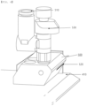
- FIG. 2 is a perspective view of an electrode cutting apparatus including a separated foreign matter removal unit according to an embodiment of the present invention.
- the electrode cutting apparatus may include an upper unit 100 including an upper cutter 110 disposed above an electrode sheet; a lower unit 200 including a lower cutter 210 disposed under the electrode sheet; a guide portion 300 configured to guide upward and downward movement of the upper unit; a gripper 400 configured to face the electrode sheet, which is supplied between the upper cutter, which performs upward and downward reciprocation, and the lower cutter, which is stationary, in parallel therewith, the gripper being configured to fix the electrode sheet; an upper gripper 410; and a blow unit 500 located at the upper gripper 410, the blow unit being configured to remove foreign matter generated when the electrode sheet is cut.
- the upper unit may include an upper cutter configured to cut the electrode sheet, an upper holder to which the upper cutter is fixed, and an upper frame to which the upper holder is mounted.
- the upper cutter may be configured to have a double-edged structure in which a central portion of the upper cutter is short and opposite ends of the upper cutter are long.
- the lower part of the upper cutter may have a curved arch shape when viewed in plan view or a bent polygonal structure when viewed in plan view.
- the lower unit may include a lower cutter configured to cut the electrode sheet and a lower frame to which the lower cutter is fixed.
- a moving unit 130 configured to transmit power to the upper unit may be further included.
- the moving unit performs a function of transmitting power necessary for upward and downward movement of the upper frame and a function of preventing occurrence of tolerance in clearance between the upper cutter and the lower cutter.
- the electrode sheet is cut in the state in which the clearance between the upper cutter and the lower cutter is accurately adjusted. As the number of cuttings is increased, tolerance occurs in the adjusted clearance between the upper cutter and the lower cutter, and the tolerance may deviate from a permitted limit.
- the moving unit is further disposed at a central portion of the upper frame in order to guarantee straightness in upward and downward movement of the upper cutter, whereby distortion of the upper cutter may be prevented, and therefore uniform force of cutting the electrode sheet may be maintained.
- the gripper includes a pair of an upper gripper and a lower gripper disposed respectively at the upper surface and the lower surface of the electrode sheet.
- the clearance between the upper gripper and the lower gripper may be reduced so as to grip the electrode sheet.
- the clearance between the upper gripper and the lower gripper may be adjusted in the state in which the upper gripper and the lower gripper are spaced apart from each other such that cutting and feeding of the electrode sheet are continuously performed.
- the electrode sheet may be disposed between the upper unit and the lower unit, and the upper cutter may be downwardly moved so as to be adjacent to the front surface of the lower cutter in order to cut the electrode sheet.
- a main body of the electrode cutting apparatus is synchronized with feeding speed of the electrode sheet and is moved in a feeding direction of the electrode sheet.
- the upper unit is moved upwards and downwards to cut the electrode sheet.
- the upper unit 100 is disposed above an electrode sheet 1 for cutting
- the lower unit 200 is disposed under the electrode sheet for cutting
- the guide portion 300 performs a function of guiding upward and downward movement of the upper unit 100.
- the upper unit 100 includes an upper cutter 110 configured to cut the electrode sheet, an upper holder 120 to which the upper cutter 110 is fixed, and an upper frame (not shown) to which the upper holder 120 is mounted.
- the lower unit 200 includes a lower cutter 210 configured to cut the electrode sheet and a lower frame 220 to which the lower cutter 210 is fixed.
- the electrode sheet is disposed between the upper unit 100 and the lower unit 200.
- the upper cutter 110 may be downwardly moved so as to be adjacent to the front surface of the lower cutter 210 in order to cut the electrode sheet.
- the clearance may be 0.
- the electrode cutting apparatus may include a lower gripper 420, and a suction unit 600 located at the lower unit and the lower gripper 420.
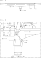
- FIG. 3 is a front view and a perspective view of a suction blow valve unit according to an embodiment of the present invention.
- the suction blow valve unit may include a valve blow fitting portion 710 connected to the blow unit and a valve suction fitting portion 720 connected to the suction unit.
- the suction blow valve unit may include a suction blow valve 730 movable upwards and downwards, the suction blow valve being configured to serve as valves of a suction fitting portion 640 of the suction unit and the valve suction fitting portion 720 of the suction blow valve unit simultaneously with cross between the upper cutter and the lower cutter or at a predetermined time after cross between the upper cutter and the lower cutter.
- the rectangular suction blow valve may be coupled to a rectangular suction blow valve plate 740, and may serve as the valves of the suction fitting portion 640 of the suction unit and the valve suction fitting portion 720 of the suction blow valve unit while being moved upwards and downwards along a suction blow valve rail 750 formed on the suction blow valve plate.
- the suction blow valve itself may serve as a vacuum pressure valve between the suction fitting portion and the valve suction fitting portion.
- the valve when the suction blow valve is moved upwards, the valve may be closed, and, when the suction blow valve is moved downwards, the valve may be opened.
- the upward and downward movement of the suction blow valve may be inversely configured as long as opening and closing of the valve are performed.
- a suction blow valve unit 700 may be formed at one side of the upper unit.
- the suction blow valve unit may be configured such that an air pressure valve (not shown) connected via a blow fitting portion 510 of the blow unit and the valve blow fitting portion 710 is opened only when the upper cutter is moved downwards.
- a fluid, preferably air, necessary to blow foreign matter generated at the electrode cutting apparatus may be supplied from the suction blow valve unit.
- Vacuum pressure necessary to remove separated foreign matter generated at the electrode cutting apparatus by suctioning may be supplied from the suction blow valve unit.
- the suction blow valve unit is a switching structure configured to connect the blow unit and/or the suction unit for supply of main air pressure and removal of foreign matter in response to operation of the electrode cutting apparatus.
- the suction blow valve unit controls air and vacuum pressure necessary for the blow unit and/or the suction unit in a state of being interlocked with upward and downward reciprocation of the upper cutter formed at the upper unit.
- FIG. 4 is a perspective view of a blow unit according to an embodiment of the present invention.
- the blow unit may be provided with an injection nozzle 520, and the injection nozzle may be located so as to face the portion at which the upper cutter and the lower cutter cross in the state in which the electrode sheet is interposed therebetween.
- the blow unit is formed at each of opposite ends of the upper surface of the upper gripper so as to correspond to the upper cutter.
- the injection nozzle may have a downward angle ⁇ of greater than 0 degrees to less than 90 degrees relative to a horizontal plane.
- the downward angle of the injection nozzle is preferably 10 degrees to 60 degrees, more preferably 20 degrees to 45 degrees.
- the downward angle of the injection nozzle may be 30 degrees. If the downward angle of the injection nozzle deviates from the above range, foreign matter may not be smoothly separated.
- FIG. 5 is a perspective view of a suction unit according to an embodiment of the present invention.
- the suction unit may have a section that is gradually narrowed from the upper part to the lower part thereof, and the width of an upper suction portion 610 that faces the lower cutter may be formed so as to correspond to the width of the lower cutter.
- the upper suction portion may have a shape in which the width of the upper suction portion is gradually narrowed from the surface thereof corresponding to the lower cutter.
- the shape is an inverted equilateral triangle ( ⁇ ).
- FIG. 6 is a detailed perspective view of the electrode cutting apparatus to which the blow unit and the suction unit according to the embodiments of the present invention are applied.
- the surface of the upper suction portion that faces the lower cutter may be provided with a plurality of suction holes 620. Foreign matter separated by the blow unit may be introduced into the suction holes, whereby the foreign matter may be removed.
- FIG. 7 is a photograph showing capture of foreign matter generated when the separated foreign matter removal unit according to the embodiment of the present invention is operated and stopped.
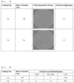
- FIG. 8 is a table showing a comparison in particle size distribution of foreign matter generated when the separated foreign matter removal unit according to the embodiment of the present invention is operated and stopped.
- the largest size of foreign matter captured when the separated foreign matter removal unit of the electrode cutting apparatus was operated was 714 um, and the largest size of metallic foreign matter was 297 ⁇ m.
- the largest size of foreign matter captured when the separated foreign matter removal unit of the electrode cutting apparatus was not operated was 861 um, and the largest size of metallic foreign matter was 634 ⁇ m.
Landscapes
- Engineering & Computer Science (AREA)
- Life Sciences & Earth Sciences (AREA)
- Forests & Forestry (AREA)
- Mechanical Engineering (AREA)
- Manufacturing & Machinery (AREA)
- Chemical & Material Sciences (AREA)
- Chemical Kinetics & Catalysis (AREA)
- Electrochemistry (AREA)
- General Chemical & Material Sciences (AREA)
- Battery Electrode And Active Subsutance (AREA)
Abstract
Description
- This application claims the benefit of priority to
Korean Patent Application No. 2020-0109630 filed on August 28, 2020 - The present invention relates to an electrode cutting apparatus including a separated foreign matter removal unit, and more particularly to an electrode cutting apparatus including a separated foreign matter removal unit capable of immediately removing separated foreign matter generated at the time of electrode cutting through a blow unit and a suction unit configured to be repeatedly operated and stopped according to an electrode cutting operation in order to remove separated foreign matter generated when the electrode cutting apparatus performs electrode cutting.
- A lithium secondary battery, which is capable of being charged and discharged, has been widely used as an energy source for wireless mobile devices or wearable devices, which are worn on bodies, and has also been used as an energy source for electric vehicles and hybrid electric vehicles presented as alternatives to existing gasoline and diesel vehicles, which cause air pollution.
- The lithium secondary battery includes an electrode assembly including a stack of a positive electrode plate coated with a positive electrode active material, a negative electrode plate coated with a negative electrode active material, and a separator located between the positive electrode plate and the negative electrode plate, the separator being configured to prevent short circuit, the separator being configured such that lithium ions (Li-ion) are movable therethrough, a battery case configured to receive the electrode assembly, and an electrolytic solution injected into the battery case such that the lithium ions are movable.
- In general, the positive electrode plate and the negative electrode plate may be manufactured through a process of coating a long sheet type positive electrode sheet and a long sheet type negative electrode sheet with a positive electrode active material and a negative electrode active material, respectively, drying and rolling the active materials, and cutting the positive electrode sheet and the negative electrode sheet to a predetermined size to manufacture unit electrodes.
- A conventional electrode plate cutting apparatus configured to manufacture the unit electrodes includes a feeding unit configured to feed an electrode plate in a state of being seated and a cutter installed at one side of the feeding unit. The cutter is divided into an upper cutter and a lower cutter. Specifically, based on the electrode plate, the lower cutter is fixed to the lower side of the electrode plate while the upper cutter is installed at the upper side of the electrode plate, and the upper cutter is moved upwards and downwards at an electrode plate cutting position. When the electrode plate is fed to the cutting apparatus, therefore, the edge of the upper cutter and the edge of the lower cutter come into contact with each other to cut the electrode plate.
- As a result of repetitive cross contact between the upper cutter and the lower cutter, however, foreign matter is generated, the edges of the cutters are worn, and the edges of the cutters are curved, whereby the electrode plate is cut in the state in which a cut section is not smooth or a burr is generated.
- As the cutting process using the upper cutter and the lower cutter is repeatedly performed, foreign matter is continuously separated from the electrode sheet.
- In connection therewith,
FIG. 1 is a view showing operation of a conventional electrode cutting apparatus including no separated foreign matter removal unit. - Referring to (a) of
FIG. 1 , there are shown anupper cutter 110 configured to reciprocate upwards and downwards in order to cut an electrode sheet and a stationarylower cutter 210 configured to cut the electrode sheet that enters between the lower cutter and the upper cutter. - There is also shown a
gripper 400 configured to face the electrode sheet, which is supplied between the upper cutter, which performs upward and downward reciprocation, and the lower cutter, which is stationary, in parallel therewith, the gripper being configured to fix the electrode sheet. - There are also shown an
upper gripper 410 formed so as to face the upper cutter in parallel therewith and alower gripper 420 formed so as to face the lower cutter in parallel therewith. The upper gripper and the lower gripper may fix the electrode sheet. - Referring to (b) of
FIG. 1 , when the upper cutter cuts the electrode sheet while moving downwards, foreign matter may be generated from a cut portion of the electrode sheet. - Referring to (c) of
FIG. 1 , when the upper cutter moves upwards after cutting the electrode sheet, the foreign matter may be separated from the cut portion of the electrode sheet. - Patent Document 1 discloses a separator cutting apparatus for secondary batteries configured to cut a raw material for separators, the separator cutting apparatus including a cutting unit configured to cut the raw material for separators along a predetermined cutting line, wherein the cutting unit includes a cutter member having a first cutter end and a second cutter end, and a cleaner member configured to remove contaminants generated when the raw material for separators is cut. However, the construction of a separated foreign matter removal unit provided at an electrode cutting apparatus including an upper cutter and a lower cutter is not disclosed.
-
Patent Document 2 discloses an electrode production system including upper and lower mold fixing plates and a dust collection nozzle configured to suction foreign matter, wherein the upper and lower mold fixing plates are moved through a crank shaft. However, the construction of a separated foreign matter removal unit including an electrode sheet gripper and a blow unit provided at an electrode cutting apparatus including an upper cutter and a lower cutter is not disclosed. - Therefore, there is a need to develop an electrode cutting apparatus including a separated foreign matter removal unit configured to easily remove foreign matter generated from an electrode sheet cut through upward and downward reciprocation of an upper cutter and a lower cutter through blowing and suction and to be repeatedly operated and stopped in a state of being interlocked with upward and downward reciprocation of the cutters in order to effectively remove the separated foreign matter.
-
- (Patent Document 1)
Korean Registered Patent Publication No. 1893706 - (Patent Document 2)
Korean Registered Patent Publication No. 1475703 - The present invention has been made in view of the above problems, and it is an object of the present invention to provide an electrode cutting apparatus including a separated foreign matter removal unit capable of immediately removing separated foreign matter generated at the time of electrode cutting through a blow unit and a suction unit configured to be repeatedly operated and stopped according to an electrode cutting operation in order to remove separated foreign matter generated when the electrode cutting apparatus, which includes an upper cutter, performs electrode cutting.
- In order to accomplish the above object, an electrode cutting apparatus according to the present invention includes an upper unit (100) including an upper cutter (110) disposed above an electrode sheet; a lower unit (200) including a lower cutter (210) disposed under the electrode sheet; a gripper (400) configured to face the electrode sheet supplied between the upper cutter, which is configured to perform upward and downward reciprocation, and the lower cutter, which is configured to remain stationary, the lower cutter being in parallel with the upper cutter, the gripper being configured to fix the electrode sheet; an upper gripper (410); and a blow unit (500) located at the upper gripper (410), the blow unit configured to remove foreign matter generated when the supplied electrode sheet is cut.
- The electrode cutting apparatus may further include a lower gripper (420) and a suction unit located at the lower unit and the lower gripper (420).
- The electrode cutting apparatus may further include a suction blow valve unit (700) formed at one side of the upper unit, the suction blow valve unit configured such that an air pressure valve (not shown) connected via a blow fitting portion (510) of the blow unit and a valve blow fitting portion (710) is opened only when the upper cutter is moved downwards.
- The blow unit may be provided with an injection nozzle (520), and the injection nozzle may be located so as to face the portion at which the upper cutter and the lower cutter cross in the state in which the electrode sheet is interposed between the upper cutter and the lower cutter.
- The injection nozzle may have a downward angle of greater than 0 degrees to less than 90 degrees relative to a horizontal plane.
- The suction unit may have a section that is gradually narrowed from the upper part to the lower part thereof, the width of an upper suction portion (610) that faces the lower cutter may be formed so as to correspond to the width of the lower cutter, and the width of the upper suction portion may be gradually narrowed from the surface thereof corresponding to the lower cutter.
- The surface of the upper suction portion that faces the lower cutter may define a plurality of suction holes (620).
- The suction unit may be provided in a side surface thereof adjacent to the upper suction portion with a plurality of vacuum prevention holes (630).
- A suction fitting portion (640) of the suction unit and a valve suction fitting portion (720) of the suction blow valve unit may be operated through upward and downward movement of the suction blow valve (730) simultaneously with a cross between the upper cutter and the lower cutter or at a predetermined time after the cross between the upper cutter and the lower cutter.
- The blow unit may be provided at one side thereof with an injection adjustment portion (530) configured to adjust the injection flow rate and/or the number of injections of the injection nozzle.
- As is apparent from the above description, an electrode cutting apparatus including a separated foreign matter removal unit according to the present invention is configured such that the separated foreign matter removal unit is operated and stopped in a state of being interlocked with upward and downward reciprocation of an upper cutter and a lower cutter, whereby it is possible to continuously remove separated foreign matter.
- In addition, the separated foreign matter removal unit is further assembled to a main body of the electrode cutting apparatus, whereby it is possible to accurately and easily remove separated foreign matter without being affected by adjustment of clearance and parallelism between the upper cutter and the lower cutter.
- In addition, the separated foreign matter removal unit is mounted to the main body so as to be interlocked with operation of the upper cutter and the lower cutter, whereby it is possible to manage electrodes cut so as to have consistent quality.
- In addition, it is possible to effectively remove foreign matter having an electrode mixture layer separated from the cut surface of an electrode cut using the electrode cutting apparatus including the separated foreign matter removal unit according to the present invention, whereby it is possible to reduce an electrode defect rate and to increase electrode production speed.
-
-
FIG. 1 is a conceptual view showing that separated foreign matter is generated at a conventional electrode cutting apparatus. -
FIG. 2 is a perspective view of an electrode cutting apparatus including a separated foreign matter removal unit according to an embodiment of the present invention. -
FIG. 3 is a front view and a perspective view of a suction blow valve unit according to an embodiment of the present invention. -
FIG. 4 is a perspective view of a blow unit according to an embodiment of the present invention. -
FIG. 5 is a perspective view of a suction unit according to an embodiment of the present invention. -
FIG. 6 is a detailed perspective view of the electrode cutting apparatus to which the blow unit and the suction unit according to the embodiments of the present invention are applied. -
FIG. 7 is a photograph showing capture of foreign matter generated when the separated foreign matter removal unit according to the embodiment of the present invention is operated and stopped. -
FIG. 8 is a table showing comparison in particle size distribution of foreign matter generated when the separated foreign matter removal unit according to the embodiment of the present invention is operated and stopped. - Now, preferred embodiments of the present invention will be described in detail with reference to the accompanying drawings such that the preferred embodiments of the present invention can be easily implemented by a person having ordinary skill in the art to which the present invention pertains. In describing the principle of operation of the preferred embodiments of the present invention in detail, however, a detailed description of known functions and configurations incorporated herein will be omitted when the same may obscure the subject matter of the present invention.
- In addition, the same reference numbers will be used throughout the drawings to refer to parts that perform similar functions or operations. In the case in which one part is said to be connected to another part throughout the specification, not only may the one part be directly connected to the other part, but also, the one part may be indirectly connected to the other part via a further part. In addition, that a certain element is included does not mean that other elements are excluded, but means that such elements may be further included unless mentioned otherwise.
- In addition, a description to embody elements through limitation or addition may be applied to all inventions, unless particularly restricted, and does not limit a specific invention.
- Also, in the description of the invention and the claims of the present application, singular forms are intended to include plural forms unless mentioned otherwise.
- Also, in the description of the invention and the claims of the present application, "or" includes "and" unless mentioned otherwise. Therefore, "including A or B" means three cases, namely, the case including A, the case including B, and the case including A and B.
- In addition, all numeric ranges include the lowest value, the highest value, and all intermediate values therebetween unless the context clearly indicates otherwise.
- Embodiments of the present invention will be described in detail with reference to the accompanying drawings.
-
FIG. 2 is a perspective view of an electrode cutting apparatus including a separated foreign matter removal unit according to an embodiment of the present invention. - The electrode cutting apparatus may include an
upper unit 100 including anupper cutter 110 disposed above an electrode sheet; alower unit 200 including alower cutter 210 disposed under the electrode sheet; aguide portion 300 configured to guide upward and downward movement of the upper unit; agripper 400 configured to face the electrode sheet, which is supplied between the upper cutter, which performs upward and downward reciprocation, and the lower cutter, which is stationary, in parallel therewith, the gripper being configured to fix the electrode sheet; anupper gripper 410; and ablow unit 500 located at theupper gripper 410, the blow unit being configured to remove foreign matter generated when the electrode sheet is cut. - The upper unit may include an upper cutter configured to cut the electrode sheet, an upper holder to which the upper cutter is fixed, and an upper frame to which the upper holder is mounted.
- The upper cutter may be configured to have a double-edged structure in which a central portion of the upper cutter is short and opposite ends of the upper cutter are long. For example, the lower part of the upper cutter may have a curved arch shape when viewed in plan view or a bent polygonal structure when viewed in plan view.
- The lower unit may include a lower cutter configured to cut the electrode sheet and a lower frame to which the lower cutter is fixed.
- A moving
unit 130 configured to transmit power to the upper unit may be further included. - The moving unit performs a function of transmitting power necessary for upward and downward movement of the upper frame and a function of preventing occurrence of tolerance in clearance between the upper cutter and the lower cutter.
- Specifically, the electrode sheet is cut in the state in which the clearance between the upper cutter and the lower cutter is accurately adjusted. As the number of cuttings is increased, tolerance occurs in the adjusted clearance between the upper cutter and the lower cutter, and the tolerance may deviate from a permitted limit.
- In the present invention, as described above, the moving unit is further disposed at a central portion of the upper frame in order to guarantee straightness in upward and downward movement of the upper cutter, whereby distortion of the upper cutter may be prevented, and therefore uniform force of cutting the electrode sheet may be maintained.
- The gripper includes a pair of an upper gripper and a lower gripper disposed respectively at the upper surface and the lower surface of the electrode sheet.
- The clearance between the upper gripper and the lower gripper may be reduced so as to grip the electrode sheet. Alternatively, the clearance between the upper gripper and the lower gripper may be adjusted in the state in which the upper gripper and the lower gripper are spaced apart from each other such that cutting and feeding of the electrode sheet are continuously performed.
- In the electrode cutting apparatus according to the present invention, the electrode sheet may be disposed between the upper unit and the lower unit, and the upper cutter may be downwardly moved so as to be adjacent to the front surface of the lower cutter in order to cut the electrode sheet.
- When the electrode sheet is fed by a feeding roller, a main body of the electrode cutting apparatus is synchronized with feeding speed of the electrode sheet and is moved in a feeding direction of the electrode sheet. When relative speed between the main body and the electrode sheet in the feeding direction becomes 0, the upper unit is moved upwards and downwards to cut the electrode sheet.
- Subsequently, when the main body of the electrode cutting apparatus returns to a work start position, 1 cycle is completed, and the electrode sheet is cut while the cycle is repeated.
- Subsequently, when the main body of the electrode cutting apparatus returns to a work start position, 1 cycle is completed, and the electrode sheet is cut while the cycle is repeated.
- The
upper unit 100 is disposed above an electrode sheet 1 for cutting, thelower unit 200 is disposed under the electrode sheet for cutting, and theguide portion 300 performs a function of guiding upward and downward movement of theupper unit 100. - The
upper unit 100 includes anupper cutter 110 configured to cut the electrode sheet, anupper holder 120 to which theupper cutter 110 is fixed, and an upper frame (not shown) to which theupper holder 120 is mounted. - The
lower unit 200 includes alower cutter 210 configured to cut the electrode sheet and alower frame 220 to which thelower cutter 210 is fixed. - The electrode sheet is disposed between the
upper unit 100 and thelower unit 200. Theupper cutter 110 may be downwardly moved so as to be adjacent to the front surface of thelower cutter 210 in order to cut the electrode sheet. - When the
upper cutter 110 is moved downwards, there may be formed no clearance between thelower cutter 210 and theupper cutter 110. Specifically, the clearance may be 0. - The electrode cutting apparatus may include a
lower gripper 420, and asuction unit 600 located at the lower unit and thelower gripper 420. -
FIG. 3 is a front view and a perspective view of a suction blow valve unit according to an embodiment of the present invention. - The suction blow valve unit may include a valve blow
fitting portion 710 connected to the blow unit and a valve suctionfitting portion 720 connected to the suction unit. - The suction blow valve unit may include a
suction blow valve 730 movable upwards and downwards, the suction blow valve being configured to serve as valves of a suctionfitting portion 640 of the suction unit and the valve suctionfitting portion 720 of the suction blow valve unit simultaneously with cross between the upper cutter and the lower cutter or at a predetermined time after cross between the upper cutter and the lower cutter. - The rectangular suction blow valve may be coupled to a rectangular suction
blow valve plate 740, and may serve as the valves of the suctionfitting portion 640 of the suction unit and the valve suctionfitting portion 720 of the suction blow valve unit while being moved upwards and downwards along a suctionblow valve rail 750 formed on the suction blow valve plate. - That is, the suction blow valve itself may serve as a vacuum pressure valve between the suction fitting portion and the valve suction fitting portion.
- In general, when the suction blow valve is moved upwards, the valve may be closed, and, when the suction blow valve is moved downwards, the valve may be opened. The upward and downward movement of the suction blow valve may be inversely configured as long as opening and closing of the valve are performed.
- A suction
blow valve unit 700 may be formed at one side of the upper unit. The suction blow valve unit may be configured such that an air pressure valve (not shown) connected via a blowfitting portion 510 of the blow unit and the valve blowfitting portion 710 is opened only when the upper cutter is moved downwards. - A fluid, preferably air, necessary to blow foreign matter generated at the electrode cutting apparatus may be supplied from the suction blow valve unit.
- Vacuum pressure necessary to remove separated foreign matter generated at the electrode cutting apparatus by suctioning may be supplied from the suction blow valve unit.
- The suction blow valve unit is a switching structure configured to connect the blow unit and/or the suction unit for supply of main air pressure and removal of foreign matter in response to operation of the electrode cutting apparatus.
- That is, the suction blow valve unit controls air and vacuum pressure necessary for the blow unit and/or the suction unit in a state of being interlocked with upward and downward reciprocation of the upper cutter formed at the upper unit.
-
FIG. 4 is a perspective view of a blow unit according to an embodiment of the present invention. - The blow unit may be provided with an
injection nozzle 520, and the injection nozzle may be located so as to face the portion at which the upper cutter and the lower cutter cross in the state in which the electrode sheet is interposed therebetween. - Preferably, the blow unit is formed at each of opposite ends of the upper surface of the upper gripper so as to correspond to the upper cutter.
- The injection nozzle may have a downward angle α of greater than 0 degrees to less than 90 degrees relative to a horizontal plane. The downward angle of the injection nozzle is preferably 10 degrees to 60 degrees, more preferably 20 degrees to 45 degrees. The downward angle of the injection nozzle may be 30 degrees. If the downward angle of the injection nozzle deviates from the above range, foreign matter may not be smoothly separated.
-
FIG. 5 is a perspective view of a suction unit according to an embodiment of the present invention. - The suction unit may have a section that is gradually narrowed from the upper part to the lower part thereof, and the width of an
upper suction portion 610 that faces the lower cutter may be formed so as to correspond to the width of the lower cutter. The upper suction portion may have a shape in which the width of the upper suction portion is gradually narrowed from the surface thereof corresponding to the lower cutter. - Preferably, the shape is an inverted equilateral triangle (∇).
-
FIG. 6 is a detailed perspective view of the electrode cutting apparatus to which the blow unit and the suction unit according to the embodiments of the present invention are applied. - The surface of the upper suction portion that faces the lower cutter may be provided with a plurality of suction holes 620. Foreign matter separated by the blow unit may be introduced into the suction holes, whereby the foreign matter may be removed.
- Experiments were performed using an electrode cutting apparatus including a separated foreign matter removal unit according to an embodiment of the present invention.
- Foreign matter generated while a supplied electrode sheet was cut 10,000 times using the electrode cutting apparatus including the separated foreign matter removal unit was captured and analyzed. As a comparative example, foreign matter generated while the electrode sheet was cut 10,000 times in the state in which the separated foreign matter removal unit was not operated was captured and analyzed.
- Foreign matter generated at the time of cutting was captured under the electrode cutting apparatus for comparison in amount of the foreign matter.
-
FIG. 7 is a photograph showing capture of foreign matter generated when the separated foreign matter removal unit according to the embodiment of the present invention is operated and stopped. - It can be seen from
FIG. 7 that the capture amounts of separated foreign matter were different from each other, as can be seen from photographs, and that the amount of foreign matter captured when the separated foreign matter removal unit was operated was reduced by about 50% or more. -
FIG. 8 is a table showing a comparison in particle size distribution of foreign matter generated when the separated foreign matter removal unit according to the embodiment of the present invention is operated and stopped. - As the result of analysis, the largest size of foreign matter captured when the separated foreign matter removal unit of the electrode cutting apparatus was operated was 714 um, and the largest size of metallic foreign matter was 297 µm.
- As the result of analysis, the largest size of foreign matter captured when the separated foreign matter removal unit of the electrode cutting apparatus was not operated was 861 um, and the largest size of metallic foreign matter was 634 µm.
- Those skilled in the art to which the present invention pertains will appreciate that various applications and modifications are possible within the category of the present invention based on the above description.
-
- 1:
- Electrode sheet
- 100:
- Upper unit
- 110:
- Upper cutter
- 120:
- Upper holder
- 200:
- Lower unit
- 210:
- Lower cutter
- 220:
- Lower frame
- 300:
- Guide portion
- 400:
- Gripper
- 410:
- Upper gripper
- 420:
- Lower gripper
- 500:
- Blow unit
- 510:
- Blow fitting portion
- 520:
- Injection nozzle
- 530:
- Injection adjustment portion
- 600:
- Suction unit
- 610:
- Upper suction portion
- 620:
- Suction hole
- 630:
- Vacuum prevention hole
- 640:
- Suction fitting portion
- 700:
- Suction blow valve unit
- 710:
- Valve blow fitting portion
- 720:
- Valve suction fitting portion
- 730:
- Suction blow valve
- 740:
- Suction blow valve plate
- 750:
- Suction blow valve rail
Claims (10)
- An electrode cutting apparatus comprising:an upper unit comprising an upper cutter disposed above an electrode sheet;a lower unit comprising a lower cutter disposed under the electrode sheet;a gripper configured to face the electrode sheet supplied between the upper cutter, which is configured to perform upward and downward reciprocation, and the lower cutter, which is configured to remain stationary, the lower cutter being in parallel with the upper cutter, the gripper being configured to fix the electrode sheet;an upper gripper; anda blow unit located at the upper gripper, the blow unit configured to remove foreign matter generated when the supplied electrode sheet is cut.
- The electrode cutting apparatus according to claim 1, further comprising a lower gripper; and a suction unit located at the lower unit and the lower gripper.
- The electrode cutting apparatus according to claim 1, further comprising a suction blow valve unit formed at one side of the upper unit, the suction blow valve unit configured such that a suction blow valve connected via a blow fitting portion of the blow unit and a valve blow fitting portion is opened only when the upper cutter is moved downwards.
- The electrode cutting apparatus according to claim 3, wherein the blow unit is provided with an injection nozzle, and
wherein the injection nozzle is located so as to face a portion at which the upper cutter and the lower cutter cross in a state in which the electrode sheet is interposed between the upper cutter and the lower cutter. - The electrode cutting apparatus according to claim 4, wherein the injection nozzle has a downward angle of greater than 0 degrees to less than 90 degrees relative to a horizontal plane.
- The electrode cutting apparatus according to claim 2, whereinthe suction unit has a section that is gradually narrowed from an upper part to a lower part thereof,a width of an upper suction portion that faces the lower cutter is formed so as to correspond to a width of the lower cutter, andthe width of the upper suction portion is gradually narrowed from a surface thereof corresponding to the lower cutter.
- The electrode cutting apparatus according to claim 6, wherein a surface of the upper suction portion that faces the lower cutter defines a plurality of suction holes.
- The electrode cutting apparatus according to claim 6, wherein the suction unit is provided in a side surface thereof adjacent to the upper suction portion with a plurality of vacuum prevention holes.
- The electrode cutting apparatus according to claim 3, wherein a suction fitting portion of the suction unit and a valve suction fitting portion of the suction blow valve unit are operated through upward and downward movement of the suction blow valve simultaneously with a cross between the upper cutter and the lower cutter or at a predetermined time after the cross between the upper cutter and the lower cutter.
- The electrode cutting apparatus according to claim 3, wherein the blow unit is provided at one side thereof with an injection adjustment portion configured to adjust an injection flow rate and/or a number of injections of the injection nozzle.
Applications Claiming Priority (2)
| Application Number | Priority Date | Filing Date | Title |
|---|---|---|---|
| KR1020200109630A KR20220028521A (en) | 2020-08-28 | 2020-08-28 | Electrode Cutting Device Including Separated Foreign Materials Removal Unit |
| PCT/KR2021/011514 WO2022045828A1 (en) | 2020-08-28 | 2021-08-27 | Electrode cutting apparatus including detached foreign substance removing unit |
Publications (3)
| Publication Number | Publication Date |
|---|---|
| EP4205926A1 true EP4205926A1 (en) | 2023-07-05 |
| EP4205926A4 EP4205926A4 (en) | 2024-03-13 |
| EP4205926B1 EP4205926B1 (en) | 2025-10-15 |
Family
ID=80355518
Family Applications (1)
| Application Number | Title | Priority Date | Filing Date |
|---|---|---|---|
| EP21862124.1A Active EP4205926B1 (en) | 2020-08-28 | 2021-08-27 | Electrode cutting apparatus including detached foreign substance removing unit |
Country Status (6)
| Country | Link |
|---|---|
| US (1) | US20230249374A1 (en) |
| EP (1) | EP4205926B1 (en) |
| KR (2) | KR20220028521A (en) |
| CN (1) | CN115768609A (en) |
| ES (1) | ES3058714T3 (en) |
| WO (1) | WO2022045828A1 (en) |
Families Citing this family (4)
| Publication number | Priority date | Publication date | Assignee | Title |
|---|---|---|---|---|
| EP4241942B1 (en) * | 2022-01-28 | 2025-07-23 | Contemporary Amperex Technology (Hong Kong) Limited | Blade driving apparatus and cutting device |
| KR102469560B1 (en) | 2022-08-31 | 2022-11-22 | 주식회사 유진테크놀로지 | Cutting device for secondary battery electrode |
| KR102497010B1 (en) | 2022-10-27 | 2023-02-07 | 주식회사 유진테크놀로지 | Electrode cutting device for secondary battery with top cutter and bottom cutter modularized |
| CN120359110A (en) * | 2023-09-08 | 2025-07-22 | 株式会社Lg新能源 | Electrode cutter capable of preventing electrode from being separated |
Family Cites Families (15)
| Publication number | Priority date | Publication date | Assignee | Title |
|---|---|---|---|---|
| JP2003025136A (en) * | 2001-07-17 | 2003-01-29 | Sony Corp | Electrode cutting device |
| JP4329665B2 (en) * | 2004-09-27 | 2009-09-09 | コニカミノルタビジネステクノロジーズ株式会社 | Paper cutting device, paper post-processing device, and image forming system |
| JP5327940B2 (en) * | 2008-02-14 | 2013-10-30 | 三菱レイヨン株式会社 | Continuous sheet cutting apparatus and method |
| CN101879050A (en) * | 2009-05-06 | 2010-11-10 | 乐金电子(天津)电器有限公司 | Slit brush head with valve blocks for dust collector |
| CN102028433A (en) * | 2009-09-29 | 2011-04-27 | 乐金电子(天津)电器有限公司 | Slip brush head of dust collector |
| KR101115299B1 (en) * | 2011-06-13 | 2012-03-13 | (주)엘케이이노베이션 | Electrode cutting apparatus for secondary battery |
| KR101337226B1 (en) * | 2012-03-09 | 2013-12-05 | 유일에너테크(주) | Cutting apparatus for electrodes of battery |
| KR101475703B1 (en) | 2013-12-04 | 2014-12-23 | (주)이피씨코리아 | Machine for tube expander auto cutting |
| KR101739168B1 (en) * | 2014-05-30 | 2017-05-23 | 주식회사 엘지화학 | Electrode cutter |
| KR101893706B1 (en) | 2017-12-15 | 2018-08-30 | 이진수 | Separator film for secondary battery cutting apparatus |
| KR102293007B1 (en) * | 2018-10-05 | 2021-08-24 | 주식회사 엘지에너지솔루션 | Apparatus for attaching tape to battery cell |
| KR102293364B1 (en) | 2019-03-13 | 2021-08-23 | 방만혁 | Apparatus and methods for coupling pipes |
| KR102120654B1 (en) * | 2019-04-03 | 2020-06-09 | 송석화 | Equipment for finishing a cutting plane of corrugated tube |
| JP6716756B1 (en) * | 2019-06-13 | 2020-07-01 | Dmg森精機株式会社 | Machine Tools |
| CN210650722U (en) * | 2019-08-19 | 2020-06-02 | 浙江大学 | Adsorber |
-
2020
- 2020-08-28 KR KR1020200109630A patent/KR20220028521A/en not_active Ceased
-
2021
- 2021-08-27 ES ES21862124T patent/ES3058714T3/en active Active
- 2021-08-27 US US18/003,740 patent/US20230249374A1/en active Pending
- 2021-08-27 CN CN202180042904.9A patent/CN115768609A/en active Pending
- 2021-08-27 EP EP21862124.1A patent/EP4205926B1/en active Active
- 2021-08-27 WO PCT/KR2021/011514 patent/WO2022045828A1/en not_active Ceased
-
2024
- 2024-10-11 KR KR1020240138105A patent/KR20240153947A/en active Pending
Also Published As
| Publication number | Publication date |
|---|---|
| US20230249374A1 (en) | 2023-08-10 |
| CN115768609A (en) | 2023-03-07 |
| KR20220028521A (en) | 2022-03-08 |
| EP4205926A4 (en) | 2024-03-13 |
| WO2022045828A1 (en) | 2022-03-03 |
| ES3058714T3 (en) | 2026-03-12 |
| EP4205926B1 (en) | 2025-10-15 |
| KR20240153947A (en) | 2024-10-24 |
Similar Documents
| Publication | Publication Date | Title |
|---|---|---|
| EP4205926B1 (en) | Electrode cutting apparatus including detached foreign substance removing unit | |
| EP4186661B1 (en) | Cartridge-type electrode cutting device | |
| KR102189942B1 (en) | Notching mold for secondary battery having improved punch mounting structure | |
| US12539636B2 (en) | Power transmission unit for electrode cutting apparatuses | |
| KR101813249B1 (en) | Apparatus for cutting jelly roll tab of lithium secondary battery | |
| KR101774262B1 (en) | Electrode Tab Fabricating Apparatus with Improved Dimensional Stability and Method for Fabricating Electrode Tab Utilizing the Same | |
| KR20220164920A (en) | Battery dismantling device | |
| KR20230109896A (en) | Electrode tab notching device | |
| CN116075404B (en) | Electrode substrate notching apparatus and method | |
| JP2023535844A (en) | Electrode plate forming method and equipment | |
| US20230150784A1 (en) | Electrode Connection Apparatus and Electrode Connection Automation Method Using the Same | |
| CN223181178U (en) | Lamination unit processing device and lamination equipment | |
| KR102670131B1 (en) | Cutting device for electrode sheet | |
| DE102017216149A1 (en) | Method and device for producing an electrode stack for a battery cell | |
| CN219703627U (en) | Cutter assembly, cut-parts device and cut-parts machine | |
| EP4023402A1 (en) | Notching apparatus | |
| JP2002126828A (en) | Die for electrode plate cutting | |
| JP2003025136A (en) | Electrode cutting device | |
| KR20220101886A (en) | System for producing electrodes of battery | |
| US20230318007A1 (en) | Cutting Device, and Lamination Apparatus and Lamination Method for Secondary Battery Comprising the Same | |
| CN219235398U (en) | Pole piece cutting device | |
| CN217729001U (en) | Pole piece forming device | |
| CN119497658A (en) | Device for collecting foreign matter generated during laser grooving and method for collecting foreign matter using the same | |
| KR102461510B1 (en) | System for producing electrodes of battery | |
| EP4425592A1 (en) | Electrode production system for secondary battery |
Legal Events
| Date | Code | Title | Description |
|---|---|---|---|
| STAA | Information on the status of an ep patent application or granted ep patent |
Free format text: STATUS: THE INTERNATIONAL PUBLICATION HAS BEEN MADE |
|
| PUAI | Public reference made under article 153(3) epc to a published international application that has entered the european phase |
Free format text: ORIGINAL CODE: 0009012 |
|
| STAA | Information on the status of an ep patent application or granted ep patent |
Free format text: STATUS: REQUEST FOR EXAMINATION WAS MADE |
|
| 17P | Request for examination filed |
Effective date: 20221223 |
|
| AK | Designated contracting states |
Kind code of ref document: A1 Designated state(s): AL AT BE BG CH CY CZ DE DK EE ES FI FR GB GR HR HU IE IS IT LI LT LU LV MC MK MT NL NO PL PT RO RS SE SI SK SM TR |
|
| DAV | Request for validation of the european patent (deleted) | ||
| DAX | Request for extension of the european patent (deleted) | ||
| A4 | Supplementary search report drawn up and despatched |
Effective date: 20240209 |
|
| RIC1 | Information provided on ipc code assigned before grant |
Ipc: B26D 7/06 20060101ALI20240205BHEP Ipc: H01M 4/04 20060101ALI20240205BHEP Ipc: B26D 5/02 20060101ALI20240205BHEP Ipc: B26D 7/02 20060101ALI20240205BHEP Ipc: B26D 1/60 20060101ALI20240205BHEP Ipc: B26D 7/18 20060101AFI20240205BHEP |
|
| GRAP | Despatch of communication of intention to grant a patent |
Free format text: ORIGINAL CODE: EPIDOSNIGR1 |
|
| STAA | Information on the status of an ep patent application or granted ep patent |
Free format text: STATUS: GRANT OF PATENT IS INTENDED |
|
| INTG | Intention to grant announced |
Effective date: 20250710 |
|
| GRAS | Grant fee paid |
Free format text: ORIGINAL CODE: EPIDOSNIGR3 |
|
| GRAA | (expected) grant |
Free format text: ORIGINAL CODE: 0009210 |
|
| STAA | Information on the status of an ep patent application or granted ep patent |
Free format text: STATUS: THE PATENT HAS BEEN GRANTED |
|
| AK | Designated contracting states |
Kind code of ref document: B1 Designated state(s): AL AT BE BG CH CY CZ DE DK EE ES FI FR GB GR HR HU IE IS IT LI LT LU LV MC MK MT NL NO PL PT RO RS SE SI SK SM TR |
|
| REG | Reference to a national code |
Ref country code: GB Ref legal event code: FG4D Ref country code: CH Ref legal event code: F10 Free format text: ST27 STATUS EVENT CODE: U-0-0-F10-F00 (AS PROVIDED BY THE NATIONAL OFFICE) Effective date: 20251015 |
|
| REG | Reference to a national code |
Ref country code: DE Ref legal event code: R096 Ref document number: 602021040609 Country of ref document: DE |
|
| P01 | Opt-out of the competence of the unified patent court (upc) registered |
Free format text: CASE NUMBER: UPC_APP_8253_4205926/2025 Effective date: 20250929 |
|
| REG | Reference to a national code |
Ref country code: IE Ref legal event code: FG4D |
|
| REG | Reference to a national code |
Ref country code: NL Ref legal event code: MP Effective date: 20251015 |
|
| REG | Reference to a national code |
Ref country code: ES Ref legal event code: FG2A Ref document number: 3058714 Country of ref document: ES Kind code of ref document: T3 Effective date: 20260312 |
|
| REG | Reference to a national code |
Ref country code: AT Ref legal event code: MK05 Ref document number: 1846578 Country of ref document: AT Kind code of ref document: T Effective date: 20251015 |
|
| PG25 | Lapsed in a contracting state [announced via postgrant information from national office to epo] |
Ref country code: NL Free format text: LAPSE BECAUSE OF FAILURE TO SUBMIT A TRANSLATION OF THE DESCRIPTION OR TO PAY THE FEE WITHIN THE PRESCRIBED TIME-LIMIT Effective date: 20251015 |
|
| REG | Reference to a national code |
Ref country code: LT Ref legal event code: MG9D |
|
| PG25 | Lapsed in a contracting state [announced via postgrant information from national office to epo] |
Ref country code: NO Free format text: LAPSE BECAUSE OF FAILURE TO SUBMIT A TRANSLATION OF THE DESCRIPTION OR TO PAY THE FEE WITHIN THE PRESCRIBED TIME-LIMIT Effective date: 20260115 |
|
| PG25 | Lapsed in a contracting state [announced via postgrant information from national office to epo] |
Ref country code: HR Free format text: LAPSE BECAUSE OF FAILURE TO SUBMIT A TRANSLATION OF THE DESCRIPTION OR TO PAY THE FEE WITHIN THE PRESCRIBED TIME-LIMIT Effective date: 20251015 Ref country code: AT Free format text: LAPSE BECAUSE OF FAILURE TO SUBMIT A TRANSLATION OF THE DESCRIPTION OR TO PAY THE FEE WITHIN THE PRESCRIBED TIME-LIMIT Effective date: 20251015 Ref country code: FI Free format text: LAPSE BECAUSE OF FAILURE TO SUBMIT A TRANSLATION OF THE DESCRIPTION OR TO PAY THE FEE WITHIN THE PRESCRIBED TIME-LIMIT Effective date: 20251015 |
|
| PG25 | Lapsed in a contracting state [announced via postgrant information from national office to epo] |
Ref country code: RS Free format text: LAPSE BECAUSE OF FAILURE TO SUBMIT A TRANSLATION OF THE DESCRIPTION OR TO PAY THE FEE WITHIN THE PRESCRIBED TIME-LIMIT Effective date: 20260115 |
|
| PG25 | Lapsed in a contracting state [announced via postgrant information from national office to epo] |
Ref country code: IS Free format text: LAPSE BECAUSE OF FAILURE TO SUBMIT A TRANSLATION OF THE DESCRIPTION OR TO PAY THE FEE WITHIN THE PRESCRIBED TIME-LIMIT Effective date: 20260215 |
|
| PG25 | Lapsed in a contracting state [announced via postgrant information from national office to epo] |
Ref country code: PT Free format text: LAPSE BECAUSE OF FAILURE TO SUBMIT A TRANSLATION OF THE DESCRIPTION OR TO PAY THE FEE WITHIN THE PRESCRIBED TIME-LIMIT Effective date: 20260216 |
|
| PG25 | Lapsed in a contracting state [announced via postgrant information from national office to epo] |
Ref country code: PL Free format text: LAPSE BECAUSE OF FAILURE TO SUBMIT A TRANSLATION OF THE DESCRIPTION OR TO PAY THE FEE WITHIN THE PRESCRIBED TIME-LIMIT Effective date: 20251015 |
|
| PG25 | Lapsed in a contracting state [announced via postgrant information from national office to epo] |
Ref country code: LV Free format text: LAPSE BECAUSE OF FAILURE TO SUBMIT A TRANSLATION OF THE DESCRIPTION OR TO PAY THE FEE WITHIN THE PRESCRIBED TIME-LIMIT Effective date: 20251015 |
|
| PG25 | Lapsed in a contracting state [announced via postgrant information from national office to epo] |
Ref country code: BG Free format text: LAPSE BECAUSE OF FAILURE TO SUBMIT A TRANSLATION OF THE DESCRIPTION OR TO PAY THE FEE WITHIN THE PRESCRIBED TIME-LIMIT Effective date: 20251015 |