EP4205898A1 - Welding device - Google Patents
Welding device Download PDFInfo
- Publication number
- EP4205898A1 EP4205898A1 EP22871137.0A EP22871137A EP4205898A1 EP 4205898 A1 EP4205898 A1 EP 4205898A1 EP 22871137 A EP22871137 A EP 22871137A EP 4205898 A1 EP4205898 A1 EP 4205898A1
- Authority
- EP
- European Patent Office
- Prior art keywords
- connecting rod
- welding
- guide rail
- welding head
- drive unit
- Prior art date
- Legal status (The legal status is an assumption and is not a legal conclusion. Google has not performed a legal analysis and makes no representation as to the accuracy of the status listed.)
- Granted
Links
Images



Classifications
-
- B—PERFORMING OPERATIONS; TRANSPORTING
- B23—MACHINE TOOLS; METAL-WORKING NOT OTHERWISE PROVIDED FOR
- B23K—SOLDERING OR UNSOLDERING; WELDING; CLADDING OR PLATING BY SOLDERING OR WELDING; CUTTING BY APPLYING HEAT LOCALLY, e.g. FLAME CUTTING; WORKING BY LASER BEAM
- B23K20/00—Non-electric welding by applying impact or other pressure, with or without the application of heat, e.g. cladding or plating
- B23K20/02—Non-electric welding by applying impact or other pressure, with or without the application of heat, e.g. cladding or plating by means of a press ; Diffusion bonding
-
- B—PERFORMING OPERATIONS; TRANSPORTING
- B23—MACHINE TOOLS; METAL-WORKING NOT OTHERWISE PROVIDED FOR
- B23K—SOLDERING OR UNSOLDERING; WELDING; CLADDING OR PLATING BY SOLDERING OR WELDING; CUTTING BY APPLYING HEAT LOCALLY, e.g. FLAME CUTTING; WORKING BY LASER BEAM
- B23K37/00—Auxiliary devices or processes, not specially adapted for a procedure covered by only one of the other main groups of this subclass
- B23K37/02—Carriages for supporting the welding or cutting element
- B23K37/0247—Driving means
-
- B—PERFORMING OPERATIONS; TRANSPORTING
- B23—MACHINE TOOLS; METAL-WORKING NOT OTHERWISE PROVIDED FOR
- B23K—SOLDERING OR UNSOLDERING; WELDING; CLADDING OR PLATING BY SOLDERING OR WELDING; CUTTING BY APPLYING HEAT LOCALLY, e.g. FLAME CUTTING; WORKING BY LASER BEAM
- B23K37/00—Auxiliary devices or processes, not specially adapted for a procedure covered by only one of the other main groups of this subclass
- B23K37/02—Carriages for supporting the welding or cutting element
- B23K37/0211—Carriages for supporting the welding or cutting element travelling on a guide member, e.g. rail, track
Definitions
- the present application relates to the technical field of manufacturing, in particular to a welding device.
- Welding also known as fusion welding, is a manufacturing process and technology for bonding metals or other thermoplastic materials (such as plastics) by heating, high temperature or high pressure.
- the equipment used for welding is mostly equipped with a welding base and a welding head, where the welding base is used to bear two objects to be welded together, and the welding head is used to weld the two objects to be welded together.
- the existing welding device cannot ensure that the welding head and the welding base can be moved simultaneously.
- the present application aims at solving at least one of the technical problems existing in the prior art. To this end, it is an object of the present application to propose a welding device to solve the problem that the welding head and the welding base cannot move synchronously.
- the embodiments of the present application provide a welding device, which includes a drive unit, a first connecting rod, a second connecting rod, a welding head and a welding base.
- the drive unit is in driving connection with one end of the first connecting rod and one end of the second connecting rod; another end of the first connecting rod is in driving connection with the welding head, and is configured for causing, being driven by the drive unit, the welding head to move in a direction close to or away from the welding base; and another end of the second connecting rod is in driving connection with the welding base, and is configured for causing, being driven by the drive unit, the welding base to move in a direction close to or away from the welding head.
- the drive unit is in driving connection with one end of the first connecting rod and one end of the second connecting rod; another end of the first connecting rod is in driving connection with the welding head, and is configured for causing, being driven by the drive unit, the welding head to move in a direction close to or away from the welding base; and another end of the second connecting rod is in driving connection with the welding base, and is configured for causing, being driven by the drive unit, the welding base to move in a direction close to or away from the welding head.
- the drive unit can drive the first connecting rod and the second connecting rod to move simultaneously, so that the first connecting rod drives the welding head to move in the direction close to or away from the welding base, and the second connecting rod drives the welding base to move in the direction close to or away from the welding head, thereby ensuring the simultaneous movement of the welding head and the welding base.
- the welding device further includes a shaping plate; the shaping plate is in driving connection with the another end of the first connecting rod; and the first connecting rod, being driven by the drive unit, drives the welding head and the shaping plate to move.
- the drive unit can drive the shaping plate at the same time as it drives the first connecting rod to move the welding head, thus eliminating the need to additionally drive the shaping plate through other parts to save the steps.
- the welding device further includes a first fixing component; and the first fixing component is connected with the another end of the first connecting rod, the welding head and the shaping plate, and the shaping plate and the first fixing component are provided with spacing, the spacing being increased or decreased. In this way, during the process of moving the welding head and the shaping plate simultaneously and using the shaping plate for shaping, the spacing can be reduced to avoid the shaping plate exerting too much pressure on the object to be shaped during shaping and causing damage to the object to be shaped.
- the welding device further includes an elastic member; the elastic member is located between the first fixing component and the shaping plate; and when the spacing is decreased, the elastic member is elastically deformed under extrusion of the first fixing component and the shaping plate.
- the welding device further includes two cams and at least one output shaft being in driving connection with the drive unit and mated with the two cams; and the one end of the first connecting rod and one end of the second connecting rod are connected with one of the two cams.
- the drive unit can drive two cams through at least one output shaft to move the first connecting rod and the second connecting rod, thereby moving the welding head and the welding base.
- one output shaft is provided, and the output shaft penetrates through and are fixed to the two cams.
- the welding device further includes a first stationary shaft and two drive rods; the first stationary shaft is axially parallel to the output shaft; the two drive rods are rotatably disposed on the first stationary shaft in a circumferential direction of the first stationary shaft; the two drive rods each include a connecting part and a drive part, and two drive parts are respectively in driving connection with one of the two cams; and one end of the first connecting rod and one end of the second connecting rod are in driving connection with one connecting part.
- each cam can drive a drive rod to rotate circumferentially along the first stationary shaft via a drive part, so as to drive one of the first connecting rod and the second connecting rod to move respectively via two drive rods, and then bring the welding head and the welding base to move.
- the welding device further includes a first fixing component connected with the another end of the first connecting rod and the welding head; and a second fixing component connected with the another end of the second connecting rod and the welding base.
- the welding device further includes a first supporting component; when the welding head moves in a direction close to the welding base, the first support component moves to a preset position and abuts against the first fixing component to prevent the welding head from moving in a direction away from the welding base.
- the welding head can be prevented from moving in the direction away from the welding base by the first supporting component, so as to improve the stability of the welding head while welding.
- the welding device further includes a third connecting rod; and the third connecting rod is in driving connection with the drive unit and the first supporting component, and is configured for causing, being driven by the drive unit, the first supporting component to move.
- the drive unit can drive the second fixing component to move via the third connecting rod while driving the first fixing component to move via the first connecting rod, so as to bring the welding head to move.
- the welding device further includes a positioning bracket fixed to the drive unit;
- the first supporting component includes: a first guide rail fixed on the positioning bracket, and a first supporting piece slidably arranged on the first guide rail and in driving connection with an end portion of the third connecting rod; and the third connecting rod is configured for driving the first supporting piece to slide on the first guide rail and bringing the first supporting piece against the first fixing component.
- the drive unit can drive the first supporting piece to slide on the first guide rail via the third connecting rod, and when the drive unit moves the first fixing component via the first connecting rod to move the welding head, the first supporting component is made to abut against the first fixing component to prevent the welding head from moving in the direction away from the welding base, thereby improving the stability of the welding head and the shaping plate when the welding head is being welded.
- the first supporting component further includes: a second stationary shaft fixed on the positioning bracket; and an articulated connecting rod rotatably disposed on the second stationary shaft in a circumferential direction of the second stationary shaft, and opposite ends of the articulated connecting rod being respectively connected with one of the third connecting rod and the first supporting piece.
- the drive unit can drive the articulated connecting rod through the third connecting rod to rotate circumferentially along the second stationary shaft to slide the first supporting piece on the first guide rail through the articulated connecting rod, so that the first supporting piece can abut the first fixing component and prevent the welding head from moving in the direction away from the welding base.
- the welding device further includes a second supporting component; when the welding base moves in a direction close to the welding head, the second supporting component moves to a preset position and abuts against the second fixing component to prevent the welding base from moving in a direction away from the welding head.
- the welding base can be prevented from moving in the direction away from the welding head by the second supporting component, so as to improve the stability of the welding base while the welding heat is being welded.
- the welding device further includes a fourth connecting rod; the fourth connecting rod is in driving connection with the drive unit and the second supporting component, and is configured for causing, being driven by the drive unit, the second supporting component to move.
- the drive unit can drive the second fixing component to move via the fourth connecting rod while driving the second fixing component to move via the second connecting rod so as to bring the welding base to move.
- the welding device further includes a positioning bracket fixed to the drive unit;
- the second supporting component includes: a second guide rail fixed on the positioning bracket, and a second supporting piece slidably arranged on the second guide rail and in driving connection with an end portion of the fourth connecting rod; and the fourth connecting rod is configured for driving the second supporting piece to slide on the second guide rail and bringing the second supporting piece against the second fixing component.
- the drive unit can drive the second supporting component to slide on the second guide rail via the fourth connecting rod, and when the drive unit moves the second fixing component via the second connecting rod to move the welding base, the second supporting component is made to abut against the second fixing component to prevent the welding base from moving in the direction away from the welding head, thereby improving the stability of the welding base when the welding head is being welded.
- the second supporting component further includes a first staging connecting rod, a second staging connecting rod, and a drive shaft;
- the second supporting piece is provided with a third guide rail, and an extension direction of the third guide rail intersects with an extension direction of the second guide rail;
- one end of the first staging connecting rod and one end of the second staging connecting rod are fixed with the drive shaft, another end of the first staging connecting rod is in driving connection with an end portion of the fourth connecting rod, and another end of the second staging connecting rod is slidably arranged on the third guide rail;
- the drive shaft is rotatably arranged on the positioning bracket in a circumferential direction of the positioning bracket.
- the drive unit can drive the first staging connecting rod to rotate circumferentially along the drive shaft via the fourth connecting rod, and drive the second staging connecting rod via the drive shaft to rotate circumferentially along the drive shaft, and slide on third guide rail by means of the other end of the second staging connecting rod, causing the second supporting piece to slide on the second guide rail, thereby allowing the second supporting piece to abut the second fixing component and preventing the welding base from moving in a direction away from the welding head.
- the welding device further includes a cylinder coupled to the welding head and configured for driving the welding head to move in a direction close to or away from the welding base; and the another end of the first connecting rod is in driving connection with the cylinder and is configured for driving the cylinder and the welding head to move.
- the welding device further includes a positioning bracket and a fourth guide rail fixed to the positioning bracket; and the cylinder is slidably arranged on the fourth guide rail and capable of sliding, being driven by the first connecting rod, on the fourth guide rail.
- the drive unit drives the cylinder to move through the first connecting rod, it enables the cylinder to move on the fourth guide rail to improve the stability of the cylinder when it moves.
- the welding device further includes a cylinder fixing piece and a fifth guide rail; the cylinder fixing piece is slidably arranged on the fourth guide rail, and the cylinder fixing piece is in driving connection with the another end of the first connecting rod; the fifth guide rail is fixed on the cylinder fixing piece; the welding head is slidably arranged on the fifth guide rail; and the cylinder is fixed on the cylinder fixing piece and is configured for driving the welding head to slide on the fifth guide rail.
- the cylinder drives the welding head to move in the direction close to or away from the welding base, it enables the welding head to move on the fifth guide rail to improve the stability of the welding head when it moves.
- the welding device further includes a positioning bracket and a sixth guide rail fixed to the positioning bracket; the welding base is slidably arranged on the sixth guide rail and capable of sliding, being driven by the second connecting rod, on the sixth guide rail.
- the drive unit drives the welding base to move through the second connecting rod, it enables the welding base to move on the sixth guide rail to improve the stability of the welding base when it moves.
- the welding device further includes a transmission connecting rod, a drive connecting rod, a positioning bracket, and a third stationary shaft fixed to the positioning bracket; the transmission connecting rod is rotatably arranged on the third stationary shaft in a circumferential direction of the third stationary shaft; two ends of the drive connecting rod are respectively in driving connection with one of the transmission connecting rod and the drive unit; and one end of the first connecting rod or one end of the second connecting rod is connected with the transmission connecting rod.
- the drive unit drives the drive connecting rod to move, it drives the transmission connecting rod to rotate circumferentially along the third stationary shaft and drives the first connecting rod or the second connecting rod to move via the transmission connecting rod, thereby driving the welding head or welding base to move.
- multiple refers to more than two (including two).
- multiple groups refers to more than two (including two) groups
- multiple pieces refers to more than two (including two) pieces.
- the terms such as “mount,” “connect,” “couple,” and “fix” should be understood broadly, which, for example, may refer to a fixed connection, a detachable connection, or an integral connection; which may refer to a mechanical connection or an electrical connection; which may refer to a direct connection or an indirect connection via an intermediate medium; which may also refer to a communication between the insides of two elements.
- mount may refer to a fixed connection, a detachable connection, or an integral connection
- a mechanical connection or an electrical connection which may refer to a direct connection or an indirect connection via an intermediate medium; which may also refer to a communication between the insides of two elements.
- specific meanings of the above terms in the present disclosure may be construed as dependent on specific situations.
- Welding also known as fusion welding, is a manufacturing process and technology for bonding metals or other thermoplastic materials (such as plastics) by heating, high temperature or high pressure.
- the equipment used for welding is mostly equipped with a welding base and a welding head, where the welding base is used to bear two objects to be welded together, and the welding head is used to weld the two objects to be welded together.
- the existing welding device cannot ensure that the welding head and the welding base can be moved simultaneously.
- a welding device In order to ensure the simultaneous movement of the welding head and the welding base, after in-depth study, a welding device is designed. With such a design, when the welding device is in use, it is necessary to move the welding head and the welding base at the same time, and the drive unit can drive the first connecting rod and the second connecting rod to move simultaneously, so that the first connecting rod drives the welding head to move in the direction close to or away from the welding base, and the second connecting rod drives the welding base to move in the direction close to or away from the welding head, thereby ensuring simultaneous movement of the welding head and the welding base.
- the present application provides a welding device including a drive unit 210, a first connecting rod 101, a second connecting rod 102, a welding head 103, and a welding base 104.
- the drive unit 210 is connected to one end of the first connecting rod 101 and one end of the second connecting rod 102.
- Another end of the first connecting rod 101 is connected with the welding head 103, and is used to drive the welding head 103 to move in a direction close to or away from the welding base 104 under the drive of the drive unit 210.
- Another end of the second connecting rod 102 is in driving connection with the welding base 104, and is configured for causing, being driven by the drive unit 210, the welding base 104 to move in a direction close to or away from the welding head 103.
- the first connecting rod 101 drives the welding head 103 to move in a direction close to the welding base 104 under the drive of the drive unit 210
- the second connecting rod 102 drives the welding base 104 to move in a direction close to the welding head 103 under the drive of the drive unit 210, so that the welding head 103 and the welding base 104 move in a direction close to each other, and the distance between the welding head 103 and the welding base 104 is reduced, so as to facilitate subsequent welding.
- the first connecting rod 101 drives the welding head 103 to move in a direction away from the welding base 104 under the drive of the drive unit 210
- the second connecting rod 102 drives the welding base 104 to move in a direction close to the welding head 103 under the drive of the drive unit 210
- the displacement of the welding base 104 moving is larger than the displacement of the welding head 103, so as to reduce the distance between the welding head 103 and the welding base 104 to facilitate subsequent welding.
- the direction in which the drive unit 210 drives the welding head 103 to move and the direction in which the drive unit drives the welding base 104 to move are not limited, as long as the drive unit 210 can ensure that the welding head 103 and the welding base 104 move simultaneously, so as to facilitate subsequent welding.
- the welding head 103 and the welding base 104 need to be moved simultaneously, the first connecting rod 101 and the second connecting rod 102 can be driven simultaneously by the drive unit 210 to move the welding head 103 in a direction close to or away from the welding base 104 via the first connecting rod 101 and the welding base 104 in a direction close to or away from the welding head 103 via the second connecting rod 102, thereby ensuring that the welding head 103 and the welding base 104 move synchronously.
- the welding device further includes a shaping plate 105.
- the shaping plate 105 is in driving connection with another end of the first connecting rod 101.
- the first connecting rod 101 moves the welding head 103 and the shaping plate 105 under the drive of the drive unit 210.
- the drive unit 210 can drive the shaping plate 105 to move while driving the first connecting rod 101 to move, so as to drive the welding head 103 to move, so that there is no need to drive the shaping plate 105 to move by other parts, thus saving the step sequence.
- the shaping plate 105 is used for shaping the object to be welded.
- the object to be welded is a conductive structure and a plurality of cells
- the welding device is used for electrically connecting the conductive structure and the plurality of cells.
- the shaping plate 105 is used for shaping the plurality of cells to ensure that the plurality of cells are arranged in order.
- the conductive structure can be a bus bar and the like.
- the corners of the shaping plate 105 are chamfered, and the surface of the shaping plate 105 is coated with a smooth coating such as a Teflon coating or a ceramic coating, so as to prevent the shaping plate 105 from being scratched and damaged by an object to be shaped when the shaping plate 105 is treated with an object to be shaped.
- a smooth coating such as a Teflon coating or a ceramic coating
- the welding device further includes a first fixing component 220.
- the first fixing component 220 is connected to another end of the first connecting rod 101 and the welding head 103.
- the first fixing component 220 is connected with another end of the first connecting rod 101, the welding head 103 and the shaping plate 105.
- the shaping plate 105 has a spacing between the first fixing component 220, and the spacing can be increased or decreased.
- the first fixing component 220 and the shaping plate 105 can squeeze the elastic member 106 by reducing the spacing, so as to prevent the shaping plate 105 from exerting excessive pressure on the shaping object during shaping, resulting in damage to the shaping object.
- the welding device further includes an elastic member 106.
- the elastic member 106 is located between the first fixing component 220 and the shaping plate 105. When the spacing is reduced the elastic member 106 is elastically deformed by the pressing of the first fixing piece 220 and the shaping plate 105.
- the reaction force applied by the object to be shaped to the shaping plate 105 when the spacing is reduced may also be adjusted by replacing the elastic members 106 having different modulus of elasticity.
- the welding device further includes a pin (not shown) by which the first fixing component 220 is fixed to the shaping plate 105 so that the spacing between the first fixing component 220 and the shaping plate 105 can be increased or decreased, and an elastic member 106 is disposed adjacent to the pin and between the first fixing component 220 and the shaping plate 105.
- the number of pins may be four, and the number of elastic members 106 may be four, each of which is disposed adjacent to one pin, and the elastic members 106 may be springs or the like.
- the welding device further includes two cams 107 and at least one output shaft 108 in drive connection with the drive unit 210 and mating with the two cams 107.
- One end of the first connecting rod 101 and one end of the second connecting rod 102 are both connected to one cam 107.
- the drive unit 210 can drive the two cams 107 to rotate through at least one output shaft 108, so as to drive the first connecting rod 101 and the second connecting rod 102 to move, and then drive the welding head 103 and the welding base 104 to move.
- both the cam 107 and the output shaft 108 are made of carbon steel, and the working surfaces of the cam 107 and the output shaft 108 are heat treated and polished, so that the cam 107 and the output shaft 108 can withstand periodic impact loads.
- the number of output shafts 108 is one and the output shafts 108 penetrate and are fixed to the two cams 107. Thus, it is ensured that the output shaft 108 can rotate the two cams 107 under the drive of the drive unit 210. Specifically, the output shaft 108 can be fixed to the cam 107 by a key.
- the drive unit 210 includes a motor 211, a synchronous belt 212, and two synchronous belt pulleys (not shown).
- the output end of the motor 211 is in driving connection with one synchronous pulley, and the synchronous pulley is in driving connection with another synchronous pulley via the synchronous belt 212, and the other synchronous pulley is fixed to the output shaft 108, so that the motor 211 can drive output shaft 108 to rotate via the two synchronous pulleys and the synchronous belt.
- the motor 211 may be in driving connection with the synchronous pulley via a reducer (not shown) and may be a servo motor.
- the servo motor has a right-angle reducer to ensure that the starting torque of the motor 211 is not too large, and at the same time, the rotation angle of the motor 211 is more accurate.
- the welding device further includes a first stationary shaft 109 and two drive rods 110.
- the first stationary shaft 109 is axially parallel to the output shaft 108.
- the two drive rods 110 are rotatably disposed on the first stationary shaft 109 in a circumferential direction of the first stationary shaft 109.
- the two drive rods 110 each include a connecting part 111 and a drive part 112, and two drive parts 112 are in driving connection with one of the two cams 107.
- One end of the first connecting rod 101 and one end of the second connecting rod 102 are both connected to one connecting part 111.
- the drive rod 110 is sleeved on the first stationary shaft 109, and the diameter of the first stationary shaft 109 is larger, so as to increase the contact area between the drive rod 110 and the first stationary shaft 109, thereby improving the stability of the drive rod 110 when rotating along the circumferential direction of the first stationary shaft 109.
- each cam 107 can drive one drive rod 110 to rotate circumferentially along the first stationary shaft 109 via the drive part 112, so as to drive one of the first connecting rod 101 and the second connecting rod 102 to move via two drive rods 110, and then bring the welding head 103 and the welding base 104 to move.
- the drive part 112 is located between the connecting part 111 and the first stationary shaft 109.
- the connecting part 111 is located between the drive part 112 and the first stationary shaft 109.
- the cam 107 in driving connection with the drive part 112 is a force-closed type cam, and the drive part 112 abuts against an outer surface of the cam 107.
- the welding device may further include a tension spring 113.
- the tension spring 113 is connected to the transmission rod 110 and used for pulling the transmission rod 110 in a direction close to the cam 107 to ensure that the drive part 112 abuts against the outer wheel surface of the cam 107.
- the drive part 112 has bearing rollers, and the bearing rollers come into contact with the outer surface of the cam 107 to reduce friction between the drive part 112 and the cam 107.
- the tension springs 113 are double tension springs 113, that is, each tension spring 113 has two tension springs, so as to increase the tension force of the tension springs 113 on the transmission rod 110 and further ensure that the drive part 112 abuts against the outer surface of the cam 107.
- the cam 107 which is in driving connection with the drive part 112 is a closed type cam
- the cam 107 is provided with an inner groove
- the drive part 112 is slidably provided in the inner groove so that the cam 107 is in driving connection with the transmission rod 110.
- the inner groove of the cam 107 is exposed to the outside, thereby facilitating subsequent lubrication and spot check maintenance of the cam 107 in the welding device.
- the welding device further includes a positioning bracket 230 fixed to the drive unit 210.
- the output shaft 108 is rotationally disposed on the positioning bracket 230, and the first stationary shaft 109 is fixed on the positioning bracket 230.
- the positioning bracket 230 includes two opposite output shaft fixing pieces 231, and both ends of the output shaft 108 are respectively rotatable on one output shaft fixing piece 231.
- the positioning bracket 230 also includes two first stationary shaft fixing pieces 232 disposed opposite to each other, and both ends of the first stationary shaft 109 are respectively fixed to one of the first stationary shaft fixing pieces 232. More specifically, the positioning bracket 230 also includes a bottom plate 233.
- the output shaft fixing piece 231 and the first stationary shaft fixing piece 232 are fixed to the bottom plate 233, and the motor 211 in the drive unit 210 is also fixed to the bottom plate 233.
- the welding device further includes a first fixing component 220 and a second fixing component 250.
- the first fixing component 220 is connected with another end of the first connecting rod 101 and the welding head 103.
- the second fixing component 250 is connected to another end of the second connecting rod 102 and the welding base 104.
- the welding head 103 can be moved, and when the drive unit 210 drives the second fixed assembly 250 to move via the second connecting rod 102, the welding base 104 can be moved.
- the welding device further include a first supporting component 240.
- the first supporting component 240 moves to a preset position and abuts against the first fixed assembly 220 to prevent the welding head 103 from moving in a direction away from the welding base 104.
- the welding head 103 can be prevented from moving in the direction away from the welding base 104 by the first supporting component 240, so as to improve the stability of the welding head 103 while welding.
- the welding device further includes a third connecting rod 114.
- the third connecting rod 114 is in driving connection with the drive unit 210 and the first supporting component 240, and is configured for causing, being driven by the drive unit 210, the first supporting component 240 to move.
- the drive unit 210 can simultaneously move the first supporting component 240 via the third connecting rod 114 so that after the welding head 103 moves in the direction close to the welding base 104, the first supporting component 240 can abut against the first fixing component 220 and prevent the welding head 103 from moving in the direction away from the welding base 104.
- the first supporting component 240 includes a first guide rail 241 fixed on the positioning bracket 230, and a first supporting piece 242 slidably arranged on the first guide rail 241 and in driving connection with an end portion of the third connecting rod 114; and the third connecting rod 114 is configured for driving the first supporting piece 242 to slide on the first guide rail 241 and bringing the first supporting piece 242 against the first fixing component 220.
- the drive unit 210 can drive the first supporting piece 242 to slide on the first guide rail 241 via the third connecting rod 114, and when the drive unit 210 moves the first fixing component 220 via the first connecting rod 101 to move the welding head 103, the first supporting piece 242 is made to abut against the first fixing component 220 to prevent the welding head 103 from moving in the direction away from the welding base 104, thereby improving the stability of the welding head 103 and the shaping plate 105 when the welding head 103 is being welded.
- a welding head support roller 221 is provided in the first fixing component 220 at an abutment for abutting the first supporting piece 242.
- the first supporting piece 242 slides on the first guide rail 241 and abuts against the first fixing component 220, the first supporting piece 242 abuts against the welding head support roller 221 to reduce friction when the first supporting piece 242 abuts against the first fixing component 220.
- the first supporting component 240 further includes a second stationary shaft 243 and an articulated connecting rod 244.
- the second stationary shaft 243 fixed on the positioning bracket 230.
- the articulated connecting rod 244 is rotatably disposed 243 on the second stationary shaft 243 in a circumferential direction of the second stationary shaft 243, and opposite ends of the articulated connecting rod 244 are respectively connected with one of the third connecting rod 114 and the first supporting piece 242.
- the drive unit 210 can drive the articulated connecting rod 244 through the third connecting rod 114 to rotate circumferentially along the second stationary shaft 243 to slide the first supporting component 240 on the first guide rail 241 through the articulated connecting rod 244, so that the first supporting piece 242 can abut the first fixing component 220 and prevent the welding head 103 from moving in the direction away from the welding base 104.
- the articulated connecting rod 244 is rotationally connected to the third connecting rod 114.
- the first supporting piece 242 is provided with a slot, the end of the articulated connecting rod 244 and the first supporting piece 242 is embedded in the slot of the first supporting piece 242, and a roller bearing is arranged between the end of the articulated connecting rod 244 and the first supporting piece 242 and the wall surface of the slot, so as to reduce the friction between the articulated connecting rod 244 and the first supporting piece 242 when the articulated connecting rod 244 drives the first supporting piece 242 to move.
- the positioning bracket 230 also includes an upper plate 234 and a first side plate 235 fixed to the upper plate 234.
- the plate surface of the upper plate 234 intersects the plate surface of the first side plate 235, and the first guide rail 241 and the second stationary shaft 243 are both fixed to the first side plate 235.
- the upper plate 234 is fixed to the bottom plate 233 by a support frame (not shown), and the plate surface of the upper plate 234 is parallel to the plate surface of the bottom plate 233.
- the welding device further includes a second fixing component 250.
- the second fixing component 250 is connected to another end of the second connecting rod 102 and the welding base 104. In this way, when the drive unit 210 drives the second connecting rod 102 to move, the welding base 104 can be moved by driving the second fixed assembly 250 to move.
- the welding device further includes a second supporting component 260.
- the second supporting component 260 moves to a preset position and abuts against the second fixing component 250 to prevent the welding base 104 from moving in a direction away from the welding head 103.
- the drive unit 210 drives the second fixing component 250 to move via the second connecting rod 102, so as to bring the welding base 104 to move, and the welding base 104 can be prevented from moving in the direction away from the welding head 103 by the second supporting component 260, so as to improve the stability of the welding base 104 while the welding heat 103 is being welded.
- the welding device further includes a fourth connecting rod 115.
- the fourth connecting rod 115 is in driving connection with the drive unit 210 and the second supporting component 260, and is configured for causing, being driven by the drive unit 210, the second supporting component 260 to move.
- the drive unit 210 can drive the second fixing component 260 to move via the fourth connecting rod 115 while driving the second fixing component 250 to move via the second connecting rod 102, so as to bring the welding base 104 to move.
- the second supporting component 260 includes a second guide rail 261 fixed on the positioning bracket 230, and a second supporting piece 262 slidably arranged on the second guide rail 261 and in driving connection with an end portion of the fourth connecting rod 115.
- the fourth connecting rod 115 is configured for driving the second supporting piece 262 to slide on the second guide rail 261 and bringing the second supporting piece 262 against the second fixing component 250.
- the drive unit 210 can drive the second supporting piece 262 to slide on the second guide rail 261 through the fourth connecting rod 115, when the drive unit 210 drives the second fixing component 250 to move through the second connecting rod 102 so as to move the welding base 104, the second supporting member 262 is brought into contact with the second fixing component 250 to prevent the welding base 104 from moving in a direction away from the welding head 103, thereby improving the stability of the welding base 104 when the welding head 103 is welded.
- a welding base support roller 251 is provided at an abutment for abutting the second supporting piece 262 in the second fixing component 250.
- the second supporting piece 262 slides on the second guide rail 261 and abuts against the second fixing component 250, the second supporting piece 262 abuts against the welding base support roller 251 to reduce friction when the second supporting piece 262 abuts against the second fixing component 250.
- the second supporting component 260 further includes a first staging connecting rod 263, a second staging connecting rod 264 and a drive shaft 265.
- the second supporting piece 262 is provided with a third guide rail 266, and an extension direction of the third guide rail 266 intersects with an extension direction of the second guide rail 261.
- One end of the first staging connecting rod 263 and one end of the second staging connecting rod 264 are fixed with the drive shaft 265, another end of the first staging connecting rod 263 is in driving connection with an end portion of the fourth connecting rod 115, and another end of the second staging connecting rod 264 is slidably arranged on the third guide rail 266.
- the drive shaft 265 is rotatably arranged on the positioning bracket 230 in a circumferential direction of the positioning bracket.
- the extension direction of the third guide rail 266 intersects the extension direction of the second guide rail 261. Therefore, when the second staging connecting rod 264 rotates in the circumferential direction along the drive shaft 265 and another end of the second staging connecting rod 264 slides on the third guide rail 266, the second supporting piece 262 can be caused to slide on the second guide rail 261.
- the extension direction of the third guide rail 266 is perpendicular to the extension direction of the second guide rail 261.
- the drive unit 210 can drive the first staging connecting rod 263 to rotate circumferentially along the drive shaft 265 via the fourth connecting rod 115, and drive the second staging connecting rod 264 via the drive shaft 265 to rotate circumferentially along the drive shaft 265, and slide on the third guide rail 266 by means of the other end of the second staging connecting rod 264, causing the second supporting piece 262 to slide on the second guide rail 261, thereby allowing the second supporting piece 262 to abut the second fixing component 250 and preventing the welding base 104 from moving in a direction away from the welding head 103.
- the first staging connecting rod 263 and the fourth connecting rod 115 are rotationally connected.
- the third guide rail 266 is a groove provided on the second supporting piece 262, and a deep groove ball bearing is provided between another end of the second staging connecting rod 264 and the groove wall of the third guide rail 266 to reduce friction when another end of the second staging connecting rod 264 slides on the third guide rail 266.
- the positioning bracket 230 is further provided with a fixing seat 236 fixed to the upper plate 234, the second guide rail 261 is fixed to the upper plate 234, and the drive shaft 265 is rotatably arranged on the fixing seat 236.
- the above-described welding device further includes a cylinder 116 coupled to the welding head 103 and configured for driving the welding head 103 to move in a direction close to or away from the welding base 104.
- the another end of the first connecting rod 101 is in driving connection with the cylinder 116 and is configured for driving the cylinder 116 and the welding head 103 to move.
- the welding head 103 can be driven by the cylinder 116 to weld the object to be welded.
- the first fixing component 220 further includes a fourth guide rail 222 fixed to the positioning bracket 230.
- the cylinder 116 is slidably arranged on the fourth guide rail 222 and capable of sliding, being driven by the first connecting rod 101, on the fourth guide rail 222.
- the drive unit 210 drives the cylinder 116 to move via the first connecting rod 101, it enables the cylinder 116 to move on the fourth guide rail 222 to improve the stability of the cylinder 116 when it moves.
- the fourth guide rail 222 includes two parallel rails, and the cylinder 116 is slidable on the two rails of the fourth guide rail 222, thereby further improving the stability of the cylinder 116 when moving.
- the first fixing component 220 further includes a cylinder fixing piece 223 and a fifth guide rail 224.
- the cylinder fixing piece 223 is slidably arranged on the fourth guide rail 222, and the cylinder fixing piece 223 is in driving connection with the another end of the first connecting rod 101.
- the fifth guide rail 224 is fixed on the cylinder fixing piece 223.
- the welding head 103 is slidably arranged on the fifth guide rail 224.
- the cylinder 116 is fixed on the cylinder fixing piece 223 and is configured for driving the welding head 103 to slide on the fifth guide rail 224.
- the cylinder 116 drives the welding head 103 to move in the direction close to or away from the welding base 104, it enables the welding head 103 to move on the fifth guide rail 224 to improve the stability of the welding head 103 when it moves.
- the fifth guide rail 224 includes two parallel rails, and the welding head 103 is slidable on the two rails of the fifth guide rail 224, thereby further improving the stability of the welding head 103 when moving.
- the cylinder fixing piece 223 is rotationally connected to another end of the first connecting rod 101.
- the first fixing component 220 further includes a welding head fixing piece 225.
- the welding head fixing piece 225 is slidably disposed on the fifth guide rail 224, and the welding head 103 is fixed on the welding head fixing piece 225.
- the first fixing component 220 further includes a shaping plate fixing piece 226.
- the shape plate fixing piece 226 is fixed to the cylinder fixing piece 223, and the shaping plate 105 that is fixed to the shaper fixing piece 226 with a space therebetween.
- the first fixing component 220 further includes a fixing upright plate 227.
- the fixing upright plate 227 is slidably disposed on the fifth guide rail 224, and the welding head fixing piece 225 is fixed on the fixing upright plate 227.
- the second fixing component 250 further includes a sixth guide rail 252 fixed to the positioning bracket 230.
- the welding base 104 is slidably arranged on the sixth guide rail 252 and capable of sliding, being driven by the second connecting rod 102, on the sixth guide rail 252.
- the drive unit 210 drives the welding base 104 to move through the second connecting rod 102, it enables the welding base 104 to move on the sixth guide rail 252 to improve the stability of the welding base 104 when it moves.
- the sixth guide rail 252 includes two parallel rails, and the welding base 104 is slidable on the two rails of the sixth guide 252, thereby further improving the stability of the welding base 104 when moving.
- the second fixing component 250 further includes a welding base fixing piece 253.
- the welding base 104 is fixed to the welding base fixing piece 253.
- the welding base fixing piece 253 is slidably disposed on the sixth guide rail 252, and the welding base fixing piece 253 is rotationally connected to another end of the second connecting rod 102.
- the positioning bracket 230 is further provided with a second side plate 237, the surface of the second side plate 237 intersects the surface of the upper plate 234, the second side plate 237 is fixed to the upper plate 234, and the sixth guide rail 252 is fixed to the second side plate 237.
- the welding device further includes a transmission connecting rod 117, a drive connecting rod 118, and a third stationary shaft 119 fixed to the positioning bracket 230.
- the transmission connecting rod 117 is provided on the third stationary shaft 119, so as to be rotatable along the circumferential direction of the third stationary shaft 119.
- Both ends of the drive connecting rod 118 are in driving connection with one of the transmission connecting rod 117 and the drive unit 210.
- One end of the first connecting rod 101 or one end of the second connecting rod 102 is connected with the transmission connecting rod 117.
- the drive unit 210 drives the drive connecting rod 118 to move, it drives the transmission connecting rod 117 to rotate circumferentially along the third stationary shaft 119 and drives the first connecting rod 101 or the second connecting rod 102 to move via the transmission connecting rod 117, thereby driving the welding head 103 or welding base 104 to move.
- the third stationary shaft 119 is located between the drive connecting rod 118 and the first connecting rod 101, or the third stationary shaft 119 is located between the drive connecting rod 118 and the second connecting rod 102.
- the number of the transmission connecting rods 117, the drive connecting rods 118 and the third stationary shafts 119 are two, and the drive unit 210 drives the two drive connecting rods 118 to move through the output shaft 108, the two cams 107 and the two drive rods 110, thereby driving one of the first connecting rod 101 and the second connecting rod 102 to move through the two drive connecting rods 118 and the two transmission connecting rods 117, respectively.
- the drive unit 210 may drive the third connecting rod 114 and the fourth connecting rod 115 in the same manner as the first connecting rod 101 and the second connecting rod 102 in the previous embodiments. Specifically, the drive unit 210 moves one of the third connecting rod 114 and the fourth connecting rod 115 via the output shaft 108, the two cams 107, the two drive rods 110, the two drive connecting rods 118, and the two transmission connecting rods 117, respectively.
- the two cams 107 driving the third connecting rod 114 and the fourth connecting rod 115 are closed cams to ensure that the first supporting component 240 can contact the first fixed assembly 220 and the second supporting component 260 can contact the second fixed assembly 250 after the drive unit 210 drives the third connecting rod 114 and the fourth connecting rod 115 to move.
- the positioning bracket 230 further includes a support seat 238 secured to the side of the upper plate 234 adjacent to the bottom plate 233, and the third stationary shaft 119 is secured to the support seat 238.
- the support seat 238 is double support seats, which are respectively arranged at both ends of the third stationary shaft 119 and connected with the third stationary shaft 119, wherein the transmission connecting rod 117 arranged on the third stationary shaft 119 is used for driving the third connecting rod 114 or the fourth connecting rod 115 to move.
- the displacement of the head 103 and the base 104 when the drive unit 210 is driven may be adjusted by adjusting the lengths of the first connecting rod 101, the second connecting rod 102, the third connecting rod 114, and the fourth connecting rod 115.
- the present application provides a welding device
- the motor 211 drives the output shaft 108 to rotate via the synchronous belt 212 to rotate the four cams 107
- each of the four cams 107 drives the first connecting rod 101, the second connecting rod 102, the third connecting rod 114 and the fourth connecting rod 115 to move via the transmission connecting rod 110, the drive connecting rod 118 and the transmission connecting rod 117, thereby driving the welding head 103 and the welding base 104 to move and causing the first supporting piece 242 to abut the welding head 103 against the welding head support roller 221 of the first fixing component 220 fixing the welding head 103 to prevent the welding head 103 from moving in a direction away from the welding base 104, and the second supporting piece 262 to abut the welding head 103 against the welding head support roller 251 of the second fixing component 250 fixing the welding base 104 to prevent the welding base 104 from moving in a direction away from the welding head 103.
- the motor 211 drives the output shaft 108 to rotate via the synchronous belt 212 to rotate the
Landscapes
- Engineering & Computer Science (AREA)
- Mechanical Engineering (AREA)
- Physics & Mathematics (AREA)
- Optics & Photonics (AREA)
- Resistance Welding (AREA)
- Lining Or Joining Of Plastics Or The Like (AREA)
- Butt Welding And Welding Of Specific Article (AREA)
Abstract
Description
- The present application is referenced in
Chinese Patent Application No. 202111192761. 8 entitled "WELDING DEVICE" filed on October 13, 2021 - The present application relates to the technical field of manufacturing, in particular to a welding device.
- Welding, also known as fusion welding, is a manufacturing process and technology for bonding metals or other thermoplastic materials (such as plastics) by heating, high temperature or high pressure. At present, the equipment used for welding is mostly equipped with a welding base and a welding head, where the welding base is used to bear two objects to be welded together, and the welding head is used to weld the two objects to be welded together.
- When the welding device is in use, it is necessary to move the welding head and welding base first to adjust the positions of them, so as to facilitate the subsequent welding. However, the existing welding device cannot ensure that the welding head and the welding base can be moved simultaneously.
- The present application aims at solving at least one of the technical problems existing in the prior art. To this end, it is an object of the present application to propose a welding device to solve the problem that the welding head and the welding base cannot move synchronously.
- In the first aspect, the embodiments of the present application provide a welding device, which includes a drive unit, a first connecting rod, a second connecting rod, a welding head and a welding base. The drive unit is in driving connection with one end of the first connecting rod and one end of the second connecting rod; another end of the first connecting rod is in driving connection with the welding head, and is configured for causing, being driven by the drive unit, the welding head to move in a direction close to or away from the welding base; and another end of the second connecting rod is in driving connection with the welding base, and is configured for causing, being driven by the drive unit, the welding base to move in a direction close to or away from the welding head.
- In the technical solution of the embodiments of the present application, the drive unit is in driving connection with one end of the first connecting rod and one end of the second connecting rod; another end of the first connecting rod is in driving connection with the welding head, and is configured for causing, being driven by the drive unit, the welding head to move in a direction close to or away from the welding base; and another end of the second connecting rod is in driving connection with the welding base, and is configured for causing, being driven by the drive unit, the welding base to move in a direction close to or away from the welding head. With such a design, when the welding device is in use, and it is necessary to move the welding head and the welding base at the same time, the drive unit can drive the first connecting rod and the second connecting rod to move simultaneously, so that the first connecting rod drives the welding head to move in the direction close to or away from the welding base, and the second connecting rod drives the welding base to move in the direction close to or away from the welding head, thereby ensuring the simultaneous movement of the welding head and the welding base.
- In some embodiments, the welding device further includes a shaping plate; the shaping plate is in driving connection with the another end of the first connecting rod; and the first connecting rod, being driven by the drive unit, drives the welding head and the shaping plate to move. In this way, the drive unit can drive the shaping plate at the same time as it drives the first connecting rod to move the welding head, thus eliminating the need to additionally drive the shaping plate through other parts to save the steps.
- In some embodiments, the welding device further includes a first fixing component; and the first fixing component is connected with the another end of the first connecting rod, the welding head and the shaping plate, and the shaping plate and the first fixing component are provided with spacing, the spacing being increased or decreased. In this way, during the process of moving the welding head and the shaping plate simultaneously and using the shaping plate for shaping, the spacing can be reduced to avoid the shaping plate exerting too much pressure on the object to be shaped during shaping and causing damage to the object to be shaped.
- In some embodiments, the welding device further includes an elastic member; the elastic member is located between the first fixing component and the shaping plate; and when the spacing is decreased, the elastic member is elastically deformed under extrusion of the first fixing component and the shaping plate.
- In some embodiments, the welding device further includes two cams and at least one output shaft being in driving connection with the drive unit and mated with the two cams; and the one end of the first connecting rod and one end of the second connecting rod are connected with one of the two cams. In this way, the drive unit can drive two cams through at least one output shaft to move the first connecting rod and the second connecting rod, thereby moving the welding head and the welding base.
- In some embodiments, one output shaft is provided, and the output shaft penetrates through and are fixed to the two cams.
- In some embodiments, the welding device further includes a first stationary shaft and two drive rods; the first stationary shaft is axially parallel to the output shaft; the two drive rods are rotatably disposed on the first stationary shaft in a circumferential direction of the first stationary shaft; the two drive rods each include a connecting part and a drive part, and two drive parts are respectively in driving connection with one of the two cams; and one end of the first connecting rod and one end of the second connecting rod are in driving connection with one connecting part. In this way, when the drive unit drives the output shaft and brings the two cams to rotate, each cam can drive a drive rod to rotate circumferentially along the first stationary shaft via a drive part, so as to drive one of the first connecting rod and the second connecting rod to move respectively via two drive rods, and then bring the welding head and the welding base to move.
- In some embodiments, the welding device further includes a first fixing component connected with the another end of the first connecting rod and the welding head; and a second fixing component connected with the another end of the second connecting rod and the welding base. In this way, when the drive unit drives the first fixing component to move via the first connecting rod, the welding head can be moved, and when the drive unit drives the second fixing component to move via the second connecting rod, the welding base can be moved.
- In some embodiments, the welding device further includes a first supporting component; when the welding head moves in a direction close to the welding base, the first support component moves to a preset position and abuts against the first fixing component to prevent the welding head from moving in a direction away from the welding base. In this way, after the drive unit drives the first fixing component to move via the first connecting rod, so as to bring the welding head to move, the welding head can be prevented from moving in the direction away from the welding base by the first supporting component, so as to improve the stability of the welding head while welding.
- In some embodiments, the welding device further includes a third connecting rod; and the third connecting rod is in driving connection with the drive unit and the first supporting component, and is configured for causing, being driven by the drive unit, the first supporting component to move. In this way, the drive unit can drive the second fixing component to move via the third connecting rod while driving the first fixing component to move via the first connecting rod, so as to bring the welding head to move.
- In some embodiments, the welding device further includes a positioning bracket fixed to the drive unit; the first supporting component includes: a first guide rail fixed on the positioning bracket, and a first supporting piece slidably arranged on the first guide rail and in driving connection with an end portion of the third connecting rod; and the third connecting rod is configured for driving the first supporting piece to slide on the first guide rail and bringing the first supporting piece against the first fixing component. In this way, the drive unit can drive the first supporting piece to slide on the first guide rail via the third connecting rod, and when the drive unit moves the first fixing component via the first connecting rod to move the welding head, the first supporting component is made to abut against the first fixing component to prevent the welding head from moving in the direction away from the welding base, thereby improving the stability of the welding head and the shaping plate when the welding head is being welded.
- In some embodiments, the first supporting component further includes: a second stationary shaft fixed on the positioning bracket; and an articulated connecting rod rotatably disposed on the second stationary shaft in a circumferential direction of the second stationary shaft, and opposite ends of the articulated connecting rod being respectively connected with one of the third connecting rod and the first supporting piece. In this way, the drive unit can drive the articulated connecting rod through the third connecting rod to rotate circumferentially along the second stationary shaft to slide the first supporting piece on the first guide rail through the articulated connecting rod, so that the first supporting piece can abut the first fixing component and prevent the welding head from moving in the direction away from the welding base.
- In some embodiments, the welding device further includes a second supporting component; when the welding base moves in a direction close to the welding head, the second supporting component moves to a preset position and abuts against the second fixing component to prevent the welding base from moving in a direction away from the welding head. In this way, after the drive unit drives the second fixing component to move via the second connecting rod, so as to bring the welding base to move, the welding base can be prevented from moving in the direction away from the welding head by the second supporting component, so as to improve the stability of the welding base while the welding heat is being welded.
- In some embodiments, the welding device further includes a fourth connecting rod; the fourth connecting rod is in driving connection with the drive unit and the second supporting component, and is configured for causing, being driven by the drive unit, the second supporting component to move. In this way, the drive unit can drive the second fixing component to move via the fourth connecting rod while driving the second fixing component to move via the second connecting rod so as to bring the welding base to move.
- In some embodiments, the welding device further includes a positioning bracket fixed to the drive unit; the second supporting component includes: a second guide rail fixed on the positioning bracket, and a second supporting piece slidably arranged on the second guide rail and in driving connection with an end portion of the fourth connecting rod; and the fourth connecting rod is configured for driving the second supporting piece to slide on the second guide rail and bringing the second supporting piece against the second fixing component. In this way, the drive unit can drive the second supporting component to slide on the second guide rail via the fourth connecting rod, and when the drive unit moves the second fixing component via the second connecting rod to move the welding base, the second supporting component is made to abut against the second fixing component to prevent the welding base from moving in the direction away from the welding head, thereby improving the stability of the welding base when the welding head is being welded.
- In some embodiments, the second supporting component further includes a first staging connecting rod, a second staging connecting rod, and a drive shaft; the second supporting piece is provided with a third guide rail, and an extension direction of the third guide rail intersects with an extension direction of the second guide rail; one end of the first staging connecting rod and one end of the second staging connecting rod are fixed with the drive shaft, another end of the first staging connecting rod is in driving connection with an end portion of the fourth connecting rod, and another end of the second staging connecting rod is slidably arranged on the third guide rail; and the drive shaft is rotatably arranged on the positioning bracket in a circumferential direction of the positioning bracket. In this way, the drive unit can drive the first staging connecting rod to rotate circumferentially along the drive shaft via the fourth connecting rod, and drive the second staging connecting rod via the drive shaft to rotate circumferentially along the drive shaft, and slide on third guide rail by means of the other end of the second staging connecting rod, causing the second supporting piece to slide on the second guide rail, thereby allowing the second supporting piece to abut the second fixing component and preventing the welding base from moving in a direction away from the welding head.
- In some embodiments, the welding device further includes a cylinder coupled to the welding head and configured for driving the welding head to move in a direction close to or away from the welding base; and the another end of the first connecting rod is in driving connection with the cylinder and is configured for driving the cylinder and the welding head to move. In this way, when the welding device is in use, and after the drive unit drives both the welding head and the welding base to move, the welding head can be driven by the cylinder to weld the object to be welded.
- In some embodiments, the welding device further includes a positioning bracket and a fourth guide rail fixed to the positioning bracket; and the cylinder is slidably arranged on the fourth guide rail and capable of sliding, being driven by the first connecting rod, on the fourth guide rail. In this way, when the drive unit drives the cylinder to move through the first connecting rod, it enables the cylinder to move on the fourth guide rail to improve the stability of the cylinder when it moves.
- In some embodiments, the welding device further includes a cylinder fixing piece and a fifth guide rail; the cylinder fixing piece is slidably arranged on the fourth guide rail, and the cylinder fixing piece is in driving connection with the another end of the first connecting rod; the fifth guide rail is fixed on the cylinder fixing piece; the welding head is slidably arranged on the fifth guide rail; and the cylinder is fixed on the cylinder fixing piece and is configured for driving the welding head to slide on the fifth guide rail. In this way, when the cylinder drives the welding head to move in the direction close to or away from the welding base, it enables the welding head to move on the fifth guide rail to improve the stability of the welding head when it moves.
- In some embodiments, the welding device further includes a positioning bracket and a sixth guide rail fixed to the positioning bracket; the welding base is slidably arranged on the sixth guide rail and capable of sliding, being driven by the second connecting rod, on the sixth guide rail. In this way, when the drive unit drives the welding base to move through the second connecting rod, it enables the welding base to move on the sixth guide rail to improve the stability of the welding base when it moves.
- In some embodiments, the welding device further includes a transmission connecting rod, a drive connecting rod, a positioning bracket, and a third stationary shaft fixed to the positioning bracket; the transmission connecting rod is rotatably arranged on the third stationary shaft in a circumferential direction of the third stationary shaft; two ends of the drive connecting rod are respectively in driving connection with one of the transmission connecting rod and the drive unit; and one end of the first connecting rod or one end of the second connecting rod is connected with the transmission connecting rod. In this way, when the drive unit drives the drive connecting rod to move, it drives the transmission connecting rod to rotate circumferentially along the third stationary shaft and drives the first connecting rod or the second connecting rod to move via the transmission connecting rod, thereby driving the welding head or welding base to move.
- The above description is only an overview of the technical solution of the present application. In order to better understand the technical means of the present application, it can be practiced in accordance with the contents of the description, and in order to make the above and other objects, features and advantages of the present application more apparent and easy to understand, the specific embodiment of the present application is set forth below.
- In the accompanying drawings, unless otherwise specified, the same reference signs throughout the plurality of accompanying drawings indicate identical or similar parts or elements. These drawings are not necessarily drawn to scale. It should be understood that these drawings depict only some embodiments disclosed in accordance with the present application and should not be construed as limiting the scope of the present application.
-
FIG. 1 is a structural schematic diagram of a part of a welding device according to some embodiments of the present application; -
FIG. 2 is a structural schematic diagram of another part of a welding device according to some embodiments of the present application; -
FIG. 3 is a structural schematic diagram of a welding head, a shaping plate and a welding base mating with each other according to some embodiments of the present application; -
FIG. 4 is a structural schematic diagram of the welding head, shaping plate and welding base mating with each other in another perspective some embodiments of the present application; -
FIG. 5 is a structural schematic view from another perspective of another part of the welding device according to some embodiments of the present application; -
FIG. 6 is a structural schematic view from another perspective of a partial structure of the welding device according to some embodiments of the present application; -
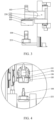
FIG. 7 is an enlarged partial view of part A ofFIG. 6 ; -
FIG. 8 is an enlarged partial view of part A ofFIG. 1 ; -
FIG. 9 is an enlarged partial view of part B ofFIG. 1 . - Illustrations of reference signs:
- first connecting
rod 101, second connectingrod 102,welding head 103,welding base 104, shapingplate 105,elastic member 106,cam 107,output shaft 108, firststationary shaft 109, drive rod 110, connection portion 111, drive part 112,tension spring 113, third connectingrod 114, fourth connectingrod 115,cylinder 116,transmission connecting rod 117, drive connectingrod 118, and thirdstationary shaft 119; -
drive unit 210,motor 211,synchronous belt 212; -
first fixing component 220, weldinghead supporting roller 221,fourth guide rail 222,cylinder fixing piece 223,fifth guide rail 224, weldinghead fixing piece 225, shapingplate fixing piece 226, and fixingupright plate 227;positioning bracket 230, outputshaft fixing piece 231, first stationaryshaft fixing piece 232,bottom plate 233,upper plate 234,first side plate 235, fixingseat 236,second side plate 237, and supportingseat 238; - first supporting
component 240,first guide rail 241, first supportingpiece 242, secondstationary shaft 243, articulated connectingrod 244; -
second fixing component 250, weldingbase support roller 251, sixth guide rail 252, and weldingbase fixing piece 253; - second supporting
component 260,second guide rail 261, second supportingpiece 262, firststaging connecting rod 263, secondstaging connecting rod 264,drive shaft 265, andthird guide rail 266. - Embodiments of the technical solution of the present application will be described in detail with reference to the accompanying drawings. The following embodiments are only intended to more clearly illustrate the technical solutions of the present application and are therefore intended as examples only and are not intended to limit the scope of protection of the present application.
- Unless otherwise defined, all technical and scientific terms used herein have the same meanings as are commonly understood by those skilled in the art of the present application. Terms used herein are for the purpose of describing specific embodiments only and are not intended to limit the application. The terms "comprising" and "having" and any variations thereof in the description and claims of the present application and the above description of the drawings are intended to cover non-exclusive inclusion.
- In the description of embodiments of the present application, the technical terms "first," "second" and the like are used only to distinguish different objects and are not understood to indicate or imply relative importance or to imply the number, specific order or primary and secondary relationship of the indicated technical features. In the description of embodiments of the present application, "plurality" means more than two, unless expressly specified otherwise.
- "Embodiments" referred to in the present application means that a particular feature, structure, or characteristic described in connection with embodiments is included in at least one embodiment of the present application. The presence of the phrase in various places in the description does not necessarily mean the same embodiment, nor is it a separate or alternative embodiment that is mutually exclusive with other embodiments. It is explicitly and implicitly understood by those skilled in the art that the embodiments described herein may be combined with other embodiments.
- In the description of embodiments of the present application, the term "and/or" herein is simply a description of the association relationship of the associated objects, indicating that three relationships can exist, for example, A and/or B may indicate that A exists alone, A and B exist at the same time, and B exists alone. In addition, the character "/" herein generally means that the associated objects are in an "or" relationship.
- In the description of the embodiments of the present application, "multiple" refers to more than two (including two). Likewise, "multiple groups" refers to more than two (including two) groups, and "multiple pieces" refers to more than two (including two) pieces.
- In the description of the embodiments of the present application, it should be understood that orientation or positional relationships indicated by terms such as "center," "longitudinal," "transverse," "length," "width," "thickness," "up," "down," "front," "back," "left," "right," "vertical," "horizontal," "top," "bottom," "inner," "outer," "clockwise," "counterclockwise," "axial," "radial," "circumferential," etc. are based on the orientation or positional relationships shown in the drawings, for ease of description of the embodiments of the present application and simplification of the description only, these terms do not indicate or imply that the apparatus or element referred to must have a specific orientation or be constructed and operated in a specific orientation, and therefore cannot be construed as limitations to the embodiments of the present application.
- In the present disclosure, unless otherwise explicitly provided and limited, the terms such as "mount," "connect," "couple," and "fix" should be understood broadly, which, for example, may refer to a fixed connection, a detachable connection, or an integral connection; which may refer to a mechanical connection or an electrical connection; which may refer to a direct connection or an indirect connection via an intermediate medium; which may also refer to a communication between the insides of two elements. To a person of normal skill in the art, specific meanings of the above terms in the present disclosure may be construed as dependent on specific situations.
- Welding, also known as fusion welding, is a manufacturing process and technology for bonding metals or other thermoplastic materials (such as plastics) by heating, high temperature or high pressure. At present, the equipment used for welding is mostly equipped with a welding base and a welding head, where the welding base is used to bear two objects to be welded together, and the welding head is used to weld the two objects to be welded together.
- The applicant notes that when the welding device is in use, it is necessary to move the welding head and welding base first to adjust the positions of the welding head and welding base, so as to facilitate the subsequent welding. However, the existing welding device cannot ensure that the welding head and the welding base can be moved simultaneously.
- In order to ensure the simultaneous movement of the welding head and the welding base, after in-depth study, a welding device is designed. With such a design, when the welding device is in use, it is necessary to move the welding head and the welding base at the same time, and the drive unit can drive the first connecting rod and the second connecting rod to move simultaneously, so that the first connecting rod drives the welding head to move in the direction close to or away from the welding base, and the second connecting rod drives the welding base to move in the direction close to or away from the welding head, thereby ensuring simultaneous movement of the welding head and the welding base.
- According to some embodiments of the present application, referring to
FIGS. 1 and 2 , the present application provides a welding device including adrive unit 210, a first connectingrod 101, a second connectingrod 102, awelding head 103, and awelding base 104. Thedrive unit 210 is connected to one end of the first connectingrod 101 and one end of the second connectingrod 102. Another end of the first connectingrod 101 is connected with thewelding head 103, and is used to drive thewelding head 103 to move in a direction close to or away from thewelding base 104 under the drive of thedrive unit 210. Another end of the second connectingrod 102 is in driving connection with thewelding base 104, and is configured for causing, being driven by thedrive unit 210, thewelding base 104 to move in a direction close to or away from thewelding head 103. - In an embodiment, when the welding device is used and before the welding device welds the object to be welded, the first connecting
rod 101 drives thewelding head 103 to move in a direction close to thewelding base 104 under the drive of thedrive unit 210, and the second connectingrod 102 drives thewelding base 104 to move in a direction close to thewelding head 103 under the drive of thedrive unit 210, so that thewelding head 103 and thewelding base 104 move in a direction close to each other, and the distance between thewelding head 103 and thewelding base 104 is reduced, so as to facilitate subsequent welding. - In another embodiment, when the welding device is used and before the welding device welds the object to be welded, the first connecting
rod 101 drives thewelding head 103 to move in a direction away from thewelding base 104 under the drive of thedrive unit 210, and the second connectingrod 102 drives thewelding base 104 to move in a direction close to thewelding head 103 under the drive of thedrive unit 210, and the displacement of thewelding base 104 moving is larger than the displacement of thewelding head 103, so as to reduce the distance between thewelding head 103 and thewelding base 104 to facilitate subsequent welding. - It should be noted that, when the welding device provided in the present application is in use and before welding the object to be welded, the direction in which the
drive unit 210 drives thewelding head 103 to move and the direction in which the drive unit drives thewelding base 104 to move are not limited, as long as thedrive unit 210 can ensure that thewelding head 103 and thewelding base 104 move simultaneously, so as to facilitate subsequent welding. - When the welding device provided by the embodiment of the present application is in use, the
welding head 103 and thewelding base 104 need to be moved simultaneously, the first connectingrod 101 and the second connectingrod 102 can be driven simultaneously by thedrive unit 210 to move thewelding head 103 in a direction close to or away from thewelding base 104 via the first connectingrod 101 and thewelding base 104 in a direction close to or away from thewelding head 103 via the second connectingrod 102, thereby ensuring that thewelding head 103 and thewelding base 104 move synchronously. - Referring to
FIGS. 3 and 4 , according to some embodiments of the present application, the welding device further includes ashaping plate 105. The shapingplate 105 is in driving connection with another end of the first connectingrod 101. The first connectingrod 101 moves thewelding head 103 and theshaping plate 105 under the drive of thedrive unit 210. - In this way, the
drive unit 210 can drive the shapingplate 105 to move while driving the first connectingrod 101 to move, so as to drive thewelding head 103 to move, so that there is no need to drive the shapingplate 105 to move by other parts, thus saving the step sequence. - Specifically, the shaping
plate 105 is used for shaping the object to be welded. In one example, the object to be welded is a conductive structure and a plurality of cells, and the welding device is used for electrically connecting the conductive structure and the plurality of cells. At this time, the shapingplate 105 is used for shaping the plurality of cells to ensure that the plurality of cells are arranged in order. The conductive structure can be a bus bar and the like. - In some embodiments, the corners of the
shaping plate 105 are chamfered, and the surface of theshaping plate 105 is coated with a smooth coating such as a Teflon coating or a ceramic coating, so as to prevent theshaping plate 105 from being scratched and damaged by an object to be shaped when the shapingplate 105 is treated with an object to be shaped. - According to some embodiments of the present application, the welding device further includes a
first fixing component 220. Thefirst fixing component 220 is connected to another end of the first connectingrod 101 and thewelding head 103. In one embodiment, thefirst fixing component 220 is connected with another end of the first connectingrod 101, thewelding head 103 and theshaping plate 105. The shapingplate 105 has a spacing between thefirst fixing component 220, and the spacing can be increased or decreased. - In the above embodiment, when the
drive unit 210 simultaneously drives thewelding head 103 and theshaping plate 105 through the first connectingrod 101, and theshaping plate 105 is used for shaping, thefirst fixing component 220 and theshaping plate 105 can squeeze theelastic member 106 by reducing the spacing, so as to prevent theshaping plate 105 from exerting excessive pressure on the shaping object during shaping, resulting in damage to the shaping object. - According to some embodiments of the present application, the welding device further includes an
elastic member 106. Theelastic member 106 is located between thefirst fixing component 220 and theshaping plate 105. When the spacing is reduced theelastic member 106 is elastically deformed by the pressing of thefirst fixing piece 220 and theshaping plate 105. - In some embodiments, the reaction force applied by the object to be shaped to the
shaping plate 105 when the spacing is reduced may also be adjusted by replacing theelastic members 106 having different modulus of elasticity. - In some embodiments, the welding device further includes a pin (not shown) by which the
first fixing component 220 is fixed to theshaping plate 105 so that the spacing between thefirst fixing component 220 and theshaping plate 105 can be increased or decreased, and anelastic member 106 is disposed adjacent to the pin and between thefirst fixing component 220 and theshaping plate 105. The number of pins may be four, and the number ofelastic members 106 may be four, each of which is disposed adjacent to one pin, and theelastic members 106 may be springs or the like. - With continued reference to
FIG. 2 and in conjunction withFIG. 5 , according to some embodiments of the present application, the welding device further includes twocams 107 and at least oneoutput shaft 108 in drive connection with thedrive unit 210 and mating with the twocams 107. One end of the first connectingrod 101 and one end of the second connectingrod 102 are both connected to onecam 107. - In this way, the
drive unit 210 can drive the twocams 107 to rotate through at least oneoutput shaft 108, so as to drive the first connectingrod 101 and the second connectingrod 102 to move, and then drive thewelding head 103 and thewelding base 104 to move. - In one embodiment, both the
cam 107 and theoutput shaft 108 are made of carbon steel, and the working surfaces of thecam 107 and theoutput shaft 108 are heat treated and polished, so that thecam 107 and theoutput shaft 108 can withstand periodic impact loads. - According to some embodiments of the present application, the number of
output shafts 108 is one and theoutput shafts 108 penetrate and are fixed to the twocams 107. Thus, it is ensured that theoutput shaft 108 can rotate the twocams 107 under the drive of thedrive unit 210. Specifically, theoutput shaft 108 can be fixed to thecam 107 by a key. - Specifically, in one example, the
drive unit 210 includes amotor 211, asynchronous belt 212, and two synchronous belt pulleys (not shown). The output end of themotor 211 is in driving connection with one synchronous pulley, and the synchronous pulley is in driving connection with another synchronous pulley via thesynchronous belt 212, and the other synchronous pulley is fixed to theoutput shaft 108, so that themotor 211 can driveoutput shaft 108 to rotate via the two synchronous pulleys and the synchronous belt. Themotor 211 may be in driving connection with the synchronous pulley via a reducer (not shown) and may be a servo motor. In one embodiment, the servo motor has a right-angle reducer to ensure that the starting torque of themotor 211 is not too large, and at the same time, the rotation angle of themotor 211 is more accurate. - According to some embodiments of the present application, the welding device further includes a first
stationary shaft 109 and two drive rods 110. The firststationary shaft 109 is axially parallel to theoutput shaft 108. The two drive rods 110 are rotatably disposed on the firststationary shaft 109 in a circumferential direction of the firststationary shaft 109. The two drive rods 110 each include a connecting part 111 and a drive part 112, and two drive parts 112 are in driving connection with one of the twocams 107. One end of the first connectingrod 101 and one end of the second connectingrod 102 are both connected to one connecting part 111. - In one embodiment, the drive rod 110 is sleeved on the first
stationary shaft 109, and the diameter of the firststationary shaft 109 is larger, so as to increase the contact area between the drive rod 110 and the firststationary shaft 109, thereby improving the stability of the drive rod 110 when rotating along the circumferential direction of the firststationary shaft 109. - In this the above embodiments, when the
drive unit 210 drives theoutput shaft 108 and brings the twocams 107 to rotate, eachcam 107 can drive one drive rod 110 to rotate circumferentially along the firststationary shaft 109 via the drive part 112, so as to drive one of the first connectingrod 101 and the second connectingrod 102 to move via two drive rods 110, and then bring thewelding head 103 and thewelding base 104 to move. Specifically, in one example, the drive part 112 is located between the connecting part 111 and the firststationary shaft 109. In another example, the connecting part 111 is located between the drive part 112 and the firststationary shaft 109. - In one embodiment, the
cam 107 in driving connection with the drive part 112 is a force-closed type cam, and the drive part 112 abuts against an outer surface of thecam 107. In this case, the welding device may further include atension spring 113. Thetension spring 113 is connected to the transmission rod 110 and used for pulling the transmission rod 110 in a direction close to thecam 107 to ensure that the drive part 112 abuts against the outer wheel surface of thecam 107. For example, the drive part 112 has bearing rollers, and the bearing rollers come into contact with the outer surface of thecam 107 to reduce friction between the drive part 112 and thecam 107. For another example, the tension springs 113 are double tension springs 113, that is, eachtension spring 113 has two tension springs, so as to increase the tension force of the tension springs 113 on the transmission rod 110 and further ensure that the drive part 112 abuts against the outer surface of thecam 107. - In yet another embodiment, the
cam 107, which is in driving connection with the drive part 112, is a closed type cam, thecam 107 is provided with an inner groove, and the drive part 112 is slidably provided in the inner groove so that thecam 107 is in driving connection with the transmission rod 110. For example, the inner groove of thecam 107 is exposed to the outside, thereby facilitating subsequent lubrication and spot check maintenance of thecam 107 in the welding device. - In some embodiments, the welding device further includes a
positioning bracket 230 fixed to thedrive unit 210. In an embodiment, theoutput shaft 108 is rotationally disposed on thepositioning bracket 230, and the firststationary shaft 109 is fixed on thepositioning bracket 230. Specifically, thepositioning bracket 230 includes two opposite outputshaft fixing pieces 231, and both ends of theoutput shaft 108 are respectively rotatable on one outputshaft fixing piece 231. In addition, thepositioning bracket 230 also includes two first stationaryshaft fixing pieces 232 disposed opposite to each other, and both ends of the firststationary shaft 109 are respectively fixed to one of the first stationaryshaft fixing pieces 232. More specifically, thepositioning bracket 230 also includes abottom plate 233. The outputshaft fixing piece 231 and the first stationaryshaft fixing piece 232 are fixed to thebottom plate 233, and themotor 211 in thedrive unit 210 is also fixed to thebottom plate 233. In one example, there is also a double row angular contact ball bearing (not shown) between the end of theoutput shaft 108 provided with a synchronous pulley and the outputshaft fixing member 231, which is used to withstand the radial load and the axial load of theoutput shaft 108. - According to some embodiments of the present application and with reference to
FIGS. 1 ,4 and8 , the welding device further includes afirst fixing component 220 and asecond fixing component 250. Thefirst fixing component 220 is connected with another end of the first connectingrod 101 and thewelding head 103. Thesecond fixing component 250 is connected to another end of the second connectingrod 102 and thewelding base 104. - In this way, when the
drive unit 210 drives the firstfixed assembly 220 to move via the first connectingrod 101, thewelding head 103 can be moved, and when thedrive unit 210 drives the secondfixed assembly 250 to move via the second connectingrod 102, thewelding base 104 can be moved. - With continued reference to
FIGS. 1 and 2 , and also toFIGS. 6 and7 , according to some embodiments of the present application, the welding device further include a first supportingcomponent 240. When thewelding head 103 is moved in a direction close to thewelding base 104, the first supportingcomponent 240 moves to a preset position and abuts against the firstfixed assembly 220 to prevent thewelding head 103 from moving in a direction away from thewelding base 104. - In this way, after the
drive unit 101 drives thefirst fixing component 220 to move via the first connectingrod 101, so as to bring thewelding head 103 to move, thewelding head 103 can be prevented from moving in the direction away from thewelding base 104 by the first supportingcomponent 240, so as to improve the stability of thewelding head 103 while welding. - According to some embodiments of the present application, the welding device further includes a third connecting
rod 114. The thirdconnecting rod 114 is in driving connection with thedrive unit 210 and the first supportingcomponent 240, and is configured for causing, being driven by thedrive unit 210, the first supportingcomponent 240 to move. - In this way, while the
drive unit 210 moves thefirst fixing component 220 via the first connectingrod 101 to move thewelding head 103, thedrive unit 210 can simultaneously move the first supportingcomponent 240 via the third connectingrod 114 so that after thewelding head 103 moves in the direction close to thewelding base 104, the first supportingcomponent 240 can abut against thefirst fixing component 220 and prevent thewelding head 103 from moving in the direction away from thewelding base 104. - According to some embodiments of the present application, the first supporting
component 240 includes afirst guide rail 241 fixed on thepositioning bracket 230, and a first supportingpiece 242 slidably arranged on thefirst guide rail 241 and in driving connection with an end portion of the third connectingrod 114; and the third connectingrod 114 is configured for driving the first supportingpiece 242 to slide on thefirst guide rail 241 and bringing the first supportingpiece 242 against thefirst fixing component 220. - In this way, the
drive unit 210 can drive the first supportingpiece 242 to slide on thefirst guide rail 241 via the third connectingrod 114, and when thedrive unit 210 moves thefirst fixing component 220 via the first connectingrod 101 to move thewelding head 103, the first supportingpiece 242 is made to abut against thefirst fixing component 220 to prevent thewelding head 103 from moving in the direction away from thewelding base 104, thereby improving the stability of thewelding head 103 and theshaping plate 105 when thewelding head 103 is being welded. - In one embodiment, a welding
head support roller 221 is provided in thefirst fixing component 220 at an abutment for abutting the first supportingpiece 242. When the first supportingpiece 242 slides on thefirst guide rail 241 and abuts against thefirst fixing component 220, the first supportingpiece 242 abuts against the weldinghead support roller 221 to reduce friction when the first supportingpiece 242 abuts against thefirst fixing component 220. - According to some embodiments of the present application, the first supporting
component 240 further includes a secondstationary shaft 243 and an articulated connectingrod 244. The secondstationary shaft 243 fixed on thepositioning bracket 230. The articulated connectingrod 244 is rotatably disposed 243 on the secondstationary shaft 243 in a circumferential direction of the secondstationary shaft 243, and opposite ends of the articulated connectingrod 244 are respectively connected with one of the third connectingrod 114 and the first supportingpiece 242. - In this way, the
drive unit 210 can drive the articulated connectingrod 244 through the third connectingrod 114 to rotate circumferentially along the secondstationary shaft 243 to slide the first supportingcomponent 240 on thefirst guide rail 241 through the articulated connectingrod 244, so that the first supportingpiece 242 can abut thefirst fixing component 220 and prevent thewelding head 103 from moving in the direction away from thewelding base 104. - Specifically, in one example, the articulated connecting
rod 244 is rotationally connected to the third connectingrod 114. In another example, the first supportingpiece 242 is provided with a slot, the end of the articulated connectingrod 244 and the first supportingpiece 242 is embedded in the slot of the first supportingpiece 242, and a roller bearing is arranged between the end of the articulated connectingrod 244 and the first supportingpiece 242 and the wall surface of the slot, so as to reduce the friction between the articulated connectingrod 244 and the first supportingpiece 242 when the articulated connectingrod 244 drives the first supportingpiece 242 to move. - In one embodiment, the
positioning bracket 230 also includes anupper plate 234 and afirst side plate 235 fixed to theupper plate 234. The plate surface of theupper plate 234 intersects the plate surface of thefirst side plate 235, and thefirst guide rail 241 and the secondstationary shaft 243 are both fixed to thefirst side plate 235. In one example, theupper plate 234 is fixed to thebottom plate 233 by a support frame (not shown), and the plate surface of theupper plate 234 is parallel to the plate surface of thebottom plate 233. - With continued reference to
FIGS. 1 and 2 , and also toFIGS. 8 , according to some embodiments of the present application In, the welding device further includes asecond fixing component 250. Thesecond fixing component 250 is connected to another end of the second connectingrod 102 and thewelding base 104. In this way, when thedrive unit 210 drives the second connectingrod 102 to move, thewelding base 104 can be moved by driving the secondfixed assembly 250 to move. - According to some embodiments of the present application, the welding device further includes a second supporting
component 260. when thewelding base 104 moves in a direction close to thewelding head 103, the second supportingcomponent 260 moves to a preset position and abuts against thesecond fixing component 250 to prevent thewelding base 104 from moving in a direction away from thewelding head 103. - In this way, after the
drive unit 210 drives thesecond fixing component 250 to move via the second connectingrod 102, so as to bring thewelding base 104 to move, and thewelding base 104 can be prevented from moving in the direction away from thewelding head 103 by the second supportingcomponent 260, so as to improve the stability of thewelding base 104 while thewelding heat 103 is being welded. - According to some embodiments of the present application, the welding device further includes a fourth connecting
rod 115. The fourth connectingrod 115 is in driving connection with thedrive unit 210 and the second supportingcomponent 260, and is configured for causing, being driven by thedrive unit 210, the second supportingcomponent 260 to move. - In this way, the
drive unit 210 can drive thesecond fixing component 260 to move via the fourth connectingrod 115 while driving thesecond fixing component 250 to move via the second connectingrod 102, so as to bring thewelding base 104 to move. - According to some embodiments of the present application, the second supporting
component 260 includes asecond guide rail 261 fixed on thepositioning bracket 230, and a second supportingpiece 262 slidably arranged on thesecond guide rail 261 and in driving connection with an end portion of the fourth connectingrod 115. The fourth connectingrod 115 is configured for driving the second supportingpiece 262 to slide on thesecond guide rail 261 and bringing the second supportingpiece 262 against thesecond fixing component 250. - In this way, the
drive unit 210 can drive the second supportingpiece 262 to slide on thesecond guide rail 261 through the fourth connectingrod 115, when thedrive unit 210 drives thesecond fixing component 250 to move through the second connectingrod 102 so as to move thewelding base 104, the second supportingmember 262 is brought into contact with thesecond fixing component 250 to prevent thewelding base 104 from moving in a direction away from thewelding head 103, thereby improving the stability of thewelding base 104 when thewelding head 103 is welded. - In one embodiment, a welding
base support roller 251 is provided at an abutment for abutting the second supportingpiece 262 in thesecond fixing component 250. When the second supportingpiece 262 slides on thesecond guide rail 261 and abuts against thesecond fixing component 250, the second supportingpiece 262 abuts against the weldingbase support roller 251 to reduce friction when the second supportingpiece 262 abuts against thesecond fixing component 250. - According to some embodiments of the present application, the second supporting
component 260 further includes a firststaging connecting rod 263, a secondstaging connecting rod 264 and adrive shaft 265. The second supportingpiece 262 is provided with athird guide rail 266, and an extension direction of thethird guide rail 266 intersects with an extension direction of thesecond guide rail 261. One end of the firststaging connecting rod 263 and one end of the secondstaging connecting rod 264 are fixed with thedrive shaft 265, another end of the firststaging connecting rod 263 is in driving connection with an end portion of the fourth connectingrod 115, and another end of the secondstaging connecting rod 264 is slidably arranged on thethird guide rail 266. Thedrive shaft 265 is rotatably arranged on thepositioning bracket 230 in a circumferential direction of the positioning bracket. - Since the extension direction of the
third guide rail 266 intersects the extension direction of thesecond guide rail 261. Therefore, when the secondstaging connecting rod 264 rotates in the circumferential direction along thedrive shaft 265 and another end of the secondstaging connecting rod 264 slides on thethird guide rail 266, the second supportingpiece 262 can be caused to slide on thesecond guide rail 261. In one example, the extension direction of thethird guide rail 266 is perpendicular to the extension direction of thesecond guide rail 261. - In this way, the
drive unit 210 can drive the firststaging connecting rod 263 to rotate circumferentially along thedrive shaft 265 via the fourth connectingrod 115, and drive the secondstaging connecting rod 264 via thedrive shaft 265 to rotate circumferentially along thedrive shaft 265, and slide on thethird guide rail 266 by means of the other end of the secondstaging connecting rod 264, causing the second supportingpiece 262 to slide on thesecond guide rail 261, thereby allowing the second supportingpiece 262 to abut thesecond fixing component 250 and preventing thewelding base 104 from moving in a direction away from thewelding head 103. - Specifically, in one example, the first
staging connecting rod 263 and the fourth connectingrod 115 are rotationally connected. In another example, thethird guide rail 266 is a groove provided on the second supportingpiece 262, and a deep groove ball bearing is provided between another end of the secondstaging connecting rod 264 and the groove wall of thethird guide rail 266 to reduce friction when another end of the secondstaging connecting rod 264 slides on thethird guide rail 266. - In one embodiment, the
positioning bracket 230 is further provided with a fixingseat 236 fixed to theupper plate 234, thesecond guide rail 261 is fixed to theupper plate 234, and thedrive shaft 265 is rotatably arranged on the fixingseat 236. - With continued reference to
FIGS. 1-4 , and also with reference toFIG. 9 , according to some embodiments of the present application, the above-described welding device further includes acylinder 116 coupled to thewelding head 103 and configured for driving thewelding head 103 to move in a direction close to or away from thewelding base 104. The another end of the first connectingrod 101 is in driving connection with thecylinder 116 and is configured for driving thecylinder 116 and thewelding head 103 to move. - In this way, when the welding device is in use, and after the
drive unit 210 drives both thewelding head 103 and thewelding base 104 to move, thewelding head 103 can be driven by thecylinder 116 to weld the object to be welded. - According to some embodiments of the present application, the
first fixing component 220 further includes afourth guide rail 222 fixed to thepositioning bracket 230. Thecylinder 116 is slidably arranged on thefourth guide rail 222 and capable of sliding, being driven by the first connectingrod 101, on thefourth guide rail 222. - In this way, when the
drive unit 210 drives thecylinder 116 to move via the first connectingrod 101, it enables thecylinder 116 to move on thefourth guide rail 222 to improve the stability of thecylinder 116 when it moves. In one embodiment, thefourth guide rail 222 includes two parallel rails, and thecylinder 116 is slidable on the two rails of thefourth guide rail 222, thereby further improving the stability of thecylinder 116 when moving. - According to some embodiments of the present application, the
first fixing component 220 further includes acylinder fixing piece 223 and afifth guide rail 224. Thecylinder fixing piece 223 is slidably arranged on thefourth guide rail 222, and thecylinder fixing piece 223 is in driving connection with the another end of the first connectingrod 101. Thefifth guide rail 224 is fixed on thecylinder fixing piece 223. Thewelding head 103 is slidably arranged on thefifth guide rail 224. Thecylinder 116 is fixed on thecylinder fixing piece 223 and is configured for driving thewelding head 103 to slide on thefifth guide rail 224. - In this way, when the
cylinder 116 drives thewelding head 103 to move in the direction close to or away from thewelding base 104, it enables thewelding head 103 to move on thefifth guide rail 224 to improve the stability of thewelding head 103 when it moves. - Specifically, in one embodiment, the
fifth guide rail 224 includes two parallel rails, and thewelding head 103 is slidable on the two rails of thefifth guide rail 224, thereby further improving the stability of thewelding head 103 when moving. In another embodiment, thecylinder fixing piece 223 is rotationally connected to another end of the first connectingrod 101. - In some embodiments, the
first fixing component 220 further includes a weldinghead fixing piece 225. The weldinghead fixing piece 225 is slidably disposed on thefifth guide rail 224, and thewelding head 103 is fixed on the weldinghead fixing piece 225. For example, thefirst fixing component 220 further includes a shapingplate fixing piece 226. The shapeplate fixing piece 226 is fixed to thecylinder fixing piece 223, and theshaping plate 105 that is fixed to theshaper fixing piece 226 with a space therebetween. In one example, thefirst fixing component 220 further includes a fixingupright plate 227. The fixingupright plate 227 is slidably disposed on thefifth guide rail 224, and the weldinghead fixing piece 225 is fixed on the fixingupright plate 227. - According to some embodiments of the present application, the
second fixing component 250 further includes a sixth guide rail 252 fixed to thepositioning bracket 230. Thewelding base 104 is slidably arranged on the sixth guide rail 252 and capable of sliding, being driven by the second connectingrod 102, on the sixth guide rail 252. - In this way, when the
drive unit 210 drives thewelding base 104 to move through the second connectingrod 102, it enables thewelding base 104 to move on the sixth guide rail 252 to improve the stability of thewelding base 104 when it moves. In one embodiment, the sixth guide rail 252 includes two parallel rails, and thewelding base 104 is slidable on the two rails of the sixth guide 252, thereby further improving the stability of thewelding base 104 when moving. In another embodiment, thesecond fixing component 250 further includes a weldingbase fixing piece 253. Thewelding base 104 is fixed to the weldingbase fixing piece 253. The weldingbase fixing piece 253 is slidably disposed on the sixth guide rail 252, and the weldingbase fixing piece 253 is rotationally connected to another end of the second connectingrod 102. - In one embodiment, the
positioning bracket 230 is further provided with asecond side plate 237, the surface of thesecond side plate 237 intersects the surface of theupper plate 234, thesecond side plate 237 is fixed to theupper plate 234, and the sixth guide rail 252 is fixed to thesecond side plate 237. - With continued reference to
FIGS. 2 and5 , according to some embodiments of the present application, the welding device further includes atransmission connecting rod 117, adrive connecting rod 118, and a thirdstationary shaft 119 fixed to thepositioning bracket 230. Thetransmission connecting rod 117 is provided on the thirdstationary shaft 119, so as to be rotatable along the circumferential direction of the thirdstationary shaft 119. Both ends of thedrive connecting rod 118 are in driving connection with one of thetransmission connecting rod 117 and thedrive unit 210. One end of the first connectingrod 101 or one end of the second connectingrod 102 is connected with thetransmission connecting rod 117. - In this way, when the
drive unit 210 drives thedrive connecting rod 118 to move, it drives thetransmission connecting rod 117 to rotate circumferentially along the thirdstationary shaft 119 and drives the first connectingrod 101 or the second connectingrod 102 to move via thetransmission connecting rod 117, thereby driving thewelding head 103 orwelding base 104 to move. In one embodiment, the thirdstationary shaft 119 is located between thedrive connecting rod 118 and the first connectingrod 101, or the thirdstationary shaft 119 is located between thedrive connecting rod 118 and the second connectingrod 102. - Specifically, in one embodiment, the number of the
transmission connecting rods 117, thedrive connecting rods 118 and the thirdstationary shafts 119 are two, and thedrive unit 210 drives the twodrive connecting rods 118 to move through theoutput shaft 108, the twocams 107 and the two drive rods 110, thereby driving one of the first connectingrod 101 and the second connectingrod 102 to move through the twodrive connecting rods 118 and the twotransmission connecting rods 117, respectively. - In some embodiments, the
drive unit 210 may drive the third connectingrod 114 and the fourth connectingrod 115 in the same manner as the first connectingrod 101 and the second connectingrod 102 in the previous embodiments. Specifically, thedrive unit 210 moves one of the third connectingrod 114 and the fourth connectingrod 115 via theoutput shaft 108, the twocams 107, the two drive rods 110, the twodrive connecting rods 118, and the twotransmission connecting rods 117, respectively. In another embodiment, the twocams 107 driving the third connectingrod 114 and the fourth connectingrod 115 are closed cams to ensure that the first supportingcomponent 240 can contact the firstfixed assembly 220 and the second supportingcomponent 260 can contact the secondfixed assembly 250 after thedrive unit 210 drives the third connectingrod 114 and the fourth connectingrod 115 to move. - In some embodiments, the
positioning bracket 230 further includes asupport seat 238 secured to the side of theupper plate 234 adjacent to thebottom plate 233, and the thirdstationary shaft 119 is secured to thesupport seat 238. In one embodiment, thesupport seat 238 is double support seats, which are respectively arranged at both ends of the thirdstationary shaft 119 and connected with the thirdstationary shaft 119, wherein thetransmission connecting rod 117 arranged on the thirdstationary shaft 119 is used for driving the third connectingrod 114 or the fourth connectingrod 115 to move. - In some embodiments, the displacement of the
head 103 and the base 104 when thedrive unit 210 is driven may be adjusted by adjusting the lengths of the first connectingrod 101, the second connectingrod 102, the third connectingrod 114, and the fourth connectingrod 115. - In one particular embodiment, the present application provides a welding device When the
welding head 103 and thewelding base 104 need to be moved synchronously, themotor 211 drives theoutput shaft 108 to rotate via thesynchronous belt 212 to rotate the fourcams 107, and each of the fourcams 107 drives the first connectingrod 101, the second connectingrod 102, the third connectingrod 114 and the fourth connectingrod 115 to move via the transmission connecting rod 110, thedrive connecting rod 118 and thetransmission connecting rod 117, thereby driving thewelding head 103 and thewelding base 104 to move and causing the first supportingpiece 242 to abut thewelding head 103 against the weldinghead support roller 221 of thefirst fixing component 220 fixing thewelding head 103 to prevent thewelding head 103 from moving in a direction away from thewelding base 104, and the second supportingpiece 262 to abut thewelding head 103 against the weldinghead support roller 251 of thesecond fixing component 250 fixing thewelding base 104 to prevent thewelding base 104 from moving in a direction away from thewelding head 103. In addition, when the welding device performs welding, thewelding head 103 and theshaping plate 105 can be simultaneously driven by thecylinder 116 to move, so that welding is performed by thewelding head 103 and shaping is performed by the shapingplate 105. - Finally, it should be noted that the above embodiments are only used to illustrate the technical solution of the present application, not to limit it. Although the present applicant has been described in detail with reference to the foregoing embodiments, it should be understood by those of ordinary skill in the art that the technical solution described in the foregoing embodiments can still be modified or some or all of the technical features thereof can be equivalently replaced. However, these modifications or substitutions do not depart the essence of the corresponding technical solution from the scope of the technical solution of each embodiment of the present application, and should be covered in the scope of the claims and descriptions of the present application. In particular, the various technical features mentioned in the various embodiments may be combined in any manner so long as there is no structural conflict. The present application is not limited to the specific embodiments disclosed herein but includes all technical solutions falling within the scope of the claims.
Claims (21)
- A welding device, comprising: a drive unit, a first connecting rod, a second connecting rod, a welding head and a welding base;wherein the drive unit is in driving connection with one end of the first connecting rod and one end of the second connecting rod;another end of the first connecting rod is in driving connection with the welding head, and is configured for causing, being driven by the drive unit, the welding head to move in a direction close to or away from the welding base;and another end of the second connecting rod is in driving connection with the welding base, and is configured for causing, being driven by the drive unit, the welding base to move in a direction close to or away from the welding head.
- The welding device according to Claim 1, further comprising a shaping plate; wherein the shaping plate is in driving connection with the another end of the first connecting rod; and the first connecting rod, being driven by the drive unit, drives the welding head and the shaping plate to move.
- The welding device according to Claim 2, further comprising a first fixing component; wherein the first fixing component is connected with the another end of the first connecting rod, the welding head and the shaping plate, and the shaping plate and the first fixing component are provided with spacing, the spacing being increased or decreased.
- The welding device according to Claim 3, further comprising an elastic member; wherein the elastic member is located between the first fixing component and the shaping plate; when the spacing is decreased, the elastic member is elastically deformed under extrusion of the first fixing component and the shaping plate.
- The welding device according to Claim 1, further comprising two cams and at least one output shaft being in driving connection with the drive unit and mated with the two cams; wherein the one end of the first connecting rod and the one end of the second connecting rod are connected with one of the two cams.
- The welding device according to Claim 5, wherein one output shaft is provided, and the output shaft penetrates through and are fixed to the two cams.
- The welding device according to Claim 5 or 6, further comprising a first stationary shaft and two drive rods; wherein the first stationary shaft is axially parallel to the output shaft; the two drive rods are rotatably disposed on the first stationary shaft in a circumferential direction of the first stationary shaft; the two drive rods each comprise a connecting part and a drive part, and two drive parts are respectively in driving connection with one of the two cams; and one end of the first connecting rod and one end of the second connecting rod are in driving connection with one connecting part.
- The welding device according to Claim 1, further comprising a first fixing component connected with the another end of the first connecting rod and the welding head; and a second fixing component connected with the another end of the second connecting rod and the welding base.
- The welding device according to Claim 8, further comprising a first supporting component; wherein when the welding head moves in a direction close to the welding base, the first supporting component moves to a preset position and abuts against the first fixing component to prevent the welding head from moving in a direction away from the welding base.
- The welding device according to Claim 9, further comprising a third connecting rod; wherein the third connecting rod is in driving connection with the drive unit and the first supporting component, and is configured for causing, being driven by the drive unit, the first supporting component to move.
- The welding device according to Claim 10, further comprising a positioning bracket fixed to the drive unit; wherein the first supporting component comprises: a first guide rail fixed on the positioning bracket, and a first supporting piece slidably arranged on the first guide rail and in driving connection with an end portion of the third connecting rod; and the third connecting rod is configured for driving the first supporting piece to slide on the first guide rail and bringing the first supporting piece against the first fixing component.
- The welding device according to Claim 11, wherein the first supporting component further comprises: a second stationary shaft fixed on the positioning bracket; and an articulated connecting rod rotatably disposed on the second stationary shaft in a circumferential direction of the second stationary shaft, and opposite ends of the articulated connecting rod being respectively connected with one of the third connecting rod and the first supporting piece.
- The welding device according to Claim 8, further comprising a second supporting component; wherein when the welding base moves in a direction close to the welding head, the second supporting component moves to a preset position and abuts against the second fixing component to prevent the welding base from moving in a direction away from the welding head.
- The welding device according to Claim 13, further comprising a fourth connecting rod; wherein the fourth connecting rod is in driving connection with the drive unit and the second supporting component, and is configured for causing, being driven by the drive unit, the second supporting component to move.
- The welding device according to Claim 14, further comprising a positioning bracket fixed to the drive unit; wherein the second supporting component comprises: a second guide rail fixed on the positioning bracket, and a second supporting piece slidably arranged on the second guide rail and in driving connection with an end portion of the fourth connecting rod; and the fourth connecting rod is configured for driving the second supporting piece to slide on the second guide rail and bringing the second supporting piece against the second fixing component.
- The welding device according to Claim 15, wherein the second supporting component further comprises: a first staging connecting rod, a second staging connecting rod, and a drive shaft; wherein the second supporting piece is provided with a third guide rail, and an extension direction of the third guide rail intersects with an extension direction of the second guide rail; one end of the first staging connecting rod and one end of the second staging connecting rod are fixed with the drive shaft, another end of the first staging connecting rod is in driving connection with an end portion of the fourth connecting rod, and another end of the second staging connecting rod is slidably arranged on the third guide rail; and the drive shaft is rotatably arranged on the positioning bracket in a circumferential direction of the positioning bracket.
- The welding device according to Claim 1, further comprising a cylinder coupled to the welding head and configured for driving the welding head to move in a direction close to or away from the welding base; and the another end of the first connecting rod is in driving connection with the cylinder and is configured for driving the cylinder and the welding head to move.
- The welding device according to Claim 17, further comprising a positioning bracket and a fourth guide rail fixed to the positioning bracket; and the cylinder is slidably arranged on the fourth guide rail and capable of sliding, being driven by the first connecting rod, on the fourth guide rail.
- The welding device according to Claim 18, further comprising a cylinder fixing piece and a fifth guide rail; wherein the cylinder fixing piece is slidably arranged on the fourth guide rail, and the cylinder fixing piece is in driving connection with the another end of the first connecting rod; the fifth guide rail is fixed on the cylinder fixing piece; the welding head is slidably arranged on the fifth guide rail; and the cylinder is fixed on the cylinder fixing piece and is configured for driving the welding head to slide on the fifth guide rail.
- The welding device according to Claim 1, further comprising a positioning bracket and a sixth guide rail fixed to the positioning bracket; wherein the welding base is slidably arranged on the sixth guide rail and capable of sliding, being driven by the second connecting rod, on the sixth guide rail.
- The welding device according to Claim 1, further comprising a transmission connecting rod, a drive connecting rod, a positioning bracket, and a third stationary shaft fixed to the positioning bracket; wherein the transmission connecting rod is rotatably arranged on the third stationary shaft in a circumferential direction of the third stationary shaft; two ends of the drive connecting rod are respectively in driving connection with one of the transmission connecting rod and the drive unit; and one end of the first connecting rod or one end of the second connecting rod is connected with the transmission connecting rod.
Applications Claiming Priority (2)
| Application Number | Priority Date | Filing Date | Title |
|---|---|---|---|
| CN202111192761.8A CN115958332B (en) | 2021-10-13 | 2021-10-13 | Welding equipment |
| PCT/CN2022/124365 WO2023061328A1 (en) | 2021-10-13 | 2022-10-10 | Welding device |
Publications (4)
| Publication Number | Publication Date |
|---|---|
| EP4205898A1 true EP4205898A1 (en) | 2023-07-05 |
| EP4205898A4 EP4205898A4 (en) | 2024-07-10 |
| EP4205898B1 EP4205898B1 (en) | 2025-08-20 |
| EP4205898C0 EP4205898C0 (en) | 2025-08-20 |
Family
ID=85903618
Family Applications (1)
| Application Number | Title | Priority Date | Filing Date |
|---|---|---|---|
| EP22871137.0A Active EP4205898B1 (en) | 2021-10-13 | 2022-10-10 | Welding device |
Country Status (6)
| Country | Link |
|---|---|
| US (1) | US12023763B2 (en) |
| EP (1) | EP4205898B1 (en) |
| CN (1) | CN115958332B (en) |
| ES (1) | ES3052696T3 (en) |
| HU (1) | HUE073499T2 (en) |
| WO (1) | WO2023061328A1 (en) |
Cited By (1)
| Publication number | Priority date | Publication date | Assignee | Title |
|---|---|---|---|---|
| CN117733344A (en) * | 2024-02-21 | 2024-03-22 | 山西建投装备制造有限公司 | Automatic welding equipment and method for standard joint of construction lifter |
Families Citing this family (2)
| Publication number | Priority date | Publication date | Assignee | Title |
|---|---|---|---|---|
| CN117283180B (en) * | 2023-11-03 | 2024-02-23 | 山东兴都电器有限公司 | Automatic welding device for electric oven production |
| CN118321814B (en) * | 2024-06-07 | 2024-08-23 | 中国建筑第五工程局有限公司 | Welding device for steel structure factory building construction |
Family Cites Families (23)
| Publication number | Priority date | Publication date | Assignee | Title |
|---|---|---|---|---|
| US2236823A (en) * | 1939-05-16 | 1941-04-01 | Truscon Steel Co | Multiple welder |
| US2441043A (en) * | 1945-05-18 | 1948-05-04 | Ames Spot Welder Co Inc | Spot-welding machine |
| US2727122A (en) * | 1952-03-29 | 1955-12-13 | Sylvania Electric Prod | Resistance welder |
| US3303316A (en) * | 1964-02-19 | 1967-02-07 | Bogosian Arda | Method and means for electric welding |
| DE3745065C1 (en) * | 1987-06-06 | 1994-05-19 | Stapla Ultraschalltechnik Gmbh | Method for connecting electrical conductors and device for carrying out the method |
| GB2221416B (en) * | 1988-06-22 | 1992-05-06 | Honda Motor Co Ltd | Method and apparatus for supplying electric power to resistance welding gun |
| JPH08267252A (en) * | 1995-03-30 | 1996-10-15 | Nissan Motor Co Ltd | X type spot welding gun |
| SE9501251D0 (en) * | 1995-04-03 | 1995-04-03 | Attexor Equip | Merhod and apparatus for carrying out an operatopn on a mechanical workpiece |
| US7690548B2 (en) * | 2005-01-03 | 2010-04-06 | 3M Innovative Properties Company | Apparatus of adjusting the position of an ultrasonic welding horn |
| KR101341394B1 (en) * | 2013-05-06 | 2013-12-13 | 한복우 | A soldering device |
| JP6069174B2 (en) * | 2013-05-31 | 2017-02-01 | 東洋自動機株式会社 | Ultrasonic sealing device for bagging and packaging machine |
| CN104044268B (en) * | 2014-06-19 | 2016-02-17 | 国家林业局哈尔滨林业机械研究所 | Non-woven fabrics woods seedling-raising cup ultrasonic brazing unit |
| KR101883126B1 (en) * | 2014-10-15 | 2018-07-27 | 닛산 지도우샤 가부시키가이샤 | Ultrasonic bonding device and ultrasonic bonding method |
| CN206010131U (en) * | 2016-08-09 | 2017-03-15 | 无锡先驱自动化科技有限公司 | A kind of up and down dynamic formula Welding head mechanism |
| CN206869301U (en) * | 2017-03-29 | 2018-01-12 | 昆明理工大学 | A kind of resistance spot welding prepressing device |
| CN207668797U (en) * | 2017-12-25 | 2018-07-31 | 无锡奥特维科技股份有限公司 | A kind of interconnection welder |
| CN207952921U (en) * | 2018-02-02 | 2018-10-12 | 宁波市鄞州腾进机械有限公司 | Reciprocating folding welding mechanism for bag-spring machine |
| CN108708950A (en) * | 2018-07-28 | 2018-10-26 | 惠州市成泰自动化科技有限公司 | Point back welding cam gear |
| CN110340506A (en) * | 2019-07-04 | 2019-10-18 | 佛山市昱纶机械有限公司 | A pocket spring welding device |
| CN210648979U (en) * | 2019-07-04 | 2020-06-02 | 佛山市昱纶机械有限公司 | Bagged spring welding device |
| CN211683543U (en) * | 2019-12-12 | 2020-10-16 | 常青智能科技(天津)有限公司 | Ultrasonic welding station lifting device |
| KR102277363B1 (en) * | 2020-04-06 | 2021-07-15 | 한국조선해양 주식회사 | Automatic welding carriage and welding method |
| CN213560504U (en) * | 2020-08-27 | 2021-06-29 | 广东普电自动化科技股份有限公司 | AC bump welder |
-
2021
- 2021-10-13 CN CN202111192761.8A patent/CN115958332B/en active Active
-
2022
- 2022-10-10 EP EP22871137.0A patent/EP4205898B1/en active Active
- 2022-10-10 ES ES22871137T patent/ES3052696T3/en active Active
- 2022-10-10 WO PCT/CN2022/124365 patent/WO2023061328A1/en not_active Ceased
- 2022-10-10 HU HUE22871137A patent/HUE073499T2/en unknown
-
2023
- 2023-04-07 US US18/132,119 patent/US12023763B2/en active Active
Cited By (2)
| Publication number | Priority date | Publication date | Assignee | Title |
|---|---|---|---|---|
| CN117733344A (en) * | 2024-02-21 | 2024-03-22 | 山西建投装备制造有限公司 | Automatic welding equipment and method for standard joint of construction lifter |
| CN117733344B (en) * | 2024-02-21 | 2024-05-10 | 山西建投装备制造有限公司 | Automatic welding equipment and method for standard joint of construction lifter |
Also Published As
| Publication number | Publication date |
|---|---|
| CN115958332A (en) | 2023-04-14 |
| EP4205898A4 (en) | 2024-07-10 |
| US12023763B2 (en) | 2024-07-02 |
| HUE073499T2 (en) | 2026-01-28 |
| CN115958332B (en) | 2024-06-04 |
| WO2023061328A1 (en) | 2023-04-20 |
| EP4205898B1 (en) | 2025-08-20 |
| ES3052696T3 (en) | 2026-01-13 |
| US20230241727A1 (en) | 2023-08-03 |
| EP4205898C0 (en) | 2025-08-20 |
Similar Documents
| Publication | Publication Date | Title |
|---|---|---|
| EP4205898A1 (en) | Welding device | |
| CN218903362U (en) | Heating element and multi-point nondestructive straightening device | |
| CN113385563B (en) | Torsional bending method and bending mechanism of wiper connecting rod | |
| CN114739828B (en) | A mechanical properties testing device for welded metal parts of suspended magnetic levitation vehicles | |
| CN118175743A (en) | Pressfitting circuit board transfer device | |
| CN117140145B (en) | A high accuracy hydraulic clamp for cylinder cap processing | |
| CN210907534U (en) | Automatic bending device for chassis pipe of handcart | |
| CN220683650U (en) | Roller way device and roller way conveying line | |
| CN218560159U (en) | Jacking transfer machine | |
| CN215785930U (en) | Horizontal pipe bending device | |
| CN218641734U (en) | Centering device and stepping conveying equipment | |
| CN224157566U (en) | Steel structure processing and bending device with positioning and clamping components | |
| CN222180341U (en) | A universal logistics turnover device for automobile muffler core | |
| CN223960807U (en) | Welding clamping device | |
| CN220426402U (en) | Bending tool for long-strip TC4 titanium alloy forging stock | |
| CN222291780U (en) | A support and limit bracket for the turnover of logistics equipment | |
| CN223685385U (en) | Pipe fitting placing device for water supply and drainage engineering construction | |
| CN117020094B (en) | Roller forging table | |
| CN216858738U (en) | Web centering assembly of heavy H-shaped steel assembling machine | |
| CN223699202U (en) | A ring rolling mill mounting structure for gearbox flange forgings | |
| CN223916492U (en) | An inclined steel bar bending machine | |
| CN222680196U (en) | Tool for processing guard ring | |
| CN223766577U (en) | Moving device for hair flattening machine | |
| CN217599545U (en) | Adjustable conveying device | |
| CN221966449U (en) | Limiting mechanism of aluminum coil uncoiling flat-bed machine |
Legal Events
| Date | Code | Title | Description |
|---|---|---|---|
| STAA | Information on the status of an ep patent application or granted ep patent |
Free format text: STATUS: UNKNOWN |
|
| STAA | Information on the status of an ep patent application or granted ep patent |
Free format text: STATUS: THE INTERNATIONAL PUBLICATION HAS BEEN MADE |
|
| PUAI | Public reference made under article 153(3) epc to a published international application that has entered the european phase |
Free format text: ORIGINAL CODE: 0009012 |
|
| STAA | Information on the status of an ep patent application or granted ep patent |
Free format text: STATUS: REQUEST FOR EXAMINATION WAS MADE |
|
| 17P | Request for examination filed |
Effective date: 20230331 |
|
| AK | Designated contracting states |
Kind code of ref document: A1 Designated state(s): AL AT BE BG CH CY CZ DE DK EE ES FI FR GB GR HR HU IE IS IT LI LT LU LV MC ME MK MT NL NO PL PT RO RS SE SI SK SM TR |
|
| A4 | Supplementary search report drawn up and despatched |
Effective date: 20240607 |
|
| RIC1 | Information provided on ipc code assigned before grant |
Ipc: B23K 20/02 20060101ALI20240603BHEP Ipc: F16H 25/00 20060101ALI20240603BHEP Ipc: B23K 37/02 20060101ALI20240603BHEP Ipc: B23K 37/00 20060101AFI20240603BHEP |
|
| RAP1 | Party data changed (applicant data changed or rights of an application transferred) |
Owner name: CONTEMPORARY AMPEREX TECHNOLOGY(HONG KONG) LIMITED |
|
| DAV | Request for validation of the european patent (deleted) | ||
| DAX | Request for extension of the european patent (deleted) | ||
| GRAP | Despatch of communication of intention to grant a patent |
Free format text: ORIGINAL CODE: EPIDOSNIGR1 |
|
| STAA | Information on the status of an ep patent application or granted ep patent |
Free format text: STATUS: GRANT OF PATENT IS INTENDED |
|
| INTG | Intention to grant announced |
Effective date: 20250424 |
|
| GRAS | Grant fee paid |
Free format text: ORIGINAL CODE: EPIDOSNIGR3 |
|
| GRAA | (expected) grant |
Free format text: ORIGINAL CODE: 0009210 |
|
| STAA | Information on the status of an ep patent application or granted ep patent |
Free format text: STATUS: THE PATENT HAS BEEN GRANTED |
|
| AK | Designated contracting states |
Kind code of ref document: B1 Designated state(s): AL AT BE BG CH CY CZ DE DK EE ES FI FR GB GR HR HU IE IS IT LI LT LU LV MC ME MK MT NL NO PL PT RO RS SE SI SK SM TR |
|
| REG | Reference to a national code |
Ref country code: GB Ref legal event code: FG4D |
|
| REG | Reference to a national code |
Ref country code: CH Ref legal event code: EP |
|
| REG | Reference to a national code |
Ref country code: DE Ref legal event code: R096 Ref document number: 602022020005 Country of ref document: DE |
|
| REG | Reference to a national code |
Ref country code: IE Ref legal event code: FG4D |
|
| U01 | Request for unitary effect filed |
Effective date: 20250912 |
|
| U07 | Unitary effect registered |
Designated state(s): AT BE BG DE DK EE FI FR IT LT LU LV MT NL PT RO SE SI Effective date: 20250919 |
|
| U20 | Renewal fee for the european patent with unitary effect paid |
Year of fee payment: 4 Effective date: 20251021 |
|
| PGFP | Annual fee paid to national office [announced via postgrant information from national office to epo] |
Ref country code: HU Payment date: 20251007 Year of fee payment: 4 |
|
| PG25 | Lapsed in a contracting state [announced via postgrant information from national office to epo] |
Ref country code: IS Free format text: LAPSE BECAUSE OF FAILURE TO SUBMIT A TRANSLATION OF THE DESCRIPTION OR TO PAY THE FEE WITHIN THE PRESCRIBED TIME-LIMIT Effective date: 20251220 |
|
| PG25 | Lapsed in a contracting state [announced via postgrant information from national office to epo] |
Ref country code: NO Free format text: LAPSE BECAUSE OF FAILURE TO SUBMIT A TRANSLATION OF THE DESCRIPTION OR TO PAY THE FEE WITHIN THE PRESCRIBED TIME-LIMIT Effective date: 20251120 |
|
| REG | Reference to a national code |
Ref country code: ES Ref legal event code: FG2A Ref document number: 3052696 Country of ref document: ES Kind code of ref document: T3 Effective date: 20260113 |
|
| PG25 | Lapsed in a contracting state [announced via postgrant information from national office to epo] |
Ref country code: HR Free format text: LAPSE BECAUSE OF FAILURE TO SUBMIT A TRANSLATION OF THE DESCRIPTION OR TO PAY THE FEE WITHIN THE PRESCRIBED TIME-LIMIT Effective date: 20250820 |
|
| PG25 | Lapsed in a contracting state [announced via postgrant information from national office to epo] |
Ref country code: GR Free format text: LAPSE BECAUSE OF FAILURE TO SUBMIT A TRANSLATION OF THE DESCRIPTION OR TO PAY THE FEE WITHIN THE PRESCRIBED TIME-LIMIT Effective date: 20251121 |
|
| PG25 | Lapsed in a contracting state [announced via postgrant information from national office to epo] |
Ref country code: PL Free format text: LAPSE BECAUSE OF FAILURE TO SUBMIT A TRANSLATION OF THE DESCRIPTION OR TO PAY THE FEE WITHIN THE PRESCRIBED TIME-LIMIT Effective date: 20250820 |
|
| PG25 | Lapsed in a contracting state [announced via postgrant information from national office to epo] |
Ref country code: RS Free format text: LAPSE BECAUSE OF FAILURE TO SUBMIT A TRANSLATION OF THE DESCRIPTION OR TO PAY THE FEE WITHIN THE PRESCRIBED TIME-LIMIT Effective date: 20251120 |
|
| REG | Reference to a national code |
Ref country code: HU Ref legal event code: AG4A Ref document number: E073499 Country of ref document: HU |
|
| PGFP | Annual fee paid to national office [announced via postgrant information from national office to epo] |
Ref country code: ES Payment date: 20251104 Year of fee payment: 4 |
|
| PG25 | Lapsed in a contracting state [announced via postgrant information from national office to epo] |
Ref country code: SM Free format text: LAPSE BECAUSE OF FAILURE TO SUBMIT A TRANSLATION OF THE DESCRIPTION OR TO PAY THE FEE WITHIN THE PRESCRIBED TIME-LIMIT Effective date: 20250820 |
|
| PG25 | Lapsed in a contracting state [announced via postgrant information from national office to epo] |
Ref country code: CZ Free format text: LAPSE BECAUSE OF FAILURE TO SUBMIT A TRANSLATION OF THE DESCRIPTION OR TO PAY THE FEE WITHIN THE PRESCRIBED TIME-LIMIT Effective date: 20250820 |
|
| PG25 | Lapsed in a contracting state [announced via postgrant information from national office to epo] |
Ref country code: SK Free format text: LAPSE BECAUSE OF FAILURE TO SUBMIT A TRANSLATION OF THE DESCRIPTION OR TO PAY THE FEE WITHIN THE PRESCRIBED TIME-LIMIT Effective date: 20250820 |