EP4205814A1 - Mask ear loop, mask, method for producing mask ear loop, and method for producing mask - Google Patents
Mask ear loop, mask, method for producing mask ear loop, and method for producing mask Download PDFInfo
- Publication number
- EP4205814A1 EP4205814A1 EP21861275.2A EP21861275A EP4205814A1 EP 4205814 A1 EP4205814 A1 EP 4205814A1 EP 21861275 A EP21861275 A EP 21861275A EP 4205814 A1 EP4205814 A1 EP 4205814A1
- Authority
- EP
- European Patent Office
- Prior art keywords
- ear
- ear hook
- mask
- portions
- coupling
- Prior art date
- Legal status (The legal status is an assumption and is not a legal conclusion. Google has not performed a legal analysis and makes no representation as to the accuracy of the status listed.)
- Granted
Links
Images




Classifications
-
- A—HUMAN NECESSITIES
- A62—LIFE-SAVING; FIRE-FIGHTING
- A62B—DEVICES, APPARATUS OR METHODS FOR LIFE-SAVING
- A62B23/00—Filters for breathing-protection purposes
- A62B23/02—Filters for breathing-protection purposes for respirators
- A62B23/025—Filters for breathing-protection purposes for respirators the filter having substantially the shape of a mask
-
- A—HUMAN NECESSITIES
- A41—WEARING APPAREL
- A41D—OUTERWEAR; PROTECTIVE GARMENTS; ACCESSORIES
- A41D13/00—Professional, industrial or sporting protective garments, e.g. surgeons' gowns or garments protecting against blows or punches
- A41D13/05—Professional, industrial or sporting protective garments, e.g. surgeons' gowns or garments protecting against blows or punches protecting only a particular body part
- A41D13/11—Protective face masks, e.g. for surgical use, or for use in foul atmospheres
- A41D13/1161—Means for fastening to the user's head
-
- A—HUMAN NECESSITIES
- A62—LIFE-SAVING; FIRE-FIGHTING
- A62B—DEVICES, APPARATUS OR METHODS FOR LIFE-SAVING
- A62B18/00—Breathing masks or helmets, e.g. affording protection against chemical agents or for use at high altitudes or incorporating a pump or compressor for reducing the inhalation effort
- A62B18/08—Component parts for gas-masks or gas-helmets, e.g. windows, straps, speech transmitters, signal-devices
- A62B18/084—Means for fastening gas-masks to heads or helmets
Definitions
- the present invention relates to an ear hook portion for a mask, a mask, a method for manufacturing an ear hook portion for a mask, and a method for manufacturing a mask.
- a known configuration of a mask to be worn on the face includes: a mask body that at least partially covers the face of a wearer; and ear hook portions, constituting a pair, each being coupled to the mask body, i.e., a pair of members that can be hung on the ears of the wearer in order to hold the mask body at a wearing position.
- a sheet-shaped ear hook used for a mask is known.
- a mask disclosed in PTL 1 includes a single sheet-shaped ear hook sheet extending on the same plane with both ear hook portions connected to each other at the connection portion.
- PTL 1 indicates that the ear hook portion is made of a stretchable spunbond nonwoven fabric or the like.
- a portion of the sheet-shaped ear hook portion which extends in the left-and-right direction of the face as disclosed in PTL 1 is easily stretched when being put on. It is preferable that the portion of the ear hook portion situated behind the ear when the mask is put on (while the mask is worn) is not stretched and deformed so much, because the state of contact with the skin behind the ear can be stably maintained. Therefore, it is desirable that the stretching characteristic or the deformation characteristic of the sheet-shaped ear hook portion is different depending on the position in order to improve the ease of wearing and fit. However, such a study has not been made in the past.
- an object of one aspect of the present invention to provide an ear hook portion for a mask that is improved in ease of wearing and fit.
- One aspect of the present invention is an ear hook portion for mask, the ear hook portion being made of a material including: a stretchable portion material; and a first surface sheet material and a second surface sheet material coupled, via a plurality of coupling portions, to both surfaces of the stretchable portion material in such a state that the stretchable portion material is stretched, the ear hook portion including: a proximal portion fixed to a mask body; an ear back placement portion to be situated at a back of an ear of a wearer; an upper transition portion extending, on an upper side, from the proximal portion to the ear back placement portion; and lower transition portion transitioning, on a lower side, from the proximal portion to the ear back placement portion, wherein a number of the plurality of coupling portions per unit area in the ear back placement portion is greater than a number of the plurality of coupling portions per unit area in at least one of the upper transition portion and the lower transition portion.
- an ear hook portion for a mask that is improved in ease of wearing and fit can be provided.
- the mask according to the present embodiment may be a mask capable of covering the face of a wearer, more specifically, covering at least the nose and the mouth of a wearer.
- the mask according to this embodiment can have a function of preventing foreign matter from reaching the face and preventing droplets generated by the wearer from being scattered, and is also referred to as a sanitary mask or surgical mask.
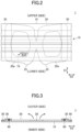
- FIG. 1 is a plan view of a mask 1.
- FIG. 1 is a view of the mask 1 as seen from the outside, i.e., from the side exposed to the outside and facing away from the face when the mask 1 is worn.
- FIG. 2 is a plan view of the mask 1 as seen from the inside (face side).
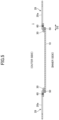
- FIG. 3 is a cross-sectional view taken along line I-I of FIG. 1 .
- the mask 1 includes: a mask body 10 which is disposed in front of the face of the wearer when the mask is worn and can mainly cover the nose and mouth of the wearer; and ear hook portions 20a, 20a, constituting the pair, coupled to the mask body 10.
- the mask body 10 has a height direction (height direction) D1 corresponding to the height direction of the wearer's face when wearing the mask and a left-and-right direction (left-and-right direction) D2 orthogonal to the height direction D1.
- the mask body 10 has a rectangular shape in a plan view having long sides in the left-and-right direction D2, but the shape of the mask body 10 in a plan view is not limited to the shape as illustrated in the drawings.
- the mask body 10 has a pleated structure 15 formed by multiple pleats arranged side by side in the height direction D1.
- the pleats of the pleated structure 15 are formed by folding a sheet constituting the body 10 at fold lines along the left-and-right direction D2.
- the side portions (the ends in the left-and-right direction D2) of the mask body 10 are joined and fixed by pressure bonding or the like.
- the pleats of the pleated structure 15 are extended in the height direction D1, so that the center in the left-and-right direction D2 is curved so as to protrude toward the outer surface side of the mask 1, and can be deformed into a shape adapted to the three-dimensional shape of the face.
- the specific configuration of the pleated structure 15 is not particularly limited and may be a conventional configuration formed in a mask body.
- the mask body 10 may have a multilayer structure formed by laminating multiple layers.
- the structure may include at least three layers sandwiched between an outer layer and an inner layer of an intermediate layer having an enhanced function of collecting a foreign matter (dust, pollen, bacteria, viruses, and the like).
- Each layer constituting the mask body 10 preferably includes a fiber-containing layer such as a nonwoven fabric, a woven fabric, a knitted fabric, and the like, and more preferably includes a nonwoven fabric.
- the nonwoven fabric include a spunbond nonwoven fabric, a spunlace nonwoven fabric, a meltblown nonwoven fabric, an air through nonwoven fabric, a point bond nonwoven fabric, and the like.
- a meltblown nonwoven fabric which can contain fine fibers is preferably used for the intermediate layer.
- the fibers constituting the fiber-containing layer are preferably resin fibers, and the resin types of the resin fibers include polyethylene, polypropylene, polyethylene terephthalate, nylon, and the like.
- the basis weight of the outer and inner layers may be 10 to 50 g/m 2 , preferably 15 to 50 g/m 2 .
- the basis weight of the intermediate layer having a high foreign matter collecting property is preferably 10 to 100 g/m 2 and more preferably 15 to 50 g/m 2 .
- the ear hook portions 20a, 20a, constituting the pair may be in an annular shape (or in a closed belt shape), or may have a shape that includes an annulus in a plan view.
- the ear hook portions 20a can be hung on the ears by allowing the ears of the wearer to enter the inside of the ring of each ear hook portion 20a, i.e., an opening 29 at the center of each ear hook portion 20a.
- the ear hook portions 20a, 20a, constituting the pair is formed as a single sheet-shaped or a continuous ear hook portion sheet 20 in which the ear hook portions 20a, 20a are separably coupled to each other at the center in the left-and-right direction D2.
- the term "single sheet” herein refers to a form composed of one continuous sheet, and the "single sheet” is a concept that can include a stacked body in which multiple layers are stacked.
- the ear hook portions 20a, 20a, constituting the pair are in a sheet form, and therefore, when the ear hook portion 20a is hung on the ear, the ear hook portion 20a can be brought into surface contact with the back surface behind the ear (or the back of the ear), i.e., the skin on the rear side with respect to the ear and/or the back of the earlobe, so that the load on the ear can be reduced. Accordingly, even when worn for a long period of time, pain and discomfort can be reduced.
- the ear hook portions 20a, 20a, constituting the pair are in a sheet form (i.e., constituted by the ear hook portion sheet 20), the ear hook portions 20a, 20a, constituting the pair, can be positioned at the same time during manufacturing, and therefore, manufacturing of the mask is also easy.
- the ear hook portion sheet 20 is configured so as to be able to form the ear hook portions 20a, 20a, constituting the pair, separated from each other by breaking the ear hook portion sheet 20 at a predetermined position at the start of use.
- the ear hook portions 20a, 20a, constituting the pair are coupled by a coupling portion 28.
- the type of coupling at a separable coupling portion 28 between the ear hook portions 20a, 20a constituting the pair is not particularly limited, but is preferably separable by pulling with a usual force of the user. For example, it may be formed as perforations as illustrated in FIG. 1 .
- the coupling portion 28 may also be formed by reducing the thickness of the sheet or by other means to weaken the border between the ear hook portions 20a, 20a constituting the pair or to increase stress.
- the ear hook portions 20a, 20a, constituting the pair, or the ear hook portion sheet 20 in a single sheet shape are superposed on the mask body 10.
- the ear hook portion sheet 20 may have a shape and a size that does not protrude from the mask body 10 at least in the left-and-right direction D2 in a plan view.
- a length of the ear hook portion sheet 20 in the left-and-right direction D2 may be 70 to 95% of the length of the mask 1 in the left-and-right direction D2.
- masks can be continuously manufactured by superposing and coupling the mask body 10 and the ear hook portion sheet 20 without requiring complicated processes such as folding and bending of the ear hook portion sheet 20.
- the length of one ear hook portion 20a in the left-and-right direction D2 is 60 to 90 mm, preferably 65 to 85 mm.
- the ear hook portions 20a, 20a, constituting the pair may be directly or indirectly coupled to side portions (end portions in the left-and-right direction D2) of the body 10. Specifically, the portions on the outer sides of the ear hook portions 20a, 20a, constituting the pair, in the left-and-right direction D2 are connected to the body 10, and the other portions are not connected to the body 10.
- the user releases the coupling, at the coupling portion 28, between the ear hook portions 20a, 20a, constituting the pair, separates the ear hook portions 20a, 20a from each other (also referred to as a separation operation), and opens, sideways in the left-and-right direction D2, the portions of the ear hook portions 20a, 20a that are not coupled to the body 10 (also referred to as an expansion operation).
- the ear hook portions 20a, 20a may be coupled to both side portions of the mask body 10 via sheet-shaped auxiliary materials 30, 30, respectively.
- the auxiliary material 30 By interposing the auxiliary material 30 in the coupling between the ear hook portion 20a and the mask body 10, the mask 1 can be formed without directly coupling the ear hook portion 20a and the mask body 10. Therefore, the coupling between the ear hook portion 20a and the auxiliary material 30 and the coupling between the mask body 10 and the auxiliary material 30 can be formed separately in appropriate forms. In addition, it is possible to avoid using a portion of the ear hook portion 20a for fixation with the mask body 10.
- the ear hook portion 20a can be moved more freely relative to the mask body 10 than in the case where the ear hook portion 20a is directly coupled to the mask body 10, and the position of the ear hook portion 20a relative to the ear can be set more freely when the ear hook portion 20a is attached to the ear.
- the mask body 10 and the sheet-shaped auxiliary material 30 are superposed and coupled at a first side coupling portion 50.
- the sheet-shaped ear hook portion 20a and the sheet-shaped auxiliary material 30 are superposed and coupled at a second side coupling portion 60.
- the auxiliary material 30 may be a sheet-shaped member extending in the entire height direction D1 of the mask 1.
- the length (width) W of the auxiliary material 30 in the left-and-right direction D2 is preferably 15 to 35 mm, depending on the size and configuration of the entire mask 1 and the sizes, shapes, and materials of the body 10 and the ear hook portions 20a.
- the basis weight of the auxiliary material 30 may be 5 to 100 g/m2.
- the thickness of the auxiliary material 30 may be 100 to 1,000 ⁇ m.
- the auxiliary material 30 may be formed of a non-stretchable material or a material with small stretchability, or may be formed of a material having a certain degree of stretchability.
- the auxiliary material 30 may include, for example, a stretchable nonwoven fabric.
- the auxiliary material 30 is preferably stretchable at least in the left-and-right direction D2, but the stretchability of the auxiliary material 30 is preferably smaller than that of the ear hook portion 20a.
- the auxiliary material 30 may be formed of a material whose shape can be irreversibly deformed when a force is applied.
- first side coupling portion 50 and the second side coupling portion 60 can be formed by means of coupling the opposing surfaces of the members by applying pressure and/or heat, such as heat sealing, ultrasonic sealing, non-heating embossing, and the like. Among them, it is preferable to use heat sealing because reliable bonding is possible.
- the length in the left-right direction D2 of the ear hook portion sheets 20 constituting the pair of ear hook portions 20a, 20a is shorter than the length in the left-right direction D2 of the mask 1.
- an outer end 21 of the ear hook portion 20a in the left-right direction D2 and an outer end 11 of the body 10 in the left-right direction D2 can be shifted, so that the auxiliary material 30 can be pasted to a position in proximity to the end portion of the mask body 10 in the left-right direction D2 that is not covered with the ear hook portion 20a.
- the user can pull the ear hook portions 20a, 20a constituting the pair in the opposite directions by pinching or holding them with their respective hands.
- the separable coupling portion 28 can be first uncoupled. If the coupling portion 28 includes perforations formed along the border line between the ear hook portions 20a, 20a constituting the pair, the perforations can be broken to separate the ear hook portions 20a, 20a along the border line. Thereafter, the user can open the ear hook portions 20a, 20a constituting the pair outward (as indicated by arrows) in the left-and-right direction D2 toward the sides indicated by the arrows in FIG. 3 while holding the ear hook portions 20a, 20a, constituting the pair.
- FIG. 4 illustrates a state in which the ear hook portions 20a, 20a, constituting the pair, are opened outward in the left-and-right direction D2 from the state illustrated in FIG. 1 .
- FIG. 5 is a cross-sectional view taken along line II-II of FIG. 4 . As illustrated in FIGs. 4 and 5 , when the ear hook portions 20a, 20a constituting the pair are opened, the ear hook portions 20a, 20a are turned over, i.e., the surface of the ear hook portions 20a, 20a constituting the pair facing the body 10 in the state before start of use is exposed.
- the mask body 10 is placed on the face of the wearer so that the surface on the face side of the mask body 10 faces the face of the wearer, and the ear hook portions 20a, 20a are hung on the respective ears of the wearer.
- the ear hook portions 20a, 20a, constituting the pair (the ear hook portion sheet 20) in the form of a single sheet are superposed on the mask body 10.
- the ear hook portions 20a, 20a, constituting the pair may be superposed on any of the surfaces of the mask body 10, but it is preferable that they are superposed on the outer surface of the mask body 10 as illustrated in the drawing.
- the contact with the inner surface (surface on the face side) of the mask body 10 can be reduced or substantially eliminated.
- the mask 1 when the user puts the mask 1 on himself/herself, the mask 1 is placed on his/her face so that the inner surface of the mask body 10 faces his/her face, and while pressing the outer surface of the mask body 10 with one hand, the coupling of the ear hook portions 20a, 20a at the coupling portion 28 is released by the other hand, and one ear hook portion 20a is hung on the ear. After switching the hand holding the mask body 10 to the other hand, the other ear hook portion 20a can be hung on the ear with the hand that was originally holding the mask body 10.
- the user opens the ear hook portions 20a, 20a, constituting the pair, outwardly in the left-and-right direction D2 by holding them with hands. Thereafter, the mask 1 is moved to the face of another wearer while the ear hook portions 20a, 20a constituting the pair are held, and the mask body 10 is arranged at a desired position of the wearer's face, and at this occasion, the ear hook portions 20a, 20a constituting the pair can be hung on the ears of the wearer while the way of holding the mask 1 is not changed. Therefore, the mask 1 according to the present embodiment can be suitably used when the mask is worn by a person who has difficulty wearing the mask by himself or herself, such as a child or a sick person.
- the user may also hold the tab portions 25, 25 protruding outward from the respective rings of the ear hook portions 20a, 20a in a plan view.
- the tab portions 25, 25 protrude beyond the outer edge of the mask body 10, particularly beyond the lower end of the mask body 10.
- a mark 18 that allows front and back (the outer and inner surfaces) of the body 10 to be distinguished from each other may be formed on the outer surface and/or the inner surface of the body 10 by embossing, printing, sewing, or the like.
- the form of the mark 18 is not limited as long as it can be visually recognized by the user. As illustrated in FIGs. 1 and 2 , the mark 18 may be letters, numbers, a symbol, a figure, a logo, or the like. If the mark 18 includes characters, the side on which the user can read the characters correctly can be recognized as the outer surface.
- FIG. 6 (a) is a partially enlarged cross-sectional view of a material constituting the ear hook portion 20a or the ear hook portion sheet 20 taken along the left-and-right direction D2.
- the material constituting the ear hook portion 20a or the ear hook portion sheet 20 may be a sheet obtained by laminating multiple layers.
- the material is provided with a stretchable material (a stretchable film) 5, and a first surface sheet material 2 is provided on a first surface that is one of the surfaces of the stretchable material (a stretchable film) 5, and a second surface sheet material 3 is provided on a second surface that is a surface on the side opposite from the first surface.
- the stretchable portion material is a portion material that can be stretched in at least one direction by applying a tensile force, and that has a property of returning to an original length (natural length) when the applied tensile force is released (an external force is not applied).
- a stretchable film 5 is used as a stretchable portion material.
- materials of the stretchable film 5 include polyolefin such as polyethylene and polypropylene, polyurethane, and the like.
- the maximum stretch rate is 3.5 to 4.0 times the natural length, as measured by a tensile testing machine.
- the stretchable film 5 may have a function of allowing moisture to pass through.
- a thread-like stretchable body aggregate formed by arranging side by side multiple thread-like stretchable bodies (or thread-like elastic bodies) such as yarn rubber may be provided.
- a stretchable portion member in the form of a film i.e., a film in the form of a flat molded body having a substantially uniform thickness, is preferable in that high stretchability or extensibility is obtained and handling during manufacture is easy.
- the first surface sheet material and the second surface sheet material are coupled to both surfaces (the first surface and the second surface) of the stretchable film 5 by multiple coupling portions 40, 40, ..., in a state where the stretchable film 5 is stretched.
- a tensile external force T is applied to the stretchable film 5 to stretch the stretchable film 5 from its natural length, and the first surface sheet material 2 and the second surface sheet material 3 are intermittently coupled at multiple coupling portions 40, 40, ... (to be described later) in the natural state in which the first surface sheet material 2 and the second surface sheet material 3 are not shrunk. Thereafter, the tensile external force T is released to relax the stretchable film 5, so that the material in the natural state illustrated in FIG. 6 (a) is obtained.
- the state of the material illustrated in FIG. 6 (a) is the natural state, i.e., a state in which no external force is applied (a state having a natural length).
- the first surface sheet material 2 and the second surface sheet material 3, which are flat when the tensile external force T illustrated in FIG. 6 (b) is applied, are formed with wrinkles (pleats), and are wavy in a cross section ( FIG. 6 (a) ). This is because, when the length of the stretchable film 5 returns to the natural length, portions other than the portions coupled by the multiple coupling portions 40, 40, ... rise so as to be separated from the stretchable film 5.
- the ear hook portion 20a (the ear hook portion sheet 20) . Therefore, when the surface of the ear hook portion 20a comes into contact with the skin, the material of the ear hook portion 20a does not come into contact with the entire surface of the skin, and a space is formed between the ear hook portion 20a and the skin, so that the feeling of sticking to the skin can be reduced and the fit can be improved.
- the stretch direction (extension direction) of the stretchable film 5 is configured to follow the left-and-right direction D2 of the mask. As a result, multiple wrinkles extending approximately along the height direction D1 of the mask 1 are formed on the surface of the ear hook portion 20a (the ear hook portion sheet 20).
- the first surface sheet material 2 and the second surface sheet material 3 may be the same or different.
- the first surface sheet material 2 and the second surface sheet material 3 preferably have a fiber structure.
- the fiber structures include a nonwoven fabric, a woven fabric, a knitted fabric, and the like.
- a nonwoven fabric is preferably used because of its good touch and breathability, and it contributes to the fit.
- nonwoven fabric include an air-through nonwoven fabric, a spunbond nonwoven fabric, a spunlace nonwoven fabric, a needle punch nonwoven fabric, a chemical bond nonwoven fabric, and the like.
- a spunbond nonwoven fabric having no pilling and high strength, an air-through nonwoven fabric having softness, and the like can be suitably selected.
- the fibers contained in the nonwoven fabric are preferably resin fibers, and the resin types of the resin fibers include polyethylene, polypropylene, polyethylene terephthalate, nylon, and the like.
- the basis weight of the nonwoven fabric may be 5 to 50 g/m 2 , and more particularly, preferably 8 to 25 g/m 2 .
- the ear hook portion 20a is made of a material in which both surfaces of the stretchable film 5 are covered by the first surface sheet material 2 and the second surface sheet material 3, direct contact between the stretchable film 5 and the skin can be avoided when the mask is worn, and the fit can be improved.
- the coupling portions 40, 40, ... can be formed by using fusing means such as ultrasonic sealing or heat sealing, or by using an adhesive or the like, but it is preferable to form the coupling portions by fusing means, especially by ultrasonic sealing, because it enables more reliable bonding.
- the first surface sheet material 2, the stretchable film 5, and the second surface sheet material 3 all contain a thermoplastic resin or are made of a thermoplastic resin, and therefore, at the coupling portions (fused portions) 40, 40, ..., the three layers are fused and integrated by welding the layers together. Depending on the formation conditions of the fused portion, a through hole may be formed in the bonded portion. In this case, the breathability y of the ear hook portion 20a (the ear hook portion sheet 20) can be improved.
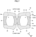
- FIG. 7 is a plan view of the ear hook portions 20a, 20a (the ear hook portion sheet 20) according to the present embodiment.
- the ear hook portion 20a may be in an annular shape (or in a closed belt shape) in a plan view, or may have a shape that includes an annulus.
- the ear hook portion 20a may include a proximal portion 22 fixed to the mask body 10 (coupled to the mask body 10 via the auxiliary material in the form of FIG.
- an ear back placement portion 24 situated behind the ear of the wearer, an upper transition portion 23 transitioning, above the ear hook portion 20a, from the proximal portion 22 to the ear back placement portion 24, and a lower transition portion 26 transitioning, below the ear hook portion 20a, from the proximal portion 22 to the ear back placement portion 24.
- the proximal portion 22 and the ear back placement portion 24 extend substantially along the height direction D1 and are opposed to each other.
- the upper transition portion 23 and the lower transition portion 26 extend approximately along the left-and-right direction D2 and face each other.
- the shape of the ring included in the ear hook portion 20a is generally a rectangular belt shape, but may be generally a circular or elliptical shape.
- the ear hook portion 20a may have a shape having three places where the direction is greatly changed along the circumferential direction of the ring (i.e., a triangular belt shape) or a shape having five or more such places (i.e., a polygonal belt shape other than the rectangular belt shape).
- the ear hook portions 20a, 20a are made of the material described above, i.e., a material including: the stretchable portion member 5; and the first surface sheet material 2 and the second surface sheet material 3 coupled to each other by multiple coupling portions 40, 40, ... in a state where the stretchable portion member 5 is stretched.
- the distribution of the multiple coupling portions 40, 40, ... is not uniform.
- the ear hook portions 20a, 20a include: sparse distribution areas R1 A , R1 B (which may be collectively referred to as R1) in which the coupling portions 41, 41, ... are sparsely distributed; and a dense distribution area R2 in which the coupling portions 42, 42, ... are more densely distributed. It is preferable that the sparse distribution areas R1 A , R1 B have the same configuration.
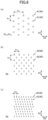
- FIG. 8 (a) is a partially enlarged plan view of the sparse distribution areas R1 A , R1 B .
- FIG. 8 (b) is a partially enlarged plan view of the dense distribution area R2.
- the density of the formed coupling portions 42, 42, ..., i.e., a number N 2 per unit area is greater than the density of the coupling portions 41, 41, ... formed in the sparse distribution areas R1 A , R1 B , i.e., a number N 1 per unit area.
- the number per unit area is the number measured in the maximum stretched state of the ear hook portion 20a or the ear hook portion sheet 20.
- the maximum stretched state refers to a state in which the surface sheet material becomes a natural length by stretching the ear hook portion 20a or the ear hook portion sheet 20, i.e., a state in which the wrinkles of the surface sheet material are not substantially seen.
- the ear back placement portion 24 may have the dense distribution area R2, the upper transition portion 23 may have the upper sparse distribution area R1 A , and the lower transition portion 26 may have the lower sparse distribution area R1 B . Furthermore, the ear back placement portion 24 may include the dense distribution area R2, the upper transition portion 23 may include the upper sparse distribution area R1 A , and the lower transition portion 26 may include the lower sparse distribution area R1 B . Therefore, the number of coupling portions per unit area in the ear back placement portion 24 is greater than the number of coupling portions per unit area in the upper transition portion 23 and greater than the number of coupling portions per unit area in the lower transition portion 26.
- the proximal portion 22 also includes the dense distribution area R2, and the proximal portion 22 does not necessarily have the dense distribution area R2.
- the belt-shaped dense distribution area R2 can be continuously formed along the conveying direction (corresponding to the left-and-right direction D2) of the ear hook portion sheet band 20A serving as the ear hook portion sheet 20 (explained later with reference to FIGs. 9 and 10 ).
- the sparse distribution areas R1 A , R1 B can also be formed in a continuous belt shape along the conveying direction on both sides of the dense distribution area R2 in the belt shape.
- the coupling portion is formed more densely in the ear back placement portion 24 means that the first surface sheet material 2, the stretchable portion member 5, and the second surface sheet material 3 are fixed together at more positions per unit area in the ear back placement portion 24. Therefore, the ear back placement portion 24 has a relatively large resistance to stretching and is not easily stretched. Since the ear back placement portion 24 is usually worn such that it is in surface contact with the back of the ear, i.e., the skin on the rear side with respect to the ear and/or the back of the earlobe, and therefore, when the ear back placement portion 24 is greatly stretched and deformed, discomfort may occur due to friction with the skin. However, according to the above configuration of the present embodiment, such discomfort can be reduced.
- the coupling portion is formed more densely, the first surface sheet material 2, the stretchable portion member 5, and the second surface sheet material 3 are less likely to be detached, and the strength of the ear back placement portion 24 is increased. Therefore, even if a relatively large force is applied to the vicinity of the coupling portion 28 in the separation operation of the ear hook portions 20a, 20a, constituting the pair, the structure of the material is less likely to be broken.
- the coupling points are formed more sparsely, and this means that the number of positions where the first surface sheet material 2, the stretchable portion member 5, and the second surface sheet material 3 are fixed together is relatively small per unit area. Therefore, the upper transition portion 23 and the lower transition portion 26 have a relatively small resistance to tension and are easily stretched. Therefore, while putting on the mask, it is possible to smoothly carry out the operation of hanging the ear hook portions 20a, 20a on the ear, in which the upper transition portion 23 and the lower transition portion 26 can be stretched in the left-and-right direction D2 with a relatively small force.
- the densities of the coupling portions 40, 40, ... are changed to change the stretching characteristic depending on the position of the ear hook portion 20a, so that the fit can be improved by reducing discomfort while being worn, and the operating for putting on the mask is facilitated.
- the edge portion of the stretchable film 5 is easily pulled inward from the edge portion of the first surface sheet material 2 and the edge portion of the second surface sheet material 3 due to compressive stress acting in the surface direction at the cutting position.
- the first surface sheet material 2 and the second surface sheet material 3 project from the edge, they can be easily detached off from the edge.
- the edge is likely to come into contact with the skin, so that the possibility of detachment can be higher than other portions of the ear hook portion 20a. Therefore, since the ear back placement portion 24 has the dense distribution area R2 having a large number of coupling portions 40, 40, ... per unit area, the above described drawing-in of the stretchable film 5 hardly occurs, and the ear back placement portion 24 hardly breaks.
- the appearance may be reduced, but if the stretchable film 5 can be prevented from being pulled in the ear back placement portion 24, which is conspicuous, the appearance of not only the ear hook portions 20a, 20a but also the entire mask 1 can be improved.
- the number N 2 per unit area of the coupling portions 42, 42, ... in the dense distribution area R2 is preferably 2 to 50 pieces/cm 2 , and more preferably 8 to 34 pieces/cm 2 .
- the number N 1 per unit area of the coupling portions 41, 41, ... in the sparse distribution area R1 may be 1 to 20 pieces/cm 2 , and more preferably 5 to 15 pieces/cm 2 .
- the ratio (N 2 /N 1 ) of the number N 2 per unit area of the coupling portions 42, 42, ... in the dense distribution area R2 to the number N 1 per unit area of the coupling portions 41, 41, ... in the sparse distribution area R1 preferably 1.5 to 2.5, and more preferably 1.75 to 2.25.
- the area S 2 of each one of the coupling portions 42 in the dense distribution area R2 may be smaller than the area S 1 of each one of the coupling portions 41 in the sparse distribution area R1.
- the ear back placement portion 24 includes the dense distribution area R2, and therefore, the upper transition portion 23 includes the upper sparse distribution area R1 A , and the lower transition portion 26 includes the lower sparse distribution area R1 B , and therefore, the area of each one of the coupling portions in the ear back placement portion 24 may be smaller than the area of each one of the coupling portions in the upper transition portion 23 and smaller than the area of each one of the coupling portions in the lower transition portion 26.
- the area S2 of each one of the coupling portions 42 in the dense distribution area R2 is small, and therefore, deformation such as curving or bending of the entire dense distribution area R2 can be performed more freely. Since the ear back placement portion 24 includes the dense distribution area R2, the ear back placement portion 24 can be deformed to conform to the shape of the portion behind the ear of the user and/or the shape of the ear. Furthermore, if the area of each one of the coupling portions is excessively large, the user may feel the hardness when it comes into contact with the skin, which may lead to discomfort. Therefore, the unpleasantness or discomfort can be reduced by reducing the area S 2 of each one of the coupling portions 42 in the ear back placement portion 24 pressed against the portion behind the ear and/or the back side of the ear.
- the area of the coupling portion being small means that the peripheral length per area of the coupling portion is long.
- the detaching starts at the peripheral edge of the coupling portion where the coupling portion is particularly strongly coupled, and therefore, since the peripheral length per area of the coupling portion is long, resistance to detachment of the first surface sheet material 2, the stretchable portion member 5, and the second surface sheet material 3 from each other at the initial stage also increases. Therefore, the ear back placement portion 24 including the dense distribution area R2 can be configured to be less likely to be detached and to be stronger.
- the area S2 of each one of the coupling portions 42 in the dense distribution area R2 is preferably 0.02 to 0.72 mm 2 , more preferably 0.08 to 0.45 mm 2 .
- the area S1 of each one of the coupling portions 41 in the sparse distribution area R1 is preferably 0.2 to 0.8 mm 2 , more preferably 0.3 to 0.6 mm 2 .
- the ratio (S2/S1) of the area S2 of each one of the coupling portions 42 in the dense distribution area R2 to the area S1 of each one of the coupling portions 41 in the sparse distribution area R1 is preferably 0.1 to 0.9, and more preferably 0.25 to 0.75.
- a pitch p x2 in the left-and-right direction D2 between the coupling portions 42, 42, ... in the dense distribution area R2 may be smaller than a pitch p x1 in the left-and-right direction D2 of the coupling portions 41, 41, ... in the sparse distribution area R1.
- the ear back placement portion 24 includes the dense distribution area R2, the upper transition portion 23 includes upper sparse distribution area R1A, and the lower transition portion 26 includes the lower sparse distribution area R1B, so that the pitch of the coupling portion in the left-and-right direction D2 in the ear back placement portion 24 may be smaller than the pitch of the coupling portion in the left-and-right direction D2 in the upper transition portion 23 and smaller than the pitch of the coupling portion in the left-and-right direction D2 in the lower transition portion 26.
- the pitch of the coupling portions in the left-and-right direction D2 is small, the intervals at which the first surface sheet material 2, the stretchable portion member 5, and the second surface sheet material 3 are fixed is small in the left-and-right direction D2. Since the ear hook portions 20a, 20a (the ear hook portion sheet 20) are stretched mainly in the left-and-right direction D2, the ease of stretch of the ear back placement portion 24 and the ease of stretch of the upper transition portion 23 and the lower transition portion 26 can be further changed depending on the difference in the pitch in the left-and-right direction D2, so that the fit can be improved and the effect of facilitating the operation for putting on the mask can be further enhanced.
- the pitch p x2 of the coupling portions 42, 42, ... in the left-right direction D2 in the dense distribution area R2 may also be smaller than the pitch p x1 of the coupling portions 41, 41, ... in the left-right direction D2 in the sparse distribution area R1.
- the pitch of the coupling portion in the left-and-right direction D2 in the ear back placement portion 24 may be smaller than the pitch of the coupling portion in the left-and-right direction D2 in the upper transition portion 23, and may be smaller than the pitch of the coupling portion in the left-and-right direction D2 in the lower transition portion 26.
- the pitch p x2 of the coupling portion 42 in the left-and-right direction D2 in the dense distribution area R2 is preferably 0.3 to 13.5 mm, more preferably 1.25 to 7.5 mm.
- the pitch p x1 of the coupling portion 41 in the left-and-right direction in the sparse distribution area R1 is preferably 3 to 15 mm, more preferably 5 to 10 mm.
- the ratio (p x2 /p x1 ) of the pitch p x2 of the coupling portion 42 in the left-and-right direction in the dense distribution area R2 to the pitch p x1 of the coupling portion 41 in the left-and-right direction in the sparse distribution area R1 is preferably 0.1 to 0.9, and more preferably 0.25 to 0.75.
- the pitch is a pitch measured in the maximum stretch state of the ear hook portion 20a or the ear hook portion sheet 20.
- a pitch p y2 of the coupling portions 42, 42, ... in the height direction D1 in the dense distribution area R2 may be either smaller or larger than or about the same as the pitch p y1 of the coupling portions 41, 41, ... in the height direction D1 in the sparse distribution area R1.
- the pitch p y2 of the coupling portions 42, 42, ... in the height direction D1 in the dense distribution area R2 is preferably smaller than the pitch p y1 of the coupling portions 41, 41, ... in the height direction D1 in the sparse distribution area R1, because the coupling portions 42, 42, ... in the dense distribution area R2 can be formed more densely.
- the coupling portions 40, 40, ... in the plan view are preferably arranged in a zigzag pattern, but may be arranged in a lattice pattern. Alternatively, the arrangement may be neither zigzag nor lattice.
- a row of coupling portions arranged along the left-and-right direction D2 may be arranged side by side in the height direction D1, and adjacent rows may be slightly shifted in the left-and-right direction D2 by a distance smaller than 1/2 of the pitch p x2 in the left-and-right direction D2.
- the shape of the coupling portion 40 may be circular ( FIG. 8 (a) ), elliptical ( FIGs. 8 (b) and (c) ), or other shapes, for example, a polygonal shape, regardless of whether it is in the sparse distribution area R1 or the dense distribution area R2.
- the shape of the coupling portion 41 in the sparse distribution area R1 may be different from the shape of the coupling portion 42 in the dense distribution area R2.
- the shape of the coupling portion 42 in the dense distribution area R2 is an elliptical shape having a long diameter in the height direction D1
- the length of the coupling portion 42 in the left-and-right direction D2 can be shortened, so that the interval of the wrinkles formed in the material can be reduced and the height of the wrinkles can be made smaller, and accordingly, the appearance can be improved.
- the sum of the areas of the multiple coupling portions 40, 40, ... may be 1 to 20% of the areas of the ear hook portions 20a, 20a (the ear hook portion sheet 20).
- the ratio of the area of the multiple coupling portions 40, 40, ... is a value measured in the maximum stretch state of the ear hook portion 20a or the ear hook portion sheet 20.
- FIG. 9 is a schematic view of a manufacturing apparatus 300 of masks.
- the manufacturing apparatus 300 of the masks is provided with a manufacturing apparatus 100 of ear hook portions on the upstream thereof. Subsequently, a mask member combining apparatus 200 for combining the manufactured ear hook portion for the mask with other members of the mask is provided.
- the manufacturing apparatus 100 of the ear hook portions is provided with a stretchable film band supply means 123 for supplying a stretchable film band (stretchable member band) 5A for forming a stretchable film 5, a first surface sheet material band supply means 121 for supplying a first surface sheet material band 2A for forming a first surface sheet material 2, and a second surface sheet material band supply means 122 for supplying a second surface sheet material band 3A for forming a second surface sheet material 3.
- a stretchable film band supply means 123 for supplying a stretchable film band (stretchable member band) 5A for forming a stretchable film 5
- a first surface sheet material band supply means 121 for supplying a first surface sheet material band 2A for forming a first surface sheet material
- a second surface sheet material band supply means 122 for supplying a second surface sheet material band 3A for forming a second surface sheet material 3.
- a long material i.e., a stretchable film band 5A, a first surface sheet material band 2A, and a second surface sheet material band 3A are supplied from each supply means, and then the first surface sheet material band 2A and the second surface sheet material band 3A are placed on one surface (first surface) and the other surface (second surface) of the stretchable film band 5A, respectively, to form a multilayer structure 6A.
- the multilayer structure 6A is conveyed in a conveying direction Dt.
- the stretchable film band 5A is conveyed in a state of being stretched in the conveying direction Dt, i.e., in a state of applying a tensile force (tension) in the conveying direction Dt.
- the degree of stretching of the stretchable film band 5A is controlled by the feeding speed of the stretchable film band supply means 123 and conveying means (not illustrated).
- the stretchable film band 5A is preferably stretched, for example, about 1.5 to 4 times, preferably about 2 to 3 times, of the natural length.
- the first surface sheet material band 2A and the second surface sheet material band 3A are conveyed in a state having a natural length (a state in which they are not pulled). Therefore, the surfaces of the first surface sheet material band 2A and the second surface sheet material band 3A laid on the respective surfaces of the stretchable film band 5A have a state without wrinkles.
- the multilayer structure 6A is fed to the coupling means 140, so that discontinuous coupling portions, i.e., welded portions, are formed over the entire multilayer structure 6A between the stretchable film band 5A and the first surface sheet material band 2A and between the stretchable film band 5A and the second surface sheet material band 3A.
- the coupling means 140 is preferably ultrasonic sheet means, but other means such as welding may be used.
- the stacked body 8A can be obtained by coupling the layers of the multilayer structure 6A at the multiple discontinuous coupling portions with the coupling means 140.
- FIG. 9 also illustrates an enlarged cross-sectional view of portion III.
- Multiple coupling portions 40, 40, ... are intermittently formed between the stretchable film band 5A and the first surface sheet material band 2A and between the stretchable film band 5A and the second surface sheet material band 3A.
- areas having different densities of the coupling portions 40, 40, ... are formed in the obtained ear hook portions 20a, 20a (the ear hook portion sheet 20) (described later with reference to FIG. 10 ) .
- the stacked body 8A is fed to relaxing means 160.
- the tension applied to the stretchable film band 5A in the conveying direction Dt is loosened.
- the degree to which the tension is loosened by the relaxing means 160 is not limited, it is preferable that the tension is loosened until the stretchable film band 5A returns to its natural length.
- the stretchable film band 5A is contracted by relaxing the stretchable film band 5A.
- the first surface sheet material band 2A, the stretchable film band 5A, and the second surface sheet material band 3A are coupled by the coupling portions 40, 40, ..., and are fixed at these positions.
- the stretchable film band 5A when the stretchable film band 5A is contracted and the length is shortened, the portions of the first surface sheet material 2 and the second surface sheet material 3 which are not coupled by the coupling portions 40, 40, ... loosen without following the stretchable film band 5A, and rise from the surface (see also FIG. 6 ). Therefore, the first surface sheet material band 2A and the second surface sheet material band 3A are formed with a large number of small pleats extending along a direction orthogonal to the conveying direction Dt. In the first surface sheet material band 2A and the second surface sheet material band 3A, no force occurs or substantially no force occurs to return to the original length when the pleats are formed.
- FIG. 9 also illustrates an enlarged cross-sectional view of the portion IV.
- the stretchable film band 5A is flat, but the first surface sheet material band 2A and the second surface sheet material band 3A are shrunk to form wrinkles.
- the ear hook portion sheet band 20A continuous irregularities are formed along the conveying direction Dt as seen in a cross section obtained by cutting the first surface sheet material band 2A and the second surface sheet material band 3A along the conveying direction Dt.
- the ear hook portion sheet band 20A is fed to punching means 180.
- the punching means 180 the ear hook portion sheet band 20A is punched by a punching die so as to obtain the shape of each ear hook portion sheet 20.
- multiple ear hook portion sheets 20, 20, ... can be obtained by the punching means 180.
- a method for manufacturing the ear hook portion sheet 20 includes: while the stretchable film band 5A including a first surface and a second surface on a side opposite to the first surface is stretched in the predetermined direction (the conveying direction Dt), placing the first surface sheet material band 2A and the second surface sheet material band 3A on the respective surfaces of the stretchable film band 5A; coupling the stretchable film band 5A with the first surface sheet material band 2A and the second surface sheet material band 3A to obtain the stacked body 8A in which the first surface sheet material band 2A, the stretchable film band 5A, and the second surface sheet material band 3A are coupled at multiple coupling portions; causing the stacked body 8A to contract in the predetermined direction (the conveying direction Dt); and cutting the stacked body 8A to form multiple ear hook portion sheets 20 constituting a pair of ear hook portions separably coupled to each other.
- the ear hook portion sheets 20, 20, ... are fed to the mask member combining apparatus 200.
- an auxiliary material band 30A is provided on one surface of the ear hook portion sheet 20.
- the mask member combining apparatus 200 includes a mask body band supply means 221 for supplying a mask body band 10A for forming a mask body.
- the mask body band supply means 221 supplies the mask body band 10A to a surface of the ear hook portion sheet 20 that is opposite to the surface where the auxiliary material band 30A is provided.
- the auxiliary material band 30A is disposed on the outermost side, but may be disposed between the ear hook portion sheet 20 and the mask body band 10A.
- the first side coupling portion 50 and the second side coupling portion 60 ( FIGs. 1 and 3 and the like) described above are formed, and are coupled at predetermined positions by heat sealing or the like by a coupling and cutting unit 240. Subsequently to the coupling or at the same time as the coupling, cutting is performed. Thus, each of the masks 1 can be obtained.
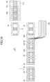
- FIG. 10 schematically illustrates, in a plan view, processes of the mask ear hook portion manufacturing apparatus 100 and the mask member combining apparatus 200.
- areas in which the degrees of densities of the coupling portions 40, 40, ... are different i.e., the sparse distribution area R1 A , R1 B , and the dense distribution area R2, are formed along the conveying direction Dt.
- the sparse distribution area R1 A , R1 B , and the dense distribution area R2 are formed in a belt-like shape adjacent to a direction orthogonal to the conveying direction Dt (the width direction of the ear hook portion sheet band 20A).
- the ear hook portion sheet band 20A having the sparse distribution area R1 A , R1 B and the dense distribution area R2 is punched by punching means 180 to obtain the ear hook portion sheet 20.
- the sparse distribution area R1 A , R1 B and the dense distribution area R2 which are continuous along the conveying direction Dt, are formed adjacent to each other in the direction orthogonal to the conveying direction Dt in the ear hook portion sheet band 20A, so that the degree of density of the coupling portion 40 can be changed by the ear back placement portion 24 of the ear hook portion 20a to be obtained, the upper transition portion 23, and the lower transition portion 26 without greatly changing the setting of the coupling means 140.
- the obtained ear hook portion sheet 20 is separated and further conveyed, and one auxiliary material band 30A is coupled to the side portion of the ear hook portion. After being coupled to the mask body band 10A, the auxiliary material band 30A and the mask body band 10A are cut to form individual masks 1.
- an ear hook portion for mask being made of a material including: a stretchable portion material; and a first surface sheet material and a second surface sheet material coupled, via a plurality of coupling portions, to both surfaces of the stretchable portion material in such a state that the stretchable portion material is stretched, the ear hook portion including: a proximal portion fixed to a mask body; an ear back placement portion to be situated at a back of an ear of a wearer; an upper transition portion extending, on an upper side, from the proximal portion to the ear back placement portion; and lower transition portion transitioning, on a lower side, from the proximal portion to the ear back placement portion, wherein a number of the plurality of coupling portions per unit area in the ear back placement portion is greater than a number of the plurality of coupling portions per unit area in at least one of the upper transition portion and the lower transition portion.
- the material is formed to include a stretchable portion material; and a first surface sheet material and a second surface sheet material coupled, via a plurality of coupling portions, to both surfaces of the stretchable portion material in such a state that the stretchable portion material is stretched.
- a desired stretch can be achieved by adjusting the degree of stretch of the stretchable portion material when the material is manufactured, and therefore, the ear hook portion having a high stretchable can be obtained.
- the material has many small wrinkles on the first surface sheet material and the second surface sheet material, so that the material is microscopically in discontinuous contact with the skin, and therefore has a good touch.
- the coupling points are formed densely in the ear back placement portion.
- the first surface sheet material, the stretchable portion member, and the second surface sheet material are both fixed at a relatively large number of positions per unit area, the resistance to tension is relatively large and the sheet material is not easily stretched.
- the ear back placement portion is usually attached to the back of the ear, i.e., the skin on the rear side with respect to the ear and/or the back of the earlobe in a state of being in contact with the surface, when the ear back placement portion is greatly stretched and deformed, discomfort may occur due to friction with the skin.
- coupling points are sparsely formed.
- the portion where the first surface sheet material, the stretchable portion member, and the second surface sheet material are fixed together is relatively small per unit area, the resistance to tension is relatively small and the sheet material is easily stretched. Therefore, the mask can be put on relatively smoothly.
- the fit can be improved by reducing discomfort when being put on, and the operation for putting on the mask can be performed easily.
- an area of each of the plurality of coupling portions in the ear back placement portion is smaller than an area of each of the plurality of coupling portions in at least one of the upper transition portion and the lower transition portion.
- the area of each one of the plurality of coupling portions is smaller in the ear back placement portion, so that the perimeter per area of the coupling portion is longer.
- the detachment starts at the peripheral edge of the coupling portion, so that when the perimeter per area of the coupling portion increases, resistance to detachment of the first surface sheet material, the stretchable portion member, and the second surface sheet material from each other increases. Therefore, according to the present embodiment, the ear back placement portion can be made more resistant to detachment and made stronger.
- each one of the coupling portions in the ear back placement portion is reduced, deformation such as curving or bending of the entire ear back placement portion becomes easier, so that the ear back placement portion can be deformed to conform to the shape of the portion behind the ear of the user and/or the shape of the ear.
- a pitch of the plurality of coupling portions in a left-and-right direction in the ear back placement portion is smaller than a pitch of the plurality of coupling portions in the left-and-right direction in at least one of the upper transition portion and the lower transition portion.
- the pitch of the plurality of coupling portions in the left-and-right direction in the ear back placement portion is smaller, and the pitch of the plurality of coupling portions in the left-and-right direction in the upper transition portion and/or the lower transition portion is larger.
- the upper transition portion and/or the lower transition portion are easier to stretch than the ear back placement portion, especially in the left-and-right direction, and the operation of stretching the ear hook portion in the left-and-right direction when being put on becomes smoother.
- the coupling portion is a fused portion in which the stretchable portion material, the first surface sheet material, and the second surface sheet material are fused together.
- the coupling portion is a fused portion, and therefore, the first surface sheet material, the stretchable portion member, and the second surface sheet material can be more integrally coupled in a more reliable manner.
- the stretchable portion material is a stretchable film.
- the stretchable portion member is made in the form of a film, high stretchability can be obtained. Furthermore, the ear hook portion can be easily manufactured.
- the first surface sheet material and the second surface sheet material includes a nonwoven fabric.
- the first surface sheet material and the second surface sheet material which can directly come into contact with the skin uses a nonwoven fabric, so that it is possible to impart softness to the surface of the ear hook portion and to improve the fit of the ear hook portion.
- the aspect according to Supplementary Note 7 is a mask that includes a mask body; and an ear hook portion sheet configured such that ear hook portions for the mask according to any one of Supplementary Notes 1 to 6 constitute a pair, and ear back placement portions of the ear hook portions for the mask are separably coupled with each other.
- auxiliary materials are provided on both side portions of the mask body, wherein the proximal portions of the ear hook portions are coupled to the mask body via the auxiliary materials.
- the mask can be formed without directly coupling the ear hook portion and the mask body, and therefore, the coupling portion between the ear hook portion and the auxiliary material and the coupling portion between the mask body and the auxiliary material can be formed separately in appropriate coupling forms. Furthermore, it is possible to avoid using a portion of the ear hook portion for adhesion to the mask body, and therefore, the ear hook portions can be moved more freely with respect to the mask body than in the case where the ear hook portions are directly coupled to the mask body, so that, the degree of freedom in the wearing positions of the ear hook portions is increased.
- the aspect according to Supplementary Note 9 is a method for manufacturing an ear hook portion for a mask, the method including: (a1) while a stretchable portion material band is stretched in a predetermined direction, placing a first surface sheet material band and a second surface sheet material on respective surfaces of the stretchable portion material band; (a2) coupling, at a plurality of coupling portions, the first surface sheet material band, the stretchable portion material band, and the second surface sheet material band to obtain a stacked body; (a3) causing the stacked body to contract in the predetermined direction; (a4) cutting the stacked body to form ear hook portion sheets each including a pair of ear hook portions separably coupled to each other, wherein each of the ear hook portions for the mask includes: a proximal portion fixed to a mask body; an ear back placement portion to be situated at a back of an ear of a wearer; an upper transition portion extending, on an upper side, from the proximal portion to the ear back placement portion; and a lower transition portion transition
- the method for manufacturing the ear hook portion for the mask that exhibits substantially the same effects as those described with regard to the above-described aspect of the Supplementary Note 1 can be provided.
- the aspect according to Supplementary Note 10 is a method for manufacturing a mask, the method including: (a) manufacturing ear hook portion sheets for the mask by the method for manufacturing the ear hook portion according to claim 9; (b) coupling an auxiliary material band to side portions of two ear hook portion sheets, spaced apart from each other, of the ear hook portion sheets; (c) coupling the auxiliary material band to a mask body band; and (d) cutting the auxiliary material band and the mask body band to form the mask.
Landscapes
- Health & Medical Sciences (AREA)
- General Health & Medical Sciences (AREA)
- Business, Economics & Management (AREA)
- Emergency Management (AREA)
- Physical Education & Sports Medicine (AREA)
- Engineering & Computer Science (AREA)
- Textile Engineering (AREA)
- Pulmonology (AREA)
- Respiratory Apparatuses And Protective Means (AREA)
Abstract
Description
- The present invention relates to an ear hook portion for a mask, a mask, a method for manufacturing an ear hook portion for a mask, and a method for manufacturing a mask.
- A known configuration of a mask to be worn on the face includes: a mask body that at least partially covers the face of a wearer; and ear hook portions, constituting a pair, each being coupled to the mask body, i.e., a pair of members that can be hung on the ears of the wearer in order to hold the mask body at a wearing position.
- A sheet-shaped ear hook used for a mask is known. For example, a mask disclosed in
PTL 1 includes a single sheet-shaped ear hook sheet extending on the same plane with both ear hook portions connected to each other at the connection portion.PTL 1 indicates that the ear hook portion is made of a stretchable spunbond nonwoven fabric or the like. - PTL 1:
Japanese Unexamined Patent Publication No. 5762803 - It is preferable that a portion of the sheet-shaped ear hook portion which extends in the left-and-right direction of the face as disclosed in
PTL 1 is easily stretched when being put on. It is preferable that the portion of the ear hook portion situated behind the ear when the mask is put on (while the mask is worn) is not stretched and deformed so much, because the state of contact with the skin behind the ear can be stably maintained. Therefore, it is desirable that the stretching characteristic or the deformation characteristic of the sheet-shaped ear hook portion is different depending on the position in order to improve the ease of wearing and fit. However, such a study has not been made in the past. - In view of the above, it is an object of one aspect of the present invention to provide an ear hook portion for a mask that is improved in ease of wearing and fit.
- One aspect of the present invention is an ear hook portion for mask, the ear hook portion being made of a material including: a stretchable portion material; and a first surface sheet material and a second surface sheet material coupled, via a plurality of coupling portions, to both surfaces of the stretchable portion material in such a state that the stretchable portion material is stretched, the ear hook portion including: a proximal portion fixed to a mask body; an ear back placement portion to be situated at a back of an ear of a wearer; an upper transition portion extending, on an upper side, from the proximal portion to the ear back placement portion; and lower transition portion transitioning, on a lower side, from the proximal portion to the ear back placement portion, wherein a number of the plurality of coupling portions per unit area in the ear back placement portion is greater than a number of the plurality of coupling portions per unit area in at least one of the upper transition portion and the lower transition portion.
- According to an aspect of the present invention, an ear hook portion for a mask that is improved in ease of wearing and fit can be provided.
-
-
FIG. 1 is a plan view of a mask according to an embodiment of the present invention as seen from the outside. -
FIG. 2 is a plan view of the mask illustrated inFIG. 1 as seen from the inside (face side). -
FIG. 3 is a cross-sectional view taken along line I-I ofFIG. 1 . -
FIG. 4 is a plan view after the ear hook portions, constituting the pair, are opened sideways when in use. -
FIG. 5 is a cross-sectional view taken along line II-II ofFIG. 4 . -
FIG. 6 is a cross-sectional view of an ear hook portion according to an embodiment of the present invention. -
FIG. 7 is a plan view of an ear hook portion according to an embodiment of the present invention. -
FIG. 8 is an enlarged view of a coupling portion. -
FIG. 9 is a schematic view of a manufacturing apparatus of a mask. -
FIG. 10 is a drawing for explaining manufacturing of a mask. - Hereinafter, embodiments of the present invention are described in detail with reference to the drawings. In each of the drawings, unless otherwise explained, the same or corresponding components may be denoted with the same reference numerals and the description thereof may be omitted. The drawings are schematic for helping understanding of the invention.
- First, a basic configuration of a mask according to the present embodiment is explained. The mask according to the present embodiment may be a mask capable of covering the face of a wearer, more specifically, covering at least the nose and the mouth of a wearer. The mask according to this embodiment can have a function of preventing foreign matter from reaching the face and preventing droplets generated by the wearer from being scattered, and is also referred to as a sanitary mask or surgical mask.
-
FIG. 1 is a plan view of amask 1.FIG. 1 is a view of themask 1 as seen from the outside, i.e., from the side exposed to the outside and facing away from the face when themask 1 is worn.FIG. 2 is a plan view of themask 1 as seen from the inside (face side). Furthermore,FIG. 3 is a cross-sectional view taken along line I-I ofFIG. 1 . - As illustrated in
FIG. 1 , themask 1 according to the present embodiment includes: amask body 10 which is disposed in front of the face of the wearer when the mask is worn and can mainly cover the nose and mouth of the wearer; andear hook portions mask body 10. Themask body 10 has a height direction (height direction) D1 corresponding to the height direction of the wearer's face when wearing the mask and a left-and-right direction (left-and-right direction) D2 orthogonal to the height direction D1. In the form ofFIG. 1 , themask body 10 has a rectangular shape in a plan view having long sides in the left-and-right direction D2, but the shape of themask body 10 in a plan view is not limited to the shape as illustrated in the drawings. - As illustrated in
FIGs. 1 and2 , themask body 10 has a pleatedstructure 15 formed by multiple pleats arranged side by side in the height direction D1. The pleats of thepleated structure 15 are formed by folding a sheet constituting thebody 10 at fold lines along the left-and-right direction D2. In a state in which multiple pleats are formed, the side portions (the ends in the left-and-right direction D2) of themask body 10 are joined and fixed by pressure bonding or the like. Therefore, when themask 1 is used, the pleats of thepleated structure 15 are extended in the height direction D1, so that the center in the left-and-right direction D2 is curved so as to protrude toward the outer surface side of themask 1, and can be deformed into a shape adapted to the three-dimensional shape of the face. The specific configuration of thepleated structure 15 is not particularly limited and may be a conventional configuration formed in a mask body. - The
mask body 10 may have a multilayer structure formed by laminating multiple layers. For example, the structure may include at least three layers sandwiched between an outer layer and an inner layer of an intermediate layer having an enhanced function of collecting a foreign matter (dust, pollen, bacteria, viruses, and the like). Each layer constituting themask body 10 preferably includes a fiber-containing layer such as a nonwoven fabric, a woven fabric, a knitted fabric, and the like, and more preferably includes a nonwoven fabric. Examples of the nonwoven fabric include a spunbond nonwoven fabric, a spunlace nonwoven fabric, a meltblown nonwoven fabric, an air through nonwoven fabric, a point bond nonwoven fabric, and the like. A meltblown nonwoven fabric which can contain fine fibers is preferably used for the intermediate layer. The fibers constituting the fiber-containing layer are preferably resin fibers, and the resin types of the resin fibers include polyethylene, polypropylene, polyethylene terephthalate, nylon, and the like. The basis weight of the outer and inner layers may be 10 to 50 g/m2, preferably 15 to 50 g/m2. The basis weight of the intermediate layer having a high foreign matter collecting property is preferably 10 to 100 g/m2 and more preferably 15 to 50 g/m2. - The
ear hook portions ear hook portions 20a can be hung on the ears by allowing the ears of the wearer to enter the inside of the ring of eachear hook portion 20a, i.e., an opening 29 at the center of eachear hook portion 20a. - As illustrated in
FIGs. 1 and2 , theear hook portions hook portion sheet 20 in which theear hook portions ear hook portions ear hook portion 20a is hung on the ear, theear hook portion 20a can be brought into surface contact with the back surface behind the ear (or the back of the ear), i.e., the skin on the rear side with respect to the ear and/or the back of the earlobe, so that the load on the ear can be reduced. Accordingly, even when worn for a long period of time, pain and discomfort can be reduced. Furthermore, because theear hook portions ear hook portions - The ear
hook portion sheet 20 is configured so as to be able to form theear hook portions hook portion sheet 20 at a predetermined position at the start of use. Specifically, in the form ofFIG. 1 , theear hook portions coupling portion 28. The type of coupling at aseparable coupling portion 28 between theear hook portions FIG. 1 . Thecoupling portion 28 may also be formed by reducing the thickness of the sheet or by other means to weaken the border between theear hook portions - As illustrated in
FIGs. 1 to 3 , theear hook portions hook portion sheet 20 in a single sheet shape are superposed on themask body 10. The earhook portion sheet 20 may have a shape and a size that does not protrude from themask body 10 at least in the left-and-right direction D2 in a plan view. With this configuration, a length of the earhook portion sheet 20 in the left-and-right direction D2 may be 70 to 95% of the length of themask 1 in the left-and-right direction D2. With such configuration, masks can be continuously manufactured by superposing and coupling themask body 10 and the earhook portion sheet 20 without requiring complicated processes such as folding and bending of the earhook portion sheet 20. The length of oneear hook portion 20a in the left-and-right direction D2 is 60 to 90 mm, preferably 65 to 85 mm. - The
ear hook portions body 10. Specifically, the portions on the outer sides of theear hook portions body 10, and the other portions are not connected to thebody 10. To start to use themask 1 according to the present embodiment, before putting on themask 1, the user releases the coupling, at thecoupling portion 28, between theear hook portions ear hook portions ear hook portions - As illustrated in
FIGs. 1 and3 , theear hook portions mask body 10 via sheet-shapedauxiliary materials auxiliary material 30 in the coupling between theear hook portion 20a and themask body 10, themask 1 can be formed without directly coupling theear hook portion 20a and themask body 10. Therefore, the coupling between theear hook portion 20a and theauxiliary material 30 and the coupling between themask body 10 and theauxiliary material 30 can be formed separately in appropriate forms. In addition, it is possible to avoid using a portion of theear hook portion 20a for fixation with themask body 10. Therefore, by using theauxiliary material 30, theear hook portion 20a can be moved more freely relative to themask body 10 than in the case where theear hook portion 20a is directly coupled to themask body 10, and the position of theear hook portion 20a relative to the ear can be set more freely when theear hook portion 20a is attached to the ear. In the form illustrated inFIGs. 1 to 3 , themask body 10 and the sheet-shapedauxiliary material 30 are superposed and coupled at a firstside coupling portion 50. The sheet-shapedear hook portion 20a and the sheet-shapedauxiliary material 30 are superposed and coupled at a secondside coupling portion 60. - The
auxiliary material 30 may be a sheet-shaped member extending in the entire height direction D1 of themask 1. The length (width) W of theauxiliary material 30 in the left-and-right direction D2 is preferably 15 to 35 mm, depending on the size and configuration of theentire mask 1 and the sizes, shapes, and materials of thebody 10 and theear hook portions 20a. The basis weight of theauxiliary material 30 may be 5 to 100 g/m2. The thickness of theauxiliary material 30 may be 100 to 1,000 µm. - The
auxiliary material 30 may be formed of a non-stretchable material or a material with small stretchability, or may be formed of a material having a certain degree of stretchability. Theauxiliary material 30 may include, for example, a stretchable nonwoven fabric. In this case, theauxiliary material 30 is preferably stretchable at least in the left-and-right direction D2, but the stretchability of theauxiliary material 30 is preferably smaller than that of theear hook portion 20a. Theauxiliary material 30 may be formed of a material whose shape can be irreversibly deformed when a force is applied. - For example, the first
side coupling portion 50 and the secondside coupling portion 60 can be formed by means of coupling the opposing surfaces of the members by applying pressure and/or heat, such as heat sealing, ultrasonic sealing, non-heating embossing, and the like. Among them, it is preferable to use heat sealing because reliable bonding is possible. - When the
auxiliary material 30 is provided, the length in the left-right direction D2 of the earhook portion sheets 20 constituting the pair ofear hook portions mask 1. As a result, anouter end 21 of theear hook portion 20a in the left-right direction D2 and an outer end 11 of thebody 10 in the left-right direction D2 can be shifted, so that theauxiliary material 30 can be pasted to a position in proximity to the end portion of themask body 10 in the left-right direction D2 that is not covered with theear hook portion 20a. - At the start of use of the
mask 1, the user can pull theear hook portions separable coupling portion 28 can be first uncoupled. If thecoupling portion 28 includes perforations formed along the border line between theear hook portions ear hook portions ear hook portions FIG. 3 while holding theear hook portions -
FIG. 4 illustrates a state in which theear hook portions FIG. 1 .FIG. 5 is a cross-sectional view taken along line II-II ofFIG. 4 . As illustrated inFIGs. 4 and5 , when theear hook portions ear hook portions ear hook portions body 10 in the state before start of use is exposed. - After the user holds the
ear hook portions mask body 10 is placed on the face of the wearer so that the surface on the face side of themask body 10 faces the face of the wearer, and theear hook portions - In the state before start of use (
FIGs. 1 to 3 ), theear hook portions mask body 10. Theear hook portions mask body 10, but it is preferable that they are superposed on the outer surface of themask body 10 as illustrated in the drawing. Thus, when themask 1 is worn, the contact with the inner surface (surface on the face side) of themask body 10 can be reduced or substantially eliminated. - For example, when the user puts the
mask 1 on himself/herself, themask 1 is placed on his/her face so that the inner surface of themask body 10 faces his/her face, and while pressing the outer surface of themask body 10 with one hand, the coupling of theear hook portions coupling portion 28 is released by the other hand, and oneear hook portion 20a is hung on the ear. After switching the hand holding themask body 10 to the other hand, the otherear hook portion 20a can be hung on the ear with the hand that was originally holding themask body 10. - Also, while the
mask 1 is placed with the outside of themask 1 facing upward (with the outer surface of thebody 10 facing upward), the user opens theear hook portions mask 1 is moved to the face of another wearer while theear hook portions mask body 10 is arranged at a desired position of the wearer's face, and at this occasion, theear hook portions mask 1 is not changed. Therefore, themask 1 according to the present embodiment can be suitably used when the mask is worn by a person who has difficulty wearing the mask by himself or herself, such as a child or a sick person. - To hold the
ear hook portions tab portions ear hook portions ear hook portions tab portions FIG. 1 , it is preferable that thetab portions mask body 10, particularly beyond the lower end of themask body 10. - A
mark 18 that allows front and back (the outer and inner surfaces) of thebody 10 to be distinguished from each other may be formed on the outer surface and/or the inner surface of thebody 10 by embossing, printing, sewing, or the like. The form of themark 18 is not limited as long as it can be visually recognized by the user. As illustrated inFIGs. 1 and2 , themark 18 may be letters, numbers, a symbol, a figure, a logo, or the like. If themark 18 includes characters, the side on which the user can read the characters correctly can be recognized as the outer surface. -
FIG. 6 (a) is a partially enlarged cross-sectional view of a material constituting theear hook portion 20a or the earhook portion sheet 20 taken along the left-and-right direction D2. As illustrated inFIG. 6 (a) , the material constituting theear hook portion 20a or the earhook portion sheet 20 may be a sheet obtained by laminating multiple layers. In the example ofFIG. 6 (a) , the material is provided with a stretchable material (a stretchable film) 5, and a firstsurface sheet material 2 is provided on a first surface that is one of the surfaces of the stretchable material (a stretchable film) 5, and a secondsurface sheet material 3 is provided on a second surface that is a surface on the side opposite from the first surface. The stretchable portion material is a portion material that can be stretched in at least one direction by applying a tensile force, and that has a property of returning to an original length (natural length) when the applied tensile force is released (an external force is not applied). - As illustrated in
FIG. 6 (a) , in this example, astretchable film 5 is used as a stretchable portion material. Examples of materials of thestretchable film 5 include polyolefin such as polyethylene and polypropylene, polyurethane, and the like. With respect to the stretchability of thestretchable film 5, it is preferable that the maximum stretch rate is 3.5 to 4.0 times the natural length, as measured by a tensile testing machine. Thestretchable film 5 may have a function of allowing moisture to pass through. - In place of the stretchable film, a thread-like stretchable body aggregate formed by arranging side by side multiple thread-like stretchable bodies (or thread-like elastic bodies) such as yarn rubber may be provided. However, a stretchable portion member in the form of a film, i.e., a film in the form of a flat molded body having a substantially uniform thickness, is preferable in that high stretchability or extensibility is obtained and handling during manufacture is easy.
- Specifically, in the material illustrated in
FIG. 6 (a) , the first surface sheet material and the second surface sheet material are coupled to both surfaces (the first surface and the second surface) of thestretchable film 5 bymultiple coupling portions stretchable film 5 is stretched. In order to obtain the material illustrated inFIG. 6 (a) , first, as illustrated inFIG. 6 (b) , a tensile external force T is applied to thestretchable film 5 to stretch thestretchable film 5 from its natural length, and the firstsurface sheet material 2 and the secondsurface sheet material 3 are intermittently coupled atmultiple coupling portions surface sheet material 2 and the secondsurface sheet material 3 are not shrunk. Thereafter, the tensile external force T is released to relax thestretchable film 5, so that the material in the natural state illustrated inFIG. 6 (a) is obtained. - The state of the material illustrated in
FIG. 6 (a) is the natural state, i.e., a state in which no external force is applied (a state having a natural length). In this state, the firstsurface sheet material 2 and the secondsurface sheet material 3, which are flat when the tensile external force T illustrated inFIG. 6 (b) is applied, are formed with wrinkles (pleats), and are wavy in a cross section (FIG. 6 (a) ). This is because, when the length of thestretchable film 5 returns to the natural length, portions other than the portions coupled by themultiple coupling portions stretchable film 5. - In this manner, a large number of pleats are formed on the surface of the
ear hook portion 20a (the ear hook portion sheet 20) . Therefore, when the surface of theear hook portion 20a comes into contact with the skin, the material of theear hook portion 20a does not come into contact with the entire surface of the skin, and a space is formed between theear hook portion 20a and the skin, so that the feeling of sticking to the skin can be reduced and the fit can be improved. When theear hook portion 20a (the ear hook portion sheet 20) is formed of the material, the stretch direction (extension direction) of thestretchable film 5 is configured to follow the left-and-right direction D2 of the mask. As a result, multiple wrinkles extending approximately along the height direction D1 of themask 1 are formed on the surface of theear hook portion 20a (the ear hook portion sheet 20). - The first
surface sheet material 2 and the secondsurface sheet material 3 may be the same or different. The firstsurface sheet material 2 and the secondsurface sheet material 3 preferably have a fiber structure. Examples of the fiber structures include a nonwoven fabric, a woven fabric, a knitted fabric, and the like. Among them, a nonwoven fabric is preferably used because of its good touch and breathability, and it contributes to the fit. Examples of nonwoven fabric include an air-through nonwoven fabric, a spunbond nonwoven fabric, a spunlace nonwoven fabric, a needle punch nonwoven fabric, a chemical bond nonwoven fabric, and the like. Among them, a spunbond nonwoven fabric having no pilling and high strength, an air-through nonwoven fabric having softness, and the like can be suitably selected. The fibers contained in the nonwoven fabric are preferably resin fibers, and the resin types of the resin fibers include polyethylene, polypropylene, polyethylene terephthalate, nylon, and the like. In a case where the firstsurface sheet material 2 or the secondsurface sheet material 3 is nonwoven fabric, the basis weight of the nonwoven fabric may be 5 to 50 g/m2, and more particularly, preferably 8 to 25 g/m2. - When the
ear hook portion 20a according to the present embodiment is made of a material in which both surfaces of thestretchable film 5 are covered by the firstsurface sheet material 2 and the secondsurface sheet material 3, direct contact between thestretchable film 5 and the skin can be avoided when the mask is worn, and the fit can be improved. - The
coupling portions surface sheet material 2, thestretchable film 5, and the secondsurface sheet material 3 all contain a thermoplastic resin or are made of a thermoplastic resin, and therefore, at the coupling portions (fused portions) 40, 40, ..., the three layers are fused and integrated by welding the layers together. Depending on the formation conditions of the fused portion, a through hole may be formed in the bonded portion. In this case, the breathability y of theear hook portion 20a (the ear hook portion sheet 20) can be improved. -
FIG. 7 is a plan view of theear hook portions FIG. 7 , theear hook portion 20a may be in an annular shape (or in a closed belt shape) in a plan view, or may have a shape that includes an annulus. Theear hook portion 20a may include aproximal portion 22 fixed to the mask body 10 (coupled to themask body 10 via the auxiliary material in the form ofFIG. 1 ), an ear backplacement portion 24 situated behind the ear of the wearer, anupper transition portion 23 transitioning, above theear hook portion 20a, from theproximal portion 22 to the ear backplacement portion 24, and alower transition portion 26 transitioning, below theear hook portion 20a, from theproximal portion 22 to the ear backplacement portion 24. Theproximal portion 22 and the ear backplacement portion 24 extend substantially along the height direction D1 and are opposed to each other. Theupper transition portion 23 and thelower transition portion 26 extend approximately along the left-and-right direction D2 and face each other. - In the example illustrated in
FIG. 7 , the shape of the ring included in theear hook portion 20a is generally a rectangular belt shape, but may be generally a circular or elliptical shape. Theear hook portion 20a may have a shape having three places where the direction is greatly changed along the circumferential direction of the ring (i.e., a triangular belt shape) or a shape having five or more such places (i.e., a polygonal belt shape other than the rectangular belt shape). - The
ear hook portions stretchable portion member 5; and the firstsurface sheet material 2 and the secondsurface sheet material 3 coupled to each other bymultiple coupling portions stretchable portion member 5 is stretched. However, as illustrated inFIG. 7 , the distribution of themultiple coupling portions ear hook portions coupling portions coupling portions -
FIG. 8 (a) is a partially enlarged plan view of the sparse distribution areas R1A, R1B.FIG. 8 (b) is a partially enlarged plan view of the dense distribution area R2. As illustrated inFIGs. 8 (a) and 8 (b) , in the dense distribution area R2, the density of the formedcoupling portions coupling portions ear hook portion 20a or the earhook portion sheet 20. The maximum stretched state refers to a state in which the surface sheet material becomes a natural length by stretching theear hook portion 20a or the earhook portion sheet 20, i.e., a state in which the wrinkles of the surface sheet material are not substantially seen. - As illustrated in
FIG. 7 , the ear backplacement portion 24 may have the dense distribution area R2, theupper transition portion 23 may have the upper sparse distribution area R1A, and thelower transition portion 26 may have the lower sparse distribution area R1B. Furthermore, the ear backplacement portion 24 may include the dense distribution area R2, theupper transition portion 23 may include the upper sparse distribution area R1A, and thelower transition portion 26 may include the lower sparse distribution area R1B. Therefore, the number of coupling portions per unit area in the ear backplacement portion 24 is greater than the number of coupling portions per unit area in theupper transition portion 23 and greater than the number of coupling portions per unit area in thelower transition portion 26. - In the example illustrated in
FIG. 7 , theproximal portion 22 also includes the dense distribution area R2, and theproximal portion 22 does not necessarily have the dense distribution area R2. However, in a case where both theproximal portion 22 and the ear backplacement portion 24 have the dense distribution area R2, it is preferable that the earhook portion sheet 20 is manufactured easily. Specifically, the belt-shaped dense distribution area R2 can be continuously formed along the conveying direction (corresponding to the left-and-right direction D2) of the ear hookportion sheet band 20A serving as the ear hook portion sheet 20 (explained later with reference toFIGs. 9 and10 ). The sparse distribution areas R1A, R1B can also be formed in a continuous belt shape along the conveying direction on both sides of the dense distribution area R2 in the belt shape. - The fact that the coupling portion is formed more densely in the ear back
placement portion 24 means that the firstsurface sheet material 2, thestretchable portion member 5, and the secondsurface sheet material 3 are fixed together at more positions per unit area in the ear backplacement portion 24. Therefore, the ear backplacement portion 24 has a relatively large resistance to stretching and is not easily stretched. Since the ear backplacement portion 24 is usually worn such that it is in surface contact with the back of the ear, i.e., the skin on the rear side with respect to the ear and/or the back of the earlobe, and therefore, when the ear backplacement portion 24 is greatly stretched and deformed, discomfort may occur due to friction with the skin. However, according to the above configuration of the present embodiment, such discomfort can be reduced. - Furthermore, because the coupling portion is formed more densely, the first
surface sheet material 2, thestretchable portion member 5, and the secondsurface sheet material 3 are less likely to be detached, and the strength of the ear backplacement portion 24 is increased. Therefore, even if a relatively large force is applied to the vicinity of thecoupling portion 28 in the separation operation of theear hook portions - In contrast, in the
upper transition portion 23 and thelower transition portion 26, which are arranged along the left-and-right direction D2 of the face when worn, the coupling points are formed more sparsely, and this means that the number of positions where the firstsurface sheet material 2, thestretchable portion member 5, and the secondsurface sheet material 3 are fixed together is relatively small per unit area. Therefore, theupper transition portion 23 and thelower transition portion 26 have a relatively small resistance to tension and are easily stretched. Therefore, while putting on the mask, it is possible to smoothly carry out the operation of hanging theear hook portions upper transition portion 23 and thelower transition portion 26 can be stretched in the left-and-right direction D2 with a relatively small force. - In this way, the densities of the
coupling portions ear hook portion 20a, so that the fit can be improved by reducing discomfort while being worn, and the operating for putting on the mask is facilitated. - When the ear
hook portion sheet 20 is cut into a predetermined shape from a material having thestretchable film 5 sandwiched between the firstsurface sheet material 2 and the secondsurface sheet material 3 as in the present embodiment, the edge portion of thestretchable film 5 is easily pulled inward from the edge portion of the firstsurface sheet material 2 and the edge portion of the secondsurface sheet material 3 due to compressive stress acting in the surface direction at the cutting position. In this case, since the firstsurface sheet material 2 and the secondsurface sheet material 3 project from the edge, they can be easily detached off from the edge. In particular, in the center of the earhook portion sheet 20 in the left-right direction D2, i.e., in the ear backplacement portion 24, the edge is likely to come into contact with the skin, so that the possibility of detachment can be higher than other portions of theear hook portion 20a. Therefore, since the ear backplacement portion 24 has the dense distribution area R2 having a large number ofcoupling portions stretchable film 5 hardly occurs, and the ear backplacement portion 24 hardly breaks. Furthermore, if the firstsurface sheet material 2 and the secondsurface sheet material 3 protrude from the edge, the appearance may be reduced, but if thestretchable film 5 can be prevented from being pulled in the ear backplacement portion 24, which is conspicuous, the appearance of not only theear hook portions entire mask 1 can be improved. - The number N2 per unit area of the
coupling portions coupling portions coupling portions coupling portions - Furthermore, as illustrated in
FIGs. 8 (a) and 8 (b) , the area S2 of each one of thecoupling portions 42 in the dense distribution area R2 may be smaller than the area S1 of each one of thecoupling portions 41 in the sparse distribution area R1. Furthermore, the ear backplacement portion 24 includes the dense distribution area R2, and therefore, theupper transition portion 23 includes the upper sparse distribution area R1A, and thelower transition portion 26 includes the lower sparse distribution area R1B, and therefore, the area of each one of the coupling portions in the ear backplacement portion 24 may be smaller than the area of each one of the coupling portions in theupper transition portion 23 and smaller than the area of each one of the coupling portions in thelower transition portion 26. - Thus, the area S2 of each one of the
coupling portions 42 in the dense distribution area R2 is small, and therefore, deformation such as curving or bending of the entire dense distribution area R2 can be performed more freely. Since the ear backplacement portion 24 includes the dense distribution area R2, the ear backplacement portion 24 can be deformed to conform to the shape of the portion behind the ear of the user and/or the shape of the ear. Furthermore, if the area of each one of the coupling portions is excessively large, the user may feel the hardness when it comes into contact with the skin, which may lead to discomfort. Therefore, the unpleasantness or discomfort can be reduced by reducing the area S2 of each one of thecoupling portions 42 in the ear backplacement portion 24 pressed against the portion behind the ear and/or the back side of the ear. - Furthermore, the area of the coupling portion being small means that the peripheral length per area of the coupling portion is long. When a force is exerted such that the first
surface sheet material 2, thestretchable portion member 5, and the secondsurface sheet material 3 are detached from each other, the detaching starts at the peripheral edge of the coupling portion where the coupling portion is particularly strongly coupled, and therefore, since the peripheral length per area of the coupling portion is long, resistance to detachment of the firstsurface sheet material 2, thestretchable portion member 5, and the secondsurface sheet material 3 from each other at the initial stage also increases. Therefore, the ear backplacement portion 24 including the dense distribution area R2 can be configured to be less likely to be detached and to be stronger. - The area S2 of each one of the
coupling portions 42 in the dense distribution area R2 is preferably 0.02 to 0.72 mm2, more preferably 0.08 to 0.45 mm2. The area S1 of each one of thecoupling portions 41 in the sparse distribution area R1 is preferably 0.2 to 0.8 mm2, more preferably 0.3 to 0.6 mm2. The ratio (S2/S1) of the area S2 of each one of thecoupling portions 42 in the dense distribution area R2 to the area S1 of each one of thecoupling portions 41 in the sparse distribution area R1 is preferably 0.1 to 0.9, and more preferably 0.25 to 0.75. - Furthermore, as illustrated in
FIGs. 8 (a) and 8 (b) , a pitch px2 in the left-and-right direction D2 between thecoupling portions coupling portions placement portion 24 includes the dense distribution area R2, theupper transition portion 23 includes upper sparse distribution area R1A, and thelower transition portion 26 includes the lower sparse distribution area R1B, so that the pitch of the coupling portion in the left-and-right direction D2 in the ear backplacement portion 24 may be smaller than the pitch of the coupling portion in the left-and-right direction D2 in theupper transition portion 23 and smaller than the pitch of the coupling portion in the left-and-right direction D2 in thelower transition portion 26. - If the pitch of the coupling portions in the left-and-right direction D2 is small, the intervals at which the first
surface sheet material 2, thestretchable portion member 5, and the secondsurface sheet material 3 are fixed is small in the left-and-right direction D2. Since theear hook portions placement portion 24 and the ease of stretch of theupper transition portion 23 and thelower transition portion 26 can be further changed depending on the difference in the pitch in the left-and-right direction D2, so that the fit can be improved and the effect of facilitating the operation for putting on the mask can be further enhanced. - The pitch px2 of the
coupling portions coupling portions placement portion 24 may be smaller than the pitch of the coupling portion in the left-and-right direction D2 in theupper transition portion 23, and may be smaller than the pitch of the coupling portion in the left-and-right direction D2 in thelower transition portion 26. - The pitch px2 of the
coupling portion 42 in the left-and-right direction D2 in the dense distribution area R2 is preferably 0.3 to 13.5 mm, more preferably 1.25 to 7.5 mm. The pitch px1 of thecoupling portion 41 in the left-and-right direction in the sparse distribution area R1 is preferably 3 to 15 mm, more preferably 5 to 10 mm. Furthermore, the ratio (px2/px1) of the pitch px2 of thecoupling portion 42 in the left-and-right direction in the dense distribution area R2 to the pitch px1 of thecoupling portion 41 in the left-and-right direction in the sparse distribution area R1 is preferably 0.1 to 0.9, and more preferably 0.25 to 0.75. Note that the pitch is a pitch measured in the maximum stretch state of theear hook portion 20a or the earhook portion sheet 20. - A pitch py2 of the
coupling portions coupling portions coupling portions coupling portions coupling portions - As illustrated in
FIGs. 8 (a) and 8 (b) , thecoupling portions FIG. 8 (c) , a row of coupling portions arranged along the left-and-right direction D2 may be arranged side by side in the height direction D1, and adjacent rows may be slightly shifted in the left-and-right direction D2 by a distance smaller than 1/2 of the pitch px2 in the left-and-right direction D2. - Furthermore, the shape of the
coupling portion 40 may be circular (FIG. 8 (a) ), elliptical (FIGs. 8 (b) and (c) ), or other shapes, for example, a polygonal shape, regardless of whether it is in the sparse distribution area R1 or the dense distribution area R2. As illustrated inFIGs. 8 (a) and 8 (b) , the shape of thecoupling portion 41 in the sparse distribution area R1 (R1A, R1B) may be different from the shape of thecoupling portion 42 in the dense distribution area R2. If the shape of thecoupling portion 42 in the dense distribution area R2 is an elliptical shape having a long diameter in the height direction D1, the length of thecoupling portion 42 in the left-and-right direction D2 can be shortened, so that the interval of the wrinkles formed in the material can be reduced and the height of the wrinkles can be made smaller, and accordingly, the appearance can be improved. - The sum of the areas of the
multiple coupling portions ear hook portions multiple coupling portions ear hook portion 20a or the earhook portion sheet 20. -
FIG. 9 is a schematic view of amanufacturing apparatus 300 of masks. Themanufacturing apparatus 300 of the masks is provided with amanufacturing apparatus 100 of ear hook portions on the upstream thereof. Subsequently, a maskmember combining apparatus 200 for combining the manufactured ear hook portion for the mask with other members of the mask is provided. - The
manufacturing apparatus 100 of the ear hook portions is provided with a stretchable film band supply means 123 for supplying a stretchable film band (stretchable member band) 5A for forming astretchable film 5, a first surface sheet material band supply means 121 for supplying a first surfacesheet material band 2A for forming a firstsurface sheet material 2, and a second surface sheet material band supply means 122 for supplying a second surfacesheet material band 3A for forming a secondsurface sheet material 3. A long material, i.e., astretchable film band 5A, a first surfacesheet material band 2A, and a second surfacesheet material band 3A are supplied from each supply means, and then the first surfacesheet material band 2A and the second surfacesheet material band 3A are placed on one surface (first surface) and the other surface (second surface) of thestretchable film band 5A, respectively, to form amultilayer structure 6A. Themultilayer structure 6A is conveyed in a conveying direction Dt. - In this case, the
stretchable film band 5A is conveyed in a state of being stretched in the conveying direction Dt, i.e., in a state of applying a tensile force (tension) in the conveying direction Dt. The degree of stretching of thestretchable film band 5A is controlled by the feeding speed of the stretchable film band supply means 123 and conveying means (not illustrated). Thestretchable film band 5A is preferably stretched, for example, about 1.5 to 4 times, preferably about 2 to 3 times, of the natural length. In contrast, the first surfacesheet material band 2A and the second surfacesheet material band 3A are conveyed in a state having a natural length (a state in which they are not pulled). Therefore, the surfaces of the first surfacesheet material band 2A and the second surfacesheet material band 3A laid on the respective surfaces of thestretchable film band 5A have a state without wrinkles. - Subsequently, the
multilayer structure 6A is fed to the coupling means 140, so that discontinuous coupling portions, i.e., welded portions, are formed over theentire multilayer structure 6A between thestretchable film band 5A and the first surfacesheet material band 2A and between thestretchable film band 5A and the second surfacesheet material band 3A. The coupling means 140 is preferably ultrasonic sheet means, but other means such as welding may be used. Thestacked body 8A can be obtained by coupling the layers of themultilayer structure 6A at the multiple discontinuous coupling portions with the coupling means 140. -
FIG. 9 also illustrates an enlarged cross-sectional view of portion III.Multiple coupling portions stretchable film band 5A and the first surfacesheet material band 2A and between thestretchable film band 5A and the second surfacesheet material band 3A. In this case, as described with reference toFIGs. 7 and8 , in thecoupling portions coupling portions ear hook portions FIG. 10 ) . - Furthermore, the
stacked body 8A is fed to relaxing means 160. In the relaxing means 160, the tension applied to thestretchable film band 5A in the conveying direction Dt is loosened. Although the degree to which the tension is loosened by the relaxing means 160 is not limited, it is preferable that the tension is loosened until thestretchable film band 5A returns to its natural length. Thestretchable film band 5A is contracted by relaxing thestretchable film band 5A. In this case, the first surfacesheet material band 2A, thestretchable film band 5A, and the second surfacesheet material band 3A are coupled by thecoupling portions stretchable film band 5A is contracted and the length is shortened, the portions of the firstsurface sheet material 2 and the secondsurface sheet material 3 which are not coupled by thecoupling portions stretchable film band 5A, and rise from the surface (see alsoFIG. 6 ). Therefore, the first surfacesheet material band 2A and the second surfacesheet material band 3A are formed with a large number of small pleats extending along a direction orthogonal to the conveying direction Dt. In the first surfacesheet material band 2A and the second surfacesheet material band 3A, no force occurs or substantially no force occurs to return to the original length when the pleats are formed. -
FIG. 9 also illustrates an enlarged cross-sectional view of the portion IV. As illustrated in the drawing, in the ear hookportion sheet band 20A, thestretchable film band 5A is flat, but the first surfacesheet material band 2A and the second surfacesheet material band 3A are shrunk to form wrinkles. In the ear hookportion sheet band 20A, continuous irregularities are formed along the conveying direction Dt as seen in a cross section obtained by cutting the first surfacesheet material band 2A and the second surfacesheet material band 3A along the conveying direction Dt. - Subsequently, the ear hook
portion sheet band 20A is fed to punching means 180. In the punching means 180, the ear hookportion sheet band 20A is punched by a punching die so as to obtain the shape of each earhook portion sheet 20. In any case, multiple earhook portion sheets - In this manner, a method for manufacturing the ear
hook portion sheet 20 includes: while thestretchable film band 5A including a first surface and a second surface on a side opposite to the first surface is stretched in the predetermined direction (the conveying direction Dt), placing the first surfacesheet material band 2A and the second surfacesheet material band 3A on the respective surfaces of thestretchable film band 5A; coupling thestretchable film band 5A with the first surfacesheet material band 2A and the second surfacesheet material band 3A to obtain thestacked body 8A in which the first surfacesheet material band 2A, thestretchable film band 5A, and the second surfacesheet material band 3A are coupled at multiple coupling portions; causing thestacked body 8A to contract in the predetermined direction (the conveying direction Dt); and cutting thestacked body 8A to form multiple earhook portion sheets 20 constituting a pair of ear hook portions separably coupled to each other. - The ear
hook portion sheets member combining apparatus 200. In the maskmember combining apparatus 200, anauxiliary material band 30A is provided on one surface of the earhook portion sheet 20. The maskmember combining apparatus 200 includes a mask body band supply means 221 for supplying amask body band 10A for forming a mask body. The mask body band supply means 221 supplies themask body band 10A to a surface of the earhook portion sheet 20 that is opposite to the surface where theauxiliary material band 30A is provided. In the example ofFIG. 10 , theauxiliary material band 30A is disposed on the outermost side, but may be disposed between the earhook portion sheet 20 and themask body band 10A. - After the ear
hook portion sheet 20, theauxiliary material band 30A, and themask body band 10A are combined, the firstside coupling portion 50 and the second side coupling portion 60 (FIGs. 1 and3 and the like) described above are formed, and are coupled at predetermined positions by heat sealing or the like by a coupling and cuttingunit 240. Subsequently to the coupling or at the same time as the coupling, cutting is performed. Thus, each of themasks 1 can be obtained. -
FIG. 10 schematically illustrates, in a plan view, processes of the mask ear hookportion manufacturing apparatus 100 and the maskmember combining apparatus 200. As illustrated inFIG. 10 , in the ear hookportion sheet band 20A obtained through the coupling means 140 and the relaxing means 160, areas in which the degrees of densities of thecoupling portions portion sheet band 20A). The ear hookportion sheet band 20A having the sparse distribution area R1A, R1B and the dense distribution area R2 is punched by punchingmeans 180 to obtain the earhook portion sheet 20. Thus, the sparse distribution area R1A, R1B and the dense distribution area R2, which are continuous along the conveying direction Dt, are formed adjacent to each other in the direction orthogonal to the conveying direction Dt in the ear hookportion sheet band 20A, so that the degree of density of thecoupling portion 40 can be changed by the ear backplacement portion 24 of theear hook portion 20a to be obtained, theupper transition portion 23, and thelower transition portion 26 without greatly changing the setting of the coupling means 140. - The obtained ear
hook portion sheet 20 is separated and further conveyed, and oneauxiliary material band 30A is coupled to the side portion of the ear hook portion. After being coupled to themask body band 10A, theauxiliary material band 30A and themask body band 10A are cut to formindividual masks 1. - Hereinafter, specific aspects of the present invention are supplementarily explained below.
- An aspect according to
Supplementary Note 1 is an ear hook portion for mask, the ear hook portion being made of a material including: a stretchable portion material; and a first surface sheet material and a second surface sheet material coupled, via a plurality of coupling portions, to both surfaces of the stretchable portion material in such a state that the stretchable portion material is stretched, the ear hook portion including: a proximal portion fixed to a mask body; an ear back placement portion to be situated at a back of an ear of a wearer; an upper transition portion extending, on an upper side, from the proximal portion to the ear back placement portion; and lower transition portion transitioning, on a lower side, from the proximal portion to the ear back placement portion, wherein a number of the plurality of coupling portions per unit area in the ear back placement portion is greater than a number of the plurality of coupling portions per unit area in at least one of the upper transition portion and the lower transition portion. - In an aspect according to the
Supplementary Note 1, the material is formed to include a stretchable portion material; and a first surface sheet material and a second surface sheet material coupled, via a plurality of coupling portions, to both surfaces of the stretchable portion material in such a state that the stretchable portion material is stretched. With such a material, a desired stretch can be achieved by adjusting the degree of stretch of the stretchable portion material when the material is manufactured, and therefore, the ear hook portion having a high stretchable can be obtained. In the natural state, the material has many small wrinkles on the first surface sheet material and the second surface sheet material, so that the material is microscopically in discontinuous contact with the skin, and therefore has a good touch. - Furthermore, in the present embodiment, the coupling points are formed densely in the ear back placement portion. Specifically, since the first surface sheet material, the stretchable portion member, and the second surface sheet material are both fixed at a relatively large number of positions per unit area, the resistance to tension is relatively large and the sheet material is not easily stretched. Since the ear back placement portion is usually attached to the back of the ear, i.e., the skin on the rear side with respect to the ear and/or the back of the earlobe in a state of being in contact with the surface, when the ear back placement portion is greatly stretched and deformed, discomfort may occur due to friction with the skin. Conversely, in the upper transition portion and/or the lower transition portion, which are arranged along the left-and-right direction of the face when being worn, coupling points are sparsely formed. Specifically, since the portion where the first surface sheet material, the stretchable portion member, and the second surface sheet material are fixed together is relatively small per unit area, the resistance to tension is relatively small and the sheet material is easily stretched. Therefore, the mask can be put on relatively smoothly. As described above, according to the present embodiment, the fit can be improved by reducing discomfort when being put on, and the operation for putting on the mask can be performed easily.
- In an aspect according to the
Supplementary Note 2, an area of each of the plurality of coupling portions in the ear back placement portion is smaller than an area of each of the plurality of coupling portions in at least one of the upper transition portion and the lower transition portion. - In an aspect according to the
Supplementary Note 2, the area of each one of the plurality of coupling portions (area per coupling portion) is smaller in the ear back placement portion, so that the perimeter per area of the coupling portion is longer. When a force is applied such that the first surface sheet material, the stretchable portion member, and the second surface sheet material are detached, the detachment starts at the peripheral edge of the coupling portion, so that when the perimeter per area of the coupling portion increases, resistance to detachment of the first surface sheet material, the stretchable portion member, and the second surface sheet material from each other increases. Therefore, according to the present embodiment, the ear back placement portion can be made more resistant to detachment and made stronger. Furthermore, since the area of each one of the coupling portions in the ear back placement portion is reduced, deformation such as curving or bending of the entire ear back placement portion becomes easier, so that the ear back placement portion can be deformed to conform to the shape of the portion behind the ear of the user and/or the shape of the ear. - In an aspect according to the
Supplementary Note 3, a pitch of the plurality of coupling portions in a left-and-right direction in the ear back placement portion is smaller than a pitch of the plurality of coupling portions in the left-and-right direction in at least one of the upper transition portion and the lower transition portion. - In an aspect according to the
Supplementary Note 3, the pitch of the plurality of coupling portions in the left-and-right direction in the ear back placement portion is smaller, and the pitch of the plurality of coupling portions in the left-and-right direction in the upper transition portion and/or the lower transition portion is larger. As a result, the upper transition portion and/or the lower transition portion are easier to stretch than the ear back placement portion, especially in the left-and-right direction, and the operation of stretching the ear hook portion in the left-and-right direction when being put on becomes smoother. - In an aspect according to the Supplementary Note 4, the coupling portion is a fused portion in which the stretchable portion material, the first surface sheet material, and the second surface sheet material are fused together.
- In an aspect according to the Supplementary Note 4, the coupling portion is a fused portion, and therefore, the first surface sheet material, the stretchable portion member, and the second surface sheet material can be more integrally coupled in a more reliable manner.
- In an aspect according to the
Supplementary Note 5, the stretchable portion material is a stretchable film. - In an aspect according to the
Supplementary Note 5, the stretchable portion member is made in the form of a film, high stretchability can be obtained. Furthermore, the ear hook portion can be easily manufactured. - In an aspect according to the Supplementary Note 6, the first surface sheet material and the second surface sheet material includes a nonwoven fabric.
- In an aspect according to the Supplementary Note 6, the first surface sheet material and the second surface sheet material which can directly come into contact with the skin uses a nonwoven fabric, so that it is possible to impart softness to the surface of the ear hook portion and to improve the fit of the ear hook portion.
- The aspect according to Supplementary Note 7 is a mask that includes a mask body; and an ear hook portion sheet configured such that ear hook portions for the mask according to any one of
Supplementary Notes 1 to 6 constitute a pair, and ear back placement portions of the ear hook portions for the mask are separably coupled with each other. - In an aspect according to the Supplementary Note 7, the mask that exhibits substantially the same effects as those described with regard to the above-described aspect of the
Supplementary Note 1 can be provided. - In an aspect according to the Supplementary Note 8, auxiliary materials are provided on both side portions of the mask body, wherein the proximal portions of the ear hook portions are coupled to the mask body via the auxiliary materials.
- In an aspect according to the Supplementary Note 8, the mask can be formed without directly coupling the ear hook portion and the mask body, and therefore, the coupling portion between the ear hook portion and the auxiliary material and the coupling portion between the mask body and the auxiliary material can be formed separately in appropriate coupling forms. Furthermore, it is possible to avoid using a portion of the ear hook portion for adhesion to the mask body, and therefore, the ear hook portions can be moved more freely with respect to the mask body than in the case where the ear hook portions are directly coupled to the mask body, so that, the degree of freedom in the wearing positions of the ear hook portions is increased.
- The aspect according to Supplementary Note 9 is a method for manufacturing an ear hook portion for a mask, the method including: (a1) while a stretchable portion material band is stretched in a predetermined direction, placing a first surface sheet material band and a second surface sheet material on respective surfaces of the stretchable portion material band; (a2) coupling, at a plurality of coupling portions, the first surface sheet material band, the stretchable portion material band, and the second surface sheet material band to obtain a stacked body; (a3) causing the stacked body to contract in the predetermined direction; (a4) cutting the stacked body to form ear hook portion sheets each including a pair of ear hook portions separably coupled to each other, wherein each of the ear hook portions for the mask includes: a proximal portion fixed to a mask body; an ear back placement portion to be situated at a back of an ear of a wearer; an upper transition portion extending, on an upper side, from the proximal portion to the ear back placement portion; and a lower transition portion transitioning, on a lower side, from the proximal portion to the ear back placement portion, wherein during the (a2) coupling, a number of the plurality of coupling portions per unit area in the ear back placement portion is made to be greater than a number of the plurality of coupling portions per unit area in at least one of the upper transition portion and the lower transition portion.
- In an aspect according to the Supplementary Note 9, the method for manufacturing the ear hook portion for the mask that exhibits substantially the same effects as those described with regard to the above-described aspect of the
Supplementary Note 1 can be provided. - The aspect according to
Supplementary Note 10 is a method for manufacturing a mask, the method including: (a) manufacturing ear hook portion sheets for the mask by the method for manufacturing the ear hook portion according to claim 9; (b) coupling an auxiliary material band to side portions of two ear hook portion sheets, spaced apart from each other, of the ear hook portion sheets; (c) coupling the auxiliary material band to a mask body band; and (d) cutting the auxiliary material band and the mask body band to form the mask. - In an aspect according to the
Supplementary Note 10, the method for manufacturing the mask that exhibits substantially the same effects as those described with regard to the above-described aspect of theSupplementary Note 1 can be provided. - This application claims the priority to Basic Application No.
2020-144843 filed with the Japan Patent Office on August 28, 2020 -
- 1
- mask
- 2
- first surface sheet material
- 2A
- first surface sheet material band
- 3
- second surface sheet material
- 3A
- second surface sheet material band
- 5
- stretchable film (stretchable member)
- 5A
- stretchable film band (stretchable member band )
- 6A
- multilayer structure
- 8A
- stacked body
- 10
- mask body
- 10A
- mask body band
- 15
- pleats
- 20
- ear hook portion sheet
- 20a
- ear hook portion
- 20A
- ear hook portion sheet band
- 22
- proximal portion
- 23
- upper transition portion
- 24
- ear back placement portion
- 25
- tab portion
- 26
- lower transition portion
- 28
- separable coupling portion
- 29
- opening
- 30
- auxiliary material
- 30A
- auxiliary material band
- 40, 41, 42
- coupling portion
- 50
- first side coupling portion
- 60
- second side coupling portion
- 100
- manufacturing apparatus of ear hook portions
- 121
- first surface sheet material band supply means
- 122
- second surface sheet material band supply means
- 123
- stretchable film band supply means
- 140
- coupling means
- 160
- relaxing means
- 180
- punching means
- 200
- mask member combining apparatus
- 221
- mask body band supply means
- 240
- coupling and cutting unit
- 300
- manufacturing apparatus of masks
- R1, R1 A, R1 B
- sparse distribution area
- R2
- dense distribution area
- D1
- height direction of mask
- D2
- left-and-right direction of mask
- Dt
- conveying direction
Claims (10)
- An ear hook portion for mask, the ear hook portion being made of a material including: a stretchable portion material; and a first surface sheet material and a second surface sheet material coupled, via a plurality of coupling portions, to both surfaces of the stretchable portion material in such a state that the stretchable portion material is stretched,
the ear hook portion comprising:a proximal portion fixed to a mask body;an ear back placement portion to be situated at a back of an ear of a wearer;an upper transition portion extending, on an upper side, from the proximal portion to the ear back placement portion; anda lower transition portion transitioning, on a lower side, from the proximal portion to the ear back placement portion,wherein a number of the plurality of coupling portions per unit area in the ear back placement portion is greater than a number of the plurality of coupling portions per unit area in at least one of the upper transition portion and the lower transition portion. - The ear hook portion for the mask according to claim 1, wherein an area of each of the plurality of coupling portions in the ear back placement portion is smaller than an area of each of the plurality of coupling portions in at least one of the upper transition portion and the lower transition portion.
- The ear hook portion for the mask according to claim 1 or 2, wherein a pitch of the plurality of coupling portions in a left-and-right direction in the ear back placement portion is smaller than a pitch of the plurality of coupling portions in the left-and-right direction in at least one of the upper transition portion and the lower transition portion.
- The ear hook portion for the mask according to any one of claims 1 to 3, wherein the plurality of coupling portions are fused portions in which the stretchable portion material, the first surface sheet material, and the second surface sheet material are fused together.
- The ear hook portion for the mask according to any one of claims 1 to 4, wherein the stretchable portion material is a stretchable film.
- The ear hook portion for the mask according to any one of claims 1 to 5, wherein the first surface sheet material and the second surface sheet material include a nonwoven fabric.
- A mask comprising:a mask body; andan ear hook portion sheet configured such that ear hook portions for the mask according to any one of claims 1 to 6 constitute a pair, and ear back placement portions of the ear hook portions for the mask are separably coupled with each other.
- The mask according to claim 7, further comprising:auxiliary materials provided on both side portions of the mask body,wherein the proximal portions of the ear hook portions are coupled to the mask body via the auxiliary materials.
- A method for manufacturing an ear hook portion for a mask, the method comprising:(a1) while a stretchable portion material band is stretched in a predetermined direction, placing a first surface sheet material band and a second surface sheet material on respective surfaces of the stretchable portion material band;(a2) coupling, at a plurality of coupling portions, the first surface sheet material band, the stretchable portion material band, and the second surface sheet material band to obtain a stacked body;(a3) causing the stacked body to contract in the predetermined direction; and(a4) cutting the stacked body to form ear hook portion sheets each including a pair of ear hook portions separably coupled to each other,wherein each of the ear hook portions for the mask includes:a proximal portion fixed to a mask body;an ear back placement portion to be situated at a back of an ear of a wearer;an upper transition portion extending, on an upper side, from the proximal portion to the ear back placement portion; anda lower transition portion transitioning, on a lower side, from the proximal portion to the ear back placement portion,wherein during the (a2) coupling, a number of the plurality of coupling portions per unit area in the ear back placement portion is made to be greater than a number of the plurality of coupling portions per unit area in at least one of the upper transition portion and the lower transition portion.
- A method for manufacturing a mask, comprising:(a) manufacturing ear hook portion sheets for the mask by the method for manufacturing the ear hook portion according to claim 9;(b) coupling an auxiliary material band to side portions of two ear hook portion sheets, spaced apart from each other, of the ear hook portion sheets;(c) coupling the auxiliary material band to a mask body band; and(d) cutting the auxiliary material band and the mask body band to form the mask.
Applications Claiming Priority (2)
| Application Number | Priority Date | Filing Date | Title |
|---|---|---|---|
| JP2020144843A JP7261774B2 (en) | 2020-08-28 | 2020-08-28 | Mask ear hook, mask, manufacturing method of mask ear hook, and mask manufacturing method |
| PCT/JP2021/029799 WO2022044847A1 (en) | 2020-08-28 | 2021-08-13 | Mask ear loop, mask, method for producing mask ear loop, and method for producing mask |
Publications (3)
| Publication Number | Publication Date |
|---|---|
| EP4205814A1 true EP4205814A1 (en) | 2023-07-05 |
| EP4205814A4 EP4205814A4 (en) | 2024-02-28 |
| EP4205814B1 EP4205814B1 (en) | 2025-05-07 |
Family
ID=80353217
Family Applications (1)
| Application Number | Title | Priority Date | Filing Date |
|---|---|---|---|
| EP21861275.2A Active EP4205814B1 (en) | 2020-08-28 | 2021-08-13 | Mask ear loop, mask, method for producing mask ear loop, and method for producing mask |
Country Status (6)
| Country | Link |
|---|---|
| EP (1) | EP4205814B1 (en) |
| JP (1) | JP7261774B2 (en) |
| CN (1) | CN115209760B (en) |
| BR (1) | BR112022023317A2 (en) |
| TW (1) | TWI878596B (en) |
| WO (1) | WO2022044847A1 (en) |
Families Citing this family (1)
| Publication number | Priority date | Publication date | Assignee | Title |
|---|---|---|---|---|
| CN116424680B (en) * | 2023-04-28 | 2025-11-21 | 四川科斯特自动化设备有限公司 | Hanger labeller |
Family Cites Families (12)
| Publication number | Priority date | Publication date | Assignee | Title |
|---|---|---|---|---|
| JPS5762803A (en) | 1980-09-30 | 1982-04-16 | Nippon Steel Corp | Manufacture of thin steel sheet having irregular thickness along breadth |
| JPH0475554U (en) * | 1990-11-08 | 1992-07-01 | ||
| JPH0666708U (en) * | 1993-03-05 | 1994-09-20 | 節子 松本 | Simple mask |
| JP3063121U (en) | 1999-04-15 | 1999-10-19 | 邱俊亮 | Improvement of three-dimensional mask |
| JP3768766B2 (en) | 2000-03-03 | 2006-04-19 | ユニ・チャーム株式会社 | mask |
| JP4917763B2 (en) * | 2005-06-14 | 2012-04-18 | 株式会社瑞光 | Mask, ear-hanging sheet and mask manufacturing method |
| JP2007021029A (en) * | 2005-07-20 | 2007-02-01 | Daio Paper Corp | mask |
| JP4963268B2 (en) * | 2007-05-29 | 2012-06-27 | 明広商事株式会社 | 3D mask |
| CN101537237B (en) * | 2008-03-21 | 2011-12-28 | 康那香企业股份有限公司 | Method for manufacturing mask with elastic non-woven ear loops |
| JP6242352B2 (en) | 2015-01-28 | 2017-12-06 | 株式会社白鳩 | Sanitary mask |
| WO2016121980A1 (en) * | 2015-01-30 | 2016-08-04 | 大王製紙株式会社 | Disposable diaper |
| KR102792986B1 (en) | 2019-03-07 | 2025-04-11 | 에스케이하이닉스 주식회사 | Systolic array and processing system |
-
2020
- 2020-08-28 JP JP2020144843A patent/JP7261774B2/en active Active
-
2021
- 2021-08-13 CN CN202180018248.9A patent/CN115209760B/en active Active
- 2021-08-13 BR BR112022023317A patent/BR112022023317A2/en active Search and Examination
- 2021-08-13 WO PCT/JP2021/029799 patent/WO2022044847A1/en not_active Ceased
- 2021-08-13 EP EP21861275.2A patent/EP4205814B1/en active Active
- 2021-08-19 TW TW110130617A patent/TWI878596B/en active
Also Published As
| Publication number | Publication date |
|---|---|
| JP7261774B2 (en) | 2023-04-20 |
| EP4205814B1 (en) | 2025-05-07 |
| WO2022044847A1 (en) | 2022-03-03 |
| TW202208025A (en) | 2022-03-01 |
| JP2022039693A (en) | 2022-03-10 |
| BR112022023317A2 (en) | 2023-04-18 |
| CN115209760B (en) | 2025-11-28 |
| CN115209760A (en) | 2022-10-18 |
| EP4205814A4 (en) | 2024-02-28 |
| TWI878596B (en) | 2025-04-01 |
Similar Documents
| Publication | Publication Date | Title |
|---|---|---|
| US20010036786A1 (en) | Method and an arrangement for producing basic fastener tab material, such basic starting material, and fastener tabs | |
| TWI893279B (en) | Ear hanging member for mask, and mask | |
| EP4205814B1 (en) | Mask ear loop, mask, method for producing mask ear loop, and method for producing mask | |
| EP4190194A1 (en) | Mask | |
| EP4159072B1 (en) | Mask | |
| EP4169583B1 (en) | Ear part material for mask, mask, method for producing ear part material for mask, and method for producing mask | |
| EP4190195A1 (en) | Mask and method for manufacturing mask | |
| EP4295922A1 (en) | Method for producing ear hook member for mask, apparatus for producing ear hook member for mask, method for producing mask, and mask | |
| TWI893278B (en) | Face mask | |
| EP4316605A1 (en) | Mask and method for manufacturing mask | |
| WO2025204013A1 (en) | Mask | |
| JP2024176845A (en) | mask |
Legal Events
| Date | Code | Title | Description |
|---|---|---|---|
| STAA | Information on the status of an ep patent application or granted ep patent |
Free format text: STATUS: THE INTERNATIONAL PUBLICATION HAS BEEN MADE |
|
| PUAI | Public reference made under article 153(3) epc to a published international application that has entered the european phase |
Free format text: ORIGINAL CODE: 0009012 |
|
| STAA | Information on the status of an ep patent application or granted ep patent |
Free format text: STATUS: REQUEST FOR EXAMINATION WAS MADE |
|
| 17P | Request for examination filed |
Effective date: 20220913 |
|
| AK | Designated contracting states |
Kind code of ref document: A1 Designated state(s): AL AT BE BG CH CY CZ DE DK EE ES FI FR GB GR HR HU IE IS IT LI LT LU LV MC MK MT NL NO PL PT RO RS SE SI SK SM TR |
|
| DAV | Request for validation of the european patent (deleted) | ||
| DAX | Request for extension of the european patent (deleted) | ||
| REG | Reference to a national code |
Ref country code: DE Ref legal event code: R079 Ipc: A41D0013110000 Ref country code: DE Ref legal event code: R079 Ref document number: 602021030595 Country of ref document: DE Free format text: PREVIOUS MAIN CLASS: A62B0018020000 Ipc: A41D0013110000 |
|
| A4 | Supplementary search report drawn up and despatched |
Effective date: 20240130 |
|
| RIC1 | Information provided on ipc code assigned before grant |
Ipc: A62B 18/08 20060101ALI20240125BHEP Ipc: A62B 23/02 20060101ALI20240125BHEP Ipc: A41D 13/11 20060101AFI20240125BHEP |
|
| GRAP | Despatch of communication of intention to grant a patent |
Free format text: ORIGINAL CODE: EPIDOSNIGR1 |
|
| STAA | Information on the status of an ep patent application or granted ep patent |
Free format text: STATUS: GRANT OF PATENT IS INTENDED |
|
| INTG | Intention to grant announced |
Effective date: 20241118 |
|
| P01 | Opt-out of the competence of the unified patent court (upc) registered |
Free format text: CASE NUMBER: APP_68294/2024 Effective date: 20241226 |
|
| GRAS | Grant fee paid |
Free format text: ORIGINAL CODE: EPIDOSNIGR3 |
|
| GRAA | (expected) grant |
Free format text: ORIGINAL CODE: 0009210 |
|
| STAA | Information on the status of an ep patent application or granted ep patent |
Free format text: STATUS: THE PATENT HAS BEEN GRANTED |
|
| AK | Designated contracting states |
Kind code of ref document: B1 Designated state(s): AL AT BE BG CH CY CZ DE DK EE ES FI FR GB GR HR HU IE IS IT LI LT LU LV MC MK MT NL NO PL PT RO RS SE SI SK SM TR |
|
| REG | Reference to a national code |
Ref country code: GB Ref legal event code: FG4D |
|
| REG | Reference to a national code |
Ref country code: CH Ref legal event code: EP |
|
| REG | Reference to a national code |
Ref country code: DE Ref legal event code: R096 Ref document number: 602021030595 Country of ref document: DE |
|
| REG | Reference to a national code |
Ref country code: IE Ref legal event code: FG4D |
|
| REG | Reference to a national code |
Ref country code: NL Ref legal event code: MP Effective date: 20250507 |
|
| PG25 | Lapsed in a contracting state [announced via postgrant information from national office to epo] |
Ref country code: PT Free format text: LAPSE BECAUSE OF FAILURE TO SUBMIT A TRANSLATION OF THE DESCRIPTION OR TO PAY THE FEE WITHIN THE PRESCRIBED TIME-LIMIT Effective date: 20250908 Ref country code: FI Free format text: LAPSE BECAUSE OF FAILURE TO SUBMIT A TRANSLATION OF THE DESCRIPTION OR TO PAY THE FEE WITHIN THE PRESCRIBED TIME-LIMIT Effective date: 20250507 Ref country code: ES Free format text: LAPSE BECAUSE OF FAILURE TO SUBMIT A TRANSLATION OF THE DESCRIPTION OR TO PAY THE FEE WITHIN THE PRESCRIBED TIME-LIMIT Effective date: 20250507 |
|
| PGFP | Annual fee paid to national office [announced via postgrant information from national office to epo] |
Ref country code: DE Payment date: 20250826 Year of fee payment: 5 |
|
| REG | Reference to a national code |
Ref country code: LT Ref legal event code: MG9D |
|
| PG25 | Lapsed in a contracting state [announced via postgrant information from national office to epo] |
Ref country code: GR Free format text: LAPSE BECAUSE OF FAILURE TO SUBMIT A TRANSLATION OF THE DESCRIPTION OR TO PAY THE FEE WITHIN THE PRESCRIBED TIME-LIMIT Effective date: 20250808 Ref country code: NO Free format text: LAPSE BECAUSE OF FAILURE TO SUBMIT A TRANSLATION OF THE DESCRIPTION OR TO PAY THE FEE WITHIN THE PRESCRIBED TIME-LIMIT Effective date: 20250807 |
|
| PG25 | Lapsed in a contracting state [announced via postgrant information from national office to epo] |
Ref country code: PL Free format text: LAPSE BECAUSE OF FAILURE TO SUBMIT A TRANSLATION OF THE DESCRIPTION OR TO PAY THE FEE WITHIN THE PRESCRIBED TIME-LIMIT Effective date: 20250507 Ref country code: NL Free format text: LAPSE BECAUSE OF FAILURE TO SUBMIT A TRANSLATION OF THE DESCRIPTION OR TO PAY THE FEE WITHIN THE PRESCRIBED TIME-LIMIT Effective date: 20250507 |
|
| REG | Reference to a national code |
Ref country code: AT Ref legal event code: MK05 Ref document number: 1791439 Country of ref document: AT Kind code of ref document: T Effective date: 20250507 |
|
| PG25 | Lapsed in a contracting state [announced via postgrant information from national office to epo] |
Ref country code: BG Free format text: LAPSE BECAUSE OF FAILURE TO SUBMIT A TRANSLATION OF THE DESCRIPTION OR TO PAY THE FEE WITHIN THE PRESCRIBED TIME-LIMIT Effective date: 20250507 |
|
| PGFP | Annual fee paid to national office [announced via postgrant information from national office to epo] |
Ref country code: GB Payment date: 20250721 Year of fee payment: 5 |
|
| PG25 | Lapsed in a contracting state [announced via postgrant information from national office to epo] |
Ref country code: HR Free format text: LAPSE BECAUSE OF FAILURE TO SUBMIT A TRANSLATION OF THE DESCRIPTION OR TO PAY THE FEE WITHIN THE PRESCRIBED TIME-LIMIT Effective date: 20250507 |
|
| PG25 | Lapsed in a contracting state [announced via postgrant information from national office to epo] |
Ref country code: AT Free format text: LAPSE BECAUSE OF FAILURE TO SUBMIT A TRANSLATION OF THE DESCRIPTION OR TO PAY THE FEE WITHIN THE PRESCRIBED TIME-LIMIT Effective date: 20250507 |
|
| PGFP | Annual fee paid to national office [announced via postgrant information from national office to epo] |
Ref country code: FR Payment date: 20250710 Year of fee payment: 5 |
|
| PG25 | Lapsed in a contracting state [announced via postgrant information from national office to epo] |
Ref country code: RS Free format text: LAPSE BECAUSE OF FAILURE TO SUBMIT A TRANSLATION OF THE DESCRIPTION OR TO PAY THE FEE WITHIN THE PRESCRIBED TIME-LIMIT Effective date: 20250807 |
|
| PG25 | Lapsed in a contracting state [announced via postgrant information from national office to epo] |
Ref country code: IS Free format text: LAPSE BECAUSE OF FAILURE TO SUBMIT A TRANSLATION OF THE DESCRIPTION OR TO PAY THE FEE WITHIN THE PRESCRIBED TIME-LIMIT Effective date: 20250907 |
|
| PG25 | Lapsed in a contracting state [announced via postgrant information from national office to epo] |
Ref country code: LV Free format text: LAPSE BECAUSE OF FAILURE TO SUBMIT A TRANSLATION OF THE DESCRIPTION OR TO PAY THE FEE WITHIN THE PRESCRIBED TIME-LIMIT Effective date: 20250507 |
|
| PG25 | Lapsed in a contracting state [announced via postgrant information from national office to epo] |
Ref country code: SM Free format text: LAPSE BECAUSE OF FAILURE TO SUBMIT A TRANSLATION OF THE DESCRIPTION OR TO PAY THE FEE WITHIN THE PRESCRIBED TIME-LIMIT Effective date: 20250507 Ref country code: DK Free format text: LAPSE BECAUSE OF FAILURE TO SUBMIT A TRANSLATION OF THE DESCRIPTION OR TO PAY THE FEE WITHIN THE PRESCRIBED TIME-LIMIT Effective date: 20250507 |
|
| PG25 | Lapsed in a contracting state [announced via postgrant information from national office to epo] |
Ref country code: CZ Free format text: LAPSE BECAUSE OF FAILURE TO SUBMIT A TRANSLATION OF THE DESCRIPTION OR TO PAY THE FEE WITHIN THE PRESCRIBED TIME-LIMIT Effective date: 20250507 |
|
| PG25 | Lapsed in a contracting state [announced via postgrant information from national office to epo] |
Ref country code: EE Free format text: LAPSE BECAUSE OF FAILURE TO SUBMIT A TRANSLATION OF THE DESCRIPTION OR TO PAY THE FEE WITHIN THE PRESCRIBED TIME-LIMIT Effective date: 20250507 |
|
| PG25 | Lapsed in a contracting state [announced via postgrant information from national office to epo] |
Ref country code: SK Free format text: LAPSE BECAUSE OF FAILURE TO SUBMIT A TRANSLATION OF THE DESCRIPTION OR TO PAY THE FEE WITHIN THE PRESCRIBED TIME-LIMIT Effective date: 20250507 |
|
| PG25 | Lapsed in a contracting state [announced via postgrant information from national office to epo] |
Ref country code: IT Free format text: LAPSE BECAUSE OF FAILURE TO SUBMIT A TRANSLATION OF THE DESCRIPTION OR TO PAY THE FEE WITHIN THE PRESCRIBED TIME-LIMIT Effective date: 20250507 |
|
| REG | Reference to a national code |
Ref country code: DE Ref legal event code: R097 Ref document number: 602021030595 Country of ref document: DE |
|
| PG25 | Lapsed in a contracting state [announced via postgrant information from national office to epo] |
Ref country code: RO Free format text: LAPSE BECAUSE OF FAILURE TO SUBMIT A TRANSLATION OF THE DESCRIPTION OR TO PAY THE FEE WITHIN THE PRESCRIBED TIME-LIMIT Effective date: 20250507 |
|
| PLBE | No opposition filed within time limit |
Free format text: ORIGINAL CODE: 0009261 |
|
| STAA | Information on the status of an ep patent application or granted ep patent |
Free format text: STATUS: NO OPPOSITION FILED WITHIN TIME LIMIT |
|
| REG | Reference to a national code |
Ref country code: CH Ref legal event code: L10 Free format text: ST27 STATUS EVENT CODE: U-0-0-L10-L00 (AS PROVIDED BY THE NATIONAL OFFICE) Effective date: 20260318 |
|
| REG | Reference to a national code |
Ref country code: CH Ref legal event code: H13 Free format text: ST27 STATUS EVENT CODE: U-0-0-H10-H13 (AS PROVIDED BY THE NATIONAL OFFICE) Effective date: 20260324 |
|
| PG25 | Lapsed in a contracting state [announced via postgrant information from national office to epo] |
Ref country code: MC Free format text: LAPSE BECAUSE OF FAILURE TO SUBMIT A TRANSLATION OF THE DESCRIPTION OR TO PAY THE FEE WITHIN THE PRESCRIBED TIME-LIMIT Effective date: 20250507 |
|
| 26N | No opposition filed |
Effective date: 20260210 |
|
| PG25 | Lapsed in a contracting state [announced via postgrant information from national office to epo] |
Ref country code: LU Free format text: LAPSE BECAUSE OF NON-PAYMENT OF DUE FEES Effective date: 20250813 |
|
| PG25 | Lapsed in a contracting state [announced via postgrant information from national office to epo] |
Ref country code: CH Free format text: LAPSE BECAUSE OF NON-PAYMENT OF DUE FEES Effective date: 20250831 |
|
| REG | Reference to a national code |
Ref country code: BE Ref legal event code: MM Effective date: 20250831 |
|
| PG25 | Lapsed in a contracting state [announced via postgrant information from national office to epo] |
Ref country code: LT Free format text: LAPSE BECAUSE OF FAILURE TO SUBMIT A TRANSLATION OF THE DESCRIPTION OR TO PAY THE FEE WITHIN THE PRESCRIBED TIME-LIMIT Effective date: 20250507 |
|
| PG25 | Lapsed in a contracting state [announced via postgrant information from national office to epo] |
Ref country code: IE Free format text: LAPSE BECAUSE OF NON-PAYMENT OF DUE FEES Effective date: 20250813 Ref country code: BE Free format text: LAPSE BECAUSE OF NON-PAYMENT OF DUE FEES Effective date: 20250831 |
|
| PG25 | Lapsed in a contracting state [announced via postgrant information from national office to epo] |
Ref country code: SE Free format text: LAPSE BECAUSE OF FAILURE TO SUBMIT A TRANSLATION OF THE DESCRIPTION OR TO PAY THE FEE WITHIN THE PRESCRIBED TIME-LIMIT Effective date: 20250507 |