EP4205676A1 - Medical device - Google Patents
Medical device Download PDFInfo
- Publication number
- EP4205676A1 EP4205676A1 EP21861603.5A EP21861603A EP4205676A1 EP 4205676 A1 EP4205676 A1 EP 4205676A1 EP 21861603 A EP21861603 A EP 21861603A EP 4205676 A1 EP4205676 A1 EP 4205676A1
- Authority
- EP
- European Patent Office
- Prior art keywords
- hole
- expansion body
- electrode
- extending
- engaging
- Prior art date
- Legal status (The legal status is an assumption and is not a legal conclusion. Google has not performed a legal analysis and makes no representation as to the accuracy of the status listed.)
- Pending
Links
Images





Classifications
-
- A—HUMAN NECESSITIES
- A61—MEDICAL OR VETERINARY SCIENCE; HYGIENE
- A61B—DIAGNOSIS; SURGERY; IDENTIFICATION
- A61B18/00—Surgical instruments, devices or methods for transferring non-mechanical forms of energy to or from the body
- A61B18/04—Surgical instruments, devices or methods for transferring non-mechanical forms of energy to or from the body by heating
- A61B18/12—Surgical instruments, devices or methods for transferring non-mechanical forms of energy to or from the body by heating by passing a current through the tissue to be heated, e.g. high-frequency current
- A61B18/14—Probes or electrodes therefor
- A61B18/1492—Probes or electrodes therefor having a flexible, catheter-like structure, e.g. for heart ablation
-
- A—HUMAN NECESSITIES
- A61—MEDICAL OR VETERINARY SCIENCE; HYGIENE
- A61B—DIAGNOSIS; SURGERY; IDENTIFICATION
- A61B17/00—Surgical instruments, devices or methods
- A61B17/00234—Surgical instruments, devices or methods for minimally invasive surgery
- A61B2017/00238—Type of minimally invasive operation
- A61B2017/00243—Type of minimally invasive operation cardiac
- A61B2017/00247—Making holes in the wall of the heart, e.g. laser Myocardial revascularization
-
- A—HUMAN NECESSITIES
- A61—MEDICAL OR VETERINARY SCIENCE; HYGIENE
- A61B—DIAGNOSIS; SURGERY; IDENTIFICATION
- A61B18/00—Surgical instruments, devices or methods for transferring non-mechanical forms of energy to or from the body
- A61B2018/00053—Mechanical features of the instrument of device
- A61B2018/0016—Energy applicators arranged in a two- or three dimensional array
-
- A—HUMAN NECESSITIES
- A61—MEDICAL OR VETERINARY SCIENCE; HYGIENE
- A61B—DIAGNOSIS; SURGERY; IDENTIFICATION
- A61B18/00—Surgical instruments, devices or methods for transferring non-mechanical forms of energy to or from the body
- A61B2018/00053—Mechanical features of the instrument of device
- A61B2018/00214—Expandable means emitting energy, e.g. by elements carried thereon
- A61B2018/00267—Expandable means emitting energy, e.g. by elements carried thereon having a basket shaped structure
-
- A—HUMAN NECESSITIES
- A61—MEDICAL OR VETERINARY SCIENCE; HYGIENE
- A61B—DIAGNOSIS; SURGERY; IDENTIFICATION
- A61B18/00—Surgical instruments, devices or methods for transferring non-mechanical forms of energy to or from the body
- A61B2018/00315—Surgical instruments, devices or methods for transferring non-mechanical forms of energy to or from the body for treatment of particular body parts
- A61B2018/00345—Vascular system
- A61B2018/00351—Heart
- A61B2018/00357—Endocardium
-
- A—HUMAN NECESSITIES
- A61—MEDICAL OR VETERINARY SCIENCE; HYGIENE
- A61B—DIAGNOSIS; SURGERY; IDENTIFICATION
- A61B18/00—Surgical instruments, devices or methods for transferring non-mechanical forms of energy to or from the body
- A61B2018/00315—Surgical instruments, devices or methods for transferring non-mechanical forms of energy to or from the body for treatment of particular body parts
- A61B2018/00345—Vascular system
- A61B2018/00351—Heart
- A61B2018/00386—Coronary vessels
-
- A—HUMAN NECESSITIES
- A61—MEDICAL OR VETERINARY SCIENCE; HYGIENE
- A61B—DIAGNOSIS; SURGERY; IDENTIFICATION
- A61B18/00—Surgical instruments, devices or methods for transferring non-mechanical forms of energy to or from the body
- A61B2018/00571—Surgical instruments, devices or methods for transferring non-mechanical forms of energy to or from the body for achieving a particular surgical effect
- A61B2018/00577—Ablation
-
- A—HUMAN NECESSITIES
- A61—MEDICAL OR VETERINARY SCIENCE; HYGIENE
- A61B—DIAGNOSIS; SURGERY; IDENTIFICATION
- A61B18/00—Surgical instruments, devices or methods for transferring non-mechanical forms of energy to or from the body
- A61B2018/00571—Surgical instruments, devices or methods for transferring non-mechanical forms of energy to or from the body for achieving a particular surgical effect
- A61B2018/00601—Cutting
-
- A—HUMAN NECESSITIES
- A61—MEDICAL OR VETERINARY SCIENCE; HYGIENE
- A61B—DIAGNOSIS; SURGERY; IDENTIFICATION
- A61B18/00—Surgical instruments, devices or methods for transferring non-mechanical forms of energy to or from the body
- A61B18/04—Surgical instruments, devices or methods for transferring non-mechanical forms of energy to or from the body by heating
- A61B18/12—Surgical instruments, devices or methods for transferring non-mechanical forms of energy to or from the body by heating by passing a current through the tissue to be heated, e.g. high-frequency current
- A61B18/14—Probes or electrodes therefor
- A61B2018/1405—Electrodes having a specific shape
- A61B2018/142—Electrodes having a specific shape at least partly surrounding the target, e.g. concave, curved or in the form of a cave
Definitions
- the present invention relates to a medical device that applies energy to a biological tissue.
- Chronic heart failure is one of known heart diseases. Chronic heart failure is broadly classified into a systolic heart failure and a diastolic heart failure, based on a cardiac function index. In a patient suffering from the diastolic heart failure, myocardial hypertrophy appears, and stiffness (hardness) increases, so that blood pressure increases in a left atrium, and a cardiac pumping function is degraded. Accordingly, the patient shows heart failure symptoms such as a pulmonary edema. In addition, there is another heart disease of a patient who shows the heart failure symptom because blood pressure increases on a right atrium side due to pulmonary hypertension, and the cardiac pumping function is degraded.
- shunt treatments have attracted attention in which, for the patients who suffer from heart failure, a shunt (through-hole) serving as an escape route for increased atrial pressure is formed in an atrial septum, thereby enabling heart failure symptoms to be alleviated.
- the atrial septum is accessed using an intravenous approaching method, and the through-hole is formed to have a desired size.
- a medical device disclosed in PTL 1 is used as a medical device for performing the shunt treatment on the atrial septum.
- an electrode portion is fixed to a recessed portion of an expansion body. Since a vicinity of a bottom portion of the recessed portion largely deforms when the expansion body is expanded or contracted in a radial direction, it is difficult to dispose the electrode portion in the vicinity of the bottom portion.
- the electrode portion is disposed at a position away from the bottom portion of the recessed portion, there is a possibility that an edge portion of the through-hole of the atrial septum cannot be sufficiently heated and cauterized when high frequency energy is applied from the electrode portion to the through-hole. In a case where the edge portion of the through-hole is not sufficiently cauterized, a through-hole having a desired size cannot be obtained after the cauterization.
- the invention is made to solve the above-described problems, and an object thereof is to provide a medical device in which an electrode portion provided in an expansion body can be disposed at a position close to a bottom portion of a recessed portion.
- the expansion body includes a recessed portion that is recessed radially inward and that defines a receiving space to be configured to receive a biological tissue when the expansion body is expanded.
- the recessed portion includes a radially innermost bottom portion including a proximal side curved portion and a distal side curved portion, a proximal side upright portion extending radially outward from the proximal side curved portion, and a distal side upright portion extending radially outward from the distal side curved portion.
- Each of the plurality of electrode assemblies includes an electrode portion disposed along the expansion body from the proximal side upright portion or the distal side upright portion to the bottom portion so as to face the receiving space.
- the proximal side curved portion and the distal side curved portion are configured to deform in response to expansion and contraction of the expansion body.
- the electrode portion is in a floating state with respect to the distal side curved portion and the proximal side curved portion.
- the electrode portion since the electrode portion is provided on the electrode assembly separate from the expansion body, the electrode portion can be disposed at a position close to the radially innermost bottom portion of the recessed portion. Since the electrode portion is not fixed to the proximal side curved portion and the distal side curved portion that deform in response to the expansion and contraction of the expansion body and is in a floating state, the electrode portion disposed at the position close to the bottom portion can be prevented from being damaged due to the deformation of the expansion body.
- the expansion body may include a plurality of electrode engaging portions that each engage one of the plurality of electrode assemblies with the expansion body.
- Each of the plurality of electrode assemblies may include an engaged portion that is engaged with a corresponding one of the electrode engaging portions.
- Each of the electrode engaging portions may be provided in at least one of the bottom portion, the proximal side upright portion, and the distal side upright portion. Accordingly, since each of the electrode assemblies is engaged and fixed to the plurality of electrode engaging portions of the expansion body, the electrode portion can be fixed to the expansion body so as not to be displaced.
- the expansion body may include a proximal side expansion portion extending radially outward from the proximal end fixing portion of the shaft portion toward a distal direction.
- the proximal side expansion portion may include an outward curved portion whose distal end is connected to an outer end of the proximal side upright portion and which is curved in a convex shape outward in the radial direction.
- the proximal side upright portion may include a first through-hole passing through the expansion body.
- At least one of the plurality of electrode assemblies may include an inner arrangement portion extending along an inner side of the expansion body from the distal portion of the shaft portion to the first through-hole via a vicinity of the outward curved portion of the proximal side expansion portion, and an outer arrangement portion extending along the expansion body from the first through-hole to at least the bottom portion so as to face the receiving space.
- the outward curved portion of the proximal side expansion portion may deform in response to the expansion and contraction of the expansion body.
- the inner arrangement portion may be separated from the outward curved portion of the proximal side expansion portion at least when the expansion body is expanded.
- the outer arrangement portion may be in a floating state with respect to the distal side curved portion and the proximal side curved portion. Accordingly, the electrode assembly can be prevented from interfering with the expansion body and being damaged.
- the expansion body may include a second through-hole in the proximal side curved portion and a third through-hole in the distal side curved portion.
- the plurality of electrode engaging portions may include a first engaging portion between the second through-hole and the third through-hole of the bottom portion.
- the at least one of the plurality of electrode assemblies may include a first hook portion that functions as the engaged portion, the first hook portion being engaged with the first engaging portion by extending from an extension end of the outer arrangement portion, passing through the second through-hole, passing through the third through-hole from a radially inner side of the first engaging portion, and extending to an outer side of the expansion body. Accordingly, the electrode portion is disposed close to the bottom portion of the expansion body, the electrode assembly can follow the expansion and contraction of the expansion body, and the electrode assembly and the expansion body can be prevented from rubbing against each other and being damaged.
- the expansion body may include a fourth through-hole in the distal side upright portion.
- the plurality of electrode engaging portions may include a second engaging portion formed from an edge portion of the fourth through-hole.
- the at least one of the plurality of electrode assemblies may include a second hook portion that functions as the engaged portion, the second hook portion being engaged with the second engaging portion by extending from an extension end of the first hook portion and passing through the fourth through-hole from the outer side to the inner side of the expansion body. Accordingly, the electrode assembly can be more strongly fixed to the expansion body, and the displacement of the electrode portion can be prevented.
- the second hook portion may include a folded-back portion passing through the fourth through-hole and extending inside the expansion body toward the bottom portion. Accordingly, the electrode assembly can be more reliably fixed to the expansion body.
- the at least one of the plurality of electrode assemblies may include a third hook portion that functions as the engaged portion, the third hook portion being engaged with the first engaging portion by extending from an extension end of the second hook portion, passing through the second through-hole from the inner side of the expansion body, and extending to the outer side of the expansion body. Accordingly, since the electrode assembly can be fixed to the expansion body at a portion further extending to the distal side of the electrode portion, the displacement of the electrode portion can be more effectively prevented.
- the at least one of the plurality of electrode assemblies may include a first extension portion extending from an extension end of the third hook portion and extending between the outer arrangement portion and the proximal side upright portion toward the first through-hole.
- the medical device may further include a first cover that covers the proximal side upright portion and the first extension portion. Accordingly, when the expansion body is expanded or contracted, the electrode assembly can reliably follow movement of the proximal side upright portion, and the electrode assembly can be prevented from contacting an unintended location and being damaged.
- the at least one of the plurality of electrode assemblies may include the electrode portion on the outer arrangement portion.
- the first cover may be sandwiched between the outer arrangement portion and the first extension portion. Accordingly, the electrode assembly can follow the expansion and contraction of the expansion body while exposing the electrode portion to an outside of the first cover.
- the plurality of electrode engaging portions may include a third engaging portion formed from an edge portion of the first through-hole.
- the at least one of the plurality of electrode assemblies may include a first extension portion extending from an extension end of the third hook portion and extending between the outer arrangement portion and the proximal side upright portion toward the first through-hole, and a fourth hook portion that functions as the engaged portion, the fourth hook portion being engaged with the third engaging portion by extending from an extension end of the first extension portion and passing through the first through-hole. Accordingly, the electrode assembly can be more reliably fixed to the expansion body, and the displacement of the electrode portion can be prevented.
- the fourth hook portion may include a crank-shaped portion extending from the extension end of the first extension portion, passing through the first through-hole, and extending along the inner side of the expansion body. Accordingly, the electrode assembly can be more reliably engaged with the expansion body.
- the at least one of the plurality of electrode assemblies may include a second extension portion extending from an extension end of the crank-shaped portion and extending along the inner arrangement portion on a radially inner side of the inner arrangement portion.
- the medical device may further include a second cover that covers the second extension portion, the inner arrangement portion, and the proximal side expansion portion. Accordingly, since the electrode assembly can be moved to follow the proximal side expansion portion when the expansion body is expanded or contracted, the electrode assembly can be prevented from contacting an unintended location and being damaged.
- the expansion body may include a second through-hole in the bottom portion.
- the plurality of electrode engaging portions may include a first engaging portion formed from an edge portion of the second through-hole.
- the at least one of the plurality of electrode assemblies may include a first hook portion that functions as the engaged portion, the first hook portion extending from an extension end of the outer arrangement portion, passing through the second through-hole, and extending to a radially inner side of the bottom portion.
- the first hook portion may include a wide portion that is wider than a portion of the first hook portion passing through the second through-hole and is engaged with the first engaging portion. Accordingly, the electrode portion is disposed close to the bottom portion of the expansion body, the electrode assembly can follow the expansion and contraction of the expansion body, and the electrode assembly and the expansion body can be prevented from rubbing against each other and being damaged.
- the plurality of electrode engaging portions may include a second engaging portion formed from an edge portion of the third through-hole.
- the first hook portion may include a wide portion that is wider than a portion of the first hook portion passing through the third through-hole and is engaged with the second engaging portion. Accordingly, since the electrode assembly is engaged with the second engaging portion by the wide portion while being engaged with the first engaging portion, the electrode assembly can be more reliably fixed to the expansion body.
- the expansion body may include a second through-hole in the proximal side curved portion and a fourth through-hole in the distal side upright portion.
- the plurality of electrode engaging portions may include a first engaging portion formed from an edge portion of the second through-hole and a second engaging portion formed from an edge portion of the fourth through-hole.
- the at least one of the plurality of electrode assemblies may include a first hook portion that functions as the engaged portion, the first hook portion being engaged with the first engaging portion by extending from an extension end of the outer arrangement portion, passing through the second through-hole, passing through the fourth through-hole from a radially inner side of the first engaging portion, and extending to an outer side of the expansion body.
- the first hook portion may include a wide portion that is wider than a portion of the first hook portion passing through the fourth through-hole and is engaged with the second engaging portion. Accordingly, since the electrode assembly can be fixed to the expansion body at a portion further extending to the distal side of the electrode portion, the displacement of the electrode portion can be more effectively prevented.
- the expansion body may include a second through-hole in the distal side curved portion and a third through-hole in the proximal side curved portion.
- the plurality of electrode engaging portions may include a first engaging portion formed between the second through-hole and the third through-hole, and a fourth engaging portion formed from an edge portion of the first through-hole.
- the at least one of the plurality of electrode assemblies may include a first hook portion that functions as the engaged portion, the first hook portion being engaged with the first engaging portion by extending from an extension end of the outer arrangement portion, passing through the second through-hole, passing through the third through-hole from a radially inner side of the first engaging portion, and extending to an outer side of the expansion body, a first extension portion extending from an extension end of the first hook portion and extending between the outer arrangement portion and the proximal side upright portion toward the first through-hole, and a fourth hook portion that functions as the engaged portion, the fourth hook portion being engaged with the fourth engaging portion by extending from an extension end of the first extension portion and passing through the first through-hole. Accordingly, the electrode assembly can be engaged and fixed at two locations, that is, the first engaging portion and the fourth engaging portion, and the electrode portion can be fixed with a simple structure.
- At least one of the plurality of electrode assemblies may be bonded and fixed to the expansion body at the proximal side upright portion or the distal side upright portion. Accordingly, the electrode portion can be fixed to the expansion body while making a portion of the electrode portion on the bottom portion side in a floating state with respect to the expansion body.
- the expansion body may include a first through-hole in the distal side upright portion.
- At least one of the plurality of electrode assemblies may include an inner arrangement portion extending along the inner side of the expansion body from the distal portion of the shaft portion to the first through-hole of the distal side upright portion beyond the proximal side upright portion, and an outer arrangement portion folded back with respect to the inner arrangement portion and extending along the expansion body from the first through-hole to the bottom portion so as to face the receiving space. Accordingly, the electrode portion can be disposed on a distal side upright portion side with a simple structure.
- the shaft portion may include a shaft extension portion extending inside the expansion body along a central axis of the expansion body from the proximal end fixing portion, and a distal end fixing portion to which a distal end of the expansion body is fixed.
- the expansion body may include a distal side expansion portion extending radially outward from the distal end fixing portion of the shaft portion toward a proximal direction.
- the distal side expansion portion may include an outward curved portion whose proximal end is connected to an outer end of the distal side upright portion and which is curved in a convex shape outward in the radial direction.
- the distal side upright portion may include a first through-hole.
- At least one of the plurality of electrode assemblies may include a shaft arrangement portion extending along the shaft extension portion from the proximal end fixing portion of the shaft portion to the distal end fixing portion, an inner arrangement portion extending along the inner side of the expansion body from an extension end of the shaft arrangement portion to the first through-hole via a vicinity of the outward curved portion of the distal side expansion portion, and an outer arrangement portion extending along the expansion body from the first through-hole to at least the bottom portion so as to face the receiving space.
- the outward curved portion of the distal side expansion portion may deform in response to the expansion and contraction of the expansion body.
- the inner arrangement portion may be separated from the outward curved portion of the distal side expansion portion at least when the expansion body is expanded.
- the outer arrangement portion may be in a floating state with respect to the distal side curved portion and the proximal side curved portion. Accordingly, the electrode assembly can be disposed while using the shaft portion, and the electrode assembly can be made less likely to interfere with the expansion and contraction of the expansion body 21.
- the expansion body may include a second through-hole in the proximal side curved portion, a third through-hole in the distal side curved portion, and a fourth through-hole in the distal side upright portion.
- the plurality of electrode engaging portions may include a first engaging portion formed between the second through-hole and the third through-hole of the bottom portion, and a second engaging portion formed at an edge portion of the fourth through-hole.
- the at least one of the plurality of electrode assemblies may include a first hook portion that functions as the engaged portion, the first hook portion being engaged with the first engaging portion by extending from an extension end of the outer arrangement portion, passing through the second through-hole, passing through the third through-hole from a radially inner side of the first engaging portion, and extending to an outer side of the expansion body, and a second hook portion that functions as the engaged portion, the second hook portion being engaged with the second engaging portion by extending from an extension end of the first hook portion and passing through the fourth through-hole from the outer side to the inner side of the expansion body.
- the electrode portion may be disposed between the first hook portion and the second hook portion. Accordingly, when the electrode portion is disposed on a distal side upright portion side, the electrode assembly can be firmly engaged and fixed to the expansion body, and the displacement of the electrode portion can be prevented.
- the expansion body may be formed of a mesh obtained by braiding many wires. At least one of the plurality of electrode assemblies may be inserted between the wires and engaged and fixed. Accordingly, the electrode assembly can also be fixed to the expansion body formed of a mesh, and the electrode portion can be disposed in a vicinity of the bottom portion of the recessed portion.
- a side of a medical device 10 to be inserted into a body lumen is referred to as a "distal end” or a “distal side”
- a hand side to be operated is referred to as a "proximal end” or a "proximal side”.
- a medical device in the following embodiment is configured such that a puncture hole Hh formed in an atrial septum HA of a heart H of a patient is expanded, and further, a maintenance treatment that maintains the expanded puncture hole Hh in an increased size can be performed.
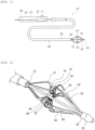
- the medical device 10 includes an elongated shaft portion 20, an expansion body 21 provided at a distal portion of the shaft portion 20, and an operation unit 23 provided at a proximal portion of the shaft portion 20.
- the expansion body 21 is provided with an electrode portion 61 that is an energy transfer element for performing the maintenance treatment described above.
- the shaft portion 20 includes a distal portion 30 including a proximal end fixing portion 31 to which a proximal end of the expansion body 21 is fixed and a distal end fixing portion 33 to which a distal end of the expansion body 21 is fixed.
- the distal portion 30 of the shaft portion 20 includes a shaft extension portion 32 extending inside the expansion body 21 from the proximal end fixing portion 31.
- the shaft portion 20 includes a housing sheath 25 provided on an outermost peripheral portion thereof.
- the expansion body 21 can move forward and backward in an axial direction with respect to the housing sheath 25.
- the housing sheath 25 can house the expansion body 21 therein while being moved to a distal side of the shaft portion 20.
- the expansion body 21 can be exposed when the housing sheath 25 is moved to a proximal side from a state of housing the expansion body 21.
- the shaft portion 20 includes a pulling shaft 26.
- the pulling shaft 26 is provided from the proximal end of the shaft portion 20 to the shaft extension portion 32, and a distal portion thereof is fixed to a distal member 35.
- the distal member 35 to which the distal portion of the pulling shaft 26 is fixed may not be fixed to the expansion body 21. Accordingly, the distal member 35 can pull the expansion body 21 in a compression direction. In addition, at the time of housing the expansion body 21 into the housing sheath 25, the expansion body 21 can be easily moved in an extension direction by separating the distal member 35 from the expansion body 21 to the distal side, and a housing property can be improved.
- the operation unit 23 includes a housing 40 to be gripped by an operator, an operation dial 41 that can be rotationally operated by the operator, and a conversion mechanism 42 that is operated in conjunction with the rotation of the operation dial 41.
- the pulling shaft 26 is held by the conversion mechanism 42 in an inside of the operation unit 23.
- the conversion mechanism 42 can move the held pulling shaft 26 forward and backward along the axial direction in conjunction with the rotation of the operation dial 41.
- a rack and pinion mechanism can be used as the conversion mechanism 42.
- the shaft portion 20 is preferably formed of a material having a certain degree of flexibility.
- a material having a certain degree of flexibility examples include polyolefins such as polyethylene, polypropylene, polybutene, an ethylene-propylene copolymer, an ethylene-vinyl acetate copolymer, an ionomer, or a mixture of two or more thereof; soft polyvinyl chloride resin; polyamide; polyamide elastomer; polyester; polyester elastomer; polyurethane; a fluorine resin such as polytetrafluoroethylene; polyimide; PEEK; silicone rubber; and latex rubber.
- the pulling shaft 26 can be formed, for example, by coating an elongated wire made of a metallic material such as stainless steel or a superelastic alloy such as a nickel-titanium alloy or a copper-zinc alloy, or made of a resin material having a relatively high rigidity with a resin material such as polyvinyl chloride, polyethylene, polypropylene or ethylene-propylene copolymer.
- a metallic material such as stainless steel or a superelastic alloy such as a nickel-titanium alloy or a copper-zinc alloy
- a resin material having a relatively high rigidity such as polyvinyl chloride, polyethylene, polypropylene or ethylene-propylene copolymer.
- the distal member 35 can be made of, for example, a polymeric material such as polyolefin, polyvinyl chloride, polyamide, polyamide elastomer, polyurethane, polyurethane elastomer, polyimide or fluororesin or a mixture thereof, or a multilayer tube of two or more kinds of polymeric materials.
- a polymeric material such as polyolefin, polyvinyl chloride, polyamide, polyamide elastomer, polyurethane, polyurethane elastomer, polyimide or fluororesin or a mixture thereof, or a multilayer tube of two or more kinds of polymeric materials.
- the expansion body 21 includes a plurality of wire portions 50 in a circumferential direction.
- four wire portions 50 are provided in the circumferential direction.
- Each of the wire portions 50 can expand and contract in a radial direction.
- a proximal end of the wire portion 50 is fixed to the proximal end fixing portion 31, and extends from the proximal end fixing portion 31 to the distal side.
- a distal end of the wire portion 50 is fixed to the distal end fixing portion 33, and extends from the distal end fixing portion 33 to the proximal side.
- the wire portion 50 is inclined so as to increase in the radial direction from both end portions in the axial direction toward a center portion.
- the wire portion 50 includes a recessed portion 51 that is recessed radially inward of the expansion body 21 at the central portion in the axial direction.
- a radially innermost portion of the recessed portion 51 is a bottom portion 52.
- the wire portion 50 includes a second through-hole 81 and a third through-hole 82 in a portion serving as the bottom portion 52, and includes a first engaging portion 83 serving as an electrode engaging portion between the second through-hole 81 and the third through-hole 82.
- a first through-hole 80 is formed on the proximal side of the second through-hole 81
- a fourth through-hole 84 is formed on the distal side of the third through-hole 82.
- a distal side of the bottom portion 52 includes a slit shape center portion in a width direction, and includes outer edge portions 58 on both sides and a back support portion 59 on the center portion.
- the wire portion 50 that forms the expansion body 21 has, for example, a flat plate shape cut out from a cylinder.
- the wire forming the expansion body 21 can have a thickness of 50 ⁇ m to 500 ⁇ m and a width of 0.3 mm to 2.0 mm. However, the wire may have a dimension outside this range.
- the wire portion 50 may have a circular cross-sectional shape or a cross-sectional shape other than the circular cross-sectional shape.
- the electrode assembly 22 separate from the expansion body 21 is attached to the expansion body 21.
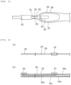
- the electrode assembly 22 includes an elongated wiring portion 60, the electrode portion 61 provided in an intermediate portion in a length direction of the wiring portion 60, and a connection portion 62 provided at a proximal portion of the wiring portion 60.
- the wiring portion 60 includes an electric wire portion 60a having conductivity.
- the electric wire portion 60a, the electrode portion 61, and the connection portion 62 can be made of a metal material.
- the electric wire portion 60a is embedded in an adhesive layer 60b sandwiched between insulating layers 60c provided on both surfaces of the wiring portion 60 in a thickness direction.
- the electrode portion 61 is provided so as to be exposed on a surface of the insulating layer 60c, and is electrically connected to the electric wire portion 60a.
- the connection portion 62 is a portion that electrically connects the electrode assembly 22 to a connection line (not illustrated) provided on the proximal side of the medical device 1, and similarly to the electrode portion 61, is exposed on the surface of the insulating layer 60c and electrically connected to the electric wire portion 60a.
- the electrode portion 61 is implemented by, for example, a bipolar electrode that receives electric energy from an energy supply device (not illustrated), which is an external device. In this case, energization is performed among the electrode portions 61 disposed on the wire portions 50.
- the electrode portion 61 and the energy supply device are connected by a conducting wire (not illustrated) covered with an insulating covering material. The conducting wire is led out to the outside through the shaft portion 20 and the operation unit 23, and is connected to the energy supply device.
- the electrode portion 61 may be implemented by a monopolar electrode. In this case, energization is performed from a counter electrode plate prepared outside a body.
- a heat generating element electrode tip
- energization is performed among the heat generating elements disposed in the wire portions 50.
- the electrode portion 61 may include an energy transfer element capable of applying energy to the puncture hole Hh, such as an element that performs heating or cooling by using microwave energy, ultrasound energy, coherent light such as laser, a heated fluid, a cooled fluid, or a chemical medium, an element that generates frictional heat, or a heater including an electric wire, and a specific form thereof is not specially limited.
- an energy transfer element capable of applying energy to the puncture hole Hh, such as an element that performs heating or cooling by using microwave energy, ultrasound energy, coherent light such as laser, a heated fluid, a cooled fluid, or a chemical medium, an element that generates frictional heat, or a heater including an electric wire, and a specific form thereof is not specially limited.
- the wire portion 50 can be made of a metal material.
- a metal material for example, a titanium-based (Ti-Ni, Ti-Pd, Ti-Nb-Sn, etc.) alloy, a copper-based alloy, stainless steel, ⁇ titanium steel, or a Co-Cr alloy can be used.
- An alloy having a spring property such as a nickel titanium alloy may be more preferably used.
- a material for the wire portion 50 is not limited thereto, and the wire portion 50 may be made of other materials.
- the electrode assembly 22 is fixed along a surface of the wire portion 50 by engaging and hooking the wiring portion 60 with a plurality of electrode engaging portions of the expansion body 21.
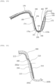
- the wire portion 50 includes the recessed portion 51 that is recessed radially inward and defines a receiving space 51a capable of receiving a biological tissue when the expansion body 21 is expanded.
- the wire portion 50 includes a proximal side curved portion 52a that is a proximal side portion of the bottom portion 52, which is on a radially innermost side of the recessed portion 51, and a distal side curved portion 52b that is a distal side portion of the bottom portion 52.
- the wire portion 50 includes a proximal side upright portion 53 extending radially outward from the proximal side curved portion 52a toward the proximal side, and a distal side upright portion 54 extending radially outward from the distal side curved portion 52b toward the distal side.
- the wire portion 50 includes a proximal side expansion portion 55 extending radially outward from the proximal end fixing portion 31 of the shaft portion 20 toward the distal side, and a distal side expansion portion 56 extending radially outward from the distal end fixing portion 33 of the shaft portion 20 toward the proximal side.
- the proximal side expansion portion 55 includes an outward curved portion 57 whose distal end is connected to an outer end of the proximal side upright portion 53, which is curved in a convex shape outward in the radial direction, and which deforms in response to expansion and contraction of the expansion body 21.
- the distal side expansion portion 56 includes an outward curved portion 57 whose proximal end is connected to an outer end of the distal side upright portion 54, is curved in a convex shape outward in the radial direction, and deforms in response to the expansion and contraction of the expansion body 21.
- the proximal side upright portion 53 includes the first through-hole 80, and a third engaging portion 80a serving as an electrode engaging portion that engages the electrode assembly 22 is formed by an edge portion of the proximal side upright portion 53.
- the proximal side curved portion 52a includes the second through-hole 81
- the distal side curved portion 52b includes the third through-hole 82
- the first engaging portion 83 serving as an electrode engaging portion is formed between the second through-hole 81 and the third through-hole 82.
- the first engaging portion 83 has a form in which both end portions in the width direction are bridged in the bottom portion 52 of the wire portion 50.
- the distal side upright portion 54 includes the fourth through-hole 84, and a second engaging portion 84a serving as an electrode engaging portion is formed by an edge portion of the distal side upright portion 54.
- the electrode assembly 22 includes an inner arrangement portion 70 extending along an inner side of the expansion body 21 from the distal portion 30 of the shaft portion 20 toward a distal direction to the first through-hole 80 via a vicinity of the outward curved portion 57 of the proximal side expansion portion 55.
- the inner arrangement portion 70 is separated from the outward curved portion 57 of the wire portion 50 when the expansion body 21 is expanded. Therefore, the electrode assembly 22 can be prevented from being damaged even when the outward curved portion 57 deforms when the expansion body 21 is expanded or contracted.
- the electrode assembly 22 includes an outer arrangement portion 71 extending from the first through-hole 80 to the bottom portion 52 of the recessed portion 51 so as to face the receiving space 51a along the expansion body 21.
- the electrode portion 61 is disposed on the outer arrangement portion 71 and faces the receiving space 51a.
- the electrode assembly 22 includes a first hook portion 72 that is hooked and engaged with the first engaging portion 83 by extending from an extension end of the outer arrangement portion 71, passing through the second through-hole 81, passing through the third through-hole 82 from a radially inner side of the first engaging portion 83, and extending to an outer side of the expansion body 21.
- the first hook portion 72 functions as an engaged portion that is engaged with the first engaging portion 83, which is an electrode engaging portion.
- the "extension end” indicates an end in an extending direction when each of the plurality of electrode assemblies 22 extends from the distal portion of the shaft portion 20 or the distal portion of the expansion body 21 along the expansion body 21.
- One of the plurality of electrode assemblies 22 may extend from the distal portion of the expansion body 21, and the other electrode assembly 22 may extend from the distal portion of the shaft portion 20.
- the electrode portion 61 is provided on the electrode assembly 22 that is separate from the wire portion 50 forming the expansion body 21, the electrode portion 61 can be disposed in a position close to the radially innermost bottom portion 52 of the recessed portion 51. In addition, since the electrode portion 61 is not fixed to the proximal side curved portion 52a and the distal side curved portion 52b that are deformed by the expansion and contraction of the expansion body 21 and is in a floating state, the electrode portion 61 can be prevented from being damaged due to the deformation of the expansion body 21.
- the electrode assembly 22 includes a second hook portion 73 that is engaged with the second engaging portion 84a by extending from an extension end of the first hook portion 72 and passing through the fourth through-hole 84 from the outer side to the inner side of the expansion body 21.
- the second hook portion 73 functions as an engaged portion that is engaged with the second engaging portion 84a, which is an electrode engaging portion.
- the second hook portion 73 includes a folded-back portion 73a passing through the fourth through-hole 84 and extending toward the bottom portion 52 inside the expansion body 21.
- the electrode assembly 22 is reliably fixed to the wire portion 50 by the second hook portion 73, and displacement of the electrode portion 61 can be prevented.
- the electrode assembly 22 includes a third hook portion 74 that is engaged with the first engaging portion 83 by extending from an extension end of the second hook portion 73, passing through the second through-hole 81 from the inner side of the expansion body 21, and extending to the outer side of the expansion body 21.
- the third hook portion 74 functions as an engaged portion that is engaged with the first engaging portion 83, which is an electrode engaging portion.
- the electrode assembly 22 includes a first extension portion 84 extending from an extension end of the third hook portion 74 and extending between the outer arrangement portion 71 and the proximal side upright portion 53 toward the first through-hole 80.
- the proximal side upright portion 53 and the first extension portion 84 are covered with a first cover 65.
- a heat-shrinkable tube or the like can be used as the first cover 65.
- the first cover 65 enables the electrode assembly 22 to reliably follow movement of the proximal side upright portion 53 when the expansion body 21 is expanded or contracted. Accordingly, the electrode assembly 22 can be prevented from contacting an unintended location and being damaged. In addition, since a portion of the electrode assembly 22 covered with the first cover 65 is slidable in a length direction, a local excessive deformation force can be prevented from being applied to the electrode assembly 22 when the expansion body 21 is expanded or contracted.
- the electrode assembly 22 includes a fourth hook portion 76 that is engaged with the third engaging portion 80a by extending from an extension end of the first extension portion 84 and passing through the first through-hole 80.
- the fourth hook portion 76 functions as an engaged portion that is engaged with the third engaging portion 80a, which is an electrode engaging portion.
- the fourth hook portion 76 includes a crank-shaped portion 76a extending from the extension end of the first extension portion 84, passing through the first through-hole 80, and extending along the inner side of the expansion body 21.
- the electrode assembly 22 includes a second extension portion 77 extending from an extension end of the crank-shaped portion 76a and extending along the inner arrangement portion 70 on a radially inner side of the inner arrangement portion 70.
- the second extension portion 77, the inner arrangement portion 70, and the proximal side expansion portion 55 are covered with a second cover 66.
- a heat-shrinkable tube or the like can be used as the second cover 66.
- the second cover 66 can also prevent the electrode assembly 22 from contacting an unintended location, and prevent a local excessive deformation force from being applied to the electrode assembly 22 when the expansion body 21 is expanded or contracted.
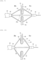
- the expansion body 21 housed in the housing sheath 25 is contracted in the radial direction.
- the expansion body 21 and the housing sheath 25 move in the axial direction relative to each other, the expansion body 21 is exposed to the outside of the housing sheath 25 and expands in the radial direction.
- the treatment method according to the present embodiment is performed on a patient suffering from heart failure (left heart failure). More specifically, as illustrated in FIG. 8 , the treatment method is performed on a patient suffering from a chronic heart failure, who has high blood pressure in a left atrium HLa due to myocardial hypertrophy appearing in a left ventricle of the heart H and increased stiffness (hardness).
- the treatment method includes a step (S1) of forming the puncture hole Hh in the atrial septum HA, a step (S2) of disposing the expansion body 21 in the puncture hole Hh, a step (S3) of expanding a diameter of the puncture hole Hh by the expansion body 21, a step (S4) of confirming hemodynamics in a vicinity of the puncture hole Hh, a step (S5) of performing the maintenance treatment for maintaining the size of the puncture hole Hh, and a step (S6) of confirming the hemodynamics in the vicinity of the puncture hole Hh after the maintenance treatment is performed.
- the operator delivers an introducer 310 in which a guiding sheath and a dilator are combined to a vicinity of the atrial septum HA.
- the introducer 310 can be delivered to a right atrium HRa via an inferior vena cava Iv.
- the introducer can be delivered using a guide wire 11.
- the operator can insert the guide wire 11 into the dilator and deliver the introducer along the guide wire 11.
- the introducer and the guide wire 11 can be inserted into a living body using a known method such as using an introducer for blood vessel introduction.
- step S1 the operator causes a puncture device (not illustrated) to penetrate from a right atrium HRa side toward a left atrium HLa side to form the puncture hole Hh.
- a puncture device such as a wire having a sharp distal end can be used as the puncture device.
- the puncture device is inserted into the dilator and delivered to the atrial septum HA. After the guide wire 11 is removed from the dilator, the puncture device can be delivered to the atrial septum HA in place of the guide wire 11.
- step S2 first, the medical device 10 is delivered to the vicinity of the atrial septum HA along the guide wire 11 inserted in advance. At this time, the distal portion of the medical device 10 penetrates the atrial septum HA and reaches the left atrium HLa. In addition, when the medical device 10 is inserted, the expansion body 21 is in a state of being housed in the housing sheath 25.
- the expansion body 21 is exposed by moving the housing sheath 25 to the proximal side. Accordingly, the expansion body 21 is expanded in diameter, the recessed portion 51 is disposed in the puncture hole Hh of the atrial septum HA, and a biological tissue surrounding the puncture hole Hh is received in the receiving space 51a. Accordingly, the biological tissue is sandwiched between the proximal side upright portion 53 on which the electrode portion 61 is provided and the distal side upright portion 54.
- step S3 the operator operates the operation unit 23 in a state in which the receiving space 51a receives the biological tissue, and moves the pulling shaft 26 to the proximal side. Accordingly, as illustrated in FIG. 10 , the expansion body 21 is further expanded in the radial direction, and the puncture hole Hh is expanded in the radial direction.
- the hemodynamics is confirmed in step S4.
- the operator delivers a hemodynamics confirming device 320 to the right atrium HRa via the inferior vena cava Iv.
- a known echo catheter can be used as the hemodynamics confirming device 320.
- the operator can display an echo image acquired by the hemodynamics confirming device 320 on a display device such as a display, and confirm a blood volume passing through the puncture hole Hh based on a display result.
- step S5 the operator performs the maintenance treatment in order to maintain the size of the puncture hole Hh.
- the maintenance treatment by applying high-frequency energy to the edge portion of the puncture hole Hh by the electrode portion 61, an edge portion of the puncture hole Hh is cauterized (heated and cauterized) by the high-frequency energy.
- the puncture hole Hh When the biological tissue in a vicinity of the edge portion of the puncture hole Hh is cauterized by the electrode portion 61, a degenerated portion having a degenerated biological tissue is formed in the vicinity of the edge portion. Since the biological tissue in the degenerated portion loses elasticity, the puncture hole Hh can maintain a shape when being expanded by the expansion body 21.
- step S6 After the maintenance treatment, the hemodynamics is confirmed again in step S6, and when a blood volume passing through the puncture hole Hh is a desired volume, the operator contracts the expansion body 21 in diameter, stores the expansion body 21 in the housing sheath 25, and then removes the expansion body 21 from the puncture hole Hh. Further, the entire medical device 10 is removed to the outside of the living body, and the treatment is ended.
- a wire portion 101 of an expansion body 100 includes a proximal side curved portion 103a and a distal side curved portion 103b at a bottom portion 103 of a recessed portion 102.
- a second through-hole 121 is formed in the distal side curved portion 103b
- a third through-hole 122 is formed in the proximal side curved portion 103a
- a first engaging portion 123 is formed between the second through-hole 121 and the third through-hole 122.
- the first engaging portion 123 is disposed slightly closer to the proximal side at the bottom portion 103 of the recessed portion 102.
- a first through-hole 120 is formed in a proximal side upright portion 104 of the wire portion 101.
- An electrode assembly 110 includes an inner arrangement portion 113 on the proximal side of the first through-hole 120 and an outer arrangement portion 114 on the distal side of the first through-hole 120.
- An electrode portion 112 is disposed on the outer arrangement portion 114 so as to face a receiving space 102b.
- the electrode assembly 110 includes a first hook portion 115 that is engaged with the first engaging portion 123 by extending from an extension end of the outer arrangement portion 114, passing through the second through-hole 121 of the distal side curved portion 103b passing through the third through-hole 122 of the proximal side curved portion 103a from a radially inner side of the first engaging portion 123, and extending to an outer side of the expansion body 100. Since the first engaging portion 123 is disposed closer to the proximal side of the bottom portion 102a, the electrode portion 112 can be disposed along the proximal side upright portion 104.
- a wiring portion 111 includes a first extension portion 116 extending from an extension end of the first hook portion 115 and extending between the outer arrangement portion 114 and the proximal side upright portion 104 toward the first through-hole 120. Further, the wiring portion 111 includes a fourth hook portion 117 that extends from an extension end of the first extension portion 116 and passes through the first through-hole 120 to engage with a fourth engaging portion 120a formed at an edge portion of the first through-hole 120. In this manner, the electrode assembly 110 may be folded back at the first engaging portion 123 formed at the bottom portion 102a of the recessed portion 102.
- a wire portion 131 of the expansion body 130 includes a recessed portion 132.
- a second through-hole 151 is formed in a bottom portion 133 of the recessed portion 132.
- a first engaging portion 152 is formed at an edge portion of the second through-hole 151.
- the electrode assembly 140 includes an inner arrangement portion 143 on a proximal side of a first through-hole 150 and an outer arrangement portion 144 on a distal side of the first through-hole 150.
- An electrode portion 142 is disposed on the outer arrangement portion 114 so as to face a receiving space 132a.
- a wiring portion 141 includes a first hook portion 145 that extends from an extension end of the outer arrangement portion 114, passes through the second through-hole 151, and extends to a radially inner side of the bottom portion 133. As illustrated in (b) of FIG.
- the first hook portion 145 includes a wide portion 145a that is wider than a passing portion 145b of the first hook portion 145 passing through the second through-hole 151 and is engaged with the first engaging portion 152.
- the electrode assembly 140 may use the wide portion 145a provided at the distal portion as an engaged portion.
- a fixing structure of the first hook portion 145 including the wide portion 145a may be in another form.
- the expansion body 130 includes a second through-hole 155 in a proximal side curved portion 133a and a third through-hole 156 in a distal side curved portion 133b, and a first engaging portion 157 is formed between the second through-hole 155 and the third through-hole 156.
- the first hook portion 145 is engaged with the first engaging portion 157 by extending from an extension end of the outer arrangement portion 144, passing through the second through-hole 155, passing through the third through-hole 156 from a radially inner side of the first engaging portion 157, and extending to an outer side of the expansion body 130.
- the wide portion 145a of the first hook portion 145 is hooked and engaged with a second engaging portion 156a formed at an edge portion of the third through-hole 156.
- the expansion body 130 may include a fourth through-hole 158 in a distal side upright portion 135, and a second engaging portion 158a may be formed at an edge portion of the fourth through-hole 158.
- the first hook portion 145 passing through the second through-hole 155 may be engaged with the second engaging portion 158a at the wide portion 145a by extending to the fourth through-hole 158.
- a configuration of the expansion body 170 is similar to that in FIG. 6 , and the expansion body 170 includes a first through-hole 190 in a proximal side upright portion 174, a second through-hole 191 in a proximal side curved portion 173a, a third through-hole 192 in a distal side curved portion 173b, and a fourth through-hole 194 in a distal side upright portion 175.
- the expansion body 170 includes, as electrode engaging portions, a first engaging portion 193 formed between the second through-hole 191 and the third through-hole 192 of a bottom portion 173, and a second engaging portion 194a formed at an edge portion of the fourth through-hole 194.
- the electrode assembly 180 includes a first hook portion 185 that is engaged with the first engaging portion 193 by extending from an extension end of an outer arrangement portion 184, passing through the second through-hole 191, passing through the third through-hole 192 from a radially inner side of the first engaging portion 193, and extending to an outer side of the expansion body 170.
- the electrode assembly 180 includes a second hook portion 187 that is engaged with the second engaging portion 194a by extending from an extension end of the first hook portion 185 and passing through the fourth through-hole 194 from an outer side to an inner side of the expansion body 170.
- An electrode portion 182 is disposed between the first hook portion 185 and the second hook portion 187. Therefore, the electrode portion 182 is disposed along the distal side upright portion 175 of a recessed portion 172. In this manner, the electrode portion 182 may be disposed on a distal side of the recessed portion 172.
- the expansion body 200 includes a first through-hole 205 in a proximal side upright portion 204.
- the electrode assembly 210 includes an inner arrangement portion 213 and an outer arrangement portion 214 with the first through-hole 205 sandwiched therebetween, and the outer arrangement portion 214 is disposed along the proximal side upright portion 204.
- An electrode portion 212 is disposed on the outer arrangement portion 214. The electrode portion 212 faces a receiving space 202a, and a back side of the electrode portion 212 is bonded and fixed to the expansion body 200 by a bonding portion 215.
- the bonding portion 215 is provided in a radially outer region of the electrode portion 212, and does not reach a proximal side curved portion 203a and a distal side curved portion 203b of the expansion body 200. Therefore, the outer arrangement portion 214 on which the electrode portion 212 is disposed is in a floating state with respect to the proximal side curved portion 203a and the distal side curved portion 203b.
- the electrode assembly 200 may be fixed by bonding, and in this case, the electrode portion 212 can extend to a vicinity of a bottom portion 203 by forming the bonding portion 215 such that the electrode portion 212 is in a floating state with respect to the proximal side curved portion 203a and the distal side curved portion 203b.
- the expansion body 220 includes a first through-hole 226 in a distal side upright portion 225.
- the electrode assembly 230 includes an inner arrangement portion 233 extending from the distal portion 30 of the shaft portion 20 to the first through-hole 226 of the distal side upright portion 230 passing a proximal side upright portion 224 along an inner side of the expansion body 220.
- the expansion body 220 includes an outer arrangement portion 234 extending from the first through-hole 226 to a bottom portion 223 along the expansion body 220 so as to be folded back with respect to the inner arrangement portion 233 and face a receiving space 222a.
- An electrode portion 232 is disposed along the outer arrangement portion 234, and is fixed to the outer arrangement portion 234 by a bonding portion 235.
- the bonding portion 235 does not to reach a proximal side curved portion 223a and a distal side curved portion 223b, and a region of the outer arrangement portion 234 in which the electrode portion 232 is disposed on a bottom portion 223 side is in a floating state with respect to the proximal side curved portion 223a and the distal side curved portion 223b.
- the inner arrangement portion 233 may be long, and the electrode portion 232 may be disposed along the distal side upright portion 225.
- the fixation of the electrode assembly 230 is not limited to bonding, and the electrode assembly 230 may be fixed by the plurality of electrode engaging portions described above.
- a distal side upright portion 245 of the expansion body 240 includes a first through-hole 246.
- the electrode assembly 250 includes a shaft arrangement portion 253 extending from the proximal end fixing portion 31 of the shaft portion 20 to the distal end fixing portion 33 along the shaft extension portion 32.
- the electrode assembly 250 includes an inner arrangement portion 254 extending along an inner side of the expansion body 240 from an extension end of the shaft arrangement portion 253 to the first through-hole 246 passing a vicinity of an outward curved portion 248 of a distal side expansion portion 247, and an outer arrangement portion 255 extending along the expansion body 240 from the first through-hole 246 to a vicinity of a bottom portion 243 so as to face a receiving space 242a.
- the inner arrangement portion 254 is separated from the outward curved portion 248 of the distal side expansion portion 247 when the expansion body 240 is expanded.
- the outer arrangement portion 255 on which an electrode portion 252 is disposed is bonded and fixed to the expansion body 240 by a bonding portion 256.
- the bonding portion 256 does not to reach a proximal side curved portion 243a and a distal side curved portion 243b, and a region of the outer arrangement portion 255 on a bottom portion 243 side is in a floating state with respect to the proximal side curved portion 243a and the distal side curved portion 243b.
- the electrode assembly 250 may include a portion along the shaft portion 20.
- the fixation of the electrode assembly 250 is not limited to bonding, and the electrode assembly 250 may be fixed by the plurality of electrode engaging portions described above.
- the expansion body 260 is formed of a mesh obtained by braiding many wires 261.
- the expansion body 260 includes a recessed portion 262, and an electrode portion 272 is disposed on a proximal side upright portion 264.
- the electrode assembly 270 is engaged with the expansion body 260 by being inserted into a space between the wires 261.
- the electrode assembly 270 includes a first hook portion 274 engaged with a bottom portion 263, a second hook portion 275 engaged with a distal side upright portion 265, a third hook portion 276 that passes through a radially inner side of the first hook portion 274 to engage with the bottom portion 263, and a fourth hook portion 277 engaged with the proximal side upright portion 264.
- an outer arrangement portion 273 on which the electrode portion 272 is disposed faces a receiving space 262a, and is in a floating state with respect to the bottom portion 263.
- the electrode assembly 270 can be fixed along an outer shape of the expansion body 260 formed of a mesh.
- the fixation of the electrode assembly 270 is not limited to this modification, and any one of the fixation based on the plurality of electrode engaging portions described above may be applied.
- the expansion body may be different from the expansion body 21 in which the plurality of wire portions 50 are fixed to the proximal end fixing portion 31 and the distal end fixing portion 33 of the shaft portion 20, and the expansion body 260 formed of a mesh as described above.
- an expansion body including a plurality of wire portions may include a proximal side expansion portion and a distal side expansion portion, the proximal side expansion portion may be fixed to a proximal end fixing portion of a shaft portion, and the distal side expansion portion may not be bundled and fixed.
- the expansion body including a plurality of wire portions may include a proximal side expansion portion fixed to a proximal end fixing portion, and may not include a distal side expansion portion.
- the electrode assembly may include a wide portion that is wider than an electrode engaging portion of the expansion body at an end or an intermediate position in the extending direction serving as an engaged portion.
- the fourth hook portion 76 may be provided with a wide portion to serve as an end of the electrode assembly 22.
- wide portions may be provided at portions of the second hook portion 73 forward and rearward of a portion passing through the fourth through-hole 84 so as to be engaged with the second engaging portion 84a.
- the plurality of electrode assemblies 22 may have different fixing structures.
- a structure of the electrode assembly 22 illustrated in FIG. 6 can be employed for two of four wire portions 50, and a structure of the electrode assembly 180 illustrated in FIG. 15 can be employed for the remaining two wire portions 50.
- the electrode assemblies 22 may employ other combinations other than the above.
- the medical device 10 includes the expansion body 21 configured to expand and contract in a radial direction, the elongated shaft portion 20 including the distal portion 30 that includes the proximal end fixing portion 31 to which a proximal end of the expansion body 21 is fixed, and the plurality of electrode assemblies 22 extending from the proximal end fixing portion 31 of the shaft portion 20 along at least a part of the expansion body 21.
- the expansion body 21 includes the recessed portion 51 that is recessed radially inward and that defines the receiving space 51a capable of receiving a biological tissue when the expansion body 21 is expanded.
- the recessed portion 51 includes the radially innermost bottom portion 52 including the proximal side curved portion 52a and the distal side curved portion 52b, the proximal side upright portion 53 extending radially outward from the proximal side curved portion 52a, and the distal side upright portion 54 extending radially outward from the distal side curved portion 52b.
- Each of the plurality of electrode assemblies 22 includes the electrode portion 61 disposed along the expansion body 21 from the proximal side upright portion 53 or the distal side upright portion 54 to the bottom portion 52 so as to face the receiving space 51a.
- the proximal side curved portion 52a and the distal side curved portion 52b deform in response to expansion and contraction of the expansion body 21.
- the electrode portion 61 is in a floating state with respect to the distal side curved portion 52b and the proximal side curved portion 52a.
- the electrode portion 61 since the electrode portion 61 is provided on the electrode assembly 22 separate from the expansion body 21, the electrode portion 61 can be disposed in a position close to the radially innermost bottom portion 52 of the recessed portion 51.
- the electrode portion 61 since the electrode portion 61 is not fixed to the proximal side curved portion 52a and the distal side curved portion 52b that are deformed by the expansion and contraction of the expansion body 21 and is in a floating state, the electrode portion 61 disposed at a position close to the bottom portion 52 can be prevented from being damaged due to the deformation of the expansion body 21.
- the expansion body 21 may include a plurality of electrode engaging portions configured to engage each of the plurality of electrode assemblies 22 with the expansion body 21.
- Each of the plurality of electrode assemblies 22 may include an engaged portion that is engaged with a corresponding one of the electrode engaging portions.
- Each of the electrode engaging portions may be provided in at least one of the bottom portion 52, the proximal side upright portion 52a, and the distal side upright portion 52b. Accordingly, since the electrode assemblies are engaged and fixed to the plurality of electrode engaging portions of the expansion body 21, the electrode portion 61 can be fixed to the expansion body 21 so as not to be displaced.
- the expansion body 21 may include the proximal side expansion portion 55 extending radially outward from the proximal end fixing portion 31 of the shaft portion 20 toward a distal direction.
- the proximal side expansion portion 55 may include the outward curved portion 57 whose distal end is connected to an outer end of the proximal side upright portion 53 and which is curved in a convex shape outward in the radial direction.
- the proximal side upright portion 53 may include the first through-hole 80 penetrating the expansion body 21.
- At least one of the plurality of electrode assemblies 22 may include the inner arrangement portion 70 extending along an inner side of the expansion body 21 from the distal portion 30 of the shaft portion 20 to the first through-hole 80 via a vicinity of the outward curved portion 57 of the proximal side expansion portion 55, and the outer arrangement portion 71 extending along the expansion body 21 from the first through-hole 80 to at least the bottom portion 52 so as to face the receiving space 51a.
- the outward curved portion 57 of the proximal side expansion portion 55 may deform in response to the expansion and contraction of the expansion body 21.
- the inner arrangement portion 70 may be separated from the outward curved portion 57 of the proximal side expansion portion 53 at least when the expansion body 21 is expanded.
- the outer arrangement portion 71 may be in a floating state with respect to the distal side curved portion 52b and the proximal side curved portion 51a. Accordingly, the electrode assembly 22 can be prevented from interfering with the expansion body 21 and being damaged.
- the expansion body 21 may include the second through-hole 81 in the proximal side curved portion 52a and the third through-hole 82 in the distal side curved portion 52b.
- the plurality of electrode engaging portions may include the first engaging portion 83 between the second through-hole 81 and the third through-hole 82 of the bottom portion 52.
- the at least one of the plurality of electrode assemblies 22 may include the first hook portion 72 that functions as the engaged portion, the first hook portion 72 being engaged with the first engaging portion 83 by extending from an extension end of the outer arrangement portion 71, passing through the second through-hole 81, passing through the third through-hole 82 from a radially inner side of the first engaging portion 83, and extending to an outer side of the expansion body 21. Accordingly, the electrode portion 61 is disposed close to the bottom portion 52 of the expansion body 21, the electrode assembly 22 can follow the expansion and contraction of the expansion body 21, and the electrode assembly 22 and the expansion body 21 can be prevented from rubbing against each other and being damaged.
- the expansion body 21 may include the fourth through-hole 84 in the distal side upright portion 54.
- the plurality of electrode engaging portions may include the second engaging portion 84a formed from an edge portion of the fourth through-hole 84.
- the at least one of the plurality of electrode assemblies 22 may include the second hook portion 73 that functions as the engaged portion, the second hook portion 73 being engaged with the second engaging portion 84a by extending from an extension end of the first hook portion 72 and passing through the fourth through-hole 84 from the outer side to the inner side of the expansion body 21. Accordingly, the electrode assembly 22 can be more strongly fixed to the expansion body 21, and displacement of the electrode portion 61 can be prevented.
- the second hook portion 73 may include the folded-back portion 73a passing through the fourth through-hole 84 and extending toward the bottom portion 52 inside the expansion body 21. Accordingly, the electrode assembly 22 can be more reliably fixed to the expansion body 21.
- the at least one of the plurality of electrode assemblies 22 may include the third hook portion 74 that functions as the engaged portion, the third hook portion 74 being engaged with the first engaging portion 83 by extending from an extension end of the second hook portion 73, passing through the second through-hole 81 from the inner side of the expansion body 21, and extending to the outer side of the expansion body 21. Accordingly, since the electrode assembly 22 can be fixed to the expansion body 21 at a portion further extending to the distal side of the electrode portion 61, the displacement of the electrode portion 61 can be more effectively prevented.
- the at least one of the plurality of electrode assemblies 22 may include the first extension portion 75 extending from an extension end of the third hook portion 74 and extending between the outer arrangement portion 71 and the proximal side upright portion 53 toward the first through-hole 80.
- the medical device 10 may further include the first cover 65 configured to cover the proximal side upright portion 53 and the first extension portion 75. Accordingly, when the expansion body 21 is expanded or contracted, the electrode assembly 22 can reliably follow movement of the proximal side upright portion 53, and the electrode assembly 22 can be prevented from contacting an unintended location and being damaged.
- the at least one of the plurality of electrode assemblies 22 may include the electrode portion 61 on the outer arrangement portion 71.
- the first cover 65 may be sandwiched between the outer arrangement portion 71 and the first extension portion 75. Accordingly, the electrode assembly 22 can follow the expansion and contraction of the expansion body 21 while exposing the electrode portion 61 to an outside of the first cover 65.
- the plurality of electrode engaging portions may include the third engaging portion 80a formed from an edge portion of the first through-hole 80.
- the at least one of the plurality of electrode assemblies 22 may include the first extension portion 75 extending from an extension end of the third hook portion 74 and extending between the outer arrangement portion 71 and the proximal side upright portion 53 toward the first through-hole 80, and the fourth hook portion 76 that functions as the engaged portion, the fourth hook portion 76 being engaged with the third engaging portion 80a by extending from an extension end of the first extension portion 75 and passing through the first through-hole 80. Accordingly, the electrode assembly 22 can be more reliably fixed to the expansion body 21, and the displacement of the electrode portion 61 can be prevented.
- the fourth hook portion 76 may include the crank-shaped portion 76a extending from the extension end of the first extension portion 75, passing through the first through-hole 80 and extending along the inner side of the expansion body 21. Accordingly, the electrode assembly 22 can be more reliably engaged with the expansion body 21.
- the at least one of the plurality of electrode assemblies 22 may include the second extension portion 77 extending from an extension end of the crank-shaped portion 76a and extending along the inner arrangement portion 70 on a radially inner side of the inner arrangement portion 70.
- the medical device 10 may further include the second cover 66 configured to cover the second extension portion 77, the inner arrangement portion 70, and the proximal side expansion portion 55. Accordingly, since the electrode assembly 22 can be moved to follow the proximal side expansion portion 55 when the expansion body 21 is expanded or contracted, the electrode assembly 22 can be prevented from contacting an unintended location and being damaged.
- the expansion body 130 may include the second through-hole 151 in the bottom portion 133.
- the plurality of electrode engaging portions may include the first engaging portion 152 formed from an edge portion of the second through-hole 151.
- At least one of the plurality of electrode assemblies 140 may include the first hook portion 145 that functions as the engaged portion, the first hook portion 145 extending from an extension end of the outer arrangement portion 144, passing through the second through-hole 155, and extending to a radially inner side of the bottom portion 133.
- the first hook portion 145 may include the wide portion 145a that is wider than a portion of the first hook portion 145 passing through the second through-hole 151 and is engaged with the first engaging portion 152. Accordingly, the electrode portion 142 is disposed close to the bottom portion 133 of the expansion body 130, the electrode assembly 140 can follow expansion and contraction of the expansion body 130, and the electrode assembly 140 and the expansion body 130 can be prevented from rubbing against each other and being damaged.
- the plurality of electrode engaging portions may include the second engaging portion 156a formed from an edge portion of the third through-hole 156.
- the first hook portion 145 may include the wide portion 145a that is wider than a portion of the first hook portion 145 passing through the third through-hole 156 and is engaged with the second engaging portion 156a. Accordingly, since the electrode assembly 140 is engaged with the second engaging portion 156a by the wide portion 145a while being engaged with the first engaging portion 157, the electrode assembly 140 can be more reliably fixed to the expansion body 130.
- the expansion body 130 may include the second through-hole 155 in the proximal side curved portion 133a and the fourth through-hole 158 in the distal side upright portion 134.
- the plurality of electrode engaging portions may include the first engaging portion 157 formed from an edge portion of the second through-hole 155 and the second engaging portion 158a formed from an edge portion of the fourth through-hole 158.
- the at least one of the plurality of electrode assemblies 140 may include the first hook portion 145 that functions as the engaged portion, the first hook portion 145 being engaged with the first engaging portion 157 by extending from an extension end of the outer arrangement portion 144, passing through the second through-hole 155, passing through the fourth through-hole 158 from a radially inner side of the first engaging portion 157, and extending to an outer side of the expansion body 130.
- the first hook portion 145 may include the wide portion 145a that is wider than a portion of the first hook portion 145 passing through the fourth through-hole 158 and is engaged with the second engaging portion 158a. Accordingly, since the electrode assembly 140 can further extend to a distal side of the electrode portion 142 and fixed to the expansion body 130, displacement of the electrode portion 142 can be more effectively prevented.
- the expansion body 100 may include the second through-hole 121 in the distal side curved portion 103b and the third through-hole 122 in the proximal side curved portion 103a.
- the plurality of electrode engaging portions may include the first engaging portion 123 formed between the second through-hole 121 and the third through-hole 122 and the fourth engaging portion 120a formed from an edge portion of the first through-hole 120.
- At least one of the plurality of electrode assemblies 110 may include the first hook portion 115 that functions as the engaged portion, the first hook portion 115 being engaged with the first engaging portion 123 by extending from an extension end of the outer arrangement portion 114, passing through the second through-hole 121, passing through the third through-hole 122 from a radially inner side of the first engaging portion 123, and extending to an outer side of the expansion body 100, the first extension portion 116 extending from an extension end of the first hook portion 115 and extending between the outer arrangement portion 114 and the proximal side upright portion 104 toward the first through-hole 120, and the fourth hook portion 117 that functions as the engaged portion, the fourth hook portion 117 being engaged with the fourth engaging portion 120a by extending from an extension end of the first extension portion 116 and passing through the first through-hole 120. Accordingly, the electrode assembly 110 can be engaged and fixed at two locations, that is, the first engaging portion 123 and the fourth engaging portion 102a, and the electrode portion can be fixed with a simple structure.
- At least one of the plurality of electrode assemblies 210 may be bonded and fixed to the expansion body 200 at the proximal side upright portion 204 or the distal side upright portion. Accordingly, the electrode portion 212 can be fixed to the expansion body 200 while making a portion of the electrode portion 212 on the bottom portion 203 side in a floating state with respect to the expansion body 200.
- the expansion body 220 may include the first through-hole 226 in the distal side upright portion 225.
- At least one of the plurality of electrode assemblies 230 may include the inner arrangement portion 233 extending along an inner side of the expansion body 220 from the distal portion 30 of the shaft portion 20 to the first through-hole 226 of the distal side upright portion 225 beyond the proximal side upright portion 224, and an outer arrangement portion 234 folded back with respect to the inner arrangement portion 233 and extending along the expansion body 220 from the first through-hole 226 to the bottom portion 223 so as to face the receiving space 222a. Accordingly, the electrode portion 232 can be disposed on a distal side upright portion 225 side with a simple structure.
- the shaft portion 20 may include the shaft extension portion 32 extending inside the expansion body 240 along a central axis of the expansion body 240 from the proximal end fixing portion 31 and the distal end fixing portion 33 to which a distal end of the expansion body 240 is fixed.
- the expansion body 240 may include the distal side expansion portion 247 extending radially outward from the distal end fixing portion 33 of the shaft portion 20 toward a proximal direction.
- the distal side expansion portion 247 may include the outward curved portion 248 whose proximal end is connected to an outer end of the distal side upright portion 245 and which is curved in a convex shape outward in the radial direction.
- the distal side upright portion 245 may include the first through-hole 246.
- At least one of the plurality of electrode assemblies 250 may include the shaft arrangement portion 253 extending along the shaft extension portion 32 from the proximal end fixing portion 31 of the shaft portion 20 to the distal end fixing portion 33, the inner arrangement portion 254 extending along the inner side of the expansion body 240 from an extension end of the shaft arrangement portion 253 to the first through-hole 246 via a vicinity of the outward curved portion 248 of the distal side expansion portion 247, and the outer arrangement portion 255 extending along the expansion body 240 from the first through-hole 246 to at least the bottom portion 243 so as to face the receiving space 242a.
- the outward curved portion 248 of the distal side expansion portion 247 may deform in response to expansion and contraction of the expansion body 240.
- the inner arrangement portion 254 may be separated from the outward curved portion 248 of the distal side expansion portion 247 at least when the expansion body 240 is expanded.
- the outer arrangement portion 255 may be in a floating state with respect to the distal side curved portion 243b and the proximal side curved portion 243a. Accordingly, the electrode assembly 250 can be disposed while using the shaft portion 20, and the electrode assembly 250 can be made less likely to interfere with the expansion and contraction of the expansion body 240.
- the expansion body 170 may include the second through-hole 191 in the proximal side curved portion 173a, the third through-hole 192 in the distal side curved portion 173b, and the fourth through-hole 194 in the distal side upright portion 175.
- the plurality of electrode engaging portions may include the first engaging portion 193 formed between the second through-hole 191 and the third through-hole 192 of the bottom portion 173 and the second engaging portion 194a formed at an edge portion of the fourth through-hole 194.
- At least one of the plurality of electrode assemblies 180 may include the first hook portion 185 that functions as the engaged portion, the first hook portion 185 being engaged with the first engaging portion 193 by extending from an extension end of the outer arrangement portion 184, passing through the second through-hole 191, passing through the third through-hole 192 from a radially inner side of the first engaging portion 193, and extending to an outer side of the expansion body 170, and the second hook portion 187 that functions as the engaged portion, the second hook portion 187 being engaged with the second engaging portion 194a by extending from an extension end of the first hook portion 185 and passing through the fourth through-hole 194 from the outer side to an inner side of the expansion body 170.
- the electrode portion 182 may be disposed between the first hook portion 185 and the second hook portion 187. Accordingly, when the electrode portion 182 is disposed on a distal side upright portion 175 side, the electrode assembly 180 can be firmly engaged and fixed to the expansion body 170, and displacement of the electrode portion 182 can be prevented.
- the expansion body 260 may be formed of a mesh obtained by braiding many wires 261. At least one of the plurality of electrode assemblies 270 may be inserted between the wires 261 and engaged and fixed. Accordingly, the electrode assembly 270 can also be fixed to the expansion body 260 formed of a mesh, and the electrode portion 272 can be disposed in a vicinity of the bottom portion 263 of the recessed portion 262.
Landscapes
- Health & Medical Sciences (AREA)
- Life Sciences & Earth Sciences (AREA)
- Surgery (AREA)
- Engineering & Computer Science (AREA)
- Plasma & Fusion (AREA)
- Medical Informatics (AREA)
- Otolaryngology (AREA)
- Physics & Mathematics (AREA)
- Cardiology (AREA)
- Biomedical Technology (AREA)
- Heart & Thoracic Surgery (AREA)
- Nuclear Medicine, Radiotherapy & Molecular Imaging (AREA)
- Molecular Biology (AREA)
- Animal Behavior & Ethology (AREA)
- General Health & Medical Sciences (AREA)
- Public Health (AREA)
- Veterinary Medicine (AREA)
- Surgical Instruments (AREA)
Abstract
Description
- The present invention relates to a medical device that applies energy to a biological tissue.
- Chronic heart failure is one of known heart diseases. Chronic heart failure is broadly classified into a systolic heart failure and a diastolic heart failure, based on a cardiac function index. In a patient suffering from the diastolic heart failure, myocardial hypertrophy appears, and stiffness (hardness) increases, so that blood pressure increases in a left atrium, and a cardiac pumping function is degraded. Accordingly, the patient shows heart failure symptoms such as a pulmonary edema. In addition, there is another heart disease of a patient who shows the heart failure symptom because blood pressure increases on a right atrium side due to pulmonary hypertension, and the cardiac pumping function is degraded.
- In recent years, shunt treatments have attracted attention in which, for the patients who suffer from heart failure, a shunt (through-hole) serving as an escape route for increased atrial pressure is formed in an atrial septum, thereby enabling heart failure symptoms to be alleviated. In the shunt treatment, the atrial septum is accessed using an intravenous approaching method, and the through-hole is formed to have a desired size. For example, a medical device disclosed in PTL 1 is used as a medical device for performing the shunt treatment on the atrial septum.
- PTL 1:
WO2019/85841 - In the medical device of PTL 1, an electrode portion is fixed to a recessed portion of an expansion body. Since a vicinity of a bottom portion of the recessed portion largely deforms when the expansion body is expanded or contracted in a radial direction, it is difficult to dispose the electrode portion in the vicinity of the bottom portion. When the electrode portion is disposed at a position away from the bottom portion of the recessed portion, there is a possibility that an edge portion of the through-hole of the atrial septum cannot be sufficiently heated and cauterized when high frequency energy is applied from the electrode portion to the through-hole. In a case where the edge portion of the through-hole is not sufficiently cauterized, a through-hole having a desired size cannot be obtained after the cauterization.
- The invention is made to solve the above-described problems, and an object thereof is to provide a medical device in which an electrode portion provided in an expansion body can be disposed at a position close to a bottom portion of a recessed portion.
- A medical device according to the invention for achieving the above object includes an expansion body configured to expand and contract in a radial direction; an elongated shaft portion including a distal portion that includes a proximal end fixing portion to which a proximal end of the expansion body is fixed; and a plurality of electrode assemblies extending from the proximal end fixing portion of the shaft portion along at least a part of the expansion body. The expansion body includes a recessed portion that is recessed radially inward and that defines a receiving space to be configured to receive a biological tissue when the expansion body is expanded. The recessed portion includes a radially innermost bottom portion including a proximal side curved portion and a distal side curved portion, a proximal side upright portion extending radially outward from the proximal side curved portion, and a distal side upright portion extending radially outward from the distal side curved portion. Each of the plurality of electrode assemblies includes an electrode portion disposed along the expansion body from the proximal side upright portion or the distal side upright portion to the bottom portion so as to face the receiving space. The proximal side curved portion and the distal side curved portion are configured to deform in response to expansion and contraction of the expansion body. The electrode portion is in a floating state with respect to the distal side curved portion and the proximal side curved portion.
- In the medical device configured as described above, since the electrode portion is provided on the electrode assembly separate from the expansion body, the electrode portion can be disposed at a position close to the radially innermost bottom portion of the recessed portion. Since the electrode portion is not fixed to the proximal side curved portion and the distal side curved portion that deform in response to the expansion and contraction of the expansion body and is in a floating state, the electrode portion disposed at the position close to the bottom portion can be prevented from being damaged due to the deformation of the expansion body.
- The expansion body may include a plurality of electrode engaging portions that each engage one of the plurality of electrode assemblies with the expansion body. Each of the plurality of electrode assemblies may include an engaged portion that is engaged with a corresponding one of the electrode engaging portions. Each of the electrode engaging portions may be provided in at least one of the bottom portion, the proximal side upright portion, and the distal side upright portion. Accordingly, since each of the electrode assemblies is engaged and fixed to the plurality of electrode engaging portions of the expansion body, the electrode portion can be fixed to the expansion body so as not to be displaced.
- The expansion body may include a proximal side expansion portion extending radially outward from the proximal end fixing portion of the shaft portion toward a distal direction. The proximal side expansion portion may include an outward curved portion whose distal end is connected to an outer end of the proximal side upright portion and which is curved in a convex shape outward in the radial direction. The proximal side upright portion may include a first through-hole passing through the expansion body. At least one of the plurality of electrode assemblies may include an inner arrangement portion extending along an inner side of the expansion body from the distal portion of the shaft portion to the first through-hole via a vicinity of the outward curved portion of the proximal side expansion portion, and an outer arrangement portion extending along the expansion body from the first through-hole to at least the bottom portion so as to face the receiving space. The outward curved portion of the proximal side expansion portion may deform in response to the expansion and contraction of the expansion body. The inner arrangement portion may be separated from the outward curved portion of the proximal side expansion portion at least when the expansion body is expanded. The outer arrangement portion may be in a floating state with respect to the distal side curved portion and the proximal side curved portion. Accordingly, the electrode assembly can be prevented from interfering with the expansion body and being damaged.
- The expansion body may include a second through-hole in the proximal side curved portion and a third through-hole in the distal side curved portion. The plurality of electrode engaging portions may include a first engaging portion between the second through-hole and the third through-hole of the bottom portion. The at least one of the plurality of electrode assemblies may include a first hook portion that functions as the engaged portion, the first hook portion being engaged with the first engaging portion by extending from an extension end of the outer arrangement portion, passing through the second through-hole, passing through the third through-hole from a radially inner side of the first engaging portion, and extending to an outer side of the expansion body. Accordingly, the electrode portion is disposed close to the bottom portion of the expansion body, the electrode assembly can follow the expansion and contraction of the expansion body, and the electrode assembly and the expansion body can be prevented from rubbing against each other and being damaged.
- The expansion body may include a fourth through-hole in the distal side upright portion. The plurality of electrode engaging portions may include a second engaging portion formed from an edge portion of the fourth through-hole. The at least one of the plurality of electrode assemblies may include a second hook portion that functions as the engaged portion, the second hook portion being engaged with the second engaging portion by extending from an extension end of the first hook portion and passing through the fourth through-hole from the outer side to the inner side of the expansion body. Accordingly, the electrode assembly can be more strongly fixed to the expansion body, and the displacement of the electrode portion can be prevented.
- The second hook portion may include a folded-back portion passing through the fourth through-hole and extending inside the expansion body toward the bottom portion. Accordingly, the electrode assembly can be more reliably fixed to the expansion body.
- The at least one of the plurality of electrode assemblies may include a third hook portion that functions as the engaged portion, the third hook portion being engaged with the first engaging portion by extending from an extension end of the second hook portion, passing through the second through-hole from the inner side of the expansion body, and extending to the outer side of the expansion body. Accordingly, since the electrode assembly can be fixed to the expansion body at a portion further extending to the distal side of the electrode portion, the displacement of the electrode portion can be more effectively prevented.
- The at least one of the plurality of electrode assemblies may include a first extension portion extending from an extension end of the third hook portion and extending between the outer arrangement portion and the proximal side upright portion toward the first through-hole. The medical device may further include a first cover that covers the proximal side upright portion and the first extension portion. Accordingly, when the expansion body is expanded or contracted, the electrode assembly can reliably follow movement of the proximal side upright portion, and the electrode assembly can be prevented from contacting an unintended location and being damaged.
- The at least one of the plurality of electrode assemblies may include the electrode portion on the outer arrangement portion. The first cover may be sandwiched between the outer arrangement portion and the first extension portion. Accordingly, the electrode assembly can follow the expansion and contraction of the expansion body while exposing the electrode portion to an outside of the first cover.
- The plurality of electrode engaging portions may include a third engaging portion formed from an edge portion of the first through-hole. The at least one of the plurality of electrode assemblies may include a first extension portion extending from an extension end of the third hook portion and extending between the outer arrangement portion and the proximal side upright portion toward the first through-hole, and a fourth hook portion that functions as the engaged portion, the fourth hook portion being engaged with the third engaging portion by extending from an extension end of the first extension portion and passing through the first through-hole. Accordingly, the electrode assembly can be more reliably fixed to the expansion body, and the displacement of the electrode portion can be prevented.
- The fourth hook portion may include a crank-shaped portion extending from the extension end of the first extension portion, passing through the first through-hole, and extending along the inner side of the expansion body. Accordingly, the electrode assembly can be more reliably engaged with the expansion body.
- The at least one of the plurality of electrode assemblies may include a second extension portion extending from an extension end of the crank-shaped portion and extending along the inner arrangement portion on a radially inner side of the inner arrangement portion. The medical device may further include a second cover that covers the second extension portion, the inner arrangement portion, and the proximal side expansion portion. Accordingly, since the electrode assembly can be moved to follow the proximal side expansion portion when the expansion body is expanded or contracted, the electrode assembly can be prevented from contacting an unintended location and being damaged.
- The expansion body may include a second through-hole in the bottom portion. The plurality of electrode engaging portions may include a first engaging portion formed from an edge portion of the second through-hole. The at least one of the plurality of electrode assemblies may include a first hook portion that functions as the engaged portion, the first hook portion extending from an extension end of the outer arrangement portion, passing through the second through-hole, and extending to a radially inner side of the bottom portion. The first hook portion may include a wide portion that is wider than a portion of the first hook portion passing through the second through-hole and is engaged with the first engaging portion. Accordingly, the electrode portion is disposed close to the bottom portion of the expansion body, the electrode assembly can follow the expansion and contraction of the expansion body, and the electrode assembly and the expansion body can be prevented from rubbing against each other and being damaged.
- The plurality of electrode engaging portions may include a second engaging portion formed from an edge portion of the third through-hole. The first hook portion may include a wide portion that is wider than a portion of the first hook portion passing through the third through-hole and is engaged with the second engaging portion. Accordingly, since the electrode assembly is engaged with the second engaging portion by the wide portion while being engaged with the first engaging portion, the electrode assembly can be more reliably fixed to the expansion body.
- The expansion body may include a second through-hole in the proximal side curved portion and a fourth through-hole in the distal side upright portion. The plurality of electrode engaging portions may include a first engaging portion formed from an edge portion of the second through-hole and a second engaging portion formed from an edge portion of the fourth through-hole. The at least one of the plurality of electrode assemblies may include a first hook portion that functions as the engaged portion, the first hook portion being engaged with the first engaging portion by extending from an extension end of the outer arrangement portion, passing through the second through-hole, passing through the fourth through-hole from a radially inner side of the first engaging portion, and extending to an outer side of the expansion body. The first hook portion may include a wide portion that is wider than a portion of the first hook portion passing through the fourth through-hole and is engaged with the second engaging portion. Accordingly, since the electrode assembly can be fixed to the expansion body at a portion further extending to the distal side of the electrode portion, the displacement of the electrode portion can be more effectively prevented.
- The expansion body may include a second through-hole in the distal side curved portion and a third through-hole in the proximal side curved portion. The plurality of electrode engaging portions may include a first engaging portion formed between the second through-hole and the third through-hole, and a fourth engaging portion formed from an edge portion of the first through-hole. The at least one of the plurality of electrode assemblies may include a first hook portion that functions as the engaged portion, the first hook portion being engaged with the first engaging portion by extending from an extension end of the outer arrangement portion, passing through the second through-hole, passing through the third through-hole from a radially inner side of the first engaging portion, and extending to an outer side of the expansion body, a first extension portion extending from an extension end of the first hook portion and extending between the outer arrangement portion and the proximal side upright portion toward the first through-hole, and a fourth hook portion that functions as the engaged portion, the fourth hook portion being engaged with the fourth engaging portion by extending from an extension end of the first extension portion and passing through the first through-hole. Accordingly, the electrode assembly can be engaged and fixed at two locations, that is, the first engaging portion and the fourth engaging portion, and the electrode portion can be fixed with a simple structure.
- At least one of the plurality of electrode assemblies may be bonded and fixed to the expansion body at the proximal side upright portion or the distal side upright portion. Accordingly, the electrode portion can be fixed to the expansion body while making a portion of the electrode portion on the bottom portion side in a floating state with respect to the expansion body.
- The expansion body may include a first through-hole in the distal side upright portion. At least one of the plurality of electrode assemblies may include an inner arrangement portion extending along the inner side of the expansion body from the distal portion of the shaft portion to the first through-hole of the distal side upright portion beyond the proximal side upright portion, and an outer arrangement portion folded back with respect to the inner arrangement portion and extending along the expansion body from the first through-hole to the bottom portion so as to face the receiving space. Accordingly, the electrode portion can be disposed on a distal side upright portion side with a simple structure.
- The shaft portion may include a shaft extension portion extending inside the expansion body along a central axis of the expansion body from the proximal end fixing portion, and a distal end fixing portion to which a distal end of the expansion body is fixed. The expansion body may include a distal side expansion portion extending radially outward from the distal end fixing portion of the shaft portion toward a proximal direction. The distal side expansion portion may include an outward curved portion whose proximal end is connected to an outer end of the distal side upright portion and which is curved in a convex shape outward in the radial direction. The distal side upright portion may include a first through-hole. At least one of the plurality of electrode assemblies may include a shaft arrangement portion extending along the shaft extension portion from the proximal end fixing portion of the shaft portion to the distal end fixing portion, an inner arrangement portion extending along the inner side of the expansion body from an extension end of the shaft arrangement portion to the first through-hole via a vicinity of the outward curved portion of the distal side expansion portion, and an outer arrangement portion extending along the expansion body from the first through-hole to at least the bottom portion so as to face the receiving space. The outward curved portion of the distal side expansion portion may deform in response to the expansion and contraction of the expansion body. The inner arrangement portion may be separated from the outward curved portion of the distal side expansion portion at least when the expansion body is expanded. The outer arrangement portion may be in a floating state with respect to the distal side curved portion and the proximal side curved portion. Accordingly, the electrode assembly can be disposed while using the shaft portion, and the electrode assembly can be made less likely to interfere with the expansion and contraction of the
expansion body 21. - The expansion body may include a second through-hole in the proximal side curved portion, a third through-hole in the distal side curved portion, and a fourth through-hole in the distal side upright portion. The plurality of electrode engaging portions may include a first engaging portion formed between the second through-hole and the third through-hole of the bottom portion, and a second engaging portion formed at an edge portion of the fourth through-hole. The at least one of the plurality of electrode assemblies may include a first hook portion that functions as the engaged portion, the first hook portion being engaged with the first engaging portion by extending from an extension end of the outer arrangement portion, passing through the second through-hole, passing through the third through-hole from a radially inner side of the first engaging portion, and extending to an outer side of the expansion body, and a second hook portion that functions as the engaged portion, the second hook portion being engaged with the second engaging portion by extending from an extension end of the first hook portion and passing through the fourth through-hole from the outer side to the inner side of the expansion body. The electrode portion may be disposed between the first hook portion and the second hook portion. Accordingly, when the electrode portion is disposed on a distal side upright portion side, the electrode assembly can be firmly engaged and fixed to the expansion body, and the displacement of the electrode portion can be prevented.
- The expansion body may be formed of a mesh obtained by braiding many wires. At least one of the plurality of electrode assemblies may be inserted between the wires and engaged and fixed. Accordingly, the electrode assembly can also be fixed to the expansion body formed of a mesh, and the electrode portion can be disposed in a vicinity of the bottom portion of the recessed portion.
-
- [
FIG. 1] FIG. 1 is a diagram illustrating an overall configuration of a medical device according to an embodiment. - [
FIG. 2] FIG. 2 is an enlarged perspective view of a vicinity of an expansion body. - [
FIG. 3] FIG. 3 is a front view illustrating a state in which one wire portion is flattened. - [
FIG. 4 ] (a) ofFIG. 4 is a front view of an electrode assembly, and (b) ofFIG. 4 is a cross-sectional view of the electrode assembly. - [
FIG. 5] FIG. 5 is a front view illustrating a state in which the electrode assembly is combined with the wire portion. - [
FIG. 6] FIG. 6 is a partial cross-sectional view of a vicinity of a recessed portion of the expansion body. - [
FIG. 7] FIG. 7 is a view illustrating the expansion body housed in a housing sheath. - [
FIG. 8] FIG. 8 is an explanatory view schematically illustrating a state in which the expansion body is disposed in an atrial septum, the medical device being in a plan view, and a biological tissue being in a cross-sectional view. - [
FIG. 9] FIG. 9 is an enlarged view of a vicinity of the expansion body inFIG. 7 . - [
FIG. 10] FIG. 10 is an explanatory view illustrating a state in which the expansion body is expanded in diameter in the atrial septum from the state inFIG. 8 . - [
FIG. 11] FIG. 11 is a partial cross-sectional view of a vicinity of a recessed portion of an expansion body according to a first modification. - [
FIG. 12 ] (a) ofFIG. 12 is a partial cross-sectional view of a vicinity of a recessed portion of an expansion body according to a second modification, and (b) ofFIG. 12 is an enlarged front view of a vicinity of a distal portion of an electrode assembly according to the second modification. - [
FIG. 13] FIG. 13 is a partial cross-sectional view of the vicinity of the recessed portion of the expansion body in which a fixing structure of a first hook portion is changed from the state inFIG. 11 . - [
FIG. 14] FIG. 14 is a partial cross-sectional view of the vicinity of the recessed portion of the expansion body in which a fixing structure of a first hook portion is changed from the state inFIG. 11 . - [
FIG. 15] FIG. 15 is a partial cross-sectional view of a vicinity of a recessed portion of an expansion body according to a third modification. - [
FIG. 16] FIG. 16 is a partial cross-sectional view of a vicinity of a recessed portion of an expansion body according to a fourth modification. - [
FIG. 17] FIG. 17 is a partial cross-sectional view of a vicinity of a recessed portion of an expansion body according to a fifth modification. - [
FIG. 18] FIG. 18 is a partially enlarged view of an expansion body according to a sixth modification. - [
FIG. 19] FIG. 19 is an enlarged view of a vicinity of an expansion body according to a seventh modification. - [
FIG. 20] FIG. 20 is an enlarged view of a vicinity of a fixed portion of an electrode portion. - [
FIG. 21] FIG. 21 is a cross-sectional view of the vicinity of the fixed portion of the electrode portion. - Hereinafter, an embodiment according to the invention will be described with reference to the drawings. Dimensional ratios in the drawings may be exaggerated for convenience of description and may differ from actual ratios. In addition, in the present description, a side of a
medical device 10 to be inserted into a body lumen is referred to as a "distal end" or a "distal side", and a hand side to be operated is referred to as a "proximal end" or a "proximal side". - A medical device in the following embodiment is configured such that a puncture hole Hh formed in an atrial septum HA of a heart H of a patient is expanded, and further, a maintenance treatment that maintains the expanded puncture hole Hh in an increased size can be performed.
- As illustrated in
FIG. 1 , themedical device 10 according to the present embodiment includes anelongated shaft portion 20, anexpansion body 21 provided at a distal portion of theshaft portion 20, and anoperation unit 23 provided at a proximal portion of theshaft portion 20. Theexpansion body 21 is provided with anelectrode portion 61 that is an energy transfer element for performing the maintenance treatment described above. - The
shaft portion 20 includes adistal portion 30 including a proximalend fixing portion 31 to which a proximal end of theexpansion body 21 is fixed and a distalend fixing portion 33 to which a distal end of theexpansion body 21 is fixed. Thedistal portion 30 of theshaft portion 20 includes ashaft extension portion 32 extending inside theexpansion body 21 from the proximalend fixing portion 31. Theshaft portion 20 includes ahousing sheath 25 provided on an outermost peripheral portion thereof. Theexpansion body 21 can move forward and backward in an axial direction with respect to thehousing sheath 25. Thehousing sheath 25 can house theexpansion body 21 therein while being moved to a distal side of theshaft portion 20. Theexpansion body 21 can be exposed when thehousing sheath 25 is moved to a proximal side from a state of housing theexpansion body 21. - The
shaft portion 20 includes a pullingshaft 26. The pullingshaft 26 is provided from the proximal end of theshaft portion 20 to theshaft extension portion 32, and a distal portion thereof is fixed to adistal member 35. - The
distal member 35 to which the distal portion of the pullingshaft 26 is fixed may not be fixed to theexpansion body 21. Accordingly, thedistal member 35 can pull theexpansion body 21 in a compression direction. In addition, at the time of housing theexpansion body 21 into thehousing sheath 25, theexpansion body 21 can be easily moved in an extension direction by separating thedistal member 35 from theexpansion body 21 to the distal side, and a housing property can be improved. - The
operation unit 23 includes ahousing 40 to be gripped by an operator, an operation dial 41 that can be rotationally operated by the operator, and a conversion mechanism 42 that is operated in conjunction with the rotation of the operation dial 41. The pullingshaft 26 is held by the conversion mechanism 42 in an inside of theoperation unit 23. The conversion mechanism 42 can move the held pullingshaft 26 forward and backward along the axial direction in conjunction with the rotation of the operation dial 41. As the conversion mechanism 42, for example, a rack and pinion mechanism can be used. - The
shaft portion 20 is preferably formed of a material having a certain degree of flexibility. Examples of such a material include polyolefins such as polyethylene, polypropylene, polybutene, an ethylene-propylene copolymer, an ethylene-vinyl acetate copolymer, an ionomer, or a mixture of two or more thereof; soft polyvinyl chloride resin; polyamide; polyamide elastomer; polyester; polyester elastomer; polyurethane; a fluorine resin such as polytetrafluoroethylene; polyimide; PEEK; silicone rubber; and latex rubber. - The pulling
shaft 26 can be formed, for example, by coating an elongated wire made of a metallic material such as stainless steel or a superelastic alloy such as a nickel-titanium alloy or a copper-zinc alloy, or made of a resin material having a relatively high rigidity with a resin material such as polyvinyl chloride, polyethylene, polypropylene or ethylene-propylene copolymer. - The
distal member 35 can be made of, for example, a polymeric material such as polyolefin, polyvinyl chloride, polyamide, polyamide elastomer, polyurethane, polyurethane elastomer, polyimide or fluororesin or a mixture thereof, or a multilayer tube of two or more kinds of polymeric materials. - The
expansion body 21 will be described in more detail. As illustrated inFIG. 2 , theexpansion body 21 includes a plurality ofwire portions 50 in a circumferential direction. In the present embodiment, fourwire portions 50 are provided in the circumferential direction. Each of thewire portions 50 can expand and contract in a radial direction. A proximal end of thewire portion 50 is fixed to the proximalend fixing portion 31, and extends from the proximalend fixing portion 31 to the distal side. A distal end of thewire portion 50 is fixed to the distalend fixing portion 33, and extends from the distalend fixing portion 33 to the proximal side. Thewire portion 50 is inclined so as to increase in the radial direction from both end portions in the axial direction toward a center portion. In addition, thewire portion 50 includes a recessedportion 51 that is recessed radially inward of theexpansion body 21 at the central portion in the axial direction. A radially innermost portion of the recessedportion 51 is abottom portion 52. - As illustrated in
FIG. 3 , thewire portion 50 includes a second through-hole 81 and a third through-hole 82 in a portion serving as thebottom portion 52, and includes a first engagingportion 83 serving as an electrode engaging portion between the second through-hole 81 and the third through-hole 82. A first through-hole 80 is formed on the proximal side of the second through-hole 81, and a fourth through-hole 84 is formed on the distal side of the third through-hole 82. In thewire portion 50, a distal side of thebottom portion 52 includes a slit shape center portion in a width direction, and includesouter edge portions 58 on both sides and aback support portion 59 on the center portion. - The
wire portion 50 that forms theexpansion body 21 has, for example, a flat plate shape cut out from a cylinder. The wire forming theexpansion body 21 can have a thickness of 50 µm to 500 µm and a width of 0.3 mm to 2.0 mm. However, the wire may have a dimension outside this range. In addition, thewire portion 50 may have a circular cross-sectional shape or a cross-sectional shape other than the circular cross-sectional shape. - An
electrode assembly 22 separate from theexpansion body 21 is attached to theexpansion body 21. As illustrated in (a) ofFIG. 4 , theelectrode assembly 22 includes anelongated wiring portion 60, theelectrode portion 61 provided in an intermediate portion in a length direction of thewiring portion 60, and aconnection portion 62 provided at a proximal portion of thewiring portion 60. As illustrated in (b) ofFIG. 4 , thewiring portion 60 includes anelectric wire portion 60a having conductivity. Theelectric wire portion 60a, theelectrode portion 61, and theconnection portion 62 can be made of a metal material. Theelectric wire portion 60a is embedded in anadhesive layer 60b sandwiched between insulatinglayers 60c provided on both surfaces of thewiring portion 60 in a thickness direction. Theelectrode portion 61 is provided so as to be exposed on a surface of the insulatinglayer 60c, and is electrically connected to theelectric wire portion 60a. In addition, theconnection portion 62 is a portion that electrically connects theelectrode assembly 22 to a connection line (not illustrated) provided on the proximal side of the medical device 1, and similarly to theelectrode portion 61, is exposed on the surface of the insulatinglayer 60c and electrically connected to theelectric wire portion 60a. - The
electrode portion 61 is implemented by, for example, a bipolar electrode that receives electric energy from an energy supply device (not illustrated), which is an external device. In this case, energization is performed among theelectrode portions 61 disposed on thewire portions 50. Theelectrode portion 61 and the energy supply device are connected by a conducting wire (not illustrated) covered with an insulating covering material. The conducting wire is led out to the outside through theshaft portion 20 and theoperation unit 23, and is connected to the energy supply device. - Alternatively, the
electrode portion 61 may be implemented by a monopolar electrode. In this case, energization is performed from a counter electrode plate prepared outside a body. In addition, instead of theelectrode portion 61, a heat generating element (electrode tip) that receives high-frequency electric energy from the energy supply device and generates heat may be used. In this case, energization is performed among the heat generating elements disposed in thewire portions 50. Further, theelectrode portion 61 may include an energy transfer element capable of applying energy to the puncture hole Hh, such as an element that performs heating or cooling by using microwave energy, ultrasound energy, coherent light such as laser, a heated fluid, a cooled fluid, or a chemical medium, an element that generates frictional heat, or a heater including an electric wire, and a specific form thereof is not specially limited. - The
wire portion 50 can be made of a metal material. As the metal material, for example, a titanium-based (Ti-Ni, Ti-Pd, Ti-Nb-Sn, etc.) alloy, a copper-based alloy, stainless steel, β titanium steel, or a Co-Cr alloy can be used. An alloy having a spring property such as a nickel titanium alloy may be more preferably used. However, a material for thewire portion 50 is not limited thereto, and thewire portion 50 may be made of other materials. - As illustrated in
FIGS. 5 and 6 , theelectrode assembly 22 is fixed along a surface of thewire portion 50 by engaging and hooking thewiring portion 60 with a plurality of electrode engaging portions of theexpansion body 21. Thewire portion 50 includes the recessedportion 51 that is recessed radially inward and defines a receivingspace 51a capable of receiving a biological tissue when theexpansion body 21 is expanded. Thewire portion 50 includes a proximal side curvedportion 52a that is a proximal side portion of thebottom portion 52, which is on a radially innermost side of the recessedportion 51, and a distal side curvedportion 52b that is a distal side portion of thebottom portion 52. Thewire portion 50 includes a proximal sideupright portion 53 extending radially outward from the proximal side curvedportion 52a toward the proximal side, and a distal sideupright portion 54 extending radially outward from the distal side curvedportion 52b toward the distal side. In addition, thewire portion 50 includes a proximalside expansion portion 55 extending radially outward from the proximalend fixing portion 31 of theshaft portion 20 toward the distal side, and a distalside expansion portion 56 extending radially outward from the distalend fixing portion 33 of theshaft portion 20 toward the proximal side. The proximalside expansion portion 55 includes an outwardcurved portion 57 whose distal end is connected to an outer end of the proximal sideupright portion 53, which is curved in a convex shape outward in the radial direction, and which deforms in response to expansion and contraction of theexpansion body 21. Further, the distalside expansion portion 56 includes an outwardcurved portion 57 whose proximal end is connected to an outer end of the distal sideupright portion 54, is curved in a convex shape outward in the radial direction, and deforms in response to the expansion and contraction of theexpansion body 21. - The proximal side
upright portion 53 includes the first through-hole 80, and a thirdengaging portion 80a serving as an electrode engaging portion that engages theelectrode assembly 22 is formed by an edge portion of the proximal sideupright portion 53. The proximal side curvedportion 52a includes the second through-hole 81, the distal side curvedportion 52b includes the third through-hole 82, and the first engagingportion 83 serving as an electrode engaging portion is formed between the second through-hole 81 and the third through-hole 82. The first engagingportion 83 has a form in which both end portions in the width direction are bridged in thebottom portion 52 of thewire portion 50. The distal sideupright portion 54 includes the fourth through-hole 84, and a secondengaging portion 84a serving as an electrode engaging portion is formed by an edge portion of the distal sideupright portion 54. - The
electrode assembly 22 includes aninner arrangement portion 70 extending along an inner side of theexpansion body 21 from thedistal portion 30 of theshaft portion 20 toward a distal direction to the first through-hole 80 via a vicinity of the outwardcurved portion 57 of the proximalside expansion portion 55. Theinner arrangement portion 70 is separated from the outwardcurved portion 57 of thewire portion 50 when theexpansion body 21 is expanded. Therefore, theelectrode assembly 22 can be prevented from being damaged even when the outwardcurved portion 57 deforms when theexpansion body 21 is expanded or contracted. - The
electrode assembly 22 includes anouter arrangement portion 71 extending from the first through-hole 80 to thebottom portion 52 of the recessedportion 51 so as to face the receivingspace 51a along theexpansion body 21. Theelectrode portion 61 is disposed on theouter arrangement portion 71 and faces the receivingspace 51a. - The
electrode assembly 22 includes afirst hook portion 72 that is hooked and engaged with the first engagingportion 83 by extending from an extension end of theouter arrangement portion 71, passing through the second through-hole 81, passing through the third through-hole 82 from a radially inner side of the first engagingportion 83, and extending to an outer side of theexpansion body 21. Thefirst hook portion 72 functions as an engaged portion that is engaged with the first engagingportion 83, which is an electrode engaging portion. Here, in the present description, the "extension end" indicates an end in an extending direction when each of the plurality ofelectrode assemblies 22 extends from the distal portion of theshaft portion 20 or the distal portion of theexpansion body 21 along theexpansion body 21. One of the plurality ofelectrode assemblies 22 may extend from the distal portion of theexpansion body 21, and theother electrode assembly 22 may extend from the distal portion of theshaft portion 20. - Since the
electrode portion 61 is provided on theelectrode assembly 22 that is separate from thewire portion 50 forming theexpansion body 21, theelectrode portion 61 can be disposed in a position close to the radiallyinnermost bottom portion 52 of the recessedportion 51. In addition, since theelectrode portion 61 is not fixed to the proximal side curvedportion 52a and the distal side curvedportion 52b that are deformed by the expansion and contraction of theexpansion body 21 and is in a floating state, theelectrode portion 61 can be prevented from being damaged due to the deformation of theexpansion body 21. - The
electrode assembly 22 includes asecond hook portion 73 that is engaged with the secondengaging portion 84a by extending from an extension end of thefirst hook portion 72 and passing through the fourth through-hole 84 from the outer side to the inner side of theexpansion body 21. Thesecond hook portion 73 functions as an engaged portion that is engaged with the secondengaging portion 84a, which is an electrode engaging portion. Thesecond hook portion 73 includes a folded-back portion 73a passing through the fourth through-hole 84 and extending toward thebottom portion 52 inside theexpansion body 21. Theelectrode assembly 22 is reliably fixed to thewire portion 50 by thesecond hook portion 73, and displacement of theelectrode portion 61 can be prevented. - The
electrode assembly 22 includes athird hook portion 74 that is engaged with the first engagingportion 83 by extending from an extension end of thesecond hook portion 73, passing through the second through-hole 81 from the inner side of theexpansion body 21, and extending to the outer side of theexpansion body 21. Thethird hook portion 74 functions as an engaged portion that is engaged with the first engagingportion 83, which is an electrode engaging portion. Further, theelectrode assembly 22 includes afirst extension portion 84 extending from an extension end of thethird hook portion 74 and extending between theouter arrangement portion 71 and the proximal sideupright portion 53 toward the first through-hole 80. The proximal sideupright portion 53 and thefirst extension portion 84 are covered with afirst cover 65. A heat-shrinkable tube or the like can be used as thefirst cover 65. - The
first cover 65 enables theelectrode assembly 22 to reliably follow movement of the proximal sideupright portion 53 when theexpansion body 21 is expanded or contracted. Accordingly, theelectrode assembly 22 can be prevented from contacting an unintended location and being damaged. In addition, since a portion of theelectrode assembly 22 covered with thefirst cover 65 is slidable in a length direction, a local excessive deformation force can be prevented from being applied to theelectrode assembly 22 when theexpansion body 21 is expanded or contracted. - The
electrode assembly 22 includes afourth hook portion 76 that is engaged with the thirdengaging portion 80a by extending from an extension end of thefirst extension portion 84 and passing through the first through-hole 80. Thefourth hook portion 76 functions as an engaged portion that is engaged with the thirdengaging portion 80a, which is an electrode engaging portion. Thefourth hook portion 76 includes a crank-shapedportion 76a extending from the extension end of thefirst extension portion 84, passing through the first through-hole 80, and extending along the inner side of theexpansion body 21. - The
electrode assembly 22 includes asecond extension portion 77 extending from an extension end of the crank-shapedportion 76a and extending along theinner arrangement portion 70 on a radially inner side of theinner arrangement portion 70. Thesecond extension portion 77, theinner arrangement portion 70, and the proximalside expansion portion 55 are covered with asecond cover 66. A heat-shrinkable tube or the like can be used as thesecond cover 66. Similarly to thefirst cover 65, thesecond cover 66 can also prevent theelectrode assembly 22 from contacting an unintended location, and prevent a local excessive deformation force from being applied to theelectrode assembly 22 when theexpansion body 21 is expanded or contracted. - As illustrated in
FIG. 7 , theexpansion body 21 housed in thehousing sheath 25 is contracted in the radial direction. When theexpansion body 21 and thehousing sheath 25 move in the axial direction relative to each other, theexpansion body 21 is exposed to the outside of thehousing sheath 25 and expands in the radial direction. - A treatment method using the
medical device 10 will be described. The treatment method according to the present embodiment is performed on a patient suffering from heart failure (left heart failure). More specifically, as illustrated inFIG. 8 , the treatment method is performed on a patient suffering from a chronic heart failure, who has high blood pressure in a left atrium HLa due to myocardial hypertrophy appearing in a left ventricle of the heart H and increased stiffness (hardness). - The treatment method according to the present embodiment includes a step (S1) of forming the puncture hole Hh in the atrial septum HA, a step (S2) of disposing the
expansion body 21 in the puncture hole Hh, a step (S3) of expanding a diameter of the puncture hole Hh by theexpansion body 21, a step (S4) of confirming hemodynamics in a vicinity of the puncture hole Hh, a step (S5) of performing the maintenance treatment for maintaining the size of the puncture hole Hh, and a step (S6) of confirming the hemodynamics in the vicinity of the puncture hole Hh after the maintenance treatment is performed. - At the time of forming the puncture hole Hh, the operator delivers an
introducer 310 in which a guiding sheath and a dilator are combined to a vicinity of the atrial septum HA. For example, theintroducer 310 can be delivered to a right atrium HRa via an inferior vena cava Iv. In addition, the introducer can be delivered using aguide wire 11. The operator can insert theguide wire 11 into the dilator and deliver the introducer along theguide wire 11. The introducer and theguide wire 11 can be inserted into a living body using a known method such as using an introducer for blood vessel introduction. - In step S1, the operator causes a puncture device (not illustrated) to penetrate from a right atrium HRa side toward a left atrium HLa side to form the puncture hole Hh. For example, a device such as a wire having a sharp distal end can be used as the puncture device. The puncture device is inserted into the dilator and delivered to the atrial septum HA. After the
guide wire 11 is removed from the dilator, the puncture device can be delivered to the atrial septum HA in place of theguide wire 11. - In step S2, first, the
medical device 10 is delivered to the vicinity of the atrial septum HA along theguide wire 11 inserted in advance. At this time, the distal portion of themedical device 10 penetrates the atrial septum HA and reaches the left atrium HLa. In addition, when themedical device 10 is inserted, theexpansion body 21 is in a state of being housed in thehousing sheath 25. - Next, as illustrated in
FIG. 9 , theexpansion body 21 is exposed by moving thehousing sheath 25 to the proximal side. Accordingly, theexpansion body 21 is expanded in diameter, the recessedportion 51 is disposed in the puncture hole Hh of the atrial septum HA, and a biological tissue surrounding the puncture hole Hh is received in the receivingspace 51a. Accordingly, the biological tissue is sandwiched between the proximal sideupright portion 53 on which theelectrode portion 61 is provided and the distal sideupright portion 54. - In step S3, the operator operates the
operation unit 23 in a state in which the receivingspace 51a receives the biological tissue, and moves the pullingshaft 26 to the proximal side. Accordingly, as illustrated inFIG. 10 , theexpansion body 21 is further expanded in the radial direction, and the puncture hole Hh is expanded in the radial direction. - After the puncture hole Hh is expanded, the hemodynamics is confirmed in step S4. As illustrated in
FIG. 8 , the operator delivers a hemodynamics confirming device 320 to the right atrium HRa via the inferior vena cava Iv. For example, a known echo catheter can be used as the hemodynamics confirming device 320. The operator can display an echo image acquired by the hemodynamics confirming device 320 on a display device such as a display, and confirm a blood volume passing through the puncture hole Hh based on a display result. - Next, in step S5, the operator performs the maintenance treatment in order to maintain the size of the puncture hole Hh. In the maintenance treatment, by applying high-frequency energy to the edge portion of the puncture hole Hh by the
electrode portion 61, an edge portion of the puncture hole Hh is cauterized (heated and cauterized) by the high-frequency energy. - When the biological tissue in a vicinity of the edge portion of the puncture hole Hh is cauterized by the
electrode portion 61, a degenerated portion having a degenerated biological tissue is formed in the vicinity of the edge portion. Since the biological tissue in the degenerated portion loses elasticity, the puncture hole Hh can maintain a shape when being expanded by theexpansion body 21. - After the maintenance treatment, the hemodynamics is confirmed again in step S6, and when a blood volume passing through the puncture hole Hh is a desired volume, the operator contracts the
expansion body 21 in diameter, stores theexpansion body 21 in thehousing sheath 25, and then removes theexpansion body 21 from the puncture hole Hh. Further, the entiremedical device 10 is removed to the outside of the living body, and the treatment is ended. - Next, modifications of the expansion body and the electrode assembly will be described. As illustrated in
FIG. 11 , awire portion 101 of anexpansion body 100 according to a first modification includes a proximal side curvedportion 103a and a distal side curvedportion 103b at abottom portion 103 of a recessedportion 102. A second through-hole 121 is formed in the distal side curvedportion 103b, a third through-hole 122 is formed in the proximal side curvedportion 103a, and a firstengaging portion 123 is formed between the second through-hole 121 and the third through-hole 122. The firstengaging portion 123 is disposed slightly closer to the proximal side at thebottom portion 103 of the recessedportion 102. A first through-hole 120 is formed in a proximal sideupright portion 104 of thewire portion 101. - An
electrode assembly 110 includes aninner arrangement portion 113 on the proximal side of the first through-hole 120 and anouter arrangement portion 114 on the distal side of the first through-hole 120. Anelectrode portion 112 is disposed on theouter arrangement portion 114 so as to face a receivingspace 102b. Theelectrode assembly 110 includes afirst hook portion 115 that is engaged with the first engagingportion 123 by extending from an extension end of theouter arrangement portion 114, passing through the second through-hole 121 of the distal side curvedportion 103b passing through the third through-hole 122 of the proximal side curvedportion 103a from a radially inner side of the first engagingportion 123, and extending to an outer side of theexpansion body 100. Since the first engagingportion 123 is disposed closer to the proximal side of the bottom portion 102a, theelectrode portion 112 can be disposed along the proximal sideupright portion 104. - A wiring portion 111 includes a
first extension portion 116 extending from an extension end of thefirst hook portion 115 and extending between theouter arrangement portion 114 and the proximal sideupright portion 104 toward the first through-hole 120. Further, the wiring portion 111 includes afourth hook portion 117 that extends from an extension end of thefirst extension portion 116 and passes through the first through-hole 120 to engage with a fourth engagingportion 120a formed at an edge portion of the first through-hole 120. In this manner, theelectrode assembly 110 may be folded back at the first engagingportion 123 formed at the bottom portion 102a of the recessedportion 102. - Next, an
expansion body 130 and anelectrode assembly 140 according to a second modification will be described. As illustrated in (a) ofFIG. 12 , awire portion 131 of theexpansion body 130 includes a recessedportion 132. A second through-hole 151 is formed in abottom portion 133 of the recessedportion 132. A first engaging portion 152 is formed at an edge portion of the second through-hole 151. - The
electrode assembly 140 includes aninner arrangement portion 143 on a proximal side of a first through-hole 150 and anouter arrangement portion 144 on a distal side of the first through-hole 150. Anelectrode portion 142 is disposed on theouter arrangement portion 114 so as to face a receivingspace 132a. Awiring portion 141 includes afirst hook portion 145 that extends from an extension end of theouter arrangement portion 114, passes through the second through-hole 151, and extends to a radially inner side of thebottom portion 133. As illustrated in (b) ofFIG. 12 , thefirst hook portion 145 includes awide portion 145a that is wider than a passingportion 145b of thefirst hook portion 145 passing through the second through-hole 151 and is engaged with the first engaging portion 152. When thewide portion 145a is hooked and engaged with the first engaging portion 152, thefirst hook portion 145 is fixed to thewire portion 131. In this manner, theelectrode assembly 140 may use thewide portion 145a provided at the distal portion as an engaged portion. - A fixing structure of the
first hook portion 145 including thewide portion 145a may be in another form. As illustrated inFIG. 13 , theexpansion body 130 includes a second through-hole 155 in a proximal side curvedportion 133a and a third through-hole 156 in a distal side curvedportion 133b, and a firstengaging portion 157 is formed between the second through-hole 155 and the third through-hole 156. Thefirst hook portion 145 is engaged with the first engagingportion 157 by extending from an extension end of theouter arrangement portion 144, passing through the second through-hole 155, passing through the third through-hole 156 from a radially inner side of the first engagingportion 157, and extending to an outer side of theexpansion body 130. In addition, thewide portion 145a of thefirst hook portion 145 is hooked and engaged with a second engaging portion 156a formed at an edge portion of the third through-hole 156. - As illustrated in
FIG. 14 , theexpansion body 130 may include a fourth through-hole 158 in a distal sideupright portion 135, and a secondengaging portion 158a may be formed at an edge portion of the fourth through-hole 158. Thefirst hook portion 145 passing through the second through-hole 155 may be engaged with the second engagingportion 158a at thewide portion 145a by extending to the fourth through-hole 158. - Next, an
expansion body 170 and anelectrode assembly 180 according to a third modification will be described. As illustrated inFIG. 15 , a configuration of theexpansion body 170 is similar to that inFIG. 6 , and theexpansion body 170 includes a first through-hole 190 in a proximal sideupright portion 174, a second through-hole 191 in a proximal side curvedportion 173a, a third through-hole 192 in a distal side curvedportion 173b, and a fourth through-hole 194 in a distal sideupright portion 175. Theexpansion body 170 includes, as electrode engaging portions, a firstengaging portion 193 formed between the second through-hole 191 and the third through-hole 192 of a bottom portion 173, and a secondengaging portion 194a formed at an edge portion of the fourth through-hole 194. - The
electrode assembly 180 includes afirst hook portion 185 that is engaged with the first engagingportion 193 by extending from an extension end of anouter arrangement portion 184, passing through the second through-hole 191, passing through the third through-hole 192 from a radially inner side of the first engagingportion 193, and extending to an outer side of theexpansion body 170. In addition, theelectrode assembly 180 includes asecond hook portion 187 that is engaged with the second engagingportion 194a by extending from an extension end of thefirst hook portion 185 and passing through the fourth through-hole 194 from an outer side to an inner side of theexpansion body 170. Anelectrode portion 182 is disposed between thefirst hook portion 185 and thesecond hook portion 187. Therefore, theelectrode portion 182 is disposed along the distal sideupright portion 175 of a recessed portion 172. In this manner, theelectrode portion 182 may be disposed on a distal side of the recessed portion 172. - Next, an
expansion body 200 and anelectrode assembly 210 according to a fourth modification will be described. As illustrated inFIG. 16 , theexpansion body 200 includes a first through-hole 205 in a proximal sideupright portion 204. Theelectrode assembly 210 includes aninner arrangement portion 213 and an outer arrangement portion 214 with the first through-hole 205 sandwiched therebetween, and the outer arrangement portion 214 is disposed along the proximal sideupright portion 204. Anelectrode portion 212 is disposed on the outer arrangement portion 214. Theelectrode portion 212 faces a receivingspace 202a, and a back side of theelectrode portion 212 is bonded and fixed to theexpansion body 200 by abonding portion 215. Thebonding portion 215 is provided in a radially outer region of theelectrode portion 212, and does not reach a proximal side curvedportion 203a and a distal side curvedportion 203b of theexpansion body 200. Therefore, the outer arrangement portion 214 on which theelectrode portion 212 is disposed is in a floating state with respect to the proximal side curvedportion 203a and the distal side curvedportion 203b. In this manner, theelectrode assembly 200 may be fixed by bonding, and in this case, theelectrode portion 212 can extend to a vicinity of a bottom portion 203 by forming thebonding portion 215 such that theelectrode portion 212 is in a floating state with respect to the proximal side curvedportion 203a and the distal side curvedportion 203b. - Next, an
expansion body 220 and anelectrode assembly 230 according to a fifth modification will be described. As illustrated inFIG. 17 , theexpansion body 220 includes a first through-hole 226 in a distal sideupright portion 225. Theelectrode assembly 230 includes aninner arrangement portion 233 extending from thedistal portion 30 of theshaft portion 20 to the first through-hole 226 of the distal sideupright portion 230 passing a proximal side upright portion 224 along an inner side of theexpansion body 220. In addition, theexpansion body 220 includes anouter arrangement portion 234 extending from the first through-hole 226 to abottom portion 223 along theexpansion body 220 so as to be folded back with respect to theinner arrangement portion 233 and face a receivingspace 222a. Anelectrode portion 232 is disposed along theouter arrangement portion 234, and is fixed to theouter arrangement portion 234 by abonding portion 235. Thebonding portion 235 does not to reach a proximal side curvedportion 223a and a distal side curvedportion 223b, and a region of theouter arrangement portion 234 in which theelectrode portion 232 is disposed on abottom portion 223 side is in a floating state with respect to the proximal side curvedportion 223a and the distal side curvedportion 223b. In this manner, theinner arrangement portion 233 may be long, and theelectrode portion 232 may be disposed along the distal sideupright portion 225. In this case, the fixation of theelectrode assembly 230 is not limited to bonding, and theelectrode assembly 230 may be fixed by the plurality of electrode engaging portions described above. - Next, an
expansion body 240 and an electrode assembly 250 according to a sixth modification will be described. As illustrated inFIG. 18 , a distal sideupright portion 245 of theexpansion body 240 includes a first through-hole 246. The electrode assembly 250 includes ashaft arrangement portion 253 extending from the proximalend fixing portion 31 of theshaft portion 20 to the distalend fixing portion 33 along theshaft extension portion 32. The electrode assembly 250 includes aninner arrangement portion 254 extending along an inner side of theexpansion body 240 from an extension end of theshaft arrangement portion 253 to the first through-hole 246 passing a vicinity of an outwardcurved portion 248 of a distalside expansion portion 247, and anouter arrangement portion 255 extending along theexpansion body 240 from the first through-hole 246 to a vicinity of a bottom portion 243 so as to face a receiving space 242a. Theinner arrangement portion 254 is separated from the outwardcurved portion 248 of the distalside expansion portion 247 when theexpansion body 240 is expanded. In addition, theouter arrangement portion 255 on which anelectrode portion 252 is disposed is bonded and fixed to theexpansion body 240 by abonding portion 256. Thebonding portion 256 does not to reach a proximal side curvedportion 243a and a distal side curvedportion 243b, and a region of theouter arrangement portion 255 on a bottom portion 243 side is in a floating state with respect to the proximal side curvedportion 243a and the distal side curvedportion 243b. In this manner, the electrode assembly 250 may include a portion along theshaft portion 20. In this case, the fixation of the electrode assembly 250 is not limited to bonding, and the electrode assembly 250 may be fixed by the plurality of electrode engaging portions described above. - Next, an
expansion body 260 and anelectrode assembly 270 according to a seventh modification will be described. As illustrated inFIG. 19 , theexpansion body 260 is formed of a mesh obtained by braidingmany wires 261. Theexpansion body 260 includes a recessedportion 262, and anelectrode portion 272 is disposed on a proximal sideupright portion 264. As illustrated inFIG. 20 , theelectrode assembly 270 is engaged with theexpansion body 260 by being inserted into a space between thewires 261. - As illustrated in
FIG. 21 , in this modification, theelectrode assembly 270 includes afirst hook portion 274 engaged with abottom portion 263, asecond hook portion 275 engaged with a distal sideupright portion 265, athird hook portion 276 that passes through a radially inner side of thefirst hook portion 274 to engage with thebottom portion 263, and afourth hook portion 277 engaged with the proximal sideupright portion 264. In addition, an outer arrangement portion 273 on which theelectrode portion 272 is disposed faces a receivingspace 262a, and is in a floating state with respect to thebottom portion 263. - In this manner, the
electrode assembly 270 can be fixed along an outer shape of theexpansion body 260 formed of a mesh. The fixation of theelectrode assembly 270 is not limited to this modification, and any one of the fixation based on the plurality of electrode engaging portions described above may be applied. - The expansion body may be different from the
expansion body 21 in which the plurality ofwire portions 50 are fixed to the proximalend fixing portion 31 and the distalend fixing portion 33 of theshaft portion 20, and theexpansion body 260 formed of a mesh as described above. For example, an expansion body including a plurality of wire portions may include a proximal side expansion portion and a distal side expansion portion, the proximal side expansion portion may be fixed to a proximal end fixing portion of a shaft portion, and the distal side expansion portion may not be bundled and fixed. In addition, the expansion body including a plurality of wire portions may include a proximal side expansion portion fixed to a proximal end fixing portion, and may not include a distal side expansion portion. - The electrode assembly may include a wide portion that is wider than an electrode engaging portion of the expansion body at an end or an intermediate position in the extending direction serving as an engaged portion. For example, in an example of
FIG. 6 , thefourth hook portion 76 may be provided with a wide portion to serve as an end of theelectrode assembly 22. In addition, wide portions may be provided at portions of thesecond hook portion 73 forward and rearward of a portion passing through the fourth through-hole 84 so as to be engaged with the secondengaging portion 84a. - The plurality of
electrode assemblies 22 may have different fixing structures. For example, a structure of theelectrode assembly 22 illustrated inFIG. 6 can be employed for two of fourwire portions 50, and a structure of theelectrode assembly 180 illustrated inFIG. 15 can be employed for the remaining twowire portions 50. In addition, theelectrode assemblies 22 may employ other combinations other than the above. - As described above, the
medical device 10 according to the present embodiment includes theexpansion body 21 configured to expand and contract in a radial direction, theelongated shaft portion 20 including thedistal portion 30 that includes the proximalend fixing portion 31 to which a proximal end of theexpansion body 21 is fixed, and the plurality ofelectrode assemblies 22 extending from the proximalend fixing portion 31 of theshaft portion 20 along at least a part of theexpansion body 21. Theexpansion body 21 includes the recessedportion 51 that is recessed radially inward and that defines the receivingspace 51a capable of receiving a biological tissue when theexpansion body 21 is expanded. The recessedportion 51 includes the radiallyinnermost bottom portion 52 including the proximal side curvedportion 52a and the distal side curvedportion 52b, the proximal sideupright portion 53 extending radially outward from the proximal side curvedportion 52a, and the distal sideupright portion 54 extending radially outward from the distal side curvedportion 52b. Each of the plurality ofelectrode assemblies 22 includes theelectrode portion 61 disposed along theexpansion body 21 from the proximal sideupright portion 53 or the distal sideupright portion 54 to thebottom portion 52 so as to face the receivingspace 51a. The proximal side curvedportion 52a and the distal side curvedportion 52b deform in response to expansion and contraction of theexpansion body 21. Theelectrode portion 61 is in a floating state with respect to the distal side curvedportion 52b and the proximal side curvedportion 52a. In themedical device 10 configured as described above, since theelectrode portion 61 is provided on theelectrode assembly 22 separate from theexpansion body 21, theelectrode portion 61 can be disposed in a position close to the radiallyinnermost bottom portion 52 of the recessedportion 51. In addition, since theelectrode portion 61 is not fixed to the proximal side curvedportion 52a and the distal side curvedportion 52b that are deformed by the expansion and contraction of theexpansion body 21 and is in a floating state, theelectrode portion 61 disposed at a position close to thebottom portion 52 can be prevented from being damaged due to the deformation of theexpansion body 21. - The
expansion body 21 may include a plurality of electrode engaging portions configured to engage each of the plurality ofelectrode assemblies 22 with theexpansion body 21. Each of the plurality ofelectrode assemblies 22 may include an engaged portion that is engaged with a corresponding one of the electrode engaging portions. Each of the electrode engaging portions may be provided in at least one of thebottom portion 52, the proximal sideupright portion 52a, and the distal sideupright portion 52b. Accordingly, since the electrode assemblies are engaged and fixed to the plurality of electrode engaging portions of theexpansion body 21, theelectrode portion 61 can be fixed to theexpansion body 21 so as not to be displaced. - The
expansion body 21 may include the proximalside expansion portion 55 extending radially outward from the proximalend fixing portion 31 of theshaft portion 20 toward a distal direction. The proximalside expansion portion 55 may include the outwardcurved portion 57 whose distal end is connected to an outer end of the proximal sideupright portion 53 and which is curved in a convex shape outward in the radial direction. The proximal sideupright portion 53 may include the first through-hole 80 penetrating theexpansion body 21. At least one of the plurality ofelectrode assemblies 22 may include theinner arrangement portion 70 extending along an inner side of theexpansion body 21 from thedistal portion 30 of theshaft portion 20 to the first through-hole 80 via a vicinity of the outwardcurved portion 57 of the proximalside expansion portion 55, and theouter arrangement portion 71 extending along theexpansion body 21 from the first through-hole 80 to at least thebottom portion 52 so as to face the receivingspace 51a. The outwardcurved portion 57 of the proximalside expansion portion 55 may deform in response to the expansion and contraction of theexpansion body 21. Theinner arrangement portion 70 may be separated from the outwardcurved portion 57 of the proximalside expansion portion 53 at least when theexpansion body 21 is expanded. Theouter arrangement portion 71 may be in a floating state with respect to the distal side curvedportion 52b and the proximal side curvedportion 51a. Accordingly, theelectrode assembly 22 can be prevented from interfering with theexpansion body 21 and being damaged. - The
expansion body 21 may include the second through-hole 81 in the proximal side curvedportion 52a and the third through-hole 82 in the distal side curvedportion 52b. The plurality of electrode engaging portions may include the first engagingportion 83 between the second through-hole 81 and the third through-hole 82 of thebottom portion 52. The at least one of the plurality ofelectrode assemblies 22 may include thefirst hook portion 72 that functions as the engaged portion, thefirst hook portion 72 being engaged with the first engagingportion 83 by extending from an extension end of theouter arrangement portion 71, passing through the second through-hole 81, passing through the third through-hole 82 from a radially inner side of the first engagingportion 83, and extending to an outer side of theexpansion body 21. Accordingly, theelectrode portion 61 is disposed close to thebottom portion 52 of theexpansion body 21, theelectrode assembly 22 can follow the expansion and contraction of theexpansion body 21, and theelectrode assembly 22 and theexpansion body 21 can be prevented from rubbing against each other and being damaged. - The
expansion body 21 may include the fourth through-hole 84 in the distal sideupright portion 54. The plurality of electrode engaging portions may include the secondengaging portion 84a formed from an edge portion of the fourth through-hole 84. The at least one of the plurality ofelectrode assemblies 22 may include thesecond hook portion 73 that functions as the engaged portion, thesecond hook portion 73 being engaged with the secondengaging portion 84a by extending from an extension end of thefirst hook portion 72 and passing through the fourth through-hole 84 from the outer side to the inner side of theexpansion body 21. Accordingly, theelectrode assembly 22 can be more strongly fixed to theexpansion body 21, and displacement of theelectrode portion 61 can be prevented. - The
second hook portion 73 may include the folded-back portion 73a passing through the fourth through-hole 84 and extending toward thebottom portion 52 inside theexpansion body 21. Accordingly, theelectrode assembly 22 can be more reliably fixed to theexpansion body 21. - The at least one of the plurality of
electrode assemblies 22 may include thethird hook portion 74 that functions as the engaged portion, thethird hook portion 74 being engaged with the first engagingportion 83 by extending from an extension end of thesecond hook portion 73, passing through the second through-hole 81 from the inner side of theexpansion body 21, and extending to the outer side of theexpansion body 21. Accordingly, since theelectrode assembly 22 can be fixed to theexpansion body 21 at a portion further extending to the distal side of theelectrode portion 61, the displacement of theelectrode portion 61 can be more effectively prevented. - The at least one of the plurality of
electrode assemblies 22 may include thefirst extension portion 75 extending from an extension end of thethird hook portion 74 and extending between theouter arrangement portion 71 and the proximal sideupright portion 53 toward the first through-hole 80. Themedical device 10 may further include thefirst cover 65 configured to cover the proximal sideupright portion 53 and thefirst extension portion 75. Accordingly, when theexpansion body 21 is expanded or contracted, theelectrode assembly 22 can reliably follow movement of the proximal sideupright portion 53, and theelectrode assembly 22 can be prevented from contacting an unintended location and being damaged. - The at least one of the plurality of
electrode assemblies 22 may include theelectrode portion 61 on theouter arrangement portion 71. Thefirst cover 65 may be sandwiched between theouter arrangement portion 71 and thefirst extension portion 75. Accordingly, theelectrode assembly 22 can follow the expansion and contraction of theexpansion body 21 while exposing theelectrode portion 61 to an outside of thefirst cover 65. - The plurality of electrode engaging portions may include the third
engaging portion 80a formed from an edge portion of the first through-hole 80. The at least one of the plurality ofelectrode assemblies 22 may include thefirst extension portion 75 extending from an extension end of thethird hook portion 74 and extending between theouter arrangement portion 71 and the proximal sideupright portion 53 toward the first through-hole 80, and thefourth hook portion 76 that functions as the engaged portion, thefourth hook portion 76 being engaged with the thirdengaging portion 80a by extending from an extension end of thefirst extension portion 75 and passing through the first through-hole 80. Accordingly, theelectrode assembly 22 can be more reliably fixed to theexpansion body 21, and the displacement of theelectrode portion 61 can be prevented. - The
fourth hook portion 76 may include the crank-shapedportion 76a extending from the extension end of thefirst extension portion 75, passing through the first through-hole 80 and extending along the inner side of theexpansion body 21. Accordingly, theelectrode assembly 22 can be more reliably engaged with theexpansion body 21. - The at least one of the plurality of
electrode assemblies 22 may include thesecond extension portion 77 extending from an extension end of the crank-shapedportion 76a and extending along theinner arrangement portion 70 on a radially inner side of theinner arrangement portion 70. Themedical device 10 may further include thesecond cover 66 configured to cover thesecond extension portion 77, theinner arrangement portion 70, and the proximalside expansion portion 55. Accordingly, since theelectrode assembly 22 can be moved to follow the proximalside expansion portion 55 when theexpansion body 21 is expanded or contracted, theelectrode assembly 22 can be prevented from contacting an unintended location and being damaged. - The
expansion body 130 may include the second through-hole 151 in thebottom portion 133. The plurality of electrode engaging portions may include the first engaging portion 152 formed from an edge portion of the second through-hole 151. At least one of the plurality ofelectrode assemblies 140 may include thefirst hook portion 145 that functions as the engaged portion, thefirst hook portion 145 extending from an extension end of theouter arrangement portion 144, passing through the second through-hole 155, and extending to a radially inner side of thebottom portion 133. Thefirst hook portion 145 may include thewide portion 145a that is wider than a portion of thefirst hook portion 145 passing through the second through-hole 151 and is engaged with the first engaging portion 152. Accordingly, theelectrode portion 142 is disposed close to thebottom portion 133 of theexpansion body 130, theelectrode assembly 140 can follow expansion and contraction of theexpansion body 130, and theelectrode assembly 140 and theexpansion body 130 can be prevented from rubbing against each other and being damaged. - The plurality of electrode engaging portions may include the second engaging portion 156a formed from an edge portion of the third through-
hole 156. Thefirst hook portion 145 may include thewide portion 145a that is wider than a portion of thefirst hook portion 145 passing through the third through-hole 156 and is engaged with the second engaging portion 156a. Accordingly, since theelectrode assembly 140 is engaged with the second engaging portion 156a by thewide portion 145a while being engaged with the first engagingportion 157, theelectrode assembly 140 can be more reliably fixed to theexpansion body 130. - The
expansion body 130 may include the second through-hole 155 in the proximal side curvedportion 133a and the fourth through-hole 158 in the distal side upright portion 134. The plurality of electrode engaging portions may include the first engagingportion 157 formed from an edge portion of the second through-hole 155 and the second engagingportion 158a formed from an edge portion of the fourth through-hole 158. The at least one of the plurality ofelectrode assemblies 140 may include thefirst hook portion 145 that functions as the engaged portion, thefirst hook portion 145 being engaged with the first engagingportion 157 by extending from an extension end of theouter arrangement portion 144, passing through the second through-hole 155, passing through the fourth through-hole 158 from a radially inner side of the first engagingportion 157, and extending to an outer side of theexpansion body 130. Thefirst hook portion 145 may include thewide portion 145a that is wider than a portion of thefirst hook portion 145 passing through the fourth through-hole 158 and is engaged with the second engagingportion 158a. Accordingly, since theelectrode assembly 140 can further extend to a distal side of theelectrode portion 142 and fixed to theexpansion body 130, displacement of theelectrode portion 142 can be more effectively prevented. - The
expansion body 100 may include the second through-hole 121 in the distal side curvedportion 103b and the third through-hole 122 in the proximal side curvedportion 103a. The plurality of electrode engaging portions may include the first engagingportion 123 formed between the second through-hole 121 and the third through-hole 122 and the fourth engagingportion 120a formed from an edge portion of the first through-hole 120. At least one of the plurality ofelectrode assemblies 110 may include thefirst hook portion 115 that functions as the engaged portion, thefirst hook portion 115 being engaged with the first engagingportion 123 by extending from an extension end of theouter arrangement portion 114, passing through the second through-hole 121, passing through the third through-hole 122 from a radially inner side of the first engagingportion 123, and extending to an outer side of theexpansion body 100, thefirst extension portion 116 extending from an extension end of thefirst hook portion 115 and extending between theouter arrangement portion 114 and the proximal sideupright portion 104 toward the first through-hole 120, and thefourth hook portion 117 that functions as the engaged portion, thefourth hook portion 117 being engaged with the fourth engagingportion 120a by extending from an extension end of thefirst extension portion 116 and passing through the first through-hole 120. Accordingly, theelectrode assembly 110 can be engaged and fixed at two locations, that is, the first engagingportion 123 and the fourth engaging portion 102a, and the electrode portion can be fixed with a simple structure. - At least one of the plurality of
electrode assemblies 210 may be bonded and fixed to theexpansion body 200 at the proximal sideupright portion 204 or the distal side upright portion. Accordingly, theelectrode portion 212 can be fixed to theexpansion body 200 while making a portion of theelectrode portion 212 on the bottom portion 203 side in a floating state with respect to theexpansion body 200. - The
expansion body 220 may include the first through-hole 226 in the distal sideupright portion 225. At least one of the plurality ofelectrode assemblies 230 may include theinner arrangement portion 233 extending along an inner side of theexpansion body 220 from thedistal portion 30 of theshaft portion 20 to the first through-hole 226 of the distal sideupright portion 225 beyond the proximal side upright portion 224, and anouter arrangement portion 234 folded back with respect to theinner arrangement portion 233 and extending along theexpansion body 220 from the first through-hole 226 to thebottom portion 223 so as to face the receivingspace 222a. Accordingly, theelectrode portion 232 can be disposed on a distal sideupright portion 225 side with a simple structure. - The
shaft portion 20 may include theshaft extension portion 32 extending inside theexpansion body 240 along a central axis of theexpansion body 240 from the proximalend fixing portion 31 and the distalend fixing portion 33 to which a distal end of theexpansion body 240 is fixed. Theexpansion body 240 may include the distalside expansion portion 247 extending radially outward from the distalend fixing portion 33 of theshaft portion 20 toward a proximal direction. The distalside expansion portion 247 may include the outwardcurved portion 248 whose proximal end is connected to an outer end of the distal sideupright portion 245 and which is curved in a convex shape outward in the radial direction. The distal sideupright portion 245 may include the first through-hole 246. At least one of the plurality of electrode assemblies 250 may include theshaft arrangement portion 253 extending along theshaft extension portion 32 from the proximalend fixing portion 31 of theshaft portion 20 to the distalend fixing portion 33, theinner arrangement portion 254 extending along the inner side of theexpansion body 240 from an extension end of theshaft arrangement portion 253 to the first through-hole 246 via a vicinity of the outwardcurved portion 248 of the distalside expansion portion 247, and theouter arrangement portion 255 extending along theexpansion body 240 from the first through-hole 246 to at least the bottom portion 243 so as to face the receiving space 242a. The outwardcurved portion 248 of the distalside expansion portion 247 may deform in response to expansion and contraction of theexpansion body 240. Theinner arrangement portion 254 may be separated from the outwardcurved portion 248 of the distalside expansion portion 247 at least when theexpansion body 240 is expanded. Theouter arrangement portion 255 may be in a floating state with respect to the distal side curvedportion 243b and the proximal side curvedportion 243a. Accordingly, the electrode assembly 250 can be disposed while using theshaft portion 20, and the electrode assembly 250 can be made less likely to interfere with the expansion and contraction of theexpansion body 240. - The
expansion body 170 may include the second through-hole 191 in the proximal side curvedportion 173a, the third through-hole 192 in the distal side curvedportion 173b, and the fourth through-hole 194 in the distal sideupright portion 175. The plurality of electrode engaging portions may include the first engagingportion 193 formed between the second through-hole 191 and the third through-hole 192 of the bottom portion 173 and the second engagingportion 194a formed at an edge portion of the fourth through-hole 194. At least one of the plurality ofelectrode assemblies 180 may include thefirst hook portion 185 that functions as the engaged portion, thefirst hook portion 185 being engaged with the first engagingportion 193 by extending from an extension end of theouter arrangement portion 184, passing through the second through-hole 191, passing through the third through-hole 192 from a radially inner side of the first engagingportion 193, and extending to an outer side of theexpansion body 170, and thesecond hook portion 187 that functions as the engaged portion, thesecond hook portion 187 being engaged with the second engagingportion 194a by extending from an extension end of thefirst hook portion 185 and passing through the fourth through-hole 194 from the outer side to an inner side of theexpansion body 170. Theelectrode portion 182 may be disposed between thefirst hook portion 185 and thesecond hook portion 187. Accordingly, when theelectrode portion 182 is disposed on a distal sideupright portion 175 side, theelectrode assembly 180 can be firmly engaged and fixed to theexpansion body 170, and displacement of theelectrode portion 182 can be prevented. - The
expansion body 260 may be formed of a mesh obtained by braidingmany wires 261. At least one of the plurality ofelectrode assemblies 270 may be inserted between thewires 261 and engaged and fixed. Accordingly, theelectrode assembly 270 can also be fixed to theexpansion body 260 formed of a mesh, and theelectrode portion 272 can be disposed in a vicinity of thebottom portion 263 of the recessedportion 262. - The invention is not limited to the embodiment described above, and various modifications can be made by those skilled in the art within a scope of the technical idea of the invention.
- The present application is based on
Japanese Patent Application No. 2020-142445 filed on August 26, 2020 -
- 10
- medical device
- 11
- guide wire
- 20
- shaft portion
- 21
- expansion body
- 22
- electrode assembly
- 23
- operation unit
- 25
- housing sheath
- 26
- pulling shaft
- 30
- distal portion
- 31
- proximal end fixing portion
- 32
- shaft extension portion
- 33
- distal end fixing portion
- 35
- distal member
- 40
- housing
- 41
- operation dial
- 42
- conversion mechanism
- 50
- wire portion
- 51
- recessed portion
- 51a
- receiving space
- 52
- bottom portion
- 52a
- proximal side curved portion
- 52b
- distal side curved portion
- 53
- proximal side upright portion
- 54
- distal side upright portion
- 55
- proximal side expansion portion
- 57
- outward curved portion
- 58
- outer edge portion
- 59
- back support portion
- 60
- wiring portion
- 60a
- electric wire portion
- 60b
- adhesive layer
- 60c
- insulating layer
- 61
- electrode portion
- 62
- connection portion
- 65
- first cover
- 66
- second cover
- 70
- inner arrangement portion
- 71
- outer arrangement portion
- 72
- first hook portion
- 73
- second hook portion
- 73a
- folded-back portion
- 74
- third hook portion
- 75
- first extension portion
- 76
- fourth hook portion
- 76a
- crank-shaped portion
- 77
- second extension portion
- 80
- first through-hole
- 80a
- third engaging portion
- 81
- second through-hole
- 82
- third through-hole
- 83
- first engaging portion
- 84
- fourth through-hole
- 84a
- second engaging portion
Claims (21)
- A medical device comprising:an expansion body configured to expand and contract in a radial direction;an elongated shaft portion including a distal portion that includes a proximal end fixing portion to which a proximal end of the expansion body is fixed; anda plurality of electrode assemblies extending from the proximal end fixing portion of the shaft portion along at least a part of the expansion body, whereinthe expansion body includes a recessed portion that is recessed radially inward and that defines a receiving space to be configured to receive a biological tissue when the expansion body is expanded,the recessed portion includes a radially innermost bottom portion including a proximal side curved portion and a distal side curved portion, a proximal side upright portion extending radially outward from the proximal side curved portion, and a distal side upright portion extending radially outward from the distal side curved portion,each of the plurality of electrode assemblies includes an electrode portion disposed along the expansion body from the proximal side upright portion to the bottom portion or from the distal side upright portion to the bottom portion, the electrode portion facing the receiving space,the proximal side curved portion and the distal side curved portion are configured to deform in response to expansion and contraction of the expansion body, andthe electrode portion is in a floating state with respect to the distal side curved portion and the proximal side curved portion.
- The medical device according to claim 1, whereinthe expansion body includes a plurality of electrode engaging portions that each engage one of the plurality of electrode assemblies with the expansion body,each of the plurality of electrode assemblies includes an engaged portion that is engaged with a corresponding one of the electrode engaging portions, andeach of the electrode engaging portions is provided in at least one of the bottom portion, the proximal side upright portion, and the distal side upright portion.
- The medical device according to claim 2, whereinthe expansion body includes a proximal side expansion portion extending radially outward from the proximal end fixing portion of the shaft portion toward a distal direction, and the proximal side expansion portion includes an outward curved portion whose distal end is connected to an outer end of the proximal side upright portion, the outward curved portion being curved in a convex shape outward in the radial direction,the proximal side upright portion includes a first through-hole passing through the expansion body,at least one of the plurality of electrode assemblies includes an inner arrangement portion and an outer arrangement portion, the inner arrangement portion extending along an inner side of the expansion body from the distal portion of the shaft portion to the first through-hole via a vicinity of the outward curved portion of the proximal side expansion portion, and the outer arrangement portion extending along the expansion body from the first through-hole to at least the bottom portion so as to face the receiving space,the outward curved portion of the proximal side expansion portion is configured to deform in response to the expansion and contraction of the expansion body,the inner arrangement portion is separated from the outward curved portion of the proximal side expansion portion at least when the expansion body is expanded, andthe outer arrangement portion is in a floating state with respect to the distal side curved portion and the proximal side curved portion.
- The medical device according to claim 3, whereinthe expansion body includes a second through-hole in the proximal side curved portion and a third through-hole in the distal side curved portion,the plurality of electrode engaging portions include a first engaging portion between the second through-hole and the third through-hole of the bottom portion, andthe at least one of the plurality of electrode assemblies includes a first hook portion that functions as the engaged portion, the first hook portion being engaged with the first engaging portion by extending from an extension end of the outer arrangement portion, passing through the second through-hole, passing through the third through-hole from a radially inner side of the first engaging portion, and extending to an outer side of the expansion body.
- The medical device according to claim 4, whereinthe expansion body includes a fourth through-hole in the distal side upright portion,the plurality of electrode engaging portions include a second engaging portion formed from an edge portion of the fourth through-hole, andthe at least one of the plurality of electrode assemblies includes a second hook portion that functions as the engaged portion, the second hook portion being engaged with the second engaging portion by extending from an extension end of the first hook portion and passing through the fourth through-hole from the outer side to the inner side of the expansion body.
- The medical device according to claim 5, wherein
the second hook portion includes a folded-back portion passing through the fourth through-hole and extending inside the expansion body toward the bottom portion. - The medical device according to claim 5 or 6, wherein
the at least one of the plurality of electrode assemblies includes a third hook portion that functions as the engaged portion, the third hook portion being engaged with the first engaging portion by extending from an extension end of the second hook portion, passing through the second through-hole from the inner side of the expansion body, and extending to the outer side of the expansion body. - The medical device according to claim 7, whereinthe at least one of the plurality of electrode assemblies includes a first extension portion extending from an extension end of the third hook portion and extending between the outer arrangement portion and the proximal side upright portion toward the first through-hole, andthe medical device further comprises a first cover the covers the proximal side upright portion and the first extension portion.
- The medical device according to claim 8, whereinthe at least one of the plurality of electrode assemblies includes the electrode portion on the outer arrangement portion, andthe first cover is sandwiched between the outer arrangement portion and the first extension portion.
- The medical device according to any one of claims 7 to 9, whereinthe plurality of electrode engaging portions include a third engaging portion formed from an edge portion of the first through-hole, andthe at least one of the plurality of electrode assemblies includes a first extension portion extending from an extension end of the third hook portion and extending between the outer arrangement portion and the proximal side upright portion toward the first through-hole, and a fourth hook portion that functions as the engaged portion, the fourth hook portion being engaged with the third engaging portion by extending from an extension end of the first extension portion and passing through the first through-hole.
- The medical device according to claim 10, wherein
the fourth hook portion includes a crank-shaped portion extending from the extension end of the first extension portion, passing through the first through-hole, and extending along the inner side of the expansion body. - The medical device according to claim 11, whereinthe at least one of the plurality of electrode assemblies includes a second extension portion extending from an extension end of the crank-shaped portion and extending along the inner arrangement portion on a radially inner side of the inner arrangement portion, andthe medical device further comprises a second cover that covers the second extension portion, the inner arrangement portion, and the proximal side expansion portion.
- The medical device according to claim 3, whereinthe expansion body includes a second through-hole in the bottom portion,the plurality of electrode engaging portions include a first engaging portion formed from an edge portion of the second through-hole,the at least one of the plurality of electrode assemblies includes a first hook portion that functions as the engaged portion, the first hook portion extending from an extension end of the outer arrangement portion, passing through the second through-hole, and extending to a radially inner side of the bottom portion, andthe first hook portion includes a wide portion that is wider than a portion of the first hook portion passing through the second through-hole and is engaged with the first engaging portion.
- The medical device according to claim 4, whereinthe plurality of electrode engaging portions include a second engaging portion formed from an edge portion of the third through-hole, andthe first hook portion includes a wide portion that is wider than a portion of the first hook portion passing through the third through-hole and is engaged with the second engaging portion.
- The medical device according to claim 3, whereinthe expansion body includes a second through-hole in the proximal side curved portion and a fourth through-hole in the distal side upright portion,the plurality of electrode engaging portions include a first engaging portion formed from an edge portion of the second through-hole and a second engaging portion formed from an edge portion of the fourth through-hole,the at least one of the plurality of electrode assemblies includes a first hook portion that functions as the engaged portion, the first hook portion being engaged with the first engaging portion by extending from an extension end of the outer arrangement portion, passing through the second through-hole, passing through the fourth through-hole from a radially inner side of the first engaging portion, and extending to an outer side of the expansion body, andthe first hook portion includes a wide portion that is wider than a portion of the first hook portion passing through the fourth through-hole and is engaged with the second engaging portion.
- The medical device according to claim 3, whereinthe expansion body includes a second through-hole in the distal side curved portion and a third through-hole in the proximal side curved portion,the plurality of electrode engaging portions include a first engaging portion formed between the second through-hole and the third through-hole, and a fourth engaging portion formed from an edge portion of the first through-hole, andthe at least one of the plurality of electrode assemblies includes a first hook portion that functions as the engaged portion, the first hook portion being engaged with the first engaging portion by extending from an extension end of the outer arrangement portion, passing through the second through-hole, passing through the third through-hole from a radially inner side of the first engaging portion, and extending to an outer side of the expansion body, a first extension portion extending from an extension end of the first hook portion and extending between the outer arrangement portion and the proximal side upright portion toward the first through-hole, and a fourth hook portion that functions as the engaged portion, the fourth hook portion being engaged with the fourth engaging portion by extending from an extension end of the first extension portion and passing through the first through-hole.
- The medical device according to claim 1, wherein
at least one of the plurality of electrode assemblies is bonded and fixed to the expansion body at the proximal side upright portion or the distal side upright portion. - The medical device according to any one of claims 1, 2, and 17, whereinthe expansion body includes a first through-hole in the distal side upright portion, andat least one of the plurality of electrode assemblies includes an inner arrangement portion extending along the inner side of the expansion body from the distal portion of the shaft portion to the first through-hole of the distal side upright portion beyond the proximal side upright portion, and an outer arrangement portion folded back with respect to the inner arrangement portion and extending along the expansion body from the first through-hole to the bottom portion so as to face the receiving space.
- The medical device according to any one of claims 1, 2, and 17, whereinthe shaft portion includes a shaft extension portion extending inside the expansion body along a central axis of the expansion body from the proximal end fixing portion, and a distal end fixing portion to which a distal end of the expansion body is fixed,the expansion body includes a distal side expansion portion extending radially outward from the distal end fixing portion of the shaft portion toward a proximal direction,the distal side expansion portion includes an outward curved portion whose proximal end is connected to an outer end of the distal side upright portion and which is curved in a convex shape outward in the radial direction,the distal side upright portion includes a first through-hole,at least one of the plurality of electrode assemblies includes a shaft arrangement portion extending along the shaft extension portion from the proximal end fixing portion of the shaft portion to the distal end fixing portion, an inner arrangement portion extending along the inner side of the expansion body from an extension end of the shaft arrangement portion to the first through-hole via a vicinity of the outward curved portion of the distal side expansion portion, and an outer arrangement portion extending along the expansion body from the first through-hole to at least the bottom portion so as to face the receiving space,the outward curved portion of the distal side expansion portion is configured to deform in response to the expansion and contraction of the expansion body,the inner arrangement portion is separated from the outward curved portion of the distal side expansion portion at least when the expansion body is expanded, andthe outer arrangement portion is in a floating state with respect to the distal side curved portion and the proximal side curved portion.
- The medical device according to claim 3, whereinthe expansion body includes a second through-hole in the proximal side curved portion, a third through-hole in the distal side curved portion, and a fourth through-hole in the distal side upright portion,the plurality of electrode engaging portions include a first engaging portion formed between the second through-hole and the third through-hole of the bottom portion, and a second engaging portion formed at an edge portion of the fourth through-hole,the at least one of the plurality of electrode assemblies includes a first hook portion that functions as the engaged portion, the first hook portion being engaged with the first engaging portion by extending from an extension end of the outer arrangement portion, passing through the second through-hole, passing through the third through-hole from a radially inner side of the first engaging portion, and extending to an outer side of the expansion body, and a second hook portion that functions as the engaged portion, the second hook portion being engaged with the second engaging portion by extending from an extension end of the first hook portion and passing through the fourth through-hole from the outer side to the inner side of the expansion body, andthe electrode portion is disposed between the first hook portion and the second hook portion.
- The medical device according to claim 1, whereinthe expansion body is formed of a mesh obtained by braiding many wires, andat least one of the plurality of electrode assemblies is inserted between the wires and engaged and fixed.
Applications Claiming Priority (2)
| Application Number | Priority Date | Filing Date | Title |
|---|---|---|---|
| JP2020142445 | 2020-08-26 | ||
| PCT/JP2021/031128 WO2022045180A1 (en) | 2020-08-26 | 2021-08-25 | Medical device |
Publications (2)
| Publication Number | Publication Date |
|---|---|
| EP4205676A1 true EP4205676A1 (en) | 2023-07-05 |
| EP4205676A4 EP4205676A4 (en) | 2024-03-06 |
Family
ID=80355295
Family Applications (1)
| Application Number | Title | Priority Date | Filing Date |
|---|---|---|---|
| EP21861603.5A Pending EP4205676A4 (en) | 2020-08-26 | 2021-08-25 | Medical device |
Country Status (4)
| Country | Link |
|---|---|
| US (1) | US12616516B2 (en) |
| EP (1) | EP4205676A4 (en) |
| JP (1) | JP7756090B2 (en) |
| WO (1) | WO2022045180A1 (en) |
Families Citing this family (1)
| Publication number | Priority date | Publication date | Assignee | Title |
|---|---|---|---|---|
| WO2026070589A1 (en) * | 2024-09-27 | 2026-04-02 | テルモ株式会社 | Medical device |
Family Cites Families (9)
| Publication number | Priority date | Publication date | Assignee | Title |
|---|---|---|---|---|
| US9795442B2 (en) * | 2008-11-11 | 2017-10-24 | Shifamed Holdings, Llc | Ablation catheters |
| EP2699153B1 (en) * | 2011-04-22 | 2015-12-16 | Topera, Inc. | Flexible electrode assembly for insertion into body lumen or organ |
| US10342608B2 (en) * | 2012-10-18 | 2019-07-09 | The Board Of Trustees Of The Leland Stanford Junior University | Ablation catheter system and method for deploying same |
| EP3705154A4 (en) | 2017-10-31 | 2020-12-23 | Hangzhou Noya Medtech Co., Ltd | Atrial septostomy device, atrial septostomy procedure, operating procedures therefor, and opening-making procedures |
| WO2019179447A1 (en) | 2018-03-19 | 2019-09-26 | 杭州诺生医疗科技有限公司 | Transcatheter interventional atrial septostomy device |
| JP7270606B2 (en) | 2018-03-29 | 2023-05-10 | テルモ株式会社 | medical device |
| CN111936061B (en) * | 2018-03-29 | 2024-02-09 | 泰尔茂株式会社 | Medical device |
| JP7346043B2 (en) | 2019-03-07 | 2023-09-19 | 極東産機株式会社 | Glue supply device for wallpaper gluing machine |
| WO2020259492A1 (en) * | 2019-06-25 | 2020-12-30 | 杭州诺生医疗科技有限公司 | Atrial septostomy device |
-
2021
- 2021-08-25 EP EP21861603.5A patent/EP4205676A4/en active Pending
- 2021-08-25 JP JP2022545663A patent/JP7756090B2/en active Active
- 2021-08-25 WO PCT/JP2021/031128 patent/WO2022045180A1/en not_active Ceased
-
2023
- 2023-02-24 US US18/174,134 patent/US12616516B2/en active Active
Also Published As
| Publication number | Publication date |
|---|---|
| JPWO2022045180A1 (en) | 2022-03-03 |
| EP4205676A4 (en) | 2024-03-06 |
| US20230218341A1 (en) | 2023-07-13 |
| WO2022045180A1 (en) | 2022-03-03 |
| US12616516B2 (en) | 2026-05-05 |
| JP7756090B2 (en) | 2025-10-17 |
Similar Documents
| Publication | Publication Date | Title |
|---|---|---|
| EP3777741B1 (en) | Medical device | |
| EP4042960B1 (en) | Medical device | |
| EP4035617B1 (en) | Medical device | |
| EP4035721B1 (en) | Medical device | |
| EP3777740B1 (en) | Medical device | |
| WO2021065912A1 (en) | Medical device | |
| US20230233255A1 (en) | Medical device and shunt forming method | |
| WO2023282335A1 (en) | Medical device and method for forming shunt | |
| US20230404665A1 (en) | Medical device | |
| US12616516B2 (en) | Medical device | |
| EP4302715A1 (en) | Medical device | |
| WO2022071179A1 (en) | Medical device and shunt forming method | |
| US20240122644A1 (en) | Medical device | |
| JP2023112882A (en) | Medical device and shunt formation method | |
| EP4212116A1 (en) | Medical device and method of controlling same | |
| US20230233223A1 (en) | Medical device and shunt formation method | |
| WO2025173710A1 (en) | Medical device | |
| JP2024134858A (en) | Medical Devices | |
| JP2022038122A (en) | Medical device and shunt forming method | |
| WO2026070589A1 (en) | Medical device |
Legal Events
| Date | Code | Title | Description |
|---|---|---|---|
| STAA | Information on the status of an ep patent application or granted ep patent |
Free format text: STATUS: THE INTERNATIONAL PUBLICATION HAS BEEN MADE |
|
| PUAI | Public reference made under article 153(3) epc to a published international application that has entered the european phase |
Free format text: ORIGINAL CODE: 0009012 |
|
| STAA | Information on the status of an ep patent application or granted ep patent |
Free format text: STATUS: REQUEST FOR EXAMINATION WAS MADE |
|
| 17P | Request for examination filed |
Effective date: 20230327 |
|
| AK | Designated contracting states |
Kind code of ref document: A1 Designated state(s): AL AT BE BG CH CY CZ DE DK EE ES FI FR GB GR HR HU IE IS IT LI LT LU LV MC MK MT NL NO PL PT RO RS SE SI SK SM TR |
|
| DAV | Request for validation of the european patent (deleted) | ||
| DAX | Request for extension of the european patent (deleted) | ||
| A4 | Supplementary search report drawn up and despatched |
Effective date: 20240131 |
|
| RIC1 | Information provided on ipc code assigned before grant |
Ipc: A61B 17/00 20060101ALN20240126BHEP Ipc: A61B 18/00 20060101ALI20240126BHEP Ipc: A61B 18/14 20060101AFI20240126BHEP |