EP4205627A1 - A support apparatus - Google Patents
A support apparatus Download PDFInfo
- Publication number
- EP4205627A1 EP4205627A1 EP22210256.8A EP22210256A EP4205627A1 EP 4205627 A1 EP4205627 A1 EP 4205627A1 EP 22210256 A EP22210256 A EP 22210256A EP 4205627 A1 EP4205627 A1 EP 4205627A1
- Authority
- EP
- European Patent Office
- Prior art keywords
- tab
- neck
- support apparatus
- rack
- connection means
- Prior art date
- Legal status (The legal status is an assumption and is not a legal conclusion. Google has not performed a legal analysis and makes no representation as to the accuracy of the status listed.)
- Granted
Links
Images


Classifications
-
- A—HUMAN NECESSITIES
- A47—FURNITURE; DOMESTIC ARTICLES OR APPLIANCES; COFFEE MILLS; SPICE MILLS; SUCTION CLEANERS IN GENERAL
- A47L—DOMESTIC WASHING OR CLEANING; SUCTION CLEANERS IN GENERAL
- A47L15/00—Washing or rinsing machines for crockery or tableware
- A47L15/42—Details
- A47L15/50—Racks ; Baskets
- A47L15/503—Racks ; Baskets with foldable parts
-
- A—HUMAN NECESSITIES
- A47—FURNITURE; DOMESTIC ARTICLES OR APPLIANCES; COFFEE MILLS; SPICE MILLS; SUCTION CLEANERS IN GENERAL
- A47L—DOMESTIC WASHING OR CLEANING; SUCTION CLEANERS IN GENERAL
- A47L15/00—Washing or rinsing machines for crockery or tableware
- A47L15/42—Details
- A47L15/50—Racks ; Baskets
- A47L15/505—Inserts, e.g. for holding baby bottles, stemware or cups
Definitions
- the present invention relates to a support apparatus especially for dishwasher racks, a rack having such a support apparatus, and a dishwasher having such a rack.
- Dishwashers have racks for placing the items to be washed.
- the items to be washed are placed in said rack and the washing cycle is started.
- water is sprayed on the items in the rack by means of a spraying member, and thus said items are cleaned.
- the dishwasher racks have a wire mesh structure so that the water used during washing does not accumulate in the rack.
- the rack also has wires for placing plates, etc. in an ideal position for washing.
- the wires of the rack do not have the length and spacing to balance the standing of pots and bowls. Therefore, such items can only be positioned with their mouths facing down. This arrangement causes said items to occupy too much space.
- Patent Document No. US2012306333 a support apparatus which can attached to an existing rack is disclosed. Although said apparatus provides the dishwasher rack with the ability to support different items, said apparatus cannot be adjusted according to the item to be supported. However, there is a need for a support apparatus which can be adapted to different items to be placed in the rack.
- the aim of the present invention is the realization of a support apparatus especially for dishwasher racks.
- Another aim of the present invention is the realization of a support apparatus which can be adapted to different items to be placed in the rack.
- Yet another aim of the present invention is the realization of a rack which supports different items and a dishwasher having such a rack.
- the support apparatus (1) especially for dishwasher racks comprises
- the support apparatus (1) especially for dishwasher racks comprises at least one lower connection means (2) suitable for being connected to the dishwasher rack.
- the lower connection means (2) has at least one wire housing (21) suitable for receiving a wire of said dishwasher rack therein.
- the wire housing (21) is preferably snap-fitted to said wire.
- the lower connection means (2) has at least one neck connection opening (22) suitable for connecting the neck (3).
- the neck (3) is connected to the connection opening (22) so as to rotate around a rotational axis located in said connection opening (22).
- the neck (3) can move, for example, in the X-Z plane shown in Figure 1 .
- the neck connection opening (22) has at least one adjustment means (23) for adjusting the orientation of the neck (3).
- the adjustment means (23) means may comprise at least two wide parts where the neck (3) has a stable position and at least one narrow part which connects said wide parts and which allows the movement of the neck (3) between said wide parts as a result of a force applied thereon ( Figure 2 ). By increasing the number of said wide parts and narrow parts, the number of stable positions can be increased.
- Said adjustment means (23) is preferably located on a circle concentric with the axis of rotation around which the neck (3) rotates.
- the neck (3) has at least one connection protrusion (31) on one side. Said connection protrusion (31) is fitted into the adjustment means (23). Thus, the neck (3) can be positioned in the stable positions allowed by the adjustment means (23) and can be moved between said stable positions when desired.
- At least one tab connection means (4) is connected to the part of the neck (3) which is far from the lower connection means (2).
- the tab (5) is connected to the neck (3) by means of the tab connection means (4).
- the neck (3) and the tab (5) can rotate relative to each other. In case the neck (3) lies on the X-Z plane, the tab (5) can move on a plane perpendicular to both said X-Z plane and the neck (3).
- the orientation of the tab (5) can be adjusted using at least one tab adjustment means (411).
- the tab adjustment means (411) means, for example, may comprise at least two wide parts where the tab (5) has a stable position and at least one narrow part which connects said wide parts and which allows the movement of the tab (5) between said wide parts as a result of a force applied thereon.
- Said tab adjustment means (411) is preferably located on a circle concentric with the axis of rotation around which the neck (3) and the tab (5) rotates with respect to each other.
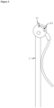
- the tab (5) has a curved shape in one position, some of which move away from the neck (3) and then approach the neck (3) again ( Figure 3 ).
- Said shape can be, for example, in the form of an R.
- the neck (3) and the tab (5) together form an "R" shape in one position.
- Said curved structure of the tab (5) provides a hollow form to receive the item to be held, thus ensuring that the position of said item is stable.
- the tab (5) may also be manufactured from an anti-slip material or at least partially coated with such a material to prevent the placed item from slipping.
- the support apparatus (1) of the present invention has at least one lower connection means (2) suitable for connecting two necks (3).
- the necks (3) are connected to said lower connection means (2) so as to rotate independently of each other.
- the necks (3) can be moved so as to approach or move away from each other.
- the necks (3) and the tabs (5) connected to said necks (3) are adjusted according to the dimensions of the item to be placed in the rack.
- the support apparatus (1) of the present invention can be used with a dishwasher rack. However, it is also possible to use said support apparatus (1) with structures such as a dish rack which is used for placing and drying hand-washed dishes.
- the dishwasher rack of the present invention has a support apparatus as described above.
- the dishwasher of the present invention has a dishwasher rack as described above.
Landscapes
- Washing And Drying Of Tableware (AREA)
Abstract
Description
- The present invention relates to a support apparatus especially for dishwasher racks, a rack having such a support apparatus, and a dishwasher having such a rack.
- Dishwashers have racks for placing the items to be washed. The items to be washed are placed in said rack and the washing cycle is started. Generally, water is sprayed on the items in the rack by means of a spraying member, and thus said items are cleaned.
- The dishwasher racks have a wire mesh structure so that the water used during washing does not accumulate in the rack. The rack also has wires for placing plates, etc. in an ideal position for washing. However, the wires of the rack do not have the length and spacing to balance the standing of pots and bowls. Therefore, such items can only be positioned with their mouths facing down. This arrangement causes said items to occupy too much space.
- Therefore, there is a need for a support apparatus which supports different items and facilitates the placement of such items in the rack.
- In the state of the art Patent Document No.
US2012306333 , a support apparatus which can attached to an existing rack is disclosed. Although said apparatus provides the dishwasher rack with the ability to support different items, said apparatus cannot be adjusted according to the item to be supported. However, there is a need for a support apparatus which can be adapted to different items to be placed in the rack. - The aim of the present invention is the realization of a support apparatus especially for dishwasher racks.
- Another aim of the present invention is the realization of a support apparatus which can be adapted to different items to be placed in the rack.
- Yet another aim of the present invention is the realization of a rack which supports different items and a dishwasher having such a rack.
- The support apparatus realized in order to attain the aim of the present invention is illustrated in the attached figures, where:
-
Sekil 1. - is the view of an embodiment of the support apparatus of the present invention.
-
Sekil 2. - is the detailed view showing the connection of the lower connection means the neck to each other in an embodiment of the present invention.
-
Sekil 3. - is the view of a position of the tab with respect to the neck in an embodiment of the present invention.
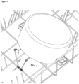
- Sekil 4.
- is the view of an exemplary use of a rack together with a pot in the present invention.
- The elements illustrated in the figures are numbered as follows:
- 1. Support apparatus
- 2. Lower connection means
- 21. Wire housing
- 22. Neck connection opening
- 23. Adjustment means
- 3. Neck
31. Connection protrusion - 4. Upper connection means
41. Tab connection opening
411. Tab adjustment means - 5. Tab
51. Tab connection protrusion - The support apparatus (1) especially for dishwasher racks comprises
- at least one lower connection means (2) which is suitable for being connected to the dishwasher rack and which has at least one wire housing (21) suitable for receiving a wire of said dishwasher rack therein and at least one neck connection opening (22) suitable for connecting a neck and comprising at least one adjustment means (23) for adjusting the orientation of said neck,
- at least one neck (3) having at least one connection protrusion (31) connected to the adjustment means (23) of the lower connection means (2),
- at least one upper connection means (4) which is connected to the neck (3) and which has at least one tab connection opening (41) suitable for connecting a tab and comprising at least one tab adjustment means (411) for adjusting the orientation of said ear; and
- at least one tab (5) having at least one tab connection protrusion (51) connected to the tab connection opening (41) of the upper connection means (4).
- The support apparatus (1) especially for dishwasher racks comprises at least one lower connection means (2) suitable for being connected to the dishwasher rack. The lower connection means (2) has at least one wire housing (21) suitable for receiving a wire of said dishwasher rack therein.. The wire housing (21) is preferably snap-fitted to said wire. However, it is also possible to fix the wire passing through the wire housing (21) by a different fixing means, for example a clamp.
- The lower connection means (2) has at least one neck connection opening (22) suitable for connecting the neck (3). The neck (3) is connected to the connection opening (22) so as to rotate around a rotational axis located in said connection opening (22). The neck (3) can move, for example, in the X-Z plane shown in
Figure 1 . - The neck connection opening (22) has at least one adjustment means (23) for adjusting the orientation of the neck (3). The adjustment means (23) means, for example, may comprise at least two wide parts where the neck (3) has a stable position and at least one narrow part which connects said wide parts and which allows the movement of the neck (3) between said wide parts as a result of a force applied thereon (
Figure 2 ). By increasing the number of said wide parts and narrow parts, the number of stable positions can be increased. Said adjustment means (23) is preferably located on a circle concentric with the axis of rotation around which the neck (3) rotates. - The neck (3) has at least one connection protrusion (31) on one side. Said connection protrusion (31) is fitted into the adjustment means (23). Thus, the neck (3) can be positioned in the stable positions allowed by the adjustment means (23) and can be moved between said stable positions when desired.
- At least one tab connection means (4) is connected to the part of the neck (3) which is far from the lower connection means (2). The tab (5) is connected to the neck (3) by means of the tab connection means (4). The neck (3) and the tab (5) can rotate relative to each other. In case the neck (3) lies on the X-Z plane, the tab (5) can move on a plane perpendicular to both said X-Z plane and the neck (3).
- The orientation of the tab (5) can be adjusted using at least one tab adjustment means (411). The tab adjustment means (411) means, for example, may comprise at least two wide parts where the tab (5) has a stable position and at least one narrow part which connects said wide parts and which allows the movement of the tab (5) between said wide parts as a result of a force applied thereon. Said tab adjustment means (411) is preferably located on a circle concentric with the axis of rotation around which the neck (3) and the tab (5) rotates with respect to each other.
- In an embodiment of the present invention, the tab (5) has a curved shape in one position, some of which move away from the neck (3) and then approach the neck (3) again (
Figure 3 ). Said shape can be, for example, in the form of an R. In other words, the neck (3) and the tab (5) together form an "R" shape in one position. Said curved structure of the tab (5) provides a hollow form to receive the item to be held, thus ensuring that the position of said item is stable. - The tab (5) may also be manufactured from an anti-slip material or at least partially coated with such a material to prevent the placed item from slipping.
- In the preferred embodiment of the present invention, the support apparatus (1) of the present invention has at least one lower connection means (2) suitable for connecting two necks (3). The necks (3) are connected to said lower connection means (2) so as to rotate independently of each other. Thus, the necks (3) can be moved so as to approach or move away from each other. The necks (3) and the tabs (5) connected to said necks (3) are adjusted according to the dimensions of the item to be placed in the rack. By means of said adjustable structure of the support apparatus (1) of the present invention, items of different sizes can be supported in the rack.
- The support apparatus (1) of the present invention can be used with a dishwasher rack. However, it is also possible to use said support apparatus (1) with structures such as a dish rack which is used for placing and drying hand-washed dishes.
- The dishwasher rack of the present invention has a support apparatus as described above.
- The dishwasher of the present invention has a dishwasher rack as described above.
Claims (12)
- A support apparatus (1) especially for dishwasher racks comprising- at least one lower connection means (2) which is suitable for being connected to the dishwasher rack and which has at least one wire housing (21) suitable for receiving a wire of said dishwasher rack therein and which is suitable for connecting a neck, characterized by- the lower connection means (2) having at least one neck connection opening (2) comprising at least one adjustment means (23) for adjusting the orientation of said neck,- at least one neck (3) having at least one connection protrusion (31) connected to the adjustment means (23) of the lower connection means (2),- at least one upper connection means (4) which is connected to the neck (3) and which has at least one tab connection opening (41) suitable for connecting a tab and comprising at least one tab adjustment means (411) for adjusting the orientation of said ear; and- at least one tab (5) having at least one tab connection protrusion (51) connected to the tab connection opening (41) of the upper connection means (4).
- A support apparatus (1) as in Claim 1, characterized by the wire housing (21) which is snap-fitted to said wire.
- A support apparatus (1) as in Claim 1, characterized by the wire housing (21) which is connected to said wire by clamps.
- A support apparatus (1) as in any one of the above claims, characterized by the adjustment means (23) means which comprises at least two wide parts where the neck (3) has a stable position and at least one narrow part which connects said wide parts and which allows the movement of the neck (3) between said wide parts as a result of a force applied thereon.
- A support apparatus (1) as in any one of the above claims, characterized by the adjustment means (23) which is located on a circle concentric with the axis of rotation around which the neck (3) rotates.
- A support apparatus (1) as in any one of the above claims, characterized by the tab adjustment means (411) means which comprises at least two wide parts where the tab (5) has a stable position and at least one narrow part which connects said wide parts and which allows the movement of the tab (5) between said wide parts as a result of a force applied thereon.
- A support apparatus (1) as in any one of the above claims, characterized by the tab adjustment means (411) which is located on a circle concentric with the axis of rotation around which the neck (3) and the tab (5) rotate with respect to each other.
- A support apparatus (1) as in any one of the above claims, characterized by the tab (5) which has a curved shape in one position, some of which move away from the neck (3) and then approach the neck (3) again.
- A support apparatus (1) as in any one of the above claims, characterized by the tab (5) which is manufactured from an anti-slip material or at least partially coated with such a material to prevent the placed item from slipping.
- A support apparatus (1) as in any one of the above claims, characterized by the lower connection means (2) which is suitable for connecting two necks (3) so as to approach and move away from each other, independently of each other, at least two necks (3) which are connected to said lower connection means (2), two upper connection means (4), each connected to each of at least two of said necks (3), and two tabs (5), each connected to each of said upper connection means (4).
- A dishwasher rack having a support apparatus (1) as in any one of the Claims 1 to 10.
- A dishwasher having a dishwasher rack as in Claim 11.
Applications Claiming Priority (1)
| Application Number | Priority Date | Filing Date | Title |
|---|---|---|---|
| TR202122202 | 2021-12-31 |
Publications (2)
| Publication Number | Publication Date |
|---|---|
| EP4205627A1 true EP4205627A1 (en) | 2023-07-05 |
| EP4205627B1 EP4205627B1 (en) | 2024-09-04 |
Family
ID=84367324
Family Applications (1)
| Application Number | Title | Priority Date | Filing Date |
|---|---|---|---|
| EP22210256.8A Active EP4205627B1 (en) | 2021-12-31 | 2022-11-29 | A support apparatus |
Country Status (2)
| Country | Link |
|---|---|
| EP (1) | EP4205627B1 (en) |
| PL (1) | PL4205627T3 (en) |
Citations (5)
| Publication number | Priority date | Publication date | Assignee | Title |
|---|---|---|---|---|
| US20030089672A1 (en) * | 2001-11-09 | 2003-05-15 | Vanlandingham Wayne M. | Rack for reduced height washing compartment |
| DE102006055346A1 (en) * | 2006-11-23 | 2008-05-29 | BSH Bosch und Siemens Hausgeräte GmbH | Dishwasher with a storage container for goods to be cleaned |
| EP1935321A1 (en) * | 2006-12-22 | 2008-06-25 | Samsung Electronics Co., Ltd. | Vessel holder and dish washing machine having the same |
| US20080272073A1 (en) * | 2007-05-04 | 2008-11-06 | Electrolux Home Products, Inc. | Rack system and support member for supporting a folding rack in a dishwasher |
| US20120306333A1 (en) | 2011-05-31 | 2012-12-06 | Bsh Home Appliances Corporation | Accessory for dishwasher |
-
2022
- 2022-11-29 PL PL22210256.8T patent/PL4205627T3/en unknown
- 2022-11-29 EP EP22210256.8A patent/EP4205627B1/en active Active
Patent Citations (5)
| Publication number | Priority date | Publication date | Assignee | Title |
|---|---|---|---|---|
| US20030089672A1 (en) * | 2001-11-09 | 2003-05-15 | Vanlandingham Wayne M. | Rack for reduced height washing compartment |
| DE102006055346A1 (en) * | 2006-11-23 | 2008-05-29 | BSH Bosch und Siemens Hausgeräte GmbH | Dishwasher with a storage container for goods to be cleaned |
| EP1935321A1 (en) * | 2006-12-22 | 2008-06-25 | Samsung Electronics Co., Ltd. | Vessel holder and dish washing machine having the same |
| US20080272073A1 (en) * | 2007-05-04 | 2008-11-06 | Electrolux Home Products, Inc. | Rack system and support member for supporting a folding rack in a dishwasher |
| US20120306333A1 (en) | 2011-05-31 | 2012-12-06 | Bsh Home Appliances Corporation | Accessory for dishwasher |
Also Published As
| Publication number | Publication date |
|---|---|
| EP4205627B1 (en) | 2024-09-04 |
| PL4205627T3 (en) | 2025-02-17 |
Similar Documents
| Publication | Publication Date | Title |
|---|---|---|
| EP1935321B1 (en) | Vessel holder and dish washing machine having the same | |
| US8757419B2 (en) | Crockery basket comprising height-adjustable racks | |
| EP1282376B1 (en) | Dishwasher basket with vertically adjustable rack | |
| US7231929B2 (en) | Dishwasher and adjustable rack | |
| US6571965B1 (en) | Dishwasher rack with pivotable fences | |
| US3289854A (en) | Article retaining device | |
| US20080302740A1 (en) | Crockery Basket For Receiving Crockery in a Variable Manner | |
| US7988107B2 (en) | Stemware holder for an automatic dishwasher | |
| US2864509A (en) | Dish drainer | |
| US9861260B2 (en) | Dishwasher appliance and a tine assembly for a dishwasher appliance | |
| US20110192808A1 (en) | Insert for a dishwasher rack | |
| US7909181B2 (en) | Article holders | |
| CA2816866A1 (en) | Stemware holder | |
| WO2008060028A1 (en) | Dishwasher having rack with shelf holder | |
| CN106073683A (en) | Cup clamp and dish washing machine | |
| WO2008137849A1 (en) | Rack system and support member for supporting a folding rack in a dishwasher | |
| CN105996956B (en) | Movable row adjusting frame, bowl basket and dish washing machine | |
| EP4205627B1 (en) | A support apparatus | |
| EP2554101A1 (en) | Crockery support which can be positioned on the bottom of a dishwasher rack to create soft surfaces | |
| CN108464806B (en) | A flip bracket assembly for dishwasher and dishwasher | |
| EP1286616B1 (en) | Dishwasher basket with foldable crockery holder racks | |
| WO2012089464A1 (en) | A dishwasher comprising a rack | |
| EP2067431B1 (en) | Dishwasher basket with bottle holder | |
| EP3791770A1 (en) | A dishwasher comprising a bottle holder | |
| CN111407211A (en) | Dish basket and dishwasher having the same |
Legal Events
| Date | Code | Title | Description |
|---|---|---|---|
| PUAI | Public reference made under article 153(3) epc to a published international application that has entered the european phase |
Free format text: ORIGINAL CODE: 0009012 |
|
| STAA | Information on the status of an ep patent application or granted ep patent |
Free format text: STATUS: REQUEST FOR EXAMINATION WAS MADE |
|
| 17P | Request for examination filed |
Effective date: 20221129 |
|
| AK | Designated contracting states |
Kind code of ref document: A1 Designated state(s): AL AT BE BG CH CY CZ DE DK EE ES FI FR GB GR HR HU IE IS IT LI LT LU LV MC ME MK MT NL NO PL PT RO RS SE SI SK SM TR |
|
| GRAP | Despatch of communication of intention to grant a patent |
Free format text: ORIGINAL CODE: EPIDOSNIGR1 |
|
| STAA | Information on the status of an ep patent application or granted ep patent |
Free format text: STATUS: GRANT OF PATENT IS INTENDED |
|
| INTG | Intention to grant announced |
Effective date: 20240529 |
|
| RAP3 | Party data changed (applicant data changed or rights of an application transferred) |
Owner name: ARCELIK ANONIM SIRKETI |
|
| GRAS | Grant fee paid |
Free format text: ORIGINAL CODE: EPIDOSNIGR3 |
|
| GRAA | (expected) grant |
Free format text: ORIGINAL CODE: 0009210 |
|
| STAA | Information on the status of an ep patent application or granted ep patent |
Free format text: STATUS: THE PATENT HAS BEEN GRANTED |
|
| AK | Designated contracting states |
Kind code of ref document: B1 Designated state(s): AL AT BE BG CH CY CZ DE DK EE ES FI FR GB GR HR HU IE IS IT LI LT LU LV MC ME MK MT NL NO PL PT RO RS SE SI SK SM TR |
|
| REG | Reference to a national code |
Ref country code: GB Ref legal event code: FG4D |
|
| REG | Reference to a national code |
Ref country code: CH Ref legal event code: EP |
|
| REG | Reference to a national code |
Ref country code: IE Ref legal event code: FG4D |
|
| REG | Reference to a national code |
Ref country code: DE Ref legal event code: R096 Ref document number: 602022005871 Country of ref document: DE |
|
| REG | Reference to a national code |
Ref country code: LT Ref legal event code: MG9D |
|
| REG | Reference to a national code |
Ref country code: NL Ref legal event code: MP Effective date: 20240904 |
|
| PG25 | Lapsed in a contracting state [announced via postgrant information from national office to epo] |
Ref country code: NO Free format text: LAPSE BECAUSE OF FAILURE TO SUBMIT A TRANSLATION OF THE DESCRIPTION OR TO PAY THE FEE WITHIN THE PRESCRIBED TIME-LIMIT Effective date: 20241204 |
|
| PG25 | Lapsed in a contracting state [announced via postgrant information from national office to epo] |
Ref country code: GR Free format text: LAPSE BECAUSE OF FAILURE TO SUBMIT A TRANSLATION OF THE DESCRIPTION OR TO PAY THE FEE WITHIN THE PRESCRIBED TIME-LIMIT Effective date: 20241205 Ref country code: FI Free format text: LAPSE BECAUSE OF FAILURE TO SUBMIT A TRANSLATION OF THE DESCRIPTION OR TO PAY THE FEE WITHIN THE PRESCRIBED TIME-LIMIT Effective date: 20240904 |
|
| PG25 | Lapsed in a contracting state [announced via postgrant information from national office to epo] |
Ref country code: BG Free format text: LAPSE BECAUSE OF FAILURE TO SUBMIT A TRANSLATION OF THE DESCRIPTION OR TO PAY THE FEE WITHIN THE PRESCRIBED TIME-LIMIT Effective date: 20240904 |
|
| PG25 | Lapsed in a contracting state [announced via postgrant information from national office to epo] |
Ref country code: LV Free format text: LAPSE BECAUSE OF FAILURE TO SUBMIT A TRANSLATION OF THE DESCRIPTION OR TO PAY THE FEE WITHIN THE PRESCRIBED TIME-LIMIT Effective date: 20240904 |
|
| PG25 | Lapsed in a contracting state [announced via postgrant information from national office to epo] |
Ref country code: HR Free format text: LAPSE BECAUSE OF FAILURE TO SUBMIT A TRANSLATION OF THE DESCRIPTION OR TO PAY THE FEE WITHIN THE PRESCRIBED TIME-LIMIT Effective date: 20240904 |
|
| PG25 | Lapsed in a contracting state [announced via postgrant information from national office to epo] |
Ref country code: ES Free format text: LAPSE BECAUSE OF FAILURE TO SUBMIT A TRANSLATION OF THE DESCRIPTION OR TO PAY THE FEE WITHIN THE PRESCRIBED TIME-LIMIT Effective date: 20240904 Ref country code: RS Free format text: LAPSE BECAUSE OF FAILURE TO SUBMIT A TRANSLATION OF THE DESCRIPTION OR TO PAY THE FEE WITHIN THE PRESCRIBED TIME-LIMIT Effective date: 20241204 |
|
| PG25 | Lapsed in a contracting state [announced via postgrant information from national office to epo] |
Ref country code: RS Free format text: LAPSE BECAUSE OF FAILURE TO SUBMIT A TRANSLATION OF THE DESCRIPTION OR TO PAY THE FEE WITHIN THE PRESCRIBED TIME-LIMIT Effective date: 20241204 Ref country code: NO Free format text: LAPSE BECAUSE OF FAILURE TO SUBMIT A TRANSLATION OF THE DESCRIPTION OR TO PAY THE FEE WITHIN THE PRESCRIBED TIME-LIMIT Effective date: 20241204 Ref country code: LV Free format text: LAPSE BECAUSE OF FAILURE TO SUBMIT A TRANSLATION OF THE DESCRIPTION OR TO PAY THE FEE WITHIN THE PRESCRIBED TIME-LIMIT Effective date: 20240904 Ref country code: HR Free format text: LAPSE BECAUSE OF FAILURE TO SUBMIT A TRANSLATION OF THE DESCRIPTION OR TO PAY THE FEE WITHIN THE PRESCRIBED TIME-LIMIT Effective date: 20240904 Ref country code: GR Free format text: LAPSE BECAUSE OF FAILURE TO SUBMIT A TRANSLATION OF THE DESCRIPTION OR TO PAY THE FEE WITHIN THE PRESCRIBED TIME-LIMIT Effective date: 20241205 Ref country code: FI Free format text: LAPSE BECAUSE OF FAILURE TO SUBMIT A TRANSLATION OF THE DESCRIPTION OR TO PAY THE FEE WITHIN THE PRESCRIBED TIME-LIMIT Effective date: 20240904 Ref country code: ES Free format text: LAPSE BECAUSE OF FAILURE TO SUBMIT A TRANSLATION OF THE DESCRIPTION OR TO PAY THE FEE WITHIN THE PRESCRIBED TIME-LIMIT Effective date: 20240904 Ref country code: BG Free format text: LAPSE BECAUSE OF FAILURE TO SUBMIT A TRANSLATION OF THE DESCRIPTION OR TO PAY THE FEE WITHIN THE PRESCRIBED TIME-LIMIT Effective date: 20240904 |
|
| REG | Reference to a national code |
Ref country code: AT Ref legal event code: MK05 Ref document number: 1719493 Country of ref document: AT Kind code of ref document: T Effective date: 20240904 |
|
| PG25 | Lapsed in a contracting state [announced via postgrant information from national office to epo] |
Ref country code: NL Free format text: LAPSE BECAUSE OF FAILURE TO SUBMIT A TRANSLATION OF THE DESCRIPTION OR TO PAY THE FEE WITHIN THE PRESCRIBED TIME-LIMIT Effective date: 20240904 |
|
| PG25 | Lapsed in a contracting state [announced via postgrant information from national office to epo] |
Ref country code: IS Free format text: LAPSE BECAUSE OF FAILURE TO SUBMIT A TRANSLATION OF THE DESCRIPTION OR TO PAY THE FEE WITHIN THE PRESCRIBED TIME-LIMIT Effective date: 20250104 Ref country code: PT Free format text: LAPSE BECAUSE OF FAILURE TO SUBMIT A TRANSLATION OF THE DESCRIPTION OR TO PAY THE FEE WITHIN THE PRESCRIBED TIME-LIMIT Effective date: 20250106 |
|
| PG25 | Lapsed in a contracting state [announced via postgrant information from national office to epo] |
Ref country code: SM Free format text: LAPSE BECAUSE OF FAILURE TO SUBMIT A TRANSLATION OF THE DESCRIPTION OR TO PAY THE FEE WITHIN THE PRESCRIBED TIME-LIMIT Effective date: 20240904 Ref country code: RO Free format text: LAPSE BECAUSE OF FAILURE TO SUBMIT A TRANSLATION OF THE DESCRIPTION OR TO PAY THE FEE WITHIN THE PRESCRIBED TIME-LIMIT Effective date: 20240904 |
|
| PG25 | Lapsed in a contracting state [announced via postgrant information from national office to epo] |
Ref country code: AT Free format text: LAPSE BECAUSE OF FAILURE TO SUBMIT A TRANSLATION OF THE DESCRIPTION OR TO PAY THE FEE WITHIN THE PRESCRIBED TIME-LIMIT Effective date: 20240904 Ref country code: EE Free format text: LAPSE BECAUSE OF FAILURE TO SUBMIT A TRANSLATION OF THE DESCRIPTION OR TO PAY THE FEE WITHIN THE PRESCRIBED TIME-LIMIT Effective date: 20240904 |
|
| PG25 | Lapsed in a contracting state [announced via postgrant information from national office to epo] |
Ref country code: CZ Free format text: LAPSE BECAUSE OF FAILURE TO SUBMIT A TRANSLATION OF THE DESCRIPTION OR TO PAY THE FEE WITHIN THE PRESCRIBED TIME-LIMIT Effective date: 20240904 |
|
| PG25 | Lapsed in a contracting state [announced via postgrant information from national office to epo] |
Ref country code: SK Free format text: LAPSE BECAUSE OF FAILURE TO SUBMIT A TRANSLATION OF THE DESCRIPTION OR TO PAY THE FEE WITHIN THE PRESCRIBED TIME-LIMIT Effective date: 20240904 Ref country code: IT Free format text: LAPSE BECAUSE OF FAILURE TO SUBMIT A TRANSLATION OF THE DESCRIPTION OR TO PAY THE FEE WITHIN THE PRESCRIBED TIME-LIMIT Effective date: 20240904 |
|
| REG | Reference to a national code |
Ref country code: DE Ref legal event code: R097 Ref document number: 602022005871 Country of ref document: DE |
|
| PG25 | Lapsed in a contracting state [announced via postgrant information from national office to epo] |
Ref country code: MC Free format text: LAPSE BECAUSE OF FAILURE TO SUBMIT A TRANSLATION OF THE DESCRIPTION OR TO PAY THE FEE WITHIN THE PRESCRIBED TIME-LIMIT Effective date: 20240904 |
|
| PG25 | Lapsed in a contracting state [announced via postgrant information from national office to epo] |
Ref country code: DK Free format text: LAPSE BECAUSE OF FAILURE TO SUBMIT A TRANSLATION OF THE DESCRIPTION OR TO PAY THE FEE WITHIN THE PRESCRIBED TIME-LIMIT Effective date: 20240904 |
|
| PLBE | No opposition filed within time limit |
Free format text: ORIGINAL CODE: 0009261 |
|
| STAA | Information on the status of an ep patent application or granted ep patent |
Free format text: STATUS: NO OPPOSITION FILED WITHIN TIME LIMIT |
|
| PG25 | Lapsed in a contracting state [announced via postgrant information from national office to epo] |
Ref country code: LU Free format text: LAPSE BECAUSE OF NON-PAYMENT OF DUE FEES Effective date: 20241129 |
|
| 26N | No opposition filed |
Effective date: 20250605 |
|
| REG | Reference to a national code |
Ref country code: BE Ref legal event code: MM Effective date: 20241130 |
|
| PG25 | Lapsed in a contracting state [announced via postgrant information from national office to epo] |
Ref country code: SE Free format text: LAPSE BECAUSE OF FAILURE TO SUBMIT A TRANSLATION OF THE DESCRIPTION OR TO PAY THE FEE WITHIN THE PRESCRIBED TIME-LIMIT Effective date: 20240904 |
|
| PG25 | Lapsed in a contracting state [announced via postgrant information from national office to epo] |
Ref country code: BE Free format text: LAPSE BECAUSE OF NON-PAYMENT OF DUE FEES Effective date: 20241130 |
|
| PG25 | Lapsed in a contracting state [announced via postgrant information from national office to epo] |
Ref country code: FR Free format text: LAPSE BECAUSE OF NON-PAYMENT OF DUE FEES Effective date: 20241130 |
|
| PG25 | Lapsed in a contracting state [announced via postgrant information from national office to epo] |
Ref country code: IE Free format text: LAPSE BECAUSE OF NON-PAYMENT OF DUE FEES Effective date: 20241129 |
|
| PGFP | Annual fee paid to national office [announced via postgrant information from national office to epo] |
Ref country code: DE Payment date: 20251119 Year of fee payment: 4 |
|
| PGFP | Annual fee paid to national office [announced via postgrant information from national office to epo] |
Ref country code: TR Payment date: 20251111 Year of fee payment: 4 |
|
| PGFP | Annual fee paid to national office [announced via postgrant information from national office to epo] |
Ref country code: PL Payment date: 20251121 Year of fee payment: 4 |
|
| PG25 | Lapsed in a contracting state [announced via postgrant information from national office to epo] |
Ref country code: HU Free format text: LAPSE BECAUSE OF FAILURE TO SUBMIT A TRANSLATION OF THE DESCRIPTION OR TO PAY THE FEE WITHIN THE PRESCRIBED TIME-LIMIT; INVALID AB INITIO Effective date: 20221129 |
|
| PG25 | Lapsed in a contracting state [announced via postgrant information from national office to epo] |
Ref country code: CY Free format text: LAPSE BECAUSE OF FAILURE TO SUBMIT A TRANSLATION OF THE DESCRIPTION OR TO PAY THE FEE WITHIN THE PRESCRIBED TIME-LIMIT; INVALID AB INITIO Effective date: 20221129 |
|
| PG25 | Lapsed in a contracting state [announced via postgrant information from national office to epo] |
Ref country code: SI Free format text: LAPSE BECAUSE OF FAILURE TO SUBMIT A TRANSLATION OF THE DESCRIPTION OR TO PAY THE FEE WITHIN THE PRESCRIBED TIME-LIMIT Effective date: 20240904 |
|
| REG | Reference to a national code |
Ref country code: CH Ref legal event code: H13 Free format text: ST27 STATUS EVENT CODE: U-0-0-H10-H13 (AS PROVIDED BY THE NATIONAL OFFICE) Effective date: 20260623 |
|
| PG25 | Lapsed in a contracting state [announced via postgrant information from national office to epo] |
Ref country code: LT Free format text: LAPSE BECAUSE OF FAILURE TO SUBMIT A TRANSLATION OF THE DESCRIPTION OR TO PAY THE FEE WITHIN THE PRESCRIBED TIME-LIMIT Effective date: 20240904 |
|
| PG25 | Lapsed in a contracting state [announced via postgrant information from national office to epo] |
Ref country code: ME Free format text: LAPSE BECAUSE OF FAILURE TO SUBMIT A TRANSLATION OF THE DESCRIPTION OR TO PAY THE FEE WITHIN THE PRESCRIBED TIME-LIMIT Effective date: 20240904 |
|
| PG25 | Lapsed in a contracting state [announced via postgrant information from national office to epo] |
Ref country code: CH Free format text: LAPSE BECAUSE OF NON-PAYMENT OF DUE FEES Effective date: 20251130 |