EP4205073B1 - Visualization of non-conformance of objects via heat maps - Google Patents
Visualization of non-conformance of objects via heat maps Download PDFInfo
- Publication number
- EP4205073B1 EP4205073B1 EP21769589.9A EP21769589A EP4205073B1 EP 4205073 B1 EP4205073 B1 EP 4205073B1 EP 21769589 A EP21769589 A EP 21769589A EP 4205073 B1 EP4205073 B1 EP 4205073B1
- Authority
- EP
- European Patent Office
- Prior art keywords
- component associated
- heat map
- procedure
- component
- database
- Prior art date
- Legal status (The legal status is an assumption and is not a legal conclusion. Google has not performed a legal analysis and makes no representation as to the accuracy of the status listed.)
- Active
Links
Images




Classifications
-
- G—PHYSICS
- G06—COMPUTING OR CALCULATING; COUNTING
- G06F—ELECTRIC DIGITAL DATA PROCESSING
- G06F16/00—Information retrieval; Database structures therefor; File system structures therefor
- G06F16/90—Details of database functions independent of the retrieved data types
- G06F16/903—Querying
- G06F16/90335—Query processing
-
- G—PHYSICS
- G06—COMPUTING OR CALCULATING; COUNTING
- G06K—GRAPHICAL DATA READING; PRESENTATION OF DATA; RECORD CARRIERS; HANDLING RECORD CARRIERS
- G06K7/00—Methods or arrangements for sensing record carriers, e.g. for reading patterns
- G06K7/10—Methods or arrangements for sensing record carriers, e.g. for reading patterns by electromagnetic radiation, e.g. optical sensing; by corpuscular radiation
- G06K7/10009—Methods or arrangements for sensing record carriers, e.g. for reading patterns by electromagnetic radiation, e.g. optical sensing; by corpuscular radiation sensing by radiation using wavelengths larger than 0.1 mm, e.g. radio-waves or microwaves
- G06K7/10366—Methods or arrangements for sensing record carriers, e.g. for reading patterns by electromagnetic radiation, e.g. optical sensing; by corpuscular radiation sensing by radiation using wavelengths larger than 0.1 mm, e.g. radio-waves or microwaves the interrogation device being adapted for miscellaneous applications
-
- G—PHYSICS
- G06—COMPUTING OR CALCULATING; COUNTING
- G06K—GRAPHICAL DATA READING; PRESENTATION OF DATA; RECORD CARRIERS; HANDLING RECORD CARRIERS
- G06K7/00—Methods or arrangements for sensing record carriers, e.g. for reading patterns
- G06K7/10—Methods or arrangements for sensing record carriers, e.g. for reading patterns by electromagnetic radiation, e.g. optical sensing; by corpuscular radiation
- G06K7/14—Methods or arrangements for sensing record carriers, e.g. for reading patterns by electromagnetic radiation, e.g. optical sensing; by corpuscular radiation using light without selection of wavelength, e.g. sensing reflected white light
- G06K7/1404—Methods for optical code recognition
- G06K7/1408—Methods for optical code recognition the method being specifically adapted for the type of code
- G06K7/1413—1D bar codes
-
- G—PHYSICS
- G06—COMPUTING OR CALCULATING; COUNTING
- G06K—GRAPHICAL DATA READING; PRESENTATION OF DATA; RECORD CARRIERS; HANDLING RECORD CARRIERS
- G06K7/00—Methods or arrangements for sensing record carriers, e.g. for reading patterns
- G06K7/10—Methods or arrangements for sensing record carriers, e.g. for reading patterns by electromagnetic radiation, e.g. optical sensing; by corpuscular radiation
- G06K7/14—Methods or arrangements for sensing record carriers, e.g. for reading patterns by electromagnetic radiation, e.g. optical sensing; by corpuscular radiation using light without selection of wavelength, e.g. sensing reflected white light
- G06K7/1404—Methods for optical code recognition
- G06K7/1408—Methods for optical code recognition the method being specifically adapted for the type of code
- G06K7/1417—2D bar codes
-
- G—PHYSICS
- G06—COMPUTING OR CALCULATING; COUNTING
- G06T—IMAGE DATA PROCESSING OR GENERATION, IN GENERAL
- G06T11/00—Two-dimensional [2D] image generation
- G06T11/10—Texturing; Colouring; Generation of textures or colours
-
- G—PHYSICS
- G06—COMPUTING OR CALCULATING; COUNTING
- G06T—IMAGE DATA PROCESSING OR GENERATION, IN GENERAL
- G06T11/00—Two-dimensional [2D] image generation
- G06T11/20—Drawing from basic elements
- G06T11/26—Drawing of charts or graphs
-
- G—PHYSICS
- G06—COMPUTING OR CALCULATING; COUNTING
- G06T—IMAGE DATA PROCESSING OR GENERATION, IN GENERAL
- G06T7/00—Image analysis
- G06T7/0002—Inspection of images, e.g. flaw detection
- G06T7/0004—Industrial image inspection
-
- G—PHYSICS
- G06—COMPUTING OR CALCULATING; COUNTING
- G06V—IMAGE OR VIDEO RECOGNITION OR UNDERSTANDING
- G06V20/00—Scenes; Scene-specific elements
- G06V20/20—Scenes; Scene-specific elements in augmented reality scenes
-
- G—PHYSICS
- G09—EDUCATION; CRYPTOGRAPHY; DISPLAY; ADVERTISING; SEALS
- G09B—EDUCATIONAL OR DEMONSTRATION APPLIANCES; APPLIANCES FOR TEACHING, OR COMMUNICATING WITH, THE BLIND, DEAF OR MUTE; MODELS; PLANETARIA; GLOBES; MAPS; DIAGRAMS
- G09B19/00—Teaching not covered by other main groups of this subclass
- G09B19/003—Repetitive work cycles; Sequence of movements
-
- G—PHYSICS
- G09—EDUCATION; CRYPTOGRAPHY; DISPLAY; ADVERTISING; SEALS
- G09B—EDUCATIONAL OR DEMONSTRATION APPLIANCES; APPLIANCES FOR TEACHING, OR COMMUNICATING WITH, THE BLIND, DEAF OR MUTE; MODELS; PLANETARIA; GLOBES; MAPS; DIAGRAMS
- G09B5/00—Electrically-operated educational appliances
- G09B5/02—Electrically-operated educational appliances with visual presentation of the material to be studied, e.g. using film strip
-
- G—PHYSICS
- G06—COMPUTING OR CALCULATING; COUNTING
- G06T—IMAGE DATA PROCESSING OR GENERATION, IN GENERAL
- G06T2200/00—Indexing scheme for image data processing or generation, in general
- G06T2200/24—Indexing scheme for image data processing or generation, in general involving graphical user interfaces [GUIs]
-
- G—PHYSICS
- G06—COMPUTING OR CALCULATING; COUNTING
- G06T—IMAGE DATA PROCESSING OR GENERATION, IN GENERAL
- G06T2207/00—Indexing scheme for image analysis or image enhancement
- G06T2207/30—Subject of image; Context of image processing
- G06T2207/30108—Industrial image inspection
- G06T2207/30141—Printed circuit board [PCB]
-
- G—PHYSICS
- G06—COMPUTING OR CALCULATING; COUNTING
- G06V—IMAGE OR VIDEO RECOGNITION OR UNDERSTANDING
- G06V30/00—Character recognition; Recognising digital ink; Document-oriented image-based pattern recognition
- G06V30/10—Character recognition
Definitions
- the present disclosure relates to the visualization of non-conformance of objects via heat maps, and in an embodiment, but not by way of limitation, the visualization of non-conformance of objects via heat maps using augmented reality.
- CCAs circuit card assemblies
- a trained operator can examine the product and determine if there are any non-conformances in the finished product.
- the trained operator can use one or more pieces of equipment to aid in this examination, such as an x-ray machine.
- some non-conformances can be missed because the amount of CCAs produced by a production line in a day can be quite large, and the operator can become fatigued.
- current examination procedures do not have any aggregation of data relating to failures that can be used by the operator.
- US 2020/160083 A1 discloses a computer implemented method for surface defect inspection that includes recording an optical image of a surface including a defect; converting the optical image including the defect into a heat map; extracting a region of interest including the defect from the heat map; and comparing the region of interest including the defect from the heat map to a binary classification model using a sliding window based voting mechanism to determine if the defect is greater than or less than a threshold failure value.
- US 2020/118345 A1 discloses a method, apparatus, and system for visualizing nonconformance data for a physical object.
- An augmented reality application in a portable computing device plots, in a defined coordinate cube, points corresponding to nonconformance locations on the physical object.
- the augmented reality application determines a sub-set of the points plotted that correspond to a region of the physical object visible in an image of the region of the physical object acquired by the portable computing device at a position of the portable computing device, where the sub-set of the points exclude nonconformance locations occluded from view by a physical object structure of the physical object in the image.
- the augmented reality application displays the nonconformance data for the sub-set of the points visible in the image in association with a sub-set of the nonconformance locations for the physical object in the image displayed on a display system in the portable computing device.
- the present disclosure provides a process comprising: receiving into an augmented reality, AR, device an image of an object, wherein the object comprises a manufactured good, and wherein the manufactured good comprises a printed circuit board; receiving information for identifying the object or a component associated with the object; accessing a database to retrieve data relating to the object or the component associated with the object, wherein the data retrieved from the database relating to the object or the component associated with the object comprises a failure history of the object or the component associated with the object; creating a heat map as a function of the data relating to the object or the component associated with the object, wherein the heat map comprises visual non-conformances on the printed circuit board; displaying the heat map on a computer display device; and locating one or more fiducials associated with the object or the component associated with the object, wherein the one or more fiducials comprise an other object that is placed in a field of view of the AR device such that the other object comprises a point of reference or measure in the field of view of the AR device.
- the present disclosure provides a non-transitory computer readable medium comprising instructions that when executed by a computer processor executes a process comprising: receiving into an augmented reality, AR, device an image of an object, wherein the object comprises a manufactured good, and wherein the manufactured good comprises a printed circuit board; receiving information for identifying the object or a component associated with the object; accessing a database to retrieve data relating to the object or the component associated with the object, wherein the data retrieved from the database relating to the object or the component associated with the object comprises a failure history of the object or the component associated with the object; creating a heat map as a function of the data relating to the object or the component associated with the object, wherein the heat map comprises visual non-conformances on the printed circuit board; displaying the heat map on a computer display device; and locating one or more fiducials associated with the object or the component associated with the object, wherein the one or more fiducials comprise an other object that is placed in a field of view of the AR
- the present disclosure provides a system comprising: an augmented reality device; and a computer database coupled to the augmented reality device; wherein the system is operable for: receiving into the augmented reality device an image of an object, wherein the object comprises a manufactured good, and wherein the manufactured good comprises a printed circuit board; receiving information for identifying the object or a component associated with the object; accessing the computer database to retrieve data relating to the object or the component associated with the object, wherein the data retrieved from the database relating to the object or the component associated with the object comprises a failure history of the object or the component associated with the object; creating a heat map as a function of the data relating to the object or the component associated with the object, wherein the heat map comprises visual non-conformances on the printed circuit board; displaying the heat map on a computer display device; and locating one or more fiducials associated with the object or the component associated with the object, wherein the one or more fiducials comprise an other object that is placed in a field of view of the
- An embodiment of the present disclosure relates to leveraging object character recognition (OCR) capabilities in supporting manufacturing operations.
- the embodiment can be implemented on a mobile device.
- the embodiment can be linked with risk and opportunity management processes (risk-probability matrix, waterfall charts, etc. ) .
- risk-probability matrix, waterfall charts, etc. A full digital make-up of the manufacturing operations can be created, and past, present, and future data on manufacturing (assembly, inspection, test procedures) can be displayed to a person involved in the manufacturing operation on any device.
- the embodiment can leverage visualization techniques to provide heat maps, and risk and opportunity waterfall charts, to assist in manufacturing or maintenance procedures. These heat maps can illustrate high probability areas for failure in the manufacturing process. Additionally, an embodiment can provide overlays or display high level data for manufacturing and maintenance environments.
- data aggregation techniques can be visually represented on computer card assemblies (CCA) and other hardware and manufactured products (such as automobiles, planes, cabinets, and additive manufactured products) to assist in augmentation in an augmented reality (AR) environment for work instructions, test assessments/troubleshooting, and inspection operations.
- CCA computer card assemblies
- AR augmented reality
- Manufacturing real time data and historical data can be leveraged to provide heat maps of risks and opportunities within the non-conformances. For example, an inspection task can highlight high risk areas that have failed within the most recently manufactured units. A test engineer can then access data relating to the most recently failed components or parts to help provide real updates on past data. Visualization of these data can be shown on a mobile device or other devices.
- FIG. 1A is a block diagram of an embodiment of a system for determining non-conformance of an object.
- An AR system 100 works in conjunction with a manufacturing system 110.
- the system includes a database 120, which includes data such as a history of the manufacturing processes and the products manufactured by the manufacturing processes. As noted above, these data are used in the AR system to identify historical non-conformances in the manufacturing process.
- the AR system 100 can further include an Internet of Things (IOT) platform 130.
- IOT Internet of Things
- the manufactured good itself can have Internet-access capabilities, and these capabilities can be used to retrieve data over the Internet and share data over the Internet.
- information is provided about the manufactured good such as maintenance procedures, installation procedures, replacement procedures, assembly procedures, inspection procedures, and test procedures. As indicated at 150, this information can be provided to manufacturing personnel via an AR headset 152 , a mobile device 154, and/or some type of computer display device 156 . At 160, information relating to the actual maintenance procedures, installation procedures, replacement procedures, assembly procedures, inspection procedures, and test procedures that were performed on the manufactured good are captured at 170 and provided as feedback in the AR system 100 .
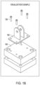
- FIG. 1B illustrates an example of a visualization.
- the system displays components 182 and 184 , and several fasteners 180 to couple the components 182 and 184.
- the visualization can further include instructions such as a fastening pattern and the amount of torque to be applied to the fasteners.
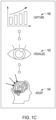
- the system 100 permits manufacturing personnel to consider captured data at 190, to visualize the maintenance procedures, installation procedures, replacement procedures, assembly procedures, inspection procedures, and test procedures at 192, and to make any needed adjustments via the maintenance procedures, installation procedures, replacement procedures, assembly procedures, inspection procedures, and test procedures at 194.
- FIG. 2 is an example of a risk waterfall chart 200.
- the AR system 100 is used to identify and react to non-conformances, the severity levels of the non-conformances fail from highly severe 210, to moderately severe 220, to a low severity 230.
- the severities can be color-coded, such as red for highly severe 210, yellow for moderately severe 220, and green for the low severity 230 .
- FIG. 3 is an example of an opportunity waterfall chart 300. As time proceeds and the AR system 100 is used to identify and react to non-conformances, new opportunities are taken.
- the severity level rises from a low severity level at 310, to a moderate severity level at 320, to a high severity level at 330 .
- the severities can be color-coded in the opportunity waterfall chart 300, such as red for highly severe 330, yellow for moderately severe 320, and green for the low severity 310.
- FIG. 4 is an example of a probability-consequence chart 400 .
- the probability-consequence chart is used to determine the risk factor for the risk waterfall chart 200. For example, if there is a low probability of occurrence of an event, e.g., a 2 at 410, and a low consequence if that event occurs, e.g ., a 2 at 420, then the risk factor is a relatively low 4 ( i.e., the product of the two). However, if there is a high probability of occurrence of an event, e.g ., a 4 at 430, and a high consequence if that event occurs, e.g ., a 5 at 440, then the risk factor is a relatively high 20.
- FIG. 5 illustrates examples of ranges that can be used to determine these risk factors.
- FIG. 6 is an example of a benefit-feasibility chart.
- the benefits-feasibility chart 600 is used to determine the opportunity factor for the opportunity waterfall chart 300. For example, if there is a low benefit associated with the occurrence of an event, e.g ., a 1 at 610, and a low consequence if that event occurs, e.g ., a 2 at 620, then the opportunity factor is a relatively low 2. However, if there is a high benefit associated with the occurrence of an event, e.g ., a 4 at 630, and a high consequence if that event occurs, e.g ., a 5 at 640, then the opportunity factor is a relatively high 20.
- FIG. 7 illustrates examples of ranges that can be used to determine these opportunity factors.
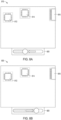
- FIGS. 8A and 8B are examples of heat maps 810 and 830 that are associated with a printed circuit board.
- the heat maps 810 and 830 are a way to visualize trends in manufacturing data historically. For example, if manufacturing personnel are actively inspecting a particular type of board over a time period, they may be able to see as the color shifts from red to yellow indicating the manufacturing quality is moving in the right direction for that particular board or product line. But if the manufacturing person starts up a new run from the day before or takes over from a prior shift, that person, without the benefits of the heat map, won't have any reference for how that part has performed up to that point in time.
- the person has the ability of sselling the index/count that they are inspecting, and they can scroll through data based on different snapshots of the board window, and they can understand how the heat map of the board has progressed. This provides opportunities for manufacturing leadership to use heat maps to understand the trend rates of their hardware, to understand and use learning curves, and to better train their employees.
- component 812 is outlined in two boxes, indicating a color of yellow, which indicates a severity history of moderate, and FIG. 8B illustrates that component 812 still has a moderate severity because it is still enclosed in a yellow box (as indicated by the two boxes).
- component 814 is outlined in three boxes, indicating a color of red, which indicates a severity history of high, and FIG. 8B illustrates that component 814 has progressed in the proper direction as it is now outlined in a yellow box (two boxes) indicating moderate severity.
- FIG. 8A component 812 is outlined in two boxes, indicating a color of yellow, which indicates a severity history of moderate
- FIG. 8B illustrates that component 814 has progressed in the proper direction as it is now outlined in a yellow box (two boxes) indicating moderate severity.
- component 816 is outlined in two boxes, indicating a color of yellow, which indicates a severity history of moderate, and FIG. 8B illustrates that component 816 is now outlined in a single box, indicating a color of green, which indicates that component 816 has improved to a low severity.
- FIGS. 8A and 8B further illustrate an input device 820, such as a slider, which permits a user such as manufacturing personnel to select a particular object or a particular component of the object on a computer display device. This selection can be used to access a database and retrieve the information about the particular object or the particular component.
- the input device 820 can further be used to select, for example, the part number of the manufactured good and a specific quantity or date range of when the good was manufactured.
- FIG. 9 is a flowchart of an example embodiment of a process for generating a heat map for an object.
- FIG. 9 includes a number of process blocks 910 - 965. Though arranged substantially serially in the example of FIG. 9 , other examples may reorder the blocks, omit one or more blocks, and/or execute two or more blocks in parallel using multiple processors or a single processor organized as two or more virtual machines or sub-processors. Moreover, still other examples can implement the blocks as one or more specific interconnected hardware or integrated circuit modules with related control and data signals communicated between and through the modules. Thus, any process flow is applicable to software, firmware, hardware, and hybrid implementations.
- an image of an object is received into an augmented reality device.
- the augmented reality device can be an off the shelf head set, a computer tablet, or some other mobile device.
- the object can be a manufactured good, and more particularly, the object can be a printed circuit board ( 915 ).
- the heat map can include visual non-conformances on the printed circuit board.
- information is received for identifying the object or a component associated with the object.
- one or more fiducials that are associated with the object or the component of the object are located using OCR.
- a fiducial is another object that is placed in the field of view of the AR device, and this other object appears in the view of the AR device. This other object can be used as a point of reference or measure.
- the information is received via one or more of object character recognition (OCR), text, barcode, quick response (QR) code, human input, or radio frequency identification (RFID).
- the AR device can sense radio frequency identification (RFID) information associated with the object or the component associated with the object.
- a database is accessed to retrieve data relating to the object or the component that is associated with the object.
- the data retrieved from the database relating to the object or the component associated with the object is a failure history of the object or the component associated with the object.
- the data retrieved from the database can also relate to such things as a maintenance procedure for the object or the component associated with the object, an installation procedure for the object or the component associated with the object, a replacement procedure for the object or the component associated with the object, an assembly procedure for the object or the component associated with the object, an inspection procedure for the object or the component associated with the object, and a test procedure for the object or the component associated with the object ( 934 ).
- a heat map is created as a function of the data relating to the object or the component associated with the object, and at 950, the heat map is displayed on a computer display device.
- a computer display device can be an AR headset, a tablet, a laptop computer, or some other computer device.
- the display can be an overlay of the heat map onto the object (952).
- the overlay of the heat map on a printed circuit board can identify components that have recently been experiencing problems, and the overlay can further indicate in which direction the problems associated with the component are trending.
- the display on the computer display device can include a risk chart, an opportunity waterfall chart, and a probability matrix relating to the object or the component associated with the object (954).
- a selection of a particular object or a particular component of the object is received from manufacturing personnel. This selection is used to access the database and retrieve the information about the particular object or the particular component.
- this feature can be implemented using a slider device on a computer display unit. The slider is used to select, for example, the part number of the manufactured good and a specific quantity or date range of when the good was manufactured.
- a selection of one or more colors is received from manufacturing personnel for use on the heat map. This feature is particularly useful for persons who are color-blind to certain colors.
- This feature like the feature of operation 960, can be implemented via a slider device on a computer display unit. In another embodiment, color is not used as an indicator on the computer display unit, but different shapes such as circles, triangles, and squares.
Landscapes
- Engineering & Computer Science (AREA)
- Physics & Mathematics (AREA)
- Theoretical Computer Science (AREA)
- General Physics & Mathematics (AREA)
- Computer Vision & Pattern Recognition (AREA)
- Health & Medical Sciences (AREA)
- Toxicology (AREA)
- Business, Economics & Management (AREA)
- Electromagnetism (AREA)
- General Health & Medical Sciences (AREA)
- Artificial Intelligence (AREA)
- Educational Technology (AREA)
- Educational Administration (AREA)
- Databases & Information Systems (AREA)
- Quality & Reliability (AREA)
- Multimedia (AREA)
- Entrepreneurship & Innovation (AREA)
- Data Mining & Analysis (AREA)
- General Engineering & Computer Science (AREA)
- Computational Linguistics (AREA)
- Processing Or Creating Images (AREA)
- Management, Administration, Business Operations System, And Electronic Commerce (AREA)
Description
- The present disclosure relates to the visualization of non-conformance of objects via heat maps, and in an embodiment, but not by way of limitation, the visualization of non-conformance of objects via heat maps using augmented reality.
- There is a desire within any manufacturing environment to reduce the risk associated with manufacturing processes, especially processes that involve human steps or interactions. Such a reduction in the risk should result in a reduction in defects and non-conformances in the products produced by the manufacturing processes.
- For example, in the manufacture of circuit card assemblies (CCAs), it is desirable to reduce the percentage of defects in the finished product. This is presently accomplished in several ways. A trained operator can examine the product and determine if there are any non-conformances in the finished product. The trained operator can use one or more pieces of equipment to aid in this examination, such as an x-ray machine. However, some non-conformances can be missed because the amount of CCAs produced by a production line in a day can be quite large, and the operator can become fatigued. Additionally, current examination procedures do not have any aggregation of data relating to failures that can be used by the operator.
-
US 2020/160083 A1 discloses a computer implemented method for surface defect inspection that includes recording an optical image of a surface including a defect; converting the optical image including the defect into a heat map; extracting a region of interest including the defect from the heat map; and comparing the region of interest including the defect from the heat map to a binary classification model using a sliding window based voting mechanism to determine if the defect is greater than or less than a threshold failure value. -
US 2020/118345 A1 discloses a method, apparatus, and system for visualizing nonconformance data for a physical object. An augmented reality application in a portable computing device plots, in a defined coordinate cube, points corresponding to nonconformance locations on the physical object. The augmented reality application determines a sub-set of the points plotted that correspond to a region of the physical object visible in an image of the region of the physical object acquired by the portable computing device at a position of the portable computing device, where the sub-set of the points exclude nonconformance locations occluded from view by a physical object structure of the physical object in the image. The augmented reality application displays the nonconformance data for the sub-set of the points visible in the image in association with a sub-set of the nonconformance locations for the physical object in the image displayed on a display system in the portable computing device. - In an aspect, the present disclosure provides a process comprising: receiving into an augmented reality, AR, device an image of an object, wherein the object comprises a manufactured good, and wherein the manufactured good comprises a printed circuit board; receiving information for identifying the object or a component associated with the object; accessing a database to retrieve data relating to the object or the component associated with the object, wherein the data retrieved from the database relating to the object or the component associated with the object comprises a failure history of the object or the component associated with the object; creating a heat map as a function of the data relating to the object or the component associated with the object, wherein the heat map comprises visual non-conformances on the printed circuit board; displaying the heat map on a computer display device; and locating one or more fiducials associated with the object or the component associated with the object, wherein the one or more fiducials comprise an other object that is placed in a field of view of the AR device such that the other object comprises a point of reference or measure in the field of view of the AR device.
- In another aspect, the present disclosure provides a non-transitory computer readable medium comprising instructions that when executed by a computer processor executes a process comprising: receiving into an augmented reality, AR, device an image of an object, wherein the object comprises a manufactured good, and wherein the manufactured good comprises a printed circuit board; receiving information for identifying the object or a component associated with the object; accessing a database to retrieve data relating to the object or the component associated with the object, wherein the data retrieved from the database relating to the object or the component associated with the object comprises a failure history of the object or the component associated with the object; creating a heat map as a function of the data relating to the object or the component associated with the object, wherein the heat map comprises visual non-conformances on the printed circuit board; displaying the heat map on a computer display device; and locating one or more fiducials associated with the object or the component associated with the object, wherein the one or more fiducials comprise an other object that is placed in a field of view of the AR device such that the other object comprises a point of reference or measure in the field of view of the AR device.
- In another aspect, the present disclosure provides a system comprising: an augmented reality device; and a computer database coupled to the augmented reality device; wherein the system is operable for: receiving into the augmented reality device an image of an object, wherein the object comprises a manufactured good, and wherein the manufactured good comprises a printed circuit board; receiving information for identifying the object or a component associated with the object; accessing the computer database to retrieve data relating to the object or the component associated with the object, wherein the data retrieved from the database relating to the object or the component associated with the object comprises a failure history of the object or the component associated with the object; creating a heat map as a function of the data relating to the object or the component associated with the object, wherein the heat map comprises visual non-conformances on the printed circuit board; displaying the heat map on a computer display device; and locating one or more fiducials associated with the object or the component associated with the object, wherein the one or more fiducials comprise an other object that is placed in a field of view of the AR device such that the other object comprises a point of reference or measure in the field of view of the AR device.
-
-
FIGS. 1A ,1B , and1C are block diagrams of an embodiment of a system for determining non-conformance of an object. -
FIG. 2 is an example of a risk waterfall chart. -
FIG. 3 is an example of an opportunity waterfall chart. -
FIG. 4 is an example of a probability-consequence chart. -
FIG. 5 is an example of ranges that can be used to determine the risk factors in the probability-consequence chart ofFIG. 4 . -
FIG. 6 is an example of a benefit-feasibility chart. -
FIG. 7 is an example of ranges that can be used to determine the opportunity factors in the benefit-feasibility chart ofFIG. 6 . -
FIGS. 8A and 8B are examples of heat maps that are associated with a printed circuit board. -
FIG. 9 is a flowchart of an example embodiment of a process for generating a heat map for an object. - In the following description, for purposes of explanation, numerous specific details are set forth in order to provide a thorough understanding of the various aspects of different embodiments of the present invention. It will be evident, however, to one skilled in the art, that the present invention may be practiced without all the specific details and/or with variations, permutations, and combinations of the various features and elements described herein.
- An embodiment of the present disclosure relates to leveraging object character recognition (OCR) capabilities in supporting manufacturing operations. The embodiment can be implemented on a mobile device. The embodiment can be linked with risk and opportunity management processes (risk-probability matrix, waterfall charts, etc.). A full digital make-up of the manufacturing operations can be created, and past, present, and future data on manufacturing (assembly, inspection, test procedures) can be displayed to a person involved in the manufacturing operation on any device. The embodiment can leverage visualization techniques to provide heat maps, and risk and opportunity waterfall charts, to assist in manufacturing or maintenance procedures. These heat maps can illustrate high probability areas for failure in the manufacturing process. Additionally, an embodiment can provide overlays or display high level data for manufacturing and maintenance environments.
- In real time, data aggregation techniques (waterfall and probability maps) can be visually represented on computer card assemblies (CCA) and other hardware and manufactured products (such as automobiles, planes, cabinets, and additive manufactured products) to assist in augmentation in an augmented reality (AR) environment for work instructions, test assessments/troubleshooting, and inspection operations. Manufacturing real time data and historical data can be leveraged to provide heat maps of risks and opportunities within the non-conformances. For example, an inspection task can highlight high risk areas that have failed within the most recently manufactured units. A test engineer can then access data relating to the most recently failed components or parts to help provide real updates on past data. Visualization of these data can be shown on a mobile device or other devices.
-
FIG. 1A is a block diagram of an embodiment of a system for determining non-conformance of an object. AnAR system 100 works in conjunction with amanufacturing system 110. The system includes adatabase 120, which includes data such as a history of the manufacturing processes and the products manufactured by the manufacturing processes. As noted above, these data are used in the AR system to identify historical non-conformances in the manufacturing process. TheAR system 100 can further include an Internet of Things (IOT)platform 130. For example, the manufactured good itself can have Internet-access capabilities, and these capabilities can be used to retrieve data over the Internet and share data over the Internet. At 140, using thedatabase 120 and/or theIOT platform 130, information is provided about the manufactured good such as maintenance procedures, installation procedures, replacement procedures, assembly procedures, inspection procedures, and test procedures. As indicated at 150, this information can be provided to manufacturing personnel via anAR headset 152, amobile device 154, and/or some type ofcomputer display device 156. At 160, information relating to the actual maintenance procedures, installation procedures, replacement procedures, assembly procedures, inspection procedures, and test procedures that were performed on the manufactured good are captured at 170 and provided as feedback in theAR system 100. -
FIG. 1B illustrates an example of a visualization. InFIG. 1B , the system displayscomponents several fasteners 180 to couple thecomponents FIG. 1C , thesystem 100 permits manufacturing personnel to consider captured data at 190, to visualize the maintenance procedures, installation procedures, replacement procedures, assembly procedures, inspection procedures, and test procedures at 192, and to make any needed adjustments via the maintenance procedures, installation procedures, replacement procedures, assembly procedures, inspection procedures, and test procedures at 194. -
FIG. 2 is an example of arisk waterfall chart 200. As time proceeds and theAR system 100 is used to identify and react to non-conformances, the severity levels of the non-conformances fail from highly severe 210, to moderately severe 220, to alow severity 230. The severities can be color-coded, such as red for highly severe 210, yellow for moderately severe 220, and green for thelow severity 230.FIG. 3 is an example of anopportunity waterfall chart 300. As time proceeds and theAR system 100 is used to identify and react to non-conformances, new opportunities are taken. However, with these new opportunities, over time, the severity level rises from a low severity level at 310, to a moderate severity level at 320, to a high severity level at 330. Like with therisk waterfall chart 200, the severities can be color-coded in theopportunity waterfall chart 300, such as red for highly severe 330, yellow for moderately severe 320, and green for thelow severity 310. -
FIG. 4 is an example of a probability-consequence chart 400. The probability-consequence chart is used to determine the risk factor for therisk waterfall chart 200. For example, if there is a low probability of occurrence of an event, e.g., a 2 at 410, and a low consequence if that event occurs, e.g., a 2 at 420, then the risk factor is a relatively low 4 (i.e., the product of the two). However, if there is a high probability of occurrence of an event, e.g., a 4 at 430, and a high consequence if that event occurs, e.g., a 5 at 440, then the risk factor is a relatively high 20.FIG. 5 illustrates examples of ranges that can be used to determine these risk factors. -
FIG. 6 is an example of a benefit-feasibility chart. The benefits-feasibility chart 600 is used to determine the opportunity factor for theopportunity waterfall chart 300. For example, if there is a low benefit associated with the occurrence of an event, e.g., a 1 at 610, and a low consequence if that event occurs, e.g., a 2 at 620, then the opportunity factor is a relatively low 2. However, if there is a high benefit associated with the occurrence of an event, e.g., a 4 at 630, and a high consequence if that event occurs, e.g., a 5 at 640, then the opportunity factor is a relatively high 20.FIG. 7 illustrates examples of ranges that can be used to determine these opportunity factors. -
FIGS. 8A and 8B are examples ofheat maps heat maps - Referring specifically to
FIGS. 8A and 8B , inFIG. 8A ,component 812 is outlined in two boxes, indicating a color of yellow, which indicates a severity history of moderate, andFIG. 8B illustrates thatcomponent 812 still has a moderate severity because it is still enclosed in a yellow box (as indicated by the two boxes). InFIG. 8A ,component 814 is outlined in three boxes, indicating a color of red, which indicates a severity history of high, andFIG. 8B illustrates thatcomponent 814 has progressed in the proper direction as it is now outlined in a yellow box (two boxes) indicating moderate severity. InFIG. 8A ,component 816 is outlined in two boxes, indicating a color of yellow, which indicates a severity history of moderate, andFIG. 8B illustrates thatcomponent 816 is now outlined in a single box, indicating a color of green, which indicates thatcomponent 816 has improved to a low severity. These progressions indicating a worsening severity and a lessening severity will catch the attention of manufacturing personnel.FIGS. 8A and 8B further illustrate aninput device 820, such as a slider, which permits a user such as manufacturing personnel to select a particular object or a particular component of the object on a computer display device. This selection can be used to access a database and retrieve the information about the particular object or the particular component. Theinput device 820 can further be used to select, for example, the part number of the manufactured good and a specific quantity or date range of when the good was manufactured. -
FIG. 9 is a flowchart of an example embodiment of a process for generating a heat map for an object.FIG. 9 includes a number of process blocks 910 - 965. Though arranged substantially serially in the example ofFIG. 9 , other examples may reorder the blocks, omit one or more blocks, and/or execute two or more blocks in parallel using multiple processors or a single processor organized as two or more virtual machines or sub-processors. Moreover, still other examples can implement the blocks as one or more specific interconnected hardware or integrated circuit modules with related control and data signals communicated between and through the modules. Thus, any process flow is applicable to software, firmware, hardware, and hybrid implementations. - Referring specifically now to
FIG. 9, at 910, an image of an object is received into an augmented reality device. As indicated at 912, the augmented reality device can be an off the shelf head set, a computer tablet, or some other mobile device. As further indicated at 914, the object can be a manufactured good, and more particularly, the object can be a printed circuit board (915). When the object is a printed circuit board, the heat map can include visual non-conformances on the printed circuit board. - At 920, information is received for identifying the object or a component associated with the object. At 922, one or more fiducials that are associated with the object or the component of the object are located using OCR. In this context, a fiducial is another object that is placed in the field of view of the AR device, and this other object appears in the view of the AR device. This other object can be used as a point of reference or measure. As indicated at 924, the information is received via one or more of object character recognition (OCR), text, barcode, quick response (QR) code, human input, or radio frequency identification (RFID). And as further indicated at 925, the AR device can sense radio frequency identification (RFID) information associated with the object or the component associated with the object.
- At 930, a database is accessed to retrieve data relating to the object or the component that is associated with the object. As indicated at 932, the data retrieved from the database relating to the object or the component associated with the object is a failure history of the object or the component associated with the object. The data retrieved from the database can also relate to such things as a maintenance procedure for the object or the component associated with the object, an installation procedure for the object or the component associated with the object, a replacement procedure for the object or the component associated with the object, an assembly procedure for the object or the component associated with the object, an inspection procedure for the object or the component associated with the object, and a test procedure for the object or the component associated with the object (934).
- At 940, a heat map is created as a function of the data relating to the object or the component associated with the object, and at 950, the heat map is displayed on a computer display device. As noted above, such a computer display device can be an AR headset, a tablet, a laptop computer, or some other computer device. The display can be an overlay of the heat map onto the object (952). For example, as discussed above, the overlay of the heat map on a printed circuit board can identify components that have recently been experiencing problems, and the overlay can further indicate in which direction the problems associated with the component are trending. In addition to a heat map overlay, the display on the computer display device can include a risk chart, an opportunity waterfall chart, and a probability matrix relating to the object or the component associated with the object (954).
- At 960, a selection of a particular object or a particular component of the object is received from manufacturing personnel. This selection is used to access the database and retrieve the information about the particular object or the particular component. In an embodiment, this feature can be implemented using a slider device on a computer display unit. The slider is used to select, for example, the part number of the manufactured good and a specific quantity or date range of when the good was manufactured.
- At 965, a selection of one or more colors is received from manufacturing personnel for use on the heat map. This feature is particularly useful for persons who are color-blind to certain colors. This feature, like the feature of
operation 960, can be implemented via a slider device on a computer display unit. In another embodiment, color is not used as an indicator on the computer display unit, but different shapes such as circles, triangles, and squares. - The scope of various embodiments is defined only by the appended claims.
Claims (14)
- A process comprising:receiving (910) into an augmented reality, AR, device (152, 154, 156) an image of an object, wherein the object comprises a manufactured good, and wherein the manufactured good comprises a printed circuit board;receiving (920) information for identifying the object or a component associated with the object;accessing (930) a database (120) to retrieve data relating to the object or the component associated with the object, wherein the data retrieved from the database relating to the object or the component associated with the object comprises a failure history of the object or the component associated with the object;creating (940) a heat map as a function of the data relating to the object or the component associated with the object, wherein the heat map comprises visual non-conformances on the printed circuit board;displaying (950) the heat map on a computer display device; andlocating (922) one or more fiducials associated with the object or the component associated with the object, wherein the one or more fiducials comprise an other object that is placed in a field of view of the AR device such that the other object comprises a point of reference or measure in the field of view of the AR device.
- The process of claim 1, wherein the AR device comprises a commercial off the shelf headset (152), computer tablet (156), or mobile device (154).
- The process of claim 1, wherein the information is received (924) via one or more of object character recognition, OCR, text, barcode, quick response, QR, code, human input, or radio frequency identification,RFID.
- The process of claim 1, comprising displaying one or more of a maintenance procedure for the object or the component associated with the object, an installation procedure for the object or the component associated with the object, a replacement procedure for the object or the component associated with the object, an assembly procedure for the object or the component associated with the object, an inspection procedure for the object or the component associated with the object, and a test procedure for the object or the component associated with the object.
- The process of claim 1, comprising displaying (954) on the computer display device one or more of a risk chart (200), an opportunity waterfall chart (300), and a probability matrix (400) relating to the object or the component associated with the object.
- The process of claim 1, comprising overlaying the heat map onto the object using the AR device.
- The process of claim 1, comprising receiving (960) a selection of a particular object or a particular component of the object.
- The process of claim 1, comprising receiving (965) a selection of one or more colors for use on the heat map.
- A non-transitory computer readable medium comprising instructions that when executed by a computer processor executes a process comprising:receiving (910) into an augmented reality, AR, device (152, 154, 156) an image of an object, wherein the object comprises a manufactured good, and wherein the manufactured good comprises a printed circuit board;receiving (920) information for identifying the object or a component associated with the object;accessing (930) a database (120) to retrieve data relating to the object or the component associated with the object, wherein the data retrieved from the database relating to the object or the component associated with the object comprises a failure history of the object or the component associated with the object;creating (940) a heat map as a function of the data relating to the object or the component associated with the object, wherein the heat map comprises visual non-conformances on the printed circuit board;displaying (950) the heat map on a computer display device; andlocating (922) one or more fiducials associated with the object or the component associated with the object, wherein the one or more fiducials comprise an other object that is placed in a field of view of the AR device such that the other object comprises a point of reference or measure in the field of view of the AR device.
- The non-transitory computer readable medium of claim 9, wherein the information is received via one or more of object character recognition, OCR, text, barcode, quick response, QR, code, human input, or radio frequency identification, RFID.
- The non-transitory computer readable medium of claim 9, comprising displaying one or more of a maintenance procedure for the object or the component associated with the object, an installation procedure for the object or the component associated with the object, a replacement procedure for the object or the component associated with the object, an assembly procedure for the object or the component associated with the object, an inspection procedure for the object or the component associated with the object, and a test procedure for the object or the component associated with the object.
- The non-transitory computer readable medium of claim 9, comprising displaying on the computer display device one or more of a risk chart (200), an opportunity waterfall chart (300), and a probability matrix (400) relating to the object or the component associated with the object.
- The non-transitory computer readable medium of claim 9, comprising overlaying the heat map onto the object using the AR device.
- A system (100) comprising:an augmented reality device (152, 154, 156); anda computer database (120) coupled to the augmented reality device;wherein the system is operable for:receiving (910) into the augmented reality device an image of an object, wherein the object comprises a manufactured good, and wherein the manufactured good comprises a printed circuit board;receiving (920) information for identifying the object or a component associated with the object;accessing (930) the computer database to retrieve data relating to the object or the component associated with the object, wherein the data retrieved from the database relating to the object or the component associated with the object comprises a failure history of the object or the component associated with the object;creating (940) a heat map as a function of the data relating to the object or the component associated with the object, wherein the heat map comprises visual non-conformances on the printed circuit board;displaying (950) the heat map on a computer display device; andlocating (922) one or more fiducials associated with the object or the component associated with the object, wherein the one or more fiducials comprise an other object that is placed in a field of view of the AR device such that the other object comprises a point of reference or measure in the field of view of the AR device.
Applications Claiming Priority (2)
| Application Number | Priority Date | Filing Date | Title |
|---|---|---|---|
| US17/002,306 US11527063B2 (en) | 2020-08-25 | 2020-08-25 | Visualization of non-conformance of objects via heat maps |
| PCT/US2021/046692 WO2022046512A1 (en) | 2020-08-25 | 2021-08-19 | Visualization of non-conformance of objects via heat maps |
Publications (2)
| Publication Number | Publication Date |
|---|---|
| EP4205073A1 EP4205073A1 (en) | 2023-07-05 |
| EP4205073B1 true EP4205073B1 (en) | 2025-02-19 |
Family
ID=77726566
Family Applications (1)
| Application Number | Title | Priority Date | Filing Date |
|---|---|---|---|
| EP21769589.9A Active EP4205073B1 (en) | 2020-08-25 | 2021-08-19 | Visualization of non-conformance of objects via heat maps |
Country Status (4)
| Country | Link |
|---|---|
| US (1) | US11527063B2 (en) |
| EP (1) | EP4205073B1 (en) |
| KR (1) | KR20230053641A (en) |
| WO (1) | WO2022046512A1 (en) |
Families Citing this family (3)
| Publication number | Priority date | Publication date | Assignee | Title |
|---|---|---|---|---|
| US11611608B1 (en) | 2019-07-19 | 2023-03-21 | Snap Inc. | On-demand camera sharing over a network |
| US12154230B2 (en) | 2020-09-09 | 2024-11-26 | Snap Inc. | Augmented reality messenger system |
| WO2022061362A1 (en) * | 2020-09-16 | 2022-03-24 | Snap Inc. | Augmented reality auto reactions |
Family Cites Families (8)
| Publication number | Priority date | Publication date | Assignee | Title |
|---|---|---|---|---|
| US8732524B2 (en) * | 2011-08-03 | 2014-05-20 | Honeywell International Inc. | Systems and methods for using a corrective action as diagnostic evidence |
| US9897434B2 (en) | 2014-10-21 | 2018-02-20 | Hand Held Products, Inc. | Handheld dimensioning system with measurement-conformance feedback |
| US9589390B2 (en) | 2015-05-13 | 2017-03-07 | The Boeing Company | Wire harness assembly |
| US10360728B2 (en) | 2015-05-19 | 2019-07-23 | Hand Held Products, Inc. | Augmented reality device, system, and method for safety |
| US10078916B2 (en) | 2016-07-01 | 2018-09-18 | Invia Robotics, Inc. | Pick to augmented reality |
| US10866631B2 (en) * | 2016-11-09 | 2020-12-15 | Rockwell Automation Technologies, Inc. | Methods, systems, apparatuses, and techniques for employing augmented reality and virtual reality |
| US10740987B2 (en) | 2018-10-12 | 2020-08-11 | The Boeing Company | Augmented reality system for visualizing nonconformance data for an object |
| US10896341B2 (en) * | 2018-11-15 | 2021-01-19 | International Business Machines Corporation | Efficient defect localization/segmentation for surface defect inspection |
-
2020
- 2020-08-25 US US17/002,306 patent/US11527063B2/en active Active
-
2021
- 2021-08-19 WO PCT/US2021/046692 patent/WO2022046512A1/en not_active Ceased
- 2021-08-19 KR KR1020237008996A patent/KR20230053641A/en active Pending
- 2021-08-19 EP EP21769589.9A patent/EP4205073B1/en active Active
Also Published As
| Publication number | Publication date |
|---|---|
| US20220067373A1 (en) | 2022-03-03 |
| WO2022046512A1 (en) | 2022-03-03 |
| EP4205073A1 (en) | 2023-07-05 |
| KR20230053641A (en) | 2023-04-21 |
| US11527063B2 (en) | 2022-12-13 |
Similar Documents
| Publication | Publication Date | Title |
|---|---|---|
| US12190418B2 (en) | Methods for automatically generating a common measurement across multiple assembly units | |
| US11527063B2 (en) | Visualization of non-conformance of objects via heat maps | |
| CN116664551B (en) | Display screen detection method, device, equipment and storage medium based on machine vision | |
| US11164351B2 (en) | Augmented reality for sensor applications | |
| US9824436B2 (en) | System for inspecting objects using augmented reality | |
| EP2913148B1 (en) | Method and system for analyzing process monitoring data | |
| US8041443B2 (en) | Surface defect data display and management system and a method of displaying and managing a surface defect data | |
| JP7493390B2 (en) | Monitoring system | |
| EP4165417A1 (en) | System and method for manufacturing and maintenance | |
| Pavlov et al. | Case study of using virtual and augmented reality in industrial system monitoring | |
| US10783403B2 (en) | Automated design testing through deep learning | |
| JPWO2022123628A5 (en) | Equipment inspection support system, equipment inspection support method, and equipment inspection support program | |
| CN120071195A (en) | Airtight space unmanned aerial vehicle intelligent inspection method and device based on AI visual recognition | |
| CN113989464A (en) | Electricity safety inspection equipment and analysis method | |
| CN118607267A (en) | A digital twin construction method and system for panel production line | |
| JP5634142B2 (en) | Parts retrieval device and parts retrieval computer program | |
| US7797130B1 (en) | Baseline comparative leading indicator analysis | |
| US8094154B1 (en) | Intelligent leading indicator display | |
| JP2023088155A (en) | Monitoring system | |
| CN116701724B (en) | A method, apparatus and electronic device for determining airborne anomaly data | |
| WO2018207605A1 (en) | Anomaly assessment device, anomaly assessment method, and anomaly assessment program | |
| CN120599372A (en) | Method, device, electronic device and storage medium for detecting defects in power equipment components | |
| CN108900808A (en) | The method and device that robot is monitored equipment | |
| CN119719639A (en) | A production process abnormality identification method and abnormality identification device | |
| CN120495699A (en) | Method and device for checking satellite assembly process, electronic equipment and storage medium |
Legal Events
| Date | Code | Title | Description |
|---|---|---|---|
| STAA | Information on the status of an ep patent application or granted ep patent |
Free format text: STATUS: UNKNOWN |
|
| STAA | Information on the status of an ep patent application or granted ep patent |
Free format text: STATUS: THE INTERNATIONAL PUBLICATION HAS BEEN MADE |
|
| PUAI | Public reference made under article 153(3) epc to a published international application that has entered the european phase |
Free format text: ORIGINAL CODE: 0009012 |
|
| STAA | Information on the status of an ep patent application or granted ep patent |
Free format text: STATUS: REQUEST FOR EXAMINATION WAS MADE |
|
| 17P | Request for examination filed |
Effective date: 20230317 |
|
| AK | Designated contracting states |
Kind code of ref document: A1 Designated state(s): AL AT BE BG CH CY CZ DE DK EE ES FI FR GB GR HR HU IE IS IT LI LT LU LV MC MK MT NL NO PL PT RO RS SE SI SK SM TR |
|
| DAV | Request for validation of the european patent (deleted) | ||
| DAX | Request for extension of the european patent (deleted) | ||
| GRAP | Despatch of communication of intention to grant a patent |
Free format text: ORIGINAL CODE: EPIDOSNIGR1 |
|
| STAA | Information on the status of an ep patent application or granted ep patent |
Free format text: STATUS: GRANT OF PATENT IS INTENDED |
|
| INTG | Intention to grant announced |
Effective date: 20241031 |
|
| GRAS | Grant fee paid |
Free format text: ORIGINAL CODE: EPIDOSNIGR3 |
|
| GRAA | (expected) grant |
Free format text: ORIGINAL CODE: 0009210 |
|
| STAA | Information on the status of an ep patent application or granted ep patent |
Free format text: STATUS: THE PATENT HAS BEEN GRANTED |
|
| AK | Designated contracting states |
Kind code of ref document: B1 Designated state(s): AL AT BE BG CH CY CZ DE DK EE ES FI FR GB GR HR HU IE IS IT LI LT LU LV MC MK MT NL NO PL PT RO RS SE SI SK SM TR |
|
| REG | Reference to a national code |
Ref country code: GB Ref legal event code: FG4D |
|
| REG | Reference to a national code |
Ref country code: CH Ref legal event code: EP |
|
| REG | Reference to a national code |
Ref country code: IE Ref legal event code: FG4D |
|
| REG | Reference to a national code |
Ref country code: DE Ref legal event code: R096 Ref document number: 602021026429 Country of ref document: DE |
|
| REG | Reference to a national code |
Ref country code: NL Ref legal event code: MP Effective date: 20250219 |
|
| PG25 | Lapsed in a contracting state [announced via postgrant information from national office to epo] |
Ref country code: RS Free format text: LAPSE BECAUSE OF FAILURE TO SUBMIT A TRANSLATION OF THE DESCRIPTION OR TO PAY THE FEE WITHIN THE PRESCRIBED TIME-LIMIT Effective date: 20250519 |
|
| PG25 | Lapsed in a contracting state [announced via postgrant information from national office to epo] |
Ref country code: FI Free format text: LAPSE BECAUSE OF FAILURE TO SUBMIT A TRANSLATION OF THE DESCRIPTION OR TO PAY THE FEE WITHIN THE PRESCRIBED TIME-LIMIT Effective date: 20250219 |
|
| PG25 | Lapsed in a contracting state [announced via postgrant information from national office to epo] |
Ref country code: PL Free format text: LAPSE BECAUSE OF FAILURE TO SUBMIT A TRANSLATION OF THE DESCRIPTION OR TO PAY THE FEE WITHIN THE PRESCRIBED TIME-LIMIT Effective date: 20250219 |
|
| PG25 | Lapsed in a contracting state [announced via postgrant information from national office to epo] |
Ref country code: ES Free format text: LAPSE BECAUSE OF FAILURE TO SUBMIT A TRANSLATION OF THE DESCRIPTION OR TO PAY THE FEE WITHIN THE PRESCRIBED TIME-LIMIT Effective date: 20250219 |
|
| REG | Reference to a national code |
Ref country code: LT Ref legal event code: MG9D |
|
| PG25 | Lapsed in a contracting state [announced via postgrant information from national office to epo] |
Ref country code: NO Free format text: LAPSE BECAUSE OF FAILURE TO SUBMIT A TRANSLATION OF THE DESCRIPTION OR TO PAY THE FEE WITHIN THE PRESCRIBED TIME-LIMIT Effective date: 20250519 Ref country code: IS Free format text: LAPSE BECAUSE OF FAILURE TO SUBMIT A TRANSLATION OF THE DESCRIPTION OR TO PAY THE FEE WITHIN THE PRESCRIBED TIME-LIMIT Effective date: 20250619 |
|
| PG25 | Lapsed in a contracting state [announced via postgrant information from national office to epo] |
Ref country code: NL Free format text: LAPSE BECAUSE OF FAILURE TO SUBMIT A TRANSLATION OF THE DESCRIPTION OR TO PAY THE FEE WITHIN THE PRESCRIBED TIME-LIMIT Effective date: 20250219 |
|
| PG25 | Lapsed in a contracting state [announced via postgrant information from national office to epo] |
Ref country code: HR Free format text: LAPSE BECAUSE OF FAILURE TO SUBMIT A TRANSLATION OF THE DESCRIPTION OR TO PAY THE FEE WITHIN THE PRESCRIBED TIME-LIMIT Effective date: 20250219 |
|
| PG25 | Lapsed in a contracting state [announced via postgrant information from national office to epo] |
Ref country code: PT Free format text: LAPSE BECAUSE OF FAILURE TO SUBMIT A TRANSLATION OF THE DESCRIPTION OR TO PAY THE FEE WITHIN THE PRESCRIBED TIME-LIMIT Effective date: 20250620 Ref country code: LV Free format text: LAPSE BECAUSE OF FAILURE TO SUBMIT A TRANSLATION OF THE DESCRIPTION OR TO PAY THE FEE WITHIN THE PRESCRIBED TIME-LIMIT Effective date: 20250219 |
|
| PG25 | Lapsed in a contracting state [announced via postgrant information from national office to epo] |
Ref country code: GR Free format text: LAPSE BECAUSE OF FAILURE TO SUBMIT A TRANSLATION OF THE DESCRIPTION OR TO PAY THE FEE WITHIN THE PRESCRIBED TIME-LIMIT Effective date: 20250520 Ref country code: BG Free format text: LAPSE BECAUSE OF FAILURE TO SUBMIT A TRANSLATION OF THE DESCRIPTION OR TO PAY THE FEE WITHIN THE PRESCRIBED TIME-LIMIT Effective date: 20250219 |
|
| REG | Reference to a national code |
Ref country code: AT Ref legal event code: MK05 Ref document number: 1769045 Country of ref document: AT Kind code of ref document: T Effective date: 20250219 |
|
| PG25 | Lapsed in a contracting state [announced via postgrant information from national office to epo] |
Ref country code: SE Free format text: LAPSE BECAUSE OF FAILURE TO SUBMIT A TRANSLATION OF THE DESCRIPTION OR TO PAY THE FEE WITHIN THE PRESCRIBED TIME-LIMIT Effective date: 20250219 |
|
| PG25 | Lapsed in a contracting state [announced via postgrant information from national office to epo] |
Ref country code: SM Free format text: LAPSE BECAUSE OF FAILURE TO SUBMIT A TRANSLATION OF THE DESCRIPTION OR TO PAY THE FEE WITHIN THE PRESCRIBED TIME-LIMIT Effective date: 20250219 |
|
| PG25 | Lapsed in a contracting state [announced via postgrant information from national office to epo] |
Ref country code: DK Free format text: LAPSE BECAUSE OF FAILURE TO SUBMIT A TRANSLATION OF THE DESCRIPTION OR TO PAY THE FEE WITHIN THE PRESCRIBED TIME-LIMIT Effective date: 20250219 |
|
| PGFP | Annual fee paid to national office [announced via postgrant information from national office to epo] |
Ref country code: DE Payment date: 20250724 Year of fee payment: 5 |
|
| PG25 | Lapsed in a contracting state [announced via postgrant information from national office to epo] |
Ref country code: IT Free format text: LAPSE BECAUSE OF FAILURE TO SUBMIT A TRANSLATION OF THE DESCRIPTION OR TO PAY THE FEE WITHIN THE PRESCRIBED TIME-LIMIT Effective date: 20250219 |
|
| PGFP | Annual fee paid to national office [announced via postgrant information from national office to epo] |
Ref country code: GB Payment date: 20250724 Year of fee payment: 5 |
|
| PG25 | Lapsed in a contracting state [announced via postgrant information from national office to epo] |
Ref country code: AT Free format text: LAPSE BECAUSE OF FAILURE TO SUBMIT A TRANSLATION OF THE DESCRIPTION OR TO PAY THE FEE WITHIN THE PRESCRIBED TIME-LIMIT Effective date: 20250219 |
|
| PGFP | Annual fee paid to national office [announced via postgrant information from national office to epo] |
Ref country code: FR Payment date: 20250725 Year of fee payment: 5 |
|
| PG25 | Lapsed in a contracting state [announced via postgrant information from national office to epo] |
Ref country code: EE Free format text: LAPSE BECAUSE OF FAILURE TO SUBMIT A TRANSLATION OF THE DESCRIPTION OR TO PAY THE FEE WITHIN THE PRESCRIBED TIME-LIMIT Effective date: 20250219 Ref country code: CZ Free format text: LAPSE BECAUSE OF FAILURE TO SUBMIT A TRANSLATION OF THE DESCRIPTION OR TO PAY THE FEE WITHIN THE PRESCRIBED TIME-LIMIT Effective date: 20250219 |
|
| PG25 | Lapsed in a contracting state [announced via postgrant information from national office to epo] |
Ref country code: RO Free format text: LAPSE BECAUSE OF FAILURE TO SUBMIT A TRANSLATION OF THE DESCRIPTION OR TO PAY THE FEE WITHIN THE PRESCRIBED TIME-LIMIT Effective date: 20250219 |
|
| PG25 | Lapsed in a contracting state [announced via postgrant information from national office to epo] |
Ref country code: SK Free format text: LAPSE BECAUSE OF FAILURE TO SUBMIT A TRANSLATION OF THE DESCRIPTION OR TO PAY THE FEE WITHIN THE PRESCRIBED TIME-LIMIT Effective date: 20250219 |
|
| REG | Reference to a national code |
Ref country code: DE Ref legal event code: R097 Ref document number: 602021026429 Country of ref document: DE |
|
| PLBE | No opposition filed within time limit |
Free format text: ORIGINAL CODE: 0009261 |
|
| STAA | Information on the status of an ep patent application or granted ep patent |
Free format text: STATUS: NO OPPOSITION FILED WITHIN TIME LIMIT |
|
| REG | Reference to a national code |
Ref country code: CH Ref legal event code: L10 Free format text: ST27 STATUS EVENT CODE: U-0-0-L10-L00 (AS PROVIDED BY THE NATIONAL OFFICE) Effective date: 20251231 |
|
| 26N | No opposition filed |
Effective date: 20251120 |
|
| REG | Reference to a national code |
Ref country code: CH Ref legal event code: H13 Free format text: ST27 STATUS EVENT CODE: U-0-0-H10-H13 (AS PROVIDED BY THE NATIONAL OFFICE) Effective date: 20260324 |
|
| PG25 | Lapsed in a contracting state [announced via postgrant information from national office to epo] |
Ref country code: MC Free format text: LAPSE BECAUSE OF FAILURE TO SUBMIT A TRANSLATION OF THE DESCRIPTION OR TO PAY THE FEE WITHIN THE PRESCRIBED TIME-LIMIT Effective date: 20250219 |
|
| PG25 | Lapsed in a contracting state [announced via postgrant information from national office to epo] |
Ref country code: LU Free format text: LAPSE BECAUSE OF NON-PAYMENT OF DUE FEES Effective date: 20250819 |
|
| PG25 | Lapsed in a contracting state [announced via postgrant information from national office to epo] |
Ref country code: CH Free format text: LAPSE BECAUSE OF NON-PAYMENT OF DUE FEES Effective date: 20250831 |