EP4204750B1 - Electrostatic spray dryer apparatus and method - Google Patents
Electrostatic spray dryer apparatus and method Download PDFInfo
- Publication number
- EP4204750B1 EP4204750B1 EP21791493.6A EP21791493A EP4204750B1 EP 4204750 B1 EP4204750 B1 EP 4204750B1 EP 21791493 A EP21791493 A EP 21791493A EP 4204750 B1 EP4204750 B1 EP 4204750B1
- Authority
- EP
- European Patent Office
- Prior art keywords
- powder
- plenum
- heat exchanger
- gas
- cooling water
- Prior art date
- Legal status (The legal status is an assumption and is not a legal conclusion. Google has not performed a legal analysis and makes no representation as to the accuracy of the status listed.)
- Active
Links
Images


Classifications
-
- F—MECHANICAL ENGINEERING; LIGHTING; HEATING; WEAPONS; BLASTING
- F26—DRYING
- F26B—DRYING SOLID MATERIALS OR OBJECTS BY REMOVING LIQUID THEREFROM
- F26B3/00—Drying solid materials or objects by processes involving the application of heat
- F26B3/02—Drying solid materials or objects by processes involving the application of heat by convection, i.e. heat being conveyed from a heat source to the materials or objects to be dried by a gas or vapour, e.g. air
- F26B3/10—Drying solid materials or objects by processes involving the application of heat by convection, i.e. heat being conveyed from a heat source to the materials or objects to be dried by a gas or vapour, e.g. air the gas or vapour carrying the materials or objects to be dried with it
- F26B3/12—Drying solid materials or objects by processes involving the application of heat by convection, i.e. heat being conveyed from a heat source to the materials or objects to be dried by a gas or vapour, e.g. air the gas or vapour carrying the materials or objects to be dried with it in the form of a spray, i.e. sprayed or dispersed emulsions or suspensions
-
- B—PERFORMING OPERATIONS; TRANSPORTING
- B01—PHYSICAL OR CHEMICAL PROCESSES OR APPARATUS IN GENERAL
- B01D—SEPARATION
- B01D1/00—Evaporating
- B01D1/16—Evaporating by spraying
-
- B—PERFORMING OPERATIONS; TRANSPORTING
- B01—PHYSICAL OR CHEMICAL PROCESSES OR APPARATUS IN GENERAL
- B01J—CHEMICAL OR PHYSICAL PROCESSES, e.g. CATALYSIS OR COLLOID CHEMISTRY; THEIR RELEVANT APPARATUS
- B01J2/00—Processes or devices for granulating materials, e.g. fertilisers in general; Rendering particulate materials free flowing in general, e.g. making them hydrophobic
- B01J2/02—Processes or devices for granulating materials, e.g. fertilisers in general; Rendering particulate materials free flowing in general, e.g. making them hydrophobic by dividing the liquid material into drops, e.g. by spraying, and solidifying the drops
-
- B—PERFORMING OPERATIONS; TRANSPORTING
- B01—PHYSICAL OR CHEMICAL PROCESSES OR APPARATUS IN GENERAL
- B01J—CHEMICAL OR PHYSICAL PROCESSES, e.g. CATALYSIS OR COLLOID CHEMISTRY; THEIR RELEVANT APPARATUS
- B01J2/00—Processes or devices for granulating materials, e.g. fertilisers in general; Rendering particulate materials free flowing in general, e.g. making them hydrophobic
- B01J2/02—Processes or devices for granulating materials, e.g. fertilisers in general; Rendering particulate materials free flowing in general, e.g. making them hydrophobic by dividing the liquid material into drops, e.g. by spraying, and solidifying the drops
- B01J2/04—Processes or devices for granulating materials, e.g. fertilisers in general; Rendering particulate materials free flowing in general, e.g. making them hydrophobic by dividing the liquid material into drops, e.g. by spraying, and solidifying the drops in a gaseous medium
-
- B—PERFORMING OPERATIONS; TRANSPORTING
- B05—SPRAYING OR ATOMISING IN GENERAL; APPLYING FLUENT MATERIALS TO SURFACES, IN GENERAL
- B05B—SPRAYING APPARATUS; ATOMISING APPARATUS; NOZZLES
- B05B5/00—Electrostatic spraying apparatus; Spraying apparatus with means for charging the spray electrically; Apparatus for spraying liquids or other fluent materials by other electric means
- B05B5/08—Plant for applying liquids or other fluent materials to objects
- B05B5/081—Plant for applying liquids or other fluent materials to objects specially adapted for treating particulate materials
-
- F—MECHANICAL ENGINEERING; LIGHTING; HEATING; WEAPONS; BLASTING
- F26—DRYING
- F26B—DRYING SOLID MATERIALS OR OBJECTS BY REMOVING LIQUID THEREFROM
- F26B21/00—Arrangements for supplying or controlling air or other gases for drying solid materials or objects
- F26B21/20—Circulating air or gases in closed cycles, e.g. wholly within the drying enclosure
- F26B21/25—Circulating air or gases in closed cycles, e.g. wholly within the drying enclosure partly outside the drying enclosure
-
- F—MECHANICAL ENGINEERING; LIGHTING; HEATING; WEAPONS; BLASTING
- F26—DRYING
- F26B—DRYING SOLID MATERIALS OR OBJECTS BY REMOVING LIQUID THEREFROM
- F26B21/00—Arrangements for supplying or controlling air or other gases for drying solid materials or objects
- F26B21/30—Controlling, e.g. regulating, parameters of gas supply
- F26B21/33—Humidity
- F26B21/333—Humidity by condensing the moisture in the drying medium, which may be recycled, e.g. using a heat pump cycle
-
- F—MECHANICAL ENGINEERING; LIGHTING; HEATING; WEAPONS; BLASTING
- F26—DRYING
- F26B—DRYING SOLID MATERIALS OR OBJECTS BY REMOVING LIQUID THEREFROM
- F26B25/00—Details of general application not covered by group F26B21/00 or F26B23/00
- F26B25/001—Handling, e.g. loading or unloading arrangements
- F26B25/002—Handling, e.g. loading or unloading arrangements for bulk goods
-
- F—MECHANICAL ENGINEERING; LIGHTING; HEATING; WEAPONS; BLASTING
- F26—DRYING
- F26B—DRYING SOLID MATERIALS OR OBJECTS BY REMOVING LIQUID THEREFROM
- F26B25/00—Details of general application not covered by group F26B21/00 or F26B23/00
- F26B25/06—Chambers, containers, or receptacles
- F26B25/14—Chambers, containers, receptacles of simple construction
- F26B25/16—Chambers, containers, receptacles of simple construction mainly closed, e.g. drum
-
- F—MECHANICAL ENGINEERING; LIGHTING; HEATING; WEAPONS; BLASTING
- F26—DRYING
- F26B—DRYING SOLID MATERIALS OR OBJECTS BY REMOVING LIQUID THEREFROM
- F26B3/00—Drying solid materials or objects by processes involving the application of heat
- F26B3/02—Drying solid materials or objects by processes involving the application of heat by convection, i.e. heat being conveyed from a heat source to the materials or objects to be dried by a gas or vapour, e.g. air
- F26B3/14—Drying solid materials or objects by processes involving the application of heat by convection, i.e. heat being conveyed from a heat source to the materials or objects to be dried by a gas or vapour, e.g. air the materials or objects to be dried being moved by gravity
-
- B—PERFORMING OPERATIONS; TRANSPORTING
- B05—SPRAYING OR ATOMISING IN GENERAL; APPLYING FLUENT MATERIALS TO SURFACES, IN GENERAL
- B05B—SPRAYING APPARATUS; ATOMISING APPARATUS; NOZZLES
- B05B5/00—Electrostatic spraying apparatus; Spraying apparatus with means for charging the spray electrically; Apparatus for spraying liquids or other fluent materials by other electric means
- B05B5/08—Plant for applying liquids or other fluent materials to objects
- B05B5/087—Arrangements of electrodes, e.g. of charging, shielding, collecting electrodes
Definitions
- the present invention relates generally to electrostatic spray dryers, and more particularly to an apparatus and method for spray drying liquids into dry powder form.
- Spray drying is a well-known and extensively used process in which liquid slurries are sprayed into a drying chamber into which heated air is introduced for drying the liquid into powder.
- the slurry commonly includes a liquid, such as water, an ingredient, such as a food, flavor, or pharmaceutical, and a carrier. During the drying process, the liquid is driven off leaving the ingredient in powder form encapsulated within the carrier.
- Spray drying also is used in producing powders that do not require encapsulation, such as various food products, additives, and chemicals.
- CN 204 134 241 U describes an instantaneous spray drying tower comprising a tower body, wherein an atomizer is connected to the top of the tower body, a heat exchanger is connected to the upper part of the tower body, and a material receiving room is connected to a tapered accommodating part of the tower body.
- a condensing device is arranged on the outer surface of the tapered accommodating part of the tower body, and the condensing device is composed of a condensing pipe and a cooling medium circulator connected with the condensing pipe.
- the invention is an electrostatic spray drying system according to claim 1.
- Yet another object is to provide such an electrostatic spray drying apparatus that is relatively simple in design and lends itself to economical manufacture.
- a conduit 21 in the form of a tube communicates a drying gas and powder mixture from the powder direction plenum 18 to a powder separation plenum 24 supported in upright position by the frame adjacent the processing tower 11 for filtering powder from the drying gas and directing the dried powder into a powder collection container or drum 25 and directing the filtered drying gas to return line 26.
- the nozzle supporting head 31 in this case further is formed with a radial pressurized atomizing air inlet passage 39 downstream of said liquid inlet passage 35 that communicates with a suitable pressurized air supply.
- a radial passage 41 upstream of the liquid inlet passage 35 receives a high voltage cable 44 in abutting electrically contacting relation to an electrode 48 axially supported within the head 31 and extending downstream of the liquid inlet passage 35.
- the connecting conduit 21 between the powder direction plenum 18 and the powder separation plenum 24 also comprises a water jacket constructed heat exchanger 70 having inner and outer walls 70a, 70b that define an annular cooling water flow passage 71, with the inner wall 70a being sized such that the gas will efficiently convey all entrained powder from the powder direction plenum 18 to the powder separation plenum 24.
- the heat exchanger 70 in this case has an angled upstream end 74 coupled to an underside of the powder direction plenum 18 and an upper angled end 75 connected to and communicating with an inlet 76 in an upper end of the powder separation plenum 24 for directing pre-cooled powder and drying gas into the plenum in a downward and tangential direction.
- the connecting conduit heat exchanger 70 has a chilled water inlet 78 coupled to a chilled water supply line 79 communicating from an outlet 81 adjacent a lower end of the powder collection plenum 18 for receiving chilled water directly from powder direction plenum heat exchanger 65.
- heating gas and powder discharging from the drying chamber 12 will come into substantial contact with the heat exchanging surfaces of the conical powder direction plenum heat exchanger 65 and the connecting conduit heat exchanger 70 for cooling before it is directed into the separation plenum 24.
- the heating gas and powder mixture discharging from the drying chamber at temperatures of 60°C-90°C can be cooled to temperatures of between about 25°C and 50°C (i.e. close to ambient temperature) prior to direction into the powder separation plenum 24.
- Such intermediate and substantial cooling has been found to prevent damage to even highly temperature sensitive powders.
Landscapes
- Engineering & Computer Science (AREA)
- Mechanical Engineering (AREA)
- General Engineering & Computer Science (AREA)
- Chemical & Material Sciences (AREA)
- Chemical Kinetics & Catalysis (AREA)
- Organic Chemistry (AREA)
- Life Sciences & Earth Sciences (AREA)
- Microbiology (AREA)
- Vaporization, Distillation, Condensation, Sublimation, And Cold Traps (AREA)
- Electrostatic Spraying Apparatus (AREA)
- Glanulating (AREA)
- Drying Of Solid Materials (AREA)
Description
- The present invention relates generally to electrostatic spray dryers, and more particularly to an apparatus and method for spray drying liquids into dry powder form.
- Spray drying is a well-known and extensively used process in which liquid slurries are sprayed into a drying chamber into which heated air is introduced for drying the liquid into powder. The slurry commonly includes a liquid, such as water, an ingredient, such as a food, flavor, or pharmaceutical, and a carrier. During the drying process, the liquid is driven off leaving the ingredient in powder form encapsulated within the carrier. Spray drying also is used in producing powders that do not require encapsulation, such as various food products, additives, and chemicals.
- Electrostatic spray drying allows for processing at temperatures below what is commonly achievable with conventional spray drying techniques, which makes the technology well-suited for processing of heat-sensitive pharmaceutical, biological, and nutraceutical compounds into dried powders. However, the potency or viability of extremely heat-sensitive compounds can be degraded after exposure at temperatures exceeding 35°C-75°C for more than a few seconds. Despite the lower operating temperature capability provided by the electrostatic drying process, powders can be exposed to damaging temperatures exceeding these limits for several minutes before the dried powder is finally collected and cooled outside of the process. This can particularly occur in the downstream filter apparatus which separates the dried powder from the drying gas, where dried particles can build up or remain in the filter system for prolonged times.
-
CN 204 134 241 U describes an instantaneous spray drying tower comprising a tower body, wherein an atomizer is connected to the top of the tower body, a heat exchanger is connected to the upper part of the tower body, and a material receiving room is connected to a tapered accommodating part of the tower body. A condensing device is arranged on the outer surface of the tapered accommodating part of the tower body, and the condensing device is composed of a condensing pipe and a cooling medium circulator connected with the condensing pipe. - The invention is an electrostatic spray drying system according to claim 1.
- It is an object of the present invention to provide an electrostatic spray drying apparatus and method for more effectively and efficiently spray drying heat sensitive powders.
- Another object is to provide an electrostatic spray drying apparatus and method as characterized above that can be operated at substantially higher production rates than conventional spray drying systems.
- A further object is to provide such an apparatus and method of the above kind that can be operated at higher temperatures for quicker and more efficient spray drying, even when producing heat sensitive powders.
- Still another object is to provide an electrostatic spray drying apparatus and method of the foregoing type in which the dried powder is separated from the drying gas in a separation plenum without exposure to high temperature drying gases.
- Yet another object is to provide such an electrostatic spray drying apparatus that is relatively simple in design and lends itself to economical manufacture.
- Other objects and advantages of the invention will become apparent upon reading the following detailed description and upon reference to the drawings.
-
-
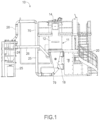
Figure 1 is a front elevational view of an illustrative spray drying system in accordance with the invention; -
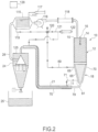
Fig. 2 is a diagrammatic depiction of the spray drying system shown inFig. 1 ; -
Fig. 3 is an enlarged vertical section of the water jacketed cone shaped powder direction plenum of the illustrated spray drying system; -
Fig. 4 is an enlarged front elevational view of the water jacketed connecting pipe for coupling between the powder direction plenum and the powder separation plenum of the illustrated embodiment; -
Fig. 5 is an enlarged vertical section of the electrostatic spray nozzle assembly of the illustrated spray drying system; and -
Fig. 6 is an enlarged partial vertical section of the powder separation plenum of the illustrated spray dryer system. - Referring now more particularly to the
Figs. 1 and2 drawings, there is shown an illustrative electrostaticspray drying system 10 in accordance with the invention which includes aprocessing tower 11 comprising adrying chamber 12 in the form of an upstanding cylindrical body; a top closure arrangement in the form of a cover orlid 14 for thedrying chamber 12 having a heating gas inlet 15 (Fig. 2 ) and an electrostatic liquidspray nozzle assembly 16; and a bottom closure arrangement coupling apowder direction plenum 18 in the form of a cone supported to the bottom of thedrying chamber 12. A frame supports theprocessing tower 11 in upright condition, which in this case includesstairs 20 for the operating personnel. Aconduit 21 in the form of a tube communicates a drying gas and powder mixture from thepowder direction plenum 18 to apowder separation plenum 24 supported in upright position by the frame adjacent theprocessing tower 11 for filtering powder from the drying gas and directing the dried powder into a powder collection container ordrum 25 and directing the filtered drying gas to returnline 26. - The
drying chamber 12 and electrostaticspray nozzle assembly 16 may be of the type disclosed inUS patent 10,286,411 spray nozzle assembly 16, as depicted inFig. 5 , utilizes a pressurized air for directing a spray of electrostatically charged particles into thedrying chamber 12 for quick and efficient drying of liquid slurries into desired powder form. The illustratedspray nozzle assembly 16 includes anozzle supporting head 31, an elongated nozzle barrel orbody 32 extending downstream from thehead 31, and a dischargespray tip assembly 34 at a downstream end of theelongated nozzle body 32. Thehead 31 in this case is made of plastic or other non-conductive material and is formed with a radialliquid inlet passage 35 that communicates with a liquid supply line of 36 and in turn a supply of liquid to be dried. - The
nozzle supporting head 31 in this case further is formed with a radial pressurized atomizingair inlet passage 39 downstream of saidliquid inlet passage 35 that communicates with a suitable pressurized air supply. A radial passage 41 upstream of theliquid inlet passage 35 receives ahigh voltage cable 44 in abutting electrically contacting relation to anelectrode 48 axially supported within thehead 31 and extending downstream of theliquid inlet passage 35. - For enabling liquid passage to the
spray tip assembly 34, theelectrode 48 is formed with radial andaxial passages liquid feed tube 58, made of stainless steel or other electrically conductive metal, for communicating liquid from the axial electrodeliquid passage 50 to the downstream dischargespray tip assembly 34. An annular atomizingair passage 60 is defined between theliquid feed tube 58 and the outercylindrical body 32 of thespray nozzle assembly 16 for directing atomizing gas from the atomizingair inlet 39 to thespray tip assembly 34 for atomizing the discharging liquid spray from thespray tip assembly 34. The cylindrical body of thedrying chamber 12 preferably is made of a non-electrically conductive material and includes a removable and replaceable internal liner for facilitating changeover between different liquids to be sprayed, again as disclosed in applicant's above referenced patent. - In carrying out an important aspect of the present embodiment, the
powder direction plenum 18 and the connectingconduit 21 between thepowder direction plenum 18 andpowder separation plenum 24 both comprise water jacket constructed heat exchangers for cooling the gas and entrained powder mixture immediately upon discharge from thedrying chamber 12 for limiting exposure of the powder to damaging temperatures. The conical powder direction plenum 18, which tapers inwardly in a downstream direction, is secured to the underside of thedrying chamber 12 for directly receiving dried powder and heating gas from thedrying chamber 12. The inwardly tapered conical wall of thepowder direction plenum 18 comprises a water jacket constructedheat exchanger 65 defined by inner and outerconical walls Figs. 2 and3 ). Theconical heat exchanger 65 in this case includes acooling water inlet 68 adjacent an upper end thereof connected to ahose 69 coupled to a chilled water supply as will become apparent, and a coolingwater return outlet 70 adjacent a lower end of theheat exchanger 65 coupled to anoutlet hose 71. Chilled cooling water, preferably controlled at a temperature of between about 4.5°C and 12.8°C (i.e. 40°-55°F) directed into thecooling water inlet 68 continuously flows through theflow passage 66 ofconical heat exchanger 65 such that powder and drying gas directed into thepowder direction plenum 18 and contact with theheat exchanger 65 are immediately subjected to cooling upon discharge from thedrying chamber 12. - In carrying out this embodiment, the connecting
conduit 21 between thepowder direction plenum 18 and thepowder separation plenum 24 also comprises a water jacket constructedheat exchanger 70 having inner andouter walls water flow passage 71, with theinner wall 70a being sized such that the gas will efficiently convey all entrained powder from thepowder direction plenum 18 to thepowder separation plenum 24. Theheat exchanger 70 in this case has an angledupstream end 74 coupled to an underside of thepowder direction plenum 18 and an upperangled end 75 connected to and communicating with aninlet 76 in an upper end of thepowder separation plenum 24 for directing pre-cooled powder and drying gas into the plenum in a downward and tangential direction. - The connecting
conduit heat exchanger 70 has a chilled water inlet 78 coupled to a chilledwater supply line 79 communicating from anoutlet 81 adjacent a lower end of thepowder collection plenum 18 for receiving chilled water directly from powder directionplenum heat exchanger 65. Hence, it will be seen that heating gas and powder discharging from thedrying chamber 12 will come into substantial contact with the heat exchanging surfaces of the conical powder directionplenum heat exchanger 65 and the connectingconduit heat exchanger 70 for cooling before it is directed into theseparation plenum 24. In practice, the heating gas and powder mixture discharging from the drying chamber at temperatures of 60°C-90°C can be cooled to temperatures of between about 25°C and 50°C (i.e. close to ambient temperature) prior to direction into thepowder separation plenum 24. Such intermediate and substantial cooling has been found to prevent damage to even highly temperature sensitive powders. - The illustrated
powder separation plenum 24, as depicted inFig. 6 , may be of a type depicted in applicant's above referenced patent, basically comprising an uppercylindrical plenum 90 having saidpowder receiving inlet 76; a downwardly opening conically configuredexhaust plenum 91 disposed within said uppercylindrical plenum 90 that defines on its underside anexhaust chamber 92; a lowercylindrical plenum 94; a cylindricalfilter element shroud 95 concentrically supported within the lowercylindrical plenum 94 within which a plurality of circumferentially spaced filters 98 (only one of which is shown inFig. 6 ) are supported in depending relation to a respective opening in a support plate 99. - During operation of the
spray drying system 10, it will be seen that drying gas and powder directed into thepowder direction plenum 24 will be channeled about theconical exhaust plenum 91 into theannular passageways 100 about the inner cylindricalfilter element shroud 95 downwardly into apowder direction cone 102 for collection in acollecting chamber 104. While most of the dried powder remaining in the gas flow will migrate into thepowder collection chamber 104, fine gas air borne particulate matter will be separated and retained by theannular filters 98 as the drying gas passes upwardly through thefilters 98 into the dryinggas exhaust plenum 91 for exit through a dryinggas exhaust port 105 for recirculation to thedrying chamber 12, as will be become apparent. For periodic cleaning of thefilters 98 of buildup powder, thecylindrical filters 98 each have a respective reverse gaspulse cleaning device 108 cyclically operated by acontrol valve 109. Abutterfly valve 110 in this case is mounted at an upper end of thecollection chamber 104 and is operable for controlling the direction of powder into thecollection chamber 104. - For recirculating and reusing exiting drying gas from the
separation plenum 24, the separationplenum outlet port 105 is coupled to therecirculation line 26 which in turn is connected to the heatinggas inlet port 15 of thetop cover 14 of thedrying chamber 12 through acondenser 115, ablower 116, and a drying gas heater 118 (Fig. 2 ). Thecondenser 115 removes any water vapor from the exhaust gas flow stream by means of cold water chilled condensing coils 115a having respectivecold water supply 117 communicating with the condenser through inlet line 117a. The dried gas may then directed by theblower 116 through thegas heater 118 which reheats the drying gas after cooling in thecondenser 115 to a predetermined heated temperature for the particular powder drying operating for redirection back to the heatinggas inlet port 15 and into thedrying chamber 12. - In keeping with a further feature of the present embodiment, the chilled water exiting the
condenser 115 may be recirculated, in whole or in part, to the water jacket constructedheat exchanger 65 of thepowder direction plenum 18. In the illustrated embodiment, thecondenser 115 is coupled to a three-way diverting valve 120 enabling chilled water from thecondenser 115 to be directed to theinlet 68 of the powder directionplenum heat exchanger 65 or to areturn line 121 to thewater supply 122 for re-cooling. In further carrying out this feature, the position of thevalve 120, and correspondingly the chilled water flow rates, are controlled by acontrol 128 on a temperature basis from atemperature sensor 125 located in the powder separation plenum. Hence, the temperature of the child water supply to the powder collection cone heat exchanger can be selectively controlled for predetermined cooling of the powder gas mixture exiting the drying chamber. - From the foregoing, it can be seen that the heat exchange features of the powder direction cone and connection tube between the powder direction cone and the separation plenum enable immediate cooling of gas and entrained powder mixture exiting the drying chamber well before it reaches the gas powder separation apparatus, hence limiting the exposure of the dried powder to damaging temperatures. The chilled water can be precisely controlled by upstream temperature sensing. The electrostatic spray drying combined with such immediate gas powder and gas cooling makes the system well suited for processing heat sensitive powders. The immediate product cooling results in increased potency of the finished dried product, allowing use of the system on extremely heat sensitive formulations. Moreover, the production of dried powder can be increased substantially since the inlet temperature of the drying gas can be operated at higher temperatures that improve the evaporation rate in the drying chamber. Since the exposure time in that area is minimal, because the powder reaches the cooling section immediately, the powder can be produced at a substantially faster rate while still being protected.
Claims (13)
- An electrostatic spray drying system for drying liquid into powder form comprising:an elongated structural body (12) supported in upright position;an upper end closure arrangement (14) and a lower end closure arrangement at opposite upper and lower ends of the elongated body (12), respectively, for forming a drying chamber within said elongated body (12);an electrostatic spray nozzle (16) supported in said upper closure arrangement (14);said electrostatic spray nozzle (16) including a nozzle body (32) having a discharge spray tip (34) at a downstream end for directing liquid into said drying chamber;said electrostatic spray nozzle (16) having a liquid inlet (35) for coupling to a supply of liquid to be discharged into the drying chamber and an electrode (48) for coupling to an electrical source for electrically charging liquid passing through said spray nozzle (16) for discharge from said discharge spray tip (34) into said drying chamber as fine liquid particles;said upper closure arrangement (14) having a drying gas inlet (15) for directing heated drying gas into said drying chamber for drying the discharged liquid particles into powder;said lower closure arrangement including a powder direction plenum (18) for receiving drying gas and entrained powder from said drying chamber;a powder separation plenum (24) downstream of said powder direction plenum (18); a connecting conduit (21) between said powder direction plenum (18) and said powder separation plenum (24) for directing dried powder and gas exiting the powder direction plenum to said powder separation plenum; said powder separation plenum (24) including at least one filter element (98) for separating dried powder from the drying gas and directing separated gas to a gas outlet (105) of the powder separation plenum while directing separated dried powder to a powder collection container (25);said powder direction plenum (18) including an outer water jacket heat exchanger (65) disposed in surrounding relation to said powder direction plenum (18) for cooling the drying gas and entrained powder during passage through said powder direction plenum upon discharge from said drying chamber (12) for reducing exposure of the powder to damaging temperatures; said powder direction plenum water jacket heat exchanger (65) including a cooling water inlet (68) adjacent one end coupled to a cooling water supply (117) and a cooling water outlet (81) adjacent an opposite end of the powder direction plenum water jacket heat exchanger such that the cooling water from said cooling water supply (117) continuously flows through the powder direction plenum water jacket heat exchanger (65);a connecting conduit water jacket heat exchanger (70) defining an annular cooling water passage (71) in surrounding relation to said connecting conduit (21); a cooling water inlet (78) adjacent one end of the connecting conduit water jacket heat exchanger annular cooling water passage (71) and a cooling water outlet adjacent an opposite end of said connecting conduit water jacket heat exchanger annular cooling water passage (71) such that cooling water supplied to said connecting conduit water jacket heat exchanger cooling water inlet (78) is continuously directed through said annular cooling water passage (71) of said connecting conduit water jacket heat exchanger (70) for further cooling drying gas and powder exiting the powder direction plenum (18) prior to entering the powder separation plenum (24) and direction to the powder collection container.
- The electrostatic spray drying system of claim 1 in which said powder direction plenum (18) and surrounding water jacket heat exchanger (65) are conically tapered inwardly in a downstream direction.
- The electrostatic spray drying system of claim 2 in which said powder direction plenum water jacket heat exchanger (65) comprises inner and outer conical walls (65a, 65b) that define a conical cooling flow passage (66).
- The electrostatic spray drying system of claim 2 in which said powder direction plenum heat exchanger cooling water inlet (68) is adjacent an upper end of said powder direction plenum heat exchanger (65) and said powder direction plenum heat exchanger cooling water outlet (81) is adjacent a lower end of said powder direction plenum heat exchanger (65).
- The electrostatic spray drying system of claim 1 in which said cooling water supply (117) to said powder directing plenum heat exchanger (65) is chilled to a temperature of between 4.5°C and 12.8°C.
- The electrostatic spray drying system of claim 1 in which said cooling water outlet (81) of said powder direction plenum water jacket heat exchanger (65) is coupled to the cooling water inlet (78) of said connecting conduit water jacket heat exchanger (70) for directing cooling water exiting said powder direction plenum water jacket heat exchanger (65) through said connecting conduit water jacket heat exchanger (70).
- The electrostatic spray drying system of claim 1 in which said connecting conduit (21) communicates between a lower end of said powder direction plenum and an upper end of said powder separation plenum.
- The electrostatic spray drying system of claim 1 in which said cooling water supply (117) to said powder direction plenum heat exchanger (65) is effective for cooling heated gas and powder discharging from said drying chamber (12) to temperatures of between 60°C and 90°C and for cooling the drying gas and dried powder to temperatures of between 25°C and 50°C prior to direction to said powder separation plenum (24).
- The electrostatic spray drying system of claim 1 including a gas return line (26) coupled between said powder separation plenum gas outlet (105) and said drying chamber gas inlet (15) for redirecting drying gas into said heating chamber (12), and a heater (118) disposed within said gas return line (26) for reheating gas prior to redirection of the gas into the heating chamber (12).
- The electrostatic spray drying system of claim 9 in which said gas return line (26) includes a condenser (115) upstream of said heater (118) for removing liquid vapor from said gas prior to direction to said heater.
- The electrostatic spray drying system of claim 10 in which said condenser (115) has a water outlet line (119) for directing condensed water to the cooling water inlet (68) of said powder direction plenum water jacket heat exchanger (65).
- The electrostatic spray drying system of claim 11 including a selectively operable valve (120) in said condenser water outlet line (119) for selectively directing condensed water to said cooling water supply (122)_or said cooling water inlet (68) of said powder direction plenum water jacket heat exchanger (65).
- The electrostatic spray drying system of claim 12 including a temperature sensor (125) in said powder separation plenum for sensing the temperature in said powder separation plenum, and a control for operating said valve (120) in response to temperatures sensed by said temperature sensor (125).
Applications Claiming Priority (2)
| Application Number | Priority Date | Filing Date | Title |
|---|---|---|---|
| US202063072582P | 2020-08-31 | 2020-08-31 | |
| PCT/US2021/048349 WO2022047356A1 (en) | 2020-08-31 | 2021-08-31 | Electrostatic spray dryer apparatus and method |
Publications (2)
| Publication Number | Publication Date |
|---|---|
| EP4204750A1 EP4204750A1 (en) | 2023-07-05 |
| EP4204750B1 true EP4204750B1 (en) | 2025-07-09 |
Family
ID=78179482
Family Applications (1)
| Application Number | Title | Priority Date | Filing Date |
|---|---|---|---|
| EP21791493.6A Active EP4204750B1 (en) | 2020-08-31 | 2021-08-31 | Electrostatic spray dryer apparatus and method |
Country Status (10)
| Country | Link |
|---|---|
| US (1) | US12030031B2 (en) |
| EP (1) | EP4204750B1 (en) |
| JP (1) | JP2023540912A (en) |
| KR (1) | KR20230058448A (en) |
| CN (1) | CN116367899A (en) |
| AU (1) | AU2021333925A1 (en) |
| CA (1) | CA3193313A1 (en) |
| MX (1) | MX2023002444A (en) |
| SA (1) | SA523442741B1 (en) |
| WO (1) | WO2022047356A1 (en) |
Families Citing this family (5)
| Publication number | Priority date | Publication date | Assignee | Title |
|---|---|---|---|---|
| KR20240123973A (en) * | 2023-02-08 | 2024-08-16 | 주식회사 씨이비비과학 | Spray drying apparatus and operating method there of |
| CN219301178U (en) * | 2023-03-22 | 2023-07-04 | 宁德时代新能源科技股份有限公司 | drying system |
| CN116688854B (en) * | 2023-05-17 | 2025-12-02 | 宜兴市星光宝亿化工有限公司 | A polymerization inhibitor preparation apparatus |
| KR102751490B1 (en) * | 2024-05-31 | 2025-01-09 | 변찬 | Spray drying apparatus and operating method there of |
| CN119633421B (en) * | 2025-02-18 | 2025-05-30 | 福建大众健康生物科技有限公司 | Low-temperature drying equipment and drying method for preparing sea cucumber peptide |
Family Cites Families (16)
| Publication number | Priority date | Publication date | Assignee | Title |
|---|---|---|---|---|
| US2856278A (en) * | 1954-11-08 | 1958-10-14 | Bray Oil Co | Making fertilizer-grade ammonium acid sulfate |
| JPS53132057A (en) * | 1977-04-22 | 1978-11-17 | Dainippon Toryo Co Ltd | Manufacture of powdered resin |
| US5651952A (en) * | 1993-10-11 | 1997-07-29 | Pasminco Australia Limited | Process for the production of litharge (PbO) |
| US6223455B1 (en) | 1999-05-03 | 2001-05-01 | Acusphere, Inc. | Spray drying apparatus and methods of use |
| WO2005061088A1 (en) * | 2003-12-22 | 2005-07-07 | Finlay Warren H | Powder formation by atmospheric spray-freeze drying |
| GB0411502D0 (en) * | 2004-05-22 | 2004-06-23 | Britannia Pharmaceuticals Ltd | Pharmaceutical compositions |
| JP4111229B2 (en) * | 2006-05-19 | 2008-07-02 | ダイキン工業株式会社 | Discharge device and air purification device |
| CN101555471B (en) * | 2009-04-28 | 2011-03-30 | 陕西省科学院酶工程研究所 | Enzyme preparation fermented liquid spray drying collector |
| US8966783B2 (en) * | 2010-07-29 | 2015-03-03 | Tanabe Engineering Corporation | Vacuum-pressure spray-drying method and vacuum-pressure spray-drying device |
| CN204134241U (en) * | 2014-07-03 | 2015-02-04 | 连南瑶族自治县奇乡生物科技有限公司 | The instantaneous drying tower of a kind of spraying |
| CN204411746U (en) * | 2014-11-27 | 2015-06-24 | 宁夏共享新能源材料有限公司 | A kind of spraying dry powder material cooled material collecting device |
| AR106558A1 (en) * | 2015-11-03 | 2018-01-24 | Spraying Systems Co | APPARATUS AND SPRAY DRYING METHOD |
| US9861945B1 (en) * | 2017-08-04 | 2018-01-09 | ZoomEssence, Inc. | Ultrahigh efficiency spray drying apparatus and process |
| US9993787B1 (en) * | 2017-08-04 | 2018-06-12 | ZoomEssence, Inc. | Ultrahigh efficiency spray drying apparatus and process |
| US10933343B2 (en) * | 2017-10-27 | 2021-03-02 | Spraying Systems Co. | Spray dryer system and method |
| JP7452556B2 (en) * | 2020-01-21 | 2024-03-19 | 株式会社ニコン | Mist film forming equipment and mist film forming method |
-
2021
- 2021-08-31 KR KR1020237010125A patent/KR20230058448A/en not_active Ceased
- 2021-08-31 JP JP2023513619A patent/JP2023540912A/en active Pending
- 2021-08-31 CN CN202180074358.7A patent/CN116367899A/en active Pending
- 2021-08-31 CA CA3193313A patent/CA3193313A1/en active Pending
- 2021-08-31 MX MX2023002444A patent/MX2023002444A/en unknown
- 2021-08-31 EP EP21791493.6A patent/EP4204750B1/en active Active
- 2021-08-31 US US17/462,261 patent/US12030031B2/en active Active
- 2021-08-31 WO PCT/US2021/048349 patent/WO2022047356A1/en not_active Ceased
- 2021-08-31 AU AU2021333925A patent/AU2021333925A1/en not_active Abandoned
-
2023
- 2023-02-27 SA SA523442741A patent/SA523442741B1/en unknown
Also Published As
| Publication number | Publication date |
|---|---|
| MX2023002444A (en) | 2023-04-14 |
| JP2023540912A (en) | 2023-09-27 |
| EP4204750A1 (en) | 2023-07-05 |
| US12030031B2 (en) | 2024-07-09 |
| WO2022047356A1 (en) | 2022-03-03 |
| AU2021333925A1 (en) | 2023-03-30 |
| CN116367899A (en) | 2023-06-30 |
| KR20230058448A (en) | 2023-05-03 |
| SA523442741B1 (en) | 2024-08-29 |
| CA3193313A1 (en) | 2022-03-03 |
| US20220062841A1 (en) | 2022-03-03 |
Similar Documents
| Publication | Publication Date | Title |
|---|---|---|
| US12030031B2 (en) | Electrostatic spray dryer apparatus and method | |
| JP7504073B2 (en) | Apparatus and method for spray drying | |
| US11712638B2 (en) | Electrostatic spray dryer system | |
| US7797854B2 (en) | Apparatus for the treatment of particulate material | |
| JP2021119000A5 (en) | ||
| US10933343B2 (en) | Spray dryer system and method | |
| CN118807228B (en) | Spray drying tower and method for drying milk powder | |
| US2733762A (en) | Spray drier | |
| NZ781102B2 (en) | Apparatus and method for spray drying |
Legal Events
| Date | Code | Title | Description |
|---|---|---|---|
| STAA | Information on the status of an ep patent application or granted ep patent |
Free format text: STATUS: UNKNOWN |
|
| STAA | Information on the status of an ep patent application or granted ep patent |
Free format text: STATUS: THE INTERNATIONAL PUBLICATION HAS BEEN MADE |
|
| PUAI | Public reference made under article 153(3) epc to a published international application that has entered the european phase |
Free format text: ORIGINAL CODE: 0009012 |
|
| STAA | Information on the status of an ep patent application or granted ep patent |
Free format text: STATUS: REQUEST FOR EXAMINATION WAS MADE |
|
| 17P | Request for examination filed |
Effective date: 20230306 |
|
| AK | Designated contracting states |
Kind code of ref document: A1 Designated state(s): AL AT BE BG CH CY CZ DE DK EE ES FI FR GB GR HR HU IE IS IT LI LT LU LV MC MK MT NL NO PL PT RO RS SE SI SK SM TR |
|
| DAV | Request for validation of the european patent (deleted) | ||
| DAX | Request for extension of the european patent (deleted) | ||
| REG | Reference to a national code |
Ref country code: HK Ref legal event code: DE Ref document number: 40095553 Country of ref document: HK |
|
| GRAP | Despatch of communication of intention to grant a patent |
Free format text: ORIGINAL CODE: EPIDOSNIGR1 |
|
| STAA | Information on the status of an ep patent application or granted ep patent |
Free format text: STATUS: GRANT OF PATENT IS INTENDED |
|
| INTG | Intention to grant announced |
Effective date: 20250206 |
|
| GRAS | Grant fee paid |
Free format text: ORIGINAL CODE: EPIDOSNIGR3 |
|
| GRAA | (expected) grant |
Free format text: ORIGINAL CODE: 0009210 |
|
| STAA | Information on the status of an ep patent application or granted ep patent |
Free format text: STATUS: THE PATENT HAS BEEN GRANTED |
|
| AK | Designated contracting states |
Kind code of ref document: B1 Designated state(s): AL AT BE BG CH CY CZ DE DK EE ES FI FR GB GR HR HU IE IS IT LI LT LU LV MC MK MT NL NO PL PT RO RS SE SI SK SM TR |
|
| REG | Reference to a national code |
Ref country code: GB Ref legal event code: FG4D |
|
| REG | Reference to a national code |
Ref country code: CH Ref legal event code: EP |
|
| REG | Reference to a national code |
Ref country code: IE Ref legal event code: FG4D |
|
| REG | Reference to a national code |
Ref country code: DE Ref legal event code: R096 Ref document number: 602021033876 Country of ref document: DE |
|
| REG | Reference to a national code |
Ref country code: NL Ref legal event code: MP Effective date: 20250709 |
|
| PG25 | Lapsed in a contracting state [announced via postgrant information from national office to epo] |
Ref country code: PT Free format text: LAPSE BECAUSE OF FAILURE TO SUBMIT A TRANSLATION OF THE DESCRIPTION OR TO PAY THE FEE WITHIN THE PRESCRIBED TIME-LIMIT Effective date: 20251110 |
|
| PG25 | Lapsed in a contracting state [announced via postgrant information from national office to epo] |
Ref country code: NL Free format text: LAPSE BECAUSE OF FAILURE TO SUBMIT A TRANSLATION OF THE DESCRIPTION OR TO PAY THE FEE WITHIN THE PRESCRIBED TIME-LIMIT Effective date: 20250709 |
|
| REG | Reference to a national code |
Ref country code: AT Ref legal event code: MK05 Ref document number: 1812141 Country of ref document: AT Kind code of ref document: T Effective date: 20250709 |
|
| PG25 | Lapsed in a contracting state [announced via postgrant information from national office to epo] |
Ref country code: IS Free format text: LAPSE BECAUSE OF FAILURE TO SUBMIT A TRANSLATION OF THE DESCRIPTION OR TO PAY THE FEE WITHIN THE PRESCRIBED TIME-LIMIT Effective date: 20251109 |
|
| PG25 | Lapsed in a contracting state [announced via postgrant information from national office to epo] |
Ref country code: NO Free format text: LAPSE BECAUSE OF FAILURE TO SUBMIT A TRANSLATION OF THE DESCRIPTION OR TO PAY THE FEE WITHIN THE PRESCRIBED TIME-LIMIT Effective date: 20251009 |
|
| REG | Reference to a national code |
Ref country code: LT Ref legal event code: MG9D |
|
| PG25 | Lapsed in a contracting state [announced via postgrant information from national office to epo] |
Ref country code: AT Free format text: LAPSE BECAUSE OF FAILURE TO SUBMIT A TRANSLATION OF THE DESCRIPTION OR TO PAY THE FEE WITHIN THE PRESCRIBED TIME-LIMIT Effective date: 20250709 |
|
| PG25 | Lapsed in a contracting state [announced via postgrant information from national office to epo] |
Ref country code: FI Free format text: LAPSE BECAUSE OF FAILURE TO SUBMIT A TRANSLATION OF THE DESCRIPTION OR TO PAY THE FEE WITHIN THE PRESCRIBED TIME-LIMIT Effective date: 20250709 |
|
| PG25 | Lapsed in a contracting state [announced via postgrant information from national office to epo] |
Ref country code: HR Free format text: LAPSE BECAUSE OF FAILURE TO SUBMIT A TRANSLATION OF THE DESCRIPTION OR TO PAY THE FEE WITHIN THE PRESCRIBED TIME-LIMIT Effective date: 20250709 |
|
| PG25 | Lapsed in a contracting state [announced via postgrant information from national office to epo] |
Ref country code: GR Free format text: LAPSE BECAUSE OF FAILURE TO SUBMIT A TRANSLATION OF THE DESCRIPTION OR TO PAY THE FEE WITHIN THE PRESCRIBED TIME-LIMIT Effective date: 20251010 |
|
| PG25 | Lapsed in a contracting state [announced via postgrant information from national office to epo] |
Ref country code: SE Free format text: LAPSE BECAUSE OF FAILURE TO SUBMIT A TRANSLATION OF THE DESCRIPTION OR TO PAY THE FEE WITHIN THE PRESCRIBED TIME-LIMIT Effective date: 20250709 |
|
| PG25 | Lapsed in a contracting state [announced via postgrant information from national office to epo] |
Ref country code: LV Free format text: LAPSE BECAUSE OF FAILURE TO SUBMIT A TRANSLATION OF THE DESCRIPTION OR TO PAY THE FEE WITHIN THE PRESCRIBED TIME-LIMIT Effective date: 20250709 |
|
| PG25 | Lapsed in a contracting state [announced via postgrant information from national office to epo] |
Ref country code: BG Free format text: LAPSE BECAUSE OF FAILURE TO SUBMIT A TRANSLATION OF THE DESCRIPTION OR TO PAY THE FEE WITHIN THE PRESCRIBED TIME-LIMIT Effective date: 20250709 Ref country code: PL Free format text: LAPSE BECAUSE OF FAILURE TO SUBMIT A TRANSLATION OF THE DESCRIPTION OR TO PAY THE FEE WITHIN THE PRESCRIBED TIME-LIMIT Effective date: 20250709 |
|
| PG25 | Lapsed in a contracting state [announced via postgrant information from national office to epo] |
Ref country code: RS Free format text: LAPSE BECAUSE OF FAILURE TO SUBMIT A TRANSLATION OF THE DESCRIPTION OR TO PAY THE FEE WITHIN THE PRESCRIBED TIME-LIMIT Effective date: 20251009 |
|
| PG25 | Lapsed in a contracting state [announced via postgrant information from national office to epo] |
Ref country code: ES Free format text: LAPSE BECAUSE OF FAILURE TO SUBMIT A TRANSLATION OF THE DESCRIPTION OR TO PAY THE FEE WITHIN THE PRESCRIBED TIME-LIMIT Effective date: 20250709 |
|
| REG | Reference to a national code |
Ref country code: DE Ref legal event code: R119 Ref document number: 602021033876 Country of ref document: DE |
|
| PG25 | Lapsed in a contracting state [announced via postgrant information from national office to epo] |
Ref country code: RO Free format text: LAPSE BECAUSE OF FAILURE TO SUBMIT A TRANSLATION OF THE DESCRIPTION OR TO PAY THE FEE WITHIN THE PRESCRIBED TIME-LIMIT Effective date: 20250709 |
|
| REG | Reference to a national code |
Ref country code: CH Ref legal event code: H13 Free format text: ST27 STATUS EVENT CODE: U-0-0-H10-H13 (AS PROVIDED BY THE NATIONAL OFFICE) Effective date: 20260324 |
|
| PG25 | Lapsed in a contracting state [announced via postgrant information from national office to epo] |
Ref country code: SM Free format text: LAPSE BECAUSE OF FAILURE TO SUBMIT A TRANSLATION OF THE DESCRIPTION OR TO PAY THE FEE WITHIN THE PRESCRIBED TIME-LIMIT Effective date: 20250709 |
|
| PG25 | Lapsed in a contracting state [announced via postgrant information from national office to epo] |
Ref country code: DK Free format text: LAPSE BECAUSE OF FAILURE TO SUBMIT A TRANSLATION OF THE DESCRIPTION OR TO PAY THE FEE WITHIN THE PRESCRIBED TIME-LIMIT Effective date: 20250709 |
|
| PG25 | Lapsed in a contracting state [announced via postgrant information from national office to epo] |
Ref country code: LU Free format text: LAPSE BECAUSE OF NON-PAYMENT OF DUE FEES Effective date: 20250831 Ref country code: IT Free format text: LAPSE BECAUSE OF FAILURE TO SUBMIT A TRANSLATION OF THE DESCRIPTION OR TO PAY THE FEE WITHIN THE PRESCRIBED TIME-LIMIT Effective date: 20250709 |
|
| PG25 | Lapsed in a contracting state [announced via postgrant information from national office to epo] |
Ref country code: CZ Free format text: LAPSE BECAUSE OF FAILURE TO SUBMIT A TRANSLATION OF THE DESCRIPTION OR TO PAY THE FEE WITHIN THE PRESCRIBED TIME-LIMIT Effective date: 20250709 Ref country code: CH Free format text: LAPSE BECAUSE OF NON-PAYMENT OF DUE FEES Effective date: 20250831 |
|
| PG25 | Lapsed in a contracting state [announced via postgrant information from national office to epo] |
Ref country code: EE Free format text: LAPSE BECAUSE OF FAILURE TO SUBMIT A TRANSLATION OF THE DESCRIPTION OR TO PAY THE FEE WITHIN THE PRESCRIBED TIME-LIMIT Effective date: 20250709 Ref country code: SK Free format text: LAPSE BECAUSE OF FAILURE TO SUBMIT A TRANSLATION OF THE DESCRIPTION OR TO PAY THE FEE WITHIN THE PRESCRIBED TIME-LIMIT Effective date: 20250709 |
|
| PLBE | No opposition filed within time limit |
Free format text: ORIGINAL CODE: 0009261 |
|
| STAA | Information on the status of an ep patent application or granted ep patent |
Free format text: STATUS: NO OPPOSITION FILED WITHIN TIME LIMIT |