EP4203493A1 - External member, external member molding method, and electronic instrument - Google Patents
External member, external member molding method, and electronic instrument Download PDFInfo
- Publication number
- EP4203493A1 EP4203493A1 EP22213923.0A EP22213923A EP4203493A1 EP 4203493 A1 EP4203493 A1 EP 4203493A1 EP 22213923 A EP22213923 A EP 22213923A EP 4203493 A1 EP4203493 A1 EP 4203493A1
- Authority
- EP
- European Patent Office
- Prior art keywords
- sound radiation
- hole
- frame portion
- external member
- sloping
- Prior art date
- Legal status (The legal status is an assumption and is not a legal conclusion. Google has not performed a legal analysis and makes no representation as to the accuracy of the status listed.)
- Pending
Links
Images






Classifications
-
- G—PHYSICS
- G10—MUSICAL INSTRUMENTS; ACOUSTICS
- G10H—ELECTROPHONIC MUSICAL INSTRUMENTS; INSTRUMENTS IN WHICH THE TONES ARE GENERATED BY ELECTROMECHANICAL MEANS OR ELECTRONIC GENERATORS, OR IN WHICH THE TONES ARE SYNTHESISED FROM A DATA STORE
- G10H1/00—Details of electrophonic musical instruments
- G10H1/32—Constructional details
- G10H1/34—Switch arrangements, e.g. keyboards or mechanical switches specially adapted for electrophonic musical instruments
-
- H—ELECTRICITY
- H04—ELECTRIC COMMUNICATION TECHNIQUE
- H04R—LOUDSPEAKERS, MICROPHONES, GRAMOPHONE PICK-UPS OR LIKE ACOUSTIC ELECTROMECHANICAL TRANSDUCERS; ELECTRIC HEARING AIDS; PUBLIC ADDRESS SYSTEMS
- H04R1/00—Details of transducers, loudspeakers or microphones
- H04R1/20—Arrangements for obtaining desired frequency or directional characteristics
- H04R1/32—Arrangements for obtaining desired frequency or directional characteristics for obtaining desired directional characteristic only
- H04R1/34—Arrangements for obtaining desired frequency or directional characteristics for obtaining desired directional characteristic only by using a single transducer with sound reflecting, diffracting, directing or guiding means
- H04R1/345—Arrangements for obtaining desired frequency or directional characteristics for obtaining desired directional characteristic only by using a single transducer with sound reflecting, diffracting, directing or guiding means for loudspeakers
-
- G—PHYSICS
- G10—MUSICAL INSTRUMENTS; ACOUSTICS
- G10H—ELECTROPHONIC MUSICAL INSTRUMENTS; INSTRUMENTS IN WHICH THE TONES ARE GENERATED BY ELECTROMECHANICAL MEANS OR ELECTRONIC GENERATORS, OR IN WHICH THE TONES ARE SYNTHESISED FROM A DATA STORE
- G10H1/00—Details of electrophonic musical instruments
- G10H1/32—Constructional details
-
- G—PHYSICS
- G10—MUSICAL INSTRUMENTS; ACOUSTICS
- G10K—SOUND-PRODUCING DEVICES; METHODS OR DEVICES FOR PROTECTING AGAINST, OR FOR DAMPING, NOISE OR OTHER ACOUSTIC WAVES IN GENERAL; ACOUSTICS NOT OTHERWISE PROVIDED FOR
- G10K11/00—Methods or devices for transmitting, conducting or directing sound in general; Methods or devices for protecting against, or for damping, noise or other acoustic waves in general
- G10K11/18—Methods or devices for transmitting, conducting or directing sound
-
- H—ELECTRICITY
- H04—ELECTRIC COMMUNICATION TECHNIQUE
- H04R—LOUDSPEAKERS, MICROPHONES, GRAMOPHONE PICK-UPS OR LIKE ACOUSTIC ELECTROMECHANICAL TRANSDUCERS; ELECTRIC HEARING AIDS; PUBLIC ADDRESS SYSTEMS
- H04R1/00—Details of transducers, loudspeakers or microphones
- H04R1/02—Casings; Cabinets ; Supports therefor; Mountings therein
- H04R1/023—Screens for loudspeakers
-
- H—ELECTRICITY
- H04—ELECTRIC COMMUNICATION TECHNIQUE
- H04R—LOUDSPEAKERS, MICROPHONES, GRAMOPHONE PICK-UPS OR LIKE ACOUSTIC ELECTROMECHANICAL TRANSDUCERS; ELECTRIC HEARING AIDS; PUBLIC ADDRESS SYSTEMS
- H04R1/00—Details of transducers, loudspeakers or microphones
- H04R1/02—Casings; Cabinets ; Supports therefor; Mountings therein
- H04R1/025—Arrangements for fixing loudspeaker transducers, e.g. in a box, furniture
-
- H—ELECTRICITY
- H04—ELECTRIC COMMUNICATION TECHNIQUE
- H04R—LOUDSPEAKERS, MICROPHONES, GRAMOPHONE PICK-UPS OR LIKE ACOUSTIC ELECTROMECHANICAL TRANSDUCERS; ELECTRIC HEARING AIDS; PUBLIC ADDRESS SYSTEMS
- H04R1/00—Details of transducers, loudspeakers or microphones
- H04R1/46—Special adaptations for use as contact microphones, e.g. on musical instrument, on stethoscope
-
- H—ELECTRICITY
- H04—ELECTRIC COMMUNICATION TECHNIQUE
- H04R—LOUDSPEAKERS, MICROPHONES, GRAMOPHONE PICK-UPS OR LIKE ACOUSTIC ELECTROMECHANICAL TRANSDUCERS; ELECTRIC HEARING AIDS; PUBLIC ADDRESS SYSTEMS
- H04R2201/00—Details of transducers, loudspeakers or microphones covered by H04R1/00 but not provided for in any of its subgroups
- H04R2201/02—Details casings, cabinets or mounting therein for transducers covered by H04R1/02 but not provided for in any of its subgroups
- H04R2201/029—Manufacturing aspects of enclosures transducers
-
- H—ELECTRICITY
- H04—ELECTRIC COMMUNICATION TECHNIQUE
- H04R—LOUDSPEAKERS, MICROPHONES, GRAMOPHONE PICK-UPS OR LIKE ACOUSTIC ELECTROMECHANICAL TRANSDUCERS; ELECTRIC HEARING AIDS; PUBLIC ADDRESS SYSTEMS
- H04R2201/00—Details of transducers, loudspeakers or microphones covered by H04R1/00 but not provided for in any of its subgroups
- H04R2201/40—Details of arrangements for obtaining desired directional characteristic by combining a number of identical transducers covered by H04R1/40 but not provided for in any of its subgroups
- H04R2201/403—Linear arrays of transducers
-
- H—ELECTRICITY
- H04—ELECTRIC COMMUNICATION TECHNIQUE
- H04R—LOUDSPEAKERS, MICROPHONES, GRAMOPHONE PICK-UPS OR LIKE ACOUSTIC ELECTROMECHANICAL TRANSDUCERS; ELECTRIC HEARING AIDS; PUBLIC ADDRESS SYSTEMS
- H04R2400/00—Loudspeakers
- H04R2400/11—Aspects regarding the frame of loudspeaker transducers
Definitions
- the present disclosure relates to an external member, an external member molding method, and an electronic instrument.
- JP-UM-A-6-62693 discloses a speaker net in which multiple circular sound radiation holes are disposed to be staggered in a zigzag grid-like pattern.
- This speaker net is attached to a cabinet including a sound hole portion in such a manner as to cover the sound hole portion of the cabinet.
- a speaker is disposed inside the sound hole portion.
- an external member having a frame portion including multiple sound radiation holes including a first sound radiation hole and a second sound radiation hole, a first sloping portion disposed in the frame portion with a sloping surface oriented in a first direction, the sloping surface being disposed within an area of the first sound radiation hole in such a manner as to slope from a thickness direction of the frame portion, and a second sloping portion disposed in the frame portion with a sloping surface oriented in a second direction which differs from the first direction, the sloping surface being disposed within an area of the second sound radiation hole in such a manner as to slope from the thickness direction of the frame portion.
- an electronic instrument including the external cover described above.
- an external member molding method including clamping a mold having a cavity mold including one side of a hexagonal prism including a pair of sloping surfaces formed on facing side surfaces thereof in such a manner as to slope in an identical direction, the one side of the hexagonal prism resulting from dividing the hexagonal prism along a line connecting facing apex portions of the hexagonal prism, and a core mold including a remaining side of the hexagonal prism so divided, and molding a frame portion including a sound radiation hole including a sloping surface within an area of the hole by the hexagonal prism by injecting a molten resin into the mold.
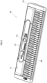
- An electronic keyboard instrument 10 (an electronic instrument), which is a sound generating device, shown FIG. 1 includes a 61-note keyboard 30 and an instrument case 19.
- a control section 31 including an adjustment control 13 is provided on an upper surface 11 of the electronic keyboard instrument 10.
- the instrument case 19 includes a rear panel 15, which is an external member, and a rear cover 12, which is disposed on an outer side of the rear panel 15.
- an up-down direction of the electronic keyboard instrument 10 is referred to as a Z-axis (a lower side is referred to as a positive side of the Z-axis), a left-right direction of the electronic keyboard instrument 10, which is a direction in which keys are aligned, is referred to as an X-axis (a high-note keys side is referred to as a positive side of the X-axis), and a front-rear direction of the electronic keyboard instrument 10, which is a front-rear direction of a key, is referred to a Y-axis (a nearer side of the key is referred to as a positive side of the Y-axis).
- Each first sound radiation section 100 has a frame portion 110 which includes multiple sound radiation holes 150
- each second sound radiation section 200 has a frame portion 210 which includes multiple sound radiation holes 250.
- the first sound radiation section 100 and the second sound radiation section 200 are disposed in series in a direction (an X-axis direction in FIG. 2 ) which is at right angles to an axial direction of the sound radiation holes 150, 250 (A Y-axis direction in FIG. 2 , that is, a thickness direction of the frame portions 110, 210) .
- the two first sound radiation sections 100 are disposed outwards at outer sides (sides farther away from the connector panel 18) of the electronic keyboard instrument 10 in the X-axis direction
- the two second sound radiation sections 200 are disposed inwards at inner sides (sides closer to the connector panel 18) of the electronic keyboard instrument 10 in the X-axis direction.
- the first sound radiation section 100 and the second sound radiation section 200 which make up a pair at a left side and the first sound radiation section 100 and the second sound radiation section 200 which make up a pair at a right side of the electronic keyboard instrument 10 are provided symmetrically with each other.
- a sound radiation apparatus 20 is provided on an inner side (the positive side of the Y-axis) of the rear panel 15 in such a manner as to correspond individually to the first sound radiation section 100 and the second sound radiation section 200.
- the sound radiation apparatus 20 is a speaker.
- the rear panel 15 (the first sound radiation sections 100, the second sound radiation sections 200) is disposed to lie close to the sound radiation apparatuses 20.
- the rear cover 12 is provided on the outer side of the rear panel 15. In the rear cover 12, portions corresponding to the first sound radiation sections 100 and the second sound radiation sections 200 are opened.
- a saran net can be provided on an outer surface of the rear cover 12.
- the frame portions 110, 210 are provided in such a manner that an external shape of an outer edge has a substantially oval shape whose major axis extends in the X-axis direction.
- the frame portions 110, 210 have multiple frames 115, 215, respectively.
- the frames 115, 215 denote sides making up, for example, the sound radiation holes 150, 250, respectively, which have a hexagonal shape.
- the sound radiation holes 150, 250 are provided by areas which are surrounded by the multiple frames 115, 215, respectively.
- surfaces (outer surfaces 110a, 210a) of outer sides (a negative side of the Y-axis direction) of the frame portions 110, 210 are formed flat and level with each other.
- the first sound radiation section 100 will be described. As shown in FIG. 3 , the sound radiation holes 150 provided in the frame portion 110 of the first sound radiation section 100 include multiple first sound radiation holes 160-1 to multiple sixth sound radiation holes 160-6, and multiple isomorphic sound radiation holes 170.
- the first sound radiation section 100 includes the multiple isomorphic sound radiation holes 170 which are provided on an inner side thereof (a side facing the connector panel 18) in a direction (the X-axis direction) which is at right angles to the thickness direction (the Y-axis direction) of the frame portion 110.
- the frame portion 110 of the first sound radiation section 100 includes straight-line frames 120-1 to 120-6, which are provided to extend long in a straight line.
- the straight-line frames 120-1 to 120-4 are provided to extend in the Z-axis direction in parallel to one another in such a manner as to be connected to the outer edge of the frame portion 110.
- the straight-line frames 120-1, 120-2 are provided to be spaced a predetermined distance apart from each other at a substantially central portion of the frame portion 110 in the X-axis direction, and the straight-line frame 120-1 is disposed inwards, while the straight-line frame 120-2 is disposed outwards.
- the straight-line frame 120-3 is disposed inwards of the straight-line frame 120-1 in the x-direction, while the straight-line frame 120-4 is disposed outwards of the straight-line frame 120-2 in the X-axis direction.
- the straight-line frame 120-4 also include a sloping portion (a second sloping portion 162b) at a portion which is superposed on one of sides of a second sound radiation hole 160-2 which form a hexagonal shape.
- the straight-line frames 120-5, 120-6 are provided to extend in the X-axis direction in parallel to each other in such a manner as to be connected to the outer edge of the frame portion 110.
- the straight-line frames 120-5, 120-6 are provided in the vicinity of lower and upper outer edges of the frame portion 110 in the Z-axis direction, respectively in such a manner that the straight-line frame 120-5 lies on a lower side, while the straight-line frame 120-6 lies on an upper side.
- the multiple polygonal or substantially hexagonal isomorphic sound radiation holes 170 are provided substantially into a honeycomb configuration at a portion of the frame portion 110 which lies inwards in the X-axis direction with respect to the straight-line frame 120-1, which is disposed at a central portion of the frame portion 110, and between the lower and upper straight-line frames 120-5, 120-6.
- the isomorphic sound radiation hole 170 is provided to have substantially the same shape at an inner side and an outer side thereof in an axial direction (the Y-axis direction) of the sound radiation hole 150.
- the isomorphic sound hole means a hole having substantially the same shape at an inner side and an outer side thereof in the axial direction (the Y-axis direction, that is, the thickness direction of the frame portion 110) of the sound radiation hole 150.
- the isomorphic sound radiation holes 170 which connect to the outer edge of the frame portion 110 or the straight-line frames 120-5, 120-6 are provided to have a deformed substantially hexagonal shape or a shape resulting when the substantially hexagonal shape is cut into halves.
- multiple polygonal or substantially hexagonal first sound radiation holes 160-1 to third sound radiation holes 160-3 are provided substantially into a honeycomb configuration at a portion of the frame portion 110 which lies outwards in the X-axis direction with respect to the straight-line frame 120-2 and between the straight-line frames 120-5, 120-6.
- the multiple first sound radiation holes 160-1 to third sound radiation holes 160-3 are each aligned in the X-axis direction, while being arranged in three rows in the Z-axis direction. Referring to FIG. 3 , the multiple first sound radiation holes 160-1 are aligned horizontally in an upper row, the multiple second sound radiation holes 160-2 are aligned horizontally in a middle row, and the multiple third sound radiation holes 160-3 are aligned horizontally in a lower row.
- sloping surfaces of the first sound radiation holes 160-1 to seventh sound radiation holes 160-7 are shown as being shaded.
- the first sound radiation hole 160-1 will be described by taking a first sound radiation hole 161 in the first sound radiation holes 160-1 which is shown in a sectional view in FIG. 5 for example.
- the first sound radiation hole 161 has a first sloping portion 161b including a first sloping surface 161a which is disposed to slope down from the thickness direction of the frame portion 110 which is an axial direction of the first sound radiation hole 161 (the Y-axis direction, that is, the thickness direction of the frame portion 110) within an area in the first sound radiation hole 161 (within an area inside the substantially hexagonal shape when seen from above in FIG. 3 ).
- a first direction 161c which is a sloping direction of the first sloping surface 161a (a direction at right angles to an edge line 161a1 of the first sloping surface 161a inside the hole, which is a direction directed from an inner side to an outer side of the first sound radiation hole 161, that is, a sound radiation direction), is a direction which divides an angle formed between a negative side of the X-axis and a negative side of the Z-axis substantially into half angles.
- a second sound radiation hole 160-2 will be described by taking a second sound radiation hole 162 shown in the sectional view in FIG. 4 for example.
- the second sound radiation hole 162 has a second sloping portion 162b including a second sloping surface 162a which is disposed to slope down from the thickness direction of the frame portion 110 which is an axial direction of the second sound radiation hole 162 (the Y-axis direction) within an area in the second sound radiation hole 162.
- a second direction 162c which is a sloping direction of the second sloping surface 162a, constitutes a direction of the negative side of the X-axis.
- a third sound radiation hole 160-3 (a third sound radiation hole 163) has a third sloping portion 163b including a third sloping surface 163a, and a third direction 163c, which is a sloping direction of the third sloping surface 163a, constitutes a direction which divides an angle formed between the negative side of the X-axis and a positive side of the Z-axis substantially into half angles.
- the first direction 161c, the second direction 162c, and the third direction 163c constitute different directions from one another.
- multiple quadrangular fourth sound radiation holes 160-4 and multiple quadrangular fifth sound radiation holes 160-5 are disposed on outer sides of the upper straight-line frame 120-6 and the lower straight-line frame 120-5, respectively.
- a fourth direction 164c which is a direction of the positive side of the Z-axis, constitutes a sloping direction of a fourth sloping surface 164a of a fourth sloping portion 164b.
- a fifth direction 165c which is a direction of the negative side of the Z-axis, constitutes a sloping direction of a fifth sloping surface 165a of a fifth sloping portion 165b.
- the fourth sloping portion 164b and the fifth sloping portion 165b include the sloping surfaces (the fourth sloping surface 164a, the fifth sloping surface 165a) which are both disposed to slope down from the thickness direction of the frame portion 110.
- an isomorphic sound radiation hole 172 is provided substantially at a central portion of the frame portion 110 which is defined between the central straight-line frames 120-1, 120-2 in the Z-axis direction and the X-axis direction.
- the sixth sound radiation hole 160-6 and the seventh sound radiation hole 160-7 which each have a substantially rectangular shape which is elongated in the Z-axis direction, are provided at an upper side (the negative side) and a lower side (the positive side) of the isomorphic sound radiation hole 172 in the Z-axis direction, respectively.
- a sixth sloping surface 166a of a sixth sloping portion 166b of the sixth sound radiation hole 160-6 is disposed to slope down from the thickness direction of the frame portion 110.
- the sixth sloping surface 166a is provided in such a manner as to expand from the inner side towards the outer side of the frame portion 110.
- the sixth sloping portion 166b includes a bent portion which is provided in such a manner as to be bent in the expanding direction.
- a seventh sloping surface 167a of a seventh sloping portion 167b of the seventh sound radiation hole 160-7 includes a bent portion, which is similar to that described above, and is disposed to slope down from the thickness direction of the frame portion 110.
- a sloping direction of the sixth sloping surface 166a of the sixth sound radiation hole 160-6 is the same as the fourth direction 164c.
- a sloping direction of the seventh sloping surface 167a of the seventh sound radiation hole 160-7 is the same as the fifth direction 165c.
- the sloping portions (the sixth sloping portion 166b and the seventh sloping portion 167b) which include the sloping surfaces (the sixth sloping surface 166a and the seventh sloping surface 167a) are both provided between second hole frames 112, which will be described later.
- the sloping portions (the sixth sloping portion 166b and the seventh sloping portion 167b) are provided to make a pair so that the sloping surfaces (the sixth sloping surface 166a and the seventh sloping surface 167a) face each other.
- the sound radiation directions from the first sound radiation section 100 include a right-upward direction (the first direction 161c) defined by the first sound radiation hole 160-1, a rightward direction (the second direction 162c) defined by the second sound radiation hole 160-2, a right-downward direction (the third direction 163c) defined by the third sound radiation hole 160-3, an upward direction (the fourth direction 164c) defined by the fourth sound radiation hole 160-4 and the sixth sound radiation hole 160-6, and a downward direction (the fifth direction 165c) defined by the fifth sound radiation hole 160-5 and the seventh sound radiation hole 160-7.
- sounds radiated from the first sound radiation section 100 can spread widely.
- the multiple frames 115 which make up the frame portion 110 of the first sound radiation section100 include first hole frames 111 and second hole frames 112 which include hole forming surfaces which define a sound radiation hole 150. As shown in FIG. 7A , which is an enlarged view of a portion P in FIG.
- an isomorphic sound radiation hole 171 is made up of respective hole forming surfaces 111a of six first hole frames 111 (denoted by reference signs a to f).
- an isomorphic sound radiation hole 172 is made up of respective hole forming surfaces 112a of six second hole frames 112 (denoted by reference signs g to 1).
- the hole forming surfaces 111a, 112a are side surfaces of a hole which extends in the thickness direction of the frame portion 110 (the Y-axis direction).
- a length of the hole forming surface is considered based on the thickness direction of the frame portion 110, even though the hole forming surface is shaped to expand as it extends.
- a length T2 of the hole forming surface 112a of the second hole frame 112 in the Y-axis direction of the isomorphic sound radiation hole 172 (the thickness direction of the frame portion 110) is longer than a length T1 of the hole forming surface 111a of the first hole frame 111 of the isomorphic sound radiation hole 111a in the thickness direction of the frame portion 110. Since the outer surface 110a of the frame portion 110 is formed into a flat plane, an inner surface 110b of a central portion of the frame portion 110 is made to protrude at the location of the second hole frame 112. As shown in FIG.
- the second hole frame 112 can be provided in such a manner as to correspond to a central recessed portion of a speaker cone 21 of the sound radiation apparatus 20.
- the second hole frame 112 includes a portion which is situated in an interior portion of the speaker cone 21.
- the first hole frame 111 is not situated in the interior portion of the speaker cone 21.
- Sound radiation holes 250 provided in the frame portion 210 of the second sound radiation section 200 are made up of multiple isomorphic sound radiation holes 270.
- the second sound radiation section 200 includes the frame portion 210 having sound radiation holes 250 which are made up of the isomorphic sound radiation holes 270 in place of the multiple sound radiation holes 150 including the first sound radiation hole 160-1 to the seventh sound radiation hole 160-7 of the first sound radiation section 100.
- the multiple isomorphic sound radiation holes 270 each have a polygonal or hexagonal shape and are formed substantially into a honeycomb configuration. Additionally, as with the first sound radiation section 100, straight-line frames 220-1 to 220-6 are provided in the frame portion 210 of the second sound radiation section 200.
- frames 215 of the second sound radiation section 200 include first frames 211 and second frames 212 which include hole forming surfaces 211a, 212a of sound radiation holes 250, respectively.
- a length T4 of the hole forming surface 212a of the second hole frame 212 in an axial direction of the sound radiation hole 250 is longer than a length T3 of the hole forming surface 211a of the first hole frame 211 in the thickness direction of the frame portion 210 (the Y-axis direction).
- the length T4 is shorter than the length T2.
- the second hole frame 112 is given the protruding shape, when seen from the side, with a view to spreading sounds as by the sixth sound radiation hole 160-6 and the seventh sound radiation hole 160-7, the sloping surface is provided long, which results in the fact that the length T2 is made relatively long.
- the frame 215 of the second sound radiation section 200 does not have to spread sounds from the viewpoint of sound characteristics, the length T4 is made shorter than the length T2.
- the disposition of the frame portions 110, 210 is not limited to the application example, and hence, the frame portions 110, 210 can be disposed differently and the lengths T2, T4 can also be changed in accordance with a desired sound characteristic.
- a predetermined area Q lying substantially at a central portion of the frame portion 210 is made up of the second hole frames 212 so as to increase the strength of the frame portion 210.
- the second hole frames 212 can be provided in such a manner as to correspond to the central recessed portion of the speaker cone 21.
- the rear panel 15 is molded from a resin through injection molding. As this occurs, a draft expanding from the outer side towards the inner side of the rear panel 15 is provided on hole forming surfaces of the sound radiation holes 150, 250. For example, as shown in FIGS. 7B and 8 , a draft is provided on the hole forming surfaces 111a, 112a, 211a, 212a as a result of the hole forming surfaces 111a, 112a, 211a, 212a expanding slightly from the outer side towards the inner side of the rear panel 15.
- a mold 50 for molding the rear panel 15 has a cavity mold 51 and a core mold 52.
- shaded portions constitute surfaces to be molded by the cavity mold 51, while blank or white portions constitute surfaces to be molded by the core mold 52.
- Four bosses 15a for attachment of the rear cover 12 are provided on an outer circumference of a front side (an outer side) of the first sound radiation section 100.
- a boss 15b for connection with the instrument case 19 of the electronic keyboard instrument 10 is provided on a circumference of a rear side (an inner side) of the first sound radiation section 100.
- hexagonal holes can be molded by providing hexagonal prism-like projections on the core mold 52 .
- the cavity mold 51 and the core mold 52 are configured as below.
- Hexagonal prisms 53 including corresponding sloping surfaces 51a, 52a which slope in the same direction on facing side surfaces thereof are provided on the mold 50 in such a manner that a pin 51b, which constitutes one side or part of the hexagonal prism 53 when the hexagonal prism 53 is divided along a line connecting facing apex portions M1, M2 thereof, is provided on the cavity mold 51 and a pin 52b, which is made up of the other side or part of the hexagonal prism 53 so divided, is provided on the core mold 52.
- a molding method of the rear panel 15, which constitutes the external member, using this mold 50 includes clamping the mold 50 and injecting a molten resin into the mold 50 so clamped. Then, a frame portion 110 including a first sound radiation hole 160-1 to a third sound radiation hole 160-3 in which sloping surfaces (a first sloping surface 161a and the like) are provided within hole areas thereof is molded by the hexagonal prisms 53.
- the line connecting the facing apex portions M1, M2 of the hexagonal shape constitutes a parting line PL.
- FIGS. 7A, 7B show a circumferential area of the isomorphic sound radiation holes 171, 172 of the first sound radiation section 100.
- the core mold 52 of the mold 50 includes the first pin 52c corresponding to the hole forming surface 111a of the first hole frame 111 and the second pin 52d corresponding to the hole forming surface 112a of the second hole frame 112.
- the molding method of the rear panel 15 using the mold 50 similarly includes clamping the mold 50 and injecting a molten resin thereinto.
- a frame portion 110 is molded which includes multiple sound radiation holes 150 including first hole frames 111 and second hole frames 112.
- FIGS. 7A and 7B illustrate the first sound radiation section 100
- what is illustrated therein can also equally be applied to the first hole frames 211 and the second hole frames 212 of the second sound radiation section 200.
- the rear panel 15, which is the external member, has the frame portion 110 including the multiple sound holes 150 including the first sound radiation hole 160-1 and the second sound radiation hole 160-2, the first sloping portion 161b disposed within the area of the first sound radiation hole 160-1 in such a manner as to be disposed in the frame portion 110 with the first sloping surface 161a, which is disposed to slope from the thickness direction of the frame portion 110 (the Y-axis direction), oriented in the first direction 161c, and the second sloping portion 162b disposed within the area of the second sound radiation hole 160-2 with the second sloping surface 162a oriented in the second direction 162c which differs from the first direction 161c.
- the frame portion 110 has the first sound radiation hole 160-1 to the fourth sound radiation hole 160-4 whose sound radiation directions (the first direction 161c to the fourth direction 164c) differ from one another.
- the sound radiation directions (the first direction 161c to the fourth direction 164c) can be set freely by disposing the sloping surfaces (the first sloping surface 161a to the fourth sloping surface 164a) of the sloping portions (the first sloping portion 161b to the fourth sloping portion 164b) within the sound radiation holes 150 (the first sound radiation hole 160-1 to the fourth sound radiation hole 160-4) as required.
- the sound radiation holes 150 the first sound radiation hole 160-1 to the fourth sound radiation hole 160-4
- the sloping portions (the first sloping portion 161b and the second sloping portion 162b) can be provided in such a manner as to extend over the sides of the polygonal shape, whereby the sound radiation directions can be set more easily.
- the sound radiation directions can be set in the six directions.
- the sound radiation holes 150 of the frame portion 110 include the fourth sound radiation hole 160-4 and the fifth sound radiation hole 160-5, which constitute the quadrangular sound radiation holes 150, and the sloping portions (the fourth sloping portion 164b, the fifth sloping portion 165b) including the sloping surfaces (the fourth sloping surface 164a, the fifth sloping surface 165a) which are disposed in such a manner as to slope from the thickness direction of the frame portion 110 (the Y-axis direction) are provided within the areas of the fourth sound radiation hole 160-4 and the fifth sound radiation hole 160-5 while being oriented in the directions which differ from the first direction 161c and the second direction 162c.
- the rear panel 15 can be provided which constitutes the external member which enables sounds to be radiated more widely in terms of sound radiation direction.
- the multiple sound radiation holes 150 including the first sound radiation hole 160-1 and the second sound radiation hole 160-2 in particular, the multiple first sound radiation holes 160-1 to the multiple third sound radiation holes 160-3, and the isomorphic sound radiation holes 170 are each disposed into the honeycomb configuration. As a result, the frame portion 110 having the high strength can be provided.
- the rear panel 15 which is the external member, has the first sound radiation section 100 including the frame portion 110 made up of the sound radiation holes 150 including the multiple first sound radiation holes 160-1 and the multiple second sound radiation holes 160-2, and the multiple isomorphic sound radiation holes 170 and the second sound radiation section 200 including the second frame portion 210 made up of the isomorphic sound radiation holes 270 in place of the multiple sound radiation holes 150 including the first sound radiation holes 160-1 and the second sound radiation holes 160-2.
- the rear panel 15 can be provided which includes the first sound radiation section 100 configured to radiate sounds widely and the sound radiation holes 250 made up of the isomorphic sound radiation holes 270 configured to radiate dynamic sounds by radiating sounds without closing the sound radiation holes 250.
- the two first sound radiation sections 100 are disposed outwards in the direction (the X-axis direction) which is at right angles to the thickness direction of the frame portions 110, 210 (the Y-axis direction), and the two sound radiation sections 200 are disposed inwards of the corresponding first sound radiation sections 100 in the X-axis direction.
- the first sound radiation sections 100 which are configured to radiate sounds widely, can be allowed to radiate sounds with good efficiency.
- the first sound radiation section 100 includes the isomorphic sound radiation holes which are provided at the half portion thereof which lies inwards in the direction which is at right angles to the thickness direction of the frame portion 110.
- the first sound radiation holes 160-1, the second sound radiation holes 160-2, and the like can be provided outwards, and this configuration can reduce the possibility of sounds spreading outwards interfering with sounds radiated in a straight line in the Y-axis direction.
- the frame portions 110, 210 are formed into the oval shape as the external shape of the outer edge thereof. As a result, even though the housing of the electronic keyboard instrument 10 is configured small in size by use of the sound radiation apparatus 20 as a speaker having an oval shape, the rear panel 15 can still radiate sounds which spread widely.
- the frame portions 110, 210 are provided to have the oval shape as the external shape of the outer edge thereof. As a result, even though a speaker having an oval shape is installed in a small electronic keyboard instrument, the external member can still radiate sounds which spread widely.
- the rear panel 15 is provided in the electronic keyboard instrument 10 as an electronic instrument.
- sounds can be radiated so as to spread widely.
- the molding method of the rear panel 15 includes clamping the mold 50 having the cavity mold 51 including the pins 51b each constituting the one side or part of the hexagonal prism which results from dividing the hexagonal prism between the pair of sloping surfaces 51a, 52a formed on the facing sides thereof in such a manner as to slope in the same direction along the line connecting the facing apex portions M1, M2 of the hexagonal prism and the core mold 52 including the pins 52 each constituting the other side or part of the hexagonal prism so divided, and molding the frame portion 110 including the sound radiation holes 150 (the first sound radiation holes 160-1 and the like) including the sloping surfaces (the first sloping surface 161a and the like) formed within the areas of the holes (the first sound radiation holes 160-1 and the like) by injecting a molten resin into the mold 50.
- the lines connecting the facing apex portions of the hexagonal sound radiation holes 150 can be made to constitute the parting lines, whereby the cavity mold 51 and the core mold 52 can be provided without making the structure of the mold 50 complex.
Landscapes
- Engineering & Computer Science (AREA)
- Physics & Mathematics (AREA)
- Acoustics & Sound (AREA)
- Signal Processing (AREA)
- Multimedia (AREA)
- Health & Medical Sciences (AREA)
- Otolaryngology (AREA)
- Electrophonic Musical Instruments (AREA)
- Details Of Audible-Bandwidth Transducers (AREA)
- Casings For Electric Apparatus (AREA)
- Obtaining Desirable Characteristics In Audible-Bandwidth Transducers (AREA)
Abstract
A rear panel 15, which is an external member, includes a frame portion 110 including multiple sound radiation holes 150 including a first sound radiation hole 160-1 and a second sound radiation hole 160-2, a first sloping portion 160b disposed in the frame portion 110 with a first sloping surface 161a oriented in a first direction 161c, the sloping surface 161a being disposed within an area of the first sound radiation hole 160-1 in such a manner as to slope from a thickness direction (a Y-axis direction) of the frame portion 110, and a second sloping portion 162b disposed in the frame portion 110 with a sloping surface 162a oriented in a second direction 162c which differs from the first direction 161c, the sloping surface 162a being disposed within an area of the second sound radiation hole 160-2 in such a manner as to slope from the thickness direction (the Y-axis direction) of the frame portion 110.
Description
- This patent application is based upon and claims the benefit of priority under 35 USC 119 to
Japanese Patent Application No. 2021-207674 filed on December 22, 2021 - The present disclosure relates to an external member, an external member molding method, and an electronic instrument.
- An external member including multiple sound radiation holes like a speaker cover or net has conventionally been used for a sound generating or radiation device such as an electronic instrument or a radio. For example,
JP-UM-A-6-62693 - According to an aspect of the present disclosure, there is provided an external member having a frame portion including multiple sound radiation holes including a first sound radiation hole and a second sound radiation hole, a first sloping portion disposed in the frame portion with a sloping surface oriented in a first direction, the sloping surface being disposed within an area of the first sound radiation hole in such a manner as to slope from a thickness direction of the frame portion, and a second sloping portion disposed in the frame portion with a sloping surface oriented in a second direction which differs from the first direction, the sloping surface being disposed within an area of the second sound radiation hole in such a manner as to slope from the thickness direction of the frame portion.
- According to another aspect of the present disclosure, there is provided an electronic instrument including the external cover described above.
- According to a further aspect of the present disclosure, there is provided an external member molding method including clamping a mold having a cavity mold including one side of a hexagonal prism including a pair of sloping surfaces formed on facing side surfaces thereof in such a manner as to slope in an identical direction, the one side of the hexagonal prism resulting from dividing the hexagonal prism along a line connecting facing apex portions of the hexagonal prism, and a core mold including a remaining side of the hexagonal prism so divided, and molding a frame portion including a sound radiation hole including a sloping surface within an area of the hole by the hexagonal prism by injecting a molten resin into the mold.
-
-
FIG. 1 is a perspective view of an electronic keyboard instrument including an external member (a rear panel) according to an embodiment or application example of the present disclosure; -
FIG. 2 is a rear view of the electronic keyboard instrument including the external member (the rear panel) according to the application example of the present disclosure; -
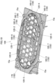
FIG. 3 is an enlarged rear view of the electronic keyboard instrument, showing a first sound radiation section and a second sound radiation section which are provided in the external member (the rear panel) according to the application example of the present disclosure; -
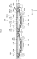
FIG. 4 is a sectional view of the external member (the rear panel) according to the application example of the present disclosure taken along a line IV-IV inFIG. 3 ; -
FIG. 5 is a sectional view of the external member (the rear panel) according to the application example of the present disclosure taken along a line V-V inFIG. 3 ; -
FIG. 6 is a sectional view of the external member (the rear panel) according to the application example of the present disclosure taken along a line VI-VI inFIG. 3 ; -
FIG. 7A is an enlarged rear view, which is a partially enlarged view of isomorphic sound radiation portions of the second sound radiation section in the external member (the rear panel) according to the application example of the present disclosure; -
FIG. 7B is a sectional view taken along a line VIIb-VIIb inFIG. 7A , which is a partially enlarged view of the isomorphic sound radiation portions of the second sound radiation section in the external member (the rear panel) according to the application example of the present disclosure; -
FIG. 8 is a sectional view of the external member (the rear panel) according to the application example of the present disclosure taken along a line VIII-VIII inFIG. 3 ; -
FIG. 9 is a perspective view of the second sound radiation section of the external member (the rear panel) according to the application example of the present disclosure as seen from an inner side thereof; -
FIG. 10 is a perspective view of the first sound radiation section of the external member (the rear panel) according to the application example of the present disclosure as seen from a front side (an outer side) thereof, in which surfaces to be molded by a core mold are shown as left blank or white, while surfaces to be molded by a cavity mold are shown as shaded; -
FIG. 11 is a perspective view of the first sound radiation section of the external member (the rear panel) according to the application example of the present disclosure as seen from a rear side (an inner side) thereof, in which surfaces to be molded by the core mold are shown as left blank or white, while surfaces to be molded by the cavity mold are shown as shaded; -
FIG. 12A is an explanatory diagram of a mold for molding the external member (the rear panel) according to the application example of the present disclosure, which is an enlarged rear view of a front side (an outer side) of the second sound radiation hole in the rear panel, which constitutes a product molded by the mold; and -
FIG. 12B is an explanatory diagram of the mold for molding the external member (the rear panel) according to the application example of the present disclosure, which is a sectional view of the mold corresponding to a sectional view taken along a line XIIb-XIIb inFIG. 12A . - Hereinafter, referring to accompanying drawings, an embodiment or application example of the present disclosure will be described. An electronic keyboard instrument 10 (an electronic instrument), which is a sound generating device, shown
FIG. 1 includes a 61-note keyboard 30 and aninstrument case 19. Acontrol section 31 including anadjustment control 13 is provided on anupper surface 11 of theelectronic keyboard instrument 10. As shown inFIG. 2 , theinstrument case 19 includes arear panel 15, which is an external member, and arear cover 12, which is disposed on an outer side of therear panel 15. Aconnector panel 18, which includes a connection port for an AC adaptor, connection ports for other sound generating or radiation devices, and USB connection ports, is provided at a central portion of a lower part of therear panel 15 of the electronickeyboard instrument panel 10. - In the following description, an up-down direction of the
electronic keyboard instrument 10 is referred to as a Z-axis (a lower side is referred to as a positive side of the Z-axis), a left-right direction of theelectronic keyboard instrument 10, which is a direction in which keys are aligned, is referred to as an X-axis (a high-note keys side is referred to as a positive side of the X-axis), and a front-rear direction of theelectronic keyboard instrument 10, which is a front-rear direction of a key, is referred to a Y-axis (a nearer side of the key is referred to as a positive side of the Y-axis). - Two first
sound radiation sections 100 and two secondsound radiation sections 200 are provided in therear panel 15 of theelectronic keyboard instrument 10. Each firstsound radiation section 100 has aframe portion 110 which includes multiplesound radiation holes 150, and each secondsound radiation section 200 has aframe portion 210 which includes multiplesound radiation holes 250. The firstsound radiation section 100 and the secondsound radiation section 200 are disposed in series in a direction (an X-axis direction inFIG. 2 ) which is at right angles to an axial direction of thesound radiation holes 150, 250 (A Y-axis direction inFIG. 2 , that is, a thickness direction of theframe portions 110, 210) . Then, the two firstsound radiation sections 100 are disposed outwards at outer sides (sides farther away from the connector panel 18) of theelectronic keyboard instrument 10 in the X-axis direction, and the two secondsound radiation sections 200 are disposed inwards at inner sides (sides closer to the connector panel 18) of theelectronic keyboard instrument 10 in the X-axis direction. The firstsound radiation section 100 and the secondsound radiation section 200 which make up a pair at a left side and the firstsound radiation section 100 and the secondsound radiation section 200 which make up a pair at a right side of theelectronic keyboard instrument 10 are provided symmetrically with each other. - As shown in
FIG. 4 , asound radiation apparatus 20 is provided on an inner side (the positive side of the Y-axis) of therear panel 15 in such a manner as to correspond individually to the firstsound radiation section 100 and the secondsound radiation section 200. In the present application example, thesound radiation apparatus 20 is a speaker. The rear panel 15 (the firstsound radiation sections 100, the second sound radiation sections 200) is disposed to lie close to thesound radiation apparatuses 20. Therear cover 12 is provided on the outer side of therear panel 15. In therear cover 12, portions corresponding to the firstsound radiation sections 100 and the secondsound radiation sections 200 are opened. Although not shown, a saran net can be provided on an outer surface of therear cover 12. - As shown in
FIG. 3 , theframe portions frame portions multiple frames frames sound radiation holes sound radiation holes multiple frames FIG. 4 , surfaces (outer surfaces frame portions - The first
sound radiation section 100 will be described. As shown inFIG. 3 , thesound radiation holes 150 provided in theframe portion 110 of the firstsound radiation section 100 include multiple first sound radiation holes 160-1 to multiple sixth sound radiation holes 160-6, and multiple isomorphicsound radiation holes 170. The firstsound radiation section 100 includes the multiple isomorphicsound radiation holes 170 which are provided on an inner side thereof (a side facing the connector panel 18) in a direction (the X-axis direction) which is at right angles to the thickness direction (the Y-axis direction) of theframe portion 110. Theframe portion 110 of the firstsound radiation section 100 includes straight-line frames 120-1 to 120-6, which are provided to extend long in a straight line. The straight-line frames 120-1 to 120-4 are provided to extend in the Z-axis direction in parallel to one another in such a manner as to be connected to the outer edge of theframe portion 110. The straight-line frames 120-1, 120-2 are provided to be spaced a predetermined distance apart from each other at a substantially central portion of theframe portion 110 in the X-axis direction, and the straight-line frame 120-1 is disposed inwards, while the straight-line frame 120-2 is disposed outwards. - The straight-line frame 120-3 is disposed inwards of the straight-line frame 120-1 in the x-direction, while the straight-line frame 120-4 is disposed outwards of the straight-line frame 120-2 in the X-axis direction. The straight-line frame 120-4 also include a sloping portion (a second sloping
portion 162b) at a portion which is superposed on one of sides of a second sound radiation hole 160-2 which form a hexagonal shape. The straight-line frames 120-5, 120-6 are provided to extend in the X-axis direction in parallel to each other in such a manner as to be connected to the outer edge of theframe portion 110. The straight-line frames 120-5, 120-6 are provided in the vicinity of lower and upper outer edges of theframe portion 110 in the Z-axis direction, respectively in such a manner that the straight-line frame 120-5 lies on a lower side, while the straight-line frame 120-6 lies on an upper side. - The multiple polygonal or substantially hexagonal isomorphic sound radiation holes 170 are provided substantially into a honeycomb configuration at a portion of the
frame portion 110 which lies inwards in the X-axis direction with respect to the straight-line frame 120-1, which is disposed at a central portion of theframe portion 110, and between the lower and upper straight-line frames 120-5, 120-6. As shown inFIG. 4 , the isomorphicsound radiation hole 170 is provided to have substantially the same shape at an inner side and an outer side thereof in an axial direction (the Y-axis direction) of thesound radiation hole 150. Here, when referred to in relation theisomorphic sound holes sound radiation hole 150. The isomorphic sound radiation holes 170 which connect to the outer edge of theframe portion 110 or the straight-line frames 120-5, 120-6 are provided to have a deformed substantially hexagonal shape or a shape resulting when the substantially hexagonal shape is cut into halves. - On the other hand, multiple polygonal or substantially hexagonal first sound radiation holes 160-1 to third sound radiation holes 160-3 are provided substantially into a honeycomb configuration at a portion of the
frame portion 110 which lies outwards in the X-axis direction with respect to the straight-line frame 120-2 and between the straight-line frames 120-5, 120-6. The multiple first sound radiation holes 160-1 to third sound radiation holes 160-3 are each aligned in the X-axis direction, while being arranged in three rows in the Z-axis direction. Referring toFIG. 3 , the multiple first sound radiation holes 160-1 are aligned horizontally in an upper row, the multiple second sound radiation holes 160-2 are aligned horizontally in a middle row, and the multiple third sound radiation holes 160-3 are aligned horizontally in a lower row. Here, inFIG. 3 , sloping surfaces of the first sound radiation holes 160-1 to seventh sound radiation holes 160-7 are shown as being shaded. - The first sound radiation hole 160-1 will be described by taking a first
sound radiation hole 161 in the first sound radiation holes 160-1 which is shown in a sectional view inFIG. 5 for example. The firstsound radiation hole 161 has a firstsloping portion 161b including a firstsloping surface 161a which is disposed to slope down from the thickness direction of theframe portion 110 which is an axial direction of the first sound radiation hole 161 (the Y-axis direction, that is, the thickness direction of the frame portion 110) within an area in the first sound radiation hole 161 (within an area inside the substantially hexagonal shape when seen from above inFIG. 3 ). Afirst direction 161c, which is a sloping direction of the firstsloping surface 161a (a direction at right angles to an edge line 161a1 of the firstsloping surface 161a inside the hole, which is a direction directed from an inner side to an outer side of the firstsound radiation hole 161, that is, a sound radiation direction), is a direction which divides an angle formed between a negative side of the X-axis and a negative side of the Z-axis substantially into half angles. - Similarly, a second sound radiation hole 160-2 will be described by taking a second
sound radiation hole 162 shown in the sectional view inFIG. 4 for example. The secondsound radiation hole 162 has a secondsloping portion 162b including a secondsloping surface 162a which is disposed to slope down from the thickness direction of theframe portion 110 which is an axial direction of the second sound radiation hole 162 (the Y-axis direction) within an area in the secondsound radiation hole 162. Then, asecond direction 162c, which is a sloping direction of the secondsloping surface 162a, constitutes a direction of the negative side of the X-axis. - Also, similarly, a third sound radiation hole 160-3 (a third sound radiation hole 163) has a third
sloping portion 163b including a thirdsloping surface 163a, and athird direction 163c, which is a sloping direction of the thirdsloping surface 163a, constitutes a direction which divides an angle formed between the negative side of the X-axis and a positive side of the Z-axis substantially into half angles. Thefirst direction 161c, thesecond direction 162c, and thethird direction 163c constitute different directions from one another. - On the other hand, multiple quadrangular fourth sound radiation holes 160-4 and multiple quadrangular fifth sound radiation holes 160-5 are disposed on outer sides of the upper straight-line frame 120-6 and the lower straight-line frame 120-5, respectively. In the fourth sound radiation hole 160-4 (a fourth sound radiation hole 164), a
fourth direction 164c, which is a direction of the positive side of the Z-axis, constitutes a sloping direction of a fourthsloping surface 164a of a fourthsloping portion 164b. In the fifth sound radiation hole 160-5 (a fifth sound radiation hole 165), afifth direction 165c, which is a direction of the negative side of the Z-axis, constitutes a sloping direction of a fifthsloping surface 165a of a fifthsloping portion 165b. The fourthsloping portion 164b and the fifth slopingportion 165b include the sloping surfaces (the fourthsloping surface 164a, the fifthsloping surface 165a) which are both disposed to slope down from the thickness direction of theframe portion 110. - Also, on the other hand, an isomorphic
sound radiation hole 172 is provided substantially at a central portion of theframe portion 110 which is defined between the central straight-line frames 120-1, 120-2 in the Z-axis direction and the X-axis direction. The sixth sound radiation hole 160-6 and the seventh sound radiation hole 160-7, which each have a substantially rectangular shape which is elongated in the Z-axis direction, are provided at an upper side (the negative side) and a lower side (the positive side) of the isomorphicsound radiation hole 172 in the Z-axis direction, respectively. - As shown in
FIG. 6 , a sixthsloping surface 166a of a sixthsloping portion 166b of the sixth sound radiation hole 160-6 is disposed to slope down from the thickness direction of theframe portion 110. In other words, the sixthsloping surface 166a is provided in such a manner as to expand from the inner side towards the outer side of theframe portion 110. The sixthsloping portion 166b includes a bent portion which is provided in such a manner as to be bent in the expanding direction. Similarly, a seventhsloping surface 167a of a seventhsloping portion 167b of the seventh sound radiation hole 160-7 includes a bent portion, which is similar to that described above, and is disposed to slope down from the thickness direction of theframe portion 110. A sloping direction of the sixthsloping surface 166a of the sixth sound radiation hole 160-6 is the same as thefourth direction 164c. A sloping direction of the seventhsloping surface 167a of the seventh sound radiation hole 160-7 is the same as thefifth direction 165c. The sloping portions (the sixth slopingportion 166b and the seventh slopingportion 167b) which include the sloping surfaces (the sixthsloping surface 166a and the seventhsloping surface 167a) are both provided between second hole frames 112, which will be described later. Then, the sloping portions (the sixth slopingportion 166b and the seventh slopingportion 167b) are provided to make a pair so that the sloping surfaces (the sixthsloping surface 166a and the seventhsloping surface 167a) face each other. - In this way, as shown in
FIG. 3 , the sound radiation directions from the firstsound radiation section 100 include a right-upward direction (thefirst direction 161c) defined by the first sound radiation hole 160-1, a rightward direction (thesecond direction 162c) defined by the second sound radiation hole 160-2, a right-downward direction (thethird direction 163c) defined by the third sound radiation hole 160-3, an upward direction (thefourth direction 164c) defined by the fourth sound radiation hole 160-4 and the sixth sound radiation hole 160-6, and a downward direction (thefifth direction 165c) defined by the fifth sound radiation hole 160-5 and the seventh sound radiation hole 160-7. As a result, sounds radiated from the firstsound radiation section 100 can spread widely. - Also, here, heights (length in the thickness direction of the frame portion 110 (the Y-axis direction)) of the
multiple frames 115 which make up theframe portion 110 of the firstsound radiation section 100 will be considered. This will be described by taking isomorphic sound radiation holes 171, 172 shown inFIGS. 7A and 7B for example. Themultiple frames 115 which make up theframe portion 110 of the first sound radiation section100 include first hole frames 111 and second hole frames 112 which include hole forming surfaces which define asound radiation hole 150. As shown inFIG. 7A , which is an enlarged view of a portion P inFIG. 3 , an isomorphicsound radiation hole 171 is made up of respectivehole forming surfaces 111a of six first hole frames 111 (denoted by reference signs a to f). Similarly, an isomorphicsound radiation hole 172 is made up of respectivehole forming surfaces 112a of six second hole frames 112 (denoted by reference signs g to 1). Here, thehole forming surfaces frame portion 110, even though the hole forming surface is shaped to expand as it extends. - Then, as shown in
FIG. 7B , a length T2 of thehole forming surface 112a of thesecond hole frame 112 in the Y-axis direction of the isomorphic sound radiation hole 172 (the thickness direction of the frame portion 110) is longer than a length T1 of thehole forming surface 111a of thefirst hole frame 111 of the isomorphicsound radiation hole 111a in the thickness direction of theframe portion 110. Since theouter surface 110a of theframe portion 110 is formed into a flat plane, aninner surface 110b of a central portion of theframe portion 110 is made to protrude at the location of thesecond hole frame 112. As shown inFIG. 4 , thesecond hole frame 112 can be provided in such a manner as to correspond to a central recessed portion of aspeaker cone 21 of thesound radiation apparatus 20. Here, thesecond hole frame 112 includes a portion which is situated in an interior portion of thespeaker cone 21. Thefirst hole frame 111 is not situated in the interior portion of thespeaker cone 21. - Subsequently, the second
sound radiation section 200 will be described. Sound radiation holes 250 provided in theframe portion 210 of the secondsound radiation section 200 are made up of multiple isomorphic sound radiation holes 270. In other words, the secondsound radiation section 200 includes theframe portion 210 having sound radiation holes 250 which are made up of the isomorphic sound radiation holes 270 in place of the multiple sound radiation holes 150 including the first sound radiation hole 160-1 to the seventh sound radiation hole 160-7 of the firstsound radiation section 100. The multiple isomorphic sound radiation holes 270 each have a polygonal or hexagonal shape and are formed substantially into a honeycomb configuration. Additionally, as with the firstsound radiation section 100, straight-line frames 220-1 to 220-6 are provided in theframe portion 210 of the secondsound radiation section 200. - Next, as shown in
FIG. 9 , frames 215 of the secondsound radiation section 200 includefirst frames 211 andsecond frames 212 which includehole forming surfaces FIG. 8 , a length T4 of thehole forming surface 212a of thesecond hole frame 212 in an axial direction of the sound radiation hole 250 (the Y-axis direction, a thickness direction of the frame portion 210) is longer than a length T3 of thehole forming surface 211a of thefirst hole frame 211 in the thickness direction of the frame portion 210 (the Y-axis direction). In addition, the length T4 is shorter than the length T2. - Since the
second hole frame 112 is given the protruding shape, when seen from the side, with a view to spreading sounds as by the sixth sound radiation hole 160-6 and the seventh sound radiation hole 160-7, the sloping surface is provided long, which results in the fact that the length T2 is made relatively long. On the other hand, since theframe 215 of the secondsound radiation section 200 does not have to spread sounds from the viewpoint of sound characteristics, the length T4 is made shorter than the length T2. The disposition of theframe portions frame portions - In the second
sound radiation section 200, a predetermined area Q lying substantially at a central portion of theframe portion 210 is made up of the second hole frames 212 so as to increase the strength of theframe portion 210. In addition, as shown inFIG. 4 , the second hole frames 212 can be provided in such a manner as to correspond to the central recessed portion of thespeaker cone 21. - Here, the
rear panel 15 is molded from a resin through injection molding. As this occurs, a draft expanding from the outer side towards the inner side of therear panel 15 is provided on hole forming surfaces of the sound radiation holes 150, 250. For example, as shown inFIGS. 7B and8 , a draft is provided on thehole forming surfaces hole forming surfaces rear panel 15. - A
mold 50 for molding therear panel 15 has acavity mold 51 and acore mold 52. InFIGS. 10 ,11 showing the firstsound radiation section 100, shaded portions (a front side of the rear panel 15) constitute surfaces to be molded by thecavity mold 51, while blank or white portions constitute surfaces to be molded by thecore mold 52. Fourbosses 15a for attachment of therear cover 12 are provided on an outer circumference of a front side (an outer side) of the firstsound radiation section 100. Then, as shown inFIG. 11 , aboss 15b for connection with theinstrument case 19 of theelectronic keyboard instrument 10 is provided on a circumference of a rear side (an inner side) of the firstsound radiation section 100. - In molding hexagonal holes in the isomorphic sound radiation holes 170, 270, hexagonal holes can be molded by providing hexagonal prism-like projections on the
core mold 52 . In molding the first sound radiation hole 160-1 to the third sound radiation hole 160-3, since the sloping portions (the first slopingportion 161b to the thirdsloping portion 163b) are provided in the first to third sound radiation holes 160-1 to 160-3, thecavity mold 51 and thecore mold 52 are configured as below. -
Hexagonal prisms 53 including correspondingsloping surfaces mold 50 in such a manner that apin 51b, which constitutes one side or part of thehexagonal prism 53 when thehexagonal prism 53 is divided along a line connecting facing apex portions M1, M2 thereof, is provided on thecavity mold 51 and apin 52b, which is made up of the other side or part of thehexagonal prism 53 so divided, is provided on thecore mold 52. - A molding method of the
rear panel 15, which constitutes the external member, using thismold 50 includes clamping themold 50 and injecting a molten resin into themold 50 so clamped. Then, aframe portion 110 including a first sound radiation hole 160-1 to a third sound radiation hole 160-3 in which sloping surfaces (a firstsloping surface 161a and the like) are provided within hole areas thereof is molded by thehexagonal prisms 53. - In this way, in the
cavity mold 51 and thecore mold 52 for molding the first sound radiation hole 160-1 to the third sound radiation hole 160-3, the line connecting the facing apex portions M1, M2 of the hexagonal shape constitutes a parting line PL. - Further, a molding method of the first hole frames 111, 211 and the second hole frames 112, 212 will be described using
FIGS. 7A, 7B , which show a circumferential area of the isomorphic sound radiation holes 171, 172 of the firstsound radiation section 100. As shown inFIG. 7B , thecore mold 52 of themold 50 includes thefirst pin 52c corresponding to thehole forming surface 111a of thefirst hole frame 111 and thesecond pin 52d corresponding to thehole forming surface 112a of thesecond hole frame 112. Then, the molding method of therear panel 15 using themold 50 similarly includes clamping themold 50 and injecting a molten resin thereinto. Then, aframe portion 110 is molded which includes multiple sound radiation holes 150 including first hole frames 111 and second hole frames 112. - While
FIGS. 7A and 7B illustrate the firstsound radiation section 100, what is illustrated therein can also equally be applied to the first hole frames 211 and the second hole frames 212 of the secondsound radiation section 200. - Thus, as has been described heretofore, the
rear panel 15, which is the external member, has theframe portion 110 including themultiple sound holes 150 including the first sound radiation hole 160-1 and the second sound radiation hole 160-2, the first slopingportion 161b disposed within the area of the first sound radiation hole 160-1 in such a manner as to be disposed in theframe portion 110 with the firstsloping surface 161a, which is disposed to slope from the thickness direction of the frame portion 110 (the Y-axis direction), oriented in thefirst direction 161c, and the secondsloping portion 162b disposed within the area of the second sound radiation hole 160-2 with the secondsloping surface 162a oriented in thesecond direction 162c which differs from thefirst direction 161c. Here, theframe portion 110 has the first sound radiation hole 160-1 to the fourth sound radiation hole 160-4 whose sound radiation directions (thefirst direction 161c to thefourth direction 164c) differ from one another. - As a result, the sound radiation directions (the
first direction 161c to thefourth direction 164c) can be set freely by disposing the sloping surfaces (the firstsloping surface 161a to the fourthsloping surface 164a) of the sloping portions (the first slopingportion 161b to the fourth slopingportion 164b) within the sound radiation holes 150 (the first sound radiation hole 160-1 to the fourth sound radiation hole 160-4) as required. Thus, even though the adjustment of the orientation of the speakers is difficult due to the limited interior space, the user can listen to sounds which spread widely. - In addition, by giving the first sound radiation hole 160-1 and the second sound radiation hole 160-2 the polygonal shape, the sloping portions (the first sloping
portion 161b and the secondsloping portion 162b) can be provided in such a manner as to extend over the sides of the polygonal shape, whereby the sound radiation directions can be set more easily. - Additionally, by giving the first sound radiation hole 160-1 and the second sound radiation hole 160-2 the hexagonal shape, the sound radiation directions can be set in the six directions.
- Further, the sound radiation holes 150 of the
frame portion 110 include the fourth sound radiation hole 160-4 and the fifth sound radiation hole 160-5, which constitute the quadrangular sound radiation holes 150, and the sloping portions (the fourth slopingportion 164b, the fifth slopingportion 165b) including the sloping surfaces (the fourthsloping surface 164a, the fifthsloping surface 165a) which are disposed in such a manner as to slope from the thickness direction of the frame portion 110 (the Y-axis direction) are provided within the areas of the fourth sound radiation hole 160-4 and the fifth sound radiation hole 160-5 while being oriented in the directions which differ from thefirst direction 161c and thesecond direction 162c. As a result, therear panel 15 can be provided which constitutes the external member which enables sounds to be radiated more widely in terms of sound radiation direction. - In the multiple sound radiation holes 150 including the first sound radiation hole 160-1 and the second sound radiation hole 160-2, in particular, the multiple first sound radiation holes 160-1 to the multiple third sound radiation holes 160-3, and the isomorphic sound radiation holes 170 are each disposed into the honeycomb configuration. As a result, the
frame portion 110 having the high strength can be provided. - The
rear panel 15, which is the external member, has the firstsound radiation section 100 including theframe portion 110 made up of the sound radiation holes 150 including the multiple first sound radiation holes 160-1 and the multiple second sound radiation holes 160-2, and the multiple isomorphic sound radiation holes 170 and the secondsound radiation section 200 including thesecond frame portion 210 made up of the isomorphic sound radiation holes 270 in place of the multiple sound radiation holes 150 including the first sound radiation holes 160-1 and the second sound radiation holes 160-2. As a result, therear panel 15 can be provided which includes the firstsound radiation section 100 configured to radiate sounds widely and the sound radiation holes 250 made up of the isomorphic sound radiation holes 270 configured to radiate dynamic sounds by radiating sounds without closing the sound radiation holes 250. - The two first
sound radiation sections 100 are disposed outwards in the direction (the X-axis direction) which is at right angles to the thickness direction of theframe portions 110, 210 (the Y-axis direction), and the twosound radiation sections 200 are disposed inwards of the corresponding firstsound radiation sections 100 in the X-axis direction. As a result, the firstsound radiation sections 100, which are configured to radiate sounds widely, can be allowed to radiate sounds with good efficiency. - The first
sound radiation section 100 includes the isomorphic sound radiation holes which are provided at the half portion thereof which lies inwards in the direction which is at right angles to the thickness direction of theframe portion 110. As a result, the first sound radiation holes 160-1, the second sound radiation holes 160-2, and the like can be provided outwards, and this configuration can reduce the possibility of sounds spreading outwards interfering with sounds radiated in a straight line in the Y-axis direction. - The
frame portions electronic keyboard instrument 10 is configured small in size by use of thesound radiation apparatus 20 as a speaker having an oval shape, therear panel 15 can still radiate sounds which spread widely. - In addition, the
frame portions - Then, the
rear panel 15 is provided in theelectronic keyboard instrument 10 as an electronic instrument. As a result, even with theelectronic keyboard instrument 10 having a rectangular flat plate-like shape, sounds can be radiated so as to spread widely. - The molding method of the
rear panel 15 includes clamping themold 50 having thecavity mold 51 including thepins 51b each constituting the one side or part of the hexagonal prism which results from dividing the hexagonal prism between the pair of slopingsurfaces core mold 52 including thepins 52 each constituting the other side or part of the hexagonal prism so divided, and molding theframe portion 110 including the sound radiation holes 150 (the first sound radiation holes 160-1 and the like) including the sloping surfaces (the firstsloping surface 161a and the like) formed within the areas of the holes (the first sound radiation holes 160-1 and the like) by injecting a molten resin into themold 50. As a result, the lines connecting the facing apex portions of the hexagonal sound radiation holes 150 (the first sound radiation holes 160-1 and the like) can be made to constitute the parting lines, whereby thecavity mold 51 and thecore mold 52 can be provided without making the structure of themold 50 complex. - While the application example has been described heretofore, the application example is presented as the example, and hence, there is no intention to limit the scope of the present invention by the example. The novel application example can be carried out in other various forms, and various omissions, replacements and modifications can be made thereto without departing from the spirit and scope of the present invention. Those resulting application examples and modified examples thereof are included in the scope and gist of the present invention and are also included in the scope of inventions claimed for patent under claims below and their equivalents.
Claims (15)
- An external member comprising:a frame portion (110);a first sloping portion (160b); anda second sloping portion (162b),wherein the frame portion (110) comprises multiple sound radiation holes (150) including at least a first sound radiation hole (160-1) and a second sound radiation hole (160-2),wherein the first sloping portion(160b) is disposed within an area of the first sound radiation hole (160-1) and comprises a sloping surface(161a) which is disposed in such a manner as to slope from a thickness direction of the frame portion (110) towards a first direction (161c), andwherein the second sloping portion (162b) comprises a sloping surface (162a) which is disposed within an area of the second sound radiation hole (160-2) while being disposed in such a manner as to slope from the thickness direction of the frame portion (110) towards a second direction (162c) which differs from the first direction (161c).
- The external member according to claim 1,wherein the multiple sound radiation holes (150) include further a quadrangular sound radiation hole (160-4, 160-5), andwherein a sloping portion (164, 165) is provided within an area of the quadrangular sound radiation hole (160-4, 160-5), the sloping portion (164, 165) comprising a sloping surface (164a, 165a) which is disposed in such a manner as to slope from the thickness direction of the frame portion (110) towards a direction which differs from the first direction (161c) and the second direction (162c).
- The external member according to claim 1 or 2, comprising:a first sound radiation section (100) comprising the frame portion (110) comprising the multiple sound radiation holes (150) including an isomorphic sound radiation hole (170) whose shapes at an inner side and an outer side in the thickness direction of the frame portion (110) are identical, in addition to the first sound radiation hole (160-1) and the second sound radiation hole (160-2); anda second sound radiation section (200) comprising a frame portion (210) comprising a multiplicity of the isomorphic sound radiation holes (270) in place of the multiple sound radiation holes (150) including the first sound radiation hole (160-1) and the second sound radiation hole (160-2).
- The external member according to claim 3,
wherein the isomorphic sound radiation hole (270) is provided inwards of the first sound radiation hole (160-1) and the second sound radiation hole (160-2) in a direction which is at right angles to the thickness direction of the frame portion (110, 210). - The external member according to claim 3,wherein a multiplicity of the first sound radiation sections (100) and a multiplicity of the second sound radiation sections (200) are disposed in series in the direction which is at right angles to the thickness direction of the frame portion (110, 210),wherein the multiplicity of the first sound radiation sections (100) are disposed outwards in the direction which is at right angles to the thickness direction of the frame portion (110, 210), andwherein the multiplicity of the second sound radiation sections (200) are disposed inwards in the direction which is at right angles to the thickness direction of the frame portion (110, 210).
- The external member according to claim 3,
wherein the first sound radiation section (100) has the isomorphic sound radiation hole (170) disposed at an inner half part thereof in the direction which is at right angles to the thickness direction of the frame portion (110). - The external member according to any one of claims 1 to 6,wherein a sound radiation apparatus (20) is provided inwards in the thickness direction of the frame portion (110) in the frame portion (110).
- The external member according to claim 1,
wherein a frame (115) in multiple frames (115) making up the frame portion (110) which is superposed on a side of the second sound radiation hole (160-2) is made into the second sloping portion (162b). - The external member according to claim 1,
wherein a multiplicity of the first sound radiation holes (160-1) and a multiplicity of the second sound radiation holes (160-2) are each aligned in a row in the direction which is at right angles to the thickness direction of the frame portion (110) . - The external member according to claim 1,
wherein lengths of multiple frames (115) comprising respective hole forming surfaces of the multiple sound radiation holes (150, 250) in the thickness direction of the frame portion (110) are different. - The external member according to claim 10,
wherein in multiple frames (115) comprising respective hole forming surfaces of multiple isomorphic sound radiation holes (170) of the first sound radiation section (100), a length of the frame (115) in the thickness direction of the frame portion (110) which is provided in such a manner as to correspond to a central recessed portion of a speaker cone (21) of a sound radiation apparatus (20) is longer than a length of the frame (115) in the thickness direction of the frame portion (110) which is not provided in such a manner as to correspond to the central recessed portion of the speaker cone (21) of the sound radiation apparatus (20). - The external member according to claim 11,
wherein in the frame (115) provided in such a manner as to correspond to the central recessed portion of the speaker cone (21) of the sound radiation apparatus (20), the frame (115) comprises a portion which is situated in an interior portion of the speaker cone (21). - The external member according to claim 3,
wherein a length of a frame (215) in the thickness direction of the frame portion (210) which is provided in such a manner as to correspond to a central recessed portion of a speaker cone (21) of a sound radiation apparatus (20) in multiple frames (215) comprising respective hole forming surfaces of multiple isomorphic sound radiation holes (270) of the second sound radiation section (200) is shorter than a length of a frame (115) in the thickness direction of the frame portion (110) which is provided in such a manner as to correspond to the central recessed portion of the speaker cone (21) of the sound radiation apparatus (20) in multiple frames (115) comprising respective hole forming surfaces of multiple isomorphic sound radiation holes (170) of the first sound radiation section (100). - An electronic instrument comprising the external member according to any one of claims 1 to 13.
- An external member molding method comprising:clamping a mold (50) comprising a cavity mold (51) including one side of a hexagonal prism (53) including a pair of sloping surfaces (51a, 52a) formed on facing side surfaces thereof in such a manner as to slope in an identical direction, the one side of the hexagonal prism (53) resulting from dividing the hexagonal prism (53) along a line connecting facing apex portions of the hexagonal prism (53), and a core mold (52) including a remaining side of the hexagonal prism (53) so divided; andmolding a frame portion (110, 210) comprising a sound radiation hole (150) including a sloping surface (a first sloping surface 161a or the like) within an area of the hole by the hexagonal prism (53) by injecting a molten resin into the mold (50).
Applications Claiming Priority (1)
| Application Number | Priority Date | Filing Date | Title |
|---|---|---|---|
| JP2021207674A JP7329182B2 (en) | 2021-12-22 | 2021-12-22 | EXTERIOR MEMBER, FORMING METHOD OF EXTERIOR MEMBER, AND ELECTRONIC MUSICAL INSTRUMENT |
Publications (1)
| Publication Number | Publication Date |
|---|---|
| EP4203493A1 true EP4203493A1 (en) | 2023-06-28 |
Family
ID=84537145
Family Applications (1)
| Application Number | Title | Priority Date | Filing Date |
|---|---|---|---|
| EP22213923.0A Pending EP4203493A1 (en) | 2021-12-22 | 2022-12-15 | External member, external member molding method, and electronic instrument |
Country Status (4)
| Country | Link |
|---|---|
| US (1) | US12413903B2 (en) |
| EP (1) | EP4203493A1 (en) |
| JP (3) | JP7329182B2 (en) |
| CN (1) | CN116343729A (en) |
Families Citing this family (2)
| Publication number | Priority date | Publication date | Assignee | Title |
|---|---|---|---|---|
| JP7400799B2 (en) * | 2021-12-22 | 2023-12-19 | カシオ計算機株式会社 | Exterior parts and electronic musical instruments |
| JP2024134649A (en) * | 2023-03-22 | 2024-10-04 | ヤマハ株式会社 | Electronic musical instruments and sound emitting units |
Citations (8)
| Publication number | Priority date | Publication date | Assignee | Title |
|---|---|---|---|---|
| US20030188920A1 (en) * | 2002-04-05 | 2003-10-09 | Brawley James S. | Internal lens system for loudspeaker waveguides |
| US20070263878A1 (en) * | 2006-05-12 | 2007-11-15 | Ensky Techonlogy (Shenzhen) Co., Ltd. | Sound mask and sound box |
| EP1509063B1 (en) * | 2003-08-21 | 2011-04-20 | Vestel Elektronik Sanayi ve Ticaret A.S. | Sound generating device with high frequency sound deflector array |
| US20180182363A1 (en) * | 2016-12-22 | 2018-06-28 | Casio Computer Co., Ltd. | Keyboard instrument equipped with speakers |
| US20190253792A1 (en) * | 2017-02-20 | 2019-08-15 | Panasonic Intellectual Property Management Co., Ltd. | Acoustic lens and speaker system |
| US20200236462A1 (en) * | 2019-01-17 | 2020-07-23 | Onkyo Corporation | Diffuser |
| US20210168499A1 (en) * | 2019-12-03 | 2021-06-03 | Roland Corporation | Sound emitting device, electronic keyboard musical instrument and sound emitting method |
| US20210368260A1 (en) * | 2020-05-25 | 2021-11-25 | Sagemcom Broadband Sas | Acoustic horn for a generic loudspeaker enclosure |
Family Cites Families (13)
| Publication number | Priority date | Publication date | Assignee | Title |
|---|---|---|---|---|
| JPS51131226U (en) | 1975-04-15 | 1976-10-22 | ||
| JPS57109683U (en) | 1980-12-25 | 1982-07-06 | ||
| JPS5981185U (en) * | 1982-11-24 | 1984-06-01 | ナイルス部品株式会社 | Planar drive speaker with audio diffuser |
| JPH0662693U (en) | 1993-02-01 | 1994-09-02 | 凸版印刷株式会社 | Speaker net |
| JP3853319B2 (en) * | 2002-03-15 | 2006-12-06 | シャープ株式会社 | Video display device |
| JP4542966B2 (en) | 2005-08-04 | 2010-09-15 | 株式会社河合楽器製作所 | Speaker grill and electronic musical instrument |
| US20080130933A1 (en) * | 2006-06-30 | 2008-06-05 | Yamaha Corporation | Loudspeaker System |
| JP2013183372A (en) * | 2012-03-02 | 2013-09-12 | Toyota Boshoku Corp | Speaker grill |
| JP6413594B2 (en) * | 2014-10-10 | 2018-10-31 | ヤマハ株式会社 | Speaker box structure of electronic equipment |
| WO2016136234A1 (en) * | 2015-02-27 | 2016-09-01 | 日東電工株式会社 | Acoustic resistor and acoustic resistor member and acoustic device that comprise same |
| CN206212203U (en) * | 2016-08-10 | 2017-05-31 | 万魔声学科技有限公司 | Audio amplifier |
| JP6731649B2 (en) * | 2016-09-01 | 2020-07-29 | パナソニックIpマネジメント株式会社 | Speaker box |
| JP7326870B2 (en) * | 2019-05-23 | 2023-08-16 | カシオ計算機株式会社 | equipment and keyboard instruments |
-
2021
- 2021-12-22 JP JP2021207674A patent/JP7329182B2/en active Active
-
2022
- 2022-12-15 CN CN202211615099.7A patent/CN116343729A/en active Pending
- 2022-12-15 EP EP22213923.0A patent/EP4203493A1/en active Pending
- 2022-12-16 US US18/082,840 patent/US12413903B2/en active Active
-
2023
- 2023-08-03 JP JP2023127178A patent/JP7616282B2/en active Active
-
2025
- 2025-01-06 JP JP2025000104A patent/JP2025036711A/en active Pending
Patent Citations (8)
| Publication number | Priority date | Publication date | Assignee | Title |
|---|---|---|---|---|
| US20030188920A1 (en) * | 2002-04-05 | 2003-10-09 | Brawley James S. | Internal lens system for loudspeaker waveguides |
| EP1509063B1 (en) * | 2003-08-21 | 2011-04-20 | Vestel Elektronik Sanayi ve Ticaret A.S. | Sound generating device with high frequency sound deflector array |
| US20070263878A1 (en) * | 2006-05-12 | 2007-11-15 | Ensky Techonlogy (Shenzhen) Co., Ltd. | Sound mask and sound box |
| US20180182363A1 (en) * | 2016-12-22 | 2018-06-28 | Casio Computer Co., Ltd. | Keyboard instrument equipped with speakers |
| US20190253792A1 (en) * | 2017-02-20 | 2019-08-15 | Panasonic Intellectual Property Management Co., Ltd. | Acoustic lens and speaker system |
| US20200236462A1 (en) * | 2019-01-17 | 2020-07-23 | Onkyo Corporation | Diffuser |
| US20210168499A1 (en) * | 2019-12-03 | 2021-06-03 | Roland Corporation | Sound emitting device, electronic keyboard musical instrument and sound emitting method |
| US20210368260A1 (en) * | 2020-05-25 | 2021-11-25 | Sagemcom Broadband Sas | Acoustic horn for a generic loudspeaker enclosure |
Also Published As
| Publication number | Publication date |
|---|---|
| CN116343729A (en) | 2023-06-27 |
| JP2023139312A (en) | 2023-10-03 |
| JP2023092564A (en) | 2023-07-04 |
| JP2025036711A (en) | 2025-03-14 |
| US20230199376A1 (en) | 2023-06-22 |
| US12413903B2 (en) | 2025-09-09 |
| JP7616282B2 (en) | 2025-01-17 |
| JP7329182B2 (en) | 2023-08-18 |
Similar Documents
| Publication | Publication Date | Title |
|---|---|---|
| EP4203494A1 (en) | External member, external member molding method, and electronic instrument | |
| JP2025036711A (en) | Exterior materials and electronic musical instruments | |
| CN103262569B (en) | Modular Acoustic Horns and Horn Arrays | |
| US6668969B2 (en) | Manifold for a horn loudspeaker and method | |
| JP2019126029A (en) | Audio directing loudspeaker grill | |
| US20200177988A1 (en) | Coaxial waveguide | |
| US20140185854A1 (en) | Acoustic horn arrangement | |
| US8345916B2 (en) | Electroacoustic sound transducer, receiver and microphone | |
| EP2894873A1 (en) | Fluted and elongated aperture for acoustic transducer | |
| KR102097891B1 (en) | Three-Dimensional Sound Guide for Speaker and Speaker Having the Same | |
| CN207854146U (en) | Radiator and sound system for loud speaker | |
| JP2002152871A (en) | Cabinet with transparent resin panel | |
| WO2020224276A1 (en) | Sound production device | |
| CN205356540U (en) | Electronic device | |
| CN220874704U (en) | Open earphone of multiple sound units | |
| CN112312265B (en) | Tuning pressure relief structure and independent acoustic cavity | |
| CN213694125U (en) | A casing subassembly and sound generating mechanism for sound generating mechanism | |
| CN217116323U (en) | Sound cavity structure | |
| CN220493108U (en) | Sound box and electronic equipment | |
| CN221995594U (en) | Net rack and sound box | |
| CN222852374U (en) | Horn for full-frequency sound column loudspeaker | |
| CN223502993U (en) | Sound guiding mechanism and microphone | |
| JP2025017406A (en) | Transport container | |
| CN215110263U (en) | Damping device and wind generating set | |
| CN213754897U (en) | Tuning pressure relief structure and independent acoustic cavity |
Legal Events
| Date | Code | Title | Description |
|---|---|---|---|
| PUAI | Public reference made under article 153(3) epc to a published international application that has entered the european phase |
Free format text: ORIGINAL CODE: 0009012 |
|
| STAA | Information on the status of an ep patent application or granted ep patent |
Free format text: STATUS: REQUEST FOR EXAMINATION WAS MADE |
|
| 17P | Request for examination filed |
Effective date: 20221215 |
|
| AK | Designated contracting states |
Kind code of ref document: A1 Designated state(s): AL AT BE BG CH CY CZ DE DK EE ES FI FR GB GR HR HU IE IS IT LI LT LU LV MC ME MK MT NL NO PL PT RO RS SE SI SK SM TR |
|
| STAA | Information on the status of an ep patent application or granted ep patent |
Free format text: STATUS: EXAMINATION IS IN PROGRESS |
|
| 17Q | First examination report despatched |
Effective date: 20250513 |