EP4203279A1 - A rotor assembly method - Google Patents
A rotor assembly method Download PDFInfo
- Publication number
- EP4203279A1 EP4203279A1 EP21217494.0A EP21217494A EP4203279A1 EP 4203279 A1 EP4203279 A1 EP 4203279A1 EP 21217494 A EP21217494 A EP 21217494A EP 4203279 A1 EP4203279 A1 EP 4203279A1
- Authority
- EP
- European Patent Office
- Prior art keywords
- rotor
- outer portion
- tooth
- field coil
- laminations
- Prior art date
- Legal status (The legal status is an assumption and is not a legal conclusion. Google has not performed a legal analysis and makes no representation as to the accuracy of the status listed.)
- Granted
Links
Images


Classifications
-
- H—ELECTRICITY
- H02—GENERATION; CONVERSION OR DISTRIBUTION OF ELECTRIC POWER
- H02K—DYNAMO-ELECTRIC MACHINES
- H02K15/00—Processes or apparatus specially adapted for manufacturing, assembling, maintaining or repairing of dynamo-electric machines
- H02K15/08—Forming windings by laying conductors into or around core parts
- H02K15/095—Forming windings by laying conductors into or around core parts by laying conductors around salient poles
-
- H—ELECTRICITY
- H02—GENERATION; CONVERSION OR DISTRIBUTION OF ELECTRIC POWER
- H02K—DYNAMO-ELECTRIC MACHINES
- H02K15/00—Processes or apparatus specially adapted for manufacturing, assembling, maintaining or repairing of dynamo-electric machines
- H02K15/02—Processes or apparatus specially adapted for manufacturing, assembling, maintaining or repairing of dynamo-electric machines of stator or rotor bodies
- H02K15/021—Magnetic cores
- H02K15/022—Magnetic cores with salient poles
-
- B—PERFORMING OPERATIONS; TRANSPORTING
- B23—MACHINE TOOLS; METAL-WORKING NOT OTHERWISE PROVIDED FOR
- B23P—METAL-WORKING NOT OTHERWISE PROVIDED FOR; COMBINED OPERATIONS; UNIVERSAL MACHINE TOOLS
- B23P19/00—Machines for simply fitting together or separating metal parts or objects, or metal and non-metal parts, whether or not involving some deformation; Tools or devices therefor so far as not provided for in other classes
- B23P19/02—Machines for simply fitting together or separating metal parts or objects, or metal and non-metal parts, whether or not involving some deformation; Tools or devices therefor so far as not provided for in other classes for connecting objects by press fit or for detaching same
-
- H—ELECTRICITY
- H02—GENERATION; CONVERSION OR DISTRIBUTION OF ELECTRIC POWER
- H02K—DYNAMO-ELECTRIC MACHINES
- H02K1/00—Details of the magnetic circuit
- H02K1/06—Details of the magnetic circuit characterised by the shape, form or construction
- H02K1/22—Rotating parts of the magnetic circuit
- H02K1/24—Rotor cores with salient poles ; Variable reluctance rotors
-
- H—ELECTRICITY
- H02—GENERATION; CONVERSION OR DISTRIBUTION OF ELECTRIC POWER
- H02K—DYNAMO-ELECTRIC MACHINES
- H02K1/00—Details of the magnetic circuit
- H02K1/06—Details of the magnetic circuit characterised by the shape, form or construction
- H02K1/22—Rotating parts of the magnetic circuit
- H02K1/28—Means for mounting or fastening rotating magnetic parts on to, or to, the rotor structures
-
- H—ELECTRICITY
- H02—GENERATION; CONVERSION OR DISTRIBUTION OF ELECTRIC POWER
- H02K—DYNAMO-ELECTRIC MACHINES
- H02K3/00—Details of windings
- H02K3/46—Fastening of windings on the stator or rotor structure
- H02K3/48—Fastening of windings on the stator or rotor structure in slots
- H02K3/487—Slot-closing devices
Definitions
- the present invention belongs to the field of rotary electric machines configured to be on board of an automotive vehicle, such as an electric vehicle (EV) or a hybrid vehicle (HV).
- an automotive vehicle such as an electric vehicle (EV) or a hybrid vehicle (HV).
- EV electric vehicle
- HV hybrid vehicle
- the present invention relates, in particular, to the field of electric excited rotors, also called wound rotors or slip ring rotors, integrated to rotary electric machines.
- an electric or a hybrid automotive vehicle presents an electric drive comprising a rotary electric machine which needs to be supplied with electric power, for instance by a high voltage power supply battery, to deliver a mechanical power in order to ensure the propulsion of the vehicle.
- the rotary electric machine comprises a stator, referring to a fixed part of the rotary electric machine, and a rotor, referring to a rotating part of the rotary electric machine.
- the rotor then comprises a rotor shaft configured to ensure the transmission of the mechanical power between the rotary electric machine and an exterior driven apparatus, notably the wheels of the vehicle.
- rotor electric excited.
- This type of rotors is commonly referred as wound rotors or slip ring rotors.
- a rotor comprises a rotor body formed of a stack of laminations having a plurality of teeth projecting radially, and a field coil wound around each tooth of the teeth.
- the field coil is then connected to an external power supply through slip rings.
- the slip rings correspond to electro-mechanical devices configured to allow the exchange of electric power between the field coil, which rotates with the rotor, and the external power supply, which is fixed.
- the rotary electric machine for the electric or hybrid vehicles the rotor is designed to rotate at high speeds, which may affect the holding of the field coil due to centrifugal forces. If the field coil is not precisely and firmly wound on the teeth of the rotor body, a malfunction of the rotor may occur.
- the main objective of the present invention is to provide a rotor assembly method allowing to precisely and firmly wind the field coil around each tooth of the teeth of the rotor.
- the present invention concerns a rotor assembly method comprising an assembly step, a compression step and a winding assembly and fixation step.
- the assembly step is configured to install on a rotor shaft of a rotor, a lamination package formed of a stack of laminations, wherein the stack of laminations comprises an inner portion and an outer portion which is, compared to the inner portion, more distant to the rotor shaft.
- the compression step consists of compressing the outer portion by an axial compression force to form a compressed outer portion.
- the winding assembly and fixation step comprises winding a field coil on the compressed outer portion, and removing the axial compression force after the field coil is wound.
- the rotor assembly method according to the present invention allows to precisely and firmly wind a field coil on a lamination package of the rotor body. Indeed, after a field coil is wound on the compressed outer portion, a pretension of the field coil is ensured and advantageously allows the field coil to be precisely and firmly wound on the lamination package of the rotor. The risk of mispositioning the field coil on the rotor body occurred in the rotor assembly phase or during operation of the rotor, is thus significantly reduced or completely avoided.
- the compression step comprises applying the axial compression force on two axial ends of the outer portion.
- the pressing device may not be in contact with two axial ends of the inner portion.
- the lamination package comprises teeth projecting radially.
- the pretension of the field coil ensures that the field coil is correctly wound on each of the tooth of the teeth.
- the compression step comprises using a pressing device to apply the axial compression force; the pressing device being then removed after the winding assembly and fixation step.
- the assembly and fixation step comprises using a pretension resulting from the axial compression force so that the field coil is precisely and firmly wound on the outer portion.
- the rotor comprises end plates, and the end plates comprise each a pocket.
- Each of the pockets faces a tooth of the teeth of the stack of laminations, wherein the pocket is a cavity between the corresponding end plate and an area of an outer portion of the corresponding tooth belonging to the outer portion of the stack of laminations.
- Each tooth of the teeth corresponds to two end plates located at two axial sides of the tooth.
- the pressing device is a clamping device.
- the compression step comprises, for each tooth of the teeth, inserting in each of the pockets of the two end plates a pressing portion of the clamping device, and using the clamping device to apply the axial compression force on the areas of the outer portions of the tooth.
- the present invention concerns a rotor being manufactured by using a rotor assembly method as mentioned above.
- the rotor is an electric excited rotor for an electrically excited synchronous motor (EESM).
- EESM electrically excited synchronous motor
- the invention relates to a rotary electric machine comprising the rotor as described previously and a stator.
- Another aspect of the invention is an electric drive, comprising the rotary electric machine and an inverter configured to convert a direct current voltage coming from a high-voltage power supply battery into an alternating current voltage so as to drive the rotary electric machine.
- the AC voltage may be a multiphase AC voltage, especially a three-phase voltage.
- a further aspect of the invention is an electric of a hybrid vehicle, comprising the electric drive for driving the vehicle.
- the vehicle may comprise the high-voltage power supply battery, preferably a rechargeable battery for providing the DC voltage to the inverter, if applicable.
- an aspect of the invention is an electric vehicle or a hybrid electric automotive vehicle (EV) comprising wheels and an electric drive configured to drive at least indirectly at least one of the wheels of the vehicle.
- the vehicle may comprise a high-voltage power supply battery B, preferably a rechargeable battery, for providing electric power to the electric drive.
- a high-voltage power supply battery B preferably a rechargeable battery, for providing electric power to the electric drive.
- the invention is not limited to this domain.
- the electric drive comprising a rotary electric machine (i.e., an electric motor) M and an inverter I configured to convert a direct current (DC) voltage coming from the high-voltage power supply battery B into an alternating current (AC) voltage in order to drive the rotary electric machine M.
- the rotary electric machine M may in particular be a three-phase rotary electric machine supplied with a three-phase AC voltage.
- the invention also relates to the rotary electric machine comprising a stator, referring to a fixed part of the rotary electric machine, and a rotor, referring to a rotating part of the rotary electric machine.
- the rotor 1 is, preferably, an electric excited rotor, also commonly referred as a wound rotor or a slip ring rotor for an electrically excited synchronous motor (EESM). More precisely, the stator presents a cylinder shape and surrounds coaxially the rotor 1. Then, the rotary electric machine comprises a casing covering both the stator and the rotor 1.
- the stator comprises a stator body formed of a stack of stator laminations having a plurality of stator teeth projecting radially, and stator windings wound around the stator teeth.
- FIG. 1 illustrates a partial view of an example of the rotor 1 according to a further aspect of the invention.
- the rotor 1 presents a shape of a cylinder and comprises a rotor shaft 4 configured to rotate around a rotation axis 1X, a rotor body 2 comprising a lamination package formed of a stack of laminations having a plurality of teeth 21 projecting radially, and at least one field coil 3 wound around each tooth of the teeth 21.
- a rotor assembly method 300 allowing to precisely and firmly wind the field coil 3 on the rotor body 2 (or more precisely, on the teeth 21 of the rotor 1), will be described in detail in the following paragraphs.
- the laminations of the rotor body 2 are especially stacked along the rotation axis 1X.
- the invention is not limited to the number of teeth 21.
- the teeth 21 may notably comprise four, six, or eight teeth for example.
- the rotor body 2 is configured to be mounted coaxially on the rotor shaft 4, For instance, the rotor body 2 may be press-fitted on the rotor shaft 4.
- the rotor body 2 is for example made of steel or silicone steel.
- the field coil 3 is then connected to an external power supply through at least one slip ring (not represented) mounted on the rotor shaft 4, namely on an axial end of the rotor shaft 4.
- the field coil 3 is preferably made of copper.
- the slip rings especially correspond to electro-mechanical devices configured to allow the exchange of electric power between a rotating element and a fixed element, here respectively the field coil 3 and the external power supply.
- the rotor 1 may further comprise a holder such that the slip rings are mounted on the rotor shaft 4 through the holder.
- the rotor 1 may further comprise end plates 6, as represented in Figure 1 , configured to come respectively against two axial ends of the rotor body 2. Only one of the two axial ends of the rotor body 2 is represented as "142" in Figure 1 .
- the end plates 6 notably present an annular shape, substantially similar to the shape of the two axial ends of the rotor body 2 such that to be able to cover the two axial ends.
- the field coil 3 advantageously passes over the end plates 6.
- the end plates 6 are located between the rotor body 2 and the coil ends of the field coil 3 such that to provide a mechanical holding of the stack of laminations and to electrically insulate axially the field coil 3 from the rotor body 2.
- the end plates 6 comprise each a pocket 60 facing a tooth of the teeth 21 of the stack of laminations, as illustrated in Figures 1 and 6 .
- Each tooth of the teeth 21 corresponds to two end plates 6 located at two axial sides of the tooth.
- the rotor 1 further comprises wedge elements 110 extending axially and arranged in slots respectively located between two adjacent teeth of the teeth 21. Then, the slots are notably filled with a filling material, for instance a resin, so as to fixate the field coil 3.
- the field coil 3 is thus prevented from moving due to centrifugal forces during in-service life of the rotor 1.
- the rotor 1 advantageously comprises two end caps 8 coming against two axial ends of the rotor body 2.
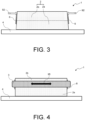
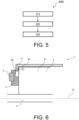
- Figures 2 to 4 illustrate a perspective view of a projection of a half of the rotor 1 during each of steps 310 to 330 of the rotor assembly method 300, according to an embodiment of the invention.
- Figure 5 is a flowchart of the steps 310 to 330 of the rotor assembly method 300 according to an embodiment of the invention.
- the assembly step 310 is configured to install the stack of laminations of the rotor body 2 on the rotor shaft 4, as illustrated in Figure 2 .
- the stack of laminations comprises an inner portion 2a and an outer portion 2b.
- the outer portion 2b is more distant to the rotor shaft 4.
- the compressed outer portion 2b comprises the teeth 21 projecting radially.
- the inner portion 2a presents a diameter substantially equal to a half of a diameter of the rotor body 2.
- the compression step 320 consists of compressing the outer portion 2b by an axial compression force 92 to form a compressed outer portion 2b, and accordingly, a slightly fan-out inner portion 2a. A distance between two axial ends of the inner portion 2a is thus greater than a distance between two axial ends of the compressed outer portion 2b, as illustrated in Figure 3 .
- the compression step 320 comprises applying the axial compression force 92 on the two axial ends of the outer portion 2b.
- the axial compression force 92 is applied, for example, by a pressing device (not illustrated in Figure 3 ) which is in contact with the two axial ends of the outer portion 2b.
- the pressing device is not in contact with the two axial ends of the inner portion 2a.
- the pressing device is preferably a clamping device 71, as illustrated in Figure 6 .
- FIG 6 illustrate one of the pockets 60 in which a pressing portion of the clamping device 71 is inserted so as to apply the axial compression force 92.
- each tooth of the teeth 21 corresponds to two end plates 6 located at the two axial sides of the tooth.
- Figure 6 only illustrates one of the two axial sides of the tooth, wherein only one of the pockets 60 is described.
- the pocket 60 is a cavity between the corresponding end plate 6 and an area of an outer portion of the corresponding tooth belonging to the outer portion 2b of the stack of laminations.
- the compression step 320 comprises, for each tooth of the teeth 21, inserting in each of the pockets 60 of the two end plates 6 a pressing portion of the clamping device 71, and using the clamping device 71 to apply the axial compression force 92 on the areas of the outer portions of the tooth belonging to the outer portion 2b of the stack of laminations.
- the winding assembly and fixation step 330 consisting of winding the field coil 3 on the compressed outer portion 2b, as illustrated in Figure 4 . More precisely, the field coil 3 is wound on each tooth of the teeth 21 of the compressed outer portion 2b.
- the winding assembly and fixation step 330 further comprises removing the axial compression force 92 after the field coil 3 is wound on the lamination package.
- the pressing device is removed after the field coil 3 is wound on the outer portion 2b of the lamination package.
- the removal of the axial compression force 92 leads that the inner portion 2a and the outer portion 2b tend to return to their original status where the compression step 320 has not been performed yet. Therefore, such a pretension resulting from the axial compression force 92 makes the field coil 3 be precisely and firmly wound on the outer portion 2b.
- a pretension 95 of the field coil 3 ensures that the field coil 3 is precisely and firmly wound on each tooth of the teeth 21 of the lamination package of the rotor body 2, as illustrated in Figure 4 .
- the rotor assembly method according to the invention allows thus to precisely and firmly wind a field coil around each tooth of the teeth of the lamination package.
- the risk of mispositioning the field coil on the rotor body occurred in the rotor assembly phase or during operation of the rotor, is significantly reduced or completely avoided.
Landscapes
- Engineering & Computer Science (AREA)
- Power Engineering (AREA)
- Manufacturing & Machinery (AREA)
- Mechanical Engineering (AREA)
- Iron Core Of Rotating Electric Machines (AREA)
- Manufacture Of Motors, Generators (AREA)
Abstract
Description
- The present invention belongs to the field of rotary electric machines configured to be on board of an automotive vehicle, such as an electric vehicle (EV) or a hybrid vehicle (HV).
- The present invention relates, in particular, to the field of electric excited rotors, also called wound rotors or slip ring rotors, integrated to rotary electric machines.
- As is known, an electric or a hybrid automotive vehicle presents an electric drive comprising a rotary electric machine which needs to be supplied with electric power, for instance by a high voltage power supply battery, to deliver a mechanical power in order to ensure the propulsion of the vehicle.
- In a general manner, the rotary electric machine comprises a stator, referring to a fixed part of the rotary electric machine, and a rotor, referring to a rotating part of the rotary electric machine. The rotor then comprises a rotor shaft configured to ensure the transmission of the mechanical power between the rotary electric machine and an exterior driven apparatus, notably the wheels of the vehicle.
- In particular, it is known to have the rotor electric excited. This type of rotors is commonly referred as wound rotors or slip ring rotors. Such a rotor comprises a rotor body formed of a stack of laminations having a plurality of teeth projecting radially, and a field coil wound around each tooth of the teeth. The field coil is then connected to an external power supply through slip rings. The slip rings correspond to electro-mechanical devices configured to allow the exchange of electric power between the field coil, which rotates with the rotor, and the external power supply, which is fixed.
- The rotary electric machine for the electric or hybrid vehicles, the rotor is designed to rotate at high speeds, which may affect the holding of the field coil due to centrifugal forces. If the field coil is not precisely and firmly wound on the teeth of the rotor body, a malfunction of the rotor may occur.
- In this context, the main objective of the present invention is to provide a rotor assembly method allowing to precisely and firmly wind the field coil around each tooth of the teeth of the rotor.
- The present invention concerns a rotor assembly method comprising an assembly step, a compression step and a winding assembly and fixation step. The assembly step is configured to install on a rotor shaft of a rotor, a lamination package formed of a stack of laminations, wherein the stack of laminations comprises an inner portion and an outer portion which is, compared to the inner portion, more distant to the rotor shaft. The compression step consists of compressing the outer portion by an axial compression force to form a compressed outer portion. The winding assembly and fixation step comprises winding a field coil on the compressed outer portion, and removing the axial compression force after the field coil is wound.
- Therefore, the rotor assembly method according to the present invention allows to precisely and firmly wind a field coil on a lamination package of the rotor body. Indeed, after a field coil is wound on the compressed outer portion, a pretension of the field coil is ensured and advantageously allows the field coil to be precisely and firmly wound on the lamination package of the rotor. The risk of mispositioning the field coil on the rotor body occurred in the rotor assembly phase or during operation of the rotor, is thus significantly reduced or completely avoided.
- According to an embodiment, the compression step comprises applying the axial compression force on two axial ends of the outer portion.
- Advantageously, the pressing device may not be in contact with two axial ends of the inner portion.
- The lamination package comprises teeth projecting radially. Thus, the pretension of the field coil ensures that the field coil is correctly wound on each of the tooth of the teeth.
- Preferably, the compression step comprises using a pressing device to apply the axial compression force; the pressing device being then removed after the winding assembly and fixation step.
- Especially, the assembly and fixation step comprises using a pretension resulting from the axial compression force so that the field coil is precisely and firmly wound on the outer portion.
- According to an embodiment, the rotor comprises end plates, and the end plates comprise each a pocket. Each of the pockets faces a tooth of the teeth of the stack of laminations, wherein the pocket is a cavity between the corresponding end plate and an area of an outer portion of the corresponding tooth belonging to the outer portion of the stack of laminations. Each tooth of the teeth corresponds to two end plates located at two axial sides of the tooth.
- Preferably, the pressing device is a clamping device. The compression step comprises, for each tooth of the teeth, inserting in each of the pockets of the two end plates a pressing portion of the clamping device, and using the clamping device to apply the axial compression force on the areas of the outer portions of the tooth.
- Furthermore, the present invention concerns a rotor being manufactured by using a rotor assembly method as mentioned above.
- Preferably, the rotor is an electric excited rotor for an electrically excited synchronous motor (EESM).
- According to an aspect of the invention, the invention relates to a rotary electric machine comprising the rotor as described previously and a stator.
- Another aspect of the invention is an electric drive, comprising the rotary electric machine and an inverter configured to convert a direct current voltage coming from a high-voltage power supply battery into an alternating current voltage so as to drive the rotary electric machine. The AC voltage may be a multiphase AC voltage, especially a three-phase voltage.
- A further aspect of the invention is an electric of a hybrid vehicle, comprising the electric drive for driving the vehicle. The vehicle may comprise the high-voltage power supply battery, preferably a rechargeable battery for providing the DC voltage to the inverter, if applicable.
- These and other objects, features, aspects and advantages of the present invention will become apparent to those skilled in the art from the following detailed description, which, taken in conjunction with the annexed drawings, discloses preferred embodiments of the present invention.
- The invention will be better understood on reading the description that follows, and by referring to the appended drawings given as non-limiting examples, in which identical references are given to similar objects and in which:
-
Figure 1 illustrates a partial view of an example of a rotor according to an embodiment of the invention; -
Figures 2 to 4 illustrate a perspective view of a projection of a half of the rotor during each of steps of a rotor assembly method according to an embodiment of the invention; -
Figure 5 is a flowchart of the steps of the rotor assembly method according to an embodiment of the invention; -
Figure 6 illustrates using a clamping device to apply an axial compression force during a compression step of the rotor assembly method according to an embodiment of the invention; and -
Figure 7 is a schematic diagram of an automotive electric or hybrid vehicle comprising the rotor of a rotary electric machine according to an embodiment of the invention. - Several embodiments of the present invention will be detailed hereafter with reference to the drawings. It will be apparent to those skilled in the art from this present disclosure that the following description of these embodiments of the present invention are provided for illustration only and not for the purpose of limiting the invention as defined by the appended claims and their equivalents.
- In reference to
Figure 7 , an aspect of the invention is an electric vehicle or a hybrid electric automotive vehicle (EV) comprising wheels and an electric drive configured to drive at least indirectly at least one of the wheels of the vehicle. The vehicle may comprise a high-voltage power supply battery B, preferably a rechargeable battery, for providing electric power to the electric drive. However, the invention is not limited to this domain. - Another aspect of the invention is the electric drive comprising a rotary electric machine (i.e., an electric motor) M and an inverter I configured to convert a direct current (DC) voltage coming from the high-voltage power supply battery B into an alternating current (AC) voltage in order to drive the rotary electric machine M. The rotary electric machine M may in particular be a three-phase rotary electric machine supplied with a three-phase AC voltage.
- The invention also relates to the rotary electric machine comprising a stator, referring to a fixed part of the rotary electric machine, and a rotor, referring to a rotating part of the rotary electric machine. The
rotor 1 is, preferably, an electric excited rotor, also commonly referred as a wound rotor or a slip ring rotor for an electrically excited synchronous motor (EESM). More precisely, the stator presents a cylinder shape and surrounds coaxially therotor 1. Then, the rotary electric machine comprises a casing covering both the stator and therotor 1. Ordinarily, the stator comprises a stator body formed of a stack of stator laminations having a plurality of stator teeth projecting radially, and stator windings wound around the stator teeth. -
Figure 1 illustrates a partial view of an example of therotor 1 according to a further aspect of the invention. Therotor 1 presents a shape of a cylinder and comprises arotor shaft 4 configured to rotate around arotation axis 1X, arotor body 2 comprising a lamination package formed of a stack of laminations having a plurality ofteeth 21 projecting radially, and at least onefield coil 3 wound around each tooth of theteeth 21. Arotor assembly method 300 allowing to precisely and firmly wind thefield coil 3 on the rotor body 2 (or more precisely, on theteeth 21 of the rotor 1), will be described in detail in the following paragraphs. - The laminations of the
rotor body 2 are especially stacked along therotation axis 1X. The invention is not limited to the number ofteeth 21. Theteeth 21 may notably comprise four, six, or eight teeth for example. Therotor body 2 is configured to be mounted coaxially on therotor shaft 4, For instance, therotor body 2 may be press-fitted on therotor shaft 4. Therotor body 2 is for example made of steel or silicone steel. - The
field coil 3 is then connected to an external power supply through at least one slip ring (not represented) mounted on therotor shaft 4, namely on an axial end of therotor shaft 4. Thefield coil 3 is preferably made of copper. The slip rings especially correspond to electro-mechanical devices configured to allow the exchange of electric power between a rotating element and a fixed element, here respectively thefield coil 3 and the external power supply. Therotor 1 may further comprise a holder such that the slip rings are mounted on therotor shaft 4 through the holder. - The
rotor 1 may further compriseend plates 6, as represented inFigure 1 , configured to come respectively against two axial ends of therotor body 2. Only one of the two axial ends of therotor body 2 is represented as "142" inFigure 1 . Theend plates 6 notably present an annular shape, substantially similar to the shape of the two axial ends of therotor body 2 such that to be able to cover the two axial ends. Then, thefield coil 3 advantageously passes over theend plates 6. In other words, theend plates 6 are located between therotor body 2 and the coil ends of thefield coil 3 such that to provide a mechanical holding of the stack of laminations and to electrically insulate axially thefield coil 3 from therotor body 2. - In the present embodiment, the
end plates 6 comprise each apocket 60 facing a tooth of theteeth 21 of the stack of laminations, as illustrated inFigures 1 and6 . Each tooth of theteeth 21 corresponds to twoend plates 6 located at two axial sides of the tooth. - The
rotor 1 further compriseswedge elements 110 extending axially and arranged in slots respectively located between two adjacent teeth of theteeth 21. Then, the slots are notably filled with a filling material, for instance a resin, so as to fixate thefield coil 3. Thefield coil 3 is thus prevented from moving due to centrifugal forces during in-service life of therotor 1. Therotor 1 advantageously comprises twoend caps 8 coming against two axial ends of therotor body 2. -
Figures 2 to 4 illustrate a perspective view of a projection of a half of therotor 1 during each ofsteps 310 to 330 of therotor assembly method 300, according to an embodiment of the invention.Figure 5 is a flowchart of thesteps 310 to 330 of therotor assembly method 300 according to an embodiment of the invention. - The
assembly step 310 is configured to install the stack of laminations of therotor body 2 on therotor shaft 4, as illustrated inFigure 2 . The stack of laminations comprises aninner portion 2a and anouter portion 2b. Compared to theinner portion 2a, theouter portion 2b is more distant to therotor shaft 4. The compressedouter portion 2b comprises theteeth 21 projecting radially. Preferably, theinner portion 2a presents a diameter substantially equal to a half of a diameter of therotor body 2. - The
compression step 320 consists of compressing theouter portion 2b by anaxial compression force 92 to form a compressedouter portion 2b, and accordingly, a slightly fan-outinner portion 2a. A distance between two axial ends of theinner portion 2a is thus greater than a distance between two axial ends of the compressedouter portion 2b, as illustrated inFigure 3 . - According to an embodiment, the
compression step 320 comprises applying theaxial compression force 92 on the two axial ends of theouter portion 2b. Theaxial compression force 92 is applied, for example, by a pressing device (not illustrated inFigure 3 ) which is in contact with the two axial ends of theouter portion 2b. The pressing device is not in contact with the two axial ends of theinner portion 2a. The pressing device is preferably aclamping device 71, as illustrated inFigure 6 . -
Figure 6 illustrate one of thepockets 60 in which a pressing portion of theclamping device 71 is inserted so as to apply theaxial compression force 92. As mentioned above, each tooth of theteeth 21 corresponds to twoend plates 6 located at the two axial sides of the tooth.Figure 6 only illustrates one of the two axial sides of the tooth, wherein only one of thepockets 60 is described. - The
pocket 60 is a cavity between thecorresponding end plate 6 and an area of an outer portion of the corresponding tooth belonging to theouter portion 2b of the stack of laminations. - According to an embodiment, the
compression step 320 comprises, for each tooth of theteeth 21, inserting in each of thepockets 60 of the two end plates 6 a pressing portion of theclamping device 71, and using theclamping device 71 to apply theaxial compression force 92 on the areas of the outer portions of the tooth belonging to theouter portion 2b of the stack of laminations. - The winding assembly and
fixation step 330, consisting of winding thefield coil 3 on the compressedouter portion 2b, as illustrated inFigure 4 . More precisely, thefield coil 3 is wound on each tooth of theteeth 21 of the compressedouter portion 2b. - The winding assembly and
fixation step 330 further comprises removing theaxial compression force 92 after thefield coil 3 is wound on the lamination package. For example, the pressing device is removed after thefield coil 3 is wound on theouter portion 2b of the lamination package. The removal of theaxial compression force 92 leads that theinner portion 2a and theouter portion 2b tend to return to their original status where thecompression step 320 has not been performed yet. Therefore, such a pretension resulting from theaxial compression force 92 makes thefield coil 3 be precisely and firmly wound on theouter portion 2b. - Then, after the
field coil 3 is wound and theaxial compression force 92 is removed, apretension 95 of thefield coil 3 ensures that thefield coil 3 is precisely and firmly wound on each tooth of theteeth 21 of the lamination package of therotor body 2, as illustrated inFigure 4 . - The rotor assembly method according to the invention allows thus to precisely and firmly wind a field coil around each tooth of the teeth of the lamination package. The risk of mispositioning the field coil on the rotor body occurred in the rotor assembly phase or during operation of the rotor, is significantly reduced or completely avoided.
- Although embodiments have been described with reference to a number of illustrative embodiments thereof, it should be understood that numerous other modifications and embodiments can be devised by those skilled in the art that will fall within the spirit and scope of the principles of this disclosure.
Claims (6)
- A rotor assembly method (300), comprising:- an assembly step (310) configured to install on a rotor shaft (4) of a rotor (1), a lamination package formed of a stack of laminations, wherein the stack of laminations comprises an inner portion (2a) and an outer portion (2b) which is, compared to the inner portion (2a), more distant to the rotor shaft (4);- a compression step (320) consisting of compressing the outer portion (2b) by an axial compression force (92) to form a compressed outer portion (2b); and- a winding assembly and fixation step (330) comprising winding a field coil (3) on the compressed outer portion (2b), and removing the axial compression force (92) after the field coil (3) is wound.
- The rotor assembly method (300) according to the preceding claim, wherein the compression step (320) comprises applying the axial compression force (92) on two axial ends of the outer portion (2b).
- The rotor assembly method (300) according to the preceding claim, wherein the compression step (320) comprises using a pressing device to apply the axial compression force (92); the pressing device being then removed after the winding assembly and fixation step (330).
- The rotor assembly method (300) according to the preceding claim, wherein:- the rotor (1) comprises end plates (6), and the end plates (6) comprise each a pocket (60); each of the pockets (60) facing a tooth of the teeth (21) of the stack of laminations, wherein the pocket (60) is a cavity between the corresponding end plate (6) and an area of an outer portion of the corresponding tooth belonging to the outer portion (2b) of the stack of laminations; each tooth of the teeth (21) corresponding to two end plates (6) located at two axial sides of the tooth;- the pressing device is a clamping device (71);- the compression step (320) comprises, for each tooth of the teeth (21), inserting in each of the pockets (60) of the two end plates (6) a pressing portion of the clamping device (71), and using the clamping device (71) to apply the axial compression force (92) on the areas of the outer portions of the tooth belonging to the outer portion (2b) of the stack of laminations.
- A rotor (1) being manufactured by using a rotor assembly method (300) according to any one of the preceding claims.
- The rotor (1) according to the preceding claim, being an electric excited rotor for an electrically excited synchronous motor (EESM).
Priority Applications (4)
| Application Number | Priority Date | Filing Date | Title |
|---|---|---|---|
| EP21217494.0A EP4203279B1 (en) | 2021-12-23 | 2021-12-23 | A rotor assembly method |
| US18/717,725 US20250055358A1 (en) | 2021-12-23 | 2022-12-22 | Interlocked lamination package for winding of eesm rotor by process |
| CN202280084900.1A CN118476145A (en) | 2021-12-23 | 2022-12-22 | Rotor assembling method |
| PCT/EP2022/087541 WO2023118465A1 (en) | 2021-12-23 | 2022-12-22 | A rotor assembly method |
Applications Claiming Priority (1)
| Application Number | Priority Date | Filing Date | Title |
|---|---|---|---|
| EP21217494.0A EP4203279B1 (en) | 2021-12-23 | 2021-12-23 | A rotor assembly method |
Publications (2)
| Publication Number | Publication Date |
|---|---|
| EP4203279A1 true EP4203279A1 (en) | 2023-06-28 |
| EP4203279B1 EP4203279B1 (en) | 2024-07-10 |
Family
ID=79164556
Family Applications (1)
| Application Number | Title | Priority Date | Filing Date |
|---|---|---|---|
| EP21217494.0A Active EP4203279B1 (en) | 2021-12-23 | 2021-12-23 | A rotor assembly method |
Country Status (4)
| Country | Link |
|---|---|
| US (1) | US20250055358A1 (en) |
| EP (1) | EP4203279B1 (en) |
| CN (1) | CN118476145A (en) |
| WO (1) | WO2023118465A1 (en) |
Families Citing this family (1)
| Publication number | Priority date | Publication date | Assignee | Title |
|---|---|---|---|---|
| FR3153201A1 (en) * | 2023-09-18 | 2025-03-21 | Renault S.A.S. | Method of winding a rotor pole of an electric machine and compression tool |
Citations (5)
| Publication number | Priority date | Publication date | Assignee | Title |
|---|---|---|---|---|
| US3882336A (en) * | 1973-12-03 | 1975-05-06 | Briggs & Stratton Corp | Electric motor armature core |
| EP0957561A2 (en) * | 1998-04-14 | 1999-11-17 | Alstom UK Limited | Rotor cores for electrical rotating machines |
| US20120080973A1 (en) * | 2010-10-04 | 2012-04-05 | Asmo Co., Ltd. | Armature for rotary electric apparatus and manufacturing method for the same |
| JP5030714B2 (en) * | 2007-09-07 | 2012-09-19 | 東芝キヤリア株式会社 | Winding method and winding apparatus for concentrated winding stator |
| US20200204022A1 (en) * | 2018-12-20 | 2020-06-25 | Teco-Westinghouse Motor Company | High Speed Induction Machine |
-
2021
- 2021-12-23 EP EP21217494.0A patent/EP4203279B1/en active Active
-
2022
- 2022-12-22 WO PCT/EP2022/087541 patent/WO2023118465A1/en not_active Ceased
- 2022-12-22 US US18/717,725 patent/US20250055358A1/en active Pending
- 2022-12-22 CN CN202280084900.1A patent/CN118476145A/en active Pending
Patent Citations (5)
| Publication number | Priority date | Publication date | Assignee | Title |
|---|---|---|---|---|
| US3882336A (en) * | 1973-12-03 | 1975-05-06 | Briggs & Stratton Corp | Electric motor armature core |
| EP0957561A2 (en) * | 1998-04-14 | 1999-11-17 | Alstom UK Limited | Rotor cores for electrical rotating machines |
| JP5030714B2 (en) * | 2007-09-07 | 2012-09-19 | 東芝キヤリア株式会社 | Winding method and winding apparatus for concentrated winding stator |
| US20120080973A1 (en) * | 2010-10-04 | 2012-04-05 | Asmo Co., Ltd. | Armature for rotary electric apparatus and manufacturing method for the same |
| US20200204022A1 (en) * | 2018-12-20 | 2020-06-25 | Teco-Westinghouse Motor Company | High Speed Induction Machine |
Also Published As
| Publication number | Publication date |
|---|---|
| EP4203279B1 (en) | 2024-07-10 |
| US20250055358A1 (en) | 2025-02-13 |
| CN118476145A (en) | 2024-08-09 |
| WO2023118465A1 (en) | 2023-06-29 |
Similar Documents
| Publication | Publication Date | Title |
|---|---|---|
| US12374945B2 (en) | Rotor for an electric machine having a radial cooling duct in the laminated core | |
| US12308720B2 (en) | Wedge element for an electric excited rotor | |
| US12388306B2 (en) | Rotor for a rotary electric machine having a barrier protecting coil ends of the rotor | |
| US20140175935A1 (en) | Rotary electric machine | |
| US20220131429A1 (en) | Rotor for an electrical machine, electrical machine for a vehicle, and method for manufacturing a rotor for an electrical machine | |
| KR20230096884A (en) | Electric excited rotor having an insulation paper and method for producing the same | |
| US20250055358A1 (en) | Interlocked lamination package for winding of eesm rotor by process | |
| US20250015682A1 (en) | A rotor assembly method | |
| US20230208088A1 (en) | Electrical connector for a separately excited rotor | |
| EP4203276A1 (en) | Electrical connector for a separately excited rotor | |
| JP5401225B2 (en) | Rotating electric machine | |
| WO2023118469A1 (en) | Guided wedge element for an electric excited rotor | |
| EP4203267A1 (en) | Overmolded separately excited rotor | |
| EP4224682A1 (en) | Electrical connecting assembly for a separately excited rotor | |
| EP4199310A1 (en) | A rotor for a rotary electric machine | |
| EP4203275A1 (en) | Electrical connector for a separately excited rotor | |
| US20230208226A1 (en) | Welding of a stack of laminations for a rotor | |
| JP2008271714A (en) | Manufacturing method of rotating electrical machine | |
| WO2014185134A1 (en) | Stator for rotational electric machine | |
| WO2023144384A1 (en) | Integrated insulation element and wedge elements for an electric excited rotor | |
| EP4203259A1 (en) | A rotor for a rotary electric machine | |
| EP4199315A1 (en) | A rotor for a rotary electric machine | |
| EP4203265A1 (en) | A rotor for a rotary electric machine | |
| EP4203249A1 (en) | Electrical insulation for a separately excited rotor | |
| CN117223193A (en) | Components with cylindrical laminated core stacks for electric machines |
Legal Events
| Date | Code | Title | Description |
|---|---|---|---|
| PUAI | Public reference made under article 153(3) epc to a published international application that has entered the european phase |
Free format text: ORIGINAL CODE: 0009012 |
|
| STAA | Information on the status of an ep patent application or granted ep patent |
Free format text: STATUS: THE APPLICATION HAS BEEN PUBLISHED |
|
| AK | Designated contracting states |
Kind code of ref document: A1 Designated state(s): AL AT BE BG CH CY CZ DE DK EE ES FI FR GB GR HR HU IE IS IT LI LT LU LV MC MK MT NL NO PL PT RO RS SE SI SK SM TR |
|
| STAA | Information on the status of an ep patent application or granted ep patent |
Free format text: STATUS: REQUEST FOR EXAMINATION WAS MADE |
|
| 17P | Request for examination filed |
Effective date: 20231215 |
|
| RBV | Designated contracting states (corrected) |
Designated state(s): AL AT BE BG CH CY CZ DE DK EE ES FI FR GB GR HR HU IE IS IT LI LT LU LV MC MK MT NL NO PL PT RO RS SE SI SK SM TR |
|
| GRAP | Despatch of communication of intention to grant a patent |
Free format text: ORIGINAL CODE: EPIDOSNIGR1 |
|
| STAA | Information on the status of an ep patent application or granted ep patent |
Free format text: STATUS: GRANT OF PATENT IS INTENDED |
|
| INTG | Intention to grant announced |
Effective date: 20240202 |
|
| GRAS | Grant fee paid |
Free format text: ORIGINAL CODE: EPIDOSNIGR3 |
|
| GRAA | (expected) grant |
Free format text: ORIGINAL CODE: 0009210 |
|
| STAA | Information on the status of an ep patent application or granted ep patent |
Free format text: STATUS: THE PATENT HAS BEEN GRANTED |
|
| AK | Designated contracting states |
Kind code of ref document: B1 Designated state(s): AL AT BE BG CH CY CZ DE DK EE ES FI FR GB GR HR HU IE IS IT LI LT LU LV MC MK MT NL NO PL PT RO RS SE SI SK SM TR |
|
| REG | Reference to a national code |
Ref country code: CH Ref legal event code: EP |
|
| REG | Reference to a national code |
Ref country code: DE Ref legal event code: R096 Ref document number: 602021015434 Country of ref document: DE |
|
| REG | Reference to a national code |
Ref country code: LT Ref legal event code: MG9D |
|
| REG | Reference to a national code |
Ref country code: NL Ref legal event code: MP Effective date: 20240710 |
|
| P01 | Opt-out of the competence of the unified patent court (upc) registered |
Free format text: CASE NUMBER: APP_56570/2024 Effective date: 20241016 |
|
| PG25 | Lapsed in a contracting state [announced via postgrant information from national office to epo] |
Ref country code: PT Free format text: LAPSE BECAUSE OF FAILURE TO SUBMIT A TRANSLATION OF THE DESCRIPTION OR TO PAY THE FEE WITHIN THE PRESCRIBED TIME-LIMIT Effective date: 20241111 |
|
| REG | Reference to a national code |
Ref country code: AT Ref legal event code: MK05 Ref document number: 1702918 Country of ref document: AT Kind code of ref document: T Effective date: 20240710 |
|
| PG25 | Lapsed in a contracting state [announced via postgrant information from national office to epo] |
Ref country code: NL Free format text: LAPSE BECAUSE OF FAILURE TO SUBMIT A TRANSLATION OF THE DESCRIPTION OR TO PAY THE FEE WITHIN THE PRESCRIBED TIME-LIMIT Effective date: 20240710 |
|
| PG25 | Lapsed in a contracting state [announced via postgrant information from national office to epo] |
Ref country code: PT Free format text: LAPSE BECAUSE OF FAILURE TO SUBMIT A TRANSLATION OF THE DESCRIPTION OR TO PAY THE FEE WITHIN THE PRESCRIBED TIME-LIMIT Effective date: 20241111 Ref country code: NL Free format text: LAPSE BECAUSE OF FAILURE TO SUBMIT A TRANSLATION OF THE DESCRIPTION OR TO PAY THE FEE WITHIN THE PRESCRIBED TIME-LIMIT Effective date: 20240710 |
|
| PG25 | Lapsed in a contracting state [announced via postgrant information from national office to epo] |
Ref country code: NO Free format text: LAPSE BECAUSE OF FAILURE TO SUBMIT A TRANSLATION OF THE DESCRIPTION OR TO PAY THE FEE WITHIN THE PRESCRIBED TIME-LIMIT Effective date: 20241010 |
|
| PG25 | Lapsed in a contracting state [announced via postgrant information from national office to epo] |
Ref country code: FI Free format text: LAPSE BECAUSE OF FAILURE TO SUBMIT A TRANSLATION OF THE DESCRIPTION OR TO PAY THE FEE WITHIN THE PRESCRIBED TIME-LIMIT Effective date: 20240710 Ref country code: GR Free format text: LAPSE BECAUSE OF FAILURE TO SUBMIT A TRANSLATION OF THE DESCRIPTION OR TO PAY THE FEE WITHIN THE PRESCRIBED TIME-LIMIT Effective date: 20241011 Ref country code: PL Free format text: LAPSE BECAUSE OF FAILURE TO SUBMIT A TRANSLATION OF THE DESCRIPTION OR TO PAY THE FEE WITHIN THE PRESCRIBED TIME-LIMIT Effective date: 20240710 |
|
| PG25 | Lapsed in a contracting state [announced via postgrant information from national office to epo] |
Ref country code: BG Free format text: LAPSE BECAUSE OF FAILURE TO SUBMIT A TRANSLATION OF THE DESCRIPTION OR TO PAY THE FEE WITHIN THE PRESCRIBED TIME-LIMIT Effective date: 20240710 |
|
| PG25 | Lapsed in a contracting state [announced via postgrant information from national office to epo] |
Ref country code: LV Free format text: LAPSE BECAUSE OF FAILURE TO SUBMIT A TRANSLATION OF THE DESCRIPTION OR TO PAY THE FEE WITHIN THE PRESCRIBED TIME-LIMIT Effective date: 20240710 |
|
| PG25 | Lapsed in a contracting state [announced via postgrant information from national office to epo] |
Ref country code: IS Free format text: LAPSE BECAUSE OF FAILURE TO SUBMIT A TRANSLATION OF THE DESCRIPTION OR TO PAY THE FEE WITHIN THE PRESCRIBED TIME-LIMIT Effective date: 20241110 Ref country code: AT Free format text: LAPSE BECAUSE OF FAILURE TO SUBMIT A TRANSLATION OF THE DESCRIPTION OR TO PAY THE FEE WITHIN THE PRESCRIBED TIME-LIMIT Effective date: 20240710 |
|
| PG25 | Lapsed in a contracting state [announced via postgrant information from national office to epo] |
Ref country code: HR Free format text: LAPSE BECAUSE OF FAILURE TO SUBMIT A TRANSLATION OF THE DESCRIPTION OR TO PAY THE FEE WITHIN THE PRESCRIBED TIME-LIMIT Effective date: 20240710 |
|
| PG25 | Lapsed in a contracting state [announced via postgrant information from national office to epo] |
Ref country code: ES Free format text: LAPSE BECAUSE OF FAILURE TO SUBMIT A TRANSLATION OF THE DESCRIPTION OR TO PAY THE FEE WITHIN THE PRESCRIBED TIME-LIMIT Effective date: 20240710 Ref country code: RS Free format text: LAPSE BECAUSE OF FAILURE TO SUBMIT A TRANSLATION OF THE DESCRIPTION OR TO PAY THE FEE WITHIN THE PRESCRIBED TIME-LIMIT Effective date: 20241010 |
|
| PG25 | Lapsed in a contracting state [announced via postgrant information from national office to epo] |
Ref country code: RS Free format text: LAPSE BECAUSE OF FAILURE TO SUBMIT A TRANSLATION OF THE DESCRIPTION OR TO PAY THE FEE WITHIN THE PRESCRIBED TIME-LIMIT Effective date: 20241010 Ref country code: PL Free format text: LAPSE BECAUSE OF FAILURE TO SUBMIT A TRANSLATION OF THE DESCRIPTION OR TO PAY THE FEE WITHIN THE PRESCRIBED TIME-LIMIT Effective date: 20240710 Ref country code: NO Free format text: LAPSE BECAUSE OF FAILURE TO SUBMIT A TRANSLATION OF THE DESCRIPTION OR TO PAY THE FEE WITHIN THE PRESCRIBED TIME-LIMIT Effective date: 20241010 Ref country code: LV Free format text: LAPSE BECAUSE OF FAILURE TO SUBMIT A TRANSLATION OF THE DESCRIPTION OR TO PAY THE FEE WITHIN THE PRESCRIBED TIME-LIMIT Effective date: 20240710 Ref country code: IS Free format text: LAPSE BECAUSE OF FAILURE TO SUBMIT A TRANSLATION OF THE DESCRIPTION OR TO PAY THE FEE WITHIN THE PRESCRIBED TIME-LIMIT Effective date: 20241110 Ref country code: HR Free format text: LAPSE BECAUSE OF FAILURE TO SUBMIT A TRANSLATION OF THE DESCRIPTION OR TO PAY THE FEE WITHIN THE PRESCRIBED TIME-LIMIT Effective date: 20240710 Ref country code: GR Free format text: LAPSE BECAUSE OF FAILURE TO SUBMIT A TRANSLATION OF THE DESCRIPTION OR TO PAY THE FEE WITHIN THE PRESCRIBED TIME-LIMIT Effective date: 20241011 Ref country code: FI Free format text: LAPSE BECAUSE OF FAILURE TO SUBMIT A TRANSLATION OF THE DESCRIPTION OR TO PAY THE FEE WITHIN THE PRESCRIBED TIME-LIMIT Effective date: 20240710 Ref country code: ES Free format text: LAPSE BECAUSE OF FAILURE TO SUBMIT A TRANSLATION OF THE DESCRIPTION OR TO PAY THE FEE WITHIN THE PRESCRIBED TIME-LIMIT Effective date: 20240710 Ref country code: BG Free format text: LAPSE BECAUSE OF FAILURE TO SUBMIT A TRANSLATION OF THE DESCRIPTION OR TO PAY THE FEE WITHIN THE PRESCRIBED TIME-LIMIT Effective date: 20240710 Ref country code: AT Free format text: LAPSE BECAUSE OF FAILURE TO SUBMIT A TRANSLATION OF THE DESCRIPTION OR TO PAY THE FEE WITHIN THE PRESCRIBED TIME-LIMIT Effective date: 20240710 |
|
| REG | Reference to a national code |
Ref country code: DE Ref legal event code: R097 Ref document number: 602021015434 Country of ref document: DE |
|
| PG25 | Lapsed in a contracting state [announced via postgrant information from national office to epo] |
Ref country code: DK Free format text: LAPSE BECAUSE OF FAILURE TO SUBMIT A TRANSLATION OF THE DESCRIPTION OR TO PAY THE FEE WITHIN THE PRESCRIBED TIME-LIMIT Effective date: 20240710 Ref country code: RO Free format text: LAPSE BECAUSE OF FAILURE TO SUBMIT A TRANSLATION OF THE DESCRIPTION OR TO PAY THE FEE WITHIN THE PRESCRIBED TIME-LIMIT Effective date: 20240710 Ref country code: SM Free format text: LAPSE BECAUSE OF FAILURE TO SUBMIT A TRANSLATION OF THE DESCRIPTION OR TO PAY THE FEE WITHIN THE PRESCRIBED TIME-LIMIT Effective date: 20240710 |
|
| PG25 | Lapsed in a contracting state [announced via postgrant information from national office to epo] |
Ref country code: EE Free format text: LAPSE BECAUSE OF FAILURE TO SUBMIT A TRANSLATION OF THE DESCRIPTION OR TO PAY THE FEE WITHIN THE PRESCRIBED TIME-LIMIT Effective date: 20240710 |
|
| PG25 | Lapsed in a contracting state [announced via postgrant information from national office to epo] |
Ref country code: CZ Free format text: LAPSE BECAUSE OF FAILURE TO SUBMIT A TRANSLATION OF THE DESCRIPTION OR TO PAY THE FEE WITHIN THE PRESCRIBED TIME-LIMIT Effective date: 20240710 |
|
| PG25 | Lapsed in a contracting state [announced via postgrant information from national office to epo] |
Ref country code: SK Free format text: LAPSE BECAUSE OF FAILURE TO SUBMIT A TRANSLATION OF THE DESCRIPTION OR TO PAY THE FEE WITHIN THE PRESCRIBED TIME-LIMIT Effective date: 20240710 |
|
| PLBE | No opposition filed within time limit |
Free format text: ORIGINAL CODE: 0009261 |
|
| STAA | Information on the status of an ep patent application or granted ep patent |
Free format text: STATUS: NO OPPOSITION FILED WITHIN TIME LIMIT |
|
| 26N | No opposition filed |
Effective date: 20250411 |
|
| PG25 | Lapsed in a contracting state [announced via postgrant information from national office to epo] |
Ref country code: MC Free format text: LAPSE BECAUSE OF FAILURE TO SUBMIT A TRANSLATION OF THE DESCRIPTION OR TO PAY THE FEE WITHIN THE PRESCRIBED TIME-LIMIT Effective date: 20240710 |
|
| REG | Reference to a national code |
Ref country code: CH Ref legal event code: PL |
|
| PG25 | Lapsed in a contracting state [announced via postgrant information from national office to epo] |
Ref country code: LU Free format text: LAPSE BECAUSE OF NON-PAYMENT OF DUE FEES Effective date: 20241223 |
|
| PG25 | Lapsed in a contracting state [announced via postgrant information from national office to epo] |
Ref country code: SE Free format text: LAPSE BECAUSE OF FAILURE TO SUBMIT A TRANSLATION OF THE DESCRIPTION OR TO PAY THE FEE WITHIN THE PRESCRIBED TIME-LIMIT Effective date: 20240710 |
|
| REG | Reference to a national code |
Ref country code: BE Ref legal event code: MM Effective date: 20241231 |
|
| PG25 | Lapsed in a contracting state [announced via postgrant information from national office to epo] |
Ref country code: BE Free format text: LAPSE BECAUSE OF NON-PAYMENT OF DUE FEES Effective date: 20241231 |
|
| PG25 | Lapsed in a contracting state [announced via postgrant information from national office to epo] |
Ref country code: CH Free format text: LAPSE BECAUSE OF NON-PAYMENT OF DUE FEES Effective date: 20241231 |
|
| PG25 | Lapsed in a contracting state [announced via postgrant information from national office to epo] |
Ref country code: IE Free format text: LAPSE BECAUSE OF NON-PAYMENT OF DUE FEES Effective date: 20241223 |
|
| PGFP | Annual fee paid to national office [announced via postgrant information from national office to epo] |
Ref country code: IT Payment date: 20251210 Year of fee payment: 5 |
|
| PGFP | Annual fee paid to national office [announced via postgrant information from national office to epo] |
Ref country code: FR Payment date: 20251230 Year of fee payment: 5 |
|
| PGFP | Annual fee paid to national office [announced via postgrant information from national office to epo] |
Ref country code: DE Payment date: 20251231 Year of fee payment: 5 |