EP4203255B1 - Motor with bidirectional terminals - Google Patents
Motor with bidirectional terminals Download PDFInfo
- Publication number
- EP4203255B1 EP4203255B1 EP22207516.0A EP22207516A EP4203255B1 EP 4203255 B1 EP4203255 B1 EP 4203255B1 EP 22207516 A EP22207516 A EP 22207516A EP 4203255 B1 EP4203255 B1 EP 4203255B1
- Authority
- EP
- European Patent Office
- Prior art keywords
- brush
- assembly
- terminals
- terminal
- motor
- Prior art date
- Legal status (The legal status is an assumption and is not a legal conclusion. Google has not performed a legal analysis and makes no representation as to the accuracy of the status listed.)
- Active
Links
Images


Classifications
-
- H—ELECTRICITY
- H02—GENERATION; CONVERSION OR DISTRIBUTION OF ELECTRIC POWER
- H02K—DYNAMO-ELECTRIC MACHINES
- H02K5/00—Casings; Enclosures; Supports
- H02K5/04—Casings or enclosures characterised by the shape, form or construction thereof
- H02K5/14—Means for supporting or protecting brushes or brush holders
- H02K5/143—Means for supporting or protecting brushes or brush holders for cooperation with commutators
-
- H—ELECTRICITY
- H02—GENERATION; CONVERSION OR DISTRIBUTION OF ELECTRIC POWER
- H02K—DYNAMO-ELECTRIC MACHINES
- H02K27/00—AC commutator motors or generators having mechanical commutator
- H02K27/22—AC commutator motors or generators having mechanical commutator having means for improving commutation, e.g. auxiliary fields, double windings, double brushes
-
- H—ELECTRICITY
- H01—ELECTRIC ELEMENTS
- H01R—ELECTRICALLY-CONDUCTIVE CONNECTIONS; STRUCTURAL ASSOCIATIONS OF A PLURALITY OF MUTUALLY-INSULATED ELECTRICAL CONNECTING ELEMENTS; COUPLING DEVICES; CURRENT COLLECTORS
- H01R39/00—Rotary current collectors, distributors or interrupters
- H01R39/02—Details for dynamo electric machines
- H01R39/18—Contacts for co-operation with commutator or slip-ring, e.g. contact brush
- H01R39/26—Solid sliding contacts, e.g. carbon brush
-
- H—ELECTRICITY
- H02—GENERATION; CONVERSION OR DISTRIBUTION OF ELECTRIC POWER
- H02K—DYNAMO-ELECTRIC MACHINES
- H02K1/00—Details of the magnetic circuit
- H02K1/06—Details of the magnetic circuit characterised by the shape, form or construction
- H02K1/22—Rotating parts of the magnetic circuit
-
- H—ELECTRICITY
- H02—GENERATION; CONVERSION OR DISTRIBUTION OF ELECTRIC POWER
- H02K—DYNAMO-ELECTRIC MACHINES
- H02K13/00—Structural associations of current collectors with motors or generators, e.g. brush mounting plates or connections to windings; Disposition of current collectors in motors or generators; Arrangements for improving commutation
- H02K13/006—Structural associations of commutators
-
- H—ELECTRICITY
- H02—GENERATION; CONVERSION OR DISTRIBUTION OF ELECTRIC POWER
- H02K—DYNAMO-ELECTRIC MACHINES
- H02K13/00—Structural associations of current collectors with motors or generators, e.g. brush mounting plates or connections to windings; Disposition of current collectors in motors or generators; Arrangements for improving commutation
- H02K13/10—Arrangements of brushes or commutators specially adapted for improving commutation
-
- H—ELECTRICITY
- H02—GENERATION; CONVERSION OR DISTRIBUTION OF ELECTRIC POWER
- H02K—DYNAMO-ELECTRIC MACHINES
- H02K5/00—Casings; Enclosures; Supports
- H02K5/04—Casings or enclosures characterised by the shape, form or construction thereof
- H02K5/14—Means for supporting or protecting brushes or brush holders
- H02K5/143—Means for supporting or protecting brushes or brush holders for cooperation with commutators
- H02K5/145—Fixedly supported brushes or brush holders, e.g. leaf or leaf-mounted brushes
-
- H—ELECTRICITY
- H02—GENERATION; CONVERSION OR DISTRIBUTION OF ELECTRIC POWER
- H02K—DYNAMO-ELECTRIC MACHINES
- H02K5/00—Casings; Enclosures; Supports
- H02K5/04—Casings or enclosures characterised by the shape, form or construction thereof
- H02K5/14—Means for supporting or protecting brushes or brush holders
- H02K5/143—Means for supporting or protecting brushes or brush holders for cooperation with commutators
- H02K5/148—Slidably supported brushes
-
- H—ELECTRICITY
- H02—GENERATION; CONVERSION OR DISTRIBUTION OF ELECTRIC POWER
- H02K—DYNAMO-ELECTRIC MACHINES
- H02K5/00—Casings; Enclosures; Supports
- H02K5/04—Casings or enclosures characterised by the shape, form or construction thereof
- H02K5/22—Auxiliary parts of casings not covered by groups H02K5/06-H02K5/20, e.g. shaped to form connection boxes or terminal boxes
- H02K5/225—Terminal boxes or connection arrangements
-
- H—ELECTRICITY
- H02—GENERATION; CONVERSION OR DISTRIBUTION OF ELECTRIC POWER
- H02K—DYNAMO-ELECTRIC MACHINES
- H02K2213/00—Specific aspects, not otherwise provided for and not covered by codes H02K2201/00 - H02K2211/00
- H02K2213/06—Machines characterised by the presence of fail safe, back up, redundant or other similar emergency arrangements
Definitions
- the present disclosure relates to a motor with bidirectional terminals capable of preventing assembly defects of a motor due to incorrect assembly of a brush terminal by installing the brush terminals on both the upper left and right sides of a brush card assembly.
- a motor converts electrical energy into mechanical energy
- components may be largely divided into a rotor and a stator.
- the stator is fixed, and the rotor rotates relative to the stator.
- the rotor is configured to interact electromagnetically with the stator.
- the motor is rotated by a force acting between the magnetic field generated by the stator and rotor and the current flowing in the coil.
- the motor may be divided into a brush motor and a brushless motor (BLDC motor).
- BLDC motor brushless motor
- brush motors are widely used in various industrial environments because they are relatively inexpensive compared to brushless motors.
- a brush card assembly transfers external power to a coil surrounding the internal rotor.
- a terminal for receiving external power, a choke coil, a brush holder, and a brush are installed in the brush card assembly.
- the brush is in contact with a commutator installed on a drive shaft of the motor, and the brush is elastically supported by a spring to be in close contact with the commutator.
- the terminal installed on the brush card assembly is arranged in one direction, and a pair of terminals consisting of (+) and (-) poles is designed to be disposed only on either the left or right side of the brush card assembly.
- a motor including a conventional terminal is disclosed in Korean Patent Registration Publication No. 10-2101713 .
- JP 2018 152938 A discloses a DC motor with brush card assembly. Only one pair of terminals protrudes from the upper surface. Each terminal is connected to a choke coil.
- US 5 717 271 A discloses a brush card assembly with two pairs of terminals. The terminals are shifted to the side. No choke coils are present.
- the terminal in the process of assembling the brush card assembly by the operator, the terminal is designed to be placed on the left (LH) side of the brush card, but the assembly direction of the motor is confused and assembled in the right (RH) direction, which often causes assembly defects that the terminal may not be connected to the main power source.
- the purpose of the present disclosure is to solve the problems of the prior art as described above, and to provide a motor with bidirectional terminals capable of preventing assembly failure of the motor due to erroneous assembly of a brush terminal by installing brush terminals on both the left and right sides of the upper surface of the brush card assembly.
- a motor with bidirectional terminals comprises: a yoke assembly forming a magnetic field; an armature assembly comprising a coil wound around a core slot formed in a core, disposed inside the yoke assembly and rotating around a rotation shaft; a brush card assembly fixed to one side of the yoke assembly and having a brush installed therein to supply power to a commutator installed in the armature assembly; and a brush terminal installed to protrude from the upper surface of the brush card assembly and connected to a power supply terminal to supply power to the brush card assembly.
- a plurality of the brush terminals are installed on the upper surface of the brush card assembly.
- the brush terminals are installed on the left and right sides of the upper surface of the brush card assembly, respectively.
- the brush terminal consists of a pair of terminals having a (+) pole and a (-) pole.
- the brush card assembly includes: a brush card housing with an installation space therein; a brush holder installed in the brush card housing and having a brush mounted therein; a choke coil installed on one side of the brush holder and supplying power to the brush; and a lead wire made of a steel wire and electrically connecting the brush terminal and the choke coil.
- the lead wire includes: a (+) pole lead wire connected to the (+) pole terminal on the left and the (+) pole terminal on the right, respectively, and connected to the choke coil; and a (-) pole lead wire connected to the (-) pole terminal on the left and the (+) pole terminal on the right, respectively, and connected to the choke coil.
- a motor with bidirectional terminals according to the present disclosure may have the following effects.
- FIG 1 is a perspective view showing the configuration of a preferred embodiment of the motor with bidirectional terminals according to the present disclosure
- FIG. 2 is a cross-sectional view showing the configuration of the preferred embodiment of the motor with bidirectional terminals according to the present disclosure
- FIG. 3 is an exploded view illustrating the configuration of the preferred embodiment of the motor with bidirectional terminals according to the present disclosure
- FIG. 4 is a perspective view illustrating a configuration of a brush card assembly constituting the embodiment of the present disclosure
- FIG. 5 is a plan view showing the configuration of the brush card assembly constituting the embodiment of the present disclosure
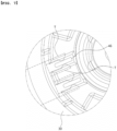
- FIG. 6 is a bottom view illustrating a configuration of the brush card assembly constituting the embodiment of the present disclosure
- FIG. 7 is an enlarged view illustrating a state in which the brush terminal constituting the embodiment of the present disclosure is connected to a power supply terminal.
- the motor with bidirectional terminals of the present disclosure comprises: a yoke assembly 10 forming a magnetic field; an armature assembly 20 comprising a coil wound around a core slot formed in a core 24, disposed inside the yoke assembly 10 and rotating around a rotation shaft 22; a brush card assembly 30 fixed to one side of the yoke assembly 10 and having a brush 40 installed therein to supply power to a commutator 26 installed in the armature assembly 20; and a brush terminal 44 installed to protrude from the upper surface of the brush card assembly 30 and connected to a power supply terminal to supply power to the brush card assembly 30.
- the present disclosure is characterized in that a plurality of the brush terminals 44 are installed on the upper surface of the brush card assembly 30.
- the yoke assembly 10 and the armature assembly 20 rotate relative to each other, and more precisely, the armature assembly 20 accommodated inside the fixed yoke assembly 10 rotates with respect to the yoke assembly 10. To this end, the armature assembly 20 converts power from electrical energy to rotational energy.
- the yoke 12 having a cylindrical shape or a rectangular parallelepiped shape forms an external frame of the yoke assembly 10.
- the yoke 12 is inserted into a separate motor housing (not shown), and a gear assembly or the like may be coupled to one side of the motor housing.
- the fixing magnet 16 provides a magnetic force for rotating the armature assembly 20 to be described later.
- the yoke assembly 10 forms a magnetic field.
- a plurality of fixing magnets 16 are provided along the inner surface of the rotation space 14, and are installed to be spaced apart therebetween.
- the armature assembly 20 is installed inside the yoke assembly 10.
- the armature assembly 20 receives power from the outside and converts the electrical energy into rotational energy, by which the armature assembly 20 may relatively rotate with respect to the yoke 12.
- the rotation shaft 22 rotates together at the center thereof, and the rotational force may be transmitted to a gear assembly (not shown). Since the rotation shaft 22 is coupled along the center of the armature assembly 20, the rotation shaft 22 may be viewed as a rotation center.
- a core armature 24 is formed in the frame of the assembly 20, which may be seen as a substantially cylindrical shape surrounding the rotation shaft 22 at the center.
- the core 24 is configured by stacking a plurality of core plates.
- the core plate is made of a thin metal steel plate, and when the core plates having the same shape are stacked, the core plates may have a three-dimensional shape as shown in FIG. 3 .
- a coil (enameled copper wire, not shown) is wound around the core 24.
- the coil constitutes the armature assembly 20 as the coil is repeatedly wound around the core slot (not shown) radially extending from the core 24.
- the brush card assembly 30 is installed on the upper portion of the yoke 12.
- the brush card assembly 30 receives power and signals from the outside and transmits them to the armature assembly 20, and the external power and signals are transmitted through a power supply terminal T to be described later.
- the brush card assembly 30 is connected to the commutator 26 of the motor to supply power to the commutator, and the commutator 26 transmits the power to the coil to rotate the armature assembly 20.
- the brush card assembly 30 is largely composed of a brush card housing 32, a brush holder 38, a brush 40, a choke coil 42, a brush terminal 44, and a lead wire 50.
- the brush card housing 32 forms a frame of the brush card assembly 30.
- the brush card housing 32 has a substantially circular shape and is coupled to the upper portion of the yoke assembly 10.
- the commutator 26 of the armature assembly 20 may face the brush 40 to be described later.
- the brush holder 38 and the brush 40 are installed on the lower surface of the brush card housing 32.
- the brush 40 is installed inside the brush holder 38 and disposed toward the commutator 26.
- a choke coil 42 is installed on the lower surface of the brush card housing 32.
- the choke coil 42 is a general choke coil, and a detailed description thereof will be omitted.
- the choke coil 42 may be installed on one side of each brush holder 38 to supply power to the brush 40.
- a brush terminal 44 is installed on the upper surface of the brush card housing 32.
- the brush terminal 44 is made of a metal material and is formed of a rectangular plate.
- a wire connection groove 48 is formed in the center of the lower end of the brush terminal 44.
- a lead wire 50 which will be described later, is inserted into the wire connection groove 48.
- the brush terminal 44 includes a pair of terminals 46 having a (+) pole and a (-) pole.
- the brush terminals 44 are installed on the left and right sides of the brush card housing 32 such that upper ends protrude upward, respectively.
- the power supply terminal T is connected to the brush terminal 44 to supply power to the brush card assembly 30.
- the brush terminal 44 may be installed on the left and right sides, respectively, based on the central shaft of the brush card housing 32. As the brush terminals 44 are equally disposed on the left and right sides of the brush card housing 32, one of the two brush terminals 44 may be connected to the power supply terminal T during the assembly process of the motor.
- the brush terminals 44 are disposed on the left and right sides, equally, thereby preventing assembly defects of the motor due to misassembly of the brush terminal 44 and improving the assembly productivity of the motor.
- Lead wires 50 are installed on the lower surface of the brush card housing 32.
- the lead wires 50 include a (+) pole lead wire 52 and a (-) pole lead wire 54.
- the lead wire 50 is a general lead wire and a detailed description thereof will be omitted.
- the (+) pole lead wires 52 are connected to the wire connection grooves 48 of each the (+) pole terminal 46 disposed on the left and right sides of the brush card housing 32, and ends of the (+) pole lead wires 52 are connected to the choke coil 42.
- the (+) pole lead wire 52 is connected to the (+) pole terminals 46 to transfer the (+) electrode to the choke coil 42.
- the (-) pole lead wires 54 are respectively connected to the wire connection grooves 48 of each the (-) pole terminal 46 disposed on the left and right sides of the brush card housing 32, and ends of the (-) pole lead wires 54 are connected to the choke coil 42.
- the (-) pole lead wires 54 are connected to the (-) pole terminals 46 to transfer the (-) electrode to the choke coil 42.
- (+) pole lead wire 52 and the (-) pole lead wire 54 are simultaneously connected to the (+) and (-) poles terminals 46 disposed on the left and right sides of the brush card housing 32.
- the operator combines the armature assembly 20 inside the yoke assembly 10.
- the rotation shaft 22 of the armature assembly 20 is positioned at the center, and the brush card assembly 30 is coupled and fixed to the upper side of the yoke assembly 10.
- the rotation shaft 22 of the armature assembly 20 is installed through the center hole 34 of the brush card assembly 30, and the brush 40 is installed at a position adjacent to the commutator 26 of the armature assembly 20.
- the operator When the assembly of the brush card assembly 30 and the yoke assembly 10 are completed, the operator combines the motor with bidirectional terminals with a motor connection portion where the power supply terminal T is disposed.
- the power supply terminal T may be disposed on the left or right side of the motor according to the specifications of the motor. Since the brush terminals 44 are installed on both the left and right sides of the upper surface of the brush card assembly 30, the operator may electrically connect the power supply terminal (T) and the brush terminals 44 without having to check the arrangement position of the power supply terminal (T).
Landscapes
- Engineering & Computer Science (AREA)
- Power Engineering (AREA)
- Motor Or Generator Frames (AREA)
- Dc Machiner (AREA)
- Motor Or Generator Current Collectors (AREA)
Description
- 1. The present disclosure relates to a motor with bidirectional terminals capable of preventing assembly defects of a motor due to incorrect assembly of a brush terminal by installing the brush terminals on both the upper left and right sides of a brush card assembly.
- 2. In general, a motor converts electrical energy into mechanical energy, and components may be largely divided into a rotor and a stator. The stator is fixed, and the rotor rotates relative to the stator.
- 3. Here, the rotor is configured to interact electromagnetically with the stator. As a result, the motor is rotated by a force acting between the magnetic field generated by the stator and rotor and the current flowing in the coil.
- 4. In general, the motor may be divided into a brush motor and a brushless motor (BLDC motor). Among them, brush motors are widely used in various industrial environments because they are relatively inexpensive compared to brushless motors.
- 5. In a brush type permanent magnet motor, a brush card assembly transfers external power to a coil surrounding the internal rotor. To this end, a terminal for receiving external power, a choke coil, a brush holder, and a brush are installed in the brush card assembly. Here, the brush is in contact with a commutator installed on a drive shaft of the motor, and the brush is elastically supported by a spring to be in close contact with the commutator.
- 6. In the conventional motor as described above, the terminal installed on the brush card assembly is arranged in one direction, and a pair of terminals consisting of (+) and (-) poles is designed to be disposed only on either the left or right side of the brush card assembly.
- 7. A motor including a conventional terminal is disclosed in
Korean Patent Registration Publication No. 10-2101713 JP 2018 152938 A US 5 717 271 A discloses a brush card assembly with two pairs of terminals. The terminals are shifted to the side. No choke coils are present. - 8. As the conventional terminal is installed only on one of the left or right side of the brush card assembly, there is a problem that the terminal is frequently misassembled when an operator assembles several types of motors in the process of producing the motor.
- 9. That is, in the process of assembling the brush card assembly by the operator, the terminal is designed to be placed on the left (LH) side of the brush card, but the assembly direction of the motor is confused and assembled in the right (RH) direction, which often causes assembly defects that the terminal may not be connected to the main power source.
-
- 10. (Patent Document 1)
Korea Patent No.10-2101713 - (Patent Document 2)
JP 2018 152938 A - (Patent Document 3)
US 5 717 271 A . - 11. The purpose of the present disclosure is to solve the problems of the prior art as described above, and to provide a motor with bidirectional terminals capable of preventing assembly failure of the motor due to erroneous assembly of a brush terminal by installing brush terminals on both the left and right sides of the upper surface of the brush card assembly.
- 12. According to the features of the present disclosure to achieve the above objects, a motor with bidirectional terminals comprises: a yoke assembly forming a magnetic field; an armature assembly comprising a coil wound around a core slot formed in a core, disposed inside the yoke assembly and rotating around a rotation shaft; a brush card assembly fixed to one side of the yoke assembly and having a brush installed therein to supply power to a commutator installed in the armature assembly; and a brush terminal installed to protrude from the upper surface of the brush card assembly and connected to a power supply terminal to supply power to the brush card assembly. A plurality of the brush terminals are installed on the upper surface of the brush card assembly.
- 13. The brush terminals are installed on the left and right sides of the upper surface of the brush card assembly, respectively.
- 14. The brush terminal consists of a pair of terminals having a (+) pole and a (-) pole.
- 15. The brush card assembly includes: a brush card housing with an installation space therein; a brush holder installed in the brush card housing and having a brush mounted therein; a choke coil installed on one side of the brush holder and supplying power to the brush; and a lead wire made of a steel wire and electrically connecting the brush terminal and the choke coil.
- 16. The lead wire includes: a (+) pole lead wire connected to the (+) pole terminal on the left and the (+) pole terminal on the right, respectively, and connected to the choke coil; and a (-) pole lead wire connected to the (-) pole terminal on the left and the (+) pole terminal on the right, respectively, and connected to the choke coil.
- 17. A motor with bidirectional terminals according to the present disclosure may have the following effects.
- 18. In the present disclosure, as brush terminals are installed on both the left and right sides of the upper surface of a brush card assembly, it is possible to prevent assembly defects of the motor due to misassembly of the brush terminal by an operator in the process of assembling the motor, while increasing assembly productivity of the motor.
- 19. In addition, as multiple brush terminals are installed, mold production in accordance with the installation direction of the brush terminal may be minimized, and there is an advantage that motor parts may be shared.
-
- 20.
FIG. 1 is a perspective view illustrating a configuration of a preferred embodiment of a motor with bidirectional terminals according to the present disclosure. - 21.
FIG. 2 is a cross-sectional view illustrating a configuration of the preferred embodiment of the motor with bidirectional terminals according to the present disclosure. - 22.
FIG. 3 is an exploded view illustrating the configuration of the preferred embodiment of the motor with bidirectional terminals according to the present disclosure. - 23.
FIG. 4 is a perspective view illustrating a configuration of a brush card assembly constituting the embodiment of the present disclosure. - 24.
FIG. 5 is a plan view showing the configuration of the brush card assembly constituting the embodiment of the present disclosure. - 25.
FIG. 6 is a bottom view illustrating a configuration of the brush card assembly constituting the embodiment of the present disclosure. - 26.
FIG. 7 is an enlarged view illustrating a state in which the brush terminal constituting the embodiment of the present disclosure is connected to a power supply terminal. - 27. Hereinafter, a preferred embodiment of a motor with bidirectional terminals according to the present disclosure will be described in detail with reference to the accompanying drawings.
- 28.
FIG 1 is a perspective view showing the configuration of a preferred embodiment of the motor with bidirectional terminals according to the present disclosure,FIG. 2 is a cross-sectional view showing the configuration of the preferred embodiment of the motor with bidirectional terminals according to the present disclosure,FIG. 3 is an exploded view illustrating the configuration of the preferred embodiment of the motor with bidirectional terminals according to the present disclosure,FIG. 4 is a perspective view illustrating a configuration of a brush card assembly constituting the embodiment of the present disclosure,FIG. 5 is a plan view showing the configuration of the brush card assembly constituting the embodiment of the present disclosure,FIG. 6 is a bottom view illustrating a configuration of the brush card assembly constituting the embodiment of the present disclosure, andFIG. 7 is an enlarged view illustrating a state in which the brush terminal constituting the embodiment of the present disclosure is connected to a power supply terminal. - 29. As shown in these drawings, the motor with bidirectional terminals of the present disclosure comprises: a
yoke assembly 10 forming a magnetic field; an armature assembly 20 comprising a coil wound around a core slot formed in acore 24, disposed inside theyoke assembly 10 and rotating around arotation shaft 22; abrush card assembly 30 fixed to one side of theyoke assembly 10 and having abrush 40 installed therein to supply power to acommutator 26 installed in the armature assembly 20; and abrush terminal 44 installed to protrude from the upper surface of thebrush card assembly 30 and connected to a power supply terminal to supply power to thebrush card assembly 30. The present disclosure is characterized in that a plurality of thebrush terminals 44 are installed on the upper surface of thebrush card assembly 30. - 30. First, the yoke assembly and the armature assembly among the configurations of the present disclosure will be described in detail.
- 31. The
yoke assembly 10 and the armature assembly 20 rotate relative to each other, and more precisely, the armature assembly 20 accommodated inside the fixedyoke assembly 10 rotates with respect to theyoke assembly 10. To this end, the armature assembly 20 converts power from electrical energy to rotational energy. - 32. In the structure of the
yoke assembly 10, theyoke 12 having a cylindrical shape or a rectangular parallelepiped shape forms an external frame of theyoke assembly 10. Theyoke 12 is inserted into a separate motor housing (not shown), and a gear assembly or the like may be coupled to one side of the motor housing. - 33. There is a
rotation space 14 inside theyoke 12, and a fixing magnet 16 is installed on the inner circumferential surface of therotation space 14. The fixing magnet 16 provides a magnetic force for rotating the armature assembly 20 to be described later. - 34. That is, the
yoke assembly 10 forms a magnetic field. A plurality of fixing magnets 16 are provided along the inner surface of therotation space 14, and are installed to be spaced apart therebetween. - 35. The armature assembly 20 is installed inside the
yoke assembly 10. The armature assembly 20 receives power from the outside and converts the electrical energy into rotational energy, by which the armature assembly 20 may relatively rotate with respect to theyoke 12. When the armature assembly 20 is rotated, therotation shaft 22 rotates together at the center thereof, and the rotational force may be transmitted to a gear assembly (not shown). Since therotation shaft 22 is coupled along the center of the armature assembly 20, therotation shaft 22 may be viewed as a rotation center. Acore armature 24 is formed in the frame of the assembly 20, which may be seen as a substantially cylindrical shape surrounding therotation shaft 22 at the center. - 36. The
core 24 is configured by stacking a plurality of core plates. The core plate is made of a thin metal steel plate, and when the core plates having the same shape are stacked, the core plates may have a three-dimensional shape as shown inFIG. 3 . A coil (enameled copper wire, not shown) is wound around thecore 24. - 37. The coil constitutes the armature assembly 20 as the coil is repeatedly wound around the core slot (not shown) radially extending from the
core 24. - 38. The
brush card assembly 30 is installed on the upper portion of theyoke 12. Thebrush card assembly 30 receives power and signals from the outside and transmits them to the armature assembly 20, and the external power and signals are transmitted through a power supply terminal T to be described later. Thebrush card assembly 30 is connected to thecommutator 26 of the motor to supply power to the commutator, and thecommutator 26 transmits the power to the coil to rotate the armature assembly 20. - 39. The
brush card assembly 30 is largely composed of abrush card housing 32, abrush holder 38, abrush 40, achoke coil 42, abrush terminal 44, and a lead wire 50. - 40. The
brush card housing 32 forms a frame of thebrush card assembly 30. Thebrush card housing 32 has a substantially circular shape and is coupled to the upper portion of theyoke assembly 10. When thebrush card assembly 30 and theyoke assembly 10 are assembled, thecommutator 26 of the armature assembly 20 may face thebrush 40 to be described later. - 41. Inside the
brush card housing 32, there is anempty installation space 36, and in the center of theinstallation space 36, there is acenter hole 34 into which therotation shaft 22 is fitted. A plurality of parts may be installed in theinstallation space 36, and in this embodiment, two ormore brush holders 38 andbrush 40 are installed in theinstallation space 36. - 42. The
brush holder 38 and thebrush 40 are installed on the lower surface of thebrush card housing 32. Thebrush 40 is installed inside thebrush holder 38 and disposed toward thecommutator 26. - 43. A
choke coil 42 is installed on the lower surface of thebrush card housing 32. Thechoke coil 42 is a general choke coil, and a detailed description thereof will be omitted. Thechoke coil 42 may be installed on one side of eachbrush holder 38 to supply power to thebrush 40. - 44. A
brush terminal 44 is installed on the upper surface of thebrush card housing 32. Thebrush terminal 44 is made of a metal material and is formed of a rectangular plate. Awire connection groove 48 is formed in the center of the lower end of thebrush terminal 44. A lead wire 50, which will be described later, is inserted into thewire connection groove 48. - 45. The
brush terminal 44 includes a pair ofterminals 46 having a (+) pole and a (-) pole. Thebrush terminals 44 are installed on the left and right sides of thebrush card housing 32 such that upper ends protrude upward, respectively. As shown inFIG. 7 , the power supply terminal T is connected to thebrush terminal 44 to supply power to thebrush card assembly 30. - 46. The
brush terminal 44 may be installed on the left and right sides, respectively, based on the central shaft of thebrush card housing 32. As thebrush terminals 44 are equally disposed on the left and right sides of thebrush card housing 32, one of the twobrush terminals 44 may be connected to the power supply terminal T during the assembly process of the motor. - 47. That is, even if an operator confuses the assembly direction of the
brush terminal 44 in the process of assembling the motor, thebrush terminals 44 are disposed on the left and right sides, equally, thereby preventing assembly defects of the motor due to misassembly of thebrush terminal 44 and improving the assembly productivity of the motor. - 48. Lead wires 50 are installed on the lower surface of the
brush card housing 32. The lead wires 50 include a (+)pole lead wire 52 and a (-)pole lead wire 54. The lead wire 50 is a general lead wire and a detailed description thereof will be omitted. The (+)pole lead wires 52 are connected to thewire connection grooves 48 of each the (+)pole terminal 46 disposed on the left and right sides of thebrush card housing 32, and ends of the (+)pole lead wires 52 are connected to thechoke coil 42. The (+)pole lead wire 52 is connected to the (+)pole terminals 46 to transfer the (+) electrode to thechoke coil 42. - 49. The (-)
pole lead wires 54 are respectively connected to thewire connection grooves 48 of each the (-)pole terminal 46 disposed on the left and right sides of thebrush card housing 32, and ends of the (-)pole lead wires 54 are connected to thechoke coil 42. The (-)pole lead wires 54 are connected to the (-)pole terminals 46 to transfer the (-) electrode to thechoke coil 42. - 50. That is, the (+)
pole lead wire 52 and the (-)pole lead wire 54 are simultaneously connected to the (+) and (-)poles terminals 46 disposed on the left and right sides of thebrush card housing 32. - 51. Therefore, when the power supply terminal (T) is connected to any one of the
brush terminals 44 disposed on the left and right sides of thebrush card housing 32, power may be supplied to thechoke coil 42 - 52. Next, looking at the assembly process of the motor with bidirectional terminals according to the present disclosure, the operator combines the armature assembly 20 inside the
yoke assembly 10. In a state where the armature assembly 20 is coupled to theyoke assembly 10, therotation shaft 22 of the armature assembly 20 is positioned at the center, and thebrush card assembly 30 is coupled and fixed to the upper side of theyoke assembly 10. - 53. The
rotation shaft 22 of the armature assembly 20 is installed through thecenter hole 34 of thebrush card assembly 30, and thebrush 40 is installed at a position adjacent to thecommutator 26 of the armature assembly 20. - 54. When the assembly of the
brush card assembly 30 and theyoke assembly 10 are completed, the operator combines the motor with bidirectional terminals with a motor connection portion where the power supply terminal T is disposed. - 55. The power supply terminal T may be disposed on the left or right side of the motor according to the specifications of the motor. Since the
brush terminals 44 are installed on both the left and right sides of the upper surface of thebrush card assembly 30, the operator may electrically connect the power supply terminal (T) and thebrush terminals 44 without having to check the arrangement position of the power supply terminal (T). - 56. As described above, as the
brush terminals 44 are installed on both the left and right sides of the upper surface of thebrush card assembly 30, even if the operator confuses the assembly direction of thebrush terminals 44 in the process of assembling the motor, it is possible to prevent assembly defects of the motor due to erroneous assembly of thebrush terminals 44, and increase the assembly productivity of the motor. -
10 Yoke assembly 12 Yoke 14 rotation space 16 fixing magnet 20 amateur assembly 22 rotation shaft 26 commutator 30 brush card assembly 32 brush card housing 34 center hall 36 installation space 38 brush holder 40 brush 4242 choke coil 44 brush terminal 4646 terminal 50 lead wire
Claims (1)
- A motor with bidirectional terminals comprising:a yoke assembly (10) forming a magnetic field;an armature assembly (20) comprising a coil wound around a core slot formed in a core, disposed inside the yoke assembly (10) and rotating around a rotation shaft (22);a brush card assembly (30) fixed to one side of the yoke assembly (10) and having a brush (40) installed therein to supply power to a commutator (26) installed in the armature assembly (20) ; anda plurality of brush terminals (44),wherein a brush terminal (44) of the plurality of brush terminals (44) consists of a pair of terminals having a (+) pole and a (-) pole and is installed to protrude from the upper surface of the brush card assembly (30) and connected to a power supply terminal to supply power to the brush card assembly (30),wherein the plurality of the brush terminals (44) are installed on the upper surface of the brush card assembly (30),wherein the plurality of brush terminals (44) are equally disposed circumferentially on the left and right sides of the shaft on the brush card assembly (30), respectively,wherein the brush card assembly (30) includes,a brush card housing (32) with an installation space (36) therein;a brush holder (38) installed in the brush card housing (32) and having the brush (40) mounted therein;a choke coil (42) installed on one side of the brush holder (38) and supplying power to the brush (40); anda lead wire (50) made of a steel wire and electrically connecting the plurality of brush terminals (44) and the choke coil (42),wherein the lead wire (50) includes:a (+) pole lead wire (52) connected to the (+) pole terminal on the left and the (+) pole terminal on the right, respectively, and connected to the choke coil (42); anda (-) pole lead wire (54) connected to the (-) pole terminal on the left and the (+) pole terminal on the right, respectively, and connected to the choke coil (42).
Applications Claiming Priority (1)
| Application Number | Priority Date | Filing Date | Title |
|---|---|---|---|
| KR1020210187692A KR20230098446A (en) | 2021-12-24 | 2021-12-24 | Motors With Bidirectional Terminals |
Publications (2)
| Publication Number | Publication Date |
|---|---|
| EP4203255A1 EP4203255A1 (en) | 2023-06-28 |
| EP4203255B1 true EP4203255B1 (en) | 2024-08-14 |
Family
ID=84357997
Family Applications (1)
| Application Number | Title | Priority Date | Filing Date |
|---|---|---|---|
| EP22207516.0A Active EP4203255B1 (en) | 2021-12-24 | 2022-11-15 | Motor with bidirectional terminals |
Country Status (4)
| Country | Link |
|---|---|
| US (1) | US12289024B2 (en) |
| EP (1) | EP4203255B1 (en) |
| KR (1) | KR20230098446A (en) |
| CN (1) | CN116345804A (en) |
Families Citing this family (1)
| Publication number | Priority date | Publication date | Assignee | Title |
|---|---|---|---|---|
| EP4597801A1 (en) * | 2024-01-30 | 2025-08-06 | Hilti Aktiengesellschaft | Multi-terminal stator |
Family Cites Families (13)
| Publication number | Priority date | Publication date | Assignee | Title |
|---|---|---|---|---|
| JPH0418220A (en) * | 1990-04-26 | 1992-01-22 | Aputodeito:Kk | Containing bag for tab terminal for capacitor and device for feeding tab terminal for capacitor in containing bag in specified direction to subsequent process |
| JP2577947Y2 (en) * | 1993-03-18 | 1998-08-06 | 株式会社ミツバ | Terminal plate structure for brush holder stay of electric motor |
| US5717271A (en) * | 1995-01-27 | 1998-02-10 | Mitsuba Corporation | Brush holder device and method of molding same |
| JP2004288625A (en) * | 2003-03-06 | 2004-10-14 | Auto Network Gijutsu Kenkyusho:Kk | Automotive wires |
| KR100901304B1 (en) * | 2007-06-12 | 2009-06-09 | 동양기전 주식회사 | Power Supply of Automotive Fan Motor |
| JP2014099957A (en) * | 2012-11-13 | 2014-05-29 | Nissin Kogyo Co Ltd | Electric motor and manufacturing method of electric motor |
| KR101515585B1 (en) | 2013-08-26 | 2015-05-04 | 효성전기주식회사 | A brush card assembly for the motor |
| JP6193071B2 (en) * | 2013-09-27 | 2017-09-06 | マーレエレクトリックドライブズジャパン株式会社 | DC motor |
| US9762015B2 (en) | 2014-06-10 | 2017-09-12 | General Electric Company | Brush holder apparatus and system |
| JP6813886B2 (en) * | 2017-03-10 | 2021-01-13 | 株式会社 五十嵐電機製作所 | DC motor with brush and its manufacturing method |
| KR102101713B1 (en) | 2018-12-20 | 2020-04-20 | 계양전기 주식회사 | Brush fixing device for motor |
| JP2020145825A (en) * | 2019-03-05 | 2020-09-10 | 東京パーツ工業株式会社 | Brush holding structure and motor with the brush holding structure |
| CN110299637A (en) * | 2019-07-12 | 2019-10-01 | 无锡君磊科技有限公司 | Charge connector female end, charge connector male end and charging connection device assembly |
-
2021
- 2021-12-24 KR KR1020210187692A patent/KR20230098446A/en active Pending
-
2022
- 2022-11-15 EP EP22207516.0A patent/EP4203255B1/en active Active
- 2022-11-23 CN CN202211470753.XA patent/CN116345804A/en active Pending
- 2022-12-01 US US18/073,011 patent/US12289024B2/en active Active
Also Published As
| Publication number | Publication date |
|---|---|
| KR20230098446A (en) | 2023-07-04 |
| US20230208265A1 (en) | 2023-06-29 |
| EP4203255A1 (en) | 2023-06-28 |
| US12289024B2 (en) | 2025-04-29 |
| CN116345804A (en) | 2023-06-27 |
Similar Documents
| Publication | Publication Date | Title |
|---|---|---|
| US11336146B2 (en) | Motor | |
| JP4649951B2 (en) | Motor and armature manufacturing method | |
| JP6248433B2 (en) | motor | |
| US6903483B2 (en) | Motor | |
| CN104052200A (en) | Electric machines and related methods | |
| CN106104980A (en) | Electromagnetic structure of the motor | |
| JP2012222942A (en) | Electric motor | |
| KR20180054087A (en) | Vehicle fan-motor using one-body type stator | |
| EP4203255A1 (en) | Motor with bidirectional terminals | |
| US6617724B2 (en) | Non-circular, flat motor | |
| CN116848769A (en) | electric motor | |
| EP1432105B1 (en) | Coreless Motor | |
| KR100213571B1 (en) | Double rotor/single stator and coreless-type bldc motor using one-body type stator | |
| US10958140B2 (en) | Motor | |
| US11973388B2 (en) | Rotating electric machine, insulator, and assembly method therefor | |
| KR20040065521A (en) | Brushless dc motor having slotless stator | |
| US12362623B2 (en) | Cover and motor comprising same | |
| JP2003070203A (en) | Pump driving dc motor | |
| US4433259A (en) | Electric rotating machine | |
| CN111697779A (en) | Motor unit and method for manufacturing motor unit | |
| EP4535615A1 (en) | Electric motor, core block, and stator core | |
| JP2024119643A (en) | Stator, motor | |
| JP2025002711A (en) | Motor | |
| CN114884257A (en) | Motor | |
| JP2004312812A (en) | Electric motor and fuel pump using the same |
Legal Events
| Date | Code | Title | Description |
|---|---|---|---|
| PUAI | Public reference made under article 153(3) epc to a published international application that has entered the european phase |
Free format text: ORIGINAL CODE: 0009012 |
|
| STAA | Information on the status of an ep patent application or granted ep patent |
Free format text: STATUS: REQUEST FOR EXAMINATION WAS MADE |
|
| 17P | Request for examination filed |
Effective date: 20221115 |
|
| AK | Designated contracting states |
Kind code of ref document: A1 Designated state(s): AL AT BE BG CH CY CZ DE DK EE ES FI FR GB GR HR HU IE IS IT LI LT LU LV MC ME MK MT NL NO PL PT RO RS SE SI SK SM TR |
|
| GRAP | Despatch of communication of intention to grant a patent |
Free format text: ORIGINAL CODE: EPIDOSNIGR1 |
|
| STAA | Information on the status of an ep patent application or granted ep patent |
Free format text: STATUS: GRANT OF PATENT IS INTENDED |
|
| INTG | Intention to grant announced |
Effective date: 20240306 |
|
| GRAS | Grant fee paid |
Free format text: ORIGINAL CODE: EPIDOSNIGR3 |
|
| GRAA | (expected) grant |
Free format text: ORIGINAL CODE: 0009210 |
|
| STAA | Information on the status of an ep patent application or granted ep patent |
Free format text: STATUS: THE PATENT HAS BEEN GRANTED |
|
| AK | Designated contracting states |
Kind code of ref document: B1 Designated state(s): AL AT BE BG CH CY CZ DE DK EE ES FI FR GB GR HR HU IE IS IT LI LT LU LV MC ME MK MT NL NO PL PT RO RS SE SI SK SM TR |
|
| REG | Reference to a national code |
Ref country code: GB Ref legal event code: FG4D |
|
| REG | Reference to a national code |
Ref country code: CH Ref legal event code: EP |
|
| REG | Reference to a national code |
Ref country code: DE Ref legal event code: R096 Ref document number: 602022005329 Country of ref document: DE |
|
| REG | Reference to a national code |
Ref country code: IE Ref legal event code: FG4D |
|
| REG | Reference to a national code |
Ref country code: LT Ref legal event code: MG9D |
|
| REG | Reference to a national code |
Ref country code: NL Ref legal event code: MP Effective date: 20240814 |
|
| PG25 | Lapsed in a contracting state [announced via postgrant information from national office to epo] |
Ref country code: NO Free format text: LAPSE BECAUSE OF FAILURE TO SUBMIT A TRANSLATION OF THE DESCRIPTION OR TO PAY THE FEE WITHIN THE PRESCRIBED TIME-LIMIT Effective date: 20241114 |
|
| REG | Reference to a national code |
Ref country code: AT Ref legal event code: MK05 Ref document number: 1714195 Country of ref document: AT Kind code of ref document: T Effective date: 20240814 |
|
| PG25 | Lapsed in a contracting state [announced via postgrant information from national office to epo] |
Ref country code: NL Free format text: LAPSE BECAUSE OF FAILURE TO SUBMIT A TRANSLATION OF THE DESCRIPTION OR TO PAY THE FEE WITHIN THE PRESCRIBED TIME-LIMIT Effective date: 20240814 Ref country code: PL Free format text: LAPSE BECAUSE OF FAILURE TO SUBMIT A TRANSLATION OF THE DESCRIPTION OR TO PAY THE FEE WITHIN THE PRESCRIBED TIME-LIMIT Effective date: 20240814 Ref country code: FI Free format text: LAPSE BECAUSE OF FAILURE TO SUBMIT A TRANSLATION OF THE DESCRIPTION OR TO PAY THE FEE WITHIN THE PRESCRIBED TIME-LIMIT Effective date: 20240814 Ref country code: GR Free format text: LAPSE BECAUSE OF FAILURE TO SUBMIT A TRANSLATION OF THE DESCRIPTION OR TO PAY THE FEE WITHIN THE PRESCRIBED TIME-LIMIT Effective date: 20241115 Ref country code: PT Free format text: LAPSE BECAUSE OF FAILURE TO SUBMIT A TRANSLATION OF THE DESCRIPTION OR TO PAY THE FEE WITHIN THE PRESCRIBED TIME-LIMIT Effective date: 20241216 |
|
| PG25 | Lapsed in a contracting state [announced via postgrant information from national office to epo] |
Ref country code: BG Free format text: LAPSE BECAUSE OF FAILURE TO SUBMIT A TRANSLATION OF THE DESCRIPTION OR TO PAY THE FEE WITHIN THE PRESCRIBED TIME-LIMIT Effective date: 20240814 |
|
| PG25 | Lapsed in a contracting state [announced via postgrant information from national office to epo] |
Ref country code: LV Free format text: LAPSE BECAUSE OF FAILURE TO SUBMIT A TRANSLATION OF THE DESCRIPTION OR TO PAY THE FEE WITHIN THE PRESCRIBED TIME-LIMIT Effective date: 20240814 |
|
| PG25 | Lapsed in a contracting state [announced via postgrant information from national office to epo] |
Ref country code: AT Free format text: LAPSE BECAUSE OF FAILURE TO SUBMIT A TRANSLATION OF THE DESCRIPTION OR TO PAY THE FEE WITHIN THE PRESCRIBED TIME-LIMIT Effective date: 20240814 Ref country code: IS Free format text: LAPSE BECAUSE OF FAILURE TO SUBMIT A TRANSLATION OF THE DESCRIPTION OR TO PAY THE FEE WITHIN THE PRESCRIBED TIME-LIMIT Effective date: 20241214 |
|
| PG25 | Lapsed in a contracting state [announced via postgrant information from national office to epo] |
Ref country code: HR Free format text: LAPSE BECAUSE OF FAILURE TO SUBMIT A TRANSLATION OF THE DESCRIPTION OR TO PAY THE FEE WITHIN THE PRESCRIBED TIME-LIMIT Effective date: 20240814 |
|
| PG25 | Lapsed in a contracting state [announced via postgrant information from national office to epo] |
Ref country code: RS Free format text: LAPSE BECAUSE OF FAILURE TO SUBMIT A TRANSLATION OF THE DESCRIPTION OR TO PAY THE FEE WITHIN THE PRESCRIBED TIME-LIMIT Effective date: 20241114 Ref country code: ES Free format text: LAPSE BECAUSE OF FAILURE TO SUBMIT A TRANSLATION OF THE DESCRIPTION OR TO PAY THE FEE WITHIN THE PRESCRIBED TIME-LIMIT Effective date: 20240814 |
|
| PG25 | Lapsed in a contracting state [announced via postgrant information from national office to epo] |
Ref country code: RS Free format text: LAPSE BECAUSE OF FAILURE TO SUBMIT A TRANSLATION OF THE DESCRIPTION OR TO PAY THE FEE WITHIN THE PRESCRIBED TIME-LIMIT Effective date: 20241114 Ref country code: PT Free format text: LAPSE BECAUSE OF FAILURE TO SUBMIT A TRANSLATION OF THE DESCRIPTION OR TO PAY THE FEE WITHIN THE PRESCRIBED TIME-LIMIT Effective date: 20241216 Ref country code: PL Free format text: LAPSE BECAUSE OF FAILURE TO SUBMIT A TRANSLATION OF THE DESCRIPTION OR TO PAY THE FEE WITHIN THE PRESCRIBED TIME-LIMIT Effective date: 20240814 Ref country code: NO Free format text: LAPSE BECAUSE OF FAILURE TO SUBMIT A TRANSLATION OF THE DESCRIPTION OR TO PAY THE FEE WITHIN THE PRESCRIBED TIME-LIMIT Effective date: 20241114 Ref country code: NL Free format text: LAPSE BECAUSE OF FAILURE TO SUBMIT A TRANSLATION OF THE DESCRIPTION OR TO PAY THE FEE WITHIN THE PRESCRIBED TIME-LIMIT Effective date: 20240814 Ref country code: LV Free format text: LAPSE BECAUSE OF FAILURE TO SUBMIT A TRANSLATION OF THE DESCRIPTION OR TO PAY THE FEE WITHIN THE PRESCRIBED TIME-LIMIT Effective date: 20240814 Ref country code: IS Free format text: LAPSE BECAUSE OF FAILURE TO SUBMIT A TRANSLATION OF THE DESCRIPTION OR TO PAY THE FEE WITHIN THE PRESCRIBED TIME-LIMIT Effective date: 20241214 Ref country code: HR Free format text: LAPSE BECAUSE OF FAILURE TO SUBMIT A TRANSLATION OF THE DESCRIPTION OR TO PAY THE FEE WITHIN THE PRESCRIBED TIME-LIMIT Effective date: 20240814 Ref country code: GR Free format text: LAPSE BECAUSE OF FAILURE TO SUBMIT A TRANSLATION OF THE DESCRIPTION OR TO PAY THE FEE WITHIN THE PRESCRIBED TIME-LIMIT Effective date: 20241115 Ref country code: FI Free format text: LAPSE BECAUSE OF FAILURE TO SUBMIT A TRANSLATION OF THE DESCRIPTION OR TO PAY THE FEE WITHIN THE PRESCRIBED TIME-LIMIT Effective date: 20240814 Ref country code: ES Free format text: LAPSE BECAUSE OF FAILURE TO SUBMIT A TRANSLATION OF THE DESCRIPTION OR TO PAY THE FEE WITHIN THE PRESCRIBED TIME-LIMIT Effective date: 20240814 Ref country code: BG Free format text: LAPSE BECAUSE OF FAILURE TO SUBMIT A TRANSLATION OF THE DESCRIPTION OR TO PAY THE FEE WITHIN THE PRESCRIBED TIME-LIMIT Effective date: 20240814 Ref country code: AT Free format text: LAPSE BECAUSE OF FAILURE TO SUBMIT A TRANSLATION OF THE DESCRIPTION OR TO PAY THE FEE WITHIN THE PRESCRIBED TIME-LIMIT Effective date: 20240814 |
|
| PG25 | Lapsed in a contracting state [announced via postgrant information from national office to epo] |
Ref country code: SM Free format text: LAPSE BECAUSE OF FAILURE TO SUBMIT A TRANSLATION OF THE DESCRIPTION OR TO PAY THE FEE WITHIN THE PRESCRIBED TIME-LIMIT Effective date: 20240814 Ref country code: DK Free format text: LAPSE BECAUSE OF FAILURE TO SUBMIT A TRANSLATION OF THE DESCRIPTION OR TO PAY THE FEE WITHIN THE PRESCRIBED TIME-LIMIT Effective date: 20240814 Ref country code: RO Free format text: LAPSE BECAUSE OF FAILURE TO SUBMIT A TRANSLATION OF THE DESCRIPTION OR TO PAY THE FEE WITHIN THE PRESCRIBED TIME-LIMIT Effective date: 20240814 |
|
| PG25 | Lapsed in a contracting state [announced via postgrant information from national office to epo] |
Ref country code: EE Free format text: LAPSE BECAUSE OF FAILURE TO SUBMIT A TRANSLATION OF THE DESCRIPTION OR TO PAY THE FEE WITHIN THE PRESCRIBED TIME-LIMIT Effective date: 20240814 |
|
| PG25 | Lapsed in a contracting state [announced via postgrant information from national office to epo] |
Ref country code: CZ Free format text: LAPSE BECAUSE OF FAILURE TO SUBMIT A TRANSLATION OF THE DESCRIPTION OR TO PAY THE FEE WITHIN THE PRESCRIBED TIME-LIMIT Effective date: 20240814 |
|
| PG25 | Lapsed in a contracting state [announced via postgrant information from national office to epo] |
Ref country code: IT Free format text: LAPSE BECAUSE OF FAILURE TO SUBMIT A TRANSLATION OF THE DESCRIPTION OR TO PAY THE FEE WITHIN THE PRESCRIBED TIME-LIMIT Effective date: 20240814 Ref country code: SK Free format text: LAPSE BECAUSE OF FAILURE TO SUBMIT A TRANSLATION OF THE DESCRIPTION OR TO PAY THE FEE WITHIN THE PRESCRIBED TIME-LIMIT Effective date: 20240814 |
|
| REG | Reference to a national code |
Ref country code: DE Ref legal event code: R097 Ref document number: 602022005329 Country of ref document: DE |
|
| PLBE | No opposition filed within time limit |
Free format text: ORIGINAL CODE: 0009261 |
|
| STAA | Information on the status of an ep patent application or granted ep patent |
Free format text: STATUS: NO OPPOSITION FILED WITHIN TIME LIMIT |
|
| PG25 | Lapsed in a contracting state [announced via postgrant information from national office to epo] |
Ref country code: MC Free format text: LAPSE BECAUSE OF FAILURE TO SUBMIT A TRANSLATION OF THE DESCRIPTION OR TO PAY THE FEE WITHIN THE PRESCRIBED TIME-LIMIT Effective date: 20240814 |
|
| PG25 | Lapsed in a contracting state [announced via postgrant information from national office to epo] |
Ref country code: LU Free format text: LAPSE BECAUSE OF NON-PAYMENT OF DUE FEES Effective date: 20241115 |
|
| 26N | No opposition filed |
Effective date: 20250515 |
|
| REG | Reference to a national code |
Ref country code: BE Ref legal event code: MM Effective date: 20241130 |
|
| PG25 | Lapsed in a contracting state [announced via postgrant information from national office to epo] |
Ref country code: SE Free format text: LAPSE BECAUSE OF FAILURE TO SUBMIT A TRANSLATION OF THE DESCRIPTION OR TO PAY THE FEE WITHIN THE PRESCRIBED TIME-LIMIT Effective date: 20240814 |
|
| PG25 | Lapsed in a contracting state [announced via postgrant information from national office to epo] |
Ref country code: BE Free format text: LAPSE BECAUSE OF NON-PAYMENT OF DUE FEES Effective date: 20241130 |
|
| PG25 | Lapsed in a contracting state [announced via postgrant information from national office to epo] |
Ref country code: FR Free format text: LAPSE BECAUSE OF NON-PAYMENT OF DUE FEES Effective date: 20241130 |
|
| PG25 | Lapsed in a contracting state [announced via postgrant information from national office to epo] |
Ref country code: IE Free format text: LAPSE BECAUSE OF NON-PAYMENT OF DUE FEES Effective date: 20241115 |
|
| PGFP | Annual fee paid to national office [announced via postgrant information from national office to epo] |
Ref country code: DE Payment date: 20251113 Year of fee payment: 4 |
|
| PG25 | Lapsed in a contracting state [announced via postgrant information from national office to epo] |
Ref country code: HU Free format text: LAPSE BECAUSE OF FAILURE TO SUBMIT A TRANSLATION OF THE DESCRIPTION OR TO PAY THE FEE WITHIN THE PRESCRIBED TIME-LIMIT; INVALID AB INITIO Effective date: 20221115 |
|
| PG25 | Lapsed in a contracting state [announced via postgrant information from national office to epo] |
Ref country code: CY Free format text: LAPSE BECAUSE OF FAILURE TO SUBMIT A TRANSLATION OF THE DESCRIPTION OR TO PAY THE FEE WITHIN THE PRESCRIBED TIME-LIMIT; INVALID AB INITIO Effective date: 20221115 |