EP4203218A1 - Hybrid circuit breakers - Google Patents
Hybrid circuit breakers Download PDFInfo
- Publication number
- EP4203218A1 EP4203218A1 EP22213546.9A EP22213546A EP4203218A1 EP 4203218 A1 EP4203218 A1 EP 4203218A1 EP 22213546 A EP22213546 A EP 22213546A EP 4203218 A1 EP4203218 A1 EP 4203218A1
- Authority
- EP
- European Patent Office
- Prior art keywords
- current
- fault
- protection device
- terminal
- fault current
- Prior art date
- Legal status (The legal status is an assumption and is not a legal conclusion. Google has not performed a legal analysis and makes no representation as to the accuracy of the status listed.)
- Pending
Links
Images



Classifications
-
- H—ELECTRICITY
- H02—GENERATION; CONVERSION OR DISTRIBUTION OF ELECTRIC POWER
- H02H—EMERGENCY PROTECTIVE CIRCUIT ARRANGEMENTS
- H02H7/00—Emergency protective circuit arrangements specially adapted for specific types of electric machines or apparatus or for sectionalised protection of cable or line systems, and effecting automatic switching in the event of an undesired change from normal working conditions
- H02H7/26—Sectionalised protection of cable or line systems, e.g. for disconnecting a section on which a short-circuit, earth fault, or arc discharge has occured
-
- H—ELECTRICITY
- H02—GENERATION; CONVERSION OR DISTRIBUTION OF ELECTRIC POWER
- H02H—EMERGENCY PROTECTIVE CIRCUIT ARRANGEMENTS
- H02H3/00—Emergency protective circuit arrangements for automatic disconnection directly responsive to an undesired change from normal electric working condition with or without subsequent reconnection ; integrated protection
- H02H3/08—Emergency protective circuit arrangements for automatic disconnection directly responsive to an undesired change from normal electric working condition with or without subsequent reconnection ; integrated protection responsive to excess current
- H02H3/087—Emergency protective circuit arrangements for automatic disconnection directly responsive to an undesired change from normal electric working condition with or without subsequent reconnection ; integrated protection responsive to excess current for DC applications
-
- H—ELECTRICITY
- H02—GENERATION; CONVERSION OR DISTRIBUTION OF ELECTRIC POWER
- H02H—EMERGENCY PROTECTIVE CIRCUIT ARRANGEMENTS
- H02H9/00—Emergency protective circuit arrangements for limiting excess current or voltage without disconnection
- H02H9/02—Emergency protective circuit arrangements for limiting excess current or voltage without disconnection responsive to excess current
-
- H—ELECTRICITY
- H01—ELECTRIC ELEMENTS
- H01H—ELECTRIC SWITCHES; RELAYS; SELECTORS; EMERGENCY PROTECTIVE DEVICES
- H01H9/00—Details of switching devices, not covered by groups H01H1/00 - H01H7/00
- H01H9/54—Circuit arrangements not adapted to a particular application of the switching device and for which no provision exists elsewhere
- H01H9/541—Contacts shunted by semiconductor devices
- H01H9/542—Contacts shunted by static switch means
-
- H—ELECTRICITY
- H02—GENERATION; CONVERSION OR DISTRIBUTION OF ELECTRIC POWER
- H02H—EMERGENCY PROTECTIVE CIRCUIT ARRANGEMENTS
- H02H1/00—Details of emergency protective circuit arrangements
- H02H1/0007—Details of emergency protective circuit arrangements concerning the detecting means
-
- H—ELECTRICITY
- H02—GENERATION; CONVERSION OR DISTRIBUTION OF ELECTRIC POWER
- H02H—EMERGENCY PROTECTIVE CIRCUIT ARRANGEMENTS
- H02H9/00—Emergency protective circuit arrangements for limiting excess current or voltage without disconnection
- H02H9/02—Emergency protective circuit arrangements for limiting excess current or voltage without disconnection responsive to excess current
- H02H9/025—Current limitation using field effect transistors
-
- H—ELECTRICITY
- H02—GENERATION; CONVERSION OR DISTRIBUTION OF ELECTRIC POWER
- H02H—EMERGENCY PROTECTIVE CIRCUIT ARRANGEMENTS
- H02H3/00—Emergency protective circuit arrangements for automatic disconnection directly responsive to an undesired change from normal electric working condition with or without subsequent reconnection ; integrated protection
- H02H3/02—Details
- H02H3/06—Details with automatic reconnection
-
- H—ELECTRICITY
- H03—ELECTRONIC CIRCUITRY
- H03K—PULSE TECHNIQUE
- H03K3/00—Circuits for generating electric pulses; Monostable, bistable or multistable circuits
- H03K3/01—Details
- H03K3/017—Adjustment of width or dutycycle of pulses
Definitions
- the field of the disclosure relates to circuit breakers, and more particularly, to hybrid circuit breakers that include fault current limiters.
- Circuit breakers are devices which are implemented in a circuit path to protect downstream loads on a branch circuit during faults. During fault conditions at a downstream load, circuit breakers are designed to trip open and de-energize the branch being fed by the circuit breaker. However, de-energizing the branch may also de-energize other loads on the branch, which is undesirable, especially in Direct Current (DC) distribution systems.
- DC Direct Current
- circuit breakers it is desirable to improve the operation and performance of circuit breakers, and more specifically, improve the operation and performance of circuit breakers used in DC distribution systems.
- a hybrid circuit protection device for current-limiting a fault current between a source and a load during a fault.
- the hybrid circuit protection device includes an input configured to couple to the source, an output configured to couple to the load, a return configured to couple the source to the load, a main switch configured to selectively couple the input to the output, a switching network coupled in parallel with the main switch, and a controller.
- the controller is configured to determine that the main switch has opened in response to the fault current, where the fault current has an initial value, and activate the switching network to current-limit the fault current to less than the initial value during the fault.
- a method operable by a hybrid circuit protection device for current-limiting a fault current between a source coupled to an input of the hybrid circuit protection device and a load coupled to an output of the hybrid circuit protection device during a fault includes determining if an initial value of the fault current through the main switch is greater than a threshold value, where the main switch selectively couples the input with the output, and responsive to determining that the initial value of the fault current is greater than the threshold value, opening the main switch, and activating a switching network coupled in parallel with the main switch to current-limit the fault current to less than the initial value during the fault.
- a hybrid circuit protection device for current-limiting a fault current between a source and a load during a fault.
- the hybrid circuit protection device includes a first input terminal and a second input terminal configured to couple to the source, a first output terminal and a second output terminal configured to couple to the load, a main switch configured to selectively couple the first input terminal with the first output terminal, and a switching network.
- the switching network includes a solid-state switch in series with an inductor, the solid-state switch in series with the inductor coupling the first input terminal with the first output terminal.
- the switching network further includes a device forming a selective conduction path from a junction between the solid-state switch and the inductor to the second input terminal and the second output terminal.
- the hybrid circuit protection device further includes a controller configured to determine that the main switch has opened in response to the fault current, where the fault current has an initial value, and modify a duty cycle of the sold-state switch to current-limit the fault current to less than the initial value during the fault.
- Approximating language may be applied to modify any quantitative representation that could permissibly vary without resulting in a change in the basic function to which it is related. Accordingly, a value modified by a term or terms, such as “about”, “approximately”, and “substantially”, are not to be limited to the precise value specified. In at least some instances, the approximating language may correspond to the precision of an instrument for measuring the value.
- range limitations may be combined and/or interchanged, such ranges are identified and include all the sub-ranges contained therein unless context or language indicates otherwise.
- processor and “computer,” and related terms, e.g., “processing device,” “computing device,” and “controller” are not limited to just those integrated circuits referred to in the art as a computer, but broadly refers to a microcontroller, a microcomputer, an analog computer, a programmable logic controller (PLC), an application specific integrated circuit (ASIC), and other programmable circuits, and these terms are used interchangeably herein.
- PLC programmable logic controller
- ASIC application specific integrated circuit
- “memory” may include, but is not limited to, a computer-readable medium, such as a random-access memory (RAM), a computer-readable non-volatile medium, such as a flash memory.
- additional input channels may be, but are not limited to, computer peripherals associated with an operator interface such as a touchscreen, a mouse, and a keyboard.
- additional output channels may include, but not be limited to, an operator interface monitor or heads-up display.
- Such devices typically include a processor, processing device, or controller, such as a general purpose central processing unit (CPU), a graphics processing unit (GPU), a microcontroller, a reduced instruction set computer (RISC) processor, an ASIC, a programmable logic controller (PLC), a field programmable gate array (FPGA), a digital signal processing (DSP) device, and/or any other circuit or processing device capable of executing the functions described herein.
- the methods described herein may be encoded as executable instructions embodied in a computer readable medium, including, without limitation, a storage device and/or a memory device. Such instructions, when executed by a processing device, cause the processing device to perform at least a portion of the methods described herein.
- the above examples are not intended to limit in any way the definition and/or meaning of the term processor and processing device.
- renewable energy sources and energy storage are becoming more prevalent in electrical distribution systems. As renewable energy sources and energy storage are typically Direct Current (DC), their integration into a DC distribution is more efficient, more reliable, and less expensive than in an Alternating Current (AC) distribution. Therefore, the traditional pure AC distribution system potentially can evolve into a hybrid AC and DC distribution system.
- DC Direct Current
- AC Alternating Current
- reclosers or circuit breakers are installed at substations or feeders, and fuses are installed at laterals of each feeder.
- the feeder reclosers or breakers react to temporary faults to open and protect downstream fuses.
- the feeder reclosers or breakers fail to reclose at permanent faults and the downstream fuses close to the faults melt.
- This fuse-saving protection design is low-loss, low-cost, and is suitable for a high occurrence of temporary faults of conventional AC distribution feeders.
- a section of a distribution system may become a DC distribution system for easy and efficient integration.
- An interfacing converter maybe be utilized to integrate the AC and DC portions of the distribution system.
- a protection scheme for a DC distribution system may consider the low-loss, low-cost, and high temporary fault occurrence of distribution protection.
- AC and DC fault currents have different features, including different time constants.
- the protection coordination between AC and DC protection may also be designed in consideration of different fault current time constants and protection devices in AC and DC subsystems.
- hybrid circuit protection devices are disclosed that satisfy the protection speed and coordination constraints between AC and DC distribution systems. Further, since the conventional distribution protection is not selective at lateral temporary faults, the hybrid circuit protection devices disclosed herein provide selectivity. In this regard, the downtime of the distribution is reduced, and the system reliability is improved.
- the pending application discloses hybrid circuit protection devices that include a fault current limiting capability.
- a main breaker or a main switch e.g., a mechanical breaker or low-loss solid state breaker
- the protected system operates with high efficiency.
- a switching network in parallel with the main breaker is operated to current-limit the fault current to the downstream loads.
- the fault currents are current-limited and thus prevent damage due to high fault currents to protected equipment and devices.
- at least a reduced rated power is supplied to the downstream loads.
- a fuse saving principle of a conventional low-cost distribution protection is still applicable and the system reliability is improved as the loads may still operate at a reduced or a full rated power during the fault current limiting operating state.
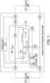
- FIG. 1 depicts a hybrid circuit protection device 100 in an example embodiment.
- protection device 100 couples one or more DC loads 102 to a DC source 104 and provides protection and fault current limiting capabilities between DC source 104 and DC loads 102.
- protection device 100 includes a controller 106, which controls the operation of protection device 100, a main switch 108 (also referred to as a main breaker), an auxiliary switch 110, a diode 112, an inductor 114, and one or more sensors 116.
- Protection device 100 further includes input terminals 118, 119 coupled to DC source 104 and output terminals 120, 121 coupled to DC load 102.
- Input terminal 119 and output terminal 121 are depicted as sharing a common circuit path, although input terminal 119 and output terminal 121 may be electrically isolated from each other in other embodiments.
- auxiliary switch 110, diode 112, and inductor 114 form a switching network 132 that is coupled in parallel with main switch 108.
- main switch 108 During normal operation, main switch 108 is closed and provides a low-loss current path between DC source 104 and DC loads 102. Auxiliary switch 110 is open during normal operation, resulting in switching network 132 being deactivated. If a fault is detected (e.g., if sensors 116 detect a fault current between DC source 104 and DC loads 102 that is greater than a threshold value), main switch 108 is opened (e.g., by controller 106 or independently by main switch 108 itself). In some embodiments, main switch 108 is a mechanical breaker, and an optional solid-state breaker 122 is in series with main switch 108 to reduce the turn-off time normally associated with a mechanical version of main switch 108.
- Controller 106 then activates switching network 132 by operating auxiliary switch 110 on and off over a switching period to current-limit the fault current from DC source 104 to DC loads 102 to a value that is less than the initial value of the fault current. For example, if the trip current value of main switch 108 is 150 Amps and the initial fault current value is 550 Amps, main switch 108 trips open. Switching network 132 operates to current-limit the fault current to a value less than 550 Amps, e.g., 250 Amps, which allows DC loads 102 to continue to be powered by DC source 104. Depending the power requirements of DC loads 102, DC loads 102 may continue to operate normally during the fault. For example, DC loads 102 may include DC/DC or DC/AC converters, which may continue to operate normally even if an input voltage at the DC/DC or DC/AC converters is depressed during the fault.
- auxiliary switch 110 When auxiliary switch 110 is on during a switching period set by controller 106, DC source 104 is electrically coupled to DC loads 102 in series through auxiliary switch 110 and inductor 114. When auxiliary switch 110 is off during the switching period, the current to DC load 102 is conducted by diode 112 and inductor 114. Generally, auxiliary switch 110, diode 112, and inductor 114 form a buck regulator that is operated by controller 106 to current-limit the fault current supplied to DC loads 102. In some embodiments, controller 106 uses a Pulse Width Modulation (PWM) control scheme to current-limit the fault current supplied to DC loads 102. In some embodiments, protection device 100 includes mechanical disconnects 124 that are used to galvanically isolate protection device 100 during maintenance.
- PWM Pulse Width Modulation
- protection device 100 provides a continuous limited current flow from DC source 104 to DC loads 102 during fault conditions, thereby enabling limited functionality at DC loads 102 even in the presence of fault. For example, depending on the limited fault current supplied by protection device 100 and the electrical power utilized by DC loads 102, DC loads 102 may continue to operate normally while the fault is identified and either cleared or isolated, thereby minimizing the disruption to DC loads 102 during faults.
- protection device 100 includes a network interface 126, which provides networking capabilities to protection device 100.
- Network interface 126 is used by controller 106, in some embodiments, to coordinate activities between different protection devices 100 in an electrical distribution system.
- Network interface 126 may include wired or wireless interfaces in various embodiments.
- controller 106 includes any system, component, or device which performs the functionality described herein for controller 106.
- controller includes a processor 128 coupled to a memory 130.
- Main switch 108 includes any system, component, or device which operates to disconnect input terminal 118 from output terminal 120 in response to a fault detected by protection device 100. In some embodiments, main switch 108 operates independently of controller 106 to disconnect input terminal 118 from output terminal 120 (e.g., utilizing information directly from sensors 116).
- main switch 108 operates under the direction of controller 106 in response to controller 106 detecting the fault (e.g., utilizing sensors 116).
- main switch 108 is a mechanical switch, which provides a low-loss forward conduction path between input terminal 118 and output terminal 120.
- main switch 108 is a low-loss solid-state switch.
- main switch 108 includes one or more Insulated-Gate Bipolar Transistors (IGBTs), Reverse Blocking-Integrated Gate Commutated Thyristors (RB-IGCTs), Silicon-Carbide Metal-Oxide-Semiconductor Field-Effect Transistors (SiC MOSFETs), Gallium Nitride (GAN) FETs, etc.
- IGBTs Insulated-Gate Bipolar Transistors
- RB-IGCTs Reverse Blocking-Integrated Gate Commutated Thyristors
- SiC MOSFETs Silicon-Carbide Metal-Oxide-Semiconductor Field-Effect Transistors
- GAN Gallium Nitride
- Auxiliary switch 110 includes any system, component, or device that is switchable by controller 106 to provide a limited current to DC loads 102 during a fault.
- Auxiliary switch 110 includes one or more IGBTs, RB-IGCTs, SiC MOSFETs, GAN FETs, etc., in various embodiments.
- Diode 112 includes any system, component, or device which operates to selectively conduct current when auxiliary switch 110 is off during a switching period.
- Diode 112 includes an active switching element in some embodiments.
- Diode 112 may be replaced by a solid-state switch in some embodiments, which is controlled by controller 106 to selectively conduct current during the off interval of the switching period when protection device 100 operates in a buck mode to supply a limited fault current to DC loads 102.
- Inductor 114 includes any system, component, or device which provides an inductance for storing energy during the on interval of the switching period for protection device 100.
- Sensors 116 measure a current and/or voltage at protection device 100.
- Sensors 116 are coupled to input terminal 118 and output terminal 120 in FIG. 1 , but sensors 116 may be, in addition or instead of, coupled to different sensing points in protection device 100 in other embodiments.
- sensors 116 include any system, component, or device which measures information indicative of a fault or representative of a fault, such as a current traversing through protection device 100 between DC source 104 and DC loads 102, a voltage at input terminal 118 and/or input terminal 119, a voltage at output terminal 120 and/or output terminal 121, harmonic noise measured at input terminals 118, 119 and/or output terminals 120, 121, etc.
- solid-state breaker 122 includes any system, component, or device which operates to selectively open a circuit path between input terminal 118 and output terminal 120.
- Solid-state breaker 122 may include any type of solid-state device previously described for main switch 108 and auxiliary switch 110.
- protection device 100 includes mechanical disconnects 124 in some embodiments to galvanically isolate protection device 100.
- mechanical disconnects 124 include any system, component, or device which selectively provides galvanic isolation to protection device 100.
- Mechanical disconnect 124 may be manually operated by a service technician during maintenance in some embodiments or controlled by controller 106 in other embodiments.
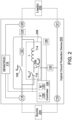
- FIG. 2 depicts another hybrid circuit protection device 200 in another example embodiment.
- protection device 200 couples one or more loads 202 to a source 204.
- source 204 may be a DC source or an AC source and loads 202 may be DC loads or AC loads.
- diode 112 (see FIG. 1 ) is replaced with an auxiliary switch 206, which includes any type of solid-state switch previously described.
- Auxiliary switches 110, 206, and inductor 114 collectively form a switching network 208 for protection device 200.
- Controller 106 operates switching network 208 in this embodiment to provide bi-directional limited fault current to either source 204 or loads 202. For example, during a fault at loads 202, main switch 108 is opened and controller 106 operates auxiliary switches 110, 206 to current-limit the fault current supplied to loads 202, similar to the functionality previously described for protection device 100 of FIG. 1 . During a fault at source 204, main switch 108 is opened and controller 106 operates auxiliary switches 110, 206 to current limit the fault current supplied to source 204.
- protection device 200 operates to current-limit the AC fault current supplied by the input capacitance of the AC/DC converters back to source 204.
- protection device 200 operates to current-limit the DC fault current supplied by the input capacitance of the AC/DC converters back to source 204.
- the limited fault current supplied to loads 202 or source 204 includes DC current and AC current.
- Providing bi-directional current-limited fault currents in hybrid electrical distribution systems advantageously allows protection device 200 to be used for both AC and DC protection, reducing the number of different types of protection devices in a hybrid electrical distribution system.
- FIG. 3 depicts a hybrid electrical distribution system 300 in an example embodiment
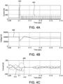
- FIGS. 4A, 4B, and 4C depict simulated current and voltage waveforms in the distribution system 300 during a fault
- distribution system 300 includes an AC source 302, which supplies power to an AC/DC converter 304.
- AC/DC converter 304 is coupled to a DC bus 306 via protection device 100, 200.
- a first load 308 is coupled to DC bus 306 via a first fuse 310 and a second load 312 is coupled to DC bus 306 via a second fuse 314.
- a fault current 402 see FIG. 4A
- main switch 108 initially rises to a high current level (e.g., 500A in this simulation, see FIG.
- a high current level e.g., 500A in this simulation, see FIG.
- Protection device 100, 200 opens main switch 108, and operates to supply a current-limited fault current 404 (see FIG. 4A ) to DC bus 306, which stabilizes voltage 406 on DC bus 306 and reduces diode currents 408, 410, 412 in AC/DC converter 304.
- Voltage 406 on DC bus 306 in the simulation is less than its initial value of 40,000 volts, but it is sufficient in this example to ensure the reduced rating operation of second load 312 during fault 316.
- main switch 108 is a mechanical device that does not perform re-closing operations to attempt to clear fault 316.
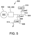
- FIG. 5 depicts another hybrid electrical distribution system 500 in an example embodiment
- FIGS. 6A and 6B depict simulated current waveforms in distribution system 500 during a fault
- distribution system 500 includes a DC source 502, which is coupled to a DC bus 504 via protection device 100, 200.
- a first load 506 is coupled to DC bus 504 via a first fuse 508 and a second load 510 is coupled to DC bus 504 via a second fuse 512.
- a fault 514 present at first load 506 a current 602 through main switch 108 initially rises to a high level (e.g., 150A in this simulation, see FIG. 6A ).
- Main switch 108 is a solid-state device in this simulation, and main switch 108 is repetitively opened and closed (e.g., either under direction of controller 106 or automatically by main switch 108 itself) in order to try and clear fault 514.
- FIG. 6B depicts a first current 604 at first load 506 and a second current 606 at second load 510 during fault 514 (see FIG. 6B ).
- protection device 100, 200 opens main switch 108, and operates to supply a current-limited fault current 608 (e.g., at a 1 Kilohertz switching frequency, see FIG. 6A ) to DC bus 504.
- a current-limited fault current 608 e.g., at a 1 Kilohertz switching frequency, see FIG. 6A
- FIG. 7 depicts another hybrid electrical distribution system 700 in an example embodiment
- FIG. 8 depicts a simulated voltage waveform in distribution system 700 during a fault
- distribution system 700 includes a DC source 702, which is coupled to a DC bus 704 via protection device 100, 200.
- a first load 706 is coupled to DC bus 704 via a first fuse 708 and a second load 710 is coupled to DC bus 704 via a second fuse 712.
- a DC/DC converter 714 is coupled to DC bus 704 and supplies a third load 716.
- an output voltage 802 of DC/DC converter 714 initially dips at T 0 when main switch 108 is opened and protection device 100, 200 supplies DC bus 704 with a limited fault current.
- Output voltage 802 of DC/DC converter 714 recovers and continues to supply third load 716 with electrical power during fault 718.
- FIG. 9 depicts another hybrid electrical distribution system 900 in an example embodiment.
- AC sources 902 are electrically coupled to an AC bus 904 via protection devices 200
- AC loads 906 are electrically coupled to AC bus 904 via fuses 908, and an AC/DC converter 910 has an input coupled to AC bus 904.
- AC/DC converter 910 is electrically coupled to a DC bus 912 via protection device 100, 200.
- a DC source 914 is also coupled to DC bus 912 via protection device 100, 200.
- DC loads 916 are electrically coupled to DC bus 912 via fuses 908.
- protection devices 100, 200 are placed at the feeders and sources 902, 914 in order to limit fault current contributions from sources 902, 914.
- downstream healthy loads can maintain full or reduced rated operation with improved voltage inputs.
- protection devices 100, 200 react to the fault and start to current-limit the fault current.
- high fault currents do not flow through the upstream and downstream fault paths and thus prevent damages to equipment and devices.
- a reduced or even full rated operation can be maintained for the rest of healthy loads in distribution system 900.
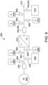
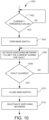
- FIG. 10 is a flow chart of a method 1000 for current-limiting a fault current between a source and a load in an example embodiment.
- Method 1000 will be discussed with respect to protection device 100, 200, although method 1000 may be performed by other devices, not shown.
- the steps of method 1000 are not all inclusive, and method 1000 may include other steps, not shown. Further, the steps of method 1000 may be performed in a different order.
- main switch 108 is closed, and the switching network 132, 208 is deactivated. If a fault occurs, then an initial value of the fault current rises to a high level, higher than a threshold value or trip current value (see step 1002), and main switch 108 then opens (see step 1004). Controller 106 operates switching network 132, 208 to current-limit the fault current to less than its initial value (see step 1006). For example, the fault current rises to about 1100 Amps, which is higher than a trip value of 250 Amps for main switch 108, causing main switch 108 to open.
- Controller 106 operates switching network 132, 208 to current-limit the initial 1100 Amp fault current to a value less than 1100 Amps.
- controller 106 operates switching network 132, 208 (e.g., by modifying the duty cycle of auxiliary switch 110 (see FIG. 1 ) and/or auxiliary switch 206) to current-limit the fault current to 550 Amps.
- main switch 108 is closed (see step 1010) and controller 106 deactivates switching network 132, 208 (see step 1012).
- Protection device 100, 200 returns to normal operation by providing a low-loss current path between sources and loads through main switch 108.
- An example technical effect of the apparatus and methods described herein includes one or more of: (a) improved performance using mechanical breakers or low-loss solid-state switches during normal operation; (b) current-limiting fault currents during faults; and (c) continuing to supply downstream loads during faults to minimize the disruption to the downstream loads during faults.
Landscapes
- Engineering & Computer Science (AREA)
- Power Engineering (AREA)
- Emergency Protection Circuit Devices (AREA)
- Direct Current Feeding And Distribution (AREA)
- Control Of Electrical Variables (AREA)
Abstract
Description
- This invention was made with government support under contract number DE-AC02-06CH11357, awarded by the Department of Energy. The government has certain rights in this invention.
- The field of the disclosure relates to circuit breakers, and more particularly, to hybrid circuit breakers that include fault current limiters.
- Circuit breakers are devices which are implemented in a circuit path to protect downstream loads on a branch circuit during faults. During fault conditions at a downstream load, circuit breakers are designed to trip open and de-energize the branch being fed by the circuit breaker. However, de-energizing the branch may also de-energize other loads on the branch, which is undesirable, especially in Direct Current (DC) distribution systems.
- Thus, it is desirable to improve the operation and performance of circuit breakers, and more specifically, improve the operation and performance of circuit breakers used in DC distribution systems.
- In one aspect, a hybrid circuit protection device for current-limiting a fault current between a source and a load during a fault is provided. The hybrid circuit protection device includes an input configured to couple to the source, an output configured to couple to the load, a return configured to couple the source to the load, a main switch configured to selectively couple the input to the output, a switching network coupled in parallel with the main switch, and a controller. The controller is configured to determine that the main switch has opened in response to the fault current, where the fault current has an initial value, and activate the switching network to current-limit the fault current to less than the initial value during the fault.
- In another aspect, a method operable by a hybrid circuit protection device for current-limiting a fault current between a source coupled to an input of the hybrid circuit protection device and a load coupled to an output of the hybrid circuit protection device during a fault is provided. The method includes determining if an initial value of the fault current through the main switch is greater than a threshold value, where the main switch selectively couples the input with the output, and responsive to determining that the initial value of the fault current is greater than the threshold value, opening the main switch, and activating a switching network coupled in parallel with the main switch to current-limit the fault current to less than the initial value during the fault.
- In another aspect, a hybrid circuit protection device for current-limiting a fault current between a source and a load during a fault is provided. The hybrid circuit protection device includes a first input terminal and a second input terminal configured to couple to the source, a first output terminal and a second output terminal configured to couple to the load, a main switch configured to selectively couple the first input terminal with the first output terminal, and a switching network. The switching network includes a solid-state switch in series with an inductor, the solid-state switch in series with the inductor coupling the first input terminal with the first output terminal. The switching network further includes a device forming a selective conduction path from a junction between the solid-state switch and the inductor to the second input terminal and the second output terminal. The hybrid circuit protection device further includes a controller configured to determine that the main switch has opened in response to the fault current, where the fault current has an initial value, and modify a duty cycle of the sold-state switch to current-limit the fault current to less than the initial value during the fault.
- These and other features, aspects, and advantages of the present disclosure will become better understood when the following detailed description is read with reference to the accompanying drawings in which like characters represent like parts throughout the drawings, wherein:
-
FIG. 1 depicts a hybrid circuit protection device in an example embodiment. -
FIG. 2 depicts another hybrid circuit protection device in an example embodiment. -
FIG. 3 depicts a hybrid electrical distribution system in an example embodiment. -
FIGS. 4A, 4B, and 4C depict simulated current and voltage waveforms in the distribution system ofFIG. 3 during a fault. -
FIG. 5 depicts another hybrid electrical distribution system in an example embodiment. -
FIGS. 6A and 6B depict simulated current waveforms in the distribution system ofFIG. 5 during a fault. -
FIG. 7 depicts another hybrid electrical distribution system in an example embodiment. -
FIG. 8 depicts a simulated voltage waveform in the distribution system ofFIG. 7 during a fault. -
FIG. 9 depicts another hybrid electrical distribution system in an example embodiment. -
FIG. 10 is a flow chart of a method for current-limiting a fault current between a source and a load during a fault in an example embodiment. - Unless otherwise indicated, the drawings provided herein are meant to illustrate features of embodiments of this disclosure. These features are believed to be applicable in a wide variety of systems comprising one or more embodiments of this disclosure. As such, the drawings are not meant to include all conventional features known by those of ordinary skill in the art to be required for the practice of the embodiments disclosed herein.
- In the following specification and the claims, reference will be made to a number of terms, which shall be defined to have the following meanings.
- The singular forms "a", "an", and "the" include plural references unless the context clearly dictates otherwise.
- "Optional" or "optionally" means that the subsequently described event or circumstance may or may not occur, and that the description includes instances where the event occurs and instances where it does not.
- Approximating language, as used herein throughout the specification and claims, may be applied to modify any quantitative representation that could permissibly vary without resulting in a change in the basic function to which it is related. Accordingly, a value modified by a term or terms, such as "about", "approximately", and "substantially", are not to be limited to the precise value specified. In at least some instances, the approximating language may correspond to the precision of an instrument for measuring the value. Here and throughout the specification and claims, range limitations may be combined and/or interchanged, such ranges are identified and include all the sub-ranges contained therein unless context or language indicates otherwise.
- As used herein, the terms "processor" and "computer," and related terms, e.g., "processing device," "computing device," and "controller" are not limited to just those integrated circuits referred to in the art as a computer, but broadly refers to a microcontroller, a microcomputer, an analog computer, a programmable logic controller (PLC), an application specific integrated circuit (ASIC), and other programmable circuits, and these terms are used interchangeably herein. In the embodiments described herein, "memory" may include, but is not limited to, a computer-readable medium, such as a random-access memory (RAM), a computer-readable non-volatile medium, such as a flash memory. Alternatively, a floppy disk, a compact disc - read only memory (CD-ROM), a magneto-optical disk (MOD), and/or a digital versatile disc (DVD) may also be used. Also, in the embodiments described herein, additional input channels may be, but are not limited to, computer peripherals associated with an operator interface such as a touchscreen, a mouse, and a keyboard. Alternatively, other computer peripherals may also be used that may include, for example, but not be limited to, a scanner. Furthermore, in the example embodiment, additional output channels may include, but not be limited to, an operator interface monitor or heads-up display. Some embodiments involve the use of one or more electronic or computing devices. Such devices typically include a processor, processing device, or controller, such as a general purpose central processing unit (CPU), a graphics processing unit (GPU), a microcontroller, a reduced instruction set computer (RISC) processor, an ASIC, a programmable logic controller (PLC), a field programmable gate array (FPGA), a digital signal processing (DSP) device, and/or any other circuit or processing device capable of executing the functions described herein. The methods described herein may be encoded as executable instructions embodied in a computer readable medium, including, without limitation, a storage device and/or a memory device. Such instructions, when executed by a processing device, cause the processing device to perform at least a portion of the methods described herein. The above examples are not intended to limit in any way the definition and/or meaning of the term processor and processing device.
- Renewable energy sources and energy storage are becoming more prevalent in electrical distribution systems. As renewable energy sources and energy storage are typically Direct Current (DC), their integration into a DC distribution is more efficient, more reliable, and less expensive than in an Alternating Current (AC) distribution. Therefore, the traditional pure AC distribution system potentially can evolve into a hybrid AC and DC distribution system. In a conventional AC distribution protection scheme, reclosers or circuit breakers are installed at substations or feeders, and fuses are installed at laterals of each feeder. The feeder reclosers or breakers react to temporary faults to open and protect downstream fuses. The feeder reclosers or breakers fail to reclose at permanent faults and the downstream fuses close to the faults melt. Therefore, customers at laterals may experience a temporary loss of power due to the opening of the feeder reclosers or breakers. This fuse-saving protection design is low-loss, low-cost, and is suitable for a high occurrence of temporary faults of conventional AC distribution feeders.
- With the integration of renewable energy sources and energy storage into a distribution system, a section of a distribution system may become a DC distribution system for easy and efficient integration. An interfacing converter maybe be utilized to integrate the AC and DC portions of the distribution system. A protection scheme for a DC distribution system may consider the low-loss, low-cost, and high temporary fault occurrence of distribution protection. AC and DC fault currents have different features, including different time constants. In a hybrid AC and DC distribution, the protection coordination between AC and DC protection may also be designed in consideration of different fault current time constants and protection devices in AC and DC subsystems.
- In the embodiments described herein, hybrid circuit protection devices are disclosed that satisfy the protection speed and coordination constraints between AC and DC distribution systems. Further, since the conventional distribution protection is not selective at lateral temporary faults, the hybrid circuit protection devices disclosed herein provide selectivity. In this regard, the downtime of the distribution is reduced, and the system reliability is improved.
- More specifically, the pending application discloses hybrid circuit protection devices that include a fault current limiting capability. During normal operation, currents flow through a main breaker or a main switch (e.g., a mechanical breaker or low-loss solid state breaker) and the protected system operates with high efficiency. During a fault, a switching network in parallel with the main breaker is operated to current-limit the fault current to the downstream loads. The fault currents are current-limited and thus prevent damage due to high fault currents to protected equipment and devices. Concurrently, at least a reduced rated power is supplied to the downstream loads. A fuse saving principle of a conventional low-cost distribution protection is still applicable and the system reliability is improved as the loads may still operate at a reduced or a full rated power during the fault current limiting operating state.
-
FIG. 1 depicts a hybridcircuit protection device 100 in an example embodiment. In this embodiment,protection device 100 couples one or more DC loads 102 to aDC source 104 and provides protection and fault current limiting capabilities betweenDC source 104 and DC loads 102. In this embodiment,protection device 100 includes acontroller 106, which controls the operation ofprotection device 100, a main switch 108 (also referred to as a main breaker), anauxiliary switch 110, adiode 112, aninductor 114, and one ormore sensors 116.Protection device 100 further includesinput terminals DC source 104 andoutput terminals DC load 102.Input terminal 119 andoutput terminal 121 are depicted as sharing a common circuit path, althoughinput terminal 119 andoutput terminal 121 may be electrically isolated from each other in other embodiments. In this embodiment,auxiliary switch 110,diode 112, andinductor 114 form aswitching network 132 that is coupled in parallel withmain switch 108. - During normal operation,
main switch 108 is closed and provides a low-loss current path betweenDC source 104 and DC loads 102.Auxiliary switch 110 is open during normal operation, resulting in switchingnetwork 132 being deactivated. If a fault is detected (e.g., ifsensors 116 detect a fault current betweenDC source 104 and DC loads 102 that is greater than a threshold value),main switch 108 is opened (e.g., bycontroller 106 or independently bymain switch 108 itself). In some embodiments,main switch 108 is a mechanical breaker, and an optional solid-state breaker 122 is in series withmain switch 108 to reduce the turn-off time normally associated with a mechanical version ofmain switch 108.Controller 106 then activates switchingnetwork 132 by operatingauxiliary switch 110 on and off over a switching period to current-limit the fault current fromDC source 104 to DC loads 102 to a value that is less than the initial value of the fault current. For example, if the trip current value ofmain switch 108 is 150 Amps and the initial fault current value is 550 Amps,main switch 108 trips open.Switching network 132 operates to current-limit the fault current to a value less than 550 Amps, e.g., 250 Amps, which allows DC loads 102 to continue to be powered byDC source 104. Depending the power requirements of DC loads 102, DC loads 102 may continue to operate normally during the fault. For example, DC loads 102 may include DC/DC or DC/AC converters, which may continue to operate normally even if an input voltage at the DC/DC or DC/AC converters is depressed during the fault. - When
auxiliary switch 110 is on during a switching period set bycontroller 106,DC source 104 is electrically coupled to DC loads 102 in series throughauxiliary switch 110 andinductor 114. Whenauxiliary switch 110 is off during the switching period, the current to DC load 102 is conducted bydiode 112 andinductor 114. Generally,auxiliary switch 110,diode 112, andinductor 114 form a buck regulator that is operated bycontroller 106 to current-limit the fault current supplied to DC loads 102. In some embodiments,controller 106 uses a Pulse Width Modulation (PWM) control scheme to current-limit the fault current supplied to DC loads 102. In some embodiments,protection device 100 includesmechanical disconnects 124 that are used to galvanically isolateprotection device 100 during maintenance. Generally,protection device 100 provides a continuous limited current flow fromDC source 104 to DC loads 102 during fault conditions, thereby enabling limited functionality at DC loads 102 even in the presence of fault. For example, depending on the limited fault current supplied byprotection device 100 and the electrical power utilized byDC loads 102, DC loads 102 may continue to operate normally while the fault is identified and either cleared or isolated, thereby minimizing the disruption to DC loads 102 during faults. In some embodiments,protection device 100 includes anetwork interface 126, which provides networking capabilities toprotection device 100.Network interface 126 is used bycontroller 106, in some embodiments, to coordinate activities betweendifferent protection devices 100 in an electrical distribution system.Network interface 126 may include wired or wireless interfaces in various embodiments. - In
FIG. 1 ,protection device 100 has been simplified for purposes of discussion, andprotection device 100 includes different configurations in other embodiments. In this regard,controller 106 includes any system, component, or device which performs the functionality described herein forcontroller 106. In some embodiments, controller includes aprocessor 128 coupled to amemory 130.Processor 128, in some embodiments, executes instructions stored inmemory 130 in order to perform the functions described herein forcontroller 106.Main switch 108 includes any system, component, or device which operates to disconnectinput terminal 118 fromoutput terminal 120 in response to a fault detected byprotection device 100. In some embodiments,main switch 108 operates independently ofcontroller 106 to disconnectinput terminal 118 from output terminal 120 (e.g., utilizing information directly from sensors 116). In other embodiments,main switch 108 operates under the direction ofcontroller 106 in response tocontroller 106 detecting the fault (e.g., utilizing sensors 116). In some embodiments,main switch 108 is a mechanical switch, which provides a low-loss forward conduction path betweeninput terminal 118 andoutput terminal 120. In other embodiments,main switch 108 is a low-loss solid-state switch. In embodiments wheremain switch 108 is a low-loss solid state switch,main switch 108 includes one or more Insulated-Gate Bipolar Transistors (IGBTs), Reverse Blocking-Integrated Gate Commutated Thyristors (RB-IGCTs), Silicon-Carbide Metal-Oxide-Semiconductor Field-Effect Transistors (SiC MOSFETs), Gallium Nitride (GAN) FETs, etc. -
Auxiliary switch 110 includes any system, component, or device that is switchable bycontroller 106 to provide a limited current to DC loads 102 during a fault.Auxiliary switch 110 includes one or more IGBTs, RB-IGCTs, SiC MOSFETs, GAN FETs, etc., in various embodiments.Diode 112 includes any system, component, or device which operates to selectively conduct current whenauxiliary switch 110 is off during a switching period.Diode 112 includes an active switching element in some embodiments. For instance,Diode 112 may be replaced by a solid-state switch in some embodiments, which is controlled bycontroller 106 to selectively conduct current during the off interval of the switching period whenprotection device 100 operates in a buck mode to supply a limited fault current to DC loads 102. -
Inductor 114 includes any system, component, or device which provides an inductance for storing energy during the on interval of the switching period forprotection device 100.Sensors 116 measure a current and/or voltage atprotection device 100.Sensors 116 are coupled to input terminal 118 andoutput terminal 120 inFIG. 1 , butsensors 116 may be, in addition or instead of, coupled to different sensing points inprotection device 100 in other embodiments. In this regard,sensors 116 include any system, component, or device which measures information indicative of a fault or representative of a fault, such as a current traversing throughprotection device 100 betweenDC source 104 and DC loads 102, a voltage atinput terminal 118 and/orinput terminal 119, a voltage atoutput terminal 120 and/oroutput terminal 121, harmonic noise measured atinput terminals output terminals - In embodiments where solid-
state breaker 122 is used in combination with a mechanical version ofmain switch 108, solid-state breaker 122 includes any system, component, or device which operates to selectively open a circuit path betweeninput terminal 118 andoutput terminal 120. Solid-state breaker 122 may include any type of solid-state device previously described formain switch 108 andauxiliary switch 110. - As discussed above,
protection device 100 includesmechanical disconnects 124 in some embodiments to galvanically isolateprotection device 100. In this regard,mechanical disconnects 124 include any system, component, or device which selectively provides galvanic isolation toprotection device 100.Mechanical disconnect 124 may be manually operated by a service technician during maintenance in some embodiments or controlled bycontroller 106 in other embodiments. -
FIG. 2 depicts another hybridcircuit protection device 200 in another example embodiment. In this embodiment,protection device 200 couples one ormore loads 202 to asource 204. In this embodiment,source 204 may be a DC source or an AC source and loads 202 may be DC loads or AC loads. In this embodiment, diode 112 (seeFIG. 1 ) is replaced with anauxiliary switch 206, which includes any type of solid-state switch previously described.Auxiliary switches inductor 114 collectively form aswitching network 208 forprotection device 200. -
Controller 106 operates switchingnetwork 208 in this embodiment to provide bi-directional limited fault current to eithersource 204 or loads 202. For example, during a fault atloads 202,main switch 108 is opened andcontroller 106 operatesauxiliary switches loads 202, similar to the functionality previously described forprotection device 100 ofFIG. 1 . During a fault atsource 204,main switch 108 is opened andcontroller 106 operatesauxiliary switches source 204. For example, ifloads 202 include AC/DC converters with a high input capacitance, and a fault atsource 204 occurs (an AC source in this example), thenprotection device 200 operates to current-limit the AC fault current supplied by the input capacitance of the AC/DC converters back tosource 204. In another example, ifloads 202 include DC/AC converters with a high input capacitance, and a fault atsource 204 occurs (a DC source in this example), thenprotection device 200 operates to current-limit the DC fault current supplied by the input capacitance of the AC/DC converters back tosource 204. - In either case, the limited fault current supplied to
loads 202 orsource 204 includes DC current and AC current. Providing bi-directional current-limited fault currents in hybrid electrical distribution systems advantageously allowsprotection device 200 to be used for both AC and DC protection, reducing the number of different types of protection devices in a hybrid electrical distribution system. -
FIG. 3 depicts a hybridelectrical distribution system 300 in an example embodiment, andFIGS. 4A, 4B, and 4C depict simulated current and voltage waveforms in thedistribution system 300 during a fault. In this embodiment,distribution system 300 includes anAC source 302, which supplies power to an AC/DC converter 304. AC/DC converter 304 is coupled to aDC bus 306 viaprotection device first load 308 is coupled toDC bus 306 via afirst fuse 310 and asecond load 312 is coupled toDC bus 306 via asecond fuse 314. With afault 316 present atfirst load 308, a fault current 402 (seeFIG. 4A ) throughmain switch 108 initially rises to a high current level (e.g., 500A in this simulation, seeFIG. 4A ). Initially, avoltage 406 onDC bus 306 dips due the high initial value of fault current 402 (seeFIG. 4B ), anddiode currents DC converter 304 rise to a high level (seeFIG. 4C ).Protection device main switch 108, and operates to supply a current-limited fault current 404 (seeFIG. 4A ) toDC bus 306, which stabilizesvoltage 406 onDC bus 306 and reducesdiode currents DC converter 304.Voltage 406 onDC bus 306 in the simulation is less than its initial value of 40,000 volts, but it is sufficient in this example to ensure the reduced rating operation ofsecond load 312 duringfault 316. In this example,main switch 108 is a mechanical device that does not perform re-closing operations to attempt toclear fault 316. -
FIG. 5 depicts another hybridelectrical distribution system 500 in an example embodiment, andFIGS. 6A and 6B depict simulated current waveforms indistribution system 500 during a fault. In this embodiment,distribution system 500 includes aDC source 502, which is coupled to aDC bus 504 viaprotection device first load 506 is coupled toDC bus 504 via afirst fuse 508 and asecond load 510 is coupled toDC bus 504 via asecond fuse 512. With afault 514 present atfirst load 506, a current 602 throughmain switch 108 initially rises to a high level (e.g., 150A in this simulation, seeFIG. 6A ).Main switch 108 is a solid-state device in this simulation, andmain switch 108 is repetitively opened and closed (e.g., either under direction ofcontroller 106 or automatically bymain switch 108 itself) in order to try andclear fault 514.FIG. 6B depicts a first current 604 atfirst load 506 and a second current 606 atsecond load 510 during fault 514 (seeFIG. 6B ). Aftermain switch 108 is reclosed twice,protection device main switch 108, and operates to supply a current-limited fault current 608 (e.g., at a 1 Kilohertz switching frequency, seeFIG. 6A ) toDC bus 504. -
FIG. 7 depicts another hybridelectrical distribution system 700 in an example embodiment, andFIG. 8 depicts a simulated voltage waveform indistribution system 700 during a fault. In this embodiment,distribution system 700 includes aDC source 702, which is coupled to aDC bus 704 viaprotection device first load 706 is coupled toDC bus 704 via afirst fuse 708 and asecond load 710 is coupled toDC bus 704 via asecond fuse 712. A DC/DC converter 714 is coupled toDC bus 704 and supplies athird load 716. With afault 718 present atfirst load 706, anoutput voltage 802 of DC/DC converter 714 initially dips at T0 whenmain switch 108 is opened andprotection device supplies DC bus 704 with a limited fault current.Output voltage 802 of DC/DC converter 714 recovers and continues to supplythird load 716 with electrical power duringfault 718. -
FIG. 9 depicts another hybridelectrical distribution system 900 in an example embodiment. In this embodiment,AC sources 902 are electrically coupled to anAC bus 904 viaprotection devices 200, AC loads 906 are electrically coupled toAC bus 904 viafuses 908, and an AC/DC converter 910 has an input coupled toAC bus 904. AC/DC converter 910 is electrically coupled to aDC bus 912 viaprotection device DC source 914 is also coupled toDC bus 912 viaprotection device DC bus 912 viafuses 908. Indistribution system 900,protection devices sources sources distribution system 900,protection devices distribution system 900. -
FIG. 10 is a flow chart of amethod 1000 for current-limiting a fault current between a source and a load in an example embodiment.Method 1000 will be discussed with respect toprotection device method 1000 may be performed by other devices, not shown. The steps ofmethod 1000 are not all inclusive, andmethod 1000 may include other steps, not shown. Further, the steps ofmethod 1000 may be performed in a different order. - Referring to
FIGS. 1 and2 , during normal operation ofprotection device main switch 108 is closed, and theswitching network main switch 108 then opens (see step 1004).Controller 106 operates switchingnetwork main switch 108, causingmain switch 108 to open.Controller 106 operates switchingnetwork controller 106 operates switchingnetwork 132, 208 (e.g., by modifying the duty cycle of auxiliary switch 110 (seeFIG. 1 ) and/or auxiliary switch 206) to current-limit the fault current to 550 Amps. - If the fault is cleared (e.g., by isolating the fault, see step 1008),
main switch 108 is closed (see step 1010) andcontroller 106 deactivates switchingnetwork 132, 208 (see step 1012).Protection device main switch 108. - An example technical effect of the apparatus and methods described herein includes one or more of: (a) improved performance using mechanical breakers or low-loss solid-state switches during normal operation; (b) current-limiting fault currents during faults; and (c) continuing to supply downstream loads during faults to minimize the disruption to the downstream loads during faults.
- Although specific features of various embodiments of the disclosure may be shown in some drawings and not in others, this is for convenience only. In accordance with the principles of the disclosure, any feature of a drawing may be referenced and/or claimed in combination with any feature of any other drawing.
- This written description uses examples to disclose the embodiments, including the best mode, and also to enable any person skilled in the art to practice the embodiments, including making and using any devices or systems and performing any incorporated methods. The patentable scope of the disclosure is defined by the claims, and may include other examples that occur to those skilled in the art. Such other examples are intended to be within the scope of the claims if they have structural elements that do not differ from the literal language of the claims, or if they include equivalent structural elements with insubstantial differences from the literal language of the claims.
Claims (15)
- A hybrid circuit protection device (100, 200) for current-limiting a fault current between a source (104, 204, 302, 502, 702, 902) and a load (202, 308, 312, 506, 510, 706, 710, 716, 906, 916) during a fault (316, 514, 718), the hybrid circuit protection device (100, 200) comprising:an input configured to couple to the source (104, 204, 302, 502, 702, 902);an output configured to couple to the load (202, 308, 312, 506, 510, 706, 710, 716, 906, 916);a return configured to couple the source (104, 204, 302, 502, 702, 902) to the load (202, 308, 312, 506, 510, 706, 710, 716, 906, 916);a main switch (108) configured to selectively couple the input to the output;a switching network (132, 208) coupled in parallel with the main switch (108); anda controller (106) configured to:determine that the main switch (108) has opened in response to the fault current, wherein the fault current has an initial value; andactivate the switching network (132, 208) to current-limit the fault current to less than the initial value during the fault (316, 514, 718).
- The hybrid circuit protection device (100, 200) of claim 1, wherein:the switching network (132, 208) comprises:an auxiliary switch (110) having a first terminal coupled to the input and a second terminal;a diode (112) having an anode coupled to the return and a cathode coupled to the second terminal of the auxiliary switch (110); andan inductor (114) having a third terminal coupled to the cathode of the diode (112) and a fourth terminal coupled to the output, andthe controller (106) is further configured to modify a duty cycle of the auxiliary switch (110) to current-limit the fault current to less than the initial value during the fault (316, 514, 718).
- The hybrid circuit protection device (100, 200) of any one of claims 1 or 2, further comprising:
at least one mechanical disconnect (124) that provides galvanic isolation for the hybrid circuit protection device (100, 200). - The hybrid circuit protection device (100, 200) of any one of claims 1 to 3, wherein:the main switch (108) comprises a mechanical breaker,the hybrid circuit protection device (100, 200) further comprises a solid-state breaker (122) in series with the mechanical breaker between the input and the output, andthe controller (106) is further configured to open the solid-state breaker (122) in response to the fault current.
- The hybrid circuit protection device (100, 200) of any one of claims 1 to 4, wherein:
the controller (106) is further configured to:determine that the main switch (108) has closed; anddeactivate the switching network (132, 208) to disable a current path through the switching network (132, 208) between the input and the output. - The hybrid circuit protection device (100, 200) of any one of claims 1 to 5, further comprising:a current sensor (116) that is configured to sense the fault current between the input and the output,wherein the controller (106) is further configured to:measure the fault current using the current sensor (116);determine whether the initial value of the fault current is greater than a threshold value; andopen the main switch (108) in response to determining that the initial value is greater than the threshold value.
- The hybrid circuit protection device (100, 200) of any one of claims 1 to 6, wherein:the switching network (132, 208) comprises:a first auxiliary switch (110) having a first terminal coupled to the input and a second terminal;a second auxiliary switch (206) having a third terminal coupled to the return and a fourth terminal coupled to the second terminal of the first auxiliary switch (110); andan inductor (114) having a fifth terminal coupled to the second terminal of the first auxiliary switch (110) and the fourth terminal of the second auxiliary switch (206), the inductor (114) having a sixth terminal coupled to the output, andthe controller (106) is further configured to modify a duty cycle of the first auxiliary switch (110) and the second auxiliary switch (206) to current-limit the fault current during the fault (316, 514, 718).
- A method (1000) operable by a hybrid circuit protection device (100, 200) for current-limiting a fault current between a source (104, 204, 302, 502, 702, 902) coupled to an input of the hybrid circuit protection device (100, 200) and a load (202, 308, 312, 506, 510, 706, 710, 716, 906, 916) coupled to an output of the hybrid circuit protection device (100, 200) during a fault (316, 514, 718), the method comprising:determining (1002) whether an initial value of the fault current through a main switch (108) is greater than a threshold value, wherein the main switch (108) selectively couples the input with the output; andresponsive to determining that the initial value of the fault current is greater than the threshold value:opening (1004) the main switch (108); andactivating (1006) a switching network (132, 208) coupled in parallel with the main switch (108) to current-limit the fault current to less than the initial value during the fault (316, 514, 718).
- The method (1000) of claim 8, further comprising:determining (1008) whether the fault (316, 514, 718) has been cleared; andresponsive to determining that the fault (316, 514, 718) has been cleared:closing (1010) the main switch (108); anddeactivating (1012) the switching network (132, 208) to disable a current path through the switching network between the input and the output.
- The method (1000) of any one of claims 8 or 9, further comprising:
modifying a duty cycle of at least one switch (110, 206) of the switching network (132, 208) to current-limit the fault current to less than the initial value during the fault (316, 514, 718). - The method (1000) of any one of claims 8 to 10, wherein:a return couples the source (104, 204, 302, 502, 702, 902) to the load (202, 308, 312, 506, 510, 706, 710, 716, 906, 916),the switching network (132, 208) comprises:an auxiliary switch (110) having a first terminal coupled to the input and a second terminal;a diode (112) having an anode coupled to the return and a cathode coupled to the second terminal of the auxiliary switch (110); andan inductor (114) having a third terminal coupled to the cathode of the diode (112) and a fourth terminal coupled to the output, andthe method (1000) further comprises modifying a duty cycle of the auxiliary switch (110) to current-limit the fault current to less than the initial value during the fault (316, 514, 718).
- The method (1000) of any one of claims 8 to 11, wherein:the main switch (108) comprises a mechanical breaker,the hybrid circuit protection device further comprises a solid-state breaker (122) in series with the mechanical breaker between the input and the output, andthe method (1000) further comprises opening the solid-state breaker (122) in response to the fault current.
- The method (1000) of any one of claims 8 to 12, wherein:the hybrid circuit protection device (100, 200) further comprises a current sensor (116) that is configured to sense the fault current between the input and the output,wherein the method (1000) further comprises:measuring (1002) the fault current using the current sensor (116);determining (1002) whether the initial value of the fault current is greater than a threshold value; andopening (1004) the main switch (108) in response to determining that the initial value is greater than the threshold value.
- The method (1000) of any one of claims 8 to 13, wherein:a return couples the source (104, 204, 302, 502, 702, 902) to the load (202, 308, 312, 506, 510, 706, 710, 716, 906, 916),the switching network (132, 208) comprises:a first auxiliary switch (110) having a first terminal coupled to the input and a second terminal;a second auxiliary switch (206) having a third terminal coupled to the return and a fourth terminal coupled to the second terminal of the first auxiliary switch (110); andan inductor (114) having a fifth terminal coupled to the second terminal of the first auxiliary switch (110) and the fourth terminal of the second auxiliary switch (206), the inductor (114) having a sixth terminal coupled to the output, andthe method (1000) further comprises modifying a duty cycle of the first auxiliary switch (110) and the second auxiliary switch (206) to current-limit the fault current during the fault (316, 514, 718).
- The method (1000) of any one of claims 8 to 14, further comprising:determining (1010) that the main switch (108) has closed; anddeactivating (1012) the switching network (132, 208) to disable a current path through the switching network (132, 208) between the input and the output.
Applications Claiming Priority (1)
| Application Number | Priority Date | Filing Date | Title |
|---|---|---|---|
| US17/557,258 US11837865B2 (en) | 2021-12-21 | 2021-12-21 | Hybrid circuit breakers |
Publications (1)
| Publication Number | Publication Date |
|---|---|
| EP4203218A1 true EP4203218A1 (en) | 2023-06-28 |
Family
ID=84535797
Family Applications (1)
| Application Number | Title | Priority Date | Filing Date |
|---|---|---|---|
| EP22213546.9A Pending EP4203218A1 (en) | 2021-12-21 | 2022-12-14 | Hybrid circuit breakers |
Country Status (4)
| Country | Link |
|---|---|
| US (1) | US11837865B2 (en) |
| EP (1) | EP4203218A1 (en) |
| JP (1) | JP2023092522A (en) |
| CN (1) | CN116316466B (en) |
Cited By (1)
| Publication number | Priority date | Publication date | Assignee | Title |
|---|---|---|---|---|
| EP4672580A1 (en) * | 2024-06-28 | 2025-12-31 | Abb Schweiz Ag | Inverter with multifunctional output protection circuit and method |
Families Citing this family (4)
| Publication number | Priority date | Publication date | Assignee | Title |
|---|---|---|---|---|
| US20240195166A1 (en) * | 2022-12-13 | 2024-06-13 | Battelle Memorial Institute | Circuit Breakers and Circuit Breaker Operational Methods |
| CN116093891B (en) * | 2023-01-09 | 2025-06-06 | 西安交通大学 | Generator circuit breaker control method based on short-circuit fault current symmetry |
| US20250273416A1 (en) * | 2024-02-23 | 2025-08-28 | Eaton Intelligent Power Limited | Solid state hybrid circuit breaker topology using dual ultrafast opening contacts |
| US12597768B2 (en) * | 2024-04-03 | 2026-04-07 | Synque Consulting Inc. | Series type hybrid circuit breaker with non-resonant current zero-crossing generation |
Citations (4)
| Publication number | Priority date | Publication date | Assignee | Title |
|---|---|---|---|---|
| US20070121257A1 (en) * | 2005-11-30 | 2007-05-31 | Arindam Maitra | Multifunction hybrid solid-state switchgear |
| US20140376140A1 (en) * | 2013-02-06 | 2014-12-25 | Xi'an Jiaotong University | Hybrid dc breaker |
| US20180138689A1 (en) * | 2016-11-11 | 2018-05-17 | Xi'an Jiaotong University | Dc circuit breaker combining magnetic induction transfer and resistance current limiting |
| US20200266624A1 (en) * | 2018-12-10 | 2020-08-20 | Eaton Intelligent Power Limited | Fault current mitigation method and system for solid state circuit breaker |
Family Cites Families (12)
| Publication number | Priority date | Publication date | Assignee | Title |
|---|---|---|---|---|
| US8174801B2 (en) * | 2009-04-01 | 2012-05-08 | Honeywell International, Inc. | Controlling arc energy in a hybrid high voltage DC contactor |
| US8553373B2 (en) * | 2011-08-25 | 2013-10-08 | Hamilton Sundstrand Corporation | Solid state power controller for high voltage direct current systems |
| CN104617567A (en) * | 2015-01-13 | 2015-05-13 | 中国矿业大学 | Novel short circuit current limiter |
| EP3157034B1 (en) * | 2015-10-13 | 2018-03-21 | General Electric Technology GmbH | Mechatronic circuit-breaker device |
| JP6706834B2 (en) * | 2016-01-21 | 2020-06-10 | 国立大学法人東京工業大学 | Circuit breaker |
| CN106374748A (en) * | 2016-10-09 | 2017-02-01 | 昂宝电子(上海)有限公司 | BUCK converter and its control method |
| EP3330992B1 (en) * | 2016-12-05 | 2019-11-20 | ABB Schweiz AG | Electrical dc switching system |
| CN107592101B (en) * | 2017-09-07 | 2019-06-04 | 电子科技大学 | A DC Solid State Circuit Breaker Based on Cathode Short-Circuit Grid Controlled Thyristor |
| CN108092243B (en) * | 2017-12-11 | 2019-10-08 | 中国科学院电工研究所 | A kind of hybrid dc circuit breaker of capacitive buffer type |
| CN108376974B (en) * | 2018-02-11 | 2019-09-03 | 国网陕西省电力公司电力科学研究院 | A distribution network relay protection system based on current-limiting step-difference coordination |
| CN110021912B (en) * | 2019-04-28 | 2020-06-23 | 山东大学 | Multi-terminal flexible direct-current power grid self-adaptive reclosing method based on hybrid direct-current circuit breaker |
| CN112003354B (en) * | 2020-09-18 | 2023-01-31 | 联正电子(深圳)有限公司 | Control circuit for charging current-limiting circuit, charging current limiter and charging and discharging circuit |
-
2021
- 2021-12-21 US US17/557,258 patent/US11837865B2/en active Active
-
2022
- 2022-12-14 EP EP22213546.9A patent/EP4203218A1/en active Pending
- 2022-12-21 JP JP2022203865A patent/JP2023092522A/en active Pending
- 2022-12-21 CN CN202211660005.8A patent/CN116316466B/en active Active
Patent Citations (4)
| Publication number | Priority date | Publication date | Assignee | Title |
|---|---|---|---|---|
| US20070121257A1 (en) * | 2005-11-30 | 2007-05-31 | Arindam Maitra | Multifunction hybrid solid-state switchgear |
| US20140376140A1 (en) * | 2013-02-06 | 2014-12-25 | Xi'an Jiaotong University | Hybrid dc breaker |
| US20180138689A1 (en) * | 2016-11-11 | 2018-05-17 | Xi'an Jiaotong University | Dc circuit breaker combining magnetic induction transfer and resistance current limiting |
| US20200266624A1 (en) * | 2018-12-10 | 2020-08-20 | Eaton Intelligent Power Limited | Fault current mitigation method and system for solid state circuit breaker |
Cited By (1)
| Publication number | Priority date | Publication date | Assignee | Title |
|---|---|---|---|---|
| EP4672580A1 (en) * | 2024-06-28 | 2025-12-31 | Abb Schweiz Ag | Inverter with multifunctional output protection circuit and method |
Also Published As
| Publication number | Publication date |
|---|---|
| US11837865B2 (en) | 2023-12-05 |
| CN116316466A (en) | 2023-06-23 |
| US20230198248A1 (en) | 2023-06-22 |
| JP2023092522A (en) | 2023-07-03 |
| CN116316466B (en) | 2026-04-14 |
Similar Documents
| Publication | Publication Date | Title |
|---|---|---|
| US11837865B2 (en) | Hybrid circuit breakers | |
| US8861162B2 (en) | High power solid state power controller (SSPC) solution for primary power distribution applications | |
| US11322926B2 (en) | Hybrid DC circuit breaker | |
| EP1811645B1 (en) | Power supply circuit protecting method and apparatus for the same | |
| US9742185B2 (en) | DC circuit breaker and method of use | |
| CN105493218B (en) | circuit breaker with hybrid switch | |
| EP2779416A2 (en) | System and method for fault protection of a motor | |
| US11588321B2 (en) | Low-voltage protection switch unit | |
| JP2011120462A (en) | Current type power converter using normally-on field effect transistor | |
| US20210175704A1 (en) | Electrical ac/dc conversion arrangement | |
| US11374391B2 (en) | Electrical AC/DC converter arrangement with an AC circuit breaker, and a method for disconnecting an AC/DC converter arrangement | |
| Solangi et al. | Selective coordination of GaN-based solid state circuit breakers | |
| JP2017195736A (en) | Power conversion device | |
| CN112783017A (en) | Integrated circuit module for circuit breakers, relays and contactors | |
| US11843242B1 (en) | High voltage DC fault detection | |
| US10209308B2 (en) | MV switching device of the electromagnetic type having an improved power drive circuit | |
| CN113039711B (en) | Method for detecting a shutdown current, electric switch and DC voltage network | |
| US9793809B1 (en) | Safety crowbar for voltage converters | |
| KR102800382B1 (en) | Overcurrent protection devices for DC networks | |
| EP4318521A1 (en) | Hybrid circuit breaker system with integrated galvanic isolating switch | |
| EP4607564A1 (en) | Switching device and method for controlling the switching device | |
| US20230187925A1 (en) | Electrical protection systems and methods having improved selectivity | |
| KR102915527B1 (en) | Apparatus capable of soft-closing for protection of dc system and method thereof | |
| US20250385506A1 (en) | Managing leakage current in solid-state circuit breakers with multiple load-to-line connections switched with microcontroller units | |
| Yoon et al. | Protection Circuit for DC Short Fault and Soft-Reclosing Operation for Protective Coordination Algorithm |
Legal Events
| Date | Code | Title | Description |
|---|---|---|---|
| PUAI | Public reference made under article 153(3) epc to a published international application that has entered the european phase |
Free format text: ORIGINAL CODE: 0009012 |
|
| STAA | Information on the status of an ep patent application or granted ep patent |
Free format text: STATUS: THE APPLICATION HAS BEEN PUBLISHED |
|
| AK | Designated contracting states |
Kind code of ref document: A1 Designated state(s): AL AT BE BG CH CY CZ DE DK EE ES FI FR GB GR HR HU IE IS IT LI LT LU LV MC ME MK MT NL NO PL PT RO RS SE SI SK SM TR |
|
| STAA | Information on the status of an ep patent application or granted ep patent |
Free format text: STATUS: REQUEST FOR EXAMINATION WAS MADE |
|
| 17P | Request for examination filed |
Effective date: 20231228 |
|
| RBV | Designated contracting states (corrected) |
Designated state(s): AL AT BE BG CH CY CZ DE DK EE ES FI FR GB GR HR HU IE IS IT LI LT LU LV MC ME MK MT NL NO PL PT RO RS SE SI SK SM TR |