EP4203187A1 - Connector device with antenna connection - Google Patents
Connector device with antenna connection Download PDFInfo
- Publication number
- EP4203187A1 EP4203187A1 EP23151313.6A EP23151313A EP4203187A1 EP 4203187 A1 EP4203187 A1 EP 4203187A1 EP 23151313 A EP23151313 A EP 23151313A EP 4203187 A1 EP4203187 A1 EP 4203187A1
- Authority
- EP
- European Patent Office
- Prior art keywords
- antenna
- audio
- connector
- external
- cable
- Prior art date
- Legal status (The legal status is an assumption and is not a legal conclusion. Google has not performed a legal analysis and makes no representation as to the accuracy of the status listed.)
- Pending
Links
Images




Classifications
-
- H—ELECTRICITY
- H01—ELECTRIC ELEMENTS
- H01R—ELECTRICALLY-CONDUCTIVE CONNECTIONS; STRUCTURAL ASSOCIATIONS OF A PLURALITY OF MUTUALLY-INSULATED ELECTRICAL CONNECTING ELEMENTS; COUPLING DEVICES; CURRENT COLLECTORS
- H01R13/00—Details of coupling devices of the kinds covered by groups H01R12/70 or H01R24/00 - H01R33/00
- H01R13/66—Structural association with built-in electrical component
- H01R13/665—Structural association with built-in electrical component with built-in electronic circuit
- H01R13/6683—Structural association with built-in electrical component with built-in electronic circuit with built-in sensor
-
- H—ELECTRICITY
- H01—ELECTRIC ELEMENTS
- H01Q—ANTENNAS, i.e. RADIO AERIALS
- H01Q1/00—Details of, or arrangements associated with, antennas
- H01Q1/12—Supports; Mounting means
- H01Q1/22—Supports; Mounting means by structural association with other equipment or articles
-
- H—ELECTRICITY
- H01—ELECTRIC ELEMENTS
- H01Q—ANTENNAS, i.e. RADIO AERIALS
- H01Q1/00—Details of, or arrangements associated with, antennas
- H01Q1/44—Details of, or arrangements associated with, antennas using equipment having another main function to serve additionally as an antenna, e.g. means for giving an antenna an aesthetic aspect
-
- H—ELECTRICITY
- H01—ELECTRIC ELEMENTS
- H01Q—ANTENNAS, i.e. RADIO AERIALS
- H01Q1/00—Details of, or arrangements associated with, antennas
- H01Q1/44—Details of, or arrangements associated with, antennas using equipment having another main function to serve additionally as an antenna, e.g. means for giving an antenna an aesthetic aspect
- H01Q1/46—Electric supply lines or communication lines
-
- H—ELECTRICITY
- H01—ELECTRIC ELEMENTS
- H01Q—ANTENNAS, i.e. RADIO AERIALS
- H01Q21/00—Antenna arrays or systems
- H01Q21/28—Combinations of substantially independent non-interacting antenna units or systems
-
- H—ELECTRICITY
- H01—ELECTRIC ELEMENTS
- H01R—ELECTRICALLY-CONDUCTIVE CONNECTIONS; STRUCTURAL ASSOCIATIONS OF A PLURALITY OF MUTUALLY-INSULATED ELECTRICAL CONNECTING ELEMENTS; COUPLING DEVICES; CURRENT COLLECTORS
- H01R27/00—Coupling parts adapted for co-operation with two or more dissimilar counterparts
- H01R27/02—Coupling parts adapted for co-operation with two or more dissimilar counterparts for simultaneous co-operation with two or more dissimilar counterparts
-
- H—ELECTRICITY
- H01—ELECTRIC ELEMENTS
- H01Q—ANTENNAS, i.e. RADIO AERIALS
- H01Q1/00—Details of, or arrangements associated with, antennas
- H01Q1/08—Means for collapsing antennas or parts thereof
- H01Q1/084—Pivotable antennas
-
- H—ELECTRICITY
- H01—ELECTRIC ELEMENTS
- H01R—ELECTRICALLY-CONDUCTIVE CONNECTIONS; STRUCTURAL ASSOCIATIONS OF A PLURALITY OF MUTUALLY-INSULATED ELECTRICAL CONNECTING ELEMENTS; COUPLING DEVICES; CURRENT COLLECTORS
- H01R2107/00—Four or more poles
-
- H—ELECTRICITY
- H01—ELECTRIC ELEMENTS
- H01R—ELECTRICALLY-CONDUCTIVE CONNECTIONS; STRUCTURAL ASSOCIATIONS OF A PLURALITY OF MUTUALLY-INSULATED ELECTRICAL CONNECTING ELEMENTS; COUPLING DEVICES; CURRENT COLLECTORS
- H01R2201/00—Connectors or connections adapted for particular applications
- H01R2201/02—Connectors or connections adapted for particular applications for antennas
Definitions
- This disclosure generally relates to audio-visual devices that are configured to attach to external antennas that, for example, are embedded in an electrical cable connected to the audio-visual device.
- a user may now have subscriptions to several different streaming video services that each provide access to a unique catalog of video.
- a user may subscribe to individual channels, services, or collections of content from many sources. Examples of these services include but are not limited to Netflix TM , Hulu TM , Amazon Instant Video TM , HBO Go TM , Showtime Anytime TM , among others.
- Each of these services provides an end user application for receiving their unique content offerings on an end user audio-visual device such as, for example, streaming media platforms.
- Such audio-visual devices may plug directly in to the video and audio inputs of a display device such as a television or computer monitor using, e.g., a High Definition Multimedia Interface (HDMI) connection.
- the audio-visual devices may receive content from the internet using, e.g., a wireless connection such as WiFi according to the IEEE 802.11 standard.
- audio-visual devices may require the use of one or more antennas to receive wireless internet information.
- antennas function better the farther away they can be placed from other, potentially interfering, components (e.g., HDMI components) of the audio-visual device.
- HDMI components e.g., HDMI components
- Various embodiments of the disclosure relate to devices, connectors, and cables that connect an audio-visual device (or other electrical device or component) to an external antenna.
- Some embodiments are directed to a device connector for connecting the audio-visual device to an external cable.
- the device connector may include a port that is configured to receive power from a source external to the audio-visual device.
- the port may also or instead be configured to receive data signals from an external source in some embodiments.
- the port could comprise a universal serial bus (USB) port or an HDMI port.
- the device connector may also include an antenna port that is configured to connect the audio-visual device to an external antenna that is, for example, part of the same cable to which the USB or HDMI port is connected.
- the device connector may include a detection mechanism that detects the presence of an antenna connection in the antenna port.
- the audio-visual device may be configured to use one or more external antennas connected via the antenna connection to send and receive, e.g., WiFi signals.
- the audio-visual device may be configured to use the one or more external antennas instead of an internal antenna.
- the audio-visual device may be configured to use the one or more external antennas in conjunction with an antenna that is internal to the audio-visual device.
- the streaming media device may include an audio-visual device portion, a cable portion that includes a power and/or data supply line and one or more antennas, and a device connector configured to connect the cable portion to the audio-visual device portion.
- the audio-visual portion, the cable portion, and the device connector may form a unitary body.
- the audio-visual portion, the cable portion, and the device connector may be detachably connectable.
- the device connector may include a detection mechanism that detects the presence of an antenna connection in the antenna port.
- the audio-visual device may be configured to use one or more external antennas connected via the antenna connection to send and receive, e.g., WiFi signals.
- the audio-visual device may be configured to use the one or more external antennas instead of an internal antenna.
- the audio-visual device may be configured to use the one or more external antennas in conjunction with an antenna that is internal to the audio-visual device.
- Some embodiments of the disclosure also include a cable for use with a streaming media device.
- the cable may include a power and/or data supply line, an antenna, and a connection portion.
- the connection portion may be coupled to the power and/or data supply line and the antenna both.
- the connection portion may also include a separate antenna connector that is electrically coupled to the antenna and a power and/or data supply connector that is electrically coupled to the power and/or data supply line.
- the connection portion in some embodiments, may also further comprise an additional antenna connector that is electrically coupled to an additional antenna. Both antennas may be physically offset from one another in various embodiments.
- FIG. 1 is a block diagram depicting an example audio-visual device 100 according to various embodiments.
- display device 100 may include one or more processors 102, a display driver 104, memory 106, and an input interface 108.
- the audio-visual device may include an antenna module 110 and a power management module 112.
- the display driver 104 of the audio-visual device 100 may be configured to output audio-visual (A/V) output to, e.g., a display device such as a television, phone, tablet, computer, monitor, or the like.
- the display driver 104 may operate under the control of processor 102 and may be configured to output A/V content via, e.g., a HDMI connection to the display (not shown).
- Memory 106 may comprise any appropriate memory storage device and may be configured to store a number of different kinds of information. For instance, in some embodiments, memory 106 may be configured to store a number of different streaming media applications for execution by processor 102 in either a compiled or un-compiled form.
- the interface 108 may be configured to accept user input from, for example, a remote control device (not shown).
- the interface 108 may include a wireless sensor (e.g., an infrared sensor) to communicate with a remote control device and to convey user input from the remote control device to the processor 102.
- a wireless sensor e.g., an infrared sensor
- the power management module 112 of audio-visual device 100 may be configured to receive electrical power from an external supply and to provide power to the various other components of the audio-visual device 100. For instance, as shown in FIG. 1 , the power management module 112 receives electrical power from port 126 and distributes the electrical power to the various components of the audio-visual device 100. Additionally, the power management module 112 may be controlled by processor 102 to, for instance, adjust the amount of power to various components or to power on and off various components of audio-visual device 100.
- the antenna module 110 may contain one or more antennas that are configured to establish a wireless connection with a remote wireless signal source such as, a wireless internet router, a Bluetooth device, or a radio device, to name a few non-limiting examples.
- the antenna module 110 may comprise one or more individual antenna integrated circuit components.
- the antenna module 110 may include antenna elements directly printed on a printed circuit board of audio-visual device 100.
- the audio-visual device 100 may also include a device connector 120.
- the device connector 120 may include a detection circuit 122, an antenna port 124, and a port 126.
- port 126 may be configured to receive power from a source external to the audio-visual device 100.
- port 126 may also or instead be configured to receive data signals from a source external to the audio-visual device.
- the port 126 can be configured to provide the received electrical power to the power management module 112, where the electrical power may be distributed to the various portions of audio-visual device 100.
- the power supply port could be any appropriate standard connection port such as a universal serial bus (USB) port, micro USB port, an AC adaptor plug, and a coaxial port, to name a few non-limiting examples.
- USB universal serial bus
- the device connector 120 may also include an antenna port 124 that is configured to connect the audio-visual device 100 to an external antenna that may be, in some embodiments, part of the same cable to which port 126 is connected.
- the electrical cable that connects to device connector 120 may comprise an HDMI cable, a USB cable, a micro USB cable, power cable, or any suitable cable that is capable of transmitting power and/or data signals.
- one or more external antennas may be embedded in the cable along the length and/or diameter of the cable and be available for use by the audio-device 100 when they are connected to the antenna port 124.
- the device connector 120 may include a detection mechanism 122 that detects the presence of an antenna connection in the antenna port 124.
- the audio-visual device 100 may be configured to use one or more external antennas connected via the antenna port 124 to send and receive, e.g., wireless signals.
- the audio-visual device 100 may be configured to use the one or more external antennas instead of an internal antenna 110.
- the audio-visual device 100 may be configured to use the one or more external antennas in conjunction with antenna module 110.
- the audio-visual device 100 may not include antenna module 110, instead relying on external antennas for wireless connectivity and communication.
- the detection mechanism 122 may send a signal to processor 102 indicating the presence or non-presence of an antenna connection at antenna port 124.
- the processor 102 may then electrically connect or disconnect the internal antenna 110 from operation in favor of one or more external antennas (eg., antennas embedded in a cable connected to the antenna port) connected to antenna port 124 depending on the particular embodiment.
- the detection mechanism 122 may be implemented as a physical switch that connects or disconnects the antenna module 110 in favor of one or more external antennas connected to antenna port 124.
- FIG. 2 is an illustration of a streaming media device 200 according to various embodiments of the disclosure.
- the streaming media device 200 may include an audio-visual device portion 212 and a cable portion 214.
- the audio-visual device portion 212 may be similar to audio-visual device 100 from FIG. 1 .
- FIG. 2 should not be construed as so limiting.
- the audio-visual device portion 212 may itself comprise audio-visual device 202 and an A/V connector 208. While FIG. 2 depicts A/V connector 208 as an HDMI connector, other embodiments may utilize different A/V connectors such as component connectors, optical connectors, USB connectors, micro USB connectors, coaxial connectors, video graphics array (VGA) connectors, digital visual interface (DVI) connectors, to name several non-limiting examples.
- A/V connector 208 may utilize different A/V connectors such as component connectors, optical connectors, USB connectors, micro USB connectors, coaxial connectors, video graphics array (VGA) connectors, digital visual interface (DVI) connectors, to name several non-limiting examples.
- the cable portion 214 may itself comprise a connector 204 and a cable 206.
- the connector 204 may operate to connect to the audio-visual device portion 212 via device connection 210 (corresponding to device connector 120 in FIG. 1 , for example).
- device connection 210 may be a permanent connection and the audio-visual portion 212 and the cable portion 214 may form a single unitary body. However, in some embodiments the device connection 210 forms a detachable connection between the audio-visual portion 212 and the cable portion 214.
- the cable 206 of cable portion 214 may connect the connector 210 (and by extension the audio-visual device portion 212) to a power supply, a data signal source, and/or one or more external antennas.
- the cable 206 may comprise a modified standard cable (e.g., a USB or HDMI cable) that also includes antenna elements connected and extending along various points.
- the connector 204 may contain external antenna elements for connection to the audio-visual device portion 212.
- FIG. 3 illustrates a portion of streaming media device 300 similar to the streaming media system illustrated in FIG. 2 .
- the streaming media device 300 contains an audio-visual device portion 212 and a cable portion 214.
- the audio-visual device portion 212 may be similar to audio-visual device 100 from FIG. 1 .
- FIG. 3 should not be construed as so limiting.
- the streaming media device 300 in FIG. 3 is shown with the audio-visual device portion 212 detached from the cable portion 214.
- Each of the audio-visual portion 212 and the cable portion 214 has a corresponding connector portion.
- the audio-visual device portion 212 has a female connector portion 224 with ports for receiving the connectors from male the male connector portion 204 of the cable portion 214.
- connection port 220 may provide power, data signals, and/or some combination of power and data signals to the audio-visual portion. While FIG. 3 depicts connection port 220 as a USB port, this is just one example of a possible kind of port that may be used. Any suitable port capable of carrying electrical power and/or data signals may be used.
- the antenna connection ports 230a and 230b may correspond to antenna port 124 shown in FIG. 1 .
- the USB port 220 may correspond to port 126.
- the connector 204 of the cable portion 214 includes male antenna connectors 232a and 232b and male connector 222.
- Male antenna connectors 232a and 232b are configured to mate with antenna ports 230a and 230b, respectively, of the connector portion 224.
- male connector 222 is configured to mate with port 220 in connector 224.
- Each of the antenna connectors 232a and 232b may be electrically connected to an external antenna that, for example, forms part of cable 206. That is, the connectors 232a and 232b may electrically connect one or more antennas that are embedded in cable 206 along its length. However, in some embodiments, one or more external antennas may be part of connector 204.
- FIG. 4 illustrates a portion of an internal configuration of streaming media device 300 similar to the streaming media system illustrated in FIG. 3 with the cover of the audio-visual device portion 212 removed.
- the streaming media device 300 contains an audio-visual device portion 212 and a cable portion 214.
- the audio-visual device portion 212 may be similar to audio-visual device 100 from FIG. 1 .
- FIG. 4 should not be construed as so limiting.
- each of the audio-visual portion 212 and the cable portion 214 has a corresponding connector portion.
- the audio-visual device portion 212 has a female connector portion 224 with ports for receiving the connectors from male the male connector portion 204 of the cable portion 214.
- the connector portion 224 of the audio-visual portion 212 is shown as having antenna connection ports 230a and 230b and a port 220.
- port 220 may comprise a USB port, a micro USB port, an HDMI port, a power port, or any suitable port that can transmit power, data signals, and/or some combination of power and data signals.
- the antenna connection ports 230a and 230b may correspond to antenna port 124 shown in FIG. 1 .
- the USB port 220 may correspond to port 126.
- the connector 204 of the cable portion 214 includes male antenna connectors 232a and 232b and male USB connector 222.
- Male antenna connectors 232a and 232b are configured to mate with antenna ports 230a and 230b, respectively, of the connector portion 224.
- male connector 222 is configured to mate with port 220 in connector 224.
- Each of the antenna connectors 232a and 232b may be electrically connected to an external antenna that, for example, forms part of cable 206.
- the external antenna may be part of connector 204.
- FIG. 4 also shows that the audio-visual device portion 212 contains an internal antenna module 240.
- the audio-visual device portion 212 may be configured to bypass the internal antenna module 240 and use, instead, one or more external antennas that are connected via connectors 232a and 232b.
- the audio-visual device portion 212 may also be configured to use the internal antenna module 240 in conjunction with one or more external antennas that are connected via connectors 232a and 232b.
- FIG. 5 depicts a connector portion 224 of an audio visual device 202 according to various embodiments of the disclosure.
- the connector portion 224 may include a connector port 220.
- connector port 220 may be a USB port, a micro USB port, and HDMI port, or any suitable port capable of carrying electrical power, data signals, and/or some combination of electrical power and data signals.
- Ports 230a and 232b are configured to receive antenna connectors (e.g., connectors 232a and 232b).
- ports 232a and 232b may be configured to receive co-axial type connectors.
- any suitable antenna connector may be employed consistent with this disclosure.
- FIG. 6 depicts a block diagram of a streaming media device 600 according to various embodiments of the disclosure.
- the streaming media device 600 may include an audio-visual device portion 212 and a cable portion 214 similar to the corresponding elements described with respect to FIG. 2 , above.
- FIG. 6 should not be construed as so limiting.
- the audio-visual device portion 212 may itself comprise audio-visual device 202 and an A/V connector 208 such as an HDMI connector, component connectors, optical connectors, USB connectors, micro USB connectors, coaxial connectors, video graphics array (VGA) connectors, digital visual interface (DVI) connectors, to name several non-limiting examples.
- A/V connector 208 such as an HDMI connector, component connectors, optical connectors, USB connectors, micro USB connectors, coaxial connectors, video graphics array (VGA) connectors, digital visual interface (DVI) connectors, to name several non-limiting examples.
- the cable portion 214 may itself comprise a connector 204 and a cable 206.
- the connector 204 may operate to connect to the audio-visual device portion 212 via device connection 210.
- device connection 210 may be a permanent connection and the audio-visual portion 212 and the cable portion 214 may form a single unitary body. However, in some embodiments the device connection 210 forms a detachable connection between the audio-visual portion 212 and the cable portion 214.
- the cable 206 of cable portion 214 may connect the connector (and by extension the audio-visual device portion 212) to a power supply, a data signal source, some combination of power supply and a data source, and/or one or more external antennas.
- the cable 206 may comprise a modified standard cable (e.g., a USB cable) that also includes antenna elements connected along various points.
- the connector 204 may contain external antenna elements for connection to the audio-visual device portion 212.
- the cable portion 214 of the streaming media device 600 also contains one or more external antennas 602a and/or 602b.
- the external antennas 602a and 602b are integrated as part of the cable 206 and may be connected to the audio-device portion 212 by, e.g., connectors such as connectors 232a and 232b.
- the external antennas 602a and 602b may linearly offset from each other by a distance d equal to a fraction or multiple of the wavelength of the carrier signal frequency.
- antennas 602a and 602b are linearly offset from each other such that distance d is around 1 ⁇ 4 of the wavelength of the frequency.
- the linear offset distance d may be around 31.25mm, or 1 ⁇ 4 of the 12.5cm wavelength.
- the following table lists example offset distances by frequency for some example embodiments of the disclosure: Frequency Wavelength Offset Distance d 2.4 GHz 12.5 cm 31.25 mm 3.6 GHz 8.33 cm 20.83 mm 4.9 GHz 6.12 cm 15.3 mm 5 GHz 6.0 cm 15 mm 5.9 GHz 5.08 cm 12.7 mm
- the offset distance d may be around a quarter of the wavelength 12.5 cm, or 31.25 mm.
- the offset distance d may be around a quarter of the wavelength 6.12 cm, or 15.3 mm.
- the offset distance d may be around a quarter of the wavelength 6.12 cm, or 15.3 mm.
- the offset distance d may be around a quarter of the wavelength 6.0 cm, or 15 mm.
- the offset distance d may be around a quarter of the wavelength 5.08 cm, or 12.7 mm.
- external antennas may be contained within cable 206, and may extend along the internal diameter and/or length (to some extent) of cable 206.
- FIG. 7 depicts a block diagram of a streaming media device 700 according to some embodiments of the disclosure.
- Streaming media device 700 is similar to the streaming media devices described with respect to FIGs. 2 and 6 , above. That is, streaming media device may include an audio-visual device portion 212 and a cable portion 214 similar to the corresponding elements described with respect to FIGs. 2 and 6 , above.
- the streaming device 700 of FIG. 7 differs from other embodiments in that it has external antennas 702a and 702b embedded in a modified connector portion 704. As shown in FIG. 7 , the connector portion may be shaped to allow external antennas 702a and 702b to be offset from each other by a distance d at an angle. Similarly to the embodiment shown in FIG.
- external antennas 702a and 702b may be offset such that the distance d between them is a fraction or multiple of the wavelength of the carrier signal that the antennas 702a and 702b are designed to transmit and receive. For instance, in some embodiments, distance d may be around 1 ⁇ 4 of the wavelength of the carrier signals.
- FIG. 8 depicts a block diagram of a streaming media device 800 according to some embodiments of the disclosure.
- Streaming media device 800 is similar to the streaming media devices described with respect to FIGs. 2 , 6 , and 7 , above. That is, streaming media device may include an audio-visual device portion 212 and a cable portion 214 similar to the corresponding elements described with respect to FIGs. 2 , 6 , and 7 , above.
- the streaming device 800 of FIG. 8 differs from other embodiments in that it has external antennas 802a and 802b that are externally connected to in a modified connector portion 804. As shown in FIG.
- the connector portion 804 may allow antennas 802a and 802b to by physically moved to a deployed position such that they become offset from each other by a distance d at an angle.
- external antennas 802a and 802b when deployed, may be offset such that the distance d between them is a fraction or multiple of the wavelength of the carrier signal that the antennas 802a and 802b are designed to transmit and receive. For instance, in some embodiments, distance d may be around 1 ⁇ 4 of the wavelength of the carrier signals.
- the device connector 120 may include detection circuitry (e.g., detection circuit 122) that is configured to detect whether an antenna connector is present at antenna port 124.
- detection circuitry e.g., detection circuit 122
- a standard connection cable e.g., USB or HDMI
- a modified cable e.g., cable 204
- the detection circuit 122 will not detect the presence of an antenna connector at the antenna port and the audio-visual device 100 can be configured to use its internal antenna module.
- FIG. 9 is a flowchart illustrating this method 900 of detection.
- method 900 begins at 902 with the connection of a cable (e.g. cable 206) to a port (e.g., port 220) of the audio-visual device portion 212.
- a detection circuit e.g., detection circuit 122 may detect whether an antenna connection (e.g., antenna connector 232a or 232b) is present in one or more antenna ports (e.g., ports 230a or 230b) at 904.
- detecting the presence of an antenna connection from the cable may include detecting a signal and transmitting the signal to the processors 102.
- detecting the presence of an antenna connection may include detecting that one or more physical switches has been tripped by the insertion of an antenna connector (e.g., connectors 232a or 232b) into one or more antenna ports (e.g., ports 230a and 230b).
- an antenna connector e.g., connectors 232a or 232b
- antenna ports e.g., ports 230a and 230b
- the method 900 proceeds to 906 and the audio-visual device 100 can be configured to conclude that the cable connection is a standard cable connection and the internal antenna module (e.g., antenna module 110) can be used. If, however, at 904 an antenna connection is detected, then the method 900 may proceed to 908 and the audio-visual device 100 can be configured to use external antennas connected via the antenna connection. In some embodiments, the audio-visual device 100 may be configured to use one or more external antennas in conjunction with the internal antenna module (e.g., antenna module 110). However, the audio-visual device 100 may also be configured to use one or more external antennas instead of the internal antenna module in some embodiments.
- the audio-visual device 100 may be configured to use one or more external antennas instead of the internal antenna module in some embodiments.
- Detection circuitry may be implemented using any combination of hardware and/or software configured to operate as shown in FIG. 9 .
- processor 102 may be configured to enable and perform wireless connectivity and communication using the antenna module 110 and/or any external antennas according to any wireless communication standard, methodology or technology, including but not limited to any WIFI, cellular and/or short range communication standard, methodology or technology. In some embodiments, however, such wireless communication functionality is positioned external to the audio-visual device 100.
- FIG. 10 illustrates an example streaming media device 1000 having audio-visual device portion 212 and cable portion 1002, according to some embodiments.
- FIG. 10 is generally similar to FIG. 2 .
- cable portion 1002 includes a wireless communication pod 1008 proximate to or combined with connector 1010, which may be a USB connector in some embodiments.
- the wireless communication pod 1008 may include a wireless communication module 1102 and an antenna 1104.
- the wireless communication module 1102 may be configured to enable and perform wireless connectivity and communication using antenna 1104 (and/or any external antennas, as discussed herein with respect to FIG. 1 for example) according to any wireless communication standard, methodology or technology, including but not limited to any WIFI, cellular and/or short range communication standard, methodology or technology.
- the audio-visual device portion 212 maybe connected to cable portion 1002 via port 210 and connector 1004.
- Connector 208 may be inserted into an HDMI port of a television (or other display device), and USB connector 1010 may be inserted into an USB port of the television.
- the embodiment of FIG. 10 is advantageous because the wireless communication pod 1008 is generally not noticeable to users (that is, it is generally hidden from users), since it is combined with or part of the USB connector 1010. But, the embodiment of FIG. 10 may suffer from degraded wireless communication performance since the wireless communication pod 1008 is located close to the television (which may be the source of noise) when the USB connector 1010 is connected to the television.
- FIG. 12 illustrates an example streaming media device 1200 having audio-visual device portion 212 and cable portion 1202, according to some embodiments.
- FIG. 12 is generally similar to FIGS. 2 and 10 .
- cable portion 1202 includes a wireless communication pod 1204 that is integrated with cable 1208 and located away from USB connector 1206 and connector 1004.
- the wireless communication pod 1204 may be similar in structure and operation to wireless communication pod 1008 shown in FIG. 11 .
- the audio-visual device portion 212 may be connected to cable portion 1202 via port 210 and connector 1004.
- Connector 208 may be inserted into an HDMI port of a television (or other display device), and USB connector 1206 may be inserted into an USB port of the television. Because wireless communication pod 1204 is located away from both connector 1004 and USB connector 1206, wireless performance is enhanced because wireless communication pod 1204 is not located close to the television, which may be the source of noise, even when connectors 208 and 1206 are inserted into respective ports of the television.
- wireless communication pod 1204 may be positioned in cable 1208 equal distance, or substantially equal distance, from connector 1004 and USB connector 1206. In another embodiment, wireless communication pod 1204 may be offset from connector 1004 and USB connector 1206 in cable 1208 by different distances, but sufficiently away from either connector 1004, connector 208 or USB connector 1206 to reduce wireless communication interface due to noise from the television.
- references herein to "one embodiment,” “an embodiment,” “an example embodiment,” or similar phrases, indicate that the embodiment described can include a particular feature, structure, or characteristic, but every embodiment can not necessarily include the particular feature, structure, or characteristic. Moreover, such phrases are not necessarily referring to the same embodiment. Further, when a particular feature, structure, or characteristic is described in connection with an embodiment, it would be within the knowledge of persons skilled in the relevant art(s) to incorporate such feature, structure, or characteristic into other embodiments whether or not explicitly mentioned or described herein. Additionally, some embodiments can be described using the expression “coupled” and “connected” along with their derivatives. These terms are not necessarily intended as synonyms for each other.
- Coupled can also mean that two or more elements are not in direct contact with each other, but yet still co-operate or interact with each other.
Landscapes
- Engineering & Computer Science (AREA)
- Microelectronics & Electronic Packaging (AREA)
- Details Of Connecting Devices For Male And Female Coupling (AREA)
- Two-Way Televisions, Distribution Of Moving Picture Or The Like (AREA)
- Support Of Aerials (AREA)
- Physics & Mathematics (AREA)
- Electromagnetism (AREA)
- Computer Networks & Wireless Communication (AREA)
- Signal Processing (AREA)
Abstract
Description
- This disclosure generally relates to audio-visual devices that are configured to attach to external antennas that, for example, are embedded in an electrical cable connected to the audio-visual device.
- Recently, some consumers have opted to forego traditional cable television subscriptions in favor of, e.g., internet-based streaming services. That is, rather than having a single cable television subscription, a user may now have subscriptions to several different streaming video services that each provide access to a unique catalog of video. A user may subscribe to individual channels, services, or collections of content from many sources. Examples of these services include but are not limited to Netflix™, Hulu™, Amazon Instant Video™, HBO Go™, Showtime Anytime™, among others. Each of these services provides an end user application for receiving their unique content offerings on an end user audio-visual device such as, for example, streaming media platforms.
- Such audio-visual devices may plug directly in to the video and audio inputs of a display device such as a television or computer monitor using, e.g., a High Definition Multimedia Interface (HDMI) connection. Furthermore, the audio-visual devices may receive content from the internet using, e.g., a wireless connection such as WiFi according to the IEEE 802.11 standard. Accordingly, audio-visual devices may require the use of one or more antennas to receive wireless internet information. Generally, antennas function better the farther away they can be placed from other, potentially interfering, components (e.g., HDMI components) of the audio-visual device. However, because current device standards limit the physical size of audio-visual devices that plug directly into certain kinds of ports, the ability to distance antenna components of the audio-visual device is limited.
- Various embodiments of the disclosure relate to devices, connectors, and cables that connect an audio-visual device (or other electrical device or component) to an external antenna. Some embodiments are directed to a device connector for connecting the audio-visual device to an external cable. The device connector may include a port that is configured to receive power from a source external to the audio-visual device. The port may also or instead be configured to receive data signals from an external source in some embodiments. For example, in some instances, the port could comprise a universal serial bus (USB) port or an HDMI port. The device connector may also include an antenna port that is configured to connect the audio-visual device to an external antenna that is, for example, part of the same cable to which the USB or HDMI port is connected. Additionally, the device connector may include a detection mechanism that detects the presence of an antenna connection in the antenna port. When an antenna connection is detected, the audio-visual device may be configured to use one or more external antennas connected via the antenna connection to send and receive, e.g., WiFi signals. In some embodiments, the audio-visual device may be configured to use the one or more external antennas instead of an internal antenna. Alternatively, in some embodiments, the audio-visual device may be configured to use the one or more external antennas in conjunction with an antenna that is internal to the audio-visual device.
- Some embodiments of the disclosure also relate to a streaming media device. The streaming media device may include an audio-visual device portion, a cable portion that includes a power and/or data supply line and one or more antennas, and a device connector configured to connect the cable portion to the audio-visual device portion. In some embodiments, the audio-visual portion, the cable portion, and the device connector may form a unitary body. However, in some embodiments, the audio-visual portion, the cable portion, and the device connector may be detachably connectable. In such embodiments, the device connector may include a detection mechanism that detects the presence of an antenna connection in the antenna port. When an antenna connection is detected, the audio-visual device may be configured to use one or more external antennas connected via the antenna connection to send and receive, e.g., WiFi signals. In some embodiments, the audio-visual device may be configured to use the one or more external antennas instead of an internal antenna. Alternatively, in some embodiments, the audio-visual device may be configured to use the one or more external antennas in conjunction with an antenna that is internal to the audio-visual device.
- Some embodiments of the disclosure also include a cable for use with a streaming media device. The cable may include a power and/or data supply line, an antenna, and a connection portion. In various embodiments, the connection portion may be coupled to the power and/or data supply line and the antenna both. Additionally, the connection portion may also include a separate antenna connector that is electrically coupled to the antenna and a power and/or data supply connector that is electrically coupled to the power and/or data supply line. The connection portion, in some embodiments, may also further comprise an additional antenna connector that is electrically coupled to an additional antenna. Both antennas may be physically offset from one another in various embodiments.
- The accompanying drawings are incorporated herein and form a part of the specification.
-
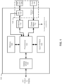
FIG. 1 is a block diagram of an example audio-visual device according to various embodiments. -
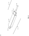
FIG. 2 depicts an audio-visual device connected to a cable via a connector according to various embodiments. -
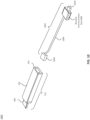
FIG. 3 depicts an audio-visual device unconnected from a cable via a connector according to various embodiments. -
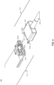
FIG. 4 depicts an audio-visual device unconnected from a cable via a connector according to various embodiments. -
FIG. 5 depicts connection ports of an audio-visual device according to various embodiments. -
FIG. 6 depicts an audio-visual device connected to a cable having external antenna components according to various embodiments. -
FIG. 7 depicts an audio-visual device connected to a cable having external antenna components according to various embodiments. -
FIG. 8 depicts an audio-visual device connected to a cable having external antenna components according to various embodiments. -
FIG. 9 is a flowchart depicting a method of detecting the presence of an external antenna according to various embodiments. -
FIGS. 10 and12 illustrate other example embodiments of a cable. -
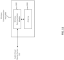
FIG. 11 is a block diagram of a wireless communication pod, according to some embodiments. - In the drawings, like reference numbers generally indicate identical or similar elements. Additionally, generally, the left-most digit(s) of a reference number identifies the drawing in which the reference number first appears.
- As discussed above, the present disclosure includes various embodiments that relate to devices, components, connectors, and/or cables that connect an audio-visual device (or other electrical device) to an external antenna.
FIG. 1 is a block diagram depicting an example audio-visual device 100 according to various embodiments. As shown inFIG. 1 ,display device 100 may include one ormore processors 102, adisplay driver 104,memory 106, and aninput interface 108. Additionally the audio-visual device may include anantenna module 110 and apower management module 112. - The
display driver 104 of the audio-visual device 100 may be configured to output audio-visual (A/V) output to, e.g., a display device such as a television, phone, tablet, computer, monitor, or the like. Thedisplay driver 104 may operate under the control ofprocessor 102 and may be configured to output A/V content via, e.g., a HDMI connection to the display (not shown). -
Memory 106 may comprise any appropriate memory storage device and may be configured to store a number of different kinds of information. For instance, in some embodiments,memory 106 may be configured to store a number of different streaming media applications for execution byprocessor 102 in either a compiled or un-compiled form. - The
interface 108 may be configured to accept user input from, for example, a remote control device (not shown). In some embodiments, theinterface 108 may include a wireless sensor (e.g., an infrared sensor) to communicate with a remote control device and to convey user input from the remote control device to theprocessor 102. - The
power management module 112 of audio-visual device 100 may be configured to receive electrical power from an external supply and to provide power to the various other components of the audio-visual device 100. For instance, as shown inFIG. 1 , thepower management module 112 receives electrical power fromport 126 and distributes the electrical power to the various components of the audio-visual device 100. Additionally, thepower management module 112 may be controlled byprocessor 102 to, for instance, adjust the amount of power to various components or to power on and off various components of audio-visual device 100. - The
antenna module 110 may contain one or more antennas that are configured to establish a wireless connection with a remote wireless signal source such as, a wireless internet router, a Bluetooth device, or a radio device, to name a few non-limiting examples. Theantenna module 110 may comprise one or more individual antenna integrated circuit components. In some embodiments, theantenna module 110 may include antenna elements directly printed on a printed circuit board of audio-visual device 100. - As shown in
FIG. 1 , the audio-visual device 100 may also include adevice connector 120. Thedevice connector 120 may include adetection circuit 122, anantenna port 124, and aport 126. As discussed above,port 126 may be configured to receive power from a source external to the audio-visual device 100. However,port 126 may also or instead be configured to receive data signals from a source external to the audio-visual device. Theport 126 can be configured to provide the received electrical power to thepower management module 112, where the electrical power may be distributed to the various portions of audio-visual device 100. In some instances, the power supply port could be any appropriate standard connection port such as a universal serial bus (USB) port, micro USB port, an AC adaptor plug, and a coaxial port, to name a few non-limiting examples. - The
device connector 120 may also include anantenna port 124 that is configured to connect the audio-visual device 100 to an external antenna that may be, in some embodiments, part of the same cable to whichport 126 is connected. According to various embodiments, the electrical cable that connects todevice connector 120 may comprise an HDMI cable, a USB cable, a micro USB cable, power cable, or any suitable cable that is capable of transmitting power and/or data signals. Furthermore, in some embodiments, one or more external antennas may be embedded in the cable along the length and/or diameter of the cable and be available for use by the audio-device 100 when they are connected to theantenna port 124. Additionally, thedevice connector 120 may include adetection mechanism 122 that detects the presence of an antenna connection in theantenna port 124. When an antenna connection is detected, the audio-visual device 100 may be configured to use one or more external antennas connected via theantenna port 124 to send and receive, e.g., wireless signals. In some embodiments, the audio-visual device 100 may be configured to use the one or more external antennas instead of aninternal antenna 110. Alternatively, in some embodiments, the audio-visual device 100 may be configured to use the one or more external antennas in conjunction withantenna module 110. Alternatively, in some embodiments, the audio-visual device 100 may not includeantenna module 110, instead relying on external antennas for wireless connectivity and communication. - In some embodiments, the
detection mechanism 122 may send a signal toprocessor 102 indicating the presence or non-presence of an antenna connection atantenna port 124. Theprocessor 102 may then electrically connect or disconnect theinternal antenna 110 from operation in favor of one or more external antennas (eg., antennas embedded in a cable connected to the antenna port) connected toantenna port 124 depending on the particular embodiment. However, in other embodiments, thedetection mechanism 122 may be implemented as a physical switch that connects or disconnects theantenna module 110 in favor of one or more external antennas connected toantenna port 124. -
FIG. 2 is an illustration of astreaming media device 200 according to various embodiments of the disclosure. As shown inFIG. 2 , thestreaming media device 200 may include an audio-visual device portion 212 and acable portion 214. In some embodiments, the audio-visual device portion 212 may be similar to audio-visual device 100 fromFIG. 1 . However,FIG. 2 should not be construed as so limiting. - The audio-
visual device portion 212 may itself comprise audio-visual device 202 and an A/V connector 208. WhileFIG. 2 depicts A/V connector 208 as an HDMI connector, other embodiments may utilize different A/V connectors such as component connectors, optical connectors, USB connectors, micro USB connectors, coaxial connectors, video graphics array (VGA) connectors, digital visual interface (DVI) connectors, to name several non-limiting examples. - The
cable portion 214 may itself comprise aconnector 204 and acable 206. Theconnector 204 may operate to connect to the audio-visual device portion 212 via device connection 210 (corresponding todevice connector 120 inFIG. 1 , for example). In some embodiments,device connection 210 may be a permanent connection and the audio-visual portion 212 and thecable portion 214 may form a single unitary body. However, in some embodiments thedevice connection 210 forms a detachable connection between the audio-visual portion 212 and thecable portion 214. - The
cable 206 ofcable portion 214 may connect the connector 210 (and by extension the audio-visual device portion 212) to a power supply, a data signal source, and/or one or more external antennas. In some embodiments, thecable 206 may comprise a modified standard cable (e.g., a USB or HDMI cable) that also includes antenna elements connected and extending along various points. In some embodiments, theconnector 204 may contain external antenna elements for connection to the audio-visual device portion 212. -
FIG. 3 illustrates a portion ofstreaming media device 300 similar to the streaming media system illustrated inFIG. 2 . As shown inFIG. 3 , thestreaming media device 300 contains an audio-visual device portion 212 and acable portion 214. In some embodiments, the audio-visual device portion 212 may be similar to audio-visual device 100 fromFIG. 1 . However,FIG. 3 should not be construed as so limiting. - The
streaming media device 300 inFIG. 3 is shown with the audio-visual device portion 212 detached from thecable portion 214. Each of the audio-visual portion 212 and thecable portion 214 has a corresponding connector portion. For instance, in the example ofFIG. 3 , the audio-visual device portion 212 has afemale connector portion 224 with ports for receiving the connectors from male themale connector portion 204 of thecable portion 214. - The
connector portion 224 of the audio-visual portion 212 is shown as havingantenna connection ports connection port 220. In some embodiments,connection port 220 may provide power, data signals, and/or some combination of power and data signals to the audio-visual portion. WhileFIG. 3 depictsconnection port 220 as a USB port, this is just one example of a possible kind of port that may be used. Any suitable port capable of carrying electrical power and/or data signals may be used. In some embodiments, theantenna connection ports antenna port 124 shown inFIG. 1 . Similarly, theUSB port 220 may correspond toport 126. - The
connector 204 of thecable portion 214 includesmale antenna connectors male connector 222.Male antenna connectors antenna ports connector portion 224. Additionally,male connector 222 is configured to mate withport 220 inconnector 224. - Each of the
antenna connectors cable 206. That is, theconnectors cable 206 along its length. However, in some embodiments, one or more external antennas may be part ofconnector 204. -
FIG. 4 illustrates a portion of an internal configuration ofstreaming media device 300 similar to the streaming media system illustrated inFIG. 3 with the cover of the audio-visual device portion 212 removed. As shown inFIG. 4 , thestreaming media device 300 contains an audio-visual device portion 212 and acable portion 214. In some embodiments, the audio-visual device portion 212 may be similar to audio-visual device 100 fromFIG. 1 . However,FIG. 4 should not be construed as so limiting. - As shown in
FIG. 4 , each of the audio-visual portion 212 and thecable portion 214 has a corresponding connector portion. For instance, the audio-visual device portion 212 has afemale connector portion 224 with ports for receiving the connectors from male themale connector portion 204 of thecable portion 214. - The
connector portion 224 of the audio-visual portion 212 is shown as havingantenna connection ports port 220. According to various embodiments,port 220 may comprise a USB port, a micro USB port, an HDMI port, a power port, or any suitable port that can transmit power, data signals, and/or some combination of power and data signals. In some embodiments, theantenna connection ports antenna port 124 shown inFIG. 1 . Similarly, theUSB port 220 may correspond toport 126. - The
connector 204 of thecable portion 214 includesmale antenna connectors male USB connector 222.Male antenna connectors antenna ports connector portion 224. Additionally,male connector 222 is configured to mate withport 220 inconnector 224. - Each of the
antenna connectors cable 206. However, in some embodiments, the external antenna may be part ofconnector 204. -
FIG. 4 also shows that the audio-visual device portion 212 contains aninternal antenna module 240. In various embodiments, whenconnectors ports visual device portion 212 may be configured to bypass theinternal antenna module 240 and use, instead, one or more external antennas that are connected viaconnectors visual device portion 212 may also be configured to use theinternal antenna module 240 in conjunction with one or more external antennas that are connected viaconnectors -
FIG. 5 depicts aconnector portion 224 of an audiovisual device 202 according to various embodiments of the disclosure. As shown, theconnector portion 224 may include aconnector port 220. According to variousembodiments connector port 220 may be a USB port, a micro USB port, and HDMI port, or any suitable port capable of carrying electrical power, data signals, and/or some combination of electrical power and data signals.Ports connectors ports -
FIG. 6 depicts a block diagram of astreaming media device 600 according to various embodiments of the disclosure. As shown inFIG. 6 , thestreaming media device 600 may include an audio-visual device portion 212 and acable portion 214 similar to the corresponding elements described with respect toFIG. 2 , above. However,FIG. 6 should not be construed as so limiting. - The audio-
visual device portion 212 may itself comprise audio-visual device 202 and an A/V connector 208 such as an HDMI connector, component connectors, optical connectors, USB connectors, micro USB connectors, coaxial connectors, video graphics array (VGA) connectors, digital visual interface (DVI) connectors, to name several non-limiting examples. - The
cable portion 214 may itself comprise aconnector 204 and acable 206. Theconnector 204 may operate to connect to the audio-visual device portion 212 viadevice connection 210. In some embodiments,device connection 210 may be a permanent connection and the audio-visual portion 212 and thecable portion 214 may form a single unitary body. However, in some embodiments thedevice connection 210 forms a detachable connection between the audio-visual portion 212 and thecable portion 214. - The
cable 206 ofcable portion 214 may connect the connector (and by extension the audio-visual device portion 212) to a power supply, a data signal source, some combination of power supply and a data source, and/or one or more external antennas. In some embodiments, thecable 206 may comprise a modified standard cable (e.g., a USB cable) that also includes antenna elements connected along various points. In some embodiments, theconnector 204 may contain external antenna elements for connection to the audio-visual device portion 212. - In some embodiments, the
cable portion 214 of thestreaming media device 600 also contains one or moreexternal antennas 602a and/or 602b. Specifically, in some embodiments, theexternal antennas cable 206 and may be connected to the audio-device portion 212 by, e.g., connectors such asconnectors external antennas antennas Frequency Wavelength Offset Distance d 2.4 GHz 12.5 cm 31.25 mm 3.6 GHz 8.33 cm 20.83 mm 4.9 GHz 6.12 cm 15.3 mm 5 GHz 6.0 cm 15 mm 5.9 GHz 5.08 cm 12.7 mm - For example, as shown in the above table, at a frequency of 3.4 GHz, the offset distance d may be around a quarter of the wavelength 12.5 cm, or 31.25 mm. At a frequency of 3.6 GHz, the offset distance d may be around a quarter of the wavelength 6.12 cm, or 15.3 mm. At a frequency of 4.9 GHz, the offset distance d may be around a quarter of the wavelength 6.12 cm, or 15.3 mm. At a frequency of 5 GHz, the offset distance d may be around a quarter of the wavelength 6.0 cm, or 15 mm. At a frequency of 5.9 GHz, the offset distance d may be around a quarter of the wavelength 5.08 cm, or 12.7 mm.
- In some embodiments, not shown in
FIG. 6 , external antennas may be contained withincable 206, and may extend along the internal diameter and/or length (to some extent) ofcable 206. -
FIG. 7 depicts a block diagram of astreaming media device 700 according to some embodiments of the disclosure. Streamingmedia device 700 is similar to the streaming media devices described with respect toFIGs. 2 and6 , above. That is, streaming media device may include an audio-visual device portion 212 and acable portion 214 similar to the corresponding elements described with respect toFIGs. 2 and6 , above. Thestreaming device 700 ofFIG. 7 , however, differs from other embodiments in that it hasexternal antennas connector portion 704. As shown inFIG. 7 , the connector portion may be shaped to allowexternal antennas FIG. 6 ,external antennas antennas -
FIG. 8 depicts a block diagram of astreaming media device 800 according to some embodiments of the disclosure. Streamingmedia device 800 is similar to the streaming media devices described with respect toFIGs. 2 ,6 , and7 , above. That is, streaming media device may include an audio-visual device portion 212 and acable portion 214 similar to the corresponding elements described with respect toFIGs. 2 ,6 , and7 , above. Thestreaming device 800 ofFIG. 8 , however, differs from other embodiments in that it hasexternal antennas connector portion 804. As shown inFIG. 8 , theconnector portion 804 may allowantennas FIGs. 6 and7 ,external antennas antennas - As noted above, the
device connector 120 may include detection circuitry (e.g., detection circuit 122) that is configured to detect whether an antenna connector is present atantenna port 124. This allows a user the flexibility of using, e.g., a standard connection cable (e.g., USB or HDMI) to connect to audio-visual device 100 or to use a modified cable (e.g., cable 204) that contains external antennas. When a standard cable is used, thedetection circuit 122 will not detect the presence of an antenna connector at the antenna port and the audio-visual device 100 can be configured to use its internal antenna module. However, when a modified cable with one or more antenna connectors is detected by thedetection circuit 122, then the audio-visual device 100 can be configured to use one or more external antennas either in conjunction with theinternal antenna module 110 or instead of theinternal antenna module 110.FIG. 9 is a flowchart illustrating thismethod 900 of detection. - As shown in
FIG. 9 ,method 900 begins at 902 with the connection of a cable (e.g. cable 206) to a port (e.g., port 220) of the audio-visual device portion 212. Upon detection of the presence of the cable, a detection circuit (e.g., detection circuit 122) may detect whether an antenna connection (e.g.,antenna connector ports processors 102. Additionally, in some embodiments, detecting the presence of an antenna connection may include detecting that one or more physical switches has been tripped by the insertion of an antenna connector (e.g.,connectors ports - If, at 904, the presence of an antenna connection is not detected, then the
method 900 proceeds to 906 and the audio-visual device 100 can be configured to conclude that the cable connection is a standard cable connection and the internal antenna module (e.g., antenna module 110) can be used. If, however, at 904 an antenna connection is detected, then themethod 900 may proceed to 908 and the audio-visual device 100 can be configured to use external antennas connected via the antenna connection. In some embodiments, the audio-visual device 100 may be configured to use one or more external antennas in conjunction with the internal antenna module (e.g., antenna module 110). However, the audio-visual device 100 may also be configured to use one or more external antennas instead of the internal antenna module in some embodiments. - Detection circuitry may be implemented using any combination of hardware and/or software configured to operate as shown in
FIG. 9 . - In the embodiment shown in
FIG. 1 ,processor 102 may be configured to enable and perform wireless connectivity and communication using theantenna module 110 and/or any external antennas according to any wireless communication standard, methodology or technology, including but not limited to any WIFI, cellular and/or short range communication standard, methodology or technology. In some embodiments, however, such wireless communication functionality is positioned external to the audio-visual device 100. - For example,
FIG. 10 illustrates an examplestreaming media device 1000 having audio-visual device portion 212 andcable portion 1002, according to some embodiments.FIG. 10 is generally similar toFIG. 2 . However, in the example ofFIG. 10 ,cable portion 1002 includes awireless communication pod 1008 proximate to or combined withconnector 1010, which may be a USB connector in some embodiments. - As shown in
FIG. 11 , in some embodiments, thewireless communication pod 1008 may include awireless communication module 1102 and an antenna 1104. Thewireless communication module 1102 may be configured to enable and perform wireless connectivity and communication using antenna 1104 (and/or any external antennas, as discussed herein with respect toFIG. 1 for example) according to any wireless communication standard, methodology or technology, including but not limited to any WIFI, cellular and/or short range communication standard, methodology or technology. - Referring back to
FIG. 10 , in some embodiments, the audio-visual device portion 212 maybe connected tocable portion 1002 viaport 210 andconnector 1004.Connector 208 may be inserted into an HDMI port of a television (or other display device), andUSB connector 1010 may be inserted into an USB port of the television. The embodiment ofFIG. 10 is advantageous because thewireless communication pod 1008 is generally not noticeable to users (that is, it is generally hidden from users), since it is combined with or part of theUSB connector 1010. But, the embodiment ofFIG. 10 may suffer from degraded wireless communication performance since thewireless communication pod 1008 is located close to the television (which may be the source of noise) when theUSB connector 1010 is connected to the television. -
FIG. 12 illustrates an examplestreaming media device 1200 having audio-visual device portion 212 andcable portion 1202, according to some embodiments.FIG. 12 is generally similar toFIGS. 2 and10 . However, in the example ofFIG. 12 ,cable portion 1202 includes awireless communication pod 1204 that is integrated withcable 1208 and located away from USB connector 1206 andconnector 1004. - The
wireless communication pod 1204 may be similar in structure and operation towireless communication pod 1008 shown inFIG. 11 . - In some embodiments, the audio-
visual device portion 212 may be connected tocable portion 1202 viaport 210 andconnector 1004.Connector 208 may be inserted into an HDMI port of a television (or other display device), and USB connector 1206 may be inserted into an USB port of the television. Becausewireless communication pod 1204 is located away from bothconnector 1004 and USB connector 1206, wireless performance is enhanced becausewireless communication pod 1204 is not located close to the television, which may be the source of noise, even whenconnectors 208 and 1206 are inserted into respective ports of the television. - In an embodiment,
wireless communication pod 1204 may be positioned incable 1208 equal distance, or substantially equal distance, fromconnector 1004 and USB connector 1206. In another embodiment,wireless communication pod 1204 may be offset fromconnector 1004 and USB connector 1206 incable 1208 by different distances, but sufficiently away from eitherconnector 1004,connector 208 or USB connector 1206 to reduce wireless communication interface due to noise from the television. - It is to be appreciated that the Detailed Description section, and not any other section, is intended to be used to interpret the claims. Other sections can set forth one or more but not all exemplary embodiments as contemplated by the inventor(s), and thus, are not intended to limit this disclosure or the appended claims in any way.
- While this disclosure describes exemplary embodiments for exemplary fields and applications, it should be understood that the disclosure is not limited thereto. Other embodiments and modifications thereto are possible, and are within the scope and spirit of this disclosure. For example, and without limiting the generality of this paragraph, embodiments are not limited to the software, hardware, firmware, and/or entities illustrated in the figures and/or described herein. Further, embodiments (whether or not explicitly described herein) have significant utility to fields and applications beyond the examples described herein.
- Embodiments have been described herein with the aid of functional building blocks illustrating the implementation of specified functions and relationships thereof. The boundaries of these functional building blocks have been arbitrarily defined herein for the convenience of the description. Alternate boundaries can be defined as long as the specified functions and relationships (or equivalents thereof) are appropriately performed. Also, alternative embodiments can perform functional blocks, steps, operations, methods, etc. using orderings different than those described herein.
- References herein to "one embodiment," "an embodiment," "an example embodiment," or similar phrases, indicate that the embodiment described can include a particular feature, structure, or characteristic, but every embodiment can not necessarily include the particular feature, structure, or characteristic. Moreover, such phrases are not necessarily referring to the same embodiment. Further, when a particular feature, structure, or characteristic is described in connection with an embodiment, it would be within the knowledge of persons skilled in the relevant art(s) to incorporate such feature, structure, or characteristic into other embodiments whether or not explicitly mentioned or described herein. Additionally, some embodiments can be described using the expression "coupled" and "connected" along with their derivatives. These terms are not necessarily intended as synonyms for each other. For example, some embodiments can be described using the terms "connected" and/or "coupled" to indicate that two or more elements are in direct physical or electrical contact with each other. The term "coupled," however, can also mean that two or more elements are not in direct contact with each other, but yet still co-operate or interact with each other.
- The breadth and scope of this disclosure should not be limited by any of the above-described exemplary embodiments, but should be defined only in accordance with the following claims and their equivalents.
- The following clauses, describing aspects of the invention, are part of the description
- 1. A device connector for connecting an electrical device to an external cable, the device connector comprising:
- a port configured to receive at least one of data and power from a source external to the audio-visual device;
- an antenna port configured to connect the audio-visual device to an external antenna; and
- a detection mechanism configured to detect the presence of an antenna connection at the antenna port.
- 2. The device connector of clause 1, wherein the antenna port comprises a coaxial antenna port.
- 3. The device connector of clause 1, further comprising:
an additional antenna port configured to connect the audio-visual device to an additional external antenna. - 4. The device connector of clause 1, wherein the port is a universal serial bus or HDMI port.
- 5. The device connector of clause 1, wherein, upon detecting the presence of the antenna connection, the detection mechanism is configured to bypass an internal antenna of the audio-visual device in favor of an antenna connected via the antenna connection.
- 6. The device connector of clause 1, wherein, upon detecting the presence of the antenna connection, the detection mechanism is configured to cause the audio-visual device to use an antenna connected via the antenna connection.
- 7. The device connector of clause 1, wherein the antenna connected via the antenna connection is used in parallel with an antenna internal to the audio-visual device.
- 8. A streaming media device comprising:
- an audio-visual device portion;
- a cable portion comprising a supply line and an antenna, wherein the supply line is configured to transport at least one of data and power; and
- a device connector configured to connect the cable portion to the audio-visual device portion.
- 9. The streaming media device of clause 8, wherein the audio-visual portion, the cable portion, and the device connector form a unitary body.
- 10. The streaming media device of clause 8, wherein the device connector is configured to detachably connect the cable portion to the audio-visual device portion.
- 11. The streaming media device of clause 10, wherein the device connector is further configured to detect the presence of an antenna connection.
- 12. The streaming media device of clause 11, wherein, upon detecting the presence of the antenna connection, the device connector is configured to bypass an internal antenna of the audio-visual device in favor of an antenna connected via the antenna connection.
- 13. The streaming media device of clause 11, wherein, upon detecting the presence of the antenna connection, the device connector is configured to cause the audio-visual device to use an antenna connected via the antenna connection.
- 14. The streaming media device of clause 8, wherein the cable portion comprises an additional antenna.
- 15. The streaming media device of clause 8, wherein the supply line comprises a universal serial bus.
- 16. The streaming media device of clause 8, wherein the audio-visual device portion comprises an internal antenna.
- 17. The streaming media device of clause 8, wherein the audio-visual device is configured to use the internal antenna in parallel with the antenna of the cable portion.
- 18. A cable for use with an electronic wireless communication device, the cable comprising:
- a supply line configured to carry at least one of power and data;
- an antenna; and
- a connection portion coupled to the supply line and the antenna, wherein the connection portion comprises an antenna connector that is electrically coupled to the antenna and a supply connector that is electrically coupled to the supply line.
- 19. The cable of clause 18, further comprising:
- an additional antenna; and
- wherein the connection portion further comprises an additional antenna connector that is electrically coupled to the additional antenna.
- 20. A media streaming device, comprising:
- an audio-visual device portion comprising a first connector coupled to a display device, and a second connector; and
- a cable portion comprising a first connector coupled to the display device, and a second connector coupled to the second connector of the audio-visual device portion, the cable portion further comprising a wireless communication pod, wherein the wireless communication pod is positioned in the cable portion away from the first and second connectors of the cable portion.
Claims (15)
- A device connector for connecting an audio-visual device to an external cable, the device connector comprising:a port configured to receive power from a source external to the audio-visual device;an antenna port configured to connect the audio-visual device to an external antenna via at least one antenna connector of the external cable, and wherein the port is further configured to receive the power from a power connector of the external cable and wherein the external antenna comprises a first external antenna and a second external antenna and is integrated in the external cable; anda detection mechanism, connected to the antenna port, configured to:detect an antenna connection by the external antenna at the antenna port;connect to an internal antenna of the audio-visual device; andtransmit a signal to the audio-visual device upon detecting the antenna connection, wherein the signal is configured to cause the audio-visual device to utilize one of the external antenna or the internal antenna.
- The device connector of claim 1, wherein the antenna port comprises a coaxial antenna port.
- The device connector of claim 1, further comprising:
an additional antenna port configured to connect the audio-visual device to an additional external antenna. - The device connector of claim 1, wherein the port is a universal serial bus or HDMI port.
- The device connector of claim 1, wherein the signal is configured to cause the audio-visual device to bypass the internal antenna of the audio-visual device to connect to the external antenna connected via the antenna connection.
- The device connector of claim 1, wherein the signal is configured to cause the audio-visual device to use the external antenna connected via the antenna connection.
- The device connector of claim 1, wherein the external antenna connected via the antenna connection is used in parallel with the internal antenna of the audio-visual device.
- The device connector of claim 1, wherein the port is further configured to connect to a power management module of the audio-visual device.
- The device connector of claim 1, wherein the device connector is shaped to allow the first external antenna and the second external antenna to be linearly offset from each other by a predetermined distance.
- The device connector of claim 9, wherein the external antenna is configured to transmit a carrier signal with a predetermined wavelength and the predetermined distance is based on a fraction of the predetermined wavelength.
- The device connector of claim 10, wherein the predetermined wavelength is 12.5 cm and the predetermined distance is 31.25 millimeters.
- A streaming media device comprising:an audio-visual device portion comprising an internal antenna;a cable portion comprising a supply line and an antenna, wherein the supply line is configured to transport at least one of data and power; anda device connector configured to connect the cable portion to the audio-visual device portion, wherein the device connector comprises:a port configured to receive power from a source external to the audio-visual device;an antenna port configured to connect the audio-visual device to an external antenna via at least one antenna connector of an external cable, and wherein the port is further configured to receive the power from a power connector of the external cable and wherein the external antenna comprises a first external antenna and a second external antenna and is integrated in the external cable; anda detection mechanism, connected to the antenna port, configured to:detect an antenna connection by the external antenna at the antenna port;connect to the internal antenna of the audio-visual device; andtransmit a signal to the audio-visual device upon detecting the antenna connection, wherein the signal is configured to cause the audio-visual device to utilize one of the external antenna or the internal antenna.
- The streaming media device of claim 12, wherein the audio-visual portion, the cable portion, and the device connector form a unitary body.
- The streaming media device of claim 12, wherein the device connector is configured to detachably connect the cable portion to the audio-visual device portion.
- A cable for use with an streaming media device, the cable comprising:a supply line configured to carry at least one of power and data;a first antenna;a second antenna, wherein the first antenna and the second antenna are linearly offset from each other within the cable; anda connection portion coupled to the supply line, the first antenna, and the second antenna, wherein the connection portion comprises an antenna connector that is electrically coupled to the antenna and a supply connector that is electrically coupled to the supply line.
Applications Claiming Priority (3)
| Application Number | Priority Date | Filing Date | Title |
|---|---|---|---|
| US15/455,561 US10971866B2 (en) | 2017-03-10 | 2017-03-10 | Connector device with antenna connection |
| EP18763254.2A EP3593540B1 (en) | 2017-03-10 | 2018-03-09 | Connector device with antenna connection |
| PCT/US2018/021705 WO2018165527A1 (en) | 2017-03-10 | 2018-03-09 | Connector device with antenna connection |
Related Parent Applications (1)
| Application Number | Title | Priority Date | Filing Date |
|---|---|---|---|
| EP18763254.2A Division EP3593540B1 (en) | 2017-03-10 | 2018-03-09 | Connector device with antenna connection |
Publications (1)
| Publication Number | Publication Date |
|---|---|
| EP4203187A1 true EP4203187A1 (en) | 2023-06-28 |
Family
ID=63445198
Family Applications (2)
| Application Number | Title | Priority Date | Filing Date |
|---|---|---|---|
| EP23151313.6A Pending EP4203187A1 (en) | 2017-03-10 | 2018-03-09 | Connector device with antenna connection |
| EP18763254.2A Active EP3593540B1 (en) | 2017-03-10 | 2018-03-09 | Connector device with antenna connection |
Family Applications After (1)
| Application Number | Title | Priority Date | Filing Date |
|---|---|---|---|
| EP18763254.2A Active EP3593540B1 (en) | 2017-03-10 | 2018-03-09 | Connector device with antenna connection |
Country Status (3)
| Country | Link |
|---|---|
| US (3) | US10971866B2 (en) |
| EP (2) | EP4203187A1 (en) |
| WO (1) | WO2018165527A1 (en) |
Families Citing this family (1)
| Publication number | Priority date | Publication date | Assignee | Title |
|---|---|---|---|---|
| US10971866B2 (en) | 2017-03-10 | 2021-04-06 | Roku, Inc. | Connector device with antenna connection |
Citations (2)
| Publication number | Priority date | Publication date | Assignee | Title |
|---|---|---|---|---|
| US20080084356A1 (en) * | 2006-10-06 | 2008-04-10 | Sony Ericsson Mobile Communications Ab | Antenna for portable communication device |
| WO2016051091A1 (en) * | 2014-09-30 | 2016-04-07 | Orange | Mobile radio antenna for a small receiver |
Family Cites Families (16)
| Publication number | Priority date | Publication date | Assignee | Title |
|---|---|---|---|---|
| US6016432A (en) * | 1993-03-04 | 2000-01-18 | Telefonaktiebolaget L/M Ericsson (Publ) | Electronic metering equipment system |
| US5488649A (en) * | 1994-05-06 | 1996-01-30 | Motorola, Inc. | Method for validating a communication link |
| FI107485B (en) * | 1996-04-17 | 2001-08-15 | Nokia Mobile Phones Ltd | Diversity method, radio receiver and radio system |
| US5961337A (en) * | 1996-11-27 | 1999-10-05 | Norand Corporation | Universal charging and data communication apparatus |
| KR100437087B1 (en) * | 2001-10-29 | 2004-06-23 | 삼성전자주식회사 | Method for controlling operation of mobile terminal capable of high data rate service |
| KR100436665B1 (en) * | 2001-11-27 | 2004-06-22 | 삼성전자주식회사 | Interface connection cable having antenna and antenna diversity fabrication in mobile communication terminal thereof |
| US20040187156A1 (en) * | 2003-01-08 | 2004-09-23 | Stephen Palm | Transporting home networking frame-based communication signals over coaxial cables |
| US20080039160A1 (en) * | 2006-07-21 | 2008-02-14 | Homer Steven S | Wireless communications interface for a portable electronic device |
| US20080233869A1 (en) * | 2007-03-19 | 2008-09-25 | Thomas Baker | Method and system for a single-chip fm tuning system for transmit and receive antennas |
| EP2453278A3 (en) * | 2010-11-12 | 2012-08-29 | Research In Motion Limited | Device with magnetically coupled data connector for electrical and optical data circuits |
| US9286854B2 (en) | 2011-10-31 | 2016-03-15 | Roku, Inc. | Multi-interface streaming media system |
| CN102780793B (en) * | 2012-07-20 | 2016-02-10 | 惠州Tcl移动通信有限公司 | The mobile terminal of compatible built-in aerial and external antenna function |
| AU2016246595A1 (en) * | 2015-04-06 | 2017-10-26 | Nextivity, Inc. | Integrated power supply and antenna for repeater |
| US20180241420A1 (en) * | 2015-11-11 | 2018-08-23 | Mitsubishi Electric Corporation | In-vehicle wireless communication device |
| US9887497B1 (en) * | 2016-06-10 | 2018-02-06 | Amazon Technologies, Inc. | Device connector with reduced electromagnetic noise |
| US10971866B2 (en) * | 2017-03-10 | 2021-04-06 | Roku, Inc. | Connector device with antenna connection |
-
2017
- 2017-03-10 US US15/455,561 patent/US10971866B2/en active Active
-
2018
- 2018-03-09 EP EP23151313.6A patent/EP4203187A1/en active Pending
- 2018-03-09 EP EP18763254.2A patent/EP3593540B1/en active Active
- 2018-03-09 WO PCT/US2018/021705 patent/WO2018165527A1/en not_active Ceased
-
2021
- 2021-04-06 US US17/223,936 patent/US11923606B2/en active Active
-
2024
- 2024-01-26 US US18/424,328 patent/US12308515B2/en active Active
Patent Citations (3)
| Publication number | Priority date | Publication date | Assignee | Title |
|---|---|---|---|---|
| US20080084356A1 (en) * | 2006-10-06 | 2008-04-10 | Sony Ericsson Mobile Communications Ab | Antenna for portable communication device |
| WO2016051091A1 (en) * | 2014-09-30 | 2016-04-07 | Orange | Mobile radio antenna for a small receiver |
| US20170214118A1 (en) * | 2014-09-30 | 2017-07-27 | Orange | Mobile radio antenna for a small receiver |
Also Published As
| Publication number | Publication date |
|---|---|
| EP3593540A1 (en) | 2020-01-15 |
| US10971866B2 (en) | 2021-04-06 |
| US20240170837A1 (en) | 2024-05-23 |
| US20180262280A1 (en) | 2018-09-13 |
| WO2018165527A1 (en) | 2018-09-13 |
| US20210257791A1 (en) | 2021-08-19 |
| EP3593540B1 (en) | 2023-01-18 |
| EP3593540A4 (en) | 2020-11-11 |
| US12308515B2 (en) | 2025-05-20 |
| US11923606B2 (en) | 2024-03-05 |
Similar Documents
| Publication | Publication Date | Title |
|---|---|---|
| EP2819311B1 (en) | Input/output apparatus | |
| EP2206205B1 (en) | Universal serial bus connector with antenna capabilities | |
| US7727029B2 (en) | Connector arrangement having multiple independent connectors | |
| US20070197052A1 (en) | Composite simple plug | |
| US11962115B2 (en) | Expansion device with power and data connections | |
| EP2693646B1 (en) | I/o device | |
| CN103297887A (en) | Earphone, circuit structure of mobile device and mobile device | |
| US8113877B2 (en) | Connector for connecting external antenna | |
| US12308515B2 (en) | Connector device with antenna connection | |
| US20130323951A1 (en) | Adaptor for connecting connectors with different interfaces | |
| US11398690B2 (en) | Wireless transmission device | |
| EP2976873B1 (en) | Interconnect assembly | |
| CN112510361B (en) | Passive Antennas and Antenna Systems | |
| US20140286252A1 (en) | Wireless transmission module having multi-transmission channels | |
| CN220528178U (en) | Two-way switching circuit and electronic equipment based on female seat | |
| CN219162678U (en) | multi-function display device | |
| TW200826696A (en) | Digital signal processing system and complex signal connector thereof | |
| CN201123084Y (en) | Multimedia mobile phone with mobile television receiver communication transmission interface | |
| KR100771591B1 (en) | Mobile communication terminal system | |
| US20090150585A1 (en) | Connecting an integrated antenna in a flat panel display to a desktop computer | |
| CN217641872U (en) | Male head, female head, interface system, electronic equipment and data line | |
| US20170214118A1 (en) | Mobile radio antenna for a small receiver | |
| US20120279836A1 (en) | Switch arrangement, system & device | |
| CN101212112A (en) | Video signal switching device |
Legal Events
| Date | Code | Title | Description |
|---|---|---|---|
| PUAI | Public reference made under article 153(3) epc to a published international application that has entered the european phase |
Free format text: ORIGINAL CODE: 0009012 |
|
| STAA | Information on the status of an ep patent application or granted ep patent |
Free format text: STATUS: THE APPLICATION HAS BEEN PUBLISHED |
|
| AC | Divisional application: reference to earlier application |
Ref document number: 3593540 Country of ref document: EP Kind code of ref document: P |
|
| AK | Designated contracting states |
Kind code of ref document: A1 Designated state(s): AL AT BE BG CH CY CZ DE DK EE ES FI FR GB GR HR HU IE IS IT LI LT LU LV MC MK MT NL NO PL PT RO RS SE SI SK SM TR |
|
| STAA | Information on the status of an ep patent application or granted ep patent |
Free format text: STATUS: REQUEST FOR EXAMINATION WAS MADE |
|
| 17P | Request for examination filed |
Effective date: 20231228 |
|
| RBV | Designated contracting states (corrected) |
Designated state(s): AL AT BE BG CH CY CZ DE DK EE ES FI FR GB GR HR HU IE IS IT LI LT LU LV MC MK MT NL NO PL PT RO RS SE SI SK SM TR |
|
| STAA | Information on the status of an ep patent application or granted ep patent |
Free format text: STATUS: EXAMINATION IS IN PROGRESS |
|
| 17Q | First examination report despatched |
Effective date: 20250401 |
|
| RAP3 | Party data changed (applicant data changed or rights of an application transferred) |
Owner name: ROKU, INC. |