EP4203174A1 - Secondary battery - Google Patents
Secondary battery Download PDFInfo
- Publication number
- EP4203174A1 EP4203174A1 EP22213565.9A EP22213565A EP4203174A1 EP 4203174 A1 EP4203174 A1 EP 4203174A1 EP 22213565 A EP22213565 A EP 22213565A EP 4203174 A1 EP4203174 A1 EP 4203174A1
- Authority
- EP
- European Patent Office
- Prior art keywords
- current collecting
- electrode body
- lid
- positive electrode
- liquid injection
- Prior art date
- Legal status (The legal status is an assumption and is not a legal conclusion. Google has not performed a legal analysis and makes no representation as to the accuracy of the status listed.)
- Pending
Links
Images


Classifications
-
- H—ELECTRICITY
- H01—ELECTRIC ELEMENTS
- H01M—PROCESSES OR MEANS, e.g. BATTERIES, FOR THE DIRECT CONVERSION OF CHEMICAL ENERGY INTO ELECTRICAL ENERGY
- H01M10/00—Secondary cells; Manufacture thereof
- H01M10/05—Accumulators with non-aqueous electrolyte
- H01M10/058—Construction or manufacture
-
- H—ELECTRICITY
- H01—ELECTRIC ELEMENTS
- H01M—PROCESSES OR MEANS, e.g. BATTERIES, FOR THE DIRECT CONVERSION OF CHEMICAL ENERGY INTO ELECTRICAL ENERGY
- H01M50/00—Constructional details or processes of manufacture of the non-active parts of electrochemical cells other than fuel cells, e.g. hybrid cells
- H01M50/60—Arrangements or processes for filling or topping-up with liquids; Arrangements or processes for draining liquids from casings
- H01M50/609—Arrangements or processes for filling with liquid, e.g. electrolytes
- H01M50/627—Filling ports
-
- H—ELECTRICITY
- H01—ELECTRIC ELEMENTS
- H01M—PROCESSES OR MEANS, e.g. BATTERIES, FOR THE DIRECT CONVERSION OF CHEMICAL ENERGY INTO ELECTRICAL ENERGY
- H01M50/00—Constructional details or processes of manufacture of the non-active parts of electrochemical cells other than fuel cells, e.g. hybrid cells
- H01M50/50—Current conducting connections for cells or batteries
- H01M50/572—Means for preventing undesired use or discharge
- H01M50/584—Means for preventing undesired use or discharge for preventing incorrect connections inside or outside the batteries
- H01M50/59—Means for preventing undesired use or discharge for preventing incorrect connections inside or outside the batteries characterised by the protection means
-
- H—ELECTRICITY
- H01—ELECTRIC ELEMENTS
- H01M—PROCESSES OR MEANS, e.g. BATTERIES, FOR THE DIRECT CONVERSION OF CHEMICAL ENERGY INTO ELECTRICAL ENERGY
- H01M10/00—Secondary cells; Manufacture thereof
- H01M10/04—Construction or manufacture in general
- H01M10/0413—Large-sized flat cells or batteries for motive or stationary systems with plate-like electrodes
-
- H—ELECTRICITY
- H01—ELECTRIC ELEMENTS
- H01M—PROCESSES OR MEANS, e.g. BATTERIES, FOR THE DIRECT CONVERSION OF CHEMICAL ENERGY INTO ELECTRICAL ENERGY
- H01M10/00—Secondary cells; Manufacture thereof
- H01M10/05—Accumulators with non-aqueous electrolyte
- H01M10/052—Li-accumulators
- H01M10/0525—Rocking-chair batteries, i.e. batteries with lithium insertion or intercalation in both electrodes; Lithium-ion batteries
-
- H—ELECTRICITY
- H01—ELECTRIC ELEMENTS
- H01M—PROCESSES OR MEANS, e.g. BATTERIES, FOR THE DIRECT CONVERSION OF CHEMICAL ENERGY INTO ELECTRICAL ENERGY
- H01M10/00—Secondary cells; Manufacture thereof
- H01M10/42—Methods or arrangements for servicing or maintenance of secondary cells or secondary half-cells
- H01M10/4235—Safety or regulating additives or arrangements in electrodes, separators or electrolyte
-
- H—ELECTRICITY
- H01—ELECTRIC ELEMENTS
- H01M—PROCESSES OR MEANS, e.g. BATTERIES, FOR THE DIRECT CONVERSION OF CHEMICAL ENERGY INTO ELECTRICAL ENERGY
- H01M50/00—Constructional details or processes of manufacture of the non-active parts of electrochemical cells other than fuel cells, e.g. hybrid cells
- H01M50/10—Primary casings; Jackets or wrappings
- H01M50/102—Primary casings; Jackets or wrappings characterised by their shape or physical structure
- H01M50/103—Primary casings; Jackets or wrappings characterised by their shape or physical structure prismatic or rectangular
-
- H—ELECTRICITY
- H01—ELECTRIC ELEMENTS
- H01M—PROCESSES OR MEANS, e.g. BATTERIES, FOR THE DIRECT CONVERSION OF CHEMICAL ENERGY INTO ELECTRICAL ENERGY
- H01M50/00—Constructional details or processes of manufacture of the non-active parts of electrochemical cells other than fuel cells, e.g. hybrid cells
- H01M50/10—Primary casings; Jackets or wrappings
- H01M50/147—Lids or covers
- H01M50/148—Lids or covers characterised by their shape
- H01M50/15—Lids or covers characterised by their shape for prismatic or rectangular cells
-
- H—ELECTRICITY
- H01—ELECTRIC ELEMENTS
- H01M—PROCESSES OR MEANS, e.g. BATTERIES, FOR THE DIRECT CONVERSION OF CHEMICAL ENERGY INTO ELECTRICAL ENERGY
- H01M50/00—Constructional details or processes of manufacture of the non-active parts of electrochemical cells other than fuel cells, e.g. hybrid cells
- H01M50/40—Separators; Membranes; Diaphragms; Spacing elements inside cells
- H01M50/471—Spacing elements inside cells other than separators, membranes or diaphragms; Manufacturing processes thereof
- H01M50/474—Spacing elements inside cells other than separators, membranes or diaphragms; Manufacturing processes thereof characterised by their position inside the cells
-
- H—ELECTRICITY
- H01—ELECTRIC ELEMENTS
- H01M—PROCESSES OR MEANS, e.g. BATTERIES, FOR THE DIRECT CONVERSION OF CHEMICAL ENERGY INTO ELECTRICAL ENERGY
- H01M50/00—Constructional details or processes of manufacture of the non-active parts of electrochemical cells other than fuel cells, e.g. hybrid cells
- H01M50/40—Separators; Membranes; Diaphragms; Spacing elements inside cells
- H01M50/471—Spacing elements inside cells other than separators, membranes or diaphragms; Manufacturing processes thereof
- H01M50/477—Spacing elements inside cells other than separators, membranes or diaphragms; Manufacturing processes thereof characterised by their shape
-
- H—ELECTRICITY
- H01—ELECTRIC ELEMENTS
- H01M—PROCESSES OR MEANS, e.g. BATTERIES, FOR THE DIRECT CONVERSION OF CHEMICAL ENERGY INTO ELECTRICAL ENERGY
- H01M50/00—Constructional details or processes of manufacture of the non-active parts of electrochemical cells other than fuel cells, e.g. hybrid cells
- H01M50/50—Current conducting connections for cells or batteries
- H01M50/543—Terminals
-
- H—ELECTRICITY
- H01—ELECTRIC ELEMENTS
- H01M—PROCESSES OR MEANS, e.g. BATTERIES, FOR THE DIRECT CONVERSION OF CHEMICAL ENERGY INTO ELECTRICAL ENERGY
- H01M50/00—Constructional details or processes of manufacture of the non-active parts of electrochemical cells other than fuel cells, e.g. hybrid cells
- H01M50/50—Current conducting connections for cells or batteries
- H01M50/572—Means for preventing undesired use or discharge
- H01M50/584—Means for preventing undesired use or discharge for preventing incorrect connections inside or outside the batteries
- H01M50/586—Means for preventing undesired use or discharge for preventing incorrect connections inside or outside the batteries inside the batteries, e.g. incorrect connections of electrodes
-
- H—ELECTRICITY
- H01—ELECTRIC ELEMENTS
- H01M—PROCESSES OR MEANS, e.g. BATTERIES, FOR THE DIRECT CONVERSION OF CHEMICAL ENERGY INTO ELECTRICAL ENERGY
- H01M50/00—Constructional details or processes of manufacture of the non-active parts of electrochemical cells other than fuel cells, e.g. hybrid cells
- H01M50/50—Current conducting connections for cells or batteries
- H01M50/572—Means for preventing undesired use or discharge
- H01M50/584—Means for preventing undesired use or discharge for preventing incorrect connections inside or outside the batteries
- H01M50/59—Means for preventing undesired use or discharge for preventing incorrect connections inside or outside the batteries characterised by the protection means
- H01M50/593—Spacers; Insulating plates
-
- H—ELECTRICITY
- H01—ELECTRIC ELEMENTS
- H01M—PROCESSES OR MEANS, e.g. BATTERIES, FOR THE DIRECT CONVERSION OF CHEMICAL ENERGY INTO ELECTRICAL ENERGY
- H01M50/00—Constructional details or processes of manufacture of the non-active parts of electrochemical cells other than fuel cells, e.g. hybrid cells
- H01M50/60—Arrangements or processes for filling or topping-up with liquids; Arrangements or processes for draining liquids from casings
- H01M50/609—Arrangements or processes for filling with liquid, e.g. electrolytes
-
- Y—GENERAL TAGGING OF NEW TECHNOLOGICAL DEVELOPMENTS; GENERAL TAGGING OF CROSS-SECTIONAL TECHNOLOGIES SPANNING OVER SEVERAL SECTIONS OF THE IPC; TECHNICAL SUBJECTS COVERED BY FORMER USPC CROSS-REFERENCE ART COLLECTIONS [XRACs] AND DIGESTS
- Y02—TECHNOLOGIES OR APPLICATIONS FOR MITIGATION OR ADAPTATION AGAINST CLIMATE CHANGE
- Y02E—REDUCTION OF GREENHOUSE GAS [GHG] EMISSIONS, RELATED TO ENERGY GENERATION, TRANSMISSION OR DISTRIBUTION
- Y02E60/00—Enabling technologies; Technologies with a potential or indirect contribution to GHG emissions mitigation
- Y02E60/10—Energy storage using batteries
Definitions
- the present disclosure relates to a secondary battery.
- Japanese Laid-open Patent Publication No. 2019-129129 discloses a storage device including an electrode body including a first electrode plate, a second electrode plate, and a separator disposed between the first electrode plate and the second electrode plate, an exterior body that houses the electrode body, a lid that closes an opening of the exterior body, and an electrode terminal that is electrically connected to the electrode body and has a portion exposed to outside of the exterior body through the lid.
- the lid of the storage device disclosed in Japanese Laid-open Patent Publication No. 2019-129129 has a liquid injection hole through which an electrolyte is injected into the exterior body.
- a cylindrical boy disposed between an outer surface of the lid and the electrode body and extending from the lid toward the electrode body to surround an opening of the liquid injection hole in a surface of the lid located closer to the electrode body is provided.
- a shielding portion provided between the liquid injection hole and the electrode body is connected to the cylindrical body.
- the present inventors desire to suppress damage of an electrode body housed in a battery case.
- a secondary battery disclosed herein includes an electrode body, a case body having an opening that houses the electrode body, and a lid mounted at the opening of the case body.
- the lid includes a liquid injection port through which an electrolyte is injected, an insulation member mounted on an inner surface of the lid, and an insulation holder that is mounted on the insulation member and at least a portion of which is opposed to the liquid injection port at an interval.
- the insulation holder includes a liquid receiving portion disposed in a position opposed to the liquid injection port, and an electrode body protective portion disposed in a position closer to the electrode body than a position of the liquid receiving portion.
- a momentum of the electrolyte in injecting the electrolyte is weakened, so that damage of the electrode body is prevented.
- the electrode body protective portion may be formed in a flat plate-like shape.
- the insulation holder may have a hole through which the electrolyte injected from the liquid injection port in a position shifted from the liquid injection port.
- the insulation holder may include a support portion extending from the electrode body protective portion toward the lid.
- a partition portion that partitions a tab may extend from the liquid receiving portion toward the electrode body.
- a term "secondary battery” refers to overall storage devices in which charge carriers move between a pair of electrodes (a positive electrode and a negative electrode) via an electrolyte and thus a charging and discharging reaction occurs.
- Such secondary batteries include not only so-called storage batteries, such as a lithium-ion secondary battery, a nickel hydrogen battery, a nickel cadmium battery, or the like, but also capacitors, such as an electric double-layered capacitor or the like.
- a lithium-ion secondary battery, among the above-described secondary batteries, is a target will be described below.
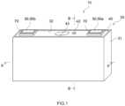
- FIG. 1 is a perspective view of a secondary battery 10.
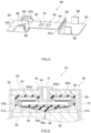
- FIG. 2 is a cross-sectional view taken along a line II-II of FIG. 1 .
- FIG. 2 schematically illustrates a partial cross-sectional view of a state where an inside of the secondary battery 10 is exposed along a broad width surface on one side of a battery case 30 having an approximately rectangular parallelepiped shape.
- FIG. 3 is a cross-sectional view taken along a line III-III of FIG. 1 .
- FIG. 3 schematically illustrates a partial cross-sectional view of a state where the inside of the secondary battery 10 is exposed along a narrow width surface on one side of the battery case 30 having an approximately rectangular parallelepiped shape. As illustrated in FIG.
- the secondary battery 10 includes an electrode body 20 (see FIG. 2 ) and the battery case 30.
- the battery case 30 is formed of a case body 31 and a lid 40.
- the secondary battery 10 includes terminals 50 and current collecting terminals 60.
- the terminals 50 include a positive electrode terminal 50a and a negative electrode terminal 50b.
- the current collecting terminals 60 include a positive electrode current collecting terminal 60a and a negative electrode current collecting terminal 60b.
- the electrode body 20 is connected to the positive electrode terminal 50a via the positive electrode current collecting terminal 60a.
- the electrode body 20 is connected to the negative electrode terminal 50b via the negative electrode current collecting terminal 60b.
- the electrode body 20 is a power generation element of the secondary battery 10.
- the electrode body 20 includes a positive electrode sheet 21 as a positive electrode element, a negative electrode sheet 22 as a negative electrode element, and a sheet-like separator 23.
- the separator 23 is disposed between the positive electrode sheet 21 and the negative electrode sheet 22.
- the positive electrode sheets 21, the negative electrode sheets 22, and the separators 23 are stacked.
- the electrode body 20 according to this embodiment has a stacked structure in which the positive electrode sheet 21 and the negative electrode sheet 22 each of which has been formed into a preset shape are stacked with the separator 23 interposed therebetween.
- the positive electrode sheet 21 includes a rectangular positive electrode current collecting foil, a positive electrode active material layer formed on both sides of the positive electrode current collecting foil, and a positive electrode current collecting tab 21a that protrudes from the positive electrode active material layer.
- the positive electrode current collecting foil is, for example, an aluminum foil.
- the positive electrode active material layer includes a positive electrode active material.
- the positive electrode active material is a material, such as a lithium transition metal compound material, that emits lithium ions during charging and absorbs lithium ions during discharging.
- various other materials than the lithium transition metal compound material have been proposed for positive electrode active materials, and there is no particular limitation on the positive electrode active material used herein.
- the positive electrode current collecting tab 21a is a portion of the positive electrode current collecting foil and protrudes from the positive electrode active material layer. Herein, the positive electrode current collecting tab 21a protrudes upward from the positive electrode active material layer. The positive electrode active material layer is not formed in the positive electrode sheet 21.
- the negative electrode sheet 22 includes a rectangular negative electrode current collecting foil, a negative electrode active material layer formed on both sides of the negative electrode current collecting foil, and a negative electrode current collecting tab 22a that protrudes from the negative electrode active material layer.
- the negative electrode current collecting foil is, for example, a copper foil.
- the negative electrode active material layer includes a negative electrode active material.
- the negative electrode active material is a material, such as natural graphite, that absorbs lithium ions during charging and emits lithium ions that have been absorbed during charging during discharging.
- various other materials than the natural graphite have been proposed for negative electrode active materials, and there is no particular limitation on the negative electrode active material used herein.
- the negative electrode current collecting tab 22a is a portion of the negative electrode current collecting foil and protrudes from the negative electrode active material layer. Herein, the negative electrode current collecting tab 22a protrudes upward from the negative electrode active material layer. The negative electrode active material layer is not formed in the negative electrode current collecting tab 22a.
- the separator 23 is, for example, a porous resin sheet which has a required heat resistance and through which an electrolyte can pass.
- the separator 23 is formed of a porous sheet (for example, a film, a nonwoven fabric, or the like) formed of a resin, such as, for example, polyethylene (PE), polypropylene (PP), polyester, cellulose, polyamide, or the like.
- the electrode body 20 is produced by stacking the positive electrode sheets 21 and the negative electrode sheets 22 with the separators 23 interposed therebetween.
- Each of the plurality of positive electrode current collecting tabs 21a and the plurality of negative electrode current collecting tabs 22a is connected to a corresponding one of the positive electrode current collecting terminal 60a and the negative electrode current collecting terminal 60b, which will be described later, in a stacked state.
- the battery case 30 is formed of the case body 31 having a space therein and the lid 40, as illustrated in FIG. 2 .
- the case body 31 is a case with a portion opened.
- the case body 31 has an opening 32 that houses the electrode body 20.
- the lid 40 is mounted at the opening 32 of the case body 31.
- the electrode body 20 is housed in the battery case 30.
- two electrode bodies 20 are housed in the battery case 30.
- an electrolyte is housed with the electrode body 20.
- the electrolyte for example, a nonaqueous electrolyte obtained by dissolving a supporting salt into a non-aqueous solvent can be used.
- non-aqueous solvent examples include a carbonate base solvent, such as ethylene carbonate, dimethyl carbonate, ethyl methyl carbonate, or the like.
- the supporting salt examples include a fluorine-containing lithium salt, such as LiPF 6 or the like.
- the battery case 30 has a rectangular parallelepiped shape (see FIG. 1 ).
- a material forming the battery case 30 can be formed of, for example, aluminum or an aluminum alloy mainly composed of aluminum.
- the lid 40 is a plate-like member provided to the opening 32 of the case body 31.
- the lid 40 has a rectangular shape that is long in a predetermined direction (herein, a rectangle). With the lid 40 mounted at the opening 32, a peripheral portion of the lid 40 is joined to an edge of the opening 32 of the case body 31.
- the above-described joining may be realized, for example, by continuous welding without any gap.
- the case body 31 and the lid 40 can be joined to each other, for example, by laser welding.
- the lid 40 can be formed of, for example, aluminum or an aluminum alloy mainly composed of aluminum.
- a gas exhaust valve 43 is provided in the lid 40.
- the gas exhaust valve 43 is a thin portion configured to be broken to discharge gas in the battery case 30 to outside of the battery case 30 when an internal pressure of the secondary battery 10 is a predetermined value or more.
- the lid 40 includes a liquid injection port 41, an insulation member 80, and an insulation holder 90.
- the terminals 50 and the current collecting terminals 60 are mounted on the lid 40.
- the terminals 50 include the positive electrode terminal 50a and the negative electrode terminal 50b.
- the current collecting terminals 60 include the positive electrode current collecting terminal 60a and the negative electrode current collecting terminal 60b.
- Mounting holes 45 are formed in the lid 40. The terminals 50 are mounted on the lid 40 in a state where the terminals 50 are inserted in the mounting holes 45.
- the terminal 50 includes a head portion 51, a cylindrical portion 52, and a caulked portion 53.
- the head portion 51 is disposed outside of the battery case 30.
- the head portion 51 is an approximately flat plate-like portion larger than the mounting hole 45 and is disposed along an outer surface of the lid 40.
- the cylindrical portion 52 is inserted in the mounting hole 45 via an external insulation member 70.
- the cylindrical portion 52 protrudes downward from a central portion of the head portion 51.
- the cylindrical portion 52 is extending in an up-down direction.
- the caulked portion 53 is caulked to a first current collecting terminal 61. In other words, the caulked portion 53 is caulked to the lid 40.
- the caulked portion 53 is provided at a lower end of the cylindrical portion 52 and protrudes outward of the cylindrical portion 52.
- the external insulation member 70 is provided between the edge of the mounting hole 45 and the terminal 50.
- the external insulation member 70 is mounted to extend from an inner peripheral surface of the mounting hole 45 of the lid 40 to the outer surface of the lid 40.
- the external insulation member 70 includes a base portion 71, an insulation cylindrical portion 72, and a side wall 73.
- the base portion 71 is a plate-like potion that is attached to the outer surface of the lid 40 around the mounting hole 45.
- the head portion 51 of the terminal 50 is disposed on the base portion 71.
- the insulation cylindrical portion 72 is protruding from a bottom surface of the base portion 71.
- the insulation cylindrical portion 72 is inserted in the mounting hole 45.
- the cylindrical portion 52 of the terminal 50 is inserted in the insulation cylindrical portion 72.
- the side wall 73 rises from a peripheral edge of the base portion 71.
- the head portion 51 of the terminal 50 is surrounded by the side wall 73 of the external insulation member 70.
- the external insulation member 70 is disposed between the lid 40 and the terminal 50 to ensure insulation therebetween.
- the external insulation member 70 ensures air tightness of the mounting hole 45 of the lid 40.
- a material excellent in chemical resistance and weather resistance may be used for the external insulation member 70.
- PFA is used for the external insulation member 70.
- PFA is a tetrafluoroethylene-perfluoroalkylvinylether copolymer. Note that a material used for the external insulation member 70 is not limited to PFA.
- the current collecting terminal 60 is provided in the battery case 30.
- the current collecting terminal 60 is formed of the first current collecting terminal 61 and the second current collecting terminal 65.
- a positive electrode first current collecting terminal 61a is connected to the positive electrode terminal 50a in the battery case 30.
- a negative electrode first current collecting terminal 61b is connected to the negative electrode terminal 50b in the battery case 30.
- a positive electrode second current collecting terminal 65a is connected to the positive electrode current collecting tab 21a extending from the electrode body 20.
- a negative electrode second current collecting terminal 65b is connected to the negative electrode current collecting tab 22a extending from the electrode body 20.
- the positive electrode current collecting tab 21a and the negative electrode current collecting tab 22a are bent from outside toward inside in a width direction of the secondary battery 10 and are connected to the positive electrode second current collecting terminal 65a and the negative electrode second current collecting terminal 65b, respectively.
- the first current collecting terminal 61 is disposed in the battery case 30.
- the first current collecting terminal 61 is a rectangular plate-like member.
- the first current collecting terminal 61 is disposed along an inner surface of the lid 40.
- the first current collecting terminal 61 is provided around the mounting hole 45.
- the first current collecting terminal 61 has a though hole 62.
- the though hole 62 has a shape corresponding to an inner diameter of the insulation cylindrical portion 72.
- the terminal 50 passes through the though hole 62.
- the first current collecting terminal 61 is connected to the second current collecting terminal 65 in the battery case 30.
- the second current collecting terminal 65 is disposed in the battery case 30.
- the second current collecting terminal 65 is disposed along the inner surface of the lid 40.
- An insertion hole 65a1 through which a liquid injection portion 42, which will be described later, is inserted is formed in the positive electrode second current collecting terminal 65a.
- the second current collecting terminal 65 includes a first plate portion 66, a second plate portion 67, and a stepped portion 68.
- the first plate portion 66 is disposed along a surface of the first current collecting terminal 61.
- the first plate portion 66 is connected to the first current collecting terminal 61.
- the first plate portion 66 is a flat plate-like portion.
- the second plate portion 67 is disposed along the inner surface of the lid 40.
- the second plate portion 67 is a flat plate-like portion.
- the second current collecting terminal 65 is connected to a current collecting tab.
- the second plate portion 67 of the positive electrode second current collecting terminal 65a is joined to the positive electrode current collecting tab 21a.
- the negative electrode second current collecting terminal 65b is joined to the negative electrode current collecting tab 22a.
- the stepped portion 68 rises from one end portion of the first plate portion 66 toward one end portion of the second plate portion 67 and connects the first plate portion 66 and the second plate portion 67.
- the stepped portion 68 is formed along an edge of the second current collecting terminal 65.
- the liquid injection port 41 is a hole through which an electrolyte is injected into the battery case 30 after the lid 40 has been mounted on the case body 31.
- the liquid injection port 41 is formed in the cylindrical liquid injection portion 42 mounted on the lid 40, as illustrated in FIG. 2 and FIG. 3 .
- the liquid injection portion 42 passes through a through hole 44 of the lid 40.
- the liquid injection portion 42 is formed such that an upper end portion thereof is wider than the through hole 44.
- the upper end portion of the liquid injection portion 42 is disposed outside of the battery case 30.
- a lower end of the liquid injection portion 42 protrudes inside the battery case 30.
- the liquid injection port 41 passes through the liquid injection portion 42 from an upper end thereof to a lower end thereof.
- an unillustrated nozzle can be inserted through the liquid injection port 41 and the electrolyte can be injected into the battery case 30. After the electrolyte is injected, a plug is mounted at the liquid injection port 41 to seal the liquid injection port 41.
- FIG. 4 is a perspective view schematically illustrating the insulation member 80.
- the insulation member 80 is mounted on the inner surface of the lid 40.
- the insulation member 80 includes a flat plate-like portion 81, a side wall 82, a terminal insertion hole 83, and a liquid injection portion insertion hole 84.
- the flat plate-like portion 81 is mounted on the lid 40.
- the flat plate-like portion 81 has a rectangular flat plate-like shape.
- One surface 81a of the flat plate-like portion 81 is mounted on the lid 40 (see FIG. 2 ).
- the other surface 81b of the flat plate-like portion 81 is directed to inside of the battery case 30.
- the positive electrode current collecting terminal 60a (see FIG. 2 ) is disposed on the surface 81b of the flat plate-like portion 81.
- a protrusion 81b1 and a recess 81b2 used for positioning the positive electrode current collecting terminal 60a are provided on the surface 81b.
- the flat plate-like portion 81 has dimensions one round larger than those of the positive electrode current collecting terminal 60a when viewed from top so that the positive electrode current collecting terminal 60a can be housed therein.
- the positive electrode current collecting terminal 60a is insulated from the lid 40 by the flat plate-like portion 81.
- a recess 81c having a shape corresponding to a shape of an end portion of the gas exhaust valve 43 is formed in one end portion of the flat plate-like portion 81 in a long-side direction thereof.
- the flat plate-like portion 81 is provided to extend from the end portion of the gas exhaust valve 43 to the mounting hole 45 (see FIG. 2 ).
- the side wall 82 extends from a peripheral portion of the flat plate-like portion 81.
- the side wall 82 extends from the surface 81b of the flat plate-like portion 81.
- the side wall 82 is formed in a rectangular frame-like shape.
- the side wall 82 surrounds a side surface of the positive electrode current collecting terminal 60a (see FIG. 2 ).
- a height of the side wall 82 is not constant.
- the side wall 82 is formed such that the height thereof is partially large in a short side portion in which the recess 81c is formed and in long side portions.
- the terminal insertion hole 83 is formed in the flat plate-like portion 81. As illustrated in FIG. 2 , the cylindrical portion 52 of the positive electrode terminal 50a is inserted through the terminal insertion hole 83.
- the terminal insertion hole 83 has a shape corresponding to an outer diameter of the cylindrical portion 52 of the positive electrode terminal 50a and the though hole 62 of the first current collecting terminal 61 in order to ensure air tightness of the battery case 30.
- the liquid injection portion insertion hole 84 is formed in the flat plate-like portion 81. A lower end of the liquid injection portion 42 protruding inside the battery case 30 is inserted through the liquid injection portion insertion hole 84.
- the liquid injection portion insertion hole 84 has a larger diameter than the outer diameter of the lower end of the liquid injection portion 42, as illustrated in FIG. 4 .
- a side wall 84a is provided at an edge of the liquid injection portion insertion hole 84.
- the side wall 84a has a cylindrical shape corresponding to a shape of the liquid injection portion insertion hole 84.
- the side wall 84a is provided in a surface 81b side of the flat plate-like portion 81.
- the side wall 84a is inserted through the insertion hole 65a1 of the positive electrode second current collecting terminal 65a (see FIG. 2 ).
- the insertion hole 65a1 is formed in a shape corresponding to the side wall 84a.
- the side wall 84a surrounds the liquid injection portion 42 that protrudes inside the battery case 30.
- the side wall 84a is set to have a height with which the side wall 84a protrudes from the lower end of the liquid injection portion 42 (see FIG. 2 ) when the insulation member 80 is mounted. Thus, contact of the liquid injection portion 42 with the other members or the like to provide electric conduction in the battery case 30 (see FIG. 2 ) can be suppressed.
- the positive electrode current collecting tabs 21a are connected to the positive electrode second current collecting terminal 65a in a position of the liquid injection port 41 in a long-side direction of the lid 40 (see FIG. 2 and FIG. 3 ). As illustrated in FIG. 3 , the positive electrode current collecting tabs 21a are connected to the positive electrode second current collecting terminal 65a from both sides in the width direction to put the liquid injection portion 42 between the portions where the positive electrode second current collecting terminal 65a are connected. In this embodiment, the positive electrode current collecting tabs 21a extending from one electrode body 20 and the positive electrode current collecting tabs 21a extending from the other electrode body 20 are bent in different direction from each other and thus are connected to the positive electrode second current collecting terminal 65a.
- a flat surface 84a1 is formed in an outer peripheral surface of the side wall 84a.
- the flat surface 84a1 is formed on both side surfaces of the insulation member 80 in the width direction in an outer periphery of the side wall 84a.
- the flat surface 84a1 is opposed to the side wall 82.
- the flat surface 84a1 is formed in the outer peripheral surface of the side wall 84a, and thus, even when an end portion of the positive electrode current collecting tab 21a is brought into contact therewith, possibility of breaking of the positive electrode current collecting tab 21a is reduced.
- the end portion of the positive electrode current collecting tab 21a may be positioned by the flat surface 84a1.
- the insulation holder 90 is mounted on the insulation member 80.
- a connection method used for connecting the insulation member 80 and the insulation holder 90 there is no particular limitation on a connection method used for connecting the insulation member 80 and the insulation holder 90.
- the insulation member 80 and the insulation holder 90 are connected to each other by a snap fit.
- the insulation member 80 includes claws 85 and fitting portions 86. The claws 85 and the fitting portions 86 are provided in the side wall 82.
- the claws 85 are provided in a portion of the side wall 82 at a short side in which the recess 81c is formed.
- the two claws 85 are provided along the side wall 82.
- Each of the claws 85 is formed to extend outward from a portion of the side wall 82 where the height of the side wall 82 is increased.
- the fitting portions 86 are holes formed in portions of the side wall 82 in long side portions where the height thereof is increased. Each of the fitting portion 86 is a rectangular hole that is long in a length direction in the insulation member 80. One fitting portion 86 is provided for each of the side walls 82 in the both long side portions.
- the claws 85 are fitted to a fitting portion 95 (see FIG. 5 ) of the insulation holder 90 (see FIG. 5 ), which will be described later.
- the fitting portions 86 are fitted to the claws 96 (see FIG. 5 ) of the insulation holder 90.
- the insulation member 80 and the insulation holder 90 are connected to each other.
- an insulation member having an electrolyte resistance and a melting point equal to or more than temperature (for example, 70 °C or more) of a battery when being used is preferably used.
- a melting point equal to or more than temperature (for example, 70 °C or more) of a battery when being used.
- polypropylene (PP), tetrafluoroethylene-perfluoroalkylvinylether copolymer (PFA), polytetrafluoroethylene (PTFE), tetrafluoroethylene-hexafluoropropylene copolymer (FEP), polyphenylene sulfide (PPS), or the like can be used as the insulation member 80.
- the insulation holder 90 is, as illustrated in FIG. 2 , provided between a member (for example, the liquid injection portion 42, the insulation member 80, or the like) mounted on the lid 40 and the electrode body 20 and has an insulation property.
- the insulation holder 90 is mounted on the insulation member 80.
- As the insulation holder 90 a same material as that of the insulation member 80 can be used.
- FIG. 5 is a perspective view schematically illustrating the insulation holder 90.
- the insulation holder 90 includes a liquid receiving portion 91, holes 92, and an electrode body protective portion 93.
- the insulation holder 90 includes a stepped portion 94.
- the liquid receiving portion 91 and the holes 92 are provided in the stepped portion 94.
- the electrode body protective portion 93 extends from an end portion of the stepped portion 94.
- the electrode body protective portion 93 and the stepped portion 94 are formed in different planar shapes.
- the electrode body protective portion 93 is provided with support portions 98 and 99.
- the insulation holder 90 is set to have an enough length to cover the gas exhaust valve 43 and a portion of the positive electrode terminal 50a in the long-side direction of the lid 40.
- the electrode body protective portion 93 is formed in each of both sides of the insulation holder 90 in the length direction.
- the electrode body protective portion 93 is disposed in a position lower than the stepped portion 94 (a position closer to the electrode body 20).
- the electrode body protective portion 93 protects the electrode body 20, for example, when the electrode body 20 is housed in the battery case 30.
- the electrode body protective portion 93 is, as illustrated in FIG. 2 , a flat plate-like portion opposed to the electrode body 20.
- the electrode body protective portion 93 extends approximately in parallel to the lid 40.
- the electrode body protective portion 93 is opposed to upper surface of the electrode body 20 that has protruding portions of the positive electrode current collecting tab 21a and the negative electrode current collecting tab 22a.
- a width of the electrode body protective portion 93 is larger than a width of the insulation member 80 in this embodiment.
- the electrode body protective portion 93 is disposed in a position closer to the electrode body 20 than positions of the terminal 50 and the liquid injection portion 42.
- the electrode body protective portion 93 is provided in a position closer to the electrode body 20 than a position of a member, such as the terminal 50 and the liquid injection portion 42, extending downward from the lid 40.
- the stepped portion 94 is a rectangular flat plate-like portion formed in a position above the electrode body protective portion 93 (a position closer to the lid 40). As illustrated in FIG. 3 , the stepped portion 94 has a smaller width than those of the electrode body protective portion 93 (see FIG. 5 ) and the positive electrode second current collecting terminal 65a.
- the positive electrode current collecting tab 21a extending from the electrode body 20 passes outside the stepped portion 94 in the width direction.
- the positive electrode current collecting tab 21a is connected to the positive electrode second current collecting terminal 65a so as to extend around the stepped portion 94.
- the positive electrode current collecting tab 21a is connected to the positive electrode second current collecting terminal 65a so as to go around the stepped portion 94, so that a load of excessively bending or the like can be reduced.
- the liquid receiving portion 91 and the holes 92 are provided in the stepped portion 94.
- the liquid receiving portion 91 and the holes 92 are located above the electrode body protective portion 93.
- the electrode body protective portion 93 is disposed in a position closer to the electrode body 20 than positions of the liquid receiving portion 91 and the holes 92 (see FIG. 2 ).
- the liquid receiving portion 91 weakens a momentum of the electrolyte when the electrolyte is injected into the battery case 30.
- the liquid receiving portion 91 is provided in a position opposed to the liquid injection port 41 when being mounted on the insulation member 80.
- the liquid receiving portion 91 is a surface opposed to the liquid injection port 41 in the stepped portion 94.
- the holes 92 are formed in the stepped portion 94. The electrolyte injected from the liquid injection port 41 passes through the holes 92. Each of the holes 92 is provided in a position shifted from the liquid injection port 41.
- each of the holes 92 has a rectangular shape.
- the two holes 92 are formed in two positions along a long-side direction of the stepped portion 94 to sandwich the liquid receiving portion 91 therebetween.
- Each of the holes 92 is formed farther outside than the liquid receiving portion 91, so that the electrolyte hits the liquid receiving portion 91 first when the electrolyte is injected. Then, the electrolyte passes through the holes 92 with a weakened momentum and is injected into the battery case 30.
- the holes 92 are not limited to the embodiment described above.
- Each of the hole 92 may have, for example, a circular shape.
- two or more holes 92 may be formed in two or more positions farther outside than the liquid receiving portion 91.
- a mesh filter or the like may be mounted at the holes 92.
- the insulation holder 90 is configured such that the electrolyte passes through the holes 92, but the insulation holder 90 is not limited to the embodiment described above.
- a notch through which the electrolyte passes may be provided in the end portion of the stepped portion 94.
- the stepped portion 94 may be formed so as to be narrower in the width direction, such that the electrolyte flows down from the end portion of the stepped portion 94 in the width direction.
- the insulation holder 90 is formed as a separate body from the insulation member 80. As illustrated in FIG. 5 , the insulation holder 90 includes the fitting portion 95 and the claws 96. The insulation holder 90 is mounted on the insulation member 80 (see FIG. 4 ) via the fitting portion 95 and the claws 96. The claws 85 of the insulation member 80 are fitted to the fitting portion 95 of the insulation holder 90. The claws 96 of the insulation holder 90 are fitted to the fitting portions 86 of the insulation member 80.
- the fitting portion 95 is provided in a boundary portion between the electrode body protective portion 93 and the stepped portion 94 disposed in an inner side of the lid 40 (see FIG. 2 ) in the length direction.
- a plate-like portion 97a extends upward from the electrode body protective portion 93 to a position above the stepped portion 94 in the boundary portion between the electrode body protective portion 93 and the stepped portion 94.
- the fitting portion 95 is a hole formed in the plate-like potion 97a so as to be located above the stepped portion 94.
- the fitting portion 95 is a rectangular hole that is long in the width direction in the insulation holder 90.
- the two claws 85 (see FIG. 4 ) of the insulation member 80 are fitted to the fitting portion 95 from a stepped portion 94 side.
- the claws 96 are provided to one of the electrode body protective portions 93 disposed outside the lid 40 in the length direction.
- the claws 96 are provided in end portions of the electrode body protective portion 93 at both sides in the width direction.
- Plate-like portions 97b are provided such that each of the plate-like portions 97b extends from a corresponding one of the end portions of the electrode body protective portion 93 in the width direction.
- Each of the claws 96 is formed so as to extend inward from a corresponding one of the plate-like portions 97b.
- Each of the claws 96 is fitted into a corresponding one of the fitting portions 86 of the insulation member 80 from outside.
- the support portions 98 and 99 abut on the lid 40 and the positive electrode current collecting terminal 60a when the insulation holder 90 is mounted on the insulation member 80.
- Each of the support portions 98 and 99 is a flat plate-like portion extending from the electrode body protective portion 93 toward the lid 40.
- As the support portions 98 and 99 a pair of the support portions 98 and a pair of the support portions 99 are provided in a corresponding one of different electrode body protective portions 93.
- the support portions 98 are provided in the electrode body protective portion 93 in which the plate-like portion 97a is provided at a boundary with the stepped portion 94.
- Each of the support portions 98 extends upward from one portion of a corresponding one of the both end portions of the electrode body protective portion 93 in the width direction.
- a height of the support portions 98 is set to a height with which the support potions 98 abut on the lid 40 when the insulation holder 90 is mounted on the insulation member 80.
- the support portions 99 are provided in the electrode body protective portion 93 in which the plate-like portions 97b are provided.
- the support portions 99 are provided between a pair of the plate-like portions 97b in the electrode body protective portion 93.
- a height of the support portions 99 is set to a height with which the support portions 99 abut on the positive electrode current collecting terminal 60a when the insulation holder 90 is mounted on the insulation member 80.
- the height of the support portions 99 is smaller than the height of the support portions 98.
- An insulation member 80A insulates the negative electrode current collecting terminal 60b and the lid 40 from each other in the battery case 30, as illustrated in FIG. 2 .
- the insulation member 80A includes a flat plate-like portion 81A, a side wall 82A, and a terminal insertion hole 83A.
- the insulation member 80A can be formed of a same material as that of the insulation member 80.
- Each of the flat plate-like portion 81A and the side wall 82A has a shape corresponding to that of the negative electrode current collecting terminal 60b.
- the negative electrode current collecting terminal 60b is connected to the negative electrode terminal 50b inserted through the terminal insertion hole 83A.
- the lid 40 includes the liquid injection port 41 through which the electrolyte is injected, the insulation member 80 mounted on the inner surface of the lid 40, and the insulation holder 90 mounted on the insulation member 80.
- the insulation holder 90 includes the liquid receiving portion 91 opposed to the liquid injection port 41 and the holes 92 that are formed in the positions farther outside than the liquid receiving portion 91 and through which the injected electrolyte passes.
- the electrolyte hits the liquid receiving portion 91, passes through the holes 92 in a state where the momentum of the electrolyte has been weakened, and is injected into the battery case 30. Therefore, the electrolyte hits the electrode body 20 weakly when the electrolyte is injected and damage of the electrode body 20 is suppressed.
- the insulation holder 90 includes the flat plate-like electrode body protective portion 93 disposed in a position closer to the electrode body 20 than the position of the liquid receiving portion 91.
- the flat plate-like electrode body protective portion 93 is opposed to an upper surface of the electrode body 20.
- the flat plate-like electrode body protective portion 93 is opposed to the electrode body 20, and thus, the electrode body 20 is brought into face contact with the electrode body protective portion 93. Therefore, a load is less likely to be locally applied to the electrode body 20 and damage of the electrode body 20 can be suppressed.
- the electrode body protective portion 93 is formed in a flat plate-like shape. According to the configuration described above, the electrode body protective portion 93 is easily brought into face contact with the electrode body 20 and damage of the electrode body 20 is easily prevented.
- the insulation holder 90 has the holes 92 through which the electrolyte injected from the liquid injection port 41 passes in positions each of which is shifted from the liquid injection port 41. According to the configuration described above, even when the momentum of the electrolyte is weakened by the liquid receiving portion 91, efficiency of electrolyte injection can be increased.
- the positive electrode current collecting tabs 21a are connected to the positive electrode second current collecting terminal 65a from both sides in the width direction to sandwich the liquid injection portion 42 therebetween.
- the stepped portion 94 in which the liquid receiving portion 91 opposed to the liquid injection port 41 is provided has a smaller width than that of the positive electrode second current collecting terminal 65a. Therefore, each of the positive electrode current collecting tabs 21a is connected to the positive electrode current collecting terminal 60a so as to go around the stepped portion 94 from outside. According to the configuration described above, a shape of each of the positive electrode current collecting tabs 21a are stabilized and the positive electrode current collecting tabs 21a are less likely to be damaged.
- a production process for producing the secondary battery 10 described above can include a process of building a battery assembly that has been assembled in a form of the secondary battery 10 before the electrolyte is injected therein.
- the process of building the battery assembly can broadly include the following steps.
- the case body 31 and the lid 40 are prepared.
- the electrode body 20 mounted on the current collecting terminal 60 via the current collecting tabs 21a and 22a is prepared.
- the insulation member 80 is mounted on the lid 40.
- the current collecting terminal 60 on which the electrode body 20 is mounted is disposes on the insulation member 80.
- the insulation holder 90 is mounted on the insulation member 80. While the current collecting tabs 21a and 22a are bent and the electrode body 20 is housed in the case body 31, the case body 31 is closed by the lid 40.
- the insulation holder 90 includes the support members 98 and 99 each extending from a corresponding one of the electrode body protective portions 93 toward the lid 40.
- the height of the support members 98 is set to a height with which the support members 98 abut on the lid 40.
- the height of the support members 99 is set to a height with which the support members 99 abut on the positive electrode current collecting terminal 60a. Therefore, in mounting the insulation holder 90 on the insulation member 80, the support members 98 abut on the lid 40 and the support members 99 abut on the positive electrode current collecting terminal 60a.
- the electrode body protective portions 93 deformation, such as curving, tilting, or the like, of the electrode body protective portions 93 is less likely to occur, and a shape of each of the electrode body protective portions 93 is stabilized. As a result, it is facilitated to house the electrode body 20 in the case body 31 while the electrode body 20 is pressed by the electrode body protective portion 93. Moreover, even when the electrode body 20 moves in the battery case 30, the electrode body 20 can be easily pressed by a flat surface of the electrode body protective portion 93 and damage of the electrode body 20 can be suppressed.
- a secondary battery disclosed herein has been described above in various manners.
- the embodiment of the secondary battery disclosed herein shall not limit the present disclosure, unless specifically stated otherwise.
- the liquid receiving portion 91 provided in the stepped portion 94 is a flat surface opposed to the liquid injection port 41.
- a shape of the liquid receiving portion 91 is not limited to the embodiment described above.
- the liquid receiving portion 91 may have a raised shape that facilitates a flow of the electrolyte in a surface thereof opposed to the liquid injection port 41.
- the liquid receiving portion 91 having such a configuration can have, for example, a triangular or circular arc cross section in a height direction. According to the liquid receiving portion 91 having the configuration described above, even while the momentum of the electrolyte in injecting the electrolyte is weakened by the liquid receiving portion 91, injection speed of the electrolyte is less likely to be reduced.
- FIG. 6 is a cross-sectional view of a secondary battery 10 according to another embodiment. Similar to FIG. 3 , FIG. 6 illustrates a cross section along a narrow width surface of the secondary battery 10. As illustrated in FIG. 6 , a partition portion 94a that partitions a tab may be provided to extend from the stepped portion 94. The partition portion 94a may be provided to extend from the liquid receiving portion 91 toward the electrode body 20.
- the partition portion 94a partitions the positive electrode current collecting tab 21a extending from one electrode body 20 and the positive electrode current collecting tab 21a extending from the other electrode body 20 from each other.
- the partition portion 94a has a triangular cross section along a narrow width surface of the secondary battery 10.
- the partition portion 94a is not limited to the embodiment described above and may be a plate extending from a central portion of the stepped portion 94 in the width direction toward the electrode body 20.
- the insulation member 80 and the insulation holder 90 are connected to each other via the claws 85 and 96 and the fitting portions 86 and 95 by a snap fit.
- Connection between the insulation member 80 and the insulation holder 90 is not limited to the embodiment described above and, for example, the insulation member 80 and the insulation holder 90 may be connected to each other by a ball-like snap fit.
- each of the insulation member 80 and the insulation holder 90 is formed of one member.
- each of the insulation member 80 and the insulation holder 90 may be formed of, for example, a plurality of members.
- the electrode body protective portion 93 and the stepped portion 94 of the insulation holder 90 may be formed of different members.
Landscapes
- Chemical & Material Sciences (AREA)
- Chemical Kinetics & Catalysis (AREA)
- Electrochemistry (AREA)
- General Chemical & Material Sciences (AREA)
- Engineering & Computer Science (AREA)
- Manufacturing & Machinery (AREA)
- Materials Engineering (AREA)
- Connection Of Batteries Or Terminals (AREA)
- Secondary Cells (AREA)
- Electric Double-Layer Capacitors Or The Like (AREA)
- Filling, Topping-Up Batteries (AREA)
Abstract
A secondary battery disclosed herein includes an electrode body, a case body having an opening that houses the electrode body, and a lid mounted at the opening of the case body. The lid includes a liquid injection port through which an electrolyte is injected, an insulation member mounted on an inner surface of the lid, and an insulation holder that is mounted on the insulation member and at least a portion of which is opposed to the liquid injection port at an interval. The insulation holder includes a liquid receiving portion disposed in a position opposed to the liquid injection port, and an electrode body protective portion disposed in a position closer to the electrode body than a position of the liquid receiving portion.
Description
- The present disclosure relates to a secondary battery.
-
Japanese Laid-open Patent Publication No. 2019-129129 Japanese Laid-open Patent Publication No. 2019-129129 - Incidentally, the present inventors desire to suppress damage of an electrode body housed in a battery case.
- A secondary battery disclosed herein includes an electrode body, a case body having an opening that houses the electrode body, and a lid mounted at the opening of the case body. The lid includes a liquid injection port through which an electrolyte is injected, an insulation member mounted on an inner surface of the lid, and an insulation holder that is mounted on the insulation member and at least a portion of which is opposed to the liquid injection port at an interval. The insulation holder includes a liquid receiving portion disposed in a position opposed to the liquid injection port, and an electrode body protective portion disposed in a position closer to the electrode body than a position of the liquid receiving portion.
- According to a configuration described above, a momentum of the electrolyte in injecting the electrolyte is weakened, so that damage of the electrode body is prevented.
- The electrode body protective portion may be formed in a flat plate-like shape. The insulation holder may have a hole through which the electrolyte injected from the liquid injection port in a position shifted from the liquid injection port. The insulation holder may include a support portion extending from the electrode body protective portion toward the lid. A partition portion that partitions a tab may extend from the liquid receiving portion toward the electrode body.
-
-
FIG. 1 is a perspective view of a secondary battery. -
FIG. 2 is a cross-sectional view taken along a line II-II ofFIG. 1 . -
FIG. 3 is a cross-sectional view taken along a line III-III ofFIG. 1 . -
FIG. 4 is a perspective view of an insulation member. -
FIG. 5 is a perspective view of an insulation holder. -
FIG. 6 is a cross-sectional view of a secondary battery according to another embodiment. - One embodiment of a secondary battery disclosed herein will be described below. As a matter of course, the embodiments described herein is not intended to be particularly limiting the present disclosure. The accompanying drawings are schematic and do not necessarily reflect actual members or portions. Note that, in the following drawings, members/portions that have the same effect may be denoted by the same sign and the overlapping description may be omitted or simplified.
- As used herein, a term "secondary battery" refers to overall storage devices in which charge carriers move between a pair of electrodes (a positive electrode and a negative electrode) via an electrolyte and thus a charging and discharging reaction occurs. Such secondary batteries include not only so-called storage batteries, such as a lithium-ion secondary battery, a nickel hydrogen battery, a nickel cadmium battery, or the like, but also capacitors, such as an electric double-layered capacitor or the like. Embodiments in which a lithium-ion secondary battery, among the above-described secondary batteries, is a target will be described below.
-
FIG. 1 is a perspective view of asecondary battery 10.FIG. 2 is a cross-sectional view taken along a line II-II ofFIG. 1 .FIG. 2 schematically illustrates a partial cross-sectional view of a state where an inside of thesecondary battery 10 is exposed along a broad width surface on one side of abattery case 30 having an approximately rectangular parallelepiped shape.FIG. 3 is a cross-sectional view taken along a line III-III ofFIG. 1 .FIG. 3 schematically illustrates a partial cross-sectional view of a state where the inside of thesecondary battery 10 is exposed along a narrow width surface on one side of thebattery case 30 having an approximately rectangular parallelepiped shape. As illustrated inFIG. 1 , thesecondary battery 10 includes an electrode body 20 (seeFIG. 2 ) and thebattery case 30. Thebattery case 30 is formed of acase body 31 and alid 40. As illustrated inFIG. 2 , thesecondary battery 10 includes terminals 50 and current collecting terminals 60. The terminals 50 include a positive electrode terminal 50a and a negative electrode terminal 50b. The current collecting terminals 60 include a positive electrode current collecting terminal 60a and a negative electrode current collecting terminal 60b. Theelectrode body 20 is connected to the positive electrode terminal 50a via the positive electrode current collecting terminal 60a. Theelectrode body 20 is connected to the negative electrode terminal 50b via the negative electrode current collecting terminal 60b. - The
electrode body 20 is a power generation element of thesecondary battery 10. Theelectrode body 20 includes apositive electrode sheet 21 as a positive electrode element, anegative electrode sheet 22 as a negative electrode element, and a sheet-like separator 23. Theseparator 23 is disposed between thepositive electrode sheet 21 and thenegative electrode sheet 22. In theelectrode body 20, thepositive electrode sheets 21, thenegative electrode sheets 22, and theseparators 23 are stacked. Theelectrode body 20 according to this embodiment has a stacked structure in which thepositive electrode sheet 21 and thenegative electrode sheet 22 each of which has been formed into a preset shape are stacked with theseparator 23 interposed therebetween. - The
positive electrode sheet 21 includes a rectangular positive electrode current collecting foil, a positive electrode active material layer formed on both sides of the positive electrode current collecting foil, and a positive electrode current collectingtab 21a that protrudes from the positive electrode active material layer. The positive electrode current collecting foil is, for example, an aluminum foil. The positive electrode active material layer includes a positive electrode active material. For example, in a lithium-ion secondary battery, the positive electrode active material is a material, such as a lithium transition metal compound material, that emits lithium ions during charging and absorbs lithium ions during discharging. In general, various other materials than the lithium transition metal compound material have been proposed for positive electrode active materials, and there is no particular limitation on the positive electrode active material used herein. The positive electrodecurrent collecting tab 21a is a portion of the positive electrode current collecting foil and protrudes from the positive electrode active material layer. Herein, the positive electrode current collectingtab 21a protrudes upward from the positive electrode active material layer. The positive electrode active material layer is not formed in thepositive electrode sheet 21. - The
negative electrode sheet 22 includes a rectangular negative electrode current collecting foil, a negative electrode active material layer formed on both sides of the negative electrode current collecting foil, and a negative electrode current collectingtab 22a that protrudes from the negative electrode active material layer. The negative electrode current collecting foil is, for example, a copper foil. The negative electrode active material layer includes a negative electrode active material. For example, in a lithium-ion secondary battery, the negative electrode active material is a material, such as natural graphite, that absorbs lithium ions during charging and emits lithium ions that have been absorbed during charging during discharging. In general, various other materials than the natural graphite have been proposed for negative electrode active materials, and there is no particular limitation on the negative electrode active material used herein. The negative electrodecurrent collecting tab 22a is a portion of the negative electrode current collecting foil and protrudes from the negative electrode active material layer. Herein, the negative electrodecurrent collecting tab 22a protrudes upward from the negative electrode active material layer. The negative electrode active material layer is not formed in the negative electrodecurrent collecting tab 22a. - The
separator 23 is, for example, a porous resin sheet which has a required heat resistance and through which an electrolyte can pass. Theseparator 23 is formed of a porous sheet (for example, a film, a nonwoven fabric, or the like) formed of a resin, such as, for example, polyethylene (PE), polypropylene (PP), polyester, cellulose, polyamide, or the like. - In this embodiment, the
electrode body 20 is produced by stacking thepositive electrode sheets 21 and thenegative electrode sheets 22 with theseparators 23 interposed therebetween. Each of the plurality of positive electrodecurrent collecting tabs 21a and the plurality of negative electrodecurrent collecting tabs 22a is connected to a corresponding one of the positive electrode current collecting terminal 60a and the negative electrode current collecting terminal 60b, which will be described later, in a stacked state. - The
battery case 30 is formed of thecase body 31 having a space therein and thelid 40, as illustrated inFIG. 2 . Thecase body 31 is a case with a portion opened. Thecase body 31 has anopening 32 that houses theelectrode body 20. Thelid 40 is mounted at theopening 32 of thecase body 31. Theelectrode body 20 is housed in thebattery case 30. In this embodiment, as illustrated inFIG. 3 , twoelectrode bodies 20 are housed in thebattery case 30. In thebattery case 30, an electrolyte is housed with theelectrode body 20. As the electrolyte, for example, a nonaqueous electrolyte obtained by dissolving a supporting salt into a non-aqueous solvent can be used. Examples of the non-aqueous solvent include a carbonate base solvent, such as ethylene carbonate, dimethyl carbonate, ethyl methyl carbonate, or the like. Examples of the supporting salt include a fluorine-containing lithium salt, such as LiPF6 or the like. - There is no particular limitation on a shape of the
battery case 30. In this embodiment, thebattery case 30 has a rectangular parallelepiped shape (seeFIG. 1 ). There is no particular limitation on a material forming thebattery case 30. Thebattery case 30 can be formed of, for example, aluminum or an aluminum alloy mainly composed of aluminum. - The
lid 40 is a plate-like member provided to theopening 32 of thecase body 31. In this embodiment, thelid 40 has a rectangular shape that is long in a predetermined direction (herein, a rectangle). With thelid 40 mounted at theopening 32, a peripheral portion of thelid 40 is joined to an edge of theopening 32 of thecase body 31. The above-described joining may be realized, for example, by continuous welding without any gap. Thecase body 31 and thelid 40 can be joined to each other, for example, by laser welding. There is no particular limitation on a material forming thelid 40. As illustrated inFIG. 2 , similar to thecase body 31, thelid 40 can be formed of, for example, aluminum or an aluminum alloy mainly composed of aluminum. In thelid 40, agas exhaust valve 43 is provided. Thegas exhaust valve 43 is a thin portion configured to be broken to discharge gas in thebattery case 30 to outside of thebattery case 30 when an internal pressure of thesecondary battery 10 is a predetermined value or more. - The
lid 40 includes aliquid injection port 41, aninsulation member 80, and aninsulation holder 90. The terminals 50 and the current collecting terminals 60 are mounted on thelid 40. The terminals 50 include the positive electrode terminal 50a and the negative electrode terminal 50b. The current collecting terminals 60 include the positive electrode current collecting terminal 60a and the negative electrode current collecting terminal 60b. Mountingholes 45 are formed in thelid 40. The terminals 50 are mounted on thelid 40 in a state where the terminals 50 are inserted in the mounting holes 45. - In this embodiment, the terminal 50 includes a
head portion 51, acylindrical portion 52, and a caulkedportion 53. Thehead portion 51 is disposed outside of thebattery case 30. Thehead portion 51 is an approximately flat plate-like portion larger than the mountinghole 45 and is disposed along an outer surface of thelid 40. Thecylindrical portion 52 is inserted in the mountinghole 45 via anexternal insulation member 70. Thecylindrical portion 52 protrudes downward from a central portion of thehead portion 51. Thecylindrical portion 52 is extending in an up-down direction. The caulkedportion 53 is caulked to a first current collecting terminal 61. In other words, the caulkedportion 53 is caulked to thelid 40. The caulkedportion 53 is provided at a lower end of thecylindrical portion 52 and protrudes outward of thecylindrical portion 52. As illustrated inFIG. 2 , theexternal insulation member 70 is provided between the edge of the mountinghole 45 and the terminal 50. - The
external insulation member 70 is mounted to extend from an inner peripheral surface of the mountinghole 45 of thelid 40 to the outer surface of thelid 40. Theexternal insulation member 70 includes abase portion 71, an insulationcylindrical portion 72, and aside wall 73. Thebase portion 71 is a plate-like potion that is attached to the outer surface of thelid 40 around the mountinghole 45. Thehead portion 51 of the terminal 50 is disposed on thebase portion 71. The insulationcylindrical portion 72 is protruding from a bottom surface of thebase portion 71. The insulationcylindrical portion 72 is inserted in the mountinghole 45. Thecylindrical portion 52 of the terminal 50 is inserted in the insulationcylindrical portion 72. Theside wall 73 rises from a peripheral edge of thebase portion 71. Thehead portion 51 of the terminal 50 is surrounded by theside wall 73 of theexternal insulation member 70. - The
external insulation member 70 is disposed between thelid 40 and the terminal 50 to ensure insulation therebetween. Theexternal insulation member 70 ensures air tightness of the mountinghole 45 of thelid 40. From this point of view, for theexternal insulation member 70, a material excellent in chemical resistance and weather resistance may be used. In this embodiment, PFA is used for theexternal insulation member 70. PFA is a tetrafluoroethylene-perfluoroalkylvinylether copolymer. Note that a material used for theexternal insulation member 70 is not limited to PFA. - The current collecting terminal 60 is provided in the
battery case 30. In this embodiment, the current collecting terminal 60 is formed of the first current collecting terminal 61 and the second current collecting terminal 65. A positive electrode first current collecting terminal 61a is connected to the positive electrode terminal 50a in thebattery case 30. A negative electrode first current collecting terminal 61b is connected to the negative electrode terminal 50b in thebattery case 30. A positive electrode second current collecting terminal 65a is connected to the positive electrodecurrent collecting tab 21a extending from theelectrode body 20. A negative electrode second current collecting terminal 65b is connected to the negative electrodecurrent collecting tab 22a extending from theelectrode body 20. - In this embodiment, the positive electrode
current collecting tab 21a and the negative electrodecurrent collecting tab 22a are bent from outside toward inside in a width direction of thesecondary battery 10 and are connected to the positive electrode second current collecting terminal 65a and the negative electrode second current collecting terminal 65b, respectively. - The first current collecting terminal 61 is disposed in the
battery case 30. In this embodiment, the first current collecting terminal 61 is a rectangular plate-like member. The first current collecting terminal 61 is disposed along an inner surface of thelid 40. The first current collecting terminal 61 is provided around the mountinghole 45. The first current collecting terminal 61 has a though hole 62. The though hole 62 has a shape corresponding to an inner diameter of the insulationcylindrical portion 72. The terminal 50 passes through the though hole 62. The first current collecting terminal 61 is connected to the second current collecting terminal 65 in thebattery case 30. - The second current collecting terminal 65 is disposed in the
battery case 30. The second current collecting terminal 65 is disposed along the inner surface of thelid 40. An insertion hole 65a1 through which aliquid injection portion 42, which will be described later, is inserted is formed in the positive electrode second current collecting terminal 65a. The second current collecting terminal 65 includes afirst plate portion 66, asecond plate portion 67, and a steppedportion 68. Thefirst plate portion 66 is disposed along a surface of the first current collecting terminal 61. Thefirst plate portion 66 is connected to the first current collecting terminal 61. Thefirst plate portion 66 is a flat plate-like portion. Thesecond plate portion 67 is disposed along the inner surface of thelid 40. Thesecond plate portion 67 is a flat plate-like portion. The second current collecting terminal 65 is connected to a current collecting tab. Thesecond plate portion 67 of the positive electrode second current collecting terminal 65a is joined to the positive electrodecurrent collecting tab 21a. The negative electrode second current collecting terminal 65b is joined to the negative electrodecurrent collecting tab 22a. The steppedportion 68 rises from one end portion of thefirst plate portion 66 toward one end portion of thesecond plate portion 67 and connects thefirst plate portion 66 and thesecond plate portion 67. The steppedportion 68 is formed along an edge of the second current collecting terminal 65. - The
liquid injection port 41 is a hole through which an electrolyte is injected into thebattery case 30 after thelid 40 has been mounted on thecase body 31. Theliquid injection port 41 is formed in the cylindricalliquid injection portion 42 mounted on thelid 40, as illustrated inFIG. 2 andFIG. 3 . Theliquid injection portion 42 passes through a throughhole 44 of thelid 40. Theliquid injection portion 42 is formed such that an upper end portion thereof is wider than the throughhole 44. The upper end portion of theliquid injection portion 42 is disposed outside of thebattery case 30. A lower end of theliquid injection portion 42 protrudes inside thebattery case 30. Theliquid injection port 41 passes through theliquid injection portion 42 from an upper end thereof to a lower end thereof. For example, an unillustrated nozzle can be inserted through theliquid injection port 41 and the electrolyte can be injected into thebattery case 30. After the electrolyte is injected, a plug is mounted at theliquid injection port 41 to seal theliquid injection port 41. - The
insulation member 80 insulates between the positive electrode current collecting terminal 60a and thelid 40 from each other in thebattery case 30.FIG. 4 is a perspective view schematically illustrating theinsulation member 80. Theinsulation member 80 is mounted on the inner surface of thelid 40. As illustrated inFIG. 4 , theinsulation member 80 includes a flat plate-like portion 81, aside wall 82, aterminal insertion hole 83, and a liquid injectionportion insertion hole 84. - The flat plate-
like portion 81 is mounted on thelid 40. The flat plate-like portion 81 has a rectangular flat plate-like shape. Onesurface 81a of the flat plate-like portion 81 is mounted on the lid 40 (seeFIG. 2 ). Theother surface 81b of the flat plate-like portion 81 is directed to inside of thebattery case 30. The positive electrode current collecting terminal 60a (seeFIG. 2 ) is disposed on thesurface 81b of the flat plate-like portion 81. A protrusion 81b1 and a recess 81b2 used for positioning the positive electrode current collecting terminal 60a are provided on thesurface 81b. The flat plate-like portion 81 has dimensions one round larger than those of the positive electrode current collecting terminal 60a when viewed from top so that the positive electrode current collecting terminal 60a can be housed therein. The positive electrode current collecting terminal 60a is insulated from thelid 40 by the flat plate-like portion 81. - A
recess 81c having a shape corresponding to a shape of an end portion of thegas exhaust valve 43 is formed in one end portion of the flat plate-like portion 81 in a long-side direction thereof. In this embodiment, the flat plate-like portion 81 is provided to extend from the end portion of thegas exhaust valve 43 to the mounting hole 45 (seeFIG. 2 ). - The
side wall 82 extends from a peripheral portion of the flat plate-like portion 81. Theside wall 82 extends from thesurface 81b of the flat plate-like portion 81. Theside wall 82 is formed in a rectangular frame-like shape. Theside wall 82 surrounds a side surface of the positive electrode current collecting terminal 60a (seeFIG. 2 ). Thus, contact of positive electrode current collecting terminal 60a with the other members or the like to provide electric conduction in thebattery case 30 can be suppressed. In this embodiment, a height of theside wall 82 is not constant. Theside wall 82 is formed such that the height thereof is partially large in a short side portion in which therecess 81c is formed and in long side portions. - The
terminal insertion hole 83 is formed in the flat plate-like portion 81. As illustrated inFIG. 2 , thecylindrical portion 52 of the positive electrode terminal 50a is inserted through theterminal insertion hole 83. Theterminal insertion hole 83 has a shape corresponding to an outer diameter of thecylindrical portion 52 of the positive electrode terminal 50a and the though hole 62 of the first current collecting terminal 61 in order to ensure air tightness of thebattery case 30. - The liquid injection
portion insertion hole 84 is formed in the flat plate-like portion 81. A lower end of theliquid injection portion 42 protruding inside thebattery case 30 is inserted through the liquid injectionportion insertion hole 84. The liquid injectionportion insertion hole 84 has a larger diameter than the outer diameter of the lower end of theliquid injection portion 42, as illustrated inFIG. 4 . As illustrated inFIG. 4 , aside wall 84a is provided at an edge of the liquid injectionportion insertion hole 84. Theside wall 84a has a cylindrical shape corresponding to a shape of the liquid injectionportion insertion hole 84. Theside wall 84a is provided in asurface 81b side of the flat plate-like portion 81. Theside wall 84a is inserted through the insertion hole 65a1 of the positive electrode second current collecting terminal 65a (seeFIG. 2 ). The insertion hole 65a1 is formed in a shape corresponding to theside wall 84a. Theside wall 84a surrounds theliquid injection portion 42 that protrudes inside thebattery case 30. Theside wall 84a is set to have a height with which theside wall 84a protrudes from the lower end of the liquid injection portion 42 (seeFIG. 2 ) when theinsulation member 80 is mounted. Thus, contact of theliquid injection portion 42 with the other members or the like to provide electric conduction in the battery case 30 (seeFIG. 2 ) can be suppressed. - In this embodiment, the positive electrode
current collecting tabs 21a are connected to the positive electrode second current collecting terminal 65a in a position of theliquid injection port 41 in a long-side direction of the lid 40 (seeFIG. 2 andFIG. 3 ). As illustrated inFIG. 3 , the positive electrodecurrent collecting tabs 21a are connected to the positive electrode second current collecting terminal 65a from both sides in the width direction to put theliquid injection portion 42 between the portions where the positive electrode second current collecting terminal 65a are connected. In this embodiment, the positive electrodecurrent collecting tabs 21a extending from oneelectrode body 20 and the positive electrodecurrent collecting tabs 21a extending from theother electrode body 20 are bent in different direction from each other and thus are connected to the positive electrode second current collecting terminal 65a. - A flat surface 84a1 is formed in an outer peripheral surface of the
side wall 84a. The flat surface 84a1 is formed on both side surfaces of theinsulation member 80 in the width direction in an outer periphery of theside wall 84a. The flat surface 84a1 is opposed to theside wall 82. The flat surface 84a1 is formed in the outer peripheral surface of theside wall 84a, and thus, even when an end portion of the positive electrodecurrent collecting tab 21a is brought into contact therewith, possibility of breaking of the positive electrodecurrent collecting tab 21a is reduced. The end portion of the positive electrodecurrent collecting tab 21a may be positioned by the flat surface 84a1. - As illustrated in
FIG. 2 , theinsulation holder 90 is mounted on theinsulation member 80. There is no particular limitation on a connection method used for connecting theinsulation member 80 and theinsulation holder 90. However, in this embodiment, theinsulation member 80 and theinsulation holder 90 are connected to each other by a snap fit. As illustrated inFIG. 4 , theinsulation member 80 includesclaws 85 andfitting portions 86. Theclaws 85 and thefitting portions 86 are provided in theside wall 82. - The
claws 85 are provided in a portion of theside wall 82 at a short side in which therecess 81c is formed. The twoclaws 85 are provided along theside wall 82. Each of theclaws 85 is formed to extend outward from a portion of theside wall 82 where the height of theside wall 82 is increased. - In this embodiment, the
fitting portions 86 are holes formed in portions of theside wall 82 in long side portions where the height thereof is increased. Each of thefitting portion 86 is a rectangular hole that is long in a length direction in theinsulation member 80. Onefitting portion 86 is provided for each of theside walls 82 in the both long side portions. Theclaws 85 are fitted to a fitting portion 95 (seeFIG. 5 ) of the insulation holder 90 (seeFIG. 5 ), which will be described later. Thefitting portions 86 are fitted to the claws 96 (seeFIG. 5 ) of theinsulation holder 90. Thus, theinsulation member 80 and theinsulation holder 90 are connected to each other. - As the
insulation member 80, an insulation member having an electrolyte resistance and a melting point equal to or more than temperature (for example, 70 °C or more) of a battery when being used is preferably used. Although not particularly limited, for example, polypropylene (PP), tetrafluoroethylene-perfluoroalkylvinylether copolymer (PFA), polytetrafluoroethylene (PTFE), tetrafluoroethylene-hexafluoropropylene copolymer (FEP), polyphenylene sulfide (PPS), or the like can be used as theinsulation member 80. - The
insulation holder 90 is, as illustrated inFIG. 2 , provided between a member (for example, theliquid injection portion 42, theinsulation member 80, or the like) mounted on thelid 40 and theelectrode body 20 and has an insulation property. Theinsulation holder 90 is mounted on theinsulation member 80. As theinsulation holder 90, a same material as that of theinsulation member 80 can be used.FIG. 5 is a perspective view schematically illustrating theinsulation holder 90. As illustrated inFIG. 5 , theinsulation holder 90 includes aliquid receiving portion 91, holes 92, and an electrode bodyprotective portion 93. Theinsulation holder 90 includes a steppedportion 94. Theliquid receiving portion 91 and theholes 92 are provided in the steppedportion 94. The electrode bodyprotective portion 93 extends from an end portion of the steppedportion 94. The electrode bodyprotective portion 93 and the steppedportion 94 are formed in different planar shapes. The electrode bodyprotective portion 93 is provided withsupport portions - In this embodiment, as illustrated in
FIG. 2 , theinsulation holder 90 is set to have an enough length to cover thegas exhaust valve 43 and a portion of the positive electrode terminal 50a in the long-side direction of thelid 40. The electrode bodyprotective portion 93 is formed in each of both sides of theinsulation holder 90 in the length direction. The electrode bodyprotective portion 93 is disposed in a position lower than the stepped portion 94 (a position closer to the electrode body 20). - The electrode body
protective portion 93 protects theelectrode body 20, for example, when theelectrode body 20 is housed in thebattery case 30. In this embodiment, the electrode bodyprotective portion 93 is, as illustrated inFIG. 2 , a flat plate-like portion opposed to theelectrode body 20. The electrode bodyprotective portion 93 extends approximately in parallel to thelid 40. The electrode bodyprotective portion 93 is opposed to upper surface of theelectrode body 20 that has protruding portions of the positive electrodecurrent collecting tab 21a and the negative electrodecurrent collecting tab 22a. Although there is no particular limitation on dimensions of the electrode bodyprotective portion 93, a width of the electrode bodyprotective portion 93 is larger than a width of theinsulation member 80 in this embodiment. - The electrode body
protective portion 93 is disposed in a position closer to theelectrode body 20 than positions of the terminal 50 and theliquid injection portion 42. The electrode bodyprotective portion 93 is provided in a position closer to theelectrode body 20 than a position of a member, such as the terminal 50 and theliquid injection portion 42, extending downward from thelid 40. Thus, damage of theelectrode body 20 caused by contact of theelectrode body 20 with any member protruding downward from thelid 40 can be suppressed. - The stepped
portion 94 is a rectangular flat plate-like portion formed in a position above the electrode body protective portion 93 (a position closer to the lid 40). As illustrated inFIG. 3 , the steppedportion 94 has a smaller width than those of the electrode body protective portion 93 (seeFIG. 5 ) and the positive electrode second current collecting terminal 65a. The positive electrodecurrent collecting tab 21a extending from theelectrode body 20 passes outside the steppedportion 94 in the width direction. The positive electrodecurrent collecting tab 21a is connected to the positive electrode second current collecting terminal 65a so as to extend around the steppedportion 94. The positive electrodecurrent collecting tab 21a is connected to the positive electrode second current collecting terminal 65a so as to go around the steppedportion 94, so that a load of excessively bending or the like can be reduced. - As illustrated in
FIG. 5 , theliquid receiving portion 91 and theholes 92 are provided in the steppedportion 94. Theliquid receiving portion 91 and theholes 92 are located above the electrode bodyprotective portion 93. In other words, the electrode bodyprotective portion 93 is disposed in a position closer to theelectrode body 20 than positions of theliquid receiving portion 91 and the holes 92 (seeFIG. 2 ). - The
liquid receiving portion 91 weakens a momentum of the electrolyte when the electrolyte is injected into thebattery case 30. As illustrated inFIG. 2 , theliquid receiving portion 91 is provided in a position opposed to theliquid injection port 41 when being mounted on theinsulation member 80. In this embodiment, theliquid receiving portion 91 is a surface opposed to theliquid injection port 41 in the steppedportion 94. When the electrolyte is injected, the electrolyte hits theliquid receiving portion 91 and then is injected into thebattery case 30. Theholes 92 are formed in the steppedportion 94. The electrolyte injected from theliquid injection port 41 passes through theholes 92. Each of theholes 92 is provided in a position shifted from theliquid injection port 41. In other words, thehole 92 is formed farther outside than theliquid receiving portion 91. In this embodiment, each of theholes 92 has a rectangular shape. The twoholes 92 are formed in two positions along a long-side direction of the steppedportion 94 to sandwich theliquid receiving portion 91 therebetween. Each of theholes 92 is formed farther outside than theliquid receiving portion 91, so that the electrolyte hits theliquid receiving portion 91 first when the electrolyte is injected. Then, the electrolyte passes through theholes 92 with a weakened momentum and is injected into thebattery case 30. Theholes 92 are not limited to the embodiment described above. Each of thehole 92 may have, for example, a circular shape. As theholes 92, two ormore holes 92 may be formed in two or more positions farther outside than theliquid receiving portion 91. For example, a mesh filter or the like may be mounted at theholes 92. In this embodiment, theinsulation holder 90 is configured such that the electrolyte passes through theholes 92, but theinsulation holder 90 is not limited to the embodiment described above. For example, a notch through which the electrolyte passes may be provided in the end portion of the steppedportion 94. The steppedportion 94 may be formed so as to be narrower in the width direction, such that the electrolyte flows down from the end portion of the steppedportion 94 in the width direction. - In this embodiment, from a viewpoint of easiness in processing of the
insulation member 80 and theinsulation holder 90 and a viewpoint of easiness in joining the positive electrodecurrent collecting tab 21a to the positive electrode current collecting terminal 60a, theinsulation holder 90 is formed as a separate body from theinsulation member 80. As illustrated inFIG. 5 , theinsulation holder 90 includes thefitting portion 95 and theclaws 96. Theinsulation holder 90 is mounted on the insulation member 80 (seeFIG. 4 ) via thefitting portion 95 and theclaws 96. Theclaws 85 of theinsulation member 80 are fitted to thefitting portion 95 of theinsulation holder 90. Theclaws 96 of theinsulation holder 90 are fitted to thefitting portions 86 of theinsulation member 80. - The
fitting portion 95 is provided in a boundary portion between the electrode bodyprotective portion 93 and the steppedportion 94 disposed in an inner side of the lid 40 (seeFIG. 2 ) in the length direction. A plate-like portion 97a extends upward from the electrode bodyprotective portion 93 to a position above the steppedportion 94 in the boundary portion between the electrode bodyprotective portion 93 and the steppedportion 94. In this embodiment, thefitting portion 95 is a hole formed in the plate-like potion 97a so as to be located above the steppedportion 94. Thefitting portion 95 is a rectangular hole that is long in the width direction in theinsulation holder 90. The two claws 85 (seeFIG. 4 ) of theinsulation member 80 are fitted to thefitting portion 95 from a steppedportion 94 side. - The
claws 96 are provided to one of the electrode bodyprotective portions 93 disposed outside thelid 40 in the length direction. Theclaws 96 are provided in end portions of the electrode bodyprotective portion 93 at both sides in the width direction. Plate-like portions 97b are provided such that each of the plate-like portions 97b extends from a corresponding one of the end portions of the electrode bodyprotective portion 93 in the width direction. Each of theclaws 96 is formed so as to extend inward from a corresponding one of the plate-like portions 97b. Each of theclaws 96 is fitted into a corresponding one of thefitting portions 86 of theinsulation member 80 from outside. - The
support portions lid 40 and the positive electrode current collecting terminal 60a when theinsulation holder 90 is mounted on theinsulation member 80. Each of thesupport portions protective portion 93 toward thelid 40. As thesupport portions support portions 98 and a pair of thesupport portions 99 are provided in a corresponding one of different electrode bodyprotective portions 93. Thesupport portions 98 are provided in the electrode bodyprotective portion 93 in which the plate-like portion 97a is provided at a boundary with the steppedportion 94. Each of thesupport portions 98 extends upward from one portion of a corresponding one of the both end portions of the electrode bodyprotective portion 93 in the width direction. A height of thesupport portions 98 is set to a height with which thesupport potions 98 abut on thelid 40 when theinsulation holder 90 is mounted on theinsulation member 80. Thesupport portions 99 are provided in the electrode bodyprotective portion 93 in which the plate-like portions 97b are provided. Thesupport portions 99 are provided between a pair of the plate-like portions 97b in the electrode bodyprotective portion 93. A height of thesupport portions 99 is set to a height with which thesupport portions 99 abut on the positive electrode current collecting terminal 60a when theinsulation holder 90 is mounted on theinsulation member 80. The height of thesupport portions 99 is smaller than the height of thesupport portions 98. - An
insulation member 80A insulates the negative electrode current collecting terminal 60b and thelid 40 from each other in thebattery case 30, as illustrated inFIG. 2 . In this embodiment, theinsulation member 80A includes a flat plate-like portion 81A, aside wall 82A, and aterminal insertion hole 83A. Theinsulation member 80A can be formed of a same material as that of theinsulation member 80. Each of the flat plate-like portion 81A and theside wall 82A has a shape corresponding to that of the negative electrode current collecting terminal 60b. The negative electrode current collecting terminal 60b is connected to the negative electrode terminal 50b inserted through theterminal insertion hole 83A. - In the embodiment described above, the
lid 40 includes theliquid injection port 41 through which the electrolyte is injected, theinsulation member 80 mounted on the inner surface of thelid 40, and theinsulation holder 90 mounted on theinsulation member 80. Theinsulation holder 90 includes theliquid receiving portion 91 opposed to theliquid injection port 41 and theholes 92 that are formed in the positions farther outside than theliquid receiving portion 91 and through which the injected electrolyte passes. The electrolyte hits theliquid receiving portion 91, passes through theholes 92 in a state where the momentum of the electrolyte has been weakened, and is injected into thebattery case 30. Therefore, the electrolyte hits theelectrode body 20 weakly when the electrolyte is injected and damage of theelectrode body 20 is suppressed. - The
insulation holder 90 includes the flat plate-like electrode bodyprotective portion 93 disposed in a position closer to theelectrode body 20 than the position of theliquid receiving portion 91. The flat plate-like electrode bodyprotective portion 93 is opposed to an upper surface of theelectrode body 20. For example, when thesecondary battery 10 vibrates, vibration is transmitted to theelectrode body 20 and theelectrode body 20 can move in thebattery case 30 and contact theinsulation holder 90. In such a case, the flat plate-like electrode bodyprotective portion 93 is opposed to theelectrode body 20, and thus, theelectrode body 20 is brought into face contact with the electrode bodyprotective portion 93. Therefore, a load is less likely to be locally applied to theelectrode body 20 and damage of theelectrode body 20 can be suppressed. - In the embodiment described above, the electrode body
protective portion 93 is formed in a flat plate-like shape. According to the configuration described above, the electrode bodyprotective portion 93 is easily brought into face contact with theelectrode body 20 and damage of theelectrode body 20 is easily prevented. - In the embodiment described above, the
insulation holder 90 has theholes 92 through which the electrolyte injected from theliquid injection port 41 passes in positions each of which is shifted from theliquid injection port 41. According to the configuration described above, even when the momentum of the electrolyte is weakened by theliquid receiving portion 91, efficiency of electrolyte injection can be increased. - In the embodiment illustrated in
FIG. 3 , the positive electrodecurrent collecting tabs 21a are connected to the positive electrode second current collecting terminal 65a from both sides in the width direction to sandwich theliquid injection portion 42 therebetween. The steppedportion 94 in which theliquid receiving portion 91 opposed to theliquid injection port 41 is provided has a smaller width than that of the positive electrode second current collecting terminal 65a. Therefore, each of the positive electrodecurrent collecting tabs 21a is connected to the positive electrode current collecting terminal 60a so as to go around the steppedportion 94 from outside. According to the configuration described above, a shape of each of the positive electrodecurrent collecting tabs 21a are stabilized and the positive electrodecurrent collecting tabs 21a are less likely to be damaged. - Incidentally, a production process for producing the
secondary battery 10 described above can include a process of building a battery assembly that has been assembled in a form of thesecondary battery 10 before the electrolyte is injected therein. The process of building the battery assembly can broadly include the following steps. - The
case body 31 and thelid 40 are prepared. Theelectrode body 20 mounted on the current collecting terminal 60 via thecurrent collecting tabs insulation member 80 is mounted on thelid 40. The current collecting terminal 60 on which theelectrode body 20 is mounted is disposes on theinsulation member 80. Theinsulation holder 90 is mounted on theinsulation member 80. While thecurrent collecting tabs electrode body 20 is housed in thecase body 31, thecase body 31 is closed by thelid 40. - In this embodiment, the
insulation holder 90 includes thesupport members protective portions 93 toward thelid 40. The height of thesupport members 98 is set to a height with which thesupport members 98 abut on thelid 40. The height of thesupport members 99 is set to a height with which thesupport members 99 abut on the positive electrode current collecting terminal 60a. Therefore, in mounting theinsulation holder 90 on theinsulation member 80, thesupport members 98 abut on thelid 40 and thesupport members 99 abut on the positive electrode current collecting terminal 60a. Therefore, deformation, such as curving, tilting, or the like, of the electrode bodyprotective portions 93 is less likely to occur, and a shape of each of the electrode bodyprotective portions 93 is stabilized. As a result, it is facilitated to house theelectrode body 20 in thecase body 31 while theelectrode body 20 is pressed by the electrode bodyprotective portion 93. Moreover, even when theelectrode body 20 moves in thebattery case 30, theelectrode body 20 can be easily pressed by a flat surface of the electrode bodyprotective portion 93 and damage of theelectrode body 20 can be suppressed. - A secondary battery disclosed herein has been described above in various manners. The embodiment of the secondary battery disclosed herein shall not limit the present disclosure, unless specifically stated otherwise. Various changes can be made to the battery described herein, and each of components and processes described herein can be omitted as appropriate or can be combined with another one or other ones of the components and the processes as appropriate, unless a particular problem occurs.
- For example, in the embodiment described above, the
liquid receiving portion 91 provided in the steppedportion 94 is a flat surface opposed to theliquid injection port 41. However, a shape of theliquid receiving portion 91 is not limited to the embodiment described above. For example, theliquid receiving portion 91 may have a raised shape that facilitates a flow of the electrolyte in a surface thereof opposed to theliquid injection port 41. Theliquid receiving portion 91 having such a configuration can have, for example, a triangular or circular arc cross section in a height direction. According to theliquid receiving portion 91 having the configuration described above, even while the momentum of the electrolyte in injecting the electrolyte is weakened by theliquid receiving portion 91, injection speed of the electrolyte is less likely to be reduced. - In the embodiment described above, the stepped
portion 94 is a rectangular flat plate-like portion in which theliquid receiving portion 91 and theholes 92 are provided. However, the steppedportion 94 is not limited to the embodiment described above.FIG. 6 is a cross-sectional view of asecondary battery 10 according to another embodiment. Similar toFIG. 3 ,FIG. 6 illustrates a cross section along a narrow width surface of thesecondary battery 10. As illustrated inFIG. 6 , apartition portion 94a that partitions a tab may be provided to extend from the steppedportion 94. Thepartition portion 94a may be provided to extend from theliquid receiving portion 91 toward theelectrode body 20. Thepartition portion 94a partitions the positive electrodecurrent collecting tab 21a extending from oneelectrode body 20 and the positive electrodecurrent collecting tab 21a extending from theother electrode body 20 from each other. In this embodiment, thepartition portion 94a has a triangular cross section along a narrow width surface of thesecondary battery 10. Thepartition portion 94a is not limited to the embodiment described above and may be a plate extending from a central portion of the steppedportion 94 in the width direction toward theelectrode body 20. - In the embodiment described above, the
insulation member 80 and theinsulation holder 90 are connected to each other via theclaws fitting portions insulation member 80 and theinsulation holder 90 is not limited to the embodiment described above and, for example, theinsulation member 80 and theinsulation holder 90 may be connected to each other by a ball-like snap fit. - In the embodiment described above, each of the
insulation member 80 and theinsulation holder 90 is formed of one member. However, each of theinsulation member 80 and theinsulation holder 90 may be formed of, for example, a plurality of members. For example, the electrode bodyprotective portion 93 and the steppedportion 94 of theinsulation holder 90 may be formed of different members.
Claims (5)
- A secondary battery (10) comprising:an electrode body (20);a case body (31) having an opening (32) that houses the electrode body (20); anda lid (40) mounted at the opening (32) of the case body (31),
whereinthe lid (40) includesa liquid injection port (41) through which an electrolyte is injected,an insulation member (80) mounted on an inner surface of the lid (40), andan insulation holder (90) that is mounted on the insulation member (80) and at least a portion of which is opposed to the liquid injection port (41) at an interval, andthe insulation holder (90) includesa liquid receiving portion (91) disposed in a position opposed to the liquid injection port (41), andan electrode body protective portion (93) disposed in a position closer to the electrode body (20) than a position of the liquid receiving portion (91). - The secondary battery (10) according to claim 1,
wherein
the electrode body protective portion (93) is formed in a flat plate-like shape. - The secondary battery (10) according to claim 1 or 2,
wherein
the insulation holder (90) has a hole (92) through which the electrolyte injected from the liquid injection port (41) in a position shifted from the liquid injection port (41). - The secondary battery (10) according to any one of claims 1 to 3,
wherein
the insulation holder (90) includes a support portion (98,99) extending from the electrode body protective portion (93) toward the lid (40). - The secondary battery (10) according to any one of claims 1 to 4,
wherein
a partition portion (94a) that partitions a tab (21a) extends from the liquid receiving portion (91) toward the electrode body (20).
Applications Claiming Priority (1)
| Application Number | Priority Date | Filing Date | Title |
|---|---|---|---|
| JP2021207390A JP7495920B2 (en) | 2021-12-21 | 2021-12-21 | Secondary battery |
Publications (1)
| Publication Number | Publication Date |
|---|---|
| EP4203174A1 true EP4203174A1 (en) | 2023-06-28 |
Family
ID=84536131
Family Applications (1)
| Application Number | Title | Priority Date | Filing Date |
|---|---|---|---|
| EP22213565.9A Pending EP4203174A1 (en) | 2021-12-21 | 2022-12-14 | Secondary battery |
Country Status (5)
| Country | Link |
|---|---|
| US (1) | US20230198112A1 (en) |
| EP (1) | EP4203174A1 (en) |
| JP (1) | JP7495920B2 (en) |
| KR (1) | KR102889511B1 (en) |
| CN (1) | CN116315117A (en) |
Cited By (3)
| Publication number | Priority date | Publication date | Assignee | Title |
|---|---|---|---|---|
| EP4336634A1 (en) * | 2022-08-30 | 2024-03-13 | Prime Planet Energy & Solutions, Inc. | Battery cell and method of manufacturing same |
| EP4478498A1 (en) * | 2023-06-15 | 2024-12-18 | Prime Planet Energy & Solutions, Inc. | Electricity storage device |
| EP4583266A1 (en) * | 2024-01-08 | 2025-07-09 | Hithium Tech HK Limited | Energy-storage device and electricity-consumption apparatus |
Families Citing this family (2)
| Publication number | Priority date | Publication date | Assignee | Title |
|---|---|---|---|---|
| CN119518191A (en) * | 2023-08-23 | 2025-02-25 | 宁德时代新能源科技股份有限公司 | Battery cells, batteries and electrical devices |
| JP2025167303A (en) | 2024-04-25 | 2025-11-07 | プライムプラネットエナジー&ソリューションズ株式会社 | Non-aqueous electrolyte secondary battery |
Citations (2)
| Publication number | Priority date | Publication date | Assignee | Title |
|---|---|---|---|---|
| JP2019129129A (en) | 2018-01-26 | 2019-08-01 | 三洋電機株式会社 | Power storage device |
| JP6848682B2 (en) * | 2017-05-24 | 2021-03-24 | トヨタ自動車株式会社 | Secondary battery |
Family Cites Families (5)
| Publication number | Priority date | Publication date | Assignee | Title |
|---|---|---|---|---|
| KR100601552B1 (en) * | 2004-09-08 | 2006-07-19 | 삼성에스디아이 주식회사 | Lithium ion secondary battery |
| JP5146110B2 (en) * | 2008-05-29 | 2013-02-20 | トヨタ自動車株式会社 | Battery, vehicle and battery-equipped equipment |
| JP2013025882A (en) * | 2011-07-15 | 2013-02-04 | Toshiba Corp | Secondary battery |
| JP6743417B2 (en) * | 2016-02-29 | 2020-08-19 | 株式会社Gsユアサ | Storage element |
| JP2017157342A (en) * | 2016-02-29 | 2017-09-07 | リチウム エナジー アンド パワー ゲゼルシャフト ミット ベシュレンクテル ハフッング ウント コンパニー コマンディトゲゼルシャフトLithium Energy and Power GmbH & Co. KG | Power storage element |
-
2021
- 2021-12-21 JP JP2021207390A patent/JP7495920B2/en active Active
-
2022
- 2022-12-14 EP EP22213565.9A patent/EP4203174A1/en active Pending
- 2022-12-16 KR KR1020220176888A patent/KR102889511B1/en active Active
- 2022-12-19 CN CN202211631572.0A patent/CN116315117A/en active Pending
- 2022-12-20 US US18/085,031 patent/US20230198112A1/en active Pending
Patent Citations (2)
| Publication number | Priority date | Publication date | Assignee | Title |
|---|---|---|---|---|
| JP6848682B2 (en) * | 2017-05-24 | 2021-03-24 | トヨタ自動車株式会社 | Secondary battery |
| JP2019129129A (en) | 2018-01-26 | 2019-08-01 | 三洋電機株式会社 | Power storage device |
Cited By (3)
| Publication number | Priority date | Publication date | Assignee | Title |
|---|---|---|---|---|
| EP4336634A1 (en) * | 2022-08-30 | 2024-03-13 | Prime Planet Energy & Solutions, Inc. | Battery cell and method of manufacturing same |
| EP4478498A1 (en) * | 2023-06-15 | 2024-12-18 | Prime Planet Energy & Solutions, Inc. | Electricity storage device |
| EP4583266A1 (en) * | 2024-01-08 | 2025-07-09 | Hithium Tech HK Limited | Energy-storage device and electricity-consumption apparatus |
Also Published As
| Publication number | Publication date |
|---|---|
| JP7495920B2 (en) | 2024-06-05 |
| CN116315117A (en) | 2023-06-23 |
| KR20230095006A (en) | 2023-06-28 |
| JP2023092256A (en) | 2023-07-03 |
| KR102889511B1 (en) | 2025-11-24 |
| US20230198112A1 (en) | 2023-06-22 |
Similar Documents
| Publication | Publication Date | Title |
|---|---|---|
| EP4203174A1 (en) | Secondary battery | |
| CN102738522B (en) | Secondary cell | |
| CN105280874B (en) | Secondary battery | |
| KR101155887B1 (en) | Rechargeable battery | |
| US8647759B2 (en) | Secondary battery | |
| US8399125B2 (en) | Cap assembly and secondary battery using the same | |
| KR101222369B1 (en) | Battery and battery pack comprising the same | |
| US20090098445A1 (en) | Cap assembly, secondary battery having the same, methods of manufacturing cap assembly and secondary battery | |
| KR102470495B1 (en) | Secondary Battery and Method for Manufacturing The Same | |
| KR20120075849A (en) | Secondary battery | |
| KR20120112991A (en) | Secondary battery | |
| CN109716555B (en) | rechargeable battery | |
| KR20190098560A (en) | Electrode assembly and secondary battery comprising the same | |
| JP6743417B2 (en) | Storage element | |
| US12537272B2 (en) | Secondary battery | |
| US20220320676A1 (en) | Secondary battery | |
| US20090087732A1 (en) | Secondary battery | |
| US8263245B2 (en) | Cap assembly and secondary battery using the same | |
| US9209436B2 (en) | Secondary battery | |
| US8835028B2 (en) | Rechargeable battery | |
| EP4113711B1 (en) | Secondary battery and method for manufacturing same | |
| US20170084902A1 (en) | Rechargeable battery | |
| EP4276985B1 (en) | Battery | |
| US8492014B2 (en) | Secondary battery | |
| JP7796685B2 (en) | Energy storage devices |
Legal Events
| Date | Code | Title | Description |
|---|---|---|---|
| PUAI | Public reference made under article 153(3) epc to a published international application that has entered the european phase |
Free format text: ORIGINAL CODE: 0009012 |
|
| STAA | Information on the status of an ep patent application or granted ep patent |
Free format text: STATUS: REQUEST FOR EXAMINATION WAS MADE |
|
| 17P | Request for examination filed |
Effective date: 20221214 |
|
| AK | Designated contracting states |
Kind code of ref document: A1 Designated state(s): AL AT BE BG CH CY CZ DE DK EE ES FI FR GB GR HR HU IE IS IT LI LT LU LV MC ME MK MT NL NO PL PT RO RS SE SI SK SM TR |