EP4203157A2 - Battery module having enhanced fire prevention capability - Google Patents
Battery module having enhanced fire prevention capability Download PDFInfo
- Publication number
- EP4203157A2 EP4203157A2 EP22746207.4A EP22746207A EP4203157A2 EP 4203157 A2 EP4203157 A2 EP 4203157A2 EP 22746207 A EP22746207 A EP 22746207A EP 4203157 A2 EP4203157 A2 EP 4203157A2
- Authority
- EP
- European Patent Office
- Prior art keywords
- blocking member
- bus bar
- slot
- battery module
- battery
- Prior art date
- Legal status (The legal status is an assumption and is not a legal conclusion. Google has not performed a legal analysis and makes no representation as to the accuracy of the status listed.)
- Pending
Links
Images


Classifications
-
- H—ELECTRICITY
- H01—ELECTRIC ELEMENTS
- H01M—PROCESSES OR MEANS, e.g. BATTERIES, FOR THE DIRECT CONVERSION OF CHEMICAL ENERGY INTO ELECTRICAL ENERGY
- H01M50/00—Constructional details or processes of manufacture of the non-active parts of electrochemical cells other than fuel cells, e.g. hybrid cells
- H01M50/20—Mountings; Secondary casings or frames; Racks, modules or packs; Suspension devices; Shock absorbers; Transport or carrying devices; Holders
- H01M50/233—Mountings; Secondary casings or frames; Racks, modules or packs; Suspension devices; Shock absorbers; Transport or carrying devices; Holders characterised by physical properties of casings or racks, e.g. dimensions
- H01M50/24—Mountings; Secondary casings or frames; Racks, modules or packs; Suspension devices; Shock absorbers; Transport or carrying devices; Holders characterised by physical properties of casings or racks, e.g. dimensions adapted for protecting batteries from their environment, e.g. from corrosion
-
- H—ELECTRICITY
- H01—ELECTRIC ELEMENTS
- H01M—PROCESSES OR MEANS, e.g. BATTERIES, FOR THE DIRECT CONVERSION OF CHEMICAL ENERGY INTO ELECTRICAL ENERGY
- H01M50/00—Constructional details or processes of manufacture of the non-active parts of electrochemical cells other than fuel cells, e.g. hybrid cells
- H01M50/30—Arrangements for facilitating escape of gases
- H01M50/383—Flame arresting or ignition-preventing means
-
- A—HUMAN NECESSITIES
- A62—LIFE-SAVING; FIRE-FIGHTING
- A62C—FIRE-FIGHTING
- A62C2/00—Fire prevention or containment
- A62C2/06—Physical fire-barriers
- A62C2/065—Physical fire-barriers having as the main closure device materials, whose characteristics undergo an irreversible change under high temperatures, e.g. intumescent
-
- A—HUMAN NECESSITIES
- A62—LIFE-SAVING; FIRE-FIGHTING
- A62C—FIRE-FIGHTING
- A62C3/00—Fire prevention, containment or extinguishing specially adapted for particular objects or places
- A62C3/16—Fire prevention, containment or extinguishing specially adapted for particular objects or places in electrical installations, e.g. cableways
-
- H—ELECTRICITY
- H01—ELECTRIC ELEMENTS
- H01M—PROCESSES OR MEANS, e.g. BATTERIES, FOR THE DIRECT CONVERSION OF CHEMICAL ENERGY INTO ELECTRICAL ENERGY
- H01M50/00—Constructional details or processes of manufacture of the non-active parts of electrochemical cells other than fuel cells, e.g. hybrid cells
- H01M50/20—Mountings; Secondary casings or frames; Racks, modules or packs; Suspension devices; Shock absorbers; Transport or carrying devices; Holders
-
- H—ELECTRICITY
- H01—ELECTRIC ELEMENTS
- H01M—PROCESSES OR MEANS, e.g. BATTERIES, FOR THE DIRECT CONVERSION OF CHEMICAL ENERGY INTO ELECTRICAL ENERGY
- H01M50/00—Constructional details or processes of manufacture of the non-active parts of electrochemical cells other than fuel cells, e.g. hybrid cells
- H01M50/20—Mountings; Secondary casings or frames; Racks, modules or packs; Suspension devices; Shock absorbers; Transport or carrying devices; Holders
- H01M50/204—Racks, modules or packs for multiple batteries or multiple cells
-
- H—ELECTRICITY
- H01—ELECTRIC ELEMENTS
- H01M—PROCESSES OR MEANS, e.g. BATTERIES, FOR THE DIRECT CONVERSION OF CHEMICAL ENERGY INTO ELECTRICAL ENERGY
- H01M50/00—Constructional details or processes of manufacture of the non-active parts of electrochemical cells other than fuel cells, e.g. hybrid cells
- H01M50/20—Mountings; Secondary casings or frames; Racks, modules or packs; Suspension devices; Shock absorbers; Transport or carrying devices; Holders
- H01M50/204—Racks, modules or packs for multiple batteries or multiple cells
- H01M50/207—Racks, modules or packs for multiple batteries or multiple cells characterised by their shape
- H01M50/211—Racks, modules or packs for multiple batteries or multiple cells characterised by their shape adapted for pouch cells
-
- H—ELECTRICITY
- H01—ELECTRIC ELEMENTS
- H01M—PROCESSES OR MEANS, e.g. BATTERIES, FOR THE DIRECT CONVERSION OF CHEMICAL ENERGY INTO ELECTRICAL ENERGY
- H01M50/00—Constructional details or processes of manufacture of the non-active parts of electrochemical cells other than fuel cells, e.g. hybrid cells
- H01M50/20—Mountings; Secondary casings or frames; Racks, modules or packs; Suspension devices; Shock absorbers; Transport or carrying devices; Holders
- H01M50/251—Mountings; Secondary casings or frames; Racks, modules or packs; Suspension devices; Shock absorbers; Transport or carrying devices; Holders specially adapted for stationary devices, e.g. power plant buffering or backup power supplies
-
- H—ELECTRICITY
- H01—ELECTRIC ELEMENTS
- H01M—PROCESSES OR MEANS, e.g. BATTERIES, FOR THE DIRECT CONVERSION OF CHEMICAL ENERGY INTO ELECTRICAL ENERGY
- H01M50/00—Constructional details or processes of manufacture of the non-active parts of electrochemical cells other than fuel cells, e.g. hybrid cells
- H01M50/50—Current conducting connections for cells or batteries
- H01M50/502—Interconnectors for connecting terminals of adjacent batteries; Interconnectors for connecting cells outside a battery casing
- H01M50/505—Interconnectors for connecting terminals of adjacent batteries; Interconnectors for connecting cells outside a battery casing comprising a single busbar
-
- H—ELECTRICITY
- H01—ELECTRIC ELEMENTS
- H01M—PROCESSES OR MEANS, e.g. BATTERIES, FOR THE DIRECT CONVERSION OF CHEMICAL ENERGY INTO ELECTRICAL ENERGY
- H01M50/00—Constructional details or processes of manufacture of the non-active parts of electrochemical cells other than fuel cells, e.g. hybrid cells
- H01M50/50—Current conducting connections for cells or batteries
- H01M50/502—Interconnectors for connecting terminals of adjacent batteries; Interconnectors for connecting cells outside a battery casing
- H01M50/507—Interconnectors for connecting terminals of adjacent batteries; Interconnectors for connecting cells outside a battery casing comprising an arrangement of two or more busbars within a container structure, e.g. busbar modules
-
- H—ELECTRICITY
- H01—ELECTRIC ELEMENTS
- H01M—PROCESSES OR MEANS, e.g. BATTERIES, FOR THE DIRECT CONVERSION OF CHEMICAL ENERGY INTO ELECTRICAL ENERGY
- H01M50/00—Constructional details or processes of manufacture of the non-active parts of electrochemical cells other than fuel cells, e.g. hybrid cells
- H01M50/50—Current conducting connections for cells or batteries
- H01M50/572—Means for preventing undesired use or discharge
-
- H—ELECTRICITY
- H01—ELECTRIC ELEMENTS
- H01M—PROCESSES OR MEANS, e.g. BATTERIES, FOR THE DIRECT CONVERSION OF CHEMICAL ENERGY INTO ELECTRICAL ENERGY
- H01M2200/00—Safety devices for primary or secondary batteries
- H01M2200/10—Temperature sensitive devices
-
- H—ELECTRICITY
- H01—ELECTRIC ELEMENTS
- H01M—PROCESSES OR MEANS, e.g. BATTERIES, FOR THE DIRECT CONVERSION OF CHEMICAL ENERGY INTO ELECTRICAL ENERGY
- H01M2220/00—Batteries for particular applications
- H01M2220/10—Batteries in stationary systems, e.g. emergency power source in plant
-
- Y—GENERAL TAGGING OF NEW TECHNOLOGICAL DEVELOPMENTS; GENERAL TAGGING OF CROSS-SECTIONAL TECHNOLOGIES SPANNING OVER SEVERAL SECTIONS OF THE IPC; TECHNICAL SUBJECTS COVERED BY FORMER USPC CROSS-REFERENCE ART COLLECTIONS [XRACs] AND DIGESTS
- Y02—TECHNOLOGIES OR APPLICATIONS FOR MITIGATION OR ADAPTATION AGAINST CLIMATE CHANGE
- Y02E—REDUCTION OF GREENHOUSE GAS [GHG] EMISSIONS, RELATED TO ENERGY GENERATION, TRANSMISSION OR DISTRIBUTION
- Y02E60/00—Enabling technologies; Technologies with a potential or indirect contribution to GHG emissions mitigation
- Y02E60/10—Energy storage using batteries
Definitions
- the present disclosure relates to a battery, and more particularly, to a battery module capable of effectively preventing the occurrence or spread of fire, and a battery pack and an energy storage system including the same.
- the lithium secondary battery has almost no memory effect to ensure free charge and discharge, compared to the nickel-based secondary battery, and the lithium secondary battery is spotlighted due to a very low discharge rate and a high energy density.
- the secondary battery may be used alone, but in general, a plurality of secondary batteries are electrically connected to each other in series and/or in parallel in many cases.
- the plurality of secondary batteries may be electrically connected to each other and accommodated in one module case, thereby configuring one battery module.
- the battery module may be used alone, or two or more battery modules may be electrically connected to each other in series and/or in parallel to configure a higher-level device such as a battery pack.
- an energy storage system for storing the generated power is receiving more attention.
- ESS energy storage system
- the battery pack used in an energy storage system may require a very large capacity, compared to a small-sized or medium-sized battery pack. Accordingly, the battery pack may typically include a large number of battery modules. In addition, in order to increase the energy density, the plurality of battery modules are often configured to be densely packed in a very narrow space.
- the plurality of battery modules may be vulnerable to fire.
- a thermal propagation situation may occur in one battery module, so that high-temperature gas is discharged from at least one battery cell.
- high-temperature sparks may be ejected when the gas is discharged, and the sparks may include active materials or molten aluminum particles that are separated from the electrodes inside the battery cell. If these high-temperature sparks and high-temperature gas meet oxygen, it may generate a fire in the battery pack.
- the present disclosure is designed to solve the problems of the related art, and therefore the present disclosure is directed to providing a battery module configured to effectively suppress a fire even when high-temperature gas or sparks are generated therein due to thermal propagation, and a battery pack and an energy storage system including the same.
- a battery module comprising: a cell assembly configured such that secondary batteries having electrode leads are stacked in at least one direction; a module case configured to accommodate the cell assembly in an inner space thereof; a bus bar assembly located on at least one side of the module case and including a module bus bar made of an electrically conductive material and electrically connected to the electrode leads of the cell assembly and a bus bar housing configured so that the module bus bar is placed thereon and having a slot through which the electrode lead passes; and a blocking member located at the slot of the bus bar housing and configured to close at least a portion of the slot by transforming a shape thereof when heat is applied thereto.
- the blocking member may be configured to expand in volume to close the empty space of the slot when heat is applied thereto.
- the blocking member may be located at an inner side of the bus bar housing.
- the blocking member may be located at both sides based on the electrode lead.
- the blocking member may be configured in a sheet form.
- bus bar housing may be configured to have an inclined portion formed at the slot, and the blocking member may be located on the inclined portion.
- the blocking member may be provided in plural so that the plurality of blocking members are arranged from an inner side to an outer side.
- the blocking members may be set such that at least two blocking members arranged from an inner side to an outer side have different thermal expansion coefficients.
- the blocking member may be configured to press the electrode lead when the shape thereof is transformed since heat is applied thereto.
- a battery pack comprising the battery module according to the present disclosure.
- an energy storage system comprising the battery module according to the present disclosure.
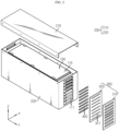
- FIG. 1 is a perspective view schematically showing a configuration of a battery module according to an embodiment of the present disclosure
- FIG. 2 is an exploded perspective view showing some components of FIG. 1 .
- the battery module includes a cell assembly 100, a module case 200, a bus bar assembly 300, and a blocking member 400.
- the cell assembly 100 may include a plurality of secondary batteries 110 (battery cells).
- the secondary battery 110 may include an electrode assembly, an electrolyte and a battery case.
- the secondary battery 110 may be a pouch-type secondary battery.
- other types of secondary batteries 110 such as a cylindrical battery or a prismatic battery, may also be adopted as the cell assembly 100.
- the plurality of secondary batteries 110 may be stacked in at least one direction to form the cell assembly 100.
- the plurality of secondary batteries 110 may be pouch-type batteries that are stacked up and down in a laid-down form.
- Each pouch-type secondary battery 110 may include electrode leads 111, which may be located at both ends or at one end of each secondary battery 110.
- a secondary battery 110 in which the electrode leads 111 protrude in both directions is called a bidirectional cell, and a secondary battery in which the electrode leads 111 protrude in one direction is called a unidirectional cell.
- the secondary battery 110 shown in FIGS. 1 and 2 is a bidirectional cell, and it may be regarded that the electrode leads 111 are positioned at both ends in the Y-axis direction.
- the secondary battery 110 of the battery module according to the present disclosure may also have a form in which the electrode leads 111 are positioned only at one end in the Y-axis direction, for example, the end in the +Y-axis direction.
- the present disclosure is not limited by any specific type or form of the secondary battery 110, and various types of secondary batteries 110 known at the time of filing of this application may be employed in the cell assembly 100 of the present disclosure. In this specification, a case where the secondary battery 110 is a bidirectional cell will be mainly described.
- the module case 200 may have an empty space formed therein and be configured to accommodate the cell assembly 100.
- the module case 200 may include an upper case 210 and a lower case 220, as shown in the drawings.
- the lower case 220 may include a lower plate and a side plate.
- the lower case 220 may further include a front plate and a rear plate.
- the lower case 220 may be formed by coupling the plates by fastening such as bolting or welding, but may also be manufactured in an integrated form.
- the upper case 210 and the lower case 220 may be coupled with each other to define an inner space.
- the cell assembly 100 may be accommodated in the inner space.
- the module case 200 may be configured such that at least one side is opened.
- the module case 200 may be configured such that the electrode leads 111 of the cell assembly 100 are positioned in the open portion.
- the cell assembly 100 may be configured such that the electrode leads 111 are positioned at both ends in the Y-axis direction and both ends of the module case 200 in the Y-axis direction are opened correspondingly.
- the bus bar assembly 300 may be coupled to the open portion. If the electrode leads 111 of the cell assembly 100 are positioned to protrude only in one side of the battery module, for example in the +Y-axis direction, the module case 200 may be configured to be opened only in the +Y-axis direction.
- the module case 200 may be configured to be closed except for the open portion to which the bus bar assembly 300 is coupled. Accordingly, when gas is generated inside the module case 200, the generated gas may be discharged only to the side where the bus bar assembly 300 is located.
- the bus bar assembly 300 may be configured to be positioned on at least one side of the module case 200, for example at both front and rear ends of the module case 200 (both ends in the Y-axis direction in FIG. 2 ).
- the bus bar assembly 300 may include a module bus bar 310 and a bus bar housing 320.
- the module bus bar 310 may be made of an electrically conductive material, for example a metal material such as copper or nickel.
- the module bus bar 310 may be configured to be electrically connected to the electrode leads 111 of the cell assembly 100.
- the module bus bar 310 may be welded or bolted in direct contact with the electrode leads 111.
- the module bus bar 310 may electrically connect the electrode leads 111 to each other or transmit voltage information sensed from the electrode leads 111 to an external control unit, for example a BMS (Battery Management System).
- BMS Battery Management System
- the bus bar housing 320 may be configured so that the module bus bar 310 may be placed thereon.
- the bus bar housing 320 may have a portion with a shape corresponding to the surface of the module bus bar 310, for example a planar shape, as a placing portion so that the module bus bar 310 is placed thereon.
- the bus bar housing 320 may support the module bus bar 310 so that the placed module bus bar 310 may stably maintain its position.
- the bus bar housing 320 may allow the module bus bar 310 to be coupled and fixed using various fastening methods such as bolting, riveting, fusion, and insertion.
- the bus bar housing 320 may be made of an electrically insulating material, such as plastic (polymer), such that it is not electrically connected to the module bus bar 310.
- the bus bar housing 320 may have a slot 321 through which the electrode lead 111 passes.
- the module bus bar 310 may be placed on the outer surface of the bus bar housing 320, and the electrode lead 111 may pass through the slot 321 at the inner side of the bus bar housing 320 and then come into contact with the module bus bar 310 located at an outer side.
- the inner side may mean an inner direction of the module case 200 in which the cell assembly 100 exists
- the outer side may mean an outer direction of the module case 200.
- the slot 321 may be formed in a shape corresponding to the shape of the electrode lead 111 so that the electrode lead 111 may easily pass therethrough.
- the slot 321 may be formed to be elongated in the left and right direction (X-axis direction in the drawing).
- a plurality of slots 321 may be formed in the bus bar housing 320.
- the pouch-type secondary batteries 110 are stacked in the vertical direction (the Z-axis direction in the drawing)
- a plurality of electrode leads 111 may exist in the vertical direction.
- the plurality of slots 321 may also be arranged to be spaced apart from each other by a predetermined distance in the vertical direction.
- the slot 321 may serve to penetrate the electrode lead 111 and support the electrode lead 111, and may additionally serve to discharge a vent gas.
- the slot 321 may have an empty gap around the electrode lead 111 in a state where the electrode lead 111 passes therethrough.
- the other part of the module case 200 may be configured in an almost sealed form. In this case, if a vent gas is generated due to a thermal propagation situation or the like in at least one of the secondary batteries 110 included in the cell assembly 100, the gas may increase the pressure inside the battery module.
- the slot 321 since the slot 321 has an empty gap formed around the electrode lead 111, the gas inside the battery module may be discharged to the outside through the slot 321. This will be described in more detail with reference to FIG. 3 .
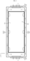
- FIG. 3 is a diagram schematically showing a discharge direction of an internal gas in the configuration of the battery module according to an embodiment of the present disclosure.
- FIG. 3 may be regarded as a diagram showing the internal configuration of the battery module of FIG. 2 , viewed from the above.
- the generated gas when gas is generated from at least one secondary battery 110 located inside the module, the generated gas may be discharged through the slot 321 formed in the bus bar assembly 300.
- the gas discharged from the vented portion may flow along the surface of the module case 200, for example the side plate of the lower case 220, move toward the bus bar assembly 300, and be discharged to the outside of the module through the slot 321, as indicated by the arrow in the drawing.
- the blocking member 400 may be located at the slot 321 of the bus bar housing 320.
- the configuration of the blocking member 400 will be described in more detail with reference to FIGS. 4 and 5 .
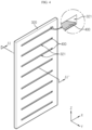
- FIG. 4 is a perspective view showing the bus bar housing 320 and the blocking member 400 according to an embodiment of the present disclosure, viewed from the outside of the battery module.
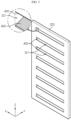
- FIG. 5 is a perspective view showing the configuration of FIG. 4 , viewed from the inside of the battery module.
- the plurality of slots 321 may be formed in the bus bar housing 320 to be arranged in the vertical direction, and the blocking member 400 may be located at each of the plurality of slots 321.
- the blocking member 400 may be provided to each slot 321.
- the blocking member 400 may be configured to transform its shape when heat is applied thereto. Also, the blocking member 400 may be configured to block at least a portion of the slot 321 due to the shape transformation. This will be described in more detail with reference to FIGS. 6 and 7 .
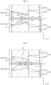
- FIGS. 6 and 7 are cross-sectional views schematically showing a shape-transformed configuration of the blocking member 400 according to an embodiment of the present disclosure.
- FIGS. 6 and 7 are cross-sectional views, taken along the line A1-A1' of FIG. 4 , and are illustrated based on one slot 321, wherein the module bus bar 310 and the electrode lead 111 are additionally depicted.
- FIG. 6 is a diagram showing the blocking member 400 before shape transformation
- FIG. 7 is a diagram showing the blocking member 400 after shape transformation.
- the blocking member 400 may be attached to the inner surface of the slot 321 formed in the bus bar housing 320.
- the blocking member 400 may be attached to the upper inner surface and the lower inner surface of the slot 321.
- the blocking member 400 may be configured to form an empty space between the electrode lead 111 and blocking member 400, as indicated by A2 and A2', in a normal state in which heat of a certain level or more is not applied.
- the blocking member 400 may be configured not to contact the electrode lead 111 in a normal state.
- a fluid, particularly a gas may flow in and out between the inside of the battery module (the left part of FIG.
- the venting gas may be discharged to the outside through the slot 321 as indicated by arrows in FIG. 6 .
- the shape of the blocking member 400 may be transformed as shown in FIG. 7 .
- the shape transformation of the blocking member 400 may be configured to block at least a portion of the slot 321.
- the empty space between the blocking member 400 and the electrode lead 111 indicated by A2 and A2' in FIG. 6 may be blocked by the blocking member 400 as indicated by A3 in FIG. 7 .
- the venting gas may be smoothly discharged to the outside of the battery module through the slot 321. Therefore, it is possible to prevent an explosion caused by an increase in the internal pressure of the battery module.
- the slot 321 may be blocked, so that the inflow of oxygen into the battery module through the slot 321 may be effectively blocked after the venting gas is discharged (see the dotted arrow in FIG. 7 ). Therefore, according to this configuration, it is possible to prevent a fire from occurring inside the battery module.
- a heat source such as a spark or a combustible material such as a gas or a component of the secondary battery 110 may exist inside the battery module.
- a heat source such as a spark or a combustible material such as a gas or a component of the secondary battery 110 may exist inside the battery module.
- one of three elements of combustion does not exist inside the battery module, so that combustion may be prevented inside the battery module.
- even when a small flame or fire occurs inside the battery module since the inflow of additional oxygen is blocked, it is possible to prevent the fire from spreading.
- the blocking member 400 may be configured to expand in volume when heat is applied.
- the blocking member 400 may be configured to block the empty space of the slot 321 due to the volume expansion.
- the blocking member 400 may gradually expand in volume to fill the empty space inside the slot 321 as shown in FIG. 7 . Accordingly, it is possible to prevent external oxygen from flowing into the battery module.
- the blocking member 400 may have various thermal expansion materials known at the time of filing of this application.
- the blocking member 400 may be configured to be thermally expandable by having various polymer materials such as PDMS (Poly-Di-Methyl-Siloxane), polyvinyl acetate, polystyrene, butyl (meth)acrylate, hexyl (meth)acrylate, n-octyl (meth)acrylate, isooctyl (meth)acrylate, 2-ethylhexyl (meth)acrylate, isononyl (meth)acrylate, and a urethane-based polymer.
- the blocking member 400 may further include a heat-resistant material.
- the blocking member 400 may be configured such that the outer surface is coated with a heat-resistant material such as ceramic, so that the blocking member 400 is not damaged while its volume is expanded by the heat of the venting gas.
- Thermal expansion of the blocking member 400 may be suitably set according to a type or a thermal expansion coefficient of the thermal expansion material included in the blocking member 400.
- the degree of thermal expansion of the blocking member 400 may be suitably set by a user according to various conditions, such as the size or shape of the blocking member 400 or the slot 321, and the type of the secondary batteries 110.
- the blocking member 400 may be configured to be more easily closed. That is, in configuring the blocking member 400 using a thermal expansion material, the configuration of blocking the slot 321 due to the application of heat may be more easily implemented.
- the venting gas may be discharged more smoothly. That is, when the blocking member 400 is expanded while the venting gas is discharged, the discharge space of the venting gas may be further reduced during the expansion process of the blocking member 400. Therefore, even if the amount of the venting gas present inside the battery module is not large, the discharge flow rate of the venting gas may not be significantly reduced since the size of the discharge hole is reduced. Accordingly, it is possible to allow the venting gas to be more reliably discharged, and it is also possible to more reliably block the inflow of external oxygen through the slot 321 due to the discharge pressure of the venting gas.
- the blocking member 400 may be configured to be positioned inside the bus bar housing 320.
- the module bus bar 310 may be located on the outer side of the bus bar housing 320 (+Y-axis direction in FIG. 2 ).
- the blocking member 400 may be located at the inner side of the bus bar housing 320 (-Y-axis direction in FIG. 2 ). That is, the blocking member 400 may be located on a part other than the outer surface of the bus bar housing.
- the blocking member 400 may be located in the inner space of the slot 321 in the bus bar housing 320. That is, the blocking member 400 may be configured to be positioned on a passage through which gas moves when the gas moves from the outside to the inside of the bus bar housing 320.
- the inflow of external oxygen may be more easily blocked by the blocking member 400.
- the blocking member 400 may be closed by the module bus bar 310 without interference.
- the blocking member 400 may be configured to be positioned at both sides based on the electrode lead 111.
- the electrode lead 111 may be formed in the form of a plate having two large surfaces, and the blocking member 400 may be positioned at both sides to face the two large surfaces, respectively.
- the blocking member 400 may be provided on both the upper side and the lower side of the electrode lead 111.
- the inflow of oxygen may be blocked more reliably by the blocking member 400.
- the blocking member 400 since oxygen may flow in at both sides of the electrode lead 111, if the blocking member 400 is positioned on both sides of the electrode lead 111 as in this embodiment, the sealing force around the electrode lead 111 may be secured to block the inflow of oxygen more effectively.
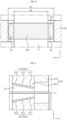
- the blocking member 400 may be configured to have a greater width than the electrode lead 111. This will be described in more detail with reference to FIG. 8 .
- FIG. 8 is a diagram schematically showing a width between the blocking member 400 and the electrode lead 111 in the battery module according to an embodiment of the present disclosure.
- FIG. 8 may be regarded as a diagram, viewed from the above based on one slot 321.
- the width of the blocking member 400 is indicated by W 1
- the width of the electrode lead 111 is indicated by W2.
- W1 may be formed to have a larger size than W2. That is, the blocking member 400 may be formed to have a greater width than the electrode lead 111.
- the blocking member 400 may be configured to protrude in both side directions of the electrode lead 111 (X-axis direction of FIG. 8 ).
- this configuration of the present disclosure since all of the periphery of the electrode lead 111, particularly the left and right sides of the electrode lead 111, is surrounded, it is possible to prevent a gap from being created around the electrode lead 111. That is, it is possible that not only the upper or lower portions of the electrode lead 111 but also the left and right sides of the electrode lead 111 are covered by the blocking member 400. In particular, this configuration may be obtained after the blocking member 400 is transformed due to heat. Therefore, in this case, it is possible to effectively block the inflow of oxygen by securing the sealing force around the electrode lead 111.
- the blocking member 400 includes an upper blocking member 410 and a lower blocking member 420, and the upper blocking member 410 and the lower blocking member 420 may be positioned at both sides (upper and lower sides) with respect to one electrode lead 111.
- the upper blocking member 410 and the lower blocking member 420 may be configured to expand due to heat and contact each other.
- the upper blocking member 410 and the lower blocking member 420 may be configured such that, due to thermal expansion, their portions protruding in the left and right directions further to the electrode lead 111 contact each other, as indicated by A4 and A4' in FIG. 8 .
- the blocking member 400 may be configured such that its width after thermal expansion is equal to the width of the slot 321 of the bus bar housing 320. That is, both the width of the blocking member 400 in the thermally expanded state and the width of the slot 321 may be the same as W1. In this case, the sealing property of the entire slot 321 may be stably secured. Moreover, the width of the blocking member 400 may also be obtained before thermal expansion. That is, the blocking member 400 may be configured to have the same width as the width of the slot 321 even before thermal expansion.
- the blocking member 400 may be configured in the form of a sheet, as shown in various drawings.
- the blocking member 400 may be configured in the form of a sheet made of a thermally expandable material, namely a thermally expandable sheet.
- one surface of the blocking member 400 may be attached to the inner surface of the bus bar housing 320, for example the inner surface of the slot 321, and the other surface of the blocking member 400 may be disposed to face the electrode lead 111.
- the blocking member 400 maybe included inside the slot 321 more easily. That is, since the blocking member 400 is formed in the form of a sheet, the blocking member 400 is formed to have a small thickness, and thus the blocking member 400 may be easily inserted into the inner space of the slot 321. Also, even if the size of the slot 321 is not great, the blocking member 400 may be positioned inside the slot 321. In addition, the blocking member 400 and the bus bar housing 320 may be easily coupled using an adhesive or the like. In addition, according to this configuration, when the electrode lead 111 is inserted into the slot 321, it is possible to minimize the deterioration of process efficiency caused by the blocking member 400.
- the bus bar housing 320 may be configured to have an inclined portion formed in the slot 321.
- the blocking member 400 may be configured to be positioned on the inclined portion of the slot 321.
- the inclined portion may be configured to be positioned at both sides based on the electrode lead 111.
- the bus bar housing 320 may be configured such that the inner surface of the slot 321 is inclined, as indicated by S1 and S 1' in FIG. 6 .
- the bus bar housing 320 may be configured so that both the upper surface of the slot 321 as indicated by S 1 and the lower surface of the slot 321 as indicated by S1' are inclined.
- the blocking member 400 may be configured to be provided on both the inclined portions, namely the upper inclined portion S1 and the lower inclined portion S1'.
- the process of inserting the electrode lead 111 from the inner side of the slot 321 to the outer side may be performed more smoothly.
- the slot 321 of the bus bar housing 320 may be formed to be gradually narrower as it goes from the inner side to the outer side. Therefore, when gas is vented, the discharge pressure is set high at the outer outlet of the slot 321, so that the inflow of oxygen into the slot 321 may be more reliably blocked.
- FIGS. 9 and 10 are cross-sectional views schematically showing a blocking member 400 according to another embodiment of the present disclosure.
- FIG. 9 shows a configuration before transformation of the blocking member 400
- FIG. 10 shows a configuration after transformation of the blocking member 400.
- a plurality of blocking members 400 may be arranged from the inside to the outside. That is, the blocking member 400 may include an upper blocking member 410 and a lower blocking member 420, and the upper blocking member 410 and the lower blocking member 420 may include a plurality of unit blocking members, respectively. Moreover, in FIG. 9 , the upper blocking member 410 and the lower blocking member 420 may include three unit blocking members, respectively. More specifically, the upper blocking member 410 and the lower blocking member 420 may include an outer blocking member 411, 421, a central blocking member 412, 422, and an inner blocking member 413, 423, respectively.
- the configuration for improving the oxygen inflow blocking effect by the blocking member 400 may be designed more diversely.
- the blocking member 400 may be set such that at least two blocking members 400 arranged from the inside to the outside have different thermal expansion coefficients.
- the three unit blocking members included in the upper blocking member 410 namely the outer blocking member 411, the central blocking member 412 and the inner blocking member 413, may be made of materials having different thermal expansion coefficients.
- the unit blocking members may be configured to have a greater thermal expansion coefficient as being positioned inside.
- the thermal expansion coefficient of the outer blocking member 411 may be lowest
- the thermal expansion coefficient of the inner blocking member 413 may be highest
- the thermal expansion of the central blocking member 412 may be middle.
- the three unit blocking members included in the lower blocking member 420 may also be designed in this way.
- the sealing force may be further improved. That is, according to this embodiment, as shown in FIG. 10 , if heat is applied to the upper blocking member 410, the degree of expansion may gradually increase from the outer blocking member 411 to the inner blocking member 413. Also, if heat is applied to the lower blocking member 420, the degree of expansion may gradually increase from the outer blocking member 421 to the inner blocking member 423. The inner space of the slot 321 may gradually increase from the outside to the inside. In this configuration, the degree of expansion of the unit blocking member located at the inner side is increased, the blocking member 400 may expand in a shape corresponding to the shape of the inner space of the slot 321. Therefore, in this case, the inner space of the slot 321 may be more reliably blocked.
- FIG. 11 is a cross-sectional view schematically showing a blocking member 400 according to still another embodiment of the present disclosure.
- FIG. 11 may be regarded as a configuration before transformation of the blocking member 400.
- features different from the former embodiments will also be described in detail.
- the blocking member 400 includes a plurality of unit blocking members arranged from the inside to the outside, but at least two unit blocking members among them have different thicknesses.
- the three unit blocking members provided in the upper blocking member 410 namely the outer blocking member 411, the central blocking member 412, and the inner blocking member 413, may be configured to have different thicknesses.
- the three unit blocking members may be configured to have a greater thickness from the outside to the inside.
- the thickness of the outer blocking member 411 may be smallest, the thickness of the inner blocking member 413 may be greatest, and the thickness of the central blocking member 412 may be middle.
- the three unit blocking members 421, 422, 423 included in the lower blocking member 420 may also be configured in this way.
- the sealing force may be further improved.
- the blocking member 400 may be configured to press the electrode lead 111 when heat is applied thereto to transform the shape.
- the upper blocking member 410 when the upper blocking member 410 is expanded, the upper blocking member 410 may be configured not only to contact the upper surface of the electrode lead 111 at the portion indicated by A3 but also to press the upper surface of the electrode lead 111 in the lower direction.
- the lower blocking member 420 when expanded, may be configured not only to contact the lower surface of the electrode lead 111 at the portion indicated by A3 but also to press the lower surface of the electrode lead 111 in the upper direction.
- the sealing force between the blocking member 400 and the electrode lead 111 may be further improved. Moreover, when the venting gas is discharged to the outside of the battery module, a negative pressure may be formed inside the battery module, so that the external gas containing oxygen may try to flow into the slot 321 with a considerable force. However, according to this embodiment, since the blocking member 400 and the electrode lead 111 may be sealed with a strong force, it is possible to more reliably block the inflow of oxygen.
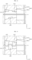
- FIGS. 12 and 13 are cross-sectional views schematically showing a blocking member 400 according to still another embodiment of the present disclosure.
- FIG. 12 shows a configuration before transformation of the blocking member 400
- FIG. 13 shows a configuration after transformation of the blocking member 400.
- features different from the former embodiments will also be described in detail.
- the blocking member 400 includes an upper blocking member 410 and a lower blocking member 420, and the upper blocking member 410 and the lower blocking member 420 may be alternately arranged from the inside to the outside.
- the center of the two upper blocking members 410 may be formed at a different position from the center of one lower blocking member 420.
- the oxygen inflow blocking effect by the blocking member 400 may be further improved.
- the electrode lead 111 may be bent, as shown in FIG. 13 . That is, the upper blocking member 410 may press the electrode lead 111 in the lower direction, and the lower blocking member 420 may press the electrode lead 111 in the upper direction.
- the electrode lead 111 may have a shape bent up and down, as shown in FIG. 13 . In this case, the adhesion between the blocking member 400 and the electrode lead 111 may be further increased.
- the space between the electrode lead 111 and the blocking member 400 is not formed in a straight line but is formed in a curve, a path for the inflow of oxygen may become long and complicated. Therefore, according to this embodiment, the effect of blocking oxygen that may flow in along the surface of the electrode lead 111 may be further improved.
- a battery pack according to the present disclosure may include a plurality of battery modules according to the present disclosure described above.
- the battery pack according to the present disclosure may further include various other components other than the battery module, for example components of the battery pack known at the time of filing of this application, such as a BMS, a bus bar, a pack case, a relay, a current sensor, and the like.
- An energy storage system may include at least one battery module according to the present disclosure.
- the energy storage system may include a plurality of battery modules according to the present disclosure in the form of being electrically connected to each other in order to have a large energy capacity.
- a plurality of battery modules according to the present disclosure may configure one batter pack, and the energy storage system may be configured to include a plurality of battery packs.
- the energy storage system according to the present disclosure may further include other various components of the energy storage system known at the time of filing of this application.
- the energy storage system may be used in various places or devices, such as a smart grid system or an electric charging station.
Landscapes
- Chemical & Material Sciences (AREA)
- Chemical Kinetics & Catalysis (AREA)
- Electrochemistry (AREA)
- General Chemical & Material Sciences (AREA)
- Health & Medical Sciences (AREA)
- Public Health (AREA)
- Business, Economics & Management (AREA)
- Emergency Management (AREA)
- Battery Mounting, Suspending (AREA)
- Connection Of Batteries Or Terminals (AREA)
- Secondary Cells (AREA)
Abstract
Description
- The present application claims priority to
Korean Patent Application No. 10-2021-0012619 filed on January 28, 2021 - The present disclosure relates to a battery, and more particularly, to a battery module capable of effectively preventing the occurrence or spread of fire, and a battery pack and an energy storage system including the same.
- In recent years, as the demand for portable electronic products such as laptops, video cameras and mobile phones has rapidly increased and robots, electric vehicles and the like are being commercialized in earnest, research on high-performance secondary batteries allowing repeatedly charging and discharging has been actively researched.
- Currently commercialized secondary batteries include nickel cadmium battery, nickel hydrogen battery, nickel zinc battery, lithium secondary battery, and so on. In particular, the lithium secondary battery has almost no memory effect to ensure free charge and discharge, compared to the nickel-based secondary battery, and the lithium secondary battery is spotlighted due to a very low discharge rate and a high energy density.
- The secondary battery may be used alone, but in general, a plurality of secondary batteries are electrically connected to each other in series and/or in parallel in many cases. In particular, the plurality of secondary batteries may be electrically connected to each other and accommodated in one module case, thereby configuring one battery module. In addition, the battery module may be used alone, or two or more battery modules may be electrically connected to each other in series and/or in parallel to configure a higher-level device such as a battery pack.
- Recently, as issues such as power shortage or eco-friendly energy have been highlighted, an energy storage system (ESS) for storing the generated power is receiving more attention. Representatively, if such an energy storage system is used, it is easy to construct a system such as a smart grid system, so that it is possible to easily control power supply and demand in a specific area or city.
- The battery pack used in an energy storage system may require a very large capacity, compared to a small-sized or medium-sized battery pack. Accordingly, the battery pack may typically include a large number of battery modules. In addition, in order to increase the energy density, the plurality of battery modules are often configured to be densely packed in a very narrow space.
- However, if the plurality of battery modules are concentrated in a narrow space as described above, they may be vulnerable to fire. For example, a thermal propagation situation may occur in one battery module, so that high-temperature gas is discharged from at least one battery cell. Moreover, high-temperature sparks may be ejected when the gas is discharged, and the sparks may include active materials or molten aluminum particles that are separated from the electrodes inside the battery cell. If these high-temperature sparks and high-temperature gas meet oxygen, it may generate a fire in the battery pack.
- In particular, when a fire occurs in a specific battery cell or module, it may spread to other neighboring battery cells, battery modules, or battery packs. In particular, since many batteries are concentrated in a narrow space of the energy storage system, if a fire occurs, it is not easy to suppress the fire. Moreover, considering the size and role of the energy storage system, there is a risk that the fire occurring inside the battery pack may cause very serious damage to property and human life. Therefore, even if a thermal propagation situation occurs in a specific battery cell or module, it is important to prevent this situation from progressing to a fire.
- The present disclosure is designed to solve the problems of the related art, and therefore the present disclosure is directed to providing a battery module configured to effectively suppress a fire even when high-temperature gas or sparks are generated therein due to thermal propagation, and a battery pack and an energy storage system including the same.
- However, the technical problems to be solved by the present disclosure are not limited to the above, and other problems not mentioned herein will be clearly understood by those skilled in the art from the following disclosure.
- In one aspect of the present disclosure, there is provided a battery module, comprising: a cell assembly configured such that secondary batteries having electrode leads are stacked in at least one direction; a module case configured to accommodate the cell assembly in an inner space thereof; a bus bar assembly located on at least one side of the module case and including a module bus bar made of an electrically conductive material and electrically connected to the electrode leads of the cell assembly and a bus bar housing configured so that the module bus bar is placed thereon and having a slot through which the electrode lead passes; and a blocking member located at the slot of the bus bar housing and configured to close at least a portion of the slot by transforming a shape thereof when heat is applied thereto.
- Here, the blocking member may be configured to expand in volume to close the empty space of the slot when heat is applied thereto.
- In addition, the blocking member may be located at an inner side of the bus bar housing.
- In addition, the blocking member may be located at both sides based on the electrode lead.
- In addition, the blocking member may be configured in a sheet form.
- In addition, the bus bar housing may be configured to have an inclined portion formed at the slot, and the blocking member may be located on the inclined portion.
- In addition, the blocking member may be provided in plural so that the plurality of blocking members are arranged from an inner side to an outer side.
- In addition, the blocking members may be set such that at least two blocking members arranged from an inner side to an outer side have different thermal expansion coefficients.
- In addition, the blocking member may be configured to press the electrode lead when the shape thereof is transformed since heat is applied thereto.
- In another aspect of the present disclosure, there is also provided a battery pack, comprising the battery module according to the present disclosure.
- In another aspect of the present disclosure, there is also provided an energy storage system, comprising the battery module according to the present disclosure.
- According to the present disclosure, it is possible to effectively prevent a fire from occurring in a battery module.
- In particular, according to an embodiment of the present disclosure, even if a high-temperature gas or spark is generated due to a thermal propagation phenomenon in a specific battery cell included in the battery module, it is possible to prevent it from progressing to a fire.
- Moreover, according to an embodiment of the present disclosure, it is possible to block the inflow of oxygen into the battery module while easily discharging the gas out of the battery module. Therefore, by excluding oxygen, which is one of the three elements of combustion, it is possible to fundamentally block the occurrence of combustion, namely a fire, inside the battery module.
- In addition, according to an embodiment of the present disclosure, even if a fire occurs inside the battery module, the inflow of additional oxygen is blocked so that the fire can be rapidly extinguished without spreading.
- In addition, the present disclosure may have various other effects, and such effects will be described in each embodiment, or any effect that can be easily inferred by those skilled in the art will not be described in detail.
- The accompanying drawings illustrate a preferred embodiment of the present disclosure and together with the foregoing disclosure, serve to provide further understanding of the technical features of the present disclosure, and thus, the present disclosure is not construed as being limited to the drawing.
-
FIG. 1 is a perspective view schematically showing a configuration of a battery module according to an embodiment of the present disclosure. -
FIG. 2 is an exploded perspective view showing some components ofFIG. 1 . -
FIG. 3 is a diagram schematically showing a discharge direction of an internal gas in the configuration of the battery module according to an embodiment of the present disclosure. -
FIG. 4 is a perspective view showing a bus bar housing and a blocking member according to an embodiment of the present disclosure, viewed from the outside of the battery module. -
FIG. 5 is a perspective view showing the configuration ofFIG. 4 , viewed from the inside of the battery module. -
FIGS. 6 and 7 are cross-sectional views schematically showing a shape-transformed configuration of the blocking member according to an embodiment of the present disclosure. -
FIG. 8 is a diagram schematically showing a width between the blocking member and the electrode lead in the battery module according to an embodiment of the present disclosure. -
FIGS. 9 and10 are cross-sectional views schematically showing the configuration of a blocking member according to another embodiment of the present disclosure. -
FIG. 11 is a cross-sectional view schematically showing the configuration of a blocking member according to still another embodiment of the present disclosure. -
FIGS. 12 and 13 are cross-sectional views schematically showing the configuration of a blocking member according to still another embodiment of the present disclosure. - Hereinafter, preferred embodiments of the present disclosure will be described in detail with reference to the accompanying drawings. Prior to the description, it should be understood that the terms used in the specification and the appended claims should not be construed as limited to general and dictionary meanings, but interpreted based on the meanings and concepts corresponding to technical aspects of the present disclosure on the basis of the principle that the inventor is allowed to define terms appropriately for the best explanation.
- Therefore, the description proposed herein is just a preferable example for the purpose of illustrations only, not intended to limit the scope of the disclosure, so it should be understood that other equivalents and modifications could be made thereto without departing from the scope of the disclosure.
-
FIG. 1 is a perspective view schematically showing a configuration of a battery module according to an embodiment of the present disclosure, andFIG. 2 is an exploded perspective view showing some components ofFIG. 1 . - Referring to
FIGS. 1 and2 , the battery module according to the present disclosure includes acell assembly 100, amodule case 200, abus bar assembly 300, and ablocking member 400. - The
cell assembly 100 may include a plurality of secondary batteries 110 (battery cells). Thesecondary battery 110 may include an electrode assembly, an electrolyte and a battery case. In particular, as shown inFIGS. 1 and2 , thesecondary battery 110 may be a pouch-type secondary battery. However, other types ofsecondary batteries 110, such as a cylindrical battery or a prismatic battery, may also be adopted as thecell assembly 100. - The plurality of
secondary batteries 110 may be stacked in at least one direction to form thecell assembly 100. For example, as shown in the drawings, the plurality ofsecondary batteries 110 may be pouch-type batteries that are stacked up and down in a laid-down form. Each pouch-typesecondary battery 110 may include electrode leads 111, which may be located at both ends or at one end of eachsecondary battery 110. Asecondary battery 110 in which the electrode leads 111 protrude in both directions is called a bidirectional cell, and a secondary battery in which the electrode leads 111 protrude in one direction is called a unidirectional cell. For example, thesecondary battery 110 shown inFIGS. 1 and2 is a bidirectional cell, and it may be regarded that the electrode leads 111 are positioned at both ends in the Y-axis direction. However, thesecondary battery 110 of the battery module according to the present disclosure may also have a form in which the electrode leads 111 are positioned only at one end in the Y-axis direction, for example, the end in the +Y-axis direction. The present disclosure is not limited by any specific type or form of thesecondary battery 110, and various types ofsecondary batteries 110 known at the time of filing of this application may be employed in thecell assembly 100 of the present disclosure. In this specification, a case where thesecondary battery 110 is a bidirectional cell will be mainly described. - The
module case 200 may have an empty space formed therein and be configured to accommodate thecell assembly 100. For example, themodule case 200 may include anupper case 210 and alower case 220, as shown in the drawings. In this case, thelower case 220 may include a lower plate and a side plate. Additionally, thelower case 220 may further include a front plate and a rear plate. Thelower case 220 may be formed by coupling the plates by fastening such as bolting or welding, but may also be manufactured in an integrated form. Theupper case 210 and thelower case 220 may be coupled with each other to define an inner space. In addition, thecell assembly 100 may be accommodated in the inner space. - The
module case 200 may be configured such that at least one side is opened. In addition, themodule case 200 may be configured such that the electrode leads 111 of thecell assembly 100 are positioned in the open portion. For example, referring toFIG. 2 , thecell assembly 100 may be configured such that the electrode leads 111 are positioned at both ends in the Y-axis direction and both ends of themodule case 200 in the Y-axis direction are opened correspondingly. In addition, thebus bar assembly 300 may be coupled to the open portion. If the electrode leads 111 of thecell assembly 100 are positioned to protrude only in one side of the battery module, for example in the +Y-axis direction, themodule case 200 may be configured to be opened only in the +Y-axis direction. Themodule case 200 may be configured to be closed except for the open portion to which thebus bar assembly 300 is coupled. Accordingly, when gas is generated inside themodule case 200, the generated gas may be discharged only to the side where thebus bar assembly 300 is located. - As described above, the
bus bar assembly 300 may be configured to be positioned on at least one side of themodule case 200, for example at both front and rear ends of the module case 200 (both ends in the Y-axis direction inFIG. 2 ). In addition, thebus bar assembly 300 may include amodule bus bar 310 and abus bar housing 320. - Here, the
module bus bar 310 may be made of an electrically conductive material, for example a metal material such as copper or nickel. In addition, themodule bus bar 310 may be configured to be electrically connected to the electrode leads 111 of thecell assembly 100. In particular, themodule bus bar 310 may be welded or bolted in direct contact with the electrode leads 111. In addition, themodule bus bar 310 may electrically connect the electrode leads 111 to each other or transmit voltage information sensed from the electrode leads 111 to an external control unit, for example a BMS (Battery Management System). - In addition, the
bus bar housing 320 may be configured so that themodule bus bar 310 may be placed thereon. For example, thebus bar housing 320 may have a portion with a shape corresponding to the surface of themodule bus bar 310, for example a planar shape, as a placing portion so that themodule bus bar 310 is placed thereon. In addition, thebus bar housing 320 may support themodule bus bar 310 so that the placedmodule bus bar 310 may stably maintain its position. For example, thebus bar housing 320 may allow themodule bus bar 310 to be coupled and fixed using various fastening methods such as bolting, riveting, fusion, and insertion. Thebus bar housing 320 may be made of an electrically insulating material, such as plastic (polymer), such that it is not electrically connected to themodule bus bar 310. - The
bus bar housing 320 may have aslot 321 through which theelectrode lead 111 passes. In general, for the stable coupling, themodule bus bar 310 may be placed on the outer surface of thebus bar housing 320, and theelectrode lead 111 may pass through theslot 321 at the inner side of thebus bar housing 320 and then come into contact with themodule bus bar 310 located at an outer side. Meanwhile, unless stated otherwise in this specification, the inner side may mean an inner direction of themodule case 200 in which thecell assembly 100 exists, and the outer side may mean an outer direction of themodule case 200. - The
slot 321 may be formed in a shape corresponding to the shape of theelectrode lead 111 so that theelectrode lead 111 may easily pass therethrough. For example, as shown in the drawings, theslot 321 may be formed to be elongated in the left and right direction (X-axis direction in the drawing). In addition, a plurality ofslots 321 may be formed in thebus bar housing 320. Moreover, if the pouch-typesecondary batteries 110 are stacked in the vertical direction (the Z-axis direction in the drawing), a plurality of electrode leads 111 may exist in the vertical direction. Accordingly, as shown inFIG. 2 , the plurality ofslots 321 may also be arranged to be spaced apart from each other by a predetermined distance in the vertical direction. - The
slot 321 may serve to penetrate theelectrode lead 111 and support theelectrode lead 111, and may additionally serve to discharge a vent gas. Theslot 321 may have an empty gap around theelectrode lead 111 in a state where theelectrode lead 111 passes therethrough. In addition, the other part of themodule case 200 may be configured in an almost sealed form. In this case, if a vent gas is generated due to a thermal propagation situation or the like in at least one of thesecondary batteries 110 included in thecell assembly 100, the gas may increase the pressure inside the battery module. However, since theslot 321 has an empty gap formed around theelectrode lead 111, the gas inside the battery module may be discharged to the outside through theslot 321. This will be described in more detail with reference toFIG. 3 . -
FIG. 3 is a diagram schematically showing a discharge direction of an internal gas in the configuration of the battery module according to an embodiment of the present disclosure. In particular,FIG. 3 may be regarded as a diagram showing the internal configuration of the battery module ofFIG. 2 , viewed from the above. - Referring to
FIG. 3 , when gas is generated from at least onesecondary battery 110 located inside the module, the generated gas may be discharged through theslot 321 formed in thebus bar assembly 300. In particular, when gas is generated inside the pouch-typesecondary battery 110 to increase the internal pressure, there is a high possibility that a side edge is vented, rather than an edge where theelectrode lead 111 is located. In addition, if the side edge is vented in this way, the gas discharged from the vented portion may flow along the surface of themodule case 200, for example the side plate of thelower case 220, move toward thebus bar assembly 300, and be discharged to the outside of the module through theslot 321, as indicated by the arrow in the drawing. - The blocking
member 400 may be located at theslot 321 of thebus bar housing 320. The configuration of the blockingmember 400 will be described in more detail with reference toFIGS. 4 and5 . -
FIG. 4 is a perspective view showing thebus bar housing 320 and the blockingmember 400 according to an embodiment of the present disclosure, viewed from the outside of the battery module.FIG. 5 is a perspective view showing the configuration ofFIG. 4 , viewed from the inside of the battery module. - Referring to
FIGS. 4 and5 , the plurality ofslots 321 may be formed in thebus bar housing 320 to be arranged in the vertical direction, and the blockingmember 400 may be located at each of the plurality ofslots 321. For example, if eightslots 321 are formed in thebus bar housing 320 in the vertical direction and one or more electrode leads 111 are inserted into each of theslots 321, the blockingmember 400 may be provided to eachslot 321. - The blocking
member 400 may be configured to transform its shape when heat is applied thereto. Also, the blockingmember 400 may be configured to block at least a portion of theslot 321 due to the shape transformation. This will be described in more detail with reference toFIGS. 6 and 7 . -
FIGS. 6 and 7 are cross-sectional views schematically showing a shape-transformed configuration of the blockingmember 400 according to an embodiment of the present disclosure. For example,FIGS. 6 and 7 are cross-sectional views, taken along the line A1-A1' ofFIG. 4 , and are illustrated based on oneslot 321, wherein themodule bus bar 310 and theelectrode lead 111 are additionally depicted. More specifically,FIG. 6 is a diagram showing the blockingmember 400 before shape transformation, andFIG. 7 is a diagram showing the blockingmember 400 after shape transformation. - First, referring to
FIG. 6 , the blockingmember 400 may be attached to the inner surface of theslot 321 formed in thebus bar housing 320. In particular, the blockingmember 400 may be attached to the upper inner surface and the lower inner surface of theslot 321. In this case, the blockingmember 400 may be configured to form an empty space between theelectrode lead 111 and blockingmember 400, as indicated by A2 and A2', in a normal state in which heat of a certain level or more is not applied. For example, the blockingmember 400 may be configured not to contact theelectrode lead 111 in a normal state. In addition, due to the empty space in theslot 321, a fluid, particularly a gas, may flow in and out between the inside of the battery module (the left part ofFIG. 6 ) and the outside of the battery module (the right part ofFIG. 6 ). Moreover, when gas is vented due to thermal propagation in a specific cell inside the battery module, the venting gas may be discharged to the outside through theslot 321 as indicated by arrows inFIG. 6 . - However, if the heat generated due to the thermal propagation of a specific cell is transferred to the blocking
member 400 at a certain level or higher, or if the heat of the venting gas is transferred to the blockingmember 400 at a certain level or higher, the shape of the blockingmember 400 may be transformed as shown inFIG. 7 . In particular, the shape transformation of the blockingmember 400 may be configured to block at least a portion of theslot 321. For example, the empty space between the blockingmember 400 and theelectrode lead 111 indicated by A2 and A2' inFIG. 6 may be blocked by the blockingmember 400 as indicated by A3 inFIG. 7 . - According to this configuration of the present disclosure, if gas is vented due to a thermal propagation situation or the like occurring inside the battery module, the venting gas may be smoothly discharged to the outside of the battery module through the
slot 321. Therefore, it is possible to prevent an explosion caused by an increase in the internal pressure of the battery module. In addition, due to the heat transferred while the venting gas is discharged, theslot 321 may be blocked, so that the inflow of oxygen into the battery module through theslot 321 may be effectively blocked after the venting gas is discharged (see the dotted arrow inFIG. 7 ). Therefore, according to this configuration, it is possible to prevent a fire from occurring inside the battery module. - Moreover, a heat source such as a spark or a combustible material such as a gas or a component of the
secondary battery 110 may exist inside the battery module. However, if the inflow of oxygen is blocked as described above, one of three elements of combustion does not exist inside the battery module, so that combustion may be prevented inside the battery module. In addition, even when a small flame or fire occurs inside the battery module, since the inflow of additional oxygen is blocked, it is possible to prevent the fire from spreading. - In particular, the blocking
member 400 may be configured to expand in volume when heat is applied. In addition, the blockingmember 400 may be configured to block the empty space of theslot 321 due to the volume expansion. - That is, if heat is applied, the blocking
member 400 may gradually expand in volume to fill the empty space inside theslot 321 as shown inFIG. 7 . Accordingly, it is possible to prevent external oxygen from flowing into the battery module. - To this end, the blocking
member 400 may have various thermal expansion materials known at the time of filing of this application. For example, the blockingmember 400 may be configured to be thermally expandable by having various polymer materials such as PDMS (Poly-Di-Methyl-Siloxane), polyvinyl acetate, polystyrene, butyl (meth)acrylate, hexyl (meth)acrylate, n-octyl (meth)acrylate, isooctyl (meth)acrylate, 2-ethylhexyl (meth)acrylate, isononyl (meth)acrylate, and a urethane-based polymer. In addition, the blockingmember 400 may further include a heat-resistant material. For example, the blockingmember 400 may be configured such that the outer surface is coated with a heat-resistant material such as ceramic, so that the blockingmember 400 is not damaged while its volume is expanded by the heat of the venting gas. - Thermal expansion of the blocking
member 400 may be suitably set according to a type or a thermal expansion coefficient of the thermal expansion material included in the blockingmember 400. In addition, the degree of thermal expansion of the blockingmember 400 may be suitably set by a user according to various conditions, such as the size or shape of the blockingmember 400 or theslot 321, and the type of thesecondary batteries 110. - According to the embodiment of the present disclosure, the blocking
member 400 may be configured to be more easily closed. That is, in configuring the blockingmember 400 using a thermal expansion material, the configuration of blocking theslot 321 due to the application of heat may be more easily implemented. In addition, according to this embodiment, the venting gas may be discharged more smoothly. That is, when the blockingmember 400 is expanded while the venting gas is discharged, the discharge space of the venting gas may be further reduced during the expansion process of the blockingmember 400. Therefore, even if the amount of the venting gas present inside the battery module is not large, the discharge flow rate of the venting gas may not be significantly reduced since the size of the discharge hole is reduced. Accordingly, it is possible to allow the venting gas to be more reliably discharged, and it is also possible to more reliably block the inflow of external oxygen through theslot 321 due to the discharge pressure of the venting gas. - The blocking
member 400 may be configured to be positioned inside thebus bar housing 320. - For example, referring to
FIG. 2 , based on thebus bar housing 320 located at the front side of the battery module, themodule bus bar 310 may be located on the outer side of the bus bar housing 320 (+Y-axis direction inFIG. 2 ). In addition, the blockingmember 400 may be located at the inner side of the bus bar housing 320 (-Y-axis direction inFIG. 2 ). That is, the blockingmember 400 may be located on a part other than the outer surface of the bus bar housing. - In particular, the blocking
member 400 may be located in the inner space of theslot 321 in thebus bar housing 320. That is, the blockingmember 400 may be configured to be positioned on a passage through which gas moves when the gas moves from the outside to the inside of thebus bar housing 320. - According to this embodiment of the present disclosure, the inflow of external oxygen may be more easily blocked by the blocking
member 400. Moreover, since themodule bus bar 310 may be attached to the outer surface of thebus bar housing 320, in this case, the blockingmember 400 may be closed by themodule bus bar 310 without interference. - In addition, the blocking
member 400 may be configured to be positioned at both sides based on theelectrode lead 111. In particular, theelectrode lead 111 may be formed in the form of a plate having two large surfaces, and the blockingmember 400 may be positioned at both sides to face the two large surfaces, respectively. - For example, referring to
FIG. 6 , in a state where theelectrode lead 111 is inserted into theslot 321, the blockingmember 400 may be provided on both the upper side and the lower side of theelectrode lead 111. - According to this configuration of the present disclosure, the inflow of oxygen may be blocked more reliably by the blocking
member 400. In particular, since oxygen may flow in at both sides of theelectrode lead 111, if the blockingmember 400 is positioned on both sides of theelectrode lead 111 as in this embodiment, the sealing force around theelectrode lead 111 may be secured to block the inflow of oxygen more effectively. - In addition, the blocking
member 400 may be configured to have a greater width than theelectrode lead 111. This will be described in more detail with reference toFIG. 8 . -
FIG. 8 is a diagram schematically showing a width between the blockingmember 400 and theelectrode lead 111 in the battery module according to an embodiment of the present disclosure. In particular,FIG. 8 may be regarded as a diagram, viewed from the above based on oneslot 321. - Referring to
FIG. 8 , the width of the blockingmember 400 is indicated by W 1, and the width of theelectrode lead 111 is indicated by W2. In this case, W1 may be formed to have a larger size than W2. That is, the blockingmember 400 may be formed to have a greater width than theelectrode lead 111. In addition, when the blockingmember 400 and theelectrode lead 111 are viewed from the above, the blockingmember 400 may be configured to protrude in both side directions of the electrode lead 111 (X-axis direction ofFIG. 8 ). - According to this configuration of the present disclosure, since all of the periphery of the
electrode lead 111, particularly the left and right sides of theelectrode lead 111, is surrounded, it is possible to prevent a gap from being created around theelectrode lead 111. That is, it is possible that not only the upper or lower portions of theelectrode lead 111 but also the left and right sides of theelectrode lead 111 are covered by the blockingmember 400. In particular, this configuration may be obtained after the blockingmember 400 is transformed due to heat. Therefore, in this case, it is possible to effectively block the inflow of oxygen by securing the sealing force around theelectrode lead 111. - Moreover, as shown in
FIGS. 6 and 7 , the blockingmember 400 includes anupper blocking member 410 and alower blocking member 420, and theupper blocking member 410 and thelower blocking member 420 may be positioned at both sides (upper and lower sides) with respect to oneelectrode lead 111. In this case, theupper blocking member 410 and thelower blocking member 420 may be configured to expand due to heat and contact each other. For example, theupper blocking member 410 and thelower blocking member 420 may be configured such that, due to thermal expansion, their portions protruding in the left and right directions further to theelectrode lead 111 contact each other, as indicated by A4 and A4' inFIG. 8 . - According to this configuration of the present disclosure, due to the contact of the
upper blocking member 410 and thelower blocking member 420, sealing properties of the side surfaces of theelectrode lead 111 may be stably secured. - In particular, in this embodiment, the blocking
member 400 may be configured such that its width after thermal expansion is equal to the width of theslot 321 of thebus bar housing 320. That is, both the width of the blockingmember 400 in the thermally expanded state and the width of theslot 321 may be the same as W1. In this case, the sealing property of theentire slot 321 may be stably secured. Moreover, the width of the blockingmember 400 may also be obtained before thermal expansion. That is, the blockingmember 400 may be configured to have the same width as the width of theslot 321 even before thermal expansion. - The blocking
member 400 may be configured in the form of a sheet, as shown in various drawings. In particular, the blockingmember 400 may be configured in the form of a sheet made of a thermally expandable material, namely a thermally expandable sheet. In this case, one surface of the blockingmember 400 may be attached to the inner surface of thebus bar housing 320, for example the inner surface of theslot 321, and the other surface of the blockingmember 400 may be disposed to face theelectrode lead 111. - According to this configuration of the present disclosure, the blocking
member 400 maybe included inside theslot 321 more easily. That is, since the blockingmember 400 is formed in the form of a sheet, the blockingmember 400 is formed to have a small thickness, and thus the blockingmember 400 may be easily inserted into the inner space of theslot 321. Also, even if the size of theslot 321 is not great, the blockingmember 400 may be positioned inside theslot 321. In addition, the blockingmember 400 and thebus bar housing 320 may be easily coupled using an adhesive or the like. In addition, according to this configuration, when theelectrode lead 111 is inserted into theslot 321, it is possible to minimize the deterioration of process efficiency caused by the blockingmember 400. - The
bus bar housing 320 may be configured to have an inclined portion formed in theslot 321. In addition, the blockingmember 400 may be configured to be positioned on the inclined portion of theslot 321. In particular, the inclined portion may be configured to be positioned at both sides based on theelectrode lead 111. - For example, the
bus bar housing 320 may be configured such that the inner surface of theslot 321 is inclined, as indicated by S1 and S 1' inFIG. 6 . In particular, thebus bar housing 320 may be configured so that both the upper surface of theslot 321 as indicated by S 1 and the lower surface of theslot 321 as indicated by S1' are inclined. In addition, the blockingmember 400 may be configured to be provided on both the inclined portions, namely the upper inclined portion S1 and the lower inclined portion S1'. - According to this configuration of the present disclosure, the process of inserting the
electrode lead 111 from the inner side of theslot 321 to the outer side may be performed more smoothly. In addition, according to this configuration, theslot 321 of thebus bar housing 320 may be formed to be gradually narrower as it goes from the inner side to the outer side. Therefore, when gas is vented, the discharge pressure is set high at the outer outlet of theslot 321, so that the inflow of oxygen into theslot 321 may be more reliably blocked. -
FIGS. 9 and10 are cross-sectional views schematically showing a blockingmember 400 according to another embodiment of the present disclosure. In particular,FIG. 9 shows a configuration before transformation of the blockingmember 400, andFIG. 10 shows a configuration after transformation of the blockingmember 400. With respect to this embodiment, features different from those of the former embodiments will be described in detail, and features substantially identical or similar to those of the former embodiments will not be described in detail again. - First, referring to
FIG. 9 , a plurality of blockingmembers 400 may be arranged from the inside to the outside. That is, the blockingmember 400 may include anupper blocking member 410 and alower blocking member 420, and theupper blocking member 410 and thelower blocking member 420 may include a plurality of unit blocking members, respectively. Moreover, inFIG. 9 , theupper blocking member 410 and thelower blocking member 420 may include three unit blocking members, respectively. More specifically, theupper blocking member 410 and thelower blocking member 420 may include anouter blocking member central blocking member inner blocking member - According to this configuration of the present disclosure, the configuration for improving the oxygen inflow blocking effect by the blocking
member 400 may be designed more diversely. - In particular, the blocking
member 400 may be set such that at least two blockingmembers 400 arranged from the inside to the outside have different thermal expansion coefficients. - For example, in the configuration of
FIG. 9 , the three unit blocking members included in theupper blocking member 410, namely the outer blockingmember 411, thecentral blocking member 412 and theinner blocking member 413, may be made of materials having different thermal expansion coefficients. - Moreover, in this case, the unit blocking members may be configured to have a greater thermal expansion coefficient as being positioned inside. For example, among three unit blocking members included in the
upper blocking member 410, the thermal expansion coefficient of the outer blockingmember 411 may be lowest, the thermal expansion coefficient of theinner blocking member 413 may be highest, and the thermal expansion of thecentral blocking member 412 may be middle. In addition, the three unit blocking members included in thelower blocking member 420 may also be designed in this way. - According to this configuration of the present disclosure, with respect to the inner space of the
slot 321 in which the inclined portion is formed, the sealing force may be further improved. That is, according to this embodiment, as shown inFIG. 10 , if heat is applied to theupper blocking member 410, the degree of expansion may gradually increase from the outer blockingmember 411 to theinner blocking member 413. Also, if heat is applied to thelower blocking member 420, the degree of expansion may gradually increase from the outer blockingmember 421 to theinner blocking member 423. The inner space of theslot 321 may gradually increase from the outside to the inside. In this configuration, the degree of expansion of the unit blocking member located at the inner side is increased, the blockingmember 400 may expand in a shape corresponding to the shape of the inner space of theslot 321. Therefore, in this case, the inner space of theslot 321 may be more reliably blocked. -
FIG. 11 is a cross-sectional view schematically showing a blockingmember 400 according to still another embodiment of the present disclosure. In particular,FIG. 11 may be regarded as a configuration before transformation of the blockingmember 400. For this embodiment, features different from the former embodiments will also be described in detail. - Referring to
FIG. 11 , as in the former embodiment ofFIG. 9 , the blockingmember 400 includes a plurality of unit blocking members arranged from the inside to the outside, but at least two unit blocking members among them have different thicknesses. For example, the three unit blocking members provided in theupper blocking member 410, namely the outer blockingmember 411, thecentral blocking member 412, and theinner blocking member 413, may be configured to have different thicknesses. - In particular, in this configuration, the three unit blocking members may be configured to have a greater thickness from the outside to the inside. For example, in the configuration of
FIG. 11 , the thickness of the outer blockingmember 411 may be smallest, the thickness of theinner blocking member 413 may be greatest, and the thickness of thecentral blocking member 412 may be middle. In addition, the threeunit blocking members lower blocking member 420 may also be configured in this way. - According to this configuration of the present disclosure, with respect to the inner space of the
slot 321 in which the inclined portion is formed, the sealing force may be further improved. In particular, according to this embodiment, even if the thermal expansion coefficients of the unit blocking members are the same, there may be a difference in the final expansion thickness of each unit blocking member due to the difference in thickness. Therefore, in this case, if heat is applied to each unit blocking member, the expansion form as shown inFIG. 10 may be implemented. - The blocking
member 400 may be configured to press theelectrode lead 111 when heat is applied thereto to transform the shape. - For example, referring to
FIG. 7 , when theupper blocking member 410 is expanded, theupper blocking member 410 may be configured not only to contact the upper surface of theelectrode lead 111 at the portion indicated by A3 but also to press the upper surface of theelectrode lead 111 in the lower direction. In addition, when expanded, thelower blocking member 420 may be configured not only to contact the lower surface of theelectrode lead 111 at the portion indicated by A3 but also to press the lower surface of theelectrode lead 111 in the upper direction. - According to this configuration of the present disclosure, the sealing force between the blocking
member 400 and theelectrode lead 111 may be further improved. Moreover, when the venting gas is discharged to the outside of the battery module, a negative pressure may be formed inside the battery module, so that the external gas containing oxygen may try to flow into theslot 321 with a considerable force. However, according to this embodiment, since the blockingmember 400 and theelectrode lead 111 may be sealed with a strong force, it is possible to more reliably block the inflow of oxygen. -
FIGS. 12 and 13 are cross-sectional views schematically showing a blockingmember 400 according to still another embodiment of the present disclosure. In particular,FIG. 12 shows a configuration before transformation of the blockingmember 400, andFIG. 13 shows a configuration after transformation of the blockingmember 400. For this embodiment, features different from the former embodiments will also be described in detail. - First, referring to
FIG. 12 , the blockingmember 400 includes anupper blocking member 410 and alower blocking member 420, and theupper blocking member 410 and thelower blocking member 420 may be alternately arranged from the inside to the outside. For example, in the left and right direction (Y-axis direction) in the drawing, the center of the twoupper blocking members 410 may be formed at a different position from the center of onelower blocking member 420. - According to this configuration of the present disclosure, the oxygen inflow blocking effect by the blocking
member 400 may be further improved. In particular, when theupper blocking member 410 and thelower blocking member 420 in this configuration are configured to press theelectrode lead 111 during expansion, theelectrode lead 111 may be bent, as shown inFIG. 13 . That is, theupper blocking member 410 may press theelectrode lead 111 in the lower direction, and thelower blocking member 420 may press theelectrode lead 111 in the upper direction. In addition, since the pressing directions are alternated, theelectrode lead 111 may have a shape bent up and down, as shown inFIG. 13 . In this case, the adhesion between the blockingmember 400 and theelectrode lead 111 may be further increased. In addition, since the space between theelectrode lead 111 and the blockingmember 400 is not formed in a straight line but is formed in a curve, a path for the inflow of oxygen may become long and complicated. Therefore, according to this embodiment, the effect of blocking oxygen that may flow in along the surface of theelectrode lead 111 may be further improved. - A battery pack according to the present disclosure may include a plurality of battery modules according to the present disclosure described above. In addition, the battery pack according to the present disclosure may further include various other components other than the battery module, for example components of the battery pack known at the time of filing of this application, such as a BMS, a bus bar, a pack case, a relay, a current sensor, and the like.
- An energy storage system according to the present disclosure may include at least one battery module according to the present disclosure. In particular, the energy storage system may include a plurality of battery modules according to the present disclosure in the form of being electrically connected to each other in order to have a large energy capacity. Alternatively, a plurality of battery modules according to the present disclosure may configure one batter pack, and the energy storage system may be configured to include a plurality of battery packs. In addition, the energy storage system according to the present disclosure may further include other various components of the energy storage system known at the time of filing of this application. Moreover, the energy storage system may be used in various places or devices, such as a smart grid system or an electric charging station.
- Meanwhile, in this specification, terms indicating directions such as "upper", "lower", "left", "right", "front", and "rear" are used, but these terms are just for convenience of explanation, and it is obvious to those skilled in the art that these terms may vary depending on the location of an object or the position of an observer.
- The present disclosure has been described in detail. However, it should be understood that the detailed description and specific examples, while indicating preferred embodiments of the disclosure, are given by way of illustration only, since various changes and modifications within the scope of the disclosure will become apparent to those skilled in the art from this detailed description.
-
- 100: cell assembly
- 110: secondary battery
- 111: electrode lead
- 200: module case
- 210: upper case, 220: lower case
- 300: bus bar assembly
- 310: module bus bar, 320: bus bar housing
- 321: slot
- 400: blocking member
- 410: upper blocking member, 420: lower blocking member
- 411, 421: outer blocking member
- 412, 422: central blocking member
- 413, 423: inner blocking member
Claims (11)
- A battery module, comprising:a cell assembly configured such that secondary batteries having electrode leads are stacked in at least one direction;a module case configured to accommodate the cell assembly in an inner space thereof;a bus bar assembly located on at least one side of the module case and including a module bus bar made of an electrically conductive material and electrically connected to the electrode leads of the cell assembly and a bus bar housing configured so that the module bus bar is placed thereon and having a slot through which the electrode lead passes; anda blocking member located at the slot of the bus bar housing and configured to close at least a portion of the slot by transforming a shape thereof when heat is applied thereto.
- The battery module according to claim 1,
wherein the blocking member is configured to expand in volume to close the empty space of the slot when heat is applied thereto. - The battery module according to claim 1,
wherein the blocking member is located at an inner side of the bus bar housing. - The battery module according to claim 1,
wherein the blocking member is located at both sides based on the electrode lead. - The battery module according to claim 1,
wherein the blocking member is configured in a sheet form. - The battery module according to claim 1,wherein the bus bar housing is configured to have an inclined portion formed at the slot, andthe blocking member is located on the inclined portion.
- The battery module according to claim 1,
wherein the blocking member is provided in plural so that the plurality of blocking members are arranged from an inner side to an outer side. - The battery module according to claim 7,
wherein the blocking members are set such that at least two blocking members arranged from an inner side to an outer side have different thermal expansion coefficients. - The battery module according to claim 1,
wherein the blocking member is configured to press the electrode lead when the shape thereof is transformed since heat is applied thereto. - A battery pack, comprising a plurality of battery modules according to any one of claims 1 to 9.
- An energy storage system, comprising the battery module according to any one of claims 1 to 9.
Applications Claiming Priority (2)
| Application Number | Priority Date | Filing Date | Title |
|---|---|---|---|
| KR1020210012619A KR102960996B1 (en) | 2021-01-28 | Battery module with improved fire protection performance | |
| PCT/KR2022/001329 WO2022164180A2 (en) | 2021-01-28 | 2022-01-25 | Battery module having enhanced fire prevention capability |
Publications (2)
| Publication Number | Publication Date |
|---|---|
| EP4203157A2 true EP4203157A2 (en) | 2023-06-28 |
| EP4203157A4 EP4203157A4 (en) | 2024-10-16 |
Family
ID=82654766
Family Applications (1)
| Application Number | Title | Priority Date | Filing Date |
|---|---|---|---|
| EP22746207.4A Pending EP4203157A4 (en) | 2021-01-28 | 2022-01-25 | BATTERY MODULE WITH IMPROVED FIRE PREVENTION CAPABILITY |
Country Status (5)
| Country | Link |
|---|---|
| US (1) | US20230201640A1 (en) |
| EP (1) | EP4203157A4 (en) |
| JP (1) | JP7417766B2 (en) |
| CN (1) | CN115668607A (en) |
| WO (1) | WO2022164180A2 (en) |
Families Citing this family (2)
| Publication number | Priority date | Publication date | Assignee | Title |
|---|---|---|---|---|
| KR20240019925A (en) * | 2022-08-05 | 2024-02-14 | 주식회사 엘지에너지솔루션 | Battery pack |
| WO2025129855A1 (en) * | 2023-12-21 | 2025-06-26 | 台达电子工业股份有限公司 | Fire extinguishing structure of battery module |
Family Cites Families (15)
| Publication number | Priority date | Publication date | Assignee | Title |
|---|---|---|---|---|
| US8035986B2 (en) | 2008-06-30 | 2011-10-11 | Lg Chem, Ltd. | Battery cell interconnect and voltage sensing assembly and method for coupling battery cell assemblies thereto |
| JP2011181409A (en) * | 2010-03-02 | 2011-09-15 | Honda Motor Co Ltd | Battery and battery module |
| JP5993209B2 (en) * | 2012-05-24 | 2016-09-14 | タイガースポリマー株式会社 | Battery cooling structure |
| JP5933344B2 (en) | 2012-05-31 | 2016-06-08 | 三洋電機株式会社 | Power supply |
| JP6107091B2 (en) | 2012-12-04 | 2017-04-05 | 日産自動車株式会社 | Assembled battery and manufacturing method of assembled battery |
| KR102034208B1 (en) * | 2016-03-03 | 2019-10-18 | 주식회사 엘지화학 | Battery module, battery pack the battery module and vehicle comprising the battery pack |
| KR102144945B1 (en) * | 2017-07-14 | 2020-08-14 | 주식회사 엘지화학 | Battery module |
| JP6996272B2 (en) * | 2017-12-13 | 2022-01-17 | 日産自動車株式会社 | Battery pack |
| JP2019114389A (en) * | 2017-12-22 | 2019-07-11 | ダイムラー・アクチェンゲゼルシャフトDaimler AG | Battery module |
| KR102514123B1 (en) | 2018-04-19 | 2023-03-23 | 주식회사 엘지에너지솔루션 | A battery module having a bus bar assembly structure that can facilitate welding |
| KR102395228B1 (en) * | 2018-10-10 | 2022-05-04 | 주식회사 엘지에너지솔루션 | Mounting method of busbar frame |
| JP7235485B2 (en) | 2018-11-27 | 2023-03-08 | 株式会社エンビジョンAescジャパン | BATTERY CASE, VEHICLE INCLUDING THE SAME, AND STATIONAL POWER STORAGE DEVICE |
| KR102392767B1 (en) * | 2018-12-26 | 2022-04-28 | 주식회사 엘지에너지솔루션 | Battery Module Having Inner Cover |
| KR102791885B1 (en) * | 2019-07-08 | 2025-04-04 | 주식회사 엘지에너지솔루션 | Battery Module Having Structure Into Which Cooling Water Can Be Introduced When Thermal Runaway Occurs, Battery Pack and Energy Storage System Comprising The Same |
| KR102246942B1 (en) | 2019-07-26 | 2021-04-29 | 홍진태 | Cutting mechanism for forging |
-
2022
- 2022-01-25 CN CN202280004338.7A patent/CN115668607A/en active Pending
- 2022-01-25 EP EP22746207.4A patent/EP4203157A4/en active Pending
- 2022-01-25 US US17/926,779 patent/US20230201640A1/en active Pending
- 2022-01-25 WO PCT/KR2022/001329 patent/WO2022164180A2/en not_active Ceased
- 2022-01-25 JP JP2022572781A patent/JP7417766B2/en active Active
Also Published As
| Publication number | Publication date |
|---|---|
| US20230201640A1 (en) | 2023-06-29 |
| WO2022164180A3 (en) | 2022-09-22 |
| JP2023528789A (en) | 2023-07-06 |
| WO2022164180A2 (en) | 2022-08-04 |
| CN115668607A (en) | 2023-01-31 |
| JP7417766B2 (en) | 2024-01-18 |
| KR20220109220A (en) | 2022-08-04 |
| EP4203157A4 (en) | 2024-10-16 |
Similar Documents
| Publication | Publication Date | Title |
|---|---|---|
| EP4228083B1 (en) | Battery pack with improved safety | |
| JP7652510B2 (en) | Battery module and battery pack including same | |
| JP7546983B2 (en) | Battery module and battery pack including same | |
| US20230361405A1 (en) | Battery module with improved fire protection performance | |
| US20230275315A1 (en) | Battery pack with improved fire protection performance | |
| EP4152503B1 (en) | Battery pack and vehicle comprising same | |
| EP3557651B1 (en) | Battery module comprising a cartridge | |
| EP4358265A1 (en) | Battery module, battery pack, and vehicle including same | |
| EP4203157A2 (en) | Battery module having enhanced fire prevention capability | |
| EP4407774B1 (en) | Battery cell unit, and battery pack and vehicle including the same | |
| EP4207465A1 (en) | Battery module having improved fire prevention performance | |
| JP7708497B2 (en) | Battery pack and device including same | |
| KR102960996B1 (en) | Battery module with improved fire protection performance | |
| EP4576379A1 (en) | Battery module | |
| KR102957151B1 (en) | Battery module with improved fire protection performance | |
| EP4629423A1 (en) | Battery pack | |
| EP4597684A1 (en) | Battery pack with improved fire protection performance | |
| EP4254626A1 (en) | Battery pack and device including same | |
| EP4576384A1 (en) | Battery pack | |
| EP4199230A1 (en) | Flame arrester and battery pack including same | |
| KR20260057017A (en) | Battery module with improved fire protection performance | |
| JP2025538405A (en) | Battery packs and devices containing them | |
| KR20220119988A (en) | Battery module with improved fire protection performance |
Legal Events
| Date | Code | Title | Description |
|---|---|---|---|
| STAA | Information on the status of an ep patent application or granted ep patent |
Free format text: STATUS: THE INTERNATIONAL PUBLICATION HAS BEEN MADE |
|
| PUAI | Public reference made under article 153(3) epc to a published international application that has entered the european phase |
Free format text: ORIGINAL CODE: 0009012 |
|
| STAA | Information on the status of an ep patent application or granted ep patent |
Free format text: STATUS: REQUEST FOR EXAMINATION WAS MADE |
|
| 17P | Request for examination filed |
Effective date: 20230320 |
|
| AK | Designated contracting states |
Kind code of ref document: A2 Designated state(s): AL AT BE BG CH CY CZ DE DK EE ES FI FR GB GR HR HU IE IS IT LI LT LU LV MC MK MT NL NO PL PT RO RS SE SI SK SM TR |
|
| DAV | Request for validation of the european patent (deleted) | ||
| DAX | Request for extension of the european patent (deleted) | ||
| A4 | Supplementary search report drawn up and despatched |
Effective date: 20240918 |
|
| RIC1 | Information provided on ipc code assigned before grant |
Ipc: A62C 3/16 20060101ALI20240912BHEP Ipc: A62C 2/06 20060101ALI20240912BHEP Ipc: H01M 50/572 20210101ALI20240912BHEP Ipc: H01M 50/507 20210101ALI20240912BHEP Ipc: H01M 50/251 20210101ALI20240912BHEP Ipc: H01M 50/211 20210101ALI20240912BHEP Ipc: H01M 50/204 20210101ALI20240912BHEP Ipc: H01M 50/24 20210101AFI20240912BHEP |
|
| STAA | Information on the status of an ep patent application or granted ep patent |
Free format text: STATUS: EXAMINATION IS IN PROGRESS |
|
| 17Q | First examination report despatched |
Effective date: 20260302 |