EP4203148A1 - Pouch-type battery case, molding apparatus thereof, and pouch-type secondary battery - Google Patents
Pouch-type battery case, molding apparatus thereof, and pouch-type secondary battery Download PDFInfo
- Publication number
- EP4203148A1 EP4203148A1 EP21878001.3A EP21878001A EP4203148A1 EP 4203148 A1 EP4203148 A1 EP 4203148A1 EP 21878001 A EP21878001 A EP 21878001A EP 4203148 A1 EP4203148 A1 EP 4203148A1
- Authority
- EP
- European Patent Office
- Prior art keywords
- area
- curvature radius
- battery case
- pouch
- cup part
- Prior art date
- Legal status (The legal status is an assumption and is not a legal conclusion. Google has not performed a legal analysis and makes no representation as to the accuracy of the status listed.)
- Granted
Links
Images


Classifications
-
- H—ELECTRICITY
- H01—ELECTRIC ELEMENTS
- H01M—PROCESSES OR MEANS, e.g. BATTERIES, FOR THE DIRECT CONVERSION OF CHEMICAL ENERGY INTO ELECTRICAL ENERGY
- H01M50/00—Constructional details or processes of manufacture of the non-active parts of electrochemical cells other than fuel cells, e.g. hybrid cells
- H01M50/10—Primary casings; Jackets or wrappings
- H01M50/102—Primary casings; Jackets or wrappings characterised by their shape or physical structure
- H01M50/105—Pouches or flexible bags
-
- B—PERFORMING OPERATIONS; TRANSPORTING
- B29—WORKING OF PLASTICS; WORKING OF SUBSTANCES IN A PLASTIC STATE IN GENERAL
- B29C—SHAPING OR JOINING OF PLASTICS; SHAPING OF MATERIAL IN A PLASTIC STATE, NOT OTHERWISE PROVIDED FOR; AFTER-TREATMENT OF THE SHAPED PRODUCTS, e.g. REPAIRING
- B29C43/00—Compression moulding, i.e. applying external pressure to flow the moulding material; Apparatus therefor
- B29C43/02—Compression moulding, i.e. applying external pressure to flow the moulding material; Apparatus therefor of articles of definite length, i.e. discrete articles
- B29C43/021—Compression moulding, i.e. applying external pressure to flow the moulding material; Apparatus therefor of articles of definite length, i.e. discrete articles characterised by the shape of the surface
-
- B—PERFORMING OPERATIONS; TRANSPORTING
- B29—WORKING OF PLASTICS; WORKING OF SUBSTANCES IN A PLASTIC STATE IN GENERAL
- B29C—SHAPING OR JOINING OF PLASTICS; SHAPING OF MATERIAL IN A PLASTIC STATE, NOT OTHERWISE PROVIDED FOR; AFTER-TREATMENT OF THE SHAPED PRODUCTS, e.g. REPAIRING
- B29C51/00—Shaping by thermoforming, i.e. shaping sheets or sheet like preforms after heating, e.g. shaping sheets in matched moulds or by deep-drawing; Apparatus therefor
- B29C51/08—Deep drawing or matched-mould forming, i.e. using mechanical means only
-
- B—PERFORMING OPERATIONS; TRANSPORTING
- B29—WORKING OF PLASTICS; WORKING OF SUBSTANCES IN A PLASTIC STATE IN GENERAL
- B29C—SHAPING OR JOINING OF PLASTICS; SHAPING OF MATERIAL IN A PLASTIC STATE, NOT OTHERWISE PROVIDED FOR; AFTER-TREATMENT OF THE SHAPED PRODUCTS, e.g. REPAIRING
- B29C51/00—Shaping by thermoforming, i.e. shaping sheets or sheet like preforms after heating, e.g. shaping sheets in matched moulds or by deep-drawing; Apparatus therefor
- B29C51/16—Lining or labelling
-
- H—ELECTRICITY
- H01—ELECTRIC ELEMENTS
- H01M—PROCESSES OR MEANS, e.g. BATTERIES, FOR THE DIRECT CONVERSION OF CHEMICAL ENERGY INTO ELECTRICAL ENERGY
- H01M50/00—Constructional details or processes of manufacture of the non-active parts of electrochemical cells other than fuel cells, e.g. hybrid cells
- H01M50/10—Primary casings; Jackets or wrappings
- H01M50/102—Primary casings; Jackets or wrappings characterised by their shape or physical structure
- H01M50/107—Primary casings; Jackets or wrappings characterised by their shape or physical structure having curved cross-section, e.g. round or elliptic
-
- H—ELECTRICITY
- H01—ELECTRIC ELEMENTS
- H01M—PROCESSES OR MEANS, e.g. BATTERIES, FOR THE DIRECT CONVERSION OF CHEMICAL ENERGY INTO ELECTRICAL ENERGY
- H01M50/00—Constructional details or processes of manufacture of the non-active parts of electrochemical cells other than fuel cells, e.g. hybrid cells
- H01M50/10—Primary casings; Jackets or wrappings
- H01M50/116—Primary casings; Jackets or wrappings characterised by the material
- H01M50/124—Primary casings; Jackets or wrappings characterised by the material having a layered structure
- H01M50/126—Primary casings; Jackets or wrappings characterised by the material having a layered structure comprising three or more layers
-
- H—ELECTRICITY
- H01—ELECTRIC ELEMENTS
- H01M—PROCESSES OR MEANS, e.g. BATTERIES, FOR THE DIRECT CONVERSION OF CHEMICAL ENERGY INTO ELECTRICAL ENERGY
- H01M50/00—Constructional details or processes of manufacture of the non-active parts of electrochemical cells other than fuel cells, e.g. hybrid cells
- H01M50/10—Primary casings; Jackets or wrappings
- H01M50/131—Primary casings; Jackets or wrappings characterised by physical properties, e.g. gas permeability, size or heat resistance
- H01M50/133—Thickness
-
- H—ELECTRICITY
- H01—ELECTRIC ELEMENTS
- H01M—PROCESSES OR MEANS, e.g. BATTERIES, FOR THE DIRECT CONVERSION OF CHEMICAL ENERGY INTO ELECTRICAL ENERGY
- H01M50/00—Constructional details or processes of manufacture of the non-active parts of electrochemical cells other than fuel cells, e.g. hybrid cells
- H01M50/10—Primary casings; Jackets or wrappings
- H01M50/131—Primary casings; Jackets or wrappings characterised by physical properties, e.g. gas permeability, size or heat resistance
- H01M50/136—Flexibility or foldability
-
- B—PERFORMING OPERATIONS; TRANSPORTING
- B29—WORKING OF PLASTICS; WORKING OF SUBSTANCES IN A PLASTIC STATE IN GENERAL
- B29K—INDEXING SCHEME ASSOCIATED WITH SUBCLASSES B29B, B29C OR B29D, RELATING TO MOULDING MATERIALS OR TO MATERIALS FOR MOULDS, REINFORCEMENTS, FILLERS OR PREFORMED PARTS, e.g. INSERTS
- B29K2023/00—Use of polyalkenes or derivatives thereof as moulding material
- B29K2023/04—Polymers of ethylene
- B29K2023/06—PE, i.e. polyethylene
-
- B—PERFORMING OPERATIONS; TRANSPORTING
- B29—WORKING OF PLASTICS; WORKING OF SUBSTANCES IN A PLASTIC STATE IN GENERAL
- B29K—INDEXING SCHEME ASSOCIATED WITH SUBCLASSES B29B, B29C OR B29D, RELATING TO MOULDING MATERIALS OR TO MATERIALS FOR MOULDS, REINFORCEMENTS, FILLERS OR PREFORMED PARTS, e.g. INSERTS
- B29K2023/00—Use of polyalkenes or derivatives thereof as moulding material
- B29K2023/10—Polymers of propylene
- B29K2023/12—PP, i.e. polypropylene
-
- B—PERFORMING OPERATIONS; TRANSPORTING
- B29—WORKING OF PLASTICS; WORKING OF SUBSTANCES IN A PLASTIC STATE IN GENERAL
- B29K—INDEXING SCHEME ASSOCIATED WITH SUBCLASSES B29B, B29C OR B29D, RELATING TO MOULDING MATERIALS OR TO MATERIALS FOR MOULDS, REINFORCEMENTS, FILLERS OR PREFORMED PARTS, e.g. INSERTS
- B29K2027/00—Use of polyvinylhalogenides or derivatives thereof as moulding material
- B29K2027/06—PVC, i.e. polyvinylchloride
-
- B—PERFORMING OPERATIONS; TRANSPORTING
- B29—WORKING OF PLASTICS; WORKING OF SUBSTANCES IN A PLASTIC STATE IN GENERAL
- B29K—INDEXING SCHEME ASSOCIATED WITH SUBCLASSES B29B, B29C OR B29D, RELATING TO MOULDING MATERIALS OR TO MATERIALS FOR MOULDS, REINFORCEMENTS, FILLERS OR PREFORMED PARTS, e.g. INSERTS
- B29K2069/00—Use of PC, i.e. polycarbonates or derivatives thereof, as moulding material
-
- B—PERFORMING OPERATIONS; TRANSPORTING
- B29—WORKING OF PLASTICS; WORKING OF SUBSTANCES IN A PLASTIC STATE IN GENERAL
- B29L—INDEXING SCHEME ASSOCIATED WITH SUBCLASS B29C, RELATING TO PARTICULAR ARTICLES
- B29L2031/00—Other particular articles
- B29L2031/712—Containers; Packaging elements or accessories, Packages
- B29L2031/7146—Battery-cases
-
- Y—GENERAL TAGGING OF NEW TECHNOLOGICAL DEVELOPMENTS; GENERAL TAGGING OF CROSS-SECTIONAL TECHNOLOGIES SPANNING OVER SEVERAL SECTIONS OF THE IPC; TECHNICAL SUBJECTS COVERED BY FORMER USPC CROSS-REFERENCE ART COLLECTIONS [XRACs] AND DIGESTS
- Y02—TECHNOLOGIES OR APPLICATIONS FOR MITIGATION OR ADAPTATION AGAINST CLIMATE CHANGE
- Y02E—REDUCTION OF GREENHOUSE GAS [GHG] EMISSIONS, RELATED TO ENERGY GENERATION, TRANSMISSION OR DISTRIBUTION
- Y02E60/00—Enabling technologies; Technologies with a potential or indirect contribution to GHG emissions mitigation
- Y02E60/10—Energy storage using batteries
Definitions
- the present invention relates to a pouch type battery case and an apparatus for molding the same, and a pouch type secondary battery, and more particularly, to a pouch type battery case, which is capable of preventing an interference between a die edge and an electrode tab from occurring, an apparatus for molding the same, and a pouch type secondary battery.
- secondary batteries include nickel-cadmium batteries, nickel-hydrogen batteries, lithium ion batteries, and lithium ion polymer batteries.
- Such a secondary battery is being applied to be used in small-sized products such as digital cameras, P-DVDs, MP3Ps, mobile phones, PDAs, portable game devices, power tools, E-bikes, and the like as well as large-sized products requiring high power such as electric vehicles and hybrid vehicles, power storage devices for storing surplus power or renewable energy, and backup power storage devices.
- electrode active material slurry is applied to a positive electrode collector and a negative electrode collector to manufacture a positive electrode and a negative electrode. Then, the electrodes are stacked on both sides of a separator to form an electrode assembly. Also, the electrode assembly is accommodated in a battery case, and then the battery case is sealed after an electrolyte is injected therein.
- Such a secondary battery is classified into a pouch type secondary battery and a can type secondary battery according to a material of a case accommodating the electrode assembly.
- a pouch type secondary battery an electrode assembly is accommodated in a pouch made of a flexible polymer material.
- an electrode assembly is accommodated in a case made of a metal or plastic material.
- a pouch which is a case of the pouch type secondary battery, is manufactured by forming a cup part by performing press processing on a pouch film having flexibility.
- an electrode assembly is accommodated in an accommodation space of the cup part, and then, a side of the cup part is sealed to manufacture a secondary battery.
- drawing molding is performed by inserting a pouch film into a molding device such as a press equipment and applying a pressure to the pouch film by using a punch to draw the pouch film.
- the pouch film is provided as a plurality of layers, and a moisture barrier layer disposed in the pouch film is made of a metal.
- the moisture barrier layer is improved in moldability so that an wall of the cup part is close to a vertical state, and a curvature radius of the edge of the cup part is improved, there is a problem that the die edge of edges presses electrode tabs to cause an interference between the die edge and the electrode tabs.
- Patent Document 1 Korea Patent Publication No. 2017-0124882
- An aspect of the present invention provides a pouch type battery case, which is capable of preventing an interference between a die edge and an electrode tab from occurring, an apparatus for molding the same, and a pouch type secondary battery.
- a pouch type battery case including: a cup part configured to accommodate an electrode assembly, which is formed by stacking electrodes and separators, therein; and a plurality of die edges configured to connect an wall of the cup part to a side extending from the wall, wherein at least one die edge includes : a first area formed to be rounded with a first curvature radius; and a second area formed to be rounded with a second curvature radius less than the first curvature radius.
- the first curvature radius may be 1.7 mm to 2.7 mm.
- the second curvature radius may be 1.2 mm or less.
- the second curvature radius may be 0.7 mm or less.
- the pouch film may be molded to be manufactured, and the pouch film may include: a sealant layer made of a first polymer and formed at the innermost layer; a surface protection layer made of a second polymer and formed at the outermost layer; and a moisture barrier layer stacked between the surface protection layer and the sealant layer, wherein the moisture barrier layer may be formed as an aluminum alloy thin film having a thickness 50 um to 80 um and a grain size of 10 um to 13 um, and the sealant layer may have a thickness of 60 um to 100 ⁇ m.
- a specific depth may be 7 mm when one cup part is formed and may be 6.5 mm when two cup parts are formed.
- One first area may be formed on each of two die edges facing each other.
- the first area may be provided in plurality on one die edge.
- the second area may be formed between the plurality of first areas.
- a pouch type secondary battery including: an electrode assembly formed by stacking electrodes and separators; and a battery case comprising a cup part configured to accommodate the electrode assembly therein, wherein the battery case include a plurality of die edges configured to connect an wall of the cup part to a side extending from the wall, and at least one die edge includes: a first area formed to be rounded with a first curvature radius; and a second area formed to be rounded with a second curvature radius less than the first curvature radius.
- the electrode assembly may have a surface area of 15,000 mm 2 to 100,000 mm 2 .
- An electrode tab protruding from one side of the electrode assembly may be seated on the first area.
- an apparatus for molding a battery case including: a die, on which a pouch film is seated on a top surface thereof and which includes at least one molding space formed to be recessed inward from the top surface; and a punch disposed above the molding space and configured to insert the pouch film into the molding space while descending to mold the pouch film, wherein the die includes a plurality of pressing edges configured to connect the molding space to the top surface, and at least one pressing edge includes: a third area formed to be rounded with a third curvature radius; and a fourth area formed to be rounded with a fourth curvature radius that is less than the third curvature radius.
- the third curvature radius may be 1.5 mm to 2.5 mm.
- the fourth curvature radius may be 1 mm or less.
- a pouch type secondary battery including: an electrode assembly formed by stacking electrodes and separators; and a battery case comprising a cup part configured to accommodate the electrode assembly therein, wherein the battery case includes a plurality of die edges configured to connect an wall of the cup part to a side extending from the wall, and at least one die edge corresponds to an electrode tab protruding from one side of the electrode assembly and includes a first area that is concavely recessed inward.
- the at least one die edge may further include a second area connected to the first area and formed to be less concave inward than the first area.
- the first area may be formed to be rounded with a first curvature radius
- the second area may be formed to be rounded with a second curvature radius that is less than the first curvature radius
- the first area on which the electrode tab is seated may be formed to be rounded with a relatively large first curvature radius, and the second area on which the electrode tab is not seated may be formed to be rounded with a relatively small second curvature radius.
- FIG. 1 is an assembled view of a secondary battery 1 according to an embodiment of the present invention.
- toughness may increase to improve moldability when the pouch film 135 is molded to manufacture a pouch type battery case 13.
- the pouch film 135 includes a sealant layer 1351 (see FIG. 2 ) made of a first polymer and formed at the innermost layer; a surface protection layer 1353 (see FIG. 2 ) made of a second polymer and formed at the outermost layer; and a moisture (or gas) barrier layer 1352 (see FIG. 2 ) stacked between the surface protection layer 1353 and the sealant layer 1351.
- the moisture barrier layer 1352 may be formed as an aluminum alloy thin film having a thickness of 50 um to 80 um and a grain size of 10 um to 13 um, and the sealant layer 1351 may have a thickness of 60 um to 100 um. Particularly, the moisture barrier layer 1352 may have a thickness of 55 um to 65 um, and the sealant layer 1351 may have a thickness of 75 um to 85 ⁇ m.
- An electrode assembly 10 is formed by alternately stacking electrodes and separators. First, slurry in which an electrode active material, a binder, and a plasticizer are mixed with each other is applied to a positive electrode collector and a negative electrode collector to manufacture the electrodes such as a positive electrode and a negative electrode . Then, respective separators are stacked between the electrodes to form the electrode assembly 10, the electrode assembly 10 is inserted into the battery case 13, and an electrolyte is injected into the battery case 13.
- the electrode assembly 10 may have a surface area of 15,000 mm 2 to 100,000 mm 2 , which is obtained by multiplying a full length by a full width.
- the full width of the electrode assembly 10 may be 60 mm or more.
- the electrode assembly 10 may have a thickness of 6 mm to 20 mm in a stacked direction. Therefore, the electrode assembly 10 according to an embodiment of the present invention may provide a large battery capacity when compared to a general small-sized battery.
- the electrode assembly 10 includes two types of electrodes such as the positive electrode and the negative electrode and the separator interposed between the electrodes to insulate the electrodes from each other.
- the electrode assembly 10 may be a stack type, a jelly roll type, a stacked and folding type, or the like.
- Each of the two types of electrodes, i.e., the positive electrode and the negative electrode has a structure in which active material slurry is applied to the electrode collector having a metal foil or metal mesh shape.
- the active material slurry may be usually formed by agitating a granular active material, a conductor, and the like in a state of adding a solvent. The solvent may be removed in the subsequent process.
- the electrode assembly 10 includes electrode tabs 11.
- the electrode tabs 11 are respectively connected to a positive electrode and a negative electrode of the electrode assembly 10 to protrude outward from the electrode assembly 10, thereby providing a path, through which electrons are moved, between the inside and outside of the electrode assembly 10.
- An electrode collector of the electrode assembly 10 is constituted by a portion coated with an electrode active material and a distal end, on which the electrode active material is not applied, i.e., a non-coating part.
- each of an electrode tabs 11 may be formed by cutting the non-coating part or by connecting a separate conductive member to the non-coating part through ultrasonic welding.
- the electrode tabs 11 may protrude in each of different directions of the electrode assembly 10, but is not limited thereto.
- the electrode tabs may protrude in various directions, for example, protrude in parallel to each other from one side in the same direction.
- an electrode lead 12 that supplies electricity to the outside of the secondary battery 1 is connected to the electrode tab 11 through spot welding. Also, a portion of the electrode lead 12 is surrounded by an insulating part 14.
- the insulating part 14 may be disposed to be limited to a side 134, at which a first case 131 and a second case 132 of the battery case 13 are thermally fused, so that the electrode lead 12 is bonded to the battery case 13. Also, electricity generated from the electrode assembly 10 may be prevented from flowing to the battery case 13 through the electrode lead 12, and the sealing of the battery case 13 may be maintained.
- the insulating part 14 may be made of a nonconductor having non-conductivity, which is not electrically conductive.
- the present invention is not limited thereto.
- various members may be used as the insulating part 14 as long as the members are capable of insulating the electrode lead 12.
- the electrode lead 12 includes a cathode lead 121 having one end connected to a cathode tab 111 to extend in a direction in which the cathode tab 111 protrudes and an anode lead 122 having one end connected to an anode tab 112 to extend in a direction in which the anode tab 112 protrudes.
- the electrode lead 12 includes a cathode lead 121 having one end connected to a cathode tab 111 to extend in a direction in which the cathode tab 111 protrudes and an anode lead 122 having one end connected to an anode tab 112 to extend in a direction in which the anode tab 112 protrudes.
- all of the other ends of the positive electrode lead 121 and the negative electrode lead 122 protrude to the outside of the battery case 13.
- electricity generated in the electrode assembly 10 may be supplied to the outside.
- each of the positive electrode tab 111 and the negative electrode tab 112 is formed to protrude in various directions, each of the positive electrode
- the positive electrode lead 121 and the negative electrode lead 122 may be made of materials different from each other. That is, the cathode lead 121 may be made of the same material as the cathode collector, i.e., an aluminum (Al) material, and the anode lead 122 may be made of the same material as the anode collector, i.e., a copper (Cu) material or a copper material coated with nickel (Ni). Also, a portion of the electrode lead 12, which protrudes to the outside of the battery case 13, may be provided as a terminal part and electrically connected to an external terminal.
- Al aluminum
- the anode lead 122 may be made of the same material as the anode collector, i.e., a copper (Cu) material or a copper material coated with nickel (Ni).
- a portion of the electrode lead 12, which protrudes to the outside of the battery case 13 may be provided as a terminal part and electrically connected to an external terminal.
- the battery case 13 is a pouch, which is manufactured by molding a flexible material and accommodates the electrode assembly 10 therein.
- the case in which the battery case 13 is the pouch will be described.
- a pouch film 135 having flexibility is drawing-molded by using a punch 22 (see FIG. 11 ) or the like, a portion of the pouch film 135 is drawn to form the cup part 133 including a pocket-shaped accommodation space 1331, thereby manufacturing the battery case 13.
- the battery case 13 accommodates the electrode assembly 10 so that a portion of the electrode lead 12 is exposed and then is sealed.
- the battery case 13 includes the first case 131 and the second case 132.
- the accommodation space 1331 in which the cup part 133 is formed to accommodate the electrode assembly 10 may be provided in the first case 131, and the second case 132 may cover an upper side of the accommodation space 1331 so that the electrode assembly 10 is not separated to the outside of the battery case 13.
- one side of the first case 131 and one side of the second case 132 may be connected to each other.
- the present invention is not limited thereto.
- the first case 131 and the second case 132 may be separately manufactured to be separated from each other.
- cup part 133 When the cup part 133 is molded in the pouch film 135, only one cup part 133 may be formed in one pouch film 135, but the present invention is not limited thereto.
- two cup parts may be drawing-molded to be adjacent to each other in one pouch film 135.
- the cup parts 133 are formed in the first case 131 and the second case 132, respectively.
- each of the cup parts 133 which are respectively formed in the first case 131 and the second case 132, may have the same depth D, but is not limited thereto, and may have different depths D.
- the depth D of the cup part 133 may be 3 mm or more, in particular, 6.5 mm or more. Therefore, the cup part 133 according to an embodiment of the present invention may accommodate the electrode assembly 10 having a larger electrode capacity compared to a general small-sized battery.
- the battery case 13 After accommodating the electrode assembly 10 in the accommodation space 1331 provided in the cup part 133 of the first case 131, the battery case 13 may be folded with respect to a bridge 136 formed between the two cup parts 133 in the battery case 13 so that the two cup parts 133 face each other. Then, the cup part 133 of the second case 132 also accommodates the electrode assembly 10 from the upper side thereof. Accordingly, since the two cup parts 133 accommodate one electrode assembly 10, the electrode assembly 10 having a thicker thickness may be accommodated when compared to a case in which one cup part 133 is provided. In addition, since the first case 131 and the second case 132 are integrally connected to each other by folding the battery case 13, the number of sides 134 to be sealed when a sealing process is performed later may be reduced. Thus, a process rate may be improved, and the number of sealing processes may be reduced.
- the battery case 13 may include the cup part 133, in which the accommodation space 1331 accommodating the electrode assembly 10 is provided, and a degassing part 137 formed at a side portion of the cup part 133 to discharge a gas generated in the cup part 133 through a degassing hole.
- the electrode assembly 10 When the electrode lead 12 is connected to the electrode tab 11 of the electrode assembly 10, and the insulating part 14 is formed on a portion of the electrode lead 12, the electrode assembly 10 is accommodated in the accommodation space 1331 provided in the cup part 133 of the first case 131, and the second case 132 covers the accommodation space from the upper side. Also, the electrolyte is injected into the accommodation space, and the side 134 extending to the outside of the cup part 133 of each of the first case 131 and the second case 132 is sealed. The electrolyte may move lithium ions generated by electrochemical reaction of the electrode during charging and discharging of the secondary battery 1.
- the electrolyte may include a non-aqueous organic electrolyte that is a mixture of a lithium salt and a high-purity organic solvent or a polymer using a polymer electrolyte. Furthermore, the electrolyte may include a sulfide-based, oxide-based, or polymer-based solid electrolyte, and the solid electrolyte may have flexibility that is easily deformed by external force.
- the pouch type secondary battery 1 may be manufactured through the above-described method.
- FIG. 2 is a cross-sectional view of a pouch film 135 according to an embodiment of the present invention.
- the pouch that is the battery case 13 of the pouch type secondary battery 1 may be manufactured by drawing the pouch film 135. That is, the pouch film 135 is drawn by using the punch 22 or the like to form the cup part 133, thereby manufacturing the battery case 13.
- the pouch film 135 may include the sealant layer 1351, the moisture barrier layer 1352, and the surface protection layer 1353, and further include a drawing assistance layer 1354 if necessary.
- the sealant layer 1351 may be made of the first polymer and be formed at the innermost layer to be in direct contact with the electrode assembly 10.
- the innermost layer represents a layer disposed at the last when oriented in a direction opposite to the direction in which the electrode assembly 10 is disposed with respect to the moisture barrier layer 1352.
- the battery case 13 may be manufactured while a portion of the pouch film 135 is drawn to form the cup part 133 including the accommodation space 1331 having the pocket shape when the pouch film 135 having the stacked structure as described above is drawing-molded by using the punch 22 or the like. Also, when the electrode assembly 10 is accommodated in the accommodation space 1331, the electrolyte is injected.
- the sealant layers 1351 are bonded to each other to seal the pouch.
- the sealant layer 1351 since the sealant layer 1351 is in direct contact with the electrode assembly 10, the sealant layer 1351 has to have insulating properties. Also, since the sealant layer 1351 is in contact with the electrolyte, the sealant layer 1351 has to have corrosion resistance. Also, since the inside of the battery case 13 is completely sealed to prevent materials from moving between the inside and outside of the battery case 13, high sealability has to be realized. That is, the side 134 in which the sealant layers 1351 are bonded to each other should have superior thermal bonding strength.
- the first polymer forming the sealant layer 1351 may include one or more materials selected from the group consisting of polyethylene, polypropylene, polycarbonate, polyethylene terephthalate, polyvinyl chloride, acrylic polymer, polyacrylonitrile, polyimide, polyamide, cellulose, aramid, nylon, polyester, polyparaphenylene benzobisoxazole, polyarylate, teflon, and glass fiber.
- a polyolefin-based resin such as polypropylene (PP) or polyethylene (PE) is used for the sealant layer 1351.
- Polypropylene (PP) is excellent in mechanical properties such as tensile strength, rigidity, surface hardness, abrasion resistance, and heat resistance and chemical properties such as corrosion resistance and thus is mainly used for manufacturing the sealant layer 1351.
- the sealant layer 1351 may be made of a casted polypropylene, an acid modified polypropylene, or a polypropylene-butylene-ethylene terpolymer.
- the acid-treated polypropylene may be maleic anhydride polypropylene (MAH PP) .
- the sealant layer 1351 may have a single layer structure made of one material or a composite layer structure in which two or more materials are respectively formed as layers.
- the sealant layer 1351 may have a thickness of 60 um to 100 ⁇ m, and in particular, a thickness of 75 um to 85 um. If the sealant layer 1351 has a thickness less than 60 um, the sealant layer 1351 may be deteriorated in durability, for example, the inside may be broken during the sealing. Conversely, if the sealant layer has a thickness greater than 100 um, the total thickness of the pouch is excessively thick, and rather, the moldability may be deteriorated, or an energy density relative to a volume of the secondary battery may be reduced. When the thickness of the sealant layer 1351 is thin, an insulation breakdown voltage of the pouch film 135 may be lowered, and thus the insulation may be deteriorated. When the battery is manufactured using the pouch film 135 having the poor insulation, a defect rate may increase.
- the moisture barrier layer 1352 is stacked between the surface protection layer 1353 and the sealant layer 1351 to secure mechanical strength of the pouch, block introduction and discharge of a gas or moisture outside the secondary battery 1, and prevent the electrolyte from leaking.
- the moisture barrier layer 1352 may be made of an aluminum alloy thin film.
- the aluminum alloy thin film may secure the mechanical strength having a predetermined level or more, but be light in weight.
- the aluminum alloy thin film may complement for electrochemical properties and secure heat dissipation due to the electrode assembly 10 and the electrolyte.
- the aluminum alloy thin film according to an embodiment of the present invention may have a grain size of 10 um to 13 um, preferably 10.5 um to 12.5 ⁇ m, and more preferably 11 um to 12 um.
- the molding depth may increase without causing pinholes or cracks when the cup part is molded.
- the aluminum alloy thin film may include one or two kinds or more selected from the group consisting of iron (Fe), copper (Cu), chromium (Cr), manganese (Mn), nickel (Ni), magnesium (Mg), and zinc (Zn) in addition to aluminum.
- the moisture barrier layer 1352 may have a thickness of 50 um to 80 um, in particular, 55 um to 65 ⁇ m.
- the moisture barrier layer has a thickness less than 50 um to deteriorate the moldability.
- the pouch film 135 when drawing-molded, there is a limitation in forming the wall of the cup part, which is close to the vertical state when the cup part is formed to have a deep depth, and there is a limitation in reducing the curvature radius of the edge of the cup part.
- the internal electrode assembly when the battery case undergoes an impact from the outside, the internal electrode assembly may be easily damaged due to the weak puncture strength.
- the moisture barrier layer has a thickness greater than about 80 um, not only the manufacturing cost increases, but also the total thickness of the secondary battery is excessively thick to deteriorate the energy density relative to the volume of the secondary battery. If the thickness of the sealant layer is reduced to be thinner than 60 um in order to reduce the total thickness of the secondary battery, sealing durability may be deteriorated.
- the molding depth may increase, but the pinholes or cracks may be generated in the aluminum alloy thin film after the molding to deteriorate the sealing durability.
- the present invention has been implemented.
- the moisture barrier layer 1352 includes an aluminum alloy thin film having a grain size of 10 um to 13 um, preferably 10.5 um to 12.5 ⁇ m, and more preferably 11 um to 12 um.
- the grain size of the aluminum alloy thin film satisfies the above range, the molding depth may increase without causing the pinholes or cracks when the cup part is molded.
- the grain size of the aluminum alloy thin film exceeds 13 um, the strength of the aluminum alloy thin film decreases, and the generation of the cracks or pinholes increases due to difficulty in dispersing internal stress during the drawing.
- the grain size is less than 10 um, the flexibility of the aluminum alloy thin film is lowered, and there is a limitation in improving the moldability.
- the grain size varies depending on a composition of the aluminum alloy thin film and a processing method of the aluminum alloy thin film.
- a cross-section in thickness direction of the aluminum alloy thin film may be observed and measured using a scanning electron microscope (SEM).
- SEM scanning electron microscope
- the cross-section in the thickness direction of the aluminum alloy thin film may be acquired using the scanning electron microscope, and then, maximum diameters of the predetermined number of grains among the grains observed through an SEM image may be measured to evaluate a mean value of the maximum diameters as the grain size.
- the surface protection layer 1353 is made of the second polymer and formed at the outermost layer to protect the secondary battery 1 against external friction and collision and also electrically insulates the electrode assembly 10 from the outside.
- the outermost layer represents a layer disposed at the last when oriented in a direction opposite to the direction in which the electrode assembly 10 is disposed with respect to the moisture barrier layer 1352.
- the second polymer forming the surface protection layer 1353 may include one or more materials selected from the group consisting of polyethylene, polypropylene, polycarbonate, polyethylene terephthalate, polyvinyl chloride, acrylic polymer, polyacrylonitrile, polyimide, polyamide, cellulose, aramid, nylon, polyester, polyparaphenylene benzobisoxazole, polyarylate, teflon, and glass fiber. Particularly, a polymer such as polyethylene terephthalate (PET) having abrasion resistance and heat resistance may be used mainly. Also, the surface protection layer 1353 may have a single layer structure made of one material or a composite layer structure in which two or more materials are respectively formed as layers.
- PET polyethylene terephthalate
- the surface protection layer 1353 may have a single layer structure made of one material or a composite layer structure in which two or more materials are respectively formed as layers.
- the surface protection layer 1353 may have a thickness of 5 um to 25 um, in particular, 7 um to 12 um. If the thickness of the surface protection layer 1352 is less than 5 um, external insulation may be deteriorated. Conversely, if the thickness of the surface protection layer 1352 is greater than 25 um, the total thickness of the pouch may be thicker, and thus, the energy density relative to the volume of the secondary battery 1 may be reduced.
- PET is inexpensive, has excellent durability, and has excellent electrical insulation
- the PET has poor bonding force with respect to aluminum, which is frequently used for the moisture barrier layer 1352, and also, a behavior when the PET is drawn by applying stress may be different.
- the protection layer 1353 and the moisture barrier layer 1352 may be delaminated during the drawing molding. As a result, the moisture barrier layer 1352 is not uniformly drawn to cause the deterioration in moldability.
- the battery case 13 may be made of a third polymer and further include the drawing assistance layer 1354 that is stacked between the surface protection layer 1353 and the moisture barrier layer 1352.
- the drawing assistance layer 1354 may be stacked between the surface protection layer 1352 and the moisture barrier layer 1352 to prevent the surface protection layer 1353 and the moisture barrier layer 1352 from being delaminated when the surface protection layer 1352 and the moisture barrier layer 1352 are drawn.
- the third polymer forming the drawing assistance layer 1354 may include one or more materials selected from the group consisting of polyethylene, polypropylene, polycarbonate, polyethylene terephthalate, polyvinyl chloride, acrylic polymer, polyacrylonitrile, polyimide, polyamide, cellulose, aramid, nylon, polyester, polyparaphenylene benzobisoxazole, polyarylate, teflon, and glass fiber. Particularly, since a nylon resin easily adheres to polyethylene terephthalate (PET) of the surface protection layer 1352, and a behavior when being drawn is similar to that of an aluminum alloy of the moisture barrier layer 1352, the nylon resin may be mainly used. Also, the drawing assistance layer 1354 may have a single layer structure made of one material or a composite layer structure in which two or more materials are respectively formed as layers.
- the moisture barrier layer 1352 has a thickness of approximately 40 um, and thus the drawing assistance layer 1354 had a significantly thin thickness of approximately 15 um. That is, a thickness ratio of the drawing assistance layer and the moisture barrier layer is 1:2.67, and a thickness rate of the moisture barrier layer was considerably high.
- the moisture barrier layer 1352 has a thickness of approximately 50 um to approximately 80 um, and in particular, a thickness of 55 um to 65 um, the moldability of the moisture barrier layer 1352 is improved.
- the drawing assistance layer 1354 may have a thickness of 20 um to 50 ⁇ m, and in particular, a thickness of 25 um to 38 um.
- the drawing assistance layer 1354 has a thickness less than 20 um, the drawing assistance layer may not conform to the improved moldability of the moisture barrier layer and thus be damaged during the drawing. Conversely, if the sealant layer 1351 has a thickness greater than 50 um, the total thickness of the pouch is thick to increase in volume of the secondary battery and deteriorate in energy density. Particularly, according to an embodiment of the present invention, a thickness ratio of the drawing assistance layer 1354 and the moisture barrier layer 1352 may be less than 1:2.5. That is, the thickness ratio of the drawing assistance layer 1354 may more increase when compared to the thickness ratio of the drawing assistance layer 1354 according to the related art.
- the thickness ratio may be greater than 1:1.5 in order to prevent the total thickness of the pouch from be excessively thicker. That is, the thickness ratio may be 1:1.5 to 1:2.5.
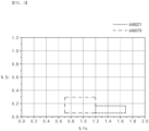
- FIG. 3 is a graph illustrating iron and silicon contents of an aluminum alloy having an alloy number AA8079 and an aluminum alloy having an alloy number AA8021.
- the aluminum alloy thin film forming the moisture barrier layer 1352 may have a grain size of 10 um to 13 um, preferably 10.5 um to 12.5 um, more preferably 11 um to 12 ⁇ m.
- an iron (Fe) content in the aluminum alloy thin film may be 1.2 wt% to 1.7 wt%, preferably 1.3 wt% to 1.7 wt%, more preferably 1.3 wt% to 1.45 wt%. If the iron (Fe) content in the aluminum alloy thin film is less than 1.2 wt%, the strength of the aluminum alloy thin film may be deteriorated to generate the cracks and pinholes during the molding. If the iron (Fe) content exceeds 1.7 wt%, the flexibility of the aluminum alloy thin film is deteriorated to cause a limitation in improving of the moldability.
- a silicon (Si) content in the aluminum alloy thin film may be 0.2 wt% or less, preferably 0.05 wt% to 0.2 wt%, more preferably 0.1 wt% to 0.2 wt%.
- the silicon content exceeds 0.2 wt%, the moldability may be deteriorated.
- the aluminum alloy thin film according to the present invention may be an aluminum alloy having the alloy number AA8021.
- the aluminum alloy thin film having the alloy number AA8079 was mainly used for the battery pouch according to the related art.
- the aluminum alloy having the alloy number AA8079 (hereinafter, referred to as an AA8079 aluminum alloy) contains 0.6 wt% to 1.2 wt% of iron, and 0.3 wt% or less of silicon.
- the aluminum alloy of alloy number AA8079 relatively little iron is included, and when the moisture barrier layer 1352 is manufactured using the same, the flexibility may be improved, but the strength may be deteriorated, and thus there may be a limitation in moldability.
- an AA8021 aluminum alloy may contains 1.2 wt% to 1.7 wt% of iron, and in particular, 1.3 wt% to 1.7 wt%, and 0.2 wt% or less of silicon.
- the moisture barrier layer 1352 since a relatively large amount of iron is contained, the tensile strength, the drawing rate, and the puncture strength may be improved.
- a relationship between the tensile strength and the drawing rate may be expressed as a graph.
- a vertical axis of the graph is the tensile strength
- a horizontal axis is the drawing rate
- a lower area of the graph is toughness of the corresponding material.
- the toughness refers to a degree of toughness against fracture of the material, and the more the toughness increases, the more the material is drawn until the material is not broken.
- the moisture barrier layer 1352 when the moisture barrier layer 1352 is manufactured using the AA8021 aluminum alloy, the tensile strength and the drawing rate may be improved, and thus, the toughness and the moldability may be improved.
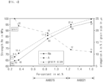
- FIG. 4 is a graph illustrating tensile strength, a drawing rate, and a grain size according to the iron and silicon contents of the AA8079 aluminum alloy and the AA8021 aluminum ally
- FIG. 5 is an enlarged SEM Image of crystal grains of the AA8079 aluminum alloy and the AA8021 aluminum ally.
- the tensile strength, the drawing rate, and the grain size are changed according to the iron content of the aluminum alloy. Particularly, since the tensile strength and the drawing rate are proportional to the iron content, the tensile strength and the drawing rate also increase as the iron content increases. On the other hand, since the grain size is inversely proportional to the iron content, the grain size decreases as the iron content increases.
- the AA8079 aluminum alloy has a relatively large grain size of 13 um to 21 um. Thus, there is a problem in that since internal stress is less dispersed when being drawn, and thus, the number of pinholes increases, the moldability of the battery case 13 is deteriorated.
- the AA8021 aluminum alloy has a relatively small grain size of 10 um to 13 um. Thus, since the internal stress is more dispersed when being drawn, the number of pinholes may decrease to improve the moldability of the battery case 13.
- the pouch film 135 according to the present invention may have a total thickness of 160 um to 200 um, preferably 180 ⁇ m to 200 um.
- the molding depth may increase while minimizing the reduction of the battery accommodation space and the deterioration of the sealing durability due to the increase in thickness of the pouch.
- the pouch film 135 according to the present invention has excellent tensile strength and drawing rate by including the aluminum alloy thin film having a specific thickness and grain size. Particularly, after the pouch film 135 according to the present invention is cut to a size of 15 mm X 80 mm, the tensile strength measured while being pulled at a tensile speed of 50 mm/min may be 200 N/15 mm to 300 N/15 mm, preferably 210 N/15 mm to 270 N/15 mm, more preferably 220 N/15 mm to 250 N/15 mm, and the drawing rate may be 120% to 150%, preferably 120% to 140%, more preferably 120% to 130%. As described above, the pouch film stack according to the present invention has the high tensile strength and drawing rate to increase in toughness. As a result, when the cup part is molded, the possibility of generation of the cracks is low even though the molding depth is deep.
- the pouch film stack according to the present invention has excellent puncture strength by including the aluminum alloy thin film having a specific thickness and grain size. Particularly, the pouch film stack according to the present invention may have puncture strength of 30 N or more .
- FIG. 6 is an enlarged schematic view of a die edge 138 and an electrode tab 11 according to Comparative Example of the present invention.
- a cup part 133 includes various types of edges, for example, includes a punch edge formed to correspond to a pressing edge 221 of a punch 22 and a die edge 138 formed to correspond to a pressing edge 213 of a die 21.
- the punch edge 139 connects each of a plurality of walls 1333 surrounding a periphery of the cup part 133 to a bottom part 1332, and the die edge 138 connects each of the plurality of walls 1333 to a side 134.
- the pressing edge of the die is not rounded, the pressing edge of the die is sharped, and thus, when the pouch film 135 is formed, stress is concentrated on the die edge of the cup part to easily cause cracks.
- the pressing edge 213 of the die 21 may be rounded so that the die edge 338 of the cup part 333 may be formed to be rounded to disperse the stress concentrated into the die edge somewhat.
- the depth of the cup part is formed to be greater than or equal to a certain depth, cracks may still occur in the pouch film 135 when the curvature radius of the die edge of the cup part is formed to be small (e.g., 2 mm or less).
- the specific depth may be approximately 7 mm based on the molding of one cup part 133 and approximately 6.5 mm based on the molding of two cup parts 133.
- the die edges 138 and 338 are formed to be rounded means that a curved surface is formed to have a curvature, and the curved surface may have a constant curvature on the whole, but is not limited thereto.
- the sealant layer 1351 may have a thickness of 60 um to 100 um, particularly 75 um to 85 um, and the moisture barrier layer 1352 may have a thickness of 50 um to 80 um, particularly 55 um to 65 um.
- the moisture barrier layer 1352 may be made of an aluminum alloy thin film having a grain size of 10 um to 13 ⁇ m.
- the wall 3333 of the cup part 333 may be close to the vertical state, and a curvature radius R3 of each of the edges 338 and 339 of the cup part 333 may be reduced.
- the cup part 333 when the pouch film 135 is drawing-molded, may be formed to have a depth less than or equal to the specific depth so that the wall 3333 of the cup part 333 is close to the vertical state, and the curvature radius R3 of each of the edges 338 and 339 of the cup part 333 is reduced.
- the wall 3333 of the cup part 333 may be formed to be close to the vertical side so as to have an inclination angle of 90° to 95°, preferably 90° to 93° from the bottom part 3332.
- at least one of the edges 338 and 339 of the cup part 133 may be rounded to have a curvature radius that corresponds to 1/20 to 1/6 of the depth of the cup part 333.
- the curvature radius R3 of 1 mm or less, particularly 0.7 mm or less, the cracks may be prevented from occurring.
- the electrode assembly 10 accommodated in the accommodation space 1331 may also increase in volume, and energy efficiency compared to the volume of the secondary battery 1 may also increase.
- the manufacturing costs may not increase significantly, the total thickness of the pouch may not increase significantly without reducing the thickness of the sealant layer 1351, and the sealing durability may not be deteriorated.
- each of the pouch type battery case 13 and the pouch type secondary battery 1 have a sharp shape on the whole, an outer appearance of the secondary battery 1 may be excellent, and marketability may be improved.
- the die edge 338 and the electrode tab ( 11) may interfere with each other.
- the electrode tab 11 since the electrode tab 11 protrudes from the electrodes stacked in the electrode assembly 10, the electrode tab 11 may be provided in plurality as many as the number of electrodes in the electrode assembly 10.
- the electrode tabs 11 are seated on the side 134.
- the electrode tabs 11 are seated from the die edge 338 to the side 134.
- the die edge 338 may be inserted toward the inside of the cup part 333, and also, flexibility at the die edge 338 may be deteriorated. Then, a distance between the die edge 338 and the electrode tabs 11 may be further reduced, and the die edge 338 may press the electrode tab 11 to cause the interference between the die edge 338 and the electrode tab 11. Particularly, as the number of electrode tabs 11 increases, the thickness of the stacked electrode tabs 11 is thicker, and thus, a space between the wall 3333 of the cup part 333 and the electrode tab 11 is narrowed. Thus, as the die edge 338 further presses the electrode tab 11, power may not be supplied smoothly, and even the electrode tab 11 may be disconnected.
- FIG. 7 is a partial plan view of the battery case 13 according to an embodiment of the present invention
- FIG. 8 is a partial plan view illustrating a state in which the electrode assembly 10 is inserted into the cup part 133 of the battery case 13 according to an embodiment of the present invention.
- the moldability of the pouch film 135 may be improved.
- the wall 1333 of the cup part 133 is close to the vertical state, and the curvature radii R1 and R2 of the die edge 138 of the cup part 133 is reduced, the edge 138 and the electrode tab 11 may be prevented from interfering with each other.
- the pouch type battery case 13 includes a cup part 133 accommodating an electrode assembly 10 formed by stacking electrodes and separators and a plurality of die edges 138 connecting an wall 1333 of the cup part 133 to a side 134 extending from the wall 1333 .
- At least one die edge 138 includes a first area 1381 formed to be rounded with a first curvature radius R1 (see FIG. 9 ) and a second area 1382 formed to be rounded with a second curvature radius R2 (see FIG. 10 ) that is less than the first curvature radius R1.
- the pouch type battery case 1 includes an electrode assembly 10 formed by stacking electrodes and separators and a battery case 13 including a cup part 133 accommodating the electrode assembly 10 therein.
- the battery case 13 includes a plurality of die edges 138 connecting an wall 1333 of the cup part 133 to a side 134 extending from the wall 1333.
- At least one die edge 138 includes a first area 1381 formed to be rounded with a first curvature radius R1 and a second area 1382 formed to be rounded with a second curvature radius R2 that is less than the first curvature radius R1.
- the battery case 13 includes the plurality of walls 1333 surrounding a periphery of the cup part 133 and the side 134 extending from the wall 1333.
- the die edge 138 connects each of the plurality of walls 1333 to the side 134.
- at least one die edge 138 is formed to be rounded with two different curvature radii R1 and R2. That is, as illustrated in FIG. 7 , at least one die edge 138 includes the first area 1381 formed to be rounded with the first curvature radius R1 and the second area 1382 formed to be rounded with the second curvature radius R2 less than the first curvature radius R1.
- the first curvature radius R1 may be 1.7 mm to 2.7 mm
- the second curvature radius R2 may be 1.2 mm or less, preferably 0.7 mm or less. That is, the first curvature radius R1 may be greater 1.5 times to 4 times than the second curvature radius R2.
- the first area 1381 is an area on which the electrode tab 11 protruding from one side of the electrode assembly 10 is seated.
- the second area 1382 is an area on which the electrode tab 11 is not seated.
- the first area 1381 is formed to be rounded with the relatively large first curvature radius R1
- the second area 1382 is formed to be rounded with the relatively small second curvature radius R2.
- a length of the first area 1381 may correspond to a width of the electrode tab 11 so that the electrode tab 11 is stably seated.
- the correspondence means that the length of the first area 1381 is equal to or slightly greater than the width of the electrode tab 11. If the length of the first area 1381 is less than the width of the electrode tab 11, the electrode tab 11 may not be stably seated on the die edge 138.
- the die edge 138 is formed along a circumference of the wall 1333 of the cup part 133, the die edge 138 is provided in plurality as many as the number of the walls 1333. For example, as illustrated in FIG. 7 , if the cup part 133 has a rectangular shape, four die edges 138 may be formed. However, the present invention is not limited thereto, and the number of die edges 138 may variously vary according to the number of walls 1333 of the cup part 133.
- the first area 1381 on which the electrode tab 11 is seated may also be formed on different die edge 138.
- one first area 1381 may be formed on each of two die edges 138 facing each other.
- the first area 1381 may be disposed approximately at a center of the die edge 138, and the second area 1382 may be formed on each of both sides of the first area 1381.
- the present invention is not limited thereto, and if the plurality of electrode tabs 11 protrude side by side from one side of the electrode assembly 10 in the same direction, the first area 1381 is formed in plurality on one die edge 138. In this case, the second area 1382 may be formed between the plurality of first areas 1381.
- first area 1381 and the second area 1382 are rounded with different curvature radii R1 and R2, a stepped portion may be formed between the first area 1381 and the second area 1382.
- connection area connecting the first area 1381 to the second area 1382 may be formed so that the stepped portion is not formed.
- the connection area may also be formed to be rounded and may be continuously changed from the first curvature radius R1 to the second curvature radius R2 while extending from the first area 1381 to the second area 1382.
- the first area 1381 and the second area 1382 may be continuously connected without forming the stepped portion therebetween.
- FIG. 9 is an enlarged schematic view of the first area 1381 of the die edge 138 and the electrode tab 11 according to an embodiment of the present invention
- FIG. 10 is an enlarged schematic view of the second area 1382 of the die edge 138 of the cup part 133 and the electrode tab 11 according to an embodiment of the present invention.
- the first area 1381 on which the electrode tab 11 is seated is rounded with the relatively large first curvature radius R1.
- the first curvature radius R1 may be 1.7 mm to 2.7 mm. Therefore, as illustrated in FIG. 9 , since the die edge 138 does not press the electrode tab 11, the die edge 138 and the electrode tab 11 may be prevented from interfering with each other on the first area 1381 on which the electrode tab 11 is seated.
- the second area 1382 on which the electrode tab 11 is not seated is rounded with the relatively small second curvature radius R2.
- the second curvature radius R2 may be 1.2 mm or less, preferably 0.7 mm or less.
- energy efficiency relative to the volume of the secondary battery 1 may also increase, and since each of the pouch type battery case 13 and the pouch type secondary battery 1 is manufactured in a sharp shape on the whole, the outer appearance of the secondary battery 1 may also be excellent, and the marketability may be improved.
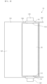
- FIG. 11 is a schematic view of a molding apparatus 2 according to an embodiment of the present invention.
- the molding apparatus 2 for molding the pouch film 135 includes a die 21, on which a pouch film 135 is seated on a top surface thereof and which includes at least one molding space 211 formed to be recessed inward from the top surface, and a punch 22 disposed above the molding space 211 and inserting the pouch film 135 into the molding space 211 while descending to mold the pouch film 135.
- the die 21 includes a plurality of pressing edges 213 connecting the molding space 211 to the top surface, and at least one pressing edge 213 includes a third area 2131 (see FIG. 12 ) formed to be rounded with a third curvature radius and a fourth area 2132 (see FIG. 12 ) formed to be rounded with a fourth curvature radius that is less than the third curvature radius.
- the two cup parts 133 may be drawing-molded to be adjacent to each other.
- two molding spaces 211 may be formed adjacent to each other in the die 21, and a partition wall 212 may be formed between the two molding spaces 211.
- one cup part may be formed in each of a first case 131 and a second case 132 to correspond to each of the two molding spaces 211, and thus, a total of two cup parts 133 are formed.
- a bridge 136 may also be formed between the two cup parts 133 to correspond to the partition wall 212.
- the bridge 136 may serve as a reference portion when the battery case 13 is folded later.
- the bridge 136 may form a folding part (not shown) at one side of the secondary battery 1. Since the folding part integrally connects the first case 131 and the second case 132 to each other, the number of sides 134 to be sealed may be reduced when a sealing process is performed later. Thus, a process rate may be improved, and the number of sealing processes may be reduced.
- a width of the folding part decreases, a space between the wall 1333 of the cup part 133 and the electrode assembly 10 may also decrease.
- the energy density relative to the volume may increase.
- the width of the folding part is proportional to a thickness of the bridge 136, and the bridge 136 is formed to correspond to the partition wall 212, the thickness of the bridge 136 is proportional to the thickness of the partition wall 212. Therefore, when the pouch film 135 is molded, the thickness of the bridge 136 may be minimized, and for this, the thickness of the partition wall 212 may be minimized.
- the partition wall 212 may be damaged in the drawing-molding process.
- the die 21 has the bottom, but in this case, when the punch 22 molds the pouch film 135, a gas existing in the space between the pouch film 135 and the molding space 211 may not be discharged.
- the bottom of the die 21 may be removed so that the gas existing in the space between the pouch film 135 and the molding space 211 is easily discharged, but the height of the partition wall 212 may be excessively high.
- an upper portion of the partition wall 212 may be maintained at a minimized thickness, and a reinforcing part 2121 that has a thickness greater than that of the partition wall 212 may be formed at a lower portion of the partition wall 212.
- the reinforcing part 2121 may be formed to be deeper than a depth D of the cup part 133 to be formed in the battery case 13 and may be formed at a position at which the partition wall 212 is not damaged.
- An exact position of the reinforcing part 2121 may be experimentally determined according to the thickness of the partition wall 212, a material of the partition wall 212, a pressure of the punch 22, and the depth D of the cup part 133 to be formed.
- the partition wall 212 may be formed to gradually increase in thickness toward the lower portion. That is, at least a portion of a cross-section of the partition wall 212 may have a substantially triangular shape, and an inner wall 214 of the molding space 211 formed in the partition wall 212 may have an inclination.
- the exact inclination of the inner wall 214 of the molding space 211 formed in the partition wall 212 may be experimentally determined by a thickness of an upper portion of the partition wall 212, the material of the partition wall 212, the pressure of the punch 22, and the depth of the cup part 133 to be formed. As a result, strength of the partition wall 212 may increase to prevent the partition wall 212 from being damaged in the drawing-molding process.
- FIG. 12 is a partial enlarged view of the die 21 according to an embodiment of the present invention.
- At least one die edge 138 of the pouch type battery case 13 includes the first area 1381 formed to be rounded with the first curvature radius R1 and the second area 1382 formed to be rounded with the second curvature radius R2 less than the first curvature radius R1.
- the die 21 in order to manufacture the battery case 13, includes the plurality of pressing edges 213 connecting the top surface thereof and the molding space 211 to each other, and at least one pressing edge 213 includes the third area 2131 that is rounded with the third curvature radius and the fourth area 2132 that is rounded with the fourth curvature radius that is less than the third curvature radius.
- the pouch film 135 is seated on the top surface of the die 21, particularly covers the molding space 211, and the punch 22 disposed above the molding space 211 descends to insert the pouch film 135 into the molding space 211 to mold the pouch film 135.
- the cup part 133 is formed, and the pouch type battery case 13 is manufactured.
- the die edge 138 of the pouch type battery case 13 is formed to correspond to the plurality of pressing edges 213 of the die 21.
- the third area 2131 of the pressing edge 213 corresponds to the first area 1381 of the battery case 13.
- the third curvature radius of the third area 2131 may be a value obtained by subtracting the thickness of the pouch film 135 from the first curvature radius R1 of the first area 1381.
- the first curvature radius R1 of the first area 1381 may be 1.7 mm to 2.7 mm, and thus the third curvature radius of the third area 2131 may range of 1.5 mm to 2.5 mm.
- the fourth area 2132 of the pressing edge 213 corresponds to the second area 1382 of the battery case 13.
- the fourth curvature radius of the second area 2132 may be a value obtained by subtracting the thickness of the pouch film 135 from the second curvature radius R2 of the second area 1382.
- the second curvature radius R2 of the second area 1382 may be 1.2 mm or less, preferably 0.7 mm or less
- the fourth curvature radius of the fourth area 2132 may be 1 mm or less, preferably may be 0.5 mm or less.
- the pressing edge 213 of the die 21 corresponds to the die edge 138 of the battery case 13, and the molding space 211 of the die 21 corresponds to the cup part 133 of the battery case 13.
- the pressing edge 213 is also formed along the circumference of the molding space 211, if the molding space 211 has a rectangular shape, four pressing edges 213 may be formed.
- the third area 2131 may also be formed on each of different pressing edges 213.
- one third area 2131 may be formed on each of two pressing edges 213 facing each other.
- the third area 2131 may be disposed approximately at a center of the pressing edge 213, and the second area 2132 may be formed on each of both sides of the first area 2131.
- the present invention is not limited thereto.
- the third area 2131 may be formed in plurality on one die edge 138, and the fourth area 2132 may be formed between the third areas 2131.
- a stepped portion may be formed between the third area 2131 and the fourth area 2132.
- the present invention is not limited thereto, and a connection area connecting the third area 2131 to the fourth area 2132 may be formed so that the stepped portion is not formed.
- the connection area may also be formed to be rounded and may be continuously changed from the third curvature radius to the fourth curvature radius while extending from the third area 2131 to the fourth area 2132.
- the third area 2131 and the fourth area 2132 may be continuously connected without forming the stepped portion therebetween.
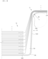
- FIG. 13 is a partial perspective view of a secondary battery 1 according to another embodiment of the present invention.
- At least one die edge 138 included in a battery case 13 may correspond to an electrode tab 11 (see FIG. 1 ) and include a first area 1381 that is concavely recessed inward.
- the at least one die edge 138 may further include a second area 1382 connected to the first area 1381 and formed to be less concave inward than the first area 1381.
- the first area 1381 may be more deeply recessed than the second area 1382, that is, toward a side 134.
- a protrusion or corner that interferes with the electrode tab 11 may not be formed in a width direction of the electrode tab 11, that is, in a length direction of the die edge 138.
- the electrode tab 11 and the second area 1382 may not interfere with each other .
- the first area 1381 has a length less than a width of the electrode tab 11
- the electrode tab 11 and the second area 1382 may not interfere with each other.
- the electrode tab 11 may not be excessively pressed by the first area 1381.
- first area 1381 and the second area 1382 may be formed to be rounded with different curvature radii, respectively. That is, a first curvature radius R1 of the first area 1381 may be greater than a second curvature radius R2 of the second area 1382.
Landscapes
- Chemical & Material Sciences (AREA)
- Chemical Kinetics & Catalysis (AREA)
- Electrochemistry (AREA)
- General Chemical & Material Sciences (AREA)
- Engineering & Computer Science (AREA)
- Mechanical Engineering (AREA)
- Sealing Battery Cases Or Jackets (AREA)
Abstract
Description
- This application claims the priority of
Korean Patent Application No. 10-2020-0129025 filed on October 06, 2020 Korean Patent Application No. 10-2021-0074479 filed on June 08, 2021 - The present invention relates to a pouch type battery case and an apparatus for molding the same, and a pouch type secondary battery, and more particularly, to a pouch type battery case, which is capable of preventing an interference between a die edge and an electrode tab from occurring, an apparatus for molding the same, and a pouch type secondary battery.
- In general, secondary batteries include nickel-cadmium batteries, nickel-hydrogen batteries, lithium ion batteries, and lithium ion polymer batteries. Such a secondary battery is being applied to be used in small-sized products such as digital cameras, P-DVDs, MP3Ps, mobile phones, PDAs, portable game devices, power tools, E-bikes, and the like as well as large-sized products requiring high power such as electric vehicles and hybrid vehicles, power storage devices for storing surplus power or renewable energy, and backup power storage devices.
- In general, in order to manufacture the secondary battery, first, electrode active material slurry is applied to a positive electrode collector and a negative electrode collector to manufacture a positive electrode and a negative electrode. Then, the electrodes are stacked on both sides of a separator to form an electrode assembly. Also, the electrode assembly is accommodated in a battery case, and then the battery case is sealed after an electrolyte is injected therein.
- Such a secondary battery is classified into a pouch type secondary battery and a can type secondary battery according to a material of a case accommodating the electrode assembly. In the pouch type secondary battery, an electrode assembly is accommodated in a pouch made of a flexible polymer material. Also, in the can type secondary battery, an electrode assembly is accommodated in a case made of a metal or plastic material.
- A pouch, which is a case of the pouch type secondary battery, is manufactured by forming a cup part by performing press processing on a pouch film having flexibility. In addition, when the cup part is formed, an electrode assembly is accommodated in an accommodation space of the cup part, and then, a side of the cup part is sealed to manufacture a secondary battery.
- In the press processing, drawing molding is performed by inserting a pouch film into a molding device such as a press equipment and applying a pressure to the pouch film by using a punch to draw the pouch film. The pouch film is provided as a plurality of layers, and a moisture barrier layer disposed in the pouch film is made of a metal. However, if the moisture barrier layer is improved in moldability so that an wall of the cup part is close to a vertical state, and a curvature radius of the edge of the cup part is improved, there is a problem that the die edge of edges presses electrode tabs to cause an interference between the die edge and the electrode tabs.
- (Patent Document 1)
Korea Patent Publication No. 2017-0124882 - An aspect of the present invention provides a pouch type battery case, which is capable of preventing an interference between a die edge and an electrode tab from occurring, an apparatus for molding the same, and a pouch type secondary battery.
- The objects of the present invention are not limited to the aforementioned object, but other objects not described herein will be clearly understood by those skilled in the art from descriptions below.
- According to an aspect of the present invention, there is provided a pouch type battery case including: a cup part configured to accommodate an electrode assembly, which is formed by stacking electrodes and separators, therein; and a plurality of die edges configured to connect an wall of the cup part to a side extending from the wall, wherein at least one die edge includes : a first area formed to be rounded with a first curvature radius; and a second area formed to be rounded with a second curvature radius less than the first curvature radius.
- The first curvature radius may be 1.7 mm to 2.7 mm.
- The second curvature radius may be 1.2 mm or less.
- The second curvature radius may be 0.7 mm or less.
- The pouch film may be molded to be manufactured, and the pouch film may include: a sealant layer made of a first polymer and formed at the innermost layer; a surface protection layer made of a second polymer and formed at the outermost layer; and a moisture barrier layer stacked between the surface protection layer and the sealant layer, wherein the moisture barrier layer may be formed as an aluminum alloy thin film having a thickness 50 um to 80 um and a grain size of 10 um to 13 um, and the sealant layer may have a thickness of 60 um to 100 µm.
- A specific depth may be 7 mm when one cup part is formed and may be 6.5 mm when two cup parts are formed.
- One first area may be formed on each of two die edges facing each other.
- The first area may be provided in plurality on one die edge.
- The second area may be formed between the plurality of first areas.
- According to another aspect of the present invention, there is provided a pouch type secondary battery including: an electrode assembly formed by stacking electrodes and separators; and a battery case comprising a cup part configured to accommodate the electrode assembly therein, wherein the battery case include a plurality of die edges configured to connect an wall of the cup part to a side extending from the wall, and at least one die edge includes: a first area formed to be rounded with a first curvature radius; and a second area formed to be rounded with a second curvature radius less than the first curvature radius.
- The electrode assembly may have a surface area of 15,000 mm2 to 100,000 mm2.
- An electrode tab protruding from one side of the electrode assembly may be seated on the first area.
- According to further another aspect of the present invention, there is provided an apparatus for molding a battery case, the apparatus including: a die, on which a pouch film is seated on a top surface thereof and which includes at least one molding space formed to be recessed inward from the top surface; and a punch disposed above the molding space and configured to insert the pouch film into the molding space while descending to mold the pouch film, wherein the die includes a plurality of pressing edges configured to connect the molding space to the top surface, and at least one pressing edge includes: a third area formed to be rounded with a third curvature radius; and a fourth area formed to be rounded with a fourth curvature radius that is less than the third curvature radius.
- The third curvature radius may be 1.5 mm to 2.5 mm.
- The fourth curvature radius may be 1 mm or less.
- According to further another aspect of the present invention, there is provided a pouch type secondary battery including: an electrode assembly formed by stacking electrodes and separators; and a battery case comprising a cup part configured to accommodate the electrode assembly therein, wherein the battery case includes a plurality of die edges configured to connect an wall of the cup part to a side extending from the wall, and at least one die edge corresponds to an electrode tab protruding from one side of the electrode assembly and includes a first area that is concavely recessed inward.
- The at least one die edge may further include a second area connected to the first area and formed to be less concave inward than the first area.
- The first area may be formed to be rounded with a first curvature radius, and the second area may be formed to be rounded with a second curvature radius that is less than the first curvature radius.
- Other particularities of the embodiments are included in the detailed description and drawings.
- According to the embodiments of the present invention, there are at least the following effects.
- In the die edge, the first area on which the electrode tab is seated may be formed to be rounded with a relatively large first curvature radius, and the second area on which the electrode tab is not seated may be formed to be rounded with a relatively small second curvature radius. Thus, even though the wall of the cup part is close to the vertical state, and the curvature radius of the die edge of the cup part is reduced, the interference between the die edge and the electrode tab may be prevented from occurring.
The effects of the prevent invention are not limited by the aforementioned description, and thus, more varied effects are involved in this specification. -
-
FIG. 1 is an assembled view of a secondary battery according to an embodiment of the present invention; -
FIG. 2 is a cross-sectional view of a pouch film according to an embodiment of the present invention; -
FIG. 3 is a graph illustrating iron and silicon contents of an aluminum alloy having an alloy number AA8079 and an aluminum alloy having an alloy number AA8021; -
FIG. 4 is a graph illustrating changes in tensile strength (Rm), drawing rate, and grain size according to the iron content of the aluminum alloy having the alloy number AA8079 and the aluminum alloy having the alloy number AA8021; -
FIG. 5 is an enlarged SEM Image of grains of the aluminum alloy having the alloy number AA8079 and the aluminum alloy having the alloy number AA8021; -
FIG. 6 is an enlarged schematic view of a die edge and an electrode tab according to Comparative Example of the present invention; -
FIG. 7 is a partial plan view of a battery case according to an embodiment of the present invention; -
FIG. 8 is a partial plan view illustrating a state in which an electrode assembly is inserted into a cup part of the battery case according to an embodiment of the present invention; -
FIG. 9 is an enlarged schematic view of a first area of the die edge and the electrode tab according to an embodiment of the present invention; -
FIG. 10 is an enlarged schematic view of a second area of the die edge of the cup part and the electrode tab according to an embodiment of the present invention; -
FIG. 11 is a schematic view of a molding apparatus according to an embodiment of the present invention; -
FIG. 12 is a partial enlarged view of a die according to an embodiment of the present invention; and -
FIG. 13 is a partial perspective view of a secondary battery according to another embodiment of the present invention. - Advantages and features of the present invention, and implementation methods thereof will be clarified through following embodiments described with reference to the accompanying drawings. The present invention may, however be embodied in different forms and should not be construed as limited to the embodiments set forth herein. Rather, these embodiments are provided so that this disclosure will be thorough and complete, and will fully convey the scope of the present invention to those skilled in the art. Further, the present invention is only defined by scopes of claims. Like reference numerals refer to like elements throughout.
- Unless terms used in the present invention are defined differently, all terms (including technical and scientific terms) used herein have the same meaning as generally understood by those skilled in the art. Also, unless defined clearly and apparently in the description, the terms as defined in a commonly used dictionary are not ideally or excessively construed as having formal meaning.
- In the following description, the technical terms are used only for explaining a specific exemplary embodiment while not limiting the present invention. In this specification, the terms of a singular form may include plural forms unless specifically mentioned. The meaning of "includes (comprises)" and/or "including (comprising)" does not exclude other components besides a mentioned component.
- Hereinafter, preferred embodiments will be described in detail with reference to the accompanying drawings.
-
FIG. 1 is an assembled view of asecondary battery 1 according to an embodiment of the present invention. - According to an embodiment of the present invention, as tensile strength and a drawing rate of a
pouch film 135 may be improved, toughness may increase to improve moldability when thepouch film 135 is molded to manufacture a pouchtype battery case 13. - For this, the
pouch film 135 according to an embodiment of the present invention includes a sealant layer 1351 (seeFIG. 2 ) made of a first polymer and formed at the innermost layer; a surface protection layer 1353 (seeFIG. 2 ) made of a second polymer and formed at the outermost layer; and a moisture (or gas) barrier layer 1352 (seeFIG. 2 ) stacked between thesurface protection layer 1353 and thesealant layer 1351. Themoisture barrier layer 1352 may be formed as an aluminum alloy thin film having a thickness of 50 um to 80 um and a grain size of 10 um to 13 um, and thesealant layer 1351 may have a thickness of 60 um to 100 um. Particularly, themoisture barrier layer 1352 may have a thickness of 55 um to 65 um, and thesealant layer 1351 may have a thickness of 75 um to 85 µm. - An
electrode assembly 10 is formed by alternately stacking electrodes and separators. First, slurry in which an electrode active material, a binder, and a plasticizer are mixed with each other is applied to a positive electrode collector and a negative electrode collector to manufacture the electrodes such as a positive electrode and a negative electrode . Then, respective separators are stacked between the electrodes to form theelectrode assembly 10, theelectrode assembly 10 is inserted into thebattery case 13, and an electrolyte is injected into thebattery case 13. - The
electrode assembly 10 may have a surface area of 15,000 mm2 to 100,000 mm2, which is obtained by multiplying a full length by a full width. In particular, the full width of theelectrode assembly 10 may be 60 mm or more. Also, theelectrode assembly 10 may have a thickness of 6 mm to 20 mm in a stacked direction. Therefore, theelectrode assembly 10 according to an embodiment of the present invention may provide a large battery capacity when compared to a general small-sized battery. - Particularly, the
electrode assembly 10 includes two types of electrodes such as the positive electrode and the negative electrode and the separator interposed between the electrodes to insulate the electrodes from each other. Theelectrode assembly 10 may be a stack type, a jelly roll type, a stacked and folding type, or the like. Each of the two types of electrodes, i.e., the positive electrode and the negative electrode has a structure in which active material slurry is applied to the electrode collector having a metal foil or metal mesh shape. The active material slurry may be usually formed by agitating a granular active material, a conductor, and the like in a state of adding a solvent. The solvent may be removed in the subsequent process. - As illustrated in
FIG. 1 , theelectrode assembly 10 includeselectrode tabs 11. Theelectrode tabs 11 are respectively connected to a positive electrode and a negative electrode of theelectrode assembly 10 to protrude outward from theelectrode assembly 10, thereby providing a path, through which electrons are moved, between the inside and outside of theelectrode assembly 10. An electrode collector of theelectrode assembly 10 is constituted by a portion coated with an electrode active material and a distal end, on which the electrode active material is not applied, i.e., a non-coating part. Also, each of anelectrode tabs 11 may be formed by cutting the non-coating part or by connecting a separate conductive member to the non-coating part through ultrasonic welding. As illustrated inFIG. 1 , theelectrode tabs 11 may protrude in each of different directions of theelectrode assembly 10, but is not limited thereto. For example, the electrode tabs may protrude in various directions, for example, protrude in parallel to each other from one side in the same direction. - In the
electrode assembly 10, anelectrode lead 12 that supplies electricity to the outside of thesecondary battery 1 is connected to theelectrode tab 11 through spot welding. Also, a portion of theelectrode lead 12 is surrounded by an insulatingpart 14. The insulatingpart 14 may be disposed to be limited to aside 134, at which afirst case 131 and asecond case 132 of thebattery case 13 are thermally fused, so that theelectrode lead 12 is bonded to thebattery case 13. Also, electricity generated from theelectrode assembly 10 may be prevented from flowing to thebattery case 13 through theelectrode lead 12, and the sealing of thebattery case 13 may be maintained. Thus, the insulatingpart 14 may be made of a nonconductor having non-conductivity, which is not electrically conductive. In general, although an insulation tape which is easily attached to theelectrode lead 12 and has a relatively thin thickness is mainly used as the insulatingpart 14, the present invention is not limited thereto. For example, various members may be used as the insulatingpart 14 as long as the members are capable of insulating theelectrode lead 12. - One end of the
electrode lead 12 is connected to theelectrode tab 11, and the other end of theelectrode lead 12 protrudes to the outside of thebattery case 13. That is, theelectrode lead 12 includes acathode lead 121 having one end connected to acathode tab 111 to extend in a direction in which thecathode tab 111 protrudes and ananode lead 122 having one end connected to ananode tab 112 to extend in a direction in which theanode tab 112 protrudes. On the other hand, as illustrated inFIG 1 , all of the other ends of thepositive electrode lead 121 and thenegative electrode lead 122 protrude to the outside of thebattery case 13. As a result, electricity generated in theelectrode assembly 10 may be supplied to the outside. Also, since each of thepositive electrode tab 111 and thenegative electrode tab 112 is formed to protrude in various directions, each of thepositive electrode lead 121 and thenegative electrode lead 122 may extend in various directions. - The
positive electrode lead 121 and thenegative electrode lead 122 may be made of materials different from each other. That is, thecathode lead 121 may be made of the same material as the cathode collector, i.e., an aluminum (Al) material, and theanode lead 122 may be made of the same material as the anode collector, i.e., a copper (Cu) material or a copper material coated with nickel (Ni). Also, a portion of theelectrode lead 12, which protrudes to the outside of thebattery case 13, may be provided as a terminal part and electrically connected to an external terminal. - The
battery case 13 is a pouch, which is manufactured by molding a flexible material and accommodates theelectrode assembly 10 therein. Hereinafter, the case in which thebattery case 13 is the pouch will be described. When apouch film 135 having flexibility is drawing-molded by using a punch 22 (seeFIG. 11 ) or the like, a portion of thepouch film 135 is drawn to form thecup part 133 including a pocket-shapedaccommodation space 1331, thereby manufacturing thebattery case 13. - The
battery case 13 accommodates theelectrode assembly 10 so that a portion of theelectrode lead 12 is exposed and then is sealed. As illustrated inFIG. 1 , thebattery case 13 includes thefirst case 131 and thesecond case 132. Theaccommodation space 1331 in which thecup part 133 is formed to accommodate theelectrode assembly 10 may be provided in thefirst case 131, and thesecond case 132 may cover an upper side of theaccommodation space 1331 so that theelectrode assembly 10 is not separated to the outside of thebattery case 13. As illustrated inFIG. 1 , one side of thefirst case 131 and one side of thesecond case 132 may be connected to each other. However, the present invention is not limited thereto. For example, thefirst case 131 and thesecond case 132 may be separately manufactured to be separated from each other. - When the
cup part 133 is molded in thepouch film 135, only onecup part 133 may be formed in onepouch film 135, but the present invention is not limited thereto. For example, two cup parts may be drawing-molded to be adjacent to each other in onepouch film 135. Then, as illustrated inFIG. 1 , thecup parts 133 are formed in thefirst case 131 and thesecond case 132, respectively. Here, each of thecup parts 133, which are respectively formed in thefirst case 131 and thesecond case 132, may have the same depth D, but is not limited thereto, and may have different depths D. - According to an embodiment of the present invention, the depth D of the
cup part 133 may be 3 mm or more, in particular, 6.5 mm or more. Therefore, thecup part 133 according to an embodiment of the present invention may accommodate theelectrode assembly 10 having a larger electrode capacity compared to a general small-sized battery. - After accommodating the
electrode assembly 10 in theaccommodation space 1331 provided in thecup part 133 of thefirst case 131, thebattery case 13 may be folded with respect to abridge 136 formed between the twocup parts 133 in thebattery case 13 so that the twocup parts 133 face each other. Then, thecup part 133 of thesecond case 132 also accommodates theelectrode assembly 10 from the upper side thereof. Accordingly, since the twocup parts 133 accommodate oneelectrode assembly 10, theelectrode assembly 10 having a thicker thickness may be accommodated when compared to a case in which onecup part 133 is provided. In addition, since thefirst case 131 and thesecond case 132 are integrally connected to each other by folding thebattery case 13, the number ofsides 134 to be sealed when a sealing process is performed later may be reduced. Thus, a process rate may be improved, and the number of sealing processes may be reduced. - The
battery case 13 may include thecup part 133, in which theaccommodation space 1331 accommodating theelectrode assembly 10 is provided, and adegassing part 137 formed at a side portion of thecup part 133 to discharge a gas generated in thecup part 133 through a degassing hole. When theelectrode assembly 10 is accommodated in thecup part 133 of thebattery case 13, and the electrolyte is injected, and then an activation process is performed, a gas is generated inside thebattery case 13, and thus, a degassing process for discharging the gas to the outside is performed. - When the
electrode lead 12 is connected to theelectrode tab 11 of theelectrode assembly 10, and the insulatingpart 14 is formed on a portion of theelectrode lead 12, theelectrode assembly 10 is accommodated in theaccommodation space 1331 provided in thecup part 133 of thefirst case 131, and thesecond case 132 covers the accommodation space from the upper side. Also, the electrolyte is injected into the accommodation space, and theside 134 extending to the outside of thecup part 133 of each of thefirst case 131 and thesecond case 132 is sealed. The electrolyte may move lithium ions generated by electrochemical reaction of the electrode during charging and discharging of thesecondary battery 1. The electrolyte may include a non-aqueous organic electrolyte that is a mixture of a lithium salt and a high-purity organic solvent or a polymer using a polymer electrolyte. Furthermore, the electrolyte may include a sulfide-based, oxide-based, or polymer-based solid electrolyte, and the solid electrolyte may have flexibility that is easily deformed by external force. The pouch typesecondary battery 1 may be manufactured through the above-described method. -
FIG. 2 is a cross-sectional view of apouch film 135 according to an embodiment of the present invention. - The pouch that is the
battery case 13 of the pouch typesecondary battery 1 according to an embodiment of the present invention may be manufactured by drawing thepouch film 135. That is, thepouch film 135 is drawn by using thepunch 22 or the like to form thecup part 133, thereby manufacturing thebattery case 13. According to an embodiment of the present invention, as illustrated inFIG. 2 , thepouch film 135 may include thesealant layer 1351, themoisture barrier layer 1352, and thesurface protection layer 1353, and further include adrawing assistance layer 1354 if necessary. - The
sealant layer 1351 may be made of the first polymer and be formed at the innermost layer to be in direct contact with theelectrode assembly 10. Here, the innermost layer represents a layer disposed at the last when oriented in a direction opposite to the direction in which theelectrode assembly 10 is disposed with respect to themoisture barrier layer 1352. Thebattery case 13 may be manufactured while a portion of thepouch film 135 is drawn to form thecup part 133 including theaccommodation space 1331 having the pocket shape when thepouch film 135 having the stacked structure as described above is drawing-molded by using thepunch 22 or the like. Also, when theelectrode assembly 10 is accommodated in theaccommodation space 1331, the electrolyte is injected. Thereafter, when thefirst case 131 and thesecond case 132 are in contact with each other so as to face each other, and thermal compression is applied to theside 134, thesealant layers 1351 are bonded to each other to seal the pouch. Here, since thesealant layer 1351 is in direct contact with theelectrode assembly 10, thesealant layer 1351 has to have insulating properties. Also, since thesealant layer 1351 is in contact with the electrolyte, thesealant layer 1351 has to have corrosion resistance. Also, since the inside of thebattery case 13 is completely sealed to prevent materials from moving between the inside and outside of thebattery case 13, high sealability has to be realized. That is, theside 134 in which thesealant layers 1351 are bonded to each other should have superior thermal bonding strength. In general, the first polymer forming thesealant layer 1351 may include one or more materials selected from the group consisting of polyethylene, polypropylene, polycarbonate, polyethylene terephthalate, polyvinyl chloride, acrylic polymer, polyacrylonitrile, polyimide, polyamide, cellulose, aramid, nylon, polyester, polyparaphenylene benzobisoxazole, polyarylate, teflon, and glass fiber. Particularly, a polyolefin-based resin such as polypropylene (PP) or polyethylene (PE) is used for thesealant layer 1351. Polypropylene (PP) is excellent in mechanical properties such as tensile strength, rigidity, surface hardness, abrasion resistance, and heat resistance and chemical properties such as corrosion resistance and thus is mainly used for manufacturing thesealant layer 1351. Furthermore, thesealant layer 1351 may be made of a casted polypropylene, an acid modified polypropylene, or a polypropylene-butylene-ethylene terpolymer. Here, the acid-treated polypropylene may be maleic anhydride polypropylene (MAH PP) . Also, thesealant layer 1351 may have a single layer structure made of one material or a composite layer structure in which two or more materials are respectively formed as layers. - According to an embodiment of the present invention, the
sealant layer 1351 may have a thickness of 60 um to 100 µm, and in particular, a thickness of 75 um to 85 um. If thesealant layer 1351 has a thickness less than 60 um, thesealant layer 1351 may be deteriorated in durability, for example, the inside may be broken during the sealing. Conversely, if the sealant layer has a thickness greater than 100 um, the total thickness of the pouch is excessively thick, and rather, the moldability may be deteriorated, or an energy density relative to a volume of the secondary battery may be reduced. When the thickness of thesealant layer 1351 is thin, an insulation breakdown voltage of thepouch film 135 may be lowered, and thus the insulation may be deteriorated. When the battery is manufactured using thepouch film 135 having the poor insulation, a defect rate may increase. - The
moisture barrier layer 1352 is stacked between thesurface protection layer 1353 and thesealant layer 1351 to secure mechanical strength of the pouch, block introduction and discharge of a gas or moisture outside thesecondary battery 1, and prevent the electrolyte from leaking. Themoisture barrier layer 1352 may be made of an aluminum alloy thin film. The aluminum alloy thin film may secure the mechanical strength having a predetermined level or more, but be light in weight. Thus, the aluminum alloy thin film may complement for electrochemical properties and secure heat dissipation due to theelectrode assembly 10 and the electrolyte. - More specifically, the aluminum alloy thin film according to an embodiment of the present invention may have a grain size of 10 um to 13 um, preferably 10.5 um to 12.5 µm, and more preferably 11 um to 12 um. When the grain size of the aluminum alloy thin film satisfies the above range, the molding depth may increase without causing pinholes or cracks when the cup part is molded.
- The aluminum alloy thin film may include one or two kinds or more selected from the group consisting of iron (Fe), copper (Cu), chromium (Cr), manganese (Mn), nickel (Ni), magnesium (Mg), and zinc (Zn) in addition to aluminum.
- In addition, according to an embodiment of the present invention, the
moisture barrier layer 1352 may have a thickness of 50 um to 80 um, in particular, 55 um to 65 µm. - According to the related art, the moisture barrier layer has a thickness less than 50 um to deteriorate the moldability. Thus, when the
pouch film 135 is drawing-molded, there is a limitation in forming the wall of the cup part, which is close to the vertical state when the cup part is formed to have a deep depth, and there is a limitation in reducing the curvature radius of the edge of the cup part. In addition, when the battery case undergoes an impact from the outside, the internal electrode assembly may be easily damaged due to the weak puncture strength. - Conversely, if the moisture barrier layer has a thickness greater than about 80 um, not only the manufacturing cost increases, but also the total thickness of the secondary battery is excessively thick to deteriorate the energy density relative to the volume of the secondary battery. If the thickness of the sealant layer is reduced to be thinner than 60 um in order to reduce the total thickness of the secondary battery, sealing durability may be deteriorated.
- However, when only the thickness of the aluminum alloy thin film increases, the molding depth may increase, but the pinholes or cracks may be generated in the aluminum alloy thin film after the molding to deteriorate the sealing durability.
- As a result of repeated research by the present inventors, when the aluminum alloy thin film having a specific grain size is applied as the material of the moisture barrier layer, and the thickness of each of the moisture barrier layer and the sealant layer is controlled within a specific range, it is found that the cup part is molded deeply, and the sealing durability is also be maintained excellently. Therefore, the present invention has been implemented.
- Particularly, the
moisture barrier layer 1352 according to the present invention includes an aluminum alloy thin film having a grain size of 10 um to 13 um, preferably 10.5 um to 12.5 µm, and more preferably 11 um to 12 um. When the grain size of the aluminum alloy thin film satisfies the above range, the molding depth may increase without causing the pinholes or cracks when the cup part is molded. When the grain size of the aluminum alloy thin film exceeds 13 um, the strength of the aluminum alloy thin film decreases, and the generation of the cracks or pinholes increases due to difficulty in dispersing internal stress during the drawing. When the grain size is less than 10 um, the flexibility of the aluminum alloy thin film is lowered, and there is a limitation in improving the moldability. - The grain size varies depending on a composition of the aluminum alloy thin film and a processing method of the aluminum alloy thin film. Here, a cross-section in thickness direction of the aluminum alloy thin film may be observed and measured using a scanning electron microscope (SEM). Particularly, in the present invention, the cross-section in the thickness direction of the aluminum alloy thin film may be acquired using the scanning electron microscope, and then, maximum diameters of the predetermined number of grains among the grains observed through an SEM image may be measured to evaluate a mean value of the maximum diameters as the grain size.
- The
surface protection layer 1353 is made of the second polymer and formed at the outermost layer to protect thesecondary battery 1 against external friction and collision and also electrically insulates theelectrode assembly 10 from the outside. Here, the outermost layer represents a layer disposed at the last when oriented in a direction opposite to the direction in which theelectrode assembly 10 is disposed with respect to themoisture barrier layer 1352. The second polymer forming thesurface protection layer 1353 may include one or more materials selected from the group consisting of polyethylene, polypropylene, polycarbonate, polyethylene terephthalate, polyvinyl chloride, acrylic polymer, polyacrylonitrile, polyimide, polyamide, cellulose, aramid, nylon, polyester, polyparaphenylene benzobisoxazole, polyarylate, teflon, and glass fiber. Particularly, a polymer such as polyethylene terephthalate (PET) having abrasion resistance and heat resistance may be used mainly. Also, thesurface protection layer 1353 may have a single layer structure made of one material or a composite layer structure in which two or more materials are respectively formed as layers. - According to an embodiment of the present invention, the
surface protection layer 1353 may have a thickness of 5 um to 25 um, in particular, 7 um to 12 um. If the thickness of thesurface protection layer 1352 is less than 5 um, external insulation may be deteriorated. Conversely, if the thickness of thesurface protection layer 1352 is greater than 25 um, the total thickness of the pouch may be thicker, and thus, the energy density relative to the volume of thesecondary battery 1 may be reduced. - Although PET is inexpensive, has excellent durability, and has excellent electrical insulation, the PET has poor bonding force with respect to aluminum, which is frequently used for the
moisture barrier layer 1352, and also, a behavior when the PET is drawn by applying stress may be different. Thus, when thesurface protection layer 1353 and themoisture barrier layer 1352 are directly bonded to each other, theprotection layer 1353 and themoisture barrier layer 1352 may be delaminated during the drawing molding. As a result, themoisture barrier layer 1352 is not uniformly drawn to cause the deterioration in moldability. - According to an embodiment of the present invention, the
battery case 13 may be made of a third polymer and further include thedrawing assistance layer 1354 that is stacked between thesurface protection layer 1353 and themoisture barrier layer 1352. Thedrawing assistance layer 1354 may be stacked between thesurface protection layer 1352 and themoisture barrier layer 1352 to prevent thesurface protection layer 1353 and themoisture barrier layer 1352 from being delaminated when thesurface protection layer 1352 and themoisture barrier layer 1352 are drawn. The third polymer forming thedrawing assistance layer 1354 may include one or more materials selected from the group consisting of polyethylene, polypropylene, polycarbonate, polyethylene terephthalate, polyvinyl chloride, acrylic polymer, polyacrylonitrile, polyimide, polyamide, cellulose, aramid, nylon, polyester, polyparaphenylene benzobisoxazole, polyarylate, teflon, and glass fiber. Particularly, since a nylon resin easily adheres to polyethylene terephthalate (PET) of thesurface protection layer 1352, and a behavior when being drawn is similar to that of an aluminum alloy of themoisture barrier layer 1352, the nylon resin may be mainly used. Also, thedrawing assistance layer 1354 may have a single layer structure made of one material or a composite layer structure in which two or more materials are respectively formed as layers. - In the related art, the
moisture barrier layer 1352 has a thickness of approximately 40 um, and thus thedrawing assistance layer 1354 had a significantly thin thickness of approximately 15 um. That is, a thickness ratio of the drawing assistance layer and the moisture barrier layer is 1:2.67, and a thickness rate of the moisture barrier layer was considerably high. However, as described above, according to an embodiment of the present invention, since themoisture barrier layer 1352 has a thickness of approximately 50 um to approximately 80 um, and in particular, a thickness of 55 um to 65 um, the moldability of themoisture barrier layer 1352 is improved. Here, in order to also improve the moldability of thedrawing assistance layer 1354, thedrawing assistance layer 1354 may have a thickness of 20 um to 50 µm, and in particular, a thickness of 25 um to 38 um. If thedrawing assistance layer 1354 has a thickness less than 20 um, the drawing assistance layer may not conform to the improved moldability of the moisture barrier layer and thus be damaged during the drawing. Conversely, if thesealant layer 1351 has a thickness greater than 50 um, the total thickness of the pouch is thick to increase in volume of the secondary battery and deteriorate in energy density. Particularly, according to an embodiment of the present invention, a thickness ratio of thedrawing assistance layer 1354 and themoisture barrier layer 1352 may be less than 1:2.5. That is, the thickness ratio of thedrawing assistance layer 1354 may more increase when compared to the thickness ratio of thedrawing assistance layer 1354 according to the related art. However, when the thickness of thedrawing assistance layer 1354 is excessively thick, the total thickness of the pouch is thicker, and thus, the thickness ratio may be greater than 1:1.5 in order to prevent the total thickness of the pouch from be excessively thicker. That is, the thickness ratio may be 1:1.5 to 1:2.5. -
FIG. 3 is a graph illustrating iron and silicon contents of an aluminum alloy having an alloy number AA8079 and an aluminum alloy having an alloy number AA8021. - As described above, the aluminum alloy thin film forming the
moisture barrier layer 1352 may have a grain size of 10 um to 13 um, preferably 10.5 um to 12.5 um, more preferably 11 um to 12 µm. - In addition, an iron (Fe) content in the aluminum alloy thin film may be 1.2 wt% to 1.7 wt%, preferably 1.3 wt% to 1.7 wt%, more preferably 1.3 wt% to 1.45 wt%. If the iron (Fe) content in the aluminum alloy thin film is less than 1.2 wt%, the strength of the aluminum alloy thin film may be deteriorated to generate the cracks and pinholes during the molding. If the iron (Fe) content exceeds 1.7 wt%, the flexibility of the aluminum alloy thin film is deteriorated to cause a limitation in improving of the moldability.
- In addition, a silicon (Si) content in the aluminum alloy thin film may be 0.2 wt% or less, preferably 0.05 wt% to 0.2 wt%, more preferably 0.1 wt% to 0.2 wt%. When the silicon content exceeds 0.2 wt%, the moldability may be deteriorated.
- Particularly, the aluminum alloy thin film according to the present invention may be an aluminum alloy having the alloy number AA8021.
- On the other hand, the aluminum alloy thin film having the alloy number AA8079 was mainly used for the battery pouch according to the related art.
- When the aluminum alloy contains a large amount of iron, mechanical strength is improved, and when the aluminum alloy contains a small amount of iron, flexibility is improved.
- As illustrated in
FIG. 3 , the aluminum alloy having the alloy number AA8079 (hereinafter, referred to as an AA8079 aluminum alloy) contains 0.6 wt% to 1.2 wt% of iron, and 0.3 wt% or less of silicon. In the case of the aluminum alloy of alloy number AA8079, relatively little iron is included, and when themoisture barrier layer 1352 is manufactured using the same, the flexibility may be improved, but the strength may be deteriorated, and thus there may be a limitation in moldability. - On the other hand, as illustrated in
FIG. 3 , an AA8021 aluminum alloy may contains 1.2 wt% to 1.7 wt% of iron, and in particular, 1.3 wt% to 1.7 wt%, and 0.2 wt% or less of silicon. In the case of manufacturing themoisture barrier layer 1352 using the AA8021 aluminum alloy, since a relatively large amount of iron is contained, the tensile strength, the drawing rate, and the puncture strength may be improved. - On the other hand, when tensile force is applied to any material, a relationship between the tensile strength and the drawing rate may be expressed as a graph. Here, if a vertical axis of the graph is the tensile strength, and a horizontal axis is the drawing rate, a lower area of the graph is toughness of the corresponding material. The toughness refers to a degree of toughness against fracture of the material, and the more the toughness increases, the more the material is drawn until the material is not broken.
- Thus, when the
moisture barrier layer 1352 is manufactured using the AA8021 aluminum alloy, the tensile strength and the drawing rate may be improved, and thus, the toughness and the moldability may be improved. -
FIG. 4 is a graph illustrating tensile strength, a drawing rate, and a grain size according to the iron and silicon contents of the AA8079 aluminum alloy and the AA8021 aluminum ally, andFIG. 5 is an enlarged SEM Image of crystal grains of the AA8079 aluminum alloy and the AA8021 aluminum ally. - As illustrated in
FIG 4 , the tensile strength, the drawing rate, and the grain size are changed according to the iron content of the aluminum alloy. Particularly, since the tensile strength and the drawing rate are proportional to the iron content, the tensile strength and the drawing rate also increase as the iron content increases. On the other hand, since the grain size is inversely proportional to the iron content, the grain size decreases as the iron content increases. - The AA8079 aluminum alloy has a relatively large grain size of 13 um to 21 um. Thus, there is a problem in that since internal stress is less dispersed when being drawn, and thus, the number of pinholes increases, the moldability of the
battery case 13 is deteriorated. - The AA8021 aluminum alloy has a relatively small grain size of 10 um to 13 um. Thus, since the internal stress is more dispersed when being drawn, the number of pinholes may decrease to improve the moldability of the
battery case 13. - The
pouch film 135 according to the present invention may have a total thickness of 160 um to 200 um, preferably 180 µm to 200 um. When the thickness of thepouch film 135 satisfies the above range, the molding depth may increase while minimizing the reduction of the battery accommodation space and the deterioration of the sealing durability due to the increase in thickness of the pouch. - The
pouch film 135 according to the present invention has excellent tensile strength and drawing rate by including the aluminum alloy thin film having a specific thickness and grain size. Particularly, after thepouch film 135 according to the present invention is cut to a size of 15mm X 80 mm, the tensile strength measured while being pulled at a tensile speed of 50 mm/min may be 200 N/15 mm to 300 N/15 mm, preferably 210 N/15 mm to 270 N/15 mm, more preferably 220 N/15 mm to 250 N/15 mm, and the drawing rate may be 120% to 150%, preferably 120% to 140%, more preferably 120% to 130%. As described above, the pouch film stack according to the present invention has the high tensile strength and drawing rate to increase in toughness. As a result, when the cup part is molded, the possibility of generation of the cracks is low even though the molding depth is deep. - In addition, the pouch film stack according to the present invention has excellent puncture strength by including the aluminum alloy thin film having a specific thickness and grain size. Particularly, the pouch film stack according to the present invention may have puncture strength of 30 N or more .
FIG. 6 is an enlarged schematic view of adie edge 138 and anelectrode tab 11 according to Comparative Example of the present invention. - A
cup part 133 includes various types of edges, for example, includes a punch edge formed to correspond to apressing edge 221 of apunch 22 and adie edge 138 formed to correspond to apressing edge 213 of adie 21. Thepunch edge 139 connects each of a plurality ofwalls 1333 surrounding a periphery of thecup part 133 to abottom part 1332, and thedie edge 138 connects each of the plurality ofwalls 1333 to aside 134. However, if the pressing edge of the die is not rounded, the pressing edge of the die is sharped, and thus, when thepouch film 135 is formed, stress is concentrated on the die edge of the cup part to easily cause cracks. - To solve this, as illustrated in
FIG. 6 , thepressing edge 213 of the die 21 may be rounded so that thedie edge 338 of thecup part 333 may be formed to be rounded to disperse the stress concentrated into the die edge somewhat. - However, when the depth of the cup part is formed to be greater than or equal to a certain depth, cracks may still occur in the
pouch film 135 when the curvature radius of the die edge of the cup part is formed to be small (e.g., 2 mm or less). For example, the specific depth may be approximately 7 mm based on the molding of onecup part 133 and approximately 6.5 mm based on the molding of twocup parts 133. - In the present specification, that the die edges 138 and 338 are formed to be rounded means that a curved surface is formed to have a curvature, and the curved surface may have a constant curvature on the whole, but is not limited thereto.
- Thus, according to an embodiment of the present invention, the
sealant layer 1351 may have a thickness of 60 um to 100 um, particularly 75 um to 85 um, and themoisture barrier layer 1352 may have a thickness of 50 um to 80 um, particularly 55 um to 65 um. Themoisture barrier layer 1352 may be made of an aluminum alloy thin film having a grain size of 10 um to 13 µm. - Thus, since the moldability of the
moisture barrier layer 1352 is improved, as illustrated inFIG. 6 , when thepouch film 135 is drawing-molded, while thecup part 333 is formed to have a depth greater than or equal to a specific depth, thewall 3333 of thecup part 333 may be close to the vertical state, and a curvature radius R3 of each of theedges cup part 333 may be reduced. - Alternatively, according to another embodiment of the present invention, when the
pouch film 135 is drawing-molded, thecup part 333 may be formed to have a depth less than or equal to the specific depth so that thewall 3333 of thecup part 333 is close to the vertical state, and the curvature radius R3 of each of theedges cup part 333 is reduced. - Particularly, the
wall 3333 of thecup part 333 may be formed to be close to the vertical side so as to have an inclination angle of 90° to 95°, preferably 90° to 93° from thebottom part 3332. In addition, at least one of theedges cup part 133 may be rounded to have a curvature radius that corresponds to 1/20 to 1/6 of the depth of thecup part 333. Particularly, even if at least one of theedges cup part 133 is rounded to have the curvature radius R3 of 1 mm or less, particularly 0.7 mm or less, the cracks may be prevented from occurring. - As the
battery case 13 is manufactured as described above, since theaccommodation space 1331 increases in volume, theelectrode assembly 10 accommodated in theaccommodation space 1331 may also increase in volume, and energy efficiency compared to the volume of thesecondary battery 1 may also increase. In addition, the manufacturing costs may not increase significantly, the total thickness of the pouch may not increase significantly without reducing the thickness of thesealant layer 1351, and the sealing durability may not be deteriorated. In addition, since each of the pouchtype battery case 13 and the pouch typesecondary battery 1 have a sharp shape on the whole, an outer appearance of thesecondary battery 1 may be excellent, and marketability may be improved. - However, as the
wall 3333 of thecup part 333 is close to the vertical state, and the curvature radius of each of theedges cup part 333 decreases, as illustrated inFIG. 6 , thedie edge 338 and the electrode tab ( 11) may interfere with each other. Particularly, since theelectrode tab 11 protrudes from the electrodes stacked in theelectrode assembly 10, theelectrode tab 11 may be provided in plurality as many as the number of electrodes in theelectrode assembly 10. In addition, after the plurality ofelectrode tabs 11 are stacked and connected to each other, theelectrode tabs 11 are seated on theside 134. Here, theelectrode tabs 11 are seated from thedie edge 338 to theside 134. Thus, as the curvature radius R3 of thedie edge 338 decreases, thedie edge 338 may be inserted toward the inside of thecup part 333, and also, flexibility at thedie edge 338 may be deteriorated. Then, a distance between thedie edge 338 and theelectrode tabs 11 may be further reduced, and thedie edge 338 may press theelectrode tab 11 to cause the interference between thedie edge 338 and theelectrode tab 11. Particularly, as the number ofelectrode tabs 11 increases, the thickness of the stackedelectrode tabs 11 is thicker, and thus, a space between thewall 3333 of thecup part 333 and theelectrode tab 11 is narrowed. Thus, as thedie edge 338 further presses theelectrode tab 11, power may not be supplied smoothly, and even theelectrode tab 11 may be disconnected. -
FIG. 7 is a partial plan view of thebattery case 13 according to an embodiment of the present invention, andFIG. 8 is a partial plan view illustrating a state in which theelectrode assembly 10 is inserted into thecup part 133 of thebattery case 13 according to an embodiment of the present invention. - According to embodiments of the present invention, the moldability of the
pouch film 135 may be improved. Thus, even though thewall 1333 of thecup part 133 is close to the vertical state, and the curvature radii R1 and R2 of thedie edge 138 of thecup part 133 is reduced, theedge 138 and theelectrode tab 11 may be prevented from interfering with each other. - For this, the pouch
type battery case 13 according to an embodiment of the present invention includes acup part 133 accommodating anelectrode assembly 10 formed by stacking electrodes and separators and a plurality ofdie edges 138 connecting anwall 1333 of thecup part 133 to aside 134 extending from thewall 1333 . At least onedie edge 138 includes afirst area 1381 formed to be rounded with a first curvature radius R1 (seeFIG. 9 ) and asecond area 1382 formed to be rounded with a second curvature radius R2 (seeFIG. 10 ) that is less than the first curvature radius R1. - In addition, the pouch
type battery case 1 according to an embodiment of the present invention includes anelectrode assembly 10 formed by stacking electrodes and separators and abattery case 13 including acup part 133 accommodating theelectrode assembly 10 therein. Thebattery case 13 includes a plurality ofdie edges 138 connecting anwall 1333 of thecup part 133 to aside 134 extending from thewall 1333. At least onedie edge 138 includes afirst area 1381 formed to be rounded with a first curvature radius R1 and asecond area 1382 formed to be rounded with a second curvature radius R2 that is less than the first curvature radius R1. - As described above, the
battery case 13 includes the plurality ofwalls 1333 surrounding a periphery of thecup part 133 and theside 134 extending from thewall 1333. In addition, thedie edge 138 connects each of the plurality ofwalls 1333 to theside 134. According to an embodiment of the present invention, at least onedie edge 138 is formed to be rounded with two different curvature radii R1 and R2. That is, as illustrated inFIG. 7 , at least onedie edge 138 includes thefirst area 1381 formed to be rounded with the first curvature radius R1 and thesecond area 1382 formed to be rounded with the second curvature radius R2 less than the first curvature radius R1. - Here, the first curvature radius R1 may be 1.7 mm to 2.7 mm, and the second curvature radius R2 may be 1.2 mm or less, preferably 0.7 mm or less. That is, the first curvature radius R1 may be greater 1.5 times to 4 times than the second curvature radius R2.
- As illustrated in
FIGS. 7 and8 , thefirst area 1381 is an area on which theelectrode tab 11 protruding from one side of theelectrode assembly 10 is seated. On the other hand, thesecond area 1382 is an area on which theelectrode tab 11 is not seated. Thus, thefirst area 1381 is formed to be rounded with the relatively large first curvature radius R1, and thesecond area 1382 is formed to be rounded with the relatively small second curvature radius R2. - A length of the
first area 1381 may correspond to a width of theelectrode tab 11 so that theelectrode tab 11 is stably seated. Here, the correspondence means that the length of thefirst area 1381 is equal to or slightly greater than the width of theelectrode tab 11. If the length of thefirst area 1381 is less than the width of theelectrode tab 11, theelectrode tab 11 may not be stably seated on thedie edge 138. - Since the
die edge 138 is formed along a circumference of thewall 1333 of thecup part 133, thedie edge 138 is provided in plurality as many as the number of thewalls 1333. For example, as illustrated inFIG. 7 , if thecup part 133 has a rectangular shape, four dieedges 138 may be formed. However, the present invention is not limited thereto, and the number ofdie edges 138 may variously vary according to the number ofwalls 1333 of thecup part 133. - In addition, if the plurality of
electrode tabs 11 protrude in different directions of theelectrode assembly 10, thefirst area 1381 on which theelectrode tab 11 is seated may also be formed ondifferent die edge 138. For example, as illustrated inFIG. 7 , onefirst area 1381 may be formed on each of two dieedges 138 facing each other. Here, thefirst area 1381 may be disposed approximately at a center of thedie edge 138, and thesecond area 1382 may be formed on each of both sides of thefirst area 1381. However, the present invention is not limited thereto, and if the plurality ofelectrode tabs 11 protrude side by side from one side of theelectrode assembly 10 in the same direction, thefirst area 1381 is formed in plurality on onedie edge 138. In this case, thesecond area 1382 may be formed between the plurality offirst areas 1381. - Since the
first area 1381 and thesecond area 1382 are rounded with different curvature radii R1 and R2, a stepped portion may be formed between thefirst area 1381 and thesecond area 1382. - However, the present invention is not limited thereto, and a connection area connecting the
first area 1381 to thesecond area 1382 may be formed so that the stepped portion is not formed. The connection area may also be formed to be rounded and may be continuously changed from the first curvature radius R1 to the second curvature radius R2 while extending from thefirst area 1381 to thesecond area 1382. Thus, thefirst area 1381 and thesecond area 1382 may be continuously connected without forming the stepped portion therebetween. -
FIG. 9 is an enlarged schematic view of thefirst area 1381 of thedie edge 138 and theelectrode tab 11 according to an embodiment of the present invention, andFIG. 10 is an enlarged schematic view of thesecond area 1382 of thedie edge 138 of thecup part 133 and theelectrode tab 11 according to an embodiment of the present invention. - As described above, the
first area 1381 on which theelectrode tab 11 is seated is rounded with the relatively large first curvature radius R1. - The first curvature radius R1 may be 1.7 mm to 2.7 mm. Therefore, as illustrated in
FIG. 9 , since thedie edge 138 does not press theelectrode tab 11, thedie edge 138 and theelectrode tab 11 may be prevented from interfering with each other on thefirst area 1381 on which theelectrode tab 11 is seated. - On the other hand, the
second area 1382 on which theelectrode tab 11 is not seated is rounded with the relatively small second curvature radius R2. The second curvature radius R2 may be 1.2 mm or less, preferably 0.7 mm or less. - Therefore, as illustrated in
FIG. 10 , energy efficiency relative to the volume of thesecondary battery 1 may also increase, and since each of the pouchtype battery case 13 and the pouch typesecondary battery 1 is manufactured in a sharp shape on the whole, the outer appearance of thesecondary battery 1 may also be excellent, and the marketability may be improved. -
FIG. 11 is a schematic view of amolding apparatus 2 according to an embodiment of the present invention. - The
molding apparatus 2 for molding thepouch film 135 according to an embodiment of the present invention includes a die 21, on which apouch film 135 is seated on a top surface thereof and which includes at least onemolding space 211 formed to be recessed inward from the top surface, and apunch 22 disposed above themolding space 211 and inserting thepouch film 135 into themolding space 211 while descending to mold thepouch film 135. Thedie 21 includes a plurality of pressingedges 213 connecting themolding space 211 to the top surface, and at least onepressing edge 213 includes a third area 2131 (seeFIG. 12 ) formed to be rounded with a third curvature radius and a fourth area 2132 (seeFIG. 12 ) formed to be rounded with a fourth curvature radius that is less than the third curvature radius. - When molding the
pouch film 135 using themolding apparatus 2, only onecup part 133 may be formed as described above, but the present invention is not limited thereto. For example, the twocup parts 133 may be drawing-molded to be adjacent to each other. For this, as illustrated inFIG. 6 , twomolding spaces 211 may be formed adjacent to each other in thedie 21, and apartition wall 212 may be formed between the twomolding spaces 211. When thepouch film 135 is drawing-molded while thepunch 22 is inserted into both themolding spaces 211, one cup part may be formed in each of afirst case 131 and asecond case 132 to correspond to each of the twomolding spaces 211, and thus, a total of twocup parts 133 are formed. Abridge 136 may also be formed between the twocup parts 133 to correspond to thepartition wall 212. - The
bridge 136 may serve as a reference portion when thebattery case 13 is folded later. When the manufacture of thesecondary battery 1 is completed, thebridge 136 may form a folding part (not shown) at one side of thesecondary battery 1. Since the folding part integrally connects thefirst case 131 and thesecond case 132 to each other, the number ofsides 134 to be sealed may be reduced when a sealing process is performed later. Thus, a process rate may be improved, and the number of sealing processes may be reduced. Here, as a width of the folding part decreases, a space between thewall 1333 of thecup part 133 and theelectrode assembly 10 may also decrease. Thus, since the entire volume of thesecondary battery 1 is reduced, the energy density relative to the volume may increase. - Since the width of the folding part is proportional to a thickness of the
bridge 136, and thebridge 136 is formed to correspond to thepartition wall 212, the thickness of thebridge 136 is proportional to the thickness of thepartition wall 212. Therefore, when thepouch film 135 is molded, the thickness of thebridge 136 may be minimized, and for this, the thickness of thepartition wall 212 may be minimized. - However, if the
partition wall 212 is formed to have an excessively high height in a thin state, thepartition wall 212 may be damaged in the drawing-molding process. Particularly, according to the related art, thedie 21 has the bottom, but in this case, when thepunch 22 molds thepouch film 135, a gas existing in the space between thepouch film 135 and themolding space 211 may not be discharged. - Therefore, recently, the bottom of the die 21 may be removed so that the gas existing in the space between the
pouch film 135 and themolding space 211 is easily discharged, but the height of thepartition wall 212 may be excessively high. - Therefore, according to an embodiment of the present invention, as illustrated in
FIG. 10 , an upper portion of thepartition wall 212 may be maintained at a minimized thickness, and a reinforcingpart 2121 that has a thickness greater than that of thepartition wall 212 may be formed at a lower portion of thepartition wall 212. The reinforcingpart 2121 may be formed to be deeper than a depth D of thecup part 133 to be formed in thebattery case 13 and may be formed at a position at which thepartition wall 212 is not damaged. An exact position of the reinforcingpart 2121 may be experimentally determined according to the thickness of thepartition wall 212, a material of thepartition wall 212, a pressure of thepunch 22, and the depth D of thecup part 133 to be formed. - However, the present invention is not limited thereto, and the
partition wall 212 may be formed to gradually increase in thickness toward the lower portion. That is, at least a portion of a cross-section of thepartition wall 212 may have a substantially triangular shape, and aninner wall 214 of themolding space 211 formed in thepartition wall 212 may have an inclination. The exact inclination of theinner wall 214 of themolding space 211 formed in thepartition wall 212 may be experimentally determined by a thickness of an upper portion of thepartition wall 212, the material of thepartition wall 212, the pressure of thepunch 22, and the depth of thecup part 133 to be formed. As a result, strength of thepartition wall 212 may increase to prevent thepartition wall 212 from being damaged in the drawing-molding process. -
FIG. 12 is a partial enlarged view of the die 21 according to an embodiment of the present invention. - According to embodiments of the present invention, at least one
die edge 138 of the pouchtype battery case 13 includes thefirst area 1381 formed to be rounded with the first curvature radius R1 and thesecond area 1382 formed to be rounded with the second curvature radius R2 less than the first curvature radius R1. - In addition, in order to manufacture the
battery case 13, the die 21 according to embodiments of the present invention includes the plurality of pressingedges 213 connecting the top surface thereof and themolding space 211 to each other, and at least onepressing edge 213 includes thethird area 2131 that is rounded with the third curvature radius and thefourth area 2132 that is rounded with the fourth curvature radius that is less than the third curvature radius. - The
pouch film 135 is seated on the top surface of the die 21, particularly covers themolding space 211, and thepunch 22 disposed above themolding space 211 descends to insert thepouch film 135 into themolding space 211 to mold thepouch film 135. As a result, thecup part 133 is formed, and the pouchtype battery case 13 is manufactured. Here, thedie edge 138 of the pouchtype battery case 13 is formed to correspond to the plurality of pressingedges 213 of thedie 21. - The
third area 2131 of thepressing edge 213 corresponds to thefirst area 1381 of thebattery case 13. Here, the third curvature radius of thethird area 2131 may be a value obtained by subtracting the thickness of thepouch film 135 from the first curvature radius R1 of thefirst area 1381. For example, if the thickness of thepouch film 135 is 0.2 mm, the first curvature radius R1 of thefirst area 1381 may be 1.7 mm to 2.7 mm, and thus the third curvature radius of thethird area 2131 may range of 1.5 mm to 2.5 mm. - In addition, the
fourth area 2132 of thepressing edge 213 corresponds to thesecond area 1382 of thebattery case 13. Here, the fourth curvature radius of thesecond area 2132 may be a value obtained by subtracting the thickness of thepouch film 135 from the second curvature radius R2 of thesecond area 1382. For example, the second curvature radius R2 of thesecond area 1382 may be 1.2 mm or less, preferably 0.7 mm or less, and the fourth curvature radius of thefourth area 2132 may be 1 mm or less, preferably may be 0.5 mm or less. - The
pressing edge 213 of the die 21 corresponds to thedie edge 138 of thebattery case 13, and themolding space 211 of the die 21 corresponds to thecup part 133 of thebattery case 13. Thus, since thepressing edge 213 is also formed along the circumference of themolding space 211, if themolding space 211 has a rectangular shape, fourpressing edges 213 may be formed. - In addition, the
third area 2131 may also be formed on each of differentpressing edges 213. For example, onethird area 2131 may be formed on each of twopressing edges 213 facing each other. Here, thethird area 2131 may be disposed approximately at a center of thepressing edge 213, and thesecond area 2132 may be formed on each of both sides of thefirst area 2131. However, the present invention is not limited thereto. For example, thethird area 2131 may be formed in plurality on onedie edge 138, and thefourth area 2132 may be formed between thethird areas 2131. - Since the
third area 2131 and thefourth area 2132 are rounded with different curvature radii, a stepped portion may be formed between thethird area 2131 and thefourth area 2132. However, the present invention is not limited thereto, and a connection area connecting thethird area 2131 to thefourth area 2132 may be formed so that the stepped portion is not formed. The connection area may also be formed to be rounded and may be continuously changed from the third curvature radius to the fourth curvature radius while extending from thethird area 2131 to thefourth area 2132. Thus, thethird area 2131 and thefourth area 2132 may be continuously connected without forming the stepped portion therebetween. -
FIG. 13 is a partial perspective view of asecondary battery 1 according to another embodiment of the present invention. - At least one
die edge 138 included in abattery case 13 according to this embodiment may correspond to an electrode tab 11 (seeFIG. 1 ) and include afirst area 1381 that is concavely recessed inward. The at least onedie edge 138 may further include asecond area 1382 connected to thefirst area 1381 and formed to be less concave inward than thefirst area 1381. - In more detail, when the
secondary battery 1 is viewed from the outside, thefirst area 1381 may be more deeply recessed than thesecond area 1382, that is, toward aside 134. Thus, a protrusion or corner that interferes with theelectrode tab 11 may not be formed in a width direction of theelectrode tab 11, that is, in a length direction of thedie edge 138. - That is, when the
electrode assembly 10 is accommodated in thebattery case 13, even though theelectrode tab 11 does not exactly correspond to thefirst area 1381 and is partially deviated toward thesecond area 1382, theelectrode tab 11 and thesecond area 1382 may not interfere with each other . For example, even though thefirst area 1381 has a length less than a width of theelectrode tab 11, theelectrode tab 11 and thesecond area 1382 may not interfere with each other. - Also, since the
first area 1381 is concavely recessed, theelectrode tab 11 may not be excessively pressed by thefirst area 1381. - Thus, even though the width of the
electrode tab 11 of theelectrode assembly 10 is changed, it is not necessary to change the molding apparatus. - Also, in this embodiment, the
first area 1381 and thesecond area 1382 may be formed to be rounded with different curvature radii, respectively. That is, a first curvature radius R1 of thefirst area 1381 may be greater than a second curvature radius R2 of thesecond area 1382. - Those with ordinary skill in the technical field of the present invention pertains will be understood that the present invention can be carried out in other specific forms without changing the technical idea or essential features. Therefore, the above-disclosed embodiments are to be considered illustrative and not restrictive. Accordingly, the scope of the present invention is defined by the appended claims rather than the foregoing description and the exemplary embodiments described therein. Various modifications made within the meaning of an equivalent of the claims of the invention and within the claims are to be regarded to be in the scope of the present invention.
-
1: secondary battery 2: molding apparatus 10: electrode assembly 11: electrode tab 12: electrode lead 13: battery case 14: insulating part 21: die 22: punch 111: positive electrode tab 112: negative electrode tab 121: positive electrode lead 122: negative electrode lead 131: first case 132: second case 133: cup part 134: side 135: pouch film 136: bridge 137: degassing part 138: die edge 139: punch edge 211: molding space 212: partition wall 213: pressing edges of die 221: pressing edges of punch 1331: accommodation space 1332: bottom part 1333: wall 1351: sealant layer 1352: moisture barrier layer 1353: surface protection layer 1354: drawing assistance layer 1381: first area 1382: second area 2121: reinforcing part 2131: third area 2132: fourth area
Claims (18)
- A pouch type battery case comprising:a cup part configured to accommodate an electrode assembly, which is formed by stacking electrodes and separators, therein; anda plurality of die edges configured to connect an wall of the cup part to a side extending from the wall,wherein at least one die edge comprises:a first area formed to be rounded with a first curvature radius; anda second area formed to be rounded with a second curvature radius less than the first curvature radius.
- The pouch type battery case of claim 1, wherein the first curvature radius is 1.7 mm to 2.7 mm.
- The pouch type battery case of claim 1, wherein the second curvature radius is 1.2 mm or less.
- The pouch type battery case of claim 3, wherein the second curvature radius is 0.7 mm or less.
- The pouch type battery case of claim 4, wherein pouch film is molded to be manufactured, and
the pouch film comprises:a sealant layer made of a first polymer and formed at innermost layer;a surface protection layer made of a second polymer and formed at outermost layer; anda moisture barrier layer stacked between the surface protection layer and the sealant layer,wherein the moisture barrier layer is formed as an aluminum alloy thin film having a thickness 50 µm to 80 µm and a grain size of 10 µm to 13 µm, andthe sealant layer has a thickness of 60 µm to 100 µm. - The pouch type battery case of claim 1, wherein a specific depth is 7 mm when one cup part is formed and is 6.5 mm when two cup parts are formed.
- The pouch type battery case of claim 1, wherein one first area is formed on each of two die edges facing each other.
- The pouch type battery case of claim 1, wherein the first area is provided in plurality on one die edge.
- The pouch type battery case of claim 8, wherein the second area is formed between the plurality of first areas.
- A pouch type secondary battery comprising:an electrode assembly formed by stacking electrodes and separators; anda battery case comprising a cup part configured to accommodate the electrode assembly therein,wherein the battery case comprises a plurality of die edges configured to connect an wall of the cup part to a side extending from the wall, andat least one die edge comprises:a first area formed to be rounded with a first curvature radius; anda second area formed to be rounded with a second curvature radius less than the first curvature radius.
- The pouch type secondary battery of claim 10, wherein the electrode assembly has a surface area of 15,000 mm2 to 100,000 mm2.
- The pouch type secondary battery of claim 10, wherein an electrode tab protruding from one side of the electrode assembly is seated on the first area.
- An apparatus for molding a battery case, comprising:a die, on which a pouch film is seated on a top surface thereof and which comprises at least one molding space formed to be recessed inward from the top surface; anda punch disposed above the molding space and configured to insert the pouch film into the molding space while descending to mold the pouch film,wherein the die comprises a plurality of pressing edges configured to connect the molding space to the top surface, andat least one pressing edge comprises:a third area formed to be rounded with a third curvature radius; anda fourth area formed to be rounded with a fourth curvature radius that is less than the third curvature radius.
- The apparatus of claim 13, wherein the third curvature radius is 1.5 mm to 2.5 mm.
- The apparatus of claim 13, wherein the fourth curvature radius is 1 mm or less.
- A pouch type secondary battery comprising:an electrode assembly formed by stacking electrodes and separators; anda battery case comprising a cup part configured to accommodate the electrode assembly therein,wherein the battery case comprises a plurality of die edges configured to connect an wall of the cup part to a side extending from the wall, andat least one die edge corresponds to an electrode tab protruding from one side of the electrode assembly and comprises a first area that is concavely recessed inward.
- The pouch type secondary battery of claim 16, wherein the at least one die edge further comprises a second area connected to the first area and formed to be less concave inward than the first area.
- The pouch type secondary battery of claim 17, wherein the first area is formed to be rounded with a first curvature radius, and
the second area is formed to be rounded with a second curvature radius that is less than the first curvature radius.
Applications Claiming Priority (3)
| Application Number | Priority Date | Filing Date | Title |
|---|---|---|---|
| KR20200129025 | 2020-10-06 | ||
| KR1020210074479A KR102552691B1 (en) | 2020-10-06 | 2021-06-08 | The Pouch Type Battery Case And The Apparatus For Forming Thereof, Pouch Type Secondary Battery |
| PCT/KR2021/013714 WO2022075750A1 (en) | 2020-10-06 | 2021-10-06 | Pouch-type battery case, molding apparatus thereof, and pouch-type secondary battery |
Publications (3)
| Publication Number | Publication Date |
|---|---|
| EP4203148A1 true EP4203148A1 (en) | 2023-06-28 |
| EP4203148A4 EP4203148A4 (en) | 2024-12-25 |
| EP4203148B1 EP4203148B1 (en) | 2026-03-25 |
Family
ID=80931683
Family Applications (1)
| Application Number | Title | Priority Date | Filing Date |
|---|---|---|---|
| EP21878001.3A Active EP4203148B1 (en) | 2020-10-06 | 2021-10-06 | Pouch-type battery case, apparatus for molding the same, and pouch type secondary battery thereof |
Country Status (5)
| Country | Link |
|---|---|
| US (1) | US11682808B2 (en) |
| EP (1) | EP4203148B1 (en) |
| JP (2) | JP7604634B2 (en) |
| CN (1) | CN116349064B (en) |
| WO (1) | WO2022075750A1 (en) |
Families Citing this family (3)
| Publication number | Priority date | Publication date | Assignee | Title |
|---|---|---|---|---|
| CN116097503A (en) | 2020-08-19 | 2023-05-09 | 株式会社 Lg新能源 | Soft package type battery case and soft package type secondary battery |
| WO2022039533A1 (en) * | 2020-08-19 | 2022-02-24 | 주식회사 엘지에너지솔루션 | Pouch type battery case and pouch type secondary battery |
| KR102791905B1 (en) | 2022-12-22 | 2025-04-08 | 주식회사 엘지에너지솔루션 | Pouch type battery case and pouch type secondary battery |
Family Cites Families (26)
| Publication number | Priority date | Publication date | Assignee | Title |
|---|---|---|---|---|
| JP4951812B2 (en) | 2001-01-11 | 2012-06-13 | ソニー株式会社 | Nonaqueous electrolyte battery and manufacturing method thereof |
| JP3751947B2 (en) * | 2003-03-14 | 2006-03-08 | Necラミリオンエナジー株式会社 | Film outer battery |
| JP4664614B2 (en) | 2004-04-05 | 2011-04-06 | 株式会社東芝 | Sealed battery |
| US20090081532A1 (en) * | 2007-09-21 | 2009-03-26 | David Aaron Kaplin | Electrochemical cell with improved internal contact |
| JP4776408B2 (en) | 2006-03-20 | 2011-09-21 | 三洋電機株式会社 | Laminated battery |
| KR101243560B1 (en) * | 2006-05-09 | 2013-03-20 | 삼성에스디아이 주식회사 | Pouch type Lithium Rechargeable Battery |
| KR100917736B1 (en) * | 2007-09-14 | 2009-09-15 | 삼성에스디아이 주식회사 | Battery Pouches and Pouch Type Batteries |
| JP2010232067A (en) * | 2009-03-27 | 2010-10-14 | Sanyo Electric Co Ltd | Laminated battery |
| JP5548827B2 (en) * | 2010-08-09 | 2014-07-16 | エルジー・ケム・リミテッド | Secondary battery with improved safety |
| JP5374742B2 (en) | 2010-10-27 | 2013-12-25 | 日新製鋼株式会社 | Laminate battery exterior material, laminate battery exterior material manufacturing method, and laminate battery manufacturing method |
| JP2013026173A (en) | 2011-07-26 | 2013-02-04 | Sanyo Electric Co Ltd | Laminate outer package battery |
| JP5988668B2 (en) * | 2012-04-18 | 2016-09-07 | 日立マクセル株式会社 | Battery stack |
| KR101403692B1 (en) | 2012-12-26 | 2014-06-05 | (주)오렌지파워 | Pouch for battery, and pouch type battery including the same |
| JP2015095433A (en) | 2013-11-14 | 2015-05-18 | 株式会社デンソー | Laminate pack battery |
| KR102198004B1 (en) * | 2014-02-12 | 2021-01-04 | 삼성에스디아이 주식회사 | Battery pack |
| CN106165143B (en) * | 2014-04-09 | 2020-07-07 | 凸版印刷株式会社 | Power storage device packaging material, power storage device, and manufacturing method of embossed packaging material |
| KR102553312B1 (en) | 2016-01-18 | 2023-07-07 | 에스케이온 주식회사 | Battery cell |
| CN205602398U (en) * | 2016-02-01 | 2016-09-28 | 东莞新能源科技有限公司 | Packaging film and secondary cell |
| KR102143366B1 (en) * | 2016-02-02 | 2020-08-12 | 주식회사 엘지화학 | Secondary Battery Cell Case Having Round Edge and Apparatus for Manufacturing the Same |
| CN205406573U (en) * | 2016-03-02 | 2016-07-27 | 宁德时代新能源科技股份有限公司 | Soft packet of secondary cell casing |
| KR102201640B1 (en) | 2016-05-03 | 2021-01-11 | 주식회사 엘지화학 | Manufacturing Apparatus for Battery Case Capable of Deeply Forming Mounting Portion for Electrode Assembly and Method Using the Same |
| US11638948B2 (en) * | 2016-12-06 | 2023-05-02 | Robert Bosch Battery Systems Llc | Electrochemical cell having wave corner sealed joints, and device and method for forming same |
| KR102087992B1 (en) * | 2017-01-11 | 2020-03-11 | 주식회사 엘지화학 | Pouch type secondary battery and Apparatus for forming Pouch film |
| KR102275545B1 (en) * | 2017-03-08 | 2021-07-12 | 에스케이이노베이션 주식회사 | Bettery cell and fabricating method of the same |
| KR20190098581A (en) * | 2018-02-14 | 2019-08-22 | 주식회사 엘지화학 | The Apparatus And The Method For Forming Pouch |
| KR102284606B1 (en) | 2018-04-03 | 2021-07-30 | 에스케이이노베이션 주식회사 | Pouch for secondary battery, Secondary battery and Battery module including the secondary battery |
-
2021
- 2021-10-06 JP JP2023520510A patent/JP7604634B2/en active Active
- 2021-10-06 US US17/495,386 patent/US11682808B2/en active Active
- 2021-10-06 EP EP21878001.3A patent/EP4203148B1/en active Active
- 2021-10-06 CN CN202180068682.8A patent/CN116349064B/en active Active
- 2021-10-06 WO PCT/KR2021/013714 patent/WO2022075750A1/en not_active Ceased
-
2024
- 2024-12-10 JP JP2024215292A patent/JP7779610B2/en active Active
Also Published As
| Publication number | Publication date |
|---|---|
| EP4203148B1 (en) | 2026-03-25 |
| US11682808B2 (en) | 2023-06-20 |
| JP2023539537A (en) | 2023-09-14 |
| JP7604634B2 (en) | 2024-12-23 |
| US20220109203A1 (en) | 2022-04-07 |
| EP4203148A4 (en) | 2024-12-25 |
| JP2025060659A (en) | 2025-04-10 |
| CN116349064B (en) | 2024-06-18 |
| CN116349064A (en) | 2023-06-27 |
| WO2022075750A1 (en) | 2022-04-14 |
| JP7779610B2 (en) | 2025-12-03 |
Similar Documents
| Publication | Publication Date | Title |
|---|---|---|
| CN215955369U (en) | Pouch film, pouch-type battery case, and pouch-type secondary battery | |
| CN215955368U (en) | Pouch type battery case and pouch type secondary battery | |
| KR102552691B1 (en) | The Pouch Type Battery Case And The Apparatus For Forming Thereof, Pouch Type Secondary Battery | |
| US11955648B2 (en) | Pouch-type battery case, apparatus for forming same, and pouch-type secondary battery | |
| EP4203148B1 (en) | Pouch-type battery case, apparatus for molding the same, and pouch type secondary battery thereof | |
| EP4094928B1 (en) | Apparatus and method for folding a side | |
| EP4201651A1 (en) | Apparatus for sealing battery case, and secondary battery manufactured using same | |
| US20230373138A1 (en) | Apparatus and Method for Molding Battery Case, and Battery Case | |
| EP4439839A1 (en) | Pouch-type battery case and lithium secondary battery comprising same | |
| EP4411943B1 (en) | Pouch-type battery case and secondary battery including the same | |
| CN116210118B (en) | Apparatus and method for molding battery casings and battery casings | |
| US12580252B2 (en) | Pouch-type battery case and pouch-type secondary battery | |
| US12620655B2 (en) | Pouch film laminate, pouch type battery case, and pouch type secondary battery | |
| EP4614688A1 (en) | Pouch film laminate and secondary battery | |
| KR20230091783A (en) | Pouch type battery case and secondary battery including the same |
Legal Events
| Date | Code | Title | Description |
|---|---|---|---|
| STAA | Information on the status of an ep patent application or granted ep patent |
Free format text: STATUS: THE INTERNATIONAL PUBLICATION HAS BEEN MADE |
|
| PUAI | Public reference made under article 153(3) epc to a published international application that has entered the european phase |
Free format text: ORIGINAL CODE: 0009012 |
|
| STAA | Information on the status of an ep patent application or granted ep patent |
Free format text: STATUS: REQUEST FOR EXAMINATION WAS MADE |
|
| 17P | Request for examination filed |
Effective date: 20230324 |
|
| AK | Designated contracting states |
Kind code of ref document: A1 Designated state(s): AL AT BE BG CH CY CZ DE DK EE ES FI FR GB GR HR HU IE IS IT LI LT LU LV MC MK MT NL NO PL PT RO RS SE SI SK SM TR |
|
| DAV | Request for validation of the european patent (deleted) | ||
| DAX | Request for extension of the european patent (deleted) | ||
| A4 | Supplementary search report drawn up and despatched |
Effective date: 20241125 |
|
| RIC1 | Information provided on ipc code assigned before grant |
Ipc: B29C 43/36 20060101ALI20241119BHEP Ipc: B65B 47/04 20060101ALI20241119BHEP Ipc: B32B 15/20 20060101ALI20241119BHEP Ipc: H01M 50/124 20210101ALI20241119BHEP Ipc: H01M 50/116 20210101AFI20241119BHEP |
|
| STAA | Information on the status of an ep patent application or granted ep patent |
Free format text: STATUS: EXAMINATION IS IN PROGRESS |
|
| 17Q | First examination report despatched |
Effective date: 20250811 |
|
| GRAP | Despatch of communication of intention to grant a patent |
Free format text: ORIGINAL CODE: EPIDOSNIGR1 |
|
| STAA | Information on the status of an ep patent application or granted ep patent |
Free format text: STATUS: GRANT OF PATENT IS INTENDED |
|
| INTG | Intention to grant announced |
Effective date: 20251126 |
|
| P01 | Opt-out of the competence of the unified patent court (upc) registered |
Free format text: CASE NUMBER: UPC_APP_0015357_4203148/2025 Effective date: 20251201 |
|
| GRAS | Grant fee paid |
Free format text: ORIGINAL CODE: EPIDOSNIGR3 |
|
| GRAA | (expected) grant |
Free format text: ORIGINAL CODE: 0009210 |
|
| STAA | Information on the status of an ep patent application or granted ep patent |
Free format text: STATUS: THE PATENT HAS BEEN GRANTED |
|
| AK | Designated contracting states |
Kind code of ref document: B1 Designated state(s): AL AT BE BG CH CY CZ DE DK EE ES FI FR GB GR HR HU IE IS IT LI LT LU LV MC MK MT NL NO PL PT RO RS SE SI SK SM TR |
|
| REG | Reference to a national code |
Ref country code: CH Ref legal event code: F10 Free format text: ST27 STATUS EVENT CODE: U-0-0-F10-F00 (AS PROVIDED BY THE NATIONAL OFFICE) Effective date: 20260325 Ref country code: GB Ref legal event code: FG4D |
|
| REG | Reference to a national code |
Ref country code: DE Ref legal event code: R096 Ref document number: 602021050818 Country of ref document: DE |
|
| REG | Reference to a national code |
Ref country code: IE Ref legal event code: FG4D |