EP4203122A1 - Electrode assembly and secondary battery including same - Google Patents
Electrode assembly and secondary battery including same Download PDFInfo
- Publication number
- EP4203122A1 EP4203122A1 EP21892394.4A EP21892394A EP4203122A1 EP 4203122 A1 EP4203122 A1 EP 4203122A1 EP 21892394 A EP21892394 A EP 21892394A EP 4203122 A1 EP4203122 A1 EP 4203122A1
- Authority
- EP
- European Patent Office
- Prior art keywords
- electrode
- separation membrane
- electrode assembly
- disposed
- coating layer
- Prior art date
- Legal status (The legal status is an assumption and is not a legal conclusion. Google has not performed a legal analysis and makes no representation as to the accuracy of the status listed.)
- Pending
Links
Images




Classifications
-
- H—ELECTRICITY
- H01—ELECTRIC ELEMENTS
- H01M—PROCESSES OR MEANS, e.g. BATTERIES, FOR THE DIRECT CONVERSION OF CHEMICAL ENERGY INTO ELECTRICAL ENERGY
- H01M10/00—Secondary cells; Manufacture thereof
- H01M10/42—Methods or arrangements for servicing or maintenance of secondary cells or secondary half-cells
-
- H—ELECTRICITY
- H01—ELECTRIC ELEMENTS
- H01M—PROCESSES OR MEANS, e.g. BATTERIES, FOR THE DIRECT CONVERSION OF CHEMICAL ENERGY INTO ELECTRICAL ENERGY
- H01M10/00—Secondary cells; Manufacture thereof
- H01M10/05—Accumulators with non-aqueous electrolyte
- H01M10/058—Construction or manufacture
- H01M10/0587—Construction or manufacture of accumulators having only wound construction elements, i.e. wound positive electrodes, wound negative electrodes and wound separators
-
- H—ELECTRICITY
- H01—ELECTRIC ELEMENTS
- H01M—PROCESSES OR MEANS, e.g. BATTERIES, FOR THE DIRECT CONVERSION OF CHEMICAL ENERGY INTO ELECTRICAL ENERGY
- H01M10/00—Secondary cells; Manufacture thereof
- H01M10/04—Construction or manufacture in general
- H01M10/0431—Cells with wound or folded electrodes
-
- H—ELECTRICITY
- H01—ELECTRIC ELEMENTS
- H01M—PROCESSES OR MEANS, e.g. BATTERIES, FOR THE DIRECT CONVERSION OF CHEMICAL ENERGY INTO ELECTRICAL ENERGY
- H01M50/00—Constructional details or processes of manufacture of the non-active parts of electrochemical cells other than fuel cells, e.g. hybrid cells
- H01M50/40—Separators; Membranes; Diaphragms; Spacing elements inside cells
- H01M50/409—Separators, membranes or diaphragms characterised by the material
-
- H—ELECTRICITY
- H01—ELECTRIC ELEMENTS
- H01M—PROCESSES OR MEANS, e.g. BATTERIES, FOR THE DIRECT CONVERSION OF CHEMICAL ENERGY INTO ELECTRICAL ENERGY
- H01M50/00—Constructional details or processes of manufacture of the non-active parts of electrochemical cells other than fuel cells, e.g. hybrid cells
- H01M50/40—Separators; Membranes; Diaphragms; Spacing elements inside cells
- H01M50/409—Separators, membranes or diaphragms characterised by the material
- H01M50/411—Organic material
- H01M50/414—Synthetic resins, e.g. thermoplastics or thermosetting resins
- H01M50/417—Polyolefins
-
- H—ELECTRICITY
- H01—ELECTRIC ELEMENTS
- H01M—PROCESSES OR MEANS, e.g. BATTERIES, FOR THE DIRECT CONVERSION OF CHEMICAL ENERGY INTO ELECTRICAL ENERGY
- H01M50/00—Constructional details or processes of manufacture of the non-active parts of electrochemical cells other than fuel cells, e.g. hybrid cells
- H01M50/40—Separators; Membranes; Diaphragms; Spacing elements inside cells
- H01M50/409—Separators, membranes or diaphragms characterised by the material
- H01M50/431—Inorganic material
- H01M50/434—Ceramics
-
- H—ELECTRICITY
- H01—ELECTRIC ELEMENTS
- H01M—PROCESSES OR MEANS, e.g. BATTERIES, FOR THE DIRECT CONVERSION OF CHEMICAL ENERGY INTO ELECTRICAL ENERGY
- H01M50/00—Constructional details or processes of manufacture of the non-active parts of electrochemical cells other than fuel cells, e.g. hybrid cells
- H01M50/40—Separators; Membranes; Diaphragms; Spacing elements inside cells
- H01M50/409—Separators, membranes or diaphragms characterised by the material
- H01M50/443—Particulate material
-
- H—ELECTRICITY
- H01—ELECTRIC ELEMENTS
- H01M—PROCESSES OR MEANS, e.g. BATTERIES, FOR THE DIRECT CONVERSION OF CHEMICAL ENERGY INTO ELECTRICAL ENERGY
- H01M50/00—Constructional details or processes of manufacture of the non-active parts of electrochemical cells other than fuel cells, e.g. hybrid cells
- H01M50/40—Separators; Membranes; Diaphragms; Spacing elements inside cells
- H01M50/409—Separators, membranes or diaphragms characterised by the material
- H01M50/449—Separators, membranes or diaphragms characterised by the material having a layered structure
-
- H—ELECTRICITY
- H01—ELECTRIC ELEMENTS
- H01M—PROCESSES OR MEANS, e.g. BATTERIES, FOR THE DIRECT CONVERSION OF CHEMICAL ENERGY INTO ELECTRICAL ENERGY
- H01M50/00—Constructional details or processes of manufacture of the non-active parts of electrochemical cells other than fuel cells, e.g. hybrid cells
- H01M50/40—Separators; Membranes; Diaphragms; Spacing elements inside cells
- H01M50/46—Separators, membranes or diaphragms characterised by their combination with electrodes
-
- H—ELECTRICITY
- H01—ELECTRIC ELEMENTS
- H01M—PROCESSES OR MEANS, e.g. BATTERIES, FOR THE DIRECT CONVERSION OF CHEMICAL ENERGY INTO ELECTRICAL ENERGY
- H01M50/00—Constructional details or processes of manufacture of the non-active parts of electrochemical cells other than fuel cells, e.g. hybrid cells
- H01M50/40—Separators; Membranes; Diaphragms; Spacing elements inside cells
- H01M50/463—Separators, membranes or diaphragms characterised by their shape
-
- H—ELECTRICITY
- H01—ELECTRIC ELEMENTS
- H01M—PROCESSES OR MEANS, e.g. BATTERIES, FOR THE DIRECT CONVERSION OF CHEMICAL ENERGY INTO ELECTRICAL ENERGY
- H01M50/00—Constructional details or processes of manufacture of the non-active parts of electrochemical cells other than fuel cells, e.g. hybrid cells
- H01M50/40—Separators; Membranes; Diaphragms; Spacing elements inside cells
- H01M50/463—Separators, membranes or diaphragms characterised by their shape
- H01M50/469—Separators, membranes or diaphragms characterised by their shape tubular or cylindrical
-
- H—ELECTRICITY
- H01—ELECTRIC ELEMENTS
- H01M—PROCESSES OR MEANS, e.g. BATTERIES, FOR THE DIRECT CONVERSION OF CHEMICAL ENERGY INTO ELECTRICAL ENERGY
- H01M50/00—Constructional details or processes of manufacture of the non-active parts of electrochemical cells other than fuel cells, e.g. hybrid cells
- H01M50/50—Current conducting connections for cells or batteries
- H01M50/531—Electrode connections inside a battery casing
- H01M50/533—Electrode connections inside a battery casing characterised by the shape of the leads or tabs
-
- H—ELECTRICITY
- H01—ELECTRIC ELEMENTS
- H01M—PROCESSES OR MEANS, e.g. BATTERIES, FOR THE DIRECT CONVERSION OF CHEMICAL ENERGY INTO ELECTRICAL ENERGY
- H01M10/00—Secondary cells; Manufacture thereof
- H01M10/05—Accumulators with non-aqueous electrolyte
- H01M10/052—Li-accumulators
- H01M10/0525—Rocking-chair batteries, i.e. batteries with lithium insertion or intercalation in both electrodes; Lithium-ion batteries
-
- Y—GENERAL TAGGING OF NEW TECHNOLOGICAL DEVELOPMENTS; GENERAL TAGGING OF CROSS-SECTIONAL TECHNOLOGIES SPANNING OVER SEVERAL SECTIONS OF THE IPC; TECHNICAL SUBJECTS COVERED BY FORMER USPC CROSS-REFERENCE ART COLLECTIONS [XRACs] AND DIGESTS
- Y02—TECHNOLOGIES OR APPLICATIONS FOR MITIGATION OR ADAPTATION AGAINST CLIMATE CHANGE
- Y02E—REDUCTION OF GREENHOUSE GAS [GHG] EMISSIONS, RELATED TO ENERGY GENERATION, TRANSMISSION OR DISTRIBUTION
- Y02E60/00—Enabling technologies; Technologies with a potential or indirect contribution to GHG emissions mitigation
- Y02E60/10—Energy storage using batteries
-
- Y—GENERAL TAGGING OF NEW TECHNOLOGICAL DEVELOPMENTS; GENERAL TAGGING OF CROSS-SECTIONAL TECHNOLOGIES SPANNING OVER SEVERAL SECTIONS OF THE IPC; TECHNICAL SUBJECTS COVERED BY FORMER USPC CROSS-REFERENCE ART COLLECTIONS [XRACs] AND DIGESTS
- Y02—TECHNOLOGIES OR APPLICATIONS FOR MITIGATION OR ADAPTATION AGAINST CLIMATE CHANGE
- Y02P—CLIMATE CHANGE MITIGATION TECHNOLOGIES IN THE PRODUCTION OR PROCESSING OF GOODS
- Y02P70/00—Climate change mitigation technologies in the production process for final industrial or consumer products
- Y02P70/50—Manufacturing or production processes characterised by the final manufactured product
Definitions
- lithium secondary batteries such as lithium ion batteries and lithium ion polymer batteries, which have advantages, such as high energy density, discharge voltage, and output stability.
- the secondary battery is classified into a cylindrical battery and a prismatic battery in which the electrode assembly is embedded in a cylindrical or prismatic metal can, and a pouch-type battery in which the electrode assembly is embedded in a pouch-type case of an aluminum laminate sheet.
- secondary batteries are classified according to the structure of the electrode assembly in which a positive electrode, a negative electrode, and a separation membrane interposed between the positive electrode and the negative electrode are stacked.
- the electrode assembly may include a jellyroll-type electrode assembly in which long sheet-shaped positive electrodes and negative electrodes are wound with a separation membrane interposed therebetween, and a stack-type electrode assembly in which a plurality of positive and negative electrodes, which have been cut into units of a predetermined size, are sequentially stacked with a separation membrane interposed therebetween.
- the jellyroll-type electrode assembly may be formed by winding a positive electrode and a negative electrode, and in this case, the positive electrode and the negative electrode are wound in the state where a separation membrane is interposed between the positive electrode and the negative electrode.
- contraction and expansion of the jellyroll-type electrode assembly occurs, and thus bending deformation of the end of the positive electrode in the center is caused, resulting in cracks and causing disconnection or short circuit and greatly impairing the safety of the secondary battery.
- An exemplary embodiment of the present invention provides an electrode assembly, including: a first electrode; a second electrode; and a separation membrane interposed between the first electrode and the second electrode, in which the first electrode, the second electrode, and the separation membrane are wound together to form a jellyroll structure, and in a center of the jellyroll structure, an auxiliary separation membrane disposed between the first electrode and the separation membrane is further included.
- Each of the separation membrane and the auxiliary separation membrane may include a base layer and a coating layer.
- An end of the first electrode may be in contact with the coating layer of the auxiliary separation membrane.
- the first electrode may be a positive electrode
- the second electrode may be a negative electrode
- the auxiliary separation membrane may be wound above 0.5 times and below 1.5 times of a circumference of a winding core in the jellyroll structure.
- the second electrode may include an active material layer formed on a current collector, an uncoated region on which the active material layer is not formed, and an electrode tab bonded to the uncoated region, and in the center of the jellyroll structure, an end of the first electrode may be disposed while being spaced apart from the electrode tab.
- the end of the first electrode may be spaced apart from the end of the electrode tab by 1/4 or more of a winding circumference.
- the coating layer may include ceramic particles including at least one selected from the group consisting of alumina, silica, TiO 2 , SiC, and MgAl 2 O 4 .
- the base layer may include any one selected from the group consisting of polyethylene (PE), polystyrene (PS), polypropylene (PP), and a copolymer of polyethylene (PE) and polypropylene (PP).
- PE polyethylene
- PS polystyrene
- PP polypropylene
- PP copolymer of polyethylene
- PE polypropylene
- the separation membrane may be disposed so that the coating layer faces the first electrode.
- the auxiliary separation membrane may be extended from the separation membrane and be formed integrally with the separation membrane.
- the separation membrane may include a separation membrane region disposed between the first electrode and the second electrode, and an auxiliary separation membrane region disposed between the separation membrane region and the first electrode.
- the separation membrane may include a base layer, and a coating layer formed on any one surface of the base layer, and the coating layers may be formed on surfaces opposite to each other in the separation membrane region and the auxiliary separation membrane region, .
- the coating layer positioned in the separation membrane region may be disposed to face the first electrode.
- the coating layer positioned in the auxiliary separation membrane region may be disposed to face the first electrode.
- Another exemplary embodiment of the present invention provides a secondary battery including the electrode assembly.
- the separation membrane in the portion corresponding to the end of the portion where the winding of the positive electrode starts in a double-layer structure in the electrode assembly, it is possible to prevent cracks of the negative electrode in a portion that is in contact with the end of the positive electrode to prevent disconnection or short circuits, thereby improving safety of the secondary battery.
- FIG. 1 is a perspective view of an electrode assembly according to an exemplary embodiment of the present invention
- FIG. 2 is an exploded perspective view illustrating the state before the electrode assembly of FIG. 1 is wound
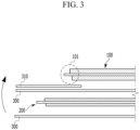
- FIG. 3 is a cross-sectional view of an end portion before the electrode assembly of FIG. 1 is wound.
- the electrode assembly includes a first electrode 100, a second electrode 200, and a separation membrane 300 interposed between the first electrode 100 and the second electrode 200, and the first electrode 100, the second electrode 200, and the separation membrane 300 are wound together to form a jelly-roll structure.
- the separation membrane 300 is additionally disposed under the second electrode 200 in order to prevent the contact between the first electrode 100 and the second electrode 200.
- an auxiliary separation membrane 310 is disposed between the innermost end 101 of the first electrode 100 and the separation membrane 300.
- the first electrode 100 may include an electrode current collector 120 made of a thin metal plate and an active material layer 130 formed on the electrode current collector 120.
- the active material layer 130 may be formed by applying an electrode active material to the electrode current collector 120.
- a first electrode tab 110 may be bonded.
- the second electrode 200 may include an electrode current collector 220 made of a thin metal plate and an active material layer 230 formed on the electrode current collector 220.
- the active material layer 230 may be formed by applying an electrode active material to the electrode current collector 220.
- a second electrode tab 210 may be bonded.
- the first electrode tab 110 and the second electrode tab 210 may protrude in opposite directions with respect to the electrode assembly of the jelly-roll structure.
- the first electrode 100 may be a positive electrode formed by applying a positive electrode active material to the electrode current collector 120
- the second electrode 200 may be a negative electrode formed by applying a negative electrode active material to the electrode current collector 220.
- the separation membrane 300 may be formed by coating a coating layer 301 including ceramic particles on a base layer 302.
- the auxiliary separation membrane 310 may also include the base layer 302 and a coating layer 301 formed thereon in the same manner as the separation membrane 300.
- the base layer 302 may include any one selected from the group consisting of polyethylene (PE), polystyrene (PS), polypropylene (PP), and a copolymer of polyethylene (PE) and polypropylene (PP).
- the coating layer 301 may include ceramic particles including at least one selected from the group consisting of alumina, silica, TiO 2 , SiC, and MgAl 2 O 4 .
- the coating layer 301 including such ceramic particles may be formed by applying a mixed slurry of the ceramic particles and a binder to the base layer 302.
- the foregoing coating layer 301 is included, so that the safety of the electrode assembly may be enhanced.
- all of the coating layers 301 may be disposed to face the first electrode 100 to prevent problems of cracks and overheating that may occur from the innermost end (edge) 101 of the first electrode 100 that is the positive electrode.
- the center C of the jellyroll structure is the center of the circular structure when the jellyroll structure is viewed from above, and refers to a virtual region corresponding to the part where the winding is started.
- the electrode assembly includes a rod-shaped winding core having a circular cross-section, and the jellyroll structure may be wound based on the winding core as a support, and the corresponding winding core may be removed from the center upon completion of winding.
- the innermost end 101 of the first electrode 100 refers to one end of the first electrode 100 at which winding starts first.
- the innermost end 101 of the first electrode 100 is in contact with the double separation membranes 300 and 310, it is possible to prevent the occurrence of cracks and overheating that may occur from the end of the first electrode 100. That is, as the design requirement of high energy density increases, the density increase of the first electrode 100, that is, the positive electrode, is unavoidable, and thus stress in a stepped portion of the positive electrode is increased.
- the stepped portion of the positive electrode is a portion in which a physical step is formed in the jellyroll electrode assembly as the thickness increases rapidly to 100 ⁇ m to 200 ⁇ m according to the interposition of the positive electrode at the start point of the positive electrode, and is the portion corresponding to the innermost end 101 of the first electrode 100 in the drawing.
- the stress is high, and therefore, when the corresponding portion is continuously pressed during the contraction and expansion process due to charging and discharging, the separation membrane at the portion which is in contact with the corresponding portion is damaged, and there is a high risk of ignition due to cracks and short circuits.
- the innermost end of the second electrode 200 may be located closer to the center C of the jellyroll structure than the innermost end 101 of the first electrode 100.
- the second electrode 200 which is the negative electrode
- the first electrode 100 which is the positive electrode
- the first electrode 100 may be interposed after the second electrode 200 is wound once or twice before the winding of the first electrode 100.
- the innermost end of the second electrode 200 may be located closer to the center C of the jellyroll structure than the innermost end 101 of the first electrode 100.
- the innermost end 101 of the first electrode 100 is preferably spaced apart from the end of the second electrode tab 210 along the winding circumference by 1/4 or more of the winding circumference. This means that in FIG. 5 , the distance from the end of the second electrode tab 210 to the innermost end 101 of the first electrode 100 is 1/4 or more of the winding circumference in the corresponding portion of the first electrode 100.
- the foregoing configuration may be obtained by adjusting the relative positions of the second electrode 200, the second electrode tab 210, and the first electrode 100 at the winding start point, that is, the center C, during winding.
- a portion of the separation membrane 300' forms a separation membrane region 300P disposed between a first electrode 100 and a second electrode 200, and the remaining portion forms an auxiliary separation membrane region 310P disposed between the separation membrane region 300P and the first electrode 100.
- the separation membrane region 300P and the auxiliary separation membrane region 310P form the integrally formed separation membrane 300', before being wound, as illustrated in FIG. 7 , the auxiliary separation membrane region 310P is folded to be located above the separation membrane region 300P, and the auxiliary separation membrane region 310P is disposed between the separation membrane region 300P and the first electrode 100.
- the separation membrane 300' includes a base layer 302 and a coating layer 301 similar to the foregoing exemplary embodiment, but the positions at which the coating layer 301 is disposed are located to be opposite to each other in the separation membrane region 300P and the auxiliary separation membrane region 310P. That is, as illustrated in FIG. 6 , in the auxiliary separation membrane region 310P, the coating layer 302 is formed on a surface opposite to the surface on which the coating layer 301 is formed in the separation membrane region 300P. With the foregoing configuration, even though the auxiliary separation membrane region 310P is disposed between the separation membrane region 300P and the first electrode 100 by folding as illustrated in FIG.
Landscapes
- Chemical & Material Sciences (AREA)
- Chemical Kinetics & Catalysis (AREA)
- Electrochemistry (AREA)
- General Chemical & Material Sciences (AREA)
- Engineering & Computer Science (AREA)
- Manufacturing & Machinery (AREA)
- Ceramic Engineering (AREA)
- Inorganic Chemistry (AREA)
- Secondary Cells (AREA)
Abstract
Description
- This application claims priority to and the benefit of
Korean Patent Application No. 10-2020-0152524 filed in the Korean Intellectual Property Office on November 16, 2020 Korean Patent Application No. 10-2021-0153233 filed in the Korean Intellectual Property Office on November 9, 2021 - The present invention relates to an electrode assembly and a secondary battery including the same, and more particularly, to an electrode assembly of a jelly-roll structure and a secondary battery including the same.
- Recently, due to the depletion of fossil fuels, the price of an energy source is increased and interest in environmental pollution is greatly increased, and the demand for an eco-friendly alternative energy source is becoming an essential factor for the future. Accordingly, research on various power production technologies, such as nuclear power, solar power, wind power, and tidal power, is continuing, and power storage devices for using the generated energy more efficiently are also of great interest.
- In particular, as technology development and demand for mobile devices increase, the demand for batteries as an energy source is rapidly increasing, and accordingly, a lot of research on batteries capable of meeting various needs is being conducted.
- Typically, there is a high demand for lithium secondary batteries, such as lithium ion batteries and lithium ion polymer batteries, which have advantages, such as high energy density, discharge voltage, and output stability.
- In addition, depending on the shape of the battery case, the secondary battery is classified into a cylindrical battery and a prismatic battery in which the electrode assembly is embedded in a cylindrical or prismatic metal can, and a pouch-type battery in which the electrode assembly is embedded in a pouch-type case of an aluminum laminate sheet.
- In addition, secondary batteries are classified according to the structure of the electrode assembly in which a positive electrode, a negative electrode, and a separation membrane interposed between the positive electrode and the negative electrode are stacked.
- Typically, the electrode assembly may include a jellyroll-type electrode assembly in which long sheet-shaped positive electrodes and negative electrodes are wound with a separation membrane interposed therebetween, and a stack-type electrode assembly in which a plurality of positive and negative electrodes, which have been cut into units of a predetermined size, are sequentially stacked with a separation membrane interposed therebetween.
- The jellyroll-type electrode assembly may be formed by winding a positive electrode and a negative electrode, and in this case, the positive electrode and the negative electrode are wound in the state where a separation membrane is interposed between the positive electrode and the negative electrode. However, as the charging/discharging cycle repeated hundreds to thousands of times proceeds, contraction and expansion of the jellyroll-type electrode assembly occurs, and thus bending deformation of the end of the positive electrode in the center is caused, resulting in cracks and causing disconnection or short circuit and greatly impairing the safety of the secondary battery.
- The problem to be solved by the present invention is to provide an electrode assembly capable of preventing cracks generable in an electrode during contraction and expansion of a secondary battery, and a secondary battery including the same.
- However, the problem to be solved in the exemplary embodiments of the present invention is not limited to the foregoing problem, and may be variously extended in the scope of the technical spirit included in the present invention.
- An exemplary embodiment of the present invention provides an electrode assembly, including: a first electrode; a second electrode; and a separation membrane interposed between the first electrode and the second electrode, in which the first electrode, the second electrode, and the separation membrane are wound together to form a jellyroll structure, and in a center of the jellyroll structure, an auxiliary separation membrane disposed between the first electrode and the separation membrane is further included.
- Each of the separation membrane and the auxiliary separation membrane may include a base layer and a coating layer.
- An end of the first electrode may be in contact with the coating layer of the auxiliary separation membrane.
- The first electrode may be a positive electrode, and the second electrode may be a negative electrode.
- The auxiliary separation membrane may be wound above 0.5 times and below 1.5 times of a circumference of a winding core in the jellyroll structure.
- The second electrode may include an active material layer formed on a current collector, an uncoated region on which the active material layer is not formed, and an electrode tab bonded to the uncoated region, and in the center of the jellyroll structure, an end of the first electrode may be disposed while being spaced apart from the electrode tab.
- In the center, the end of the first electrode may be spaced apart from the end of the electrode tab by 1/4 or more of a winding circumference.
- The coating layer may include ceramic particles including at least one selected from the group consisting of alumina, silica, TiO2, SiC, and MgAl2O4.
- The base layer may include any one selected from the group consisting of polyethylene (PE), polystyrene (PS), polypropylene (PP), and a copolymer of polyethylene (PE) and polypropylene (PP).
- The separation membrane may be disposed so that the coating layer faces the first electrode.
- The auxiliary separation membrane may be extended from the separation membrane and be formed integrally with the separation membrane.
- The separation membrane may include a separation membrane region disposed between the first electrode and the second electrode, and an auxiliary separation membrane region disposed between the separation membrane region and the first electrode.
- The separation membrane may include a base layer, and a coating layer formed on any one surface of the base layer, and the coating layers may be formed on surfaces opposite to each other in the separation membrane region and the auxiliary separation membrane region, .
- The coating layer positioned in the separation membrane region may be disposed to face the first electrode.
- The coating layer positioned in the auxiliary separation membrane region may be disposed to face the first electrode.
- Another exemplary embodiment of the present invention provides a secondary battery including the electrode assembly.
- According to the exemplary embodiments of the present invention, by forming the separation membrane in the portion corresponding to the end of the portion where the winding of the positive electrode starts in a double-layer structure in the electrode assembly, it is possible to prevent cracks of the negative electrode in a portion that is in contact with the end of the positive electrode to prevent disconnection or short circuits, thereby improving safety of the secondary battery.
- The effects of the present invention are not limited to the foregoing effects, and other non-mentioned effects will be clearly understood by those skilled in the art from the description below.
-
-
FIG. 1 is a perspective view of an electrode assembly according to an exemplary embodiment of the present invention. -
FIG. 2 is an exploded perspective view illustrating the state before the electrode assembly ofFIG. 1 is wound. -
FIG. 3 is a cross-sectional view of an end portion before the electrode assembly ofFIG. 1 is wound. -
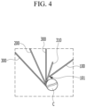
FIG. 4 is an enlarged view of a center of the electrode assembly when the electrode assembly is wound. -
FIG. 5 is a partial view of the enlarged center of the electrode assembly at the lower side ofFIG. 1 . -
FIG. 6 is a diagram illustrating a cross-section of a part of a separation membrane applied to an electrode assembly according to another exemplary embodiment of the present invention. -
FIG. 7 is a diagram illustrating a cross-section of an end portion before the electrode assembly is wound in the electrode assembly according to another exemplary embodiment to which the separation membrane ofFIG. 6 is applied. - In the following detailed description, only certain exemplary embodiments of the present invention have been shown and described, simply by way of illustration. However, the present invention can be variously implemented and is not limited to the following embodiments.
- Accordingly, the drawings and description are to be regarded as illustrative in nature and not restrictive. Like reference numerals designate like elements throughout the specification.
- In addition, the size and thickness of each configuration shown in the drawings are arbitrarily shown for understanding and ease of description, but the present invention is not limited thereto. In the drawings, the thickness of layers, films, panels, regions, etc., are exaggerated for clarity. In the drawings, for understanding and ease of description, the thickness of some layers and areas is exaggerated.
- Further, it will be understood that when an element such as a layer, film, region, or substrate is referred to as being "on" another element, it can be directly on the other element or intervening elements may also be present. In contrast, when an element is referred to as being "directly on" another element, there are no intervening elements present. Further, when an element is "on" a reference portion, the element is located above or below the reference portion, and it does not necessarily mean that the element is located "on" in a direction opposite to gravity.
- In addition, unless explicitly described to the contrary, the word "comprise", and variations such as "comprises" or "comprising", will be understood to imply the inclusion of stated elements but not the exclusion of any other elements.
- Further, in the entire specification, when it is referred to as "on a plane" it means when a target part is viewed from above, and when it is referred to as "on a cross-section", it means when the cross-section obtained by cutting a target part vertically is viewed from the side.
-
FIG. 1 is a perspective view of an electrode assembly according to an exemplary embodiment of the present invention,FIG. 2 is an exploded perspective view illustrating the state before the electrode assembly ofFIG. 1 is wound, andFIG. 3 is a cross-sectional view of an end portion before the electrode assembly ofFIG. 1 is wound. - Referring to
FIGS. 1 to 3 , the electrode assembly according to the exemplary embodiment of the present invention includes afirst electrode 100, asecond electrode 200, and aseparation membrane 300 interposed between thefirst electrode 100 and thesecond electrode 200, and thefirst electrode 100, thesecond electrode 200, and theseparation membrane 300 are wound together to form a jelly-roll structure. When the jelly-roll structure is formed, theseparation membrane 300 is additionally disposed under thesecond electrode 200 in order to prevent the contact between thefirst electrode 100 and thesecond electrode 200. Further, anauxiliary separation membrane 310 is disposed between theinnermost end 101 of thefirst electrode 100 and theseparation membrane 300. - The
first electrode 100 may include an electrodecurrent collector 120 made of a thin metal plate and anactive material layer 130 formed on theelectrode current collector 120. Theactive material layer 130 may be formed by applying an electrode active material to theelectrode current collector 120. In addition, after a portion of the electrodecurrent collector 120 is exposed without applying an active material, afirst electrode tab 110 may be bonded. - Similarly, the
second electrode 200 may include an electrodecurrent collector 220 made of a thin metal plate and anactive material layer 230 formed on the electrodecurrent collector 220. Theactive material layer 230 may be formed by applying an electrode active material to the electrodecurrent collector 220. In addition, after a portion of the electrodecurrent collector 220 is exposed without applying an active material, asecond electrode tab 210 may be bonded. - The
first electrode tab 110 and thesecond electrode tab 210 may protrude in opposite directions with respect to the electrode assembly of the jelly-roll structure. - Meanwhile, the
first electrode 100 may be a positive electrode formed by applying a positive electrode active material to the electrodecurrent collector 120, and thesecond electrode 200 may be a negative electrode formed by applying a negative electrode active material to the electrodecurrent collector 220. - The
separation membrane 300 may be formed by coating acoating layer 301 including ceramic particles on abase layer 302. Theauxiliary separation membrane 310 may also include thebase layer 302 and acoating layer 301 formed thereon in the same manner as theseparation membrane 300. For example, thebase layer 302 may include any one selected from the group consisting of polyethylene (PE), polystyrene (PS), polypropylene (PP), and a copolymer of polyethylene (PE) and polypropylene (PP). Thecoating layer 301 may include ceramic particles including at least one selected from the group consisting of alumina, silica, TiO2, SiC, and MgAl2O4. Thecoating layer 301 including such ceramic particles may be formed by applying a mixed slurry of the ceramic particles and a binder to thebase layer 302. In addition, the foregoingcoating layer 301 is included, so that the safety of the electrode assembly may be enhanced. As illustrated inFIG. 2 , all of the coating layers 301 may be disposed to face thefirst electrode 100 to prevent problems of cracks and overheating that may occur from the innermost end (edge) 101 of thefirst electrode 100 that is the positive electrode. - Hereinafter, with further reference to
FIGS. 4 and5 , the structure in the center (C) of the jellyroll structure will be described. -
FIG. 4 is an enlarged view of a center of the electrode assembly when the electrode assembly is wound, andFIG. 5 is a partial view of the enlarged center of the electrode assembly at the lower side ofFIG. 1 . In particular, inFIG. 5 , illustration of theseparation membrane 300 interposed between thefirst electrode 100 and thesecond electrode 200 is omitted for convenience of description. - Referring to
FIG. 4 and5 , in the jellyroll structure according to the present exemplary embodiment, theauxiliary separation membrane 310 is included between theinnermost end 101 of thefirst electrode 100 and theseparation membrane 300. At this time, both theauxiliary separation membrane 310 and the coating layer 301 (seeFIG. 2 ) included in theseparation membrane 300 are disposed to face thefirst electrode 100. Theinnermost end 101 of thefirst electrode 100 may be in contact with theauxiliary separation membrane 310. - Here, the center C of the jellyroll structure is the center of the circular structure when the jellyroll structure is viewed from above, and refers to a virtual region corresponding to the part where the winding is started. In the winding process, as illustrated in
FIG. 4 , the electrode assembly includes a rod-shaped winding core having a circular cross-section, and the jellyroll structure may be wound based on the winding core as a support, and the corresponding winding core may be removed from the center upon completion of winding. In addition, theinnermost end 101 of thefirst electrode 100 refers to one end of thefirst electrode 100 at which winding starts first. - As illustrated in
FIGS. 3 and4 , by configuring theinnermost end 101 of thefirst electrode 100 to be in contact with thedouble separation membranes first electrode 100. That is, as the design requirement of high energy density increases, the density increase of thefirst electrode 100, that is, the positive electrode, is unavoidable, and thus stress in a stepped portion of the positive electrode is increased. Here, the stepped portion of the positive electrode is a portion in which a physical step is formed in the jellyroll electrode assembly as the thickness increases rapidly to 100 µm to 200 µm according to the interposition of the positive electrode at the start point of the positive electrode, and is the portion corresponding to theinnermost end 101 of thefirst electrode 100 in the drawing. In the stepped portion of the positive electrode, the stress is high, and therefore, when the corresponding portion is continuously pressed during the contraction and expansion process due to charging and discharging, the separation membrane at the portion which is in contact with the corresponding portion is damaged, and there is a high risk of ignition due to cracks and short circuits. However, according to the exemplary embodiment of the present invention, as described above, since theinnermost end 101 of the first electrode is in contact with thedouble separation membranes - That is, as the repeated charge/discharge cycle proceeds hundreds to thousands of times, contraction and expansion of the electrode may occur, which causes bending deformation at the
innermost end 101 of thefirst electrode 100, and thus the crack of the electrode may be generated. However, the electrode assembly includes the double separation membrane including theauxiliary separation membrane 310 and thecoating layer 301 of theseparation membrane 300 and theauxiliary separation membrane 310 is disposed to face thefirst electrode 100, so that it is possible to prevent the occurrence of cracks and short circuits caused by the contraction and expansion of theinnermost end 101 of thefirst electrode 100 and ignition due to the crack and the short circuits. - The
auxiliary separation membrane 310 may be formed to have the same configuration as that of theseparation membrane 300, and may be wound up by 0.5 to 1.5 times of a circumference of a winding core in the jellyroll structure so as to be in contact with theinnermost end 101 of thefirst electrode 100. That is, when the winding core is located in the center C as illustrated inFIG. 4 , theauxiliary separation membrane 310 may be formed to wind a circumference of the winding core 0.5 to 1.5 times. Further, the present invention is not limited thereto, and the length of theauxiliary separation membrane 310 may be adjusted so as to wind the circumference of the winding core by 0.5 to 1.5 times while starting the winding from the innermost end portion of theauxiliary separation membrane 310. - In the meantime, based on the jellyroll structure, the innermost end of the
second electrode 200 may be located closer to the center C of the jellyroll structure than theinnermost end 101 of thefirst electrode 100. - In particular, in the center C of the jellyroll structure, the
second electrode 200 may be wound to extend beyond thefirst electrode 100. That is, after thesecond electrode 200 and theseparation membrane 300 are first wound to some extent, thefirst electrode 100 may be interposed so that thesecond electrode 200, theseparation membrane 300, and thefirst electrode 100 may be wound together. Thefirst electrode 100 and thesecond electrode 200 may be a positive electrode and a negative electrode, respectively, and in the chemical reaction of a lithium ion battery, since the negative electrode must receive lithium ions from the positive electrode, it is preferable that the negative electrode is designed to have a wider length and width than the positive electrode. When the length or width of the positive electrode is formed larger, the space to receive lithium ions is insufficient, so charging and discharging cannot be performed smoothly, and the risk of explosion may increase. Accordingly, it is preferable that thesecond electrode 200, which is the negative electrode, is wound before thefirst electrode 100, which is the positive electrode, at the center C where the winding of the jellyroll electrode assembly starts. For example, thefirst electrode 100 may be interposed after thesecond electrode 200 is wound once or twice before the winding of thefirst electrode 100. Accordingly, as described above, with respect to the jellyroll structure, the innermost end of thesecond electrode 200 may be located closer to the center C of the jellyroll structure than theinnermost end 101 of thefirst electrode 100. - In addition, as illustrated in
FIG. 5 , when viewed from the lower end of the electrode assembly, thesecond electrode tab 210 protruding outward may be spaced apart so as not to overlap theinnermost end 101 of thefirst electrode 100 in the center C. That is, thesecond electrode tab 210 is a portion electrically connected to the outside, and a lot of heat may be generated in the portion, and in this case, when theinnermost end 101 of thefirst electrode 100 comes into contact with thesecond electrode tab 210 having a high heat value, bending deformation stress and cracking probability due to contraction and expansion during repeated charge/discharge cycles are increased. However, as illustrated inFIG. 5 , thesecond electrode tab 210 and theinnermost end 101 of thefirst electrode 100 are disposed so as not to overlap each other, thereby reducing the risk occurrence probability. - In particular, to this end, the
innermost end 101 of thefirst electrode 100 is preferably spaced apart from the end of thesecond electrode tab 210 along the winding circumference by 1/4 or more of the winding circumference. This means that inFIG. 5 , the distance from the end of thesecond electrode tab 210 to theinnermost end 101 of thefirst electrode 100 is 1/4 or more of the winding circumference in the corresponding portion of thefirst electrode 100. As described above, by sufficiently separating theinnermost end 101 of thefirst electrode 100 from thesecond electrode tab 210, it is possible to prevent thesecond electrode tab 210 from being in contact with theinnermost end 101 of thefirst electrode 100, so that bending deformation stress and occurrence probability of cracks due to contraction and expansion when the charge/discharge cycle is repeated are lowered, thereby significantly reducing occurrence probability of internal short circuit or ignition. In addition, the foregoing configuration may be obtained by adjusting the relative positions of thesecond electrode 200, thesecond electrode tab 210, and thefirst electrode 100 at the winding start point, that is, the center C, during winding. - Next, another exemplary embodiment of the present invention will be described with reference to
FIGS. 6 and7 . -
FIG. 6 is a diagram illustrating a cross-section of a part of a separation membrane applied to an electrode assembly according to another exemplary embodiment of the present invention, andFIG. 7 is a diagram illustrating a cross-section of an end portion before the electrode assembly is wound in the electrode assembly according to another exemplary embodiment to which the separation membrane ofFIG. 6 is applied. - As illustrated in
FIGS. 6 and7 , in another exemplary embodiment of the present invention, a separation membrane 300' is folded so that an end is integrally extended from the separation membrane 300' becomes an auxiliary separation membrane. Except for this, other configurations are the same as those of the foregoing exemplary embodiment, so a description of the overlapping configuration will be omitted. - Referring to
FIGS. 6 and7 , in an electrode assembly according to another exemplary embodiment of the present invention, a portion of the separation membrane 300' forms aseparation membrane region 300P disposed between afirst electrode 100 and asecond electrode 200, and the remaining portion forms an auxiliaryseparation membrane region 310P disposed between theseparation membrane region 300P and thefirst electrode 100. Theseparation membrane region 300P and the auxiliaryseparation membrane region 310P form the integrally formed separation membrane 300', before being wound, as illustrated inFIG. 7 , the auxiliaryseparation membrane region 310P is folded to be located above theseparation membrane region 300P, and the auxiliaryseparation membrane region 310P is disposed between theseparation membrane region 300P and thefirst electrode 100. With the foregoing configuration, without providing an auxiliary separation membrane, the separation membrane is integrally extended and is folded to serve as an auxiliary separation membrane, the separation membrane in the portion which is in contact with the end of the positive electrode is formed in a double layer by a simpler structure, so that it is possible to prevent cracks of the negative electrode in the portion that is in contact with the end of the positive electrode to prevent short circuits, thereby improving safety of the secondary battery. - In this case, the separation membrane 300' includes a
base layer 302 and acoating layer 301 similar to the foregoing exemplary embodiment, but the positions at which thecoating layer 301 is disposed are located to be opposite to each other in theseparation membrane region 300P and the auxiliaryseparation membrane region 310P. That is, as illustrated inFIG. 6 , in the auxiliaryseparation membrane region 310P, thecoating layer 302 is formed on a surface opposite to the surface on which thecoating layer 301 is formed in theseparation membrane region 300P. With the foregoing configuration, even though the auxiliaryseparation membrane region 310P is disposed between theseparation membrane region 300P and thefirst electrode 100 by folding as illustrated inFIG. 7 , the coating layers of the auxiliaryseparation membrane region 310P and theseparation membrane region 300P may be disposed to face the positive electrode, that is, thefirst electrode 100. Accordingly, even in the electrode assembly according to another exemplary embodiment of the present invention, it is possible to effectively prevent cracks and short circuits caused by contraction and expansion of theinnermost end 101 of thefirst electrode 100, and ignition due to the cracks and the short circuits. - In the present exemplary embodiment, terms indicating directions, such as front, rear, left, right, up, and down, are used, but these terms are for convenience of explanation only, and may vary depending on the location of the object or the position of the observer.
- The electrode assembly according to the present exemplary embodiment described above may be accommodated in a battery case together with an electrolyte to form a secondary battery, and the secondary battery may be applied to various devices. Specifically, the electrode assembly may be applied to transportation means, such as an electric bicycle, an electric vehicle, and a hybrid vehicle, but is not limited thereto, and the electrode assembly may be applied to various devices that can use a secondary battery.
- Although an exemplary embodiment of the present invention has been described in detail, the scope of the present invention is not limited by the embodiment. Various changes and modifications using the basic concept of the present invention defined in the accompanying claims by those skilled in the art shall be construed to belong to the scope of the present invention.
-
- 100: First electrode
- 200: Second electrode
- 300: Separation membrane
- 310: Auxiliary separation membrane
- 301: Coating layer
Claims (16)
- An electrode assembly, comprising:a first electrode;a second electrode; anda separation membrane interposed between the first electrode and the second electrode,wherein the first electrode, the second electrode, and the separation membrane are wound together to form a jellyroll structure, andin a center of the jellyroll structure, an auxiliary separation membrane disposed between the first electrode and the separation membrane is further included.
- The electrode assembly of claim 1, wherein:
each of the separation membrane and the auxiliary separation membrane includes a base layer and a coating layer. - The electrode assembly of claim 2, wherein:
an end of the first electrode is in contact with the coating layer of the auxiliary separation membrane. - The electrode assembly of claim 1, wherein:
the first electrode is a positive electrode, and the second electrode is a negative electrode. - The electrode assembly of claim 1, wherein:
the auxiliary separation membrane is wound above 0.5 times and below 1.5 times of a circumference of a winding core in the jellyroll structure. - The electrode assembly of claim 1, wherein:the second electrode includes an active material layer formed on a current collector, an uncoated region on which the active material layer is not formed, and an electrode tab bonded to the uncoated region, andin the center of the jellyroll structure, an end of the first electrode is disposed while being spaced apart from the electrode tab.
- The electrode assembly of claim 6, wherein:
in the center, the end of the first electrode is spaced apart from the end of the electrode tab by 1/4 or more of a winding circumference. - The electrode assembly of claim 2, wherein:
the coating layer includes ceramic particles including at least one selected from the group consisting of alumina, silica, TiO2, SiC, and MgAl2O4. - The electrode assembly of claim 2, wherein:
the base layer includes any one selected from the group consisting of polyethylene (PE), polystyrene (PS), polypropylene (PP), and a copolymer of polyethylene (PE) and polypropylene (PP). - The electrode assembly of claim 2, wherein:
the separation membrane is disposed so that the coating layer faces the first electrode. - The electrode assembly of claim 1, wherein:
the auxiliary separation membrane is extended from the separation membrane and is formed integrally with the separation membrane. - The electrode assembly of claim 11, wherein:
the separation membrane includes a separation membrane region disposed between the first electrode and the second electrode, and an auxiliary separation membrane region disposed between the separation membrane region and the first electrode. - The electrode assembly of claim 12, wherein:the separation membrane includes a base layer, and a coating layer formed on any one surface of the base layer, andthe coating layers are formed on surfaces opposite to each other in the separation membrane region and the auxiliary separation membrane region.
- The electrode assembly of claim 13, wherein:
the coating layer positioned in the separation membrane region is disposed to face the first electrode. - The electrode assembly of claim 13, wherein:
the coating layer positioned in the auxiliary separation membrane region is disposed to face the first electrode. - A secondary battery comprising the electrode assembly of claim 1.
Applications Claiming Priority (3)
| Application Number | Priority Date | Filing Date | Title |
|---|---|---|---|
| KR20200152524 | 2020-11-16 | ||
| KR1020210153233A KR102828109B1 (en) | 2020-11-16 | 2021-11-09 | Electrode assembly and secondary battery including the same |
| PCT/KR2021/016661 WO2022103227A1 (en) | 2020-11-16 | 2021-11-15 | Electrode assembly and secondary battery including same |
Publications (2)
| Publication Number | Publication Date |
|---|---|
| EP4203122A1 true EP4203122A1 (en) | 2023-06-28 |
| EP4203122A4 EP4203122A4 (en) | 2024-11-20 |
Family
ID=81602532
Family Applications (1)
| Application Number | Title | Priority Date | Filing Date |
|---|---|---|---|
| EP21892394.4A Pending EP4203122A4 (en) | 2020-11-16 | 2021-11-15 | ELECTRODE ASSEMBLY AND SECONDARY BATTERY COMPRISING IT |
Country Status (5)
| Country | Link |
|---|---|
| US (1) | US20230369656A1 (en) |
| EP (1) | EP4203122A4 (en) |
| CN (1) | CN116325255A (en) |
| DE (1) | DE202021004450U1 (en) |
| WO (1) | WO2022103227A1 (en) |
Families Citing this family (2)
| Publication number | Priority date | Publication date | Assignee | Title |
|---|---|---|---|---|
| JP7803627B2 (en) * | 2022-12-01 | 2026-01-21 | エルジー エナジー ソリューション リミテッド | Jelly-roll type electrode assembly and secondary battery including the same |
| KR20240103101A (en) * | 2022-12-26 | 2024-07-04 | 주식회사 엘지에너지솔루션 | Jelly-roll electrode assembly, secondary battary, battary pack and vehicle |
Family Cites Families (14)
| Publication number | Priority date | Publication date | Assignee | Title |
|---|---|---|---|---|
| JP2973540B2 (en) * | 1991-02-21 | 1999-11-08 | 新神戸電機株式会社 | Method of manufacturing spiral electrode group for alkaline storage battery |
| JP2002100396A (en) * | 2000-09-25 | 2002-04-05 | Toshiba Battery Co Ltd | Cylindrical alkaline secondary battery |
| JP4075034B2 (en) * | 2001-08-06 | 2008-04-16 | ソニー株式会社 | Nonaqueous electrolyte battery and manufacturing method thereof |
| JP2003208883A (en) * | 2002-01-11 | 2003-07-25 | Sanyo Electric Co Ltd | Battery |
| JP3953022B2 (en) * | 2003-10-29 | 2007-08-01 | 松下電器産業株式会社 | Lithium ion secondary battery and method of configuring the same |
| KR101163391B1 (en) * | 2007-07-12 | 2012-07-12 | 주식회사 엘지화학 | Secondary Battery Having Separator Coated with Solid Phase Particle at Core Region |
| KR101292656B1 (en) * | 2012-11-16 | 2013-08-23 | 톱텍에이치앤에스 주식회사 | Polyethyleneterephthalate-based separator for secondary battery |
| KR101841306B1 (en) * | 2013-12-18 | 2018-03-22 | 주식회사 엘지화학 | Electrode assembly comprising dfferent kind of separator comprising taping part for improving safety and lithium secondary batteries comprising the same |
| JP6510573B2 (en) * | 2017-02-10 | 2019-05-08 | 太陽誘電株式会社 | Storage element |
| KR102484705B1 (en) * | 2017-09-19 | 2023-01-03 | 삼성에스디아이 주식회사 | Rechargeable battery |
| CN207602698U (en) * | 2017-12-19 | 2018-07-10 | 成都亦道科技合伙企业(有限合伙) | Lithium battery list battery core and its lithium battery |
| JP7011499B2 (en) * | 2018-03-13 | 2022-02-10 | 三洋電機株式会社 | Non-aqueous electrolyte secondary battery |
| KR102097107B1 (en) * | 2018-07-20 | 2020-04-03 | 주식회사 엘지화학 | Electrode assembly and rechargeable battery comprising the same |
| KR20210153233A (en) | 2020-06-10 | 2021-12-17 | 박주영 | Etching method of Aluminium panel |
-
2021
- 2021-11-15 US US18/029,202 patent/US20230369656A1/en active Pending
- 2021-11-15 EP EP21892394.4A patent/EP4203122A4/en active Pending
- 2021-11-15 WO PCT/KR2021/016661 patent/WO2022103227A1/en not_active Ceased
- 2021-11-15 DE DE202021004450.7U patent/DE202021004450U1/en active Active
- 2021-11-15 CN CN202180065584.9A patent/CN116325255A/en active Pending
Also Published As
| Publication number | Publication date |
|---|---|
| DE202021004450U1 (en) | 2024-09-09 |
| EP4203122A4 (en) | 2024-11-20 |
| US20230369656A1 (en) | 2023-11-16 |
| CN116325255A (en) | 2023-06-23 |
| WO2022103227A1 (en) | 2022-05-19 |
Similar Documents
| Publication | Publication Date | Title |
|---|---|---|
| KR102152143B1 (en) | Electrode Assembly Comprising Separator Having Insulation-enhancing Part Formed on Edge Portion of Electrode | |
| US9300006B2 (en) | Battery cell of stair-like structure | |
| EP2958177B1 (en) | Electrode assembly having rounded corners | |
| US9318733B2 (en) | Electrode assembly of stair-like structure | |
| EP3168918B1 (en) | Electrode assembly wound in both directions, and lithium secondary battery comprising same | |
| EP4080644B1 (en) | Electrode assembly including disconnection preventing layer and method for manufacturing the same | |
| KR102108113B1 (en) | Electrode Assembly Comprising Separator Having Folded Edge | |
| US20230198106A1 (en) | Battery Cell Including Electrode Tab Having Stress Relief Portion | |
| KR101650860B1 (en) | Battery Cell Having Separation Film of Suppressed Thermal Shrinkage | |
| US20230369656A1 (en) | Electrode assembly and secondary battery including the same | |
| US11043689B2 (en) | Electrode assembly, and rechargeable battery comprising same | |
| KR102737302B1 (en) | Secondary battery and device including the same | |
| KR20130131843A (en) | Novel electrode separator assembly for secondary battery and method manufacturing the same | |
| KR102515054B1 (en) | Electrode assembly and secondary battery having the same | |
| EP4145585B1 (en) | Electrode assembly for secondary battery including separator with notch groove and secondary battery comprising the same | |
| US20240097177A1 (en) | Electrode Assembly and Battery Cell Including the Same | |
| US20220294082A1 (en) | Electrode Assembly and Method for Manufacturing the Same | |
| KR102828109B1 (en) | Electrode assembly and secondary battery including the same | |
| KR101709527B1 (en) | Battery Cell Having Improved Safety | |
| KR20220007917A (en) | Electrode assembly and secondary battery including the same | |
| KR20200095914A (en) | Cylindrical secondary battery and method manufacturing the same | |
| KR20240099927A (en) | Electrode assembly and secondary battery including the same | |
| KR20240152603A (en) | Electrode assembly, method for preparing the same and secondary battery including the same, battery pack, vehicle | |
| KR20240081923A (en) | Electrode assembly and manufacturing method thereof | |
| KR20250037138A (en) | Manufacturing method for electrode assembly, electrode assembly, second battery comprising same, battery pack and vehicle |
Legal Events
| Date | Code | Title | Description |
|---|---|---|---|
| STAA | Information on the status of an ep patent application or granted ep patent |
Free format text: STATUS: THE INTERNATIONAL PUBLICATION HAS BEEN MADE |
|
| PUAI | Public reference made under article 153(3) epc to a published international application that has entered the european phase |
Free format text: ORIGINAL CODE: 0009012 |
|
| STAA | Information on the status of an ep patent application or granted ep patent |
Free format text: STATUS: REQUEST FOR EXAMINATION WAS MADE |
|
| 17P | Request for examination filed |
Effective date: 20230321 |
|
| AK | Designated contracting states |
Kind code of ref document: A1 Designated state(s): AL AT BE BG CH CY CZ DE DK EE ES FI FR GB GR HR HU IE IS IT LI LT LU LV MC MK MT NL NO PL PT RO RS SE SI SK SM TR |
|
| DAV | Request for validation of the european patent (deleted) | ||
| DAX | Request for extension of the european patent (deleted) | ||
| A4 | Supplementary search report drawn up and despatched |
Effective date: 20241021 |
|
| RIC1 | Information provided on ipc code assigned before grant |
Ipc: H01M 10/0525 20100101ALI20241016BHEP Ipc: H01M 50/46 20210101ALI20241016BHEP Ipc: H01M 50/443 20210101ALI20241016BHEP Ipc: H01M 50/417 20210101ALI20241016BHEP Ipc: H01M 50/409 20210101ALI20241016BHEP Ipc: H01M 10/0587 20100101ALI20241016BHEP Ipc: H01M 50/463 20210101ALI20241016BHEP Ipc: H01M 50/449 20210101ALI20241016BHEP Ipc: H01M 50/434 20210101ALI20241016BHEP Ipc: H01M 10/42 20060101ALI20241016BHEP Ipc: H01M 10/04 20060101AFI20241016BHEP |