EP4202928A1 - Image capturing apparatus and control method and computer program - Google Patents
Image capturing apparatus and control method and computer program Download PDFInfo
- Publication number
- EP4202928A1 EP4202928A1 EP22212137.8A EP22212137A EP4202928A1 EP 4202928 A1 EP4202928 A1 EP 4202928A1 EP 22212137 A EP22212137 A EP 22212137A EP 4202928 A1 EP4202928 A1 EP 4202928A1
- Authority
- EP
- European Patent Office
- Prior art keywords
- timecode
- display
- image capturing
- display unit
- intervals
- Prior art date
- Legal status (The legal status is an assumption and is not a legal conclusion. Google has not performed a legal analysis and makes no representation as to the accuracy of the status listed.)
- Pending
Links
- 238000000034 method Methods 0.000 title claims description 13
- 238000004590 computer program Methods 0.000 title claims description 4
- 238000012545 processing Methods 0.000 claims description 58
- 230000001360 synchronised effect Effects 0.000 claims description 10
- 230000004044 response Effects 0.000 claims description 7
- 230000006870 function Effects 0.000 description 17
- 238000010586 diagram Methods 0.000 description 6
- 230000008859 change Effects 0.000 description 3
- 230000003287 optical effect Effects 0.000 description 3
- 230000008569 process Effects 0.000 description 3
- 230000007704 transition Effects 0.000 description 3
- 230000005540 biological transmission Effects 0.000 description 2
- 238000004891 communication Methods 0.000 description 2
- 238000012937 correction Methods 0.000 description 2
- 238000001514 detection method Methods 0.000 description 2
- WHXSMMKQMYFTQS-UHFFFAOYSA-N Lithium Chemical compound [Li] WHXSMMKQMYFTQS-UHFFFAOYSA-N 0.000 description 1
- 229910005580 NiCd Inorganic materials 0.000 description 1
- 229910005813 NiMH Inorganic materials 0.000 description 1
- 230000000295 complement effect Effects 0.000 description 1
- 230000006835 compression Effects 0.000 description 1
- 238000007906 compression Methods 0.000 description 1
- 230000003247 decreasing effect Effects 0.000 description 1
- 230000000694 effects Effects 0.000 description 1
- 239000004973 liquid crystal related substance Substances 0.000 description 1
- 229910052744 lithium Inorganic materials 0.000 description 1
- 229910044991 metal oxide Inorganic materials 0.000 description 1
- 150000004706 metal oxides Chemical class 0.000 description 1
- 238000012986 modification Methods 0.000 description 1
- 230000004048 modification Effects 0.000 description 1
- 230000009467 reduction Effects 0.000 description 1
- 239000004065 semiconductor Substances 0.000 description 1
- 238000012546 transfer Methods 0.000 description 1
Images




Classifications
-
- G—PHYSICS
- G11—INFORMATION STORAGE
- G11B—INFORMATION STORAGE BASED ON RELATIVE MOVEMENT BETWEEN RECORD CARRIER AND TRANSDUCER
- G11B27/00—Editing; Indexing; Addressing; Timing or synchronising; Monitoring; Measuring tape travel
- G11B27/10—Indexing; Addressing; Timing or synchronising; Measuring tape travel
- G11B27/19—Indexing; Addressing; Timing or synchronising; Measuring tape travel by using information detectable on the record carrier
- G11B27/28—Indexing; Addressing; Timing or synchronising; Measuring tape travel by using information detectable on the record carrier by using information signals recorded by the same method as the main recording
- G11B27/32—Indexing; Addressing; Timing or synchronising; Measuring tape travel by using information detectable on the record carrier by using information signals recorded by the same method as the main recording on separate auxiliary tracks of the same or an auxiliary record carrier
- G11B27/322—Indexing; Addressing; Timing or synchronising; Measuring tape travel by using information detectable on the record carrier by using information signals recorded by the same method as the main recording on separate auxiliary tracks of the same or an auxiliary record carrier used signal is digitally coded
- G11B27/323—Time code signal, e.g. on a cue track as SMPTE- or EBU-time code
-
- H—ELECTRICITY
- H04—ELECTRIC COMMUNICATION TECHNIQUE
- H04N—PICTORIAL COMMUNICATION, e.g. TELEVISION
- H04N23/00—Cameras or camera modules comprising electronic image sensors; Control thereof
- H04N23/60—Control of cameras or camera modules
- H04N23/63—Control of cameras or camera modules by using electronic viewfinders
- H04N23/633—Control of cameras or camera modules by using electronic viewfinders for displaying additional information relating to control or operation of the camera
-
- G—PHYSICS
- G03—PHOTOGRAPHY; CINEMATOGRAPHY; ANALOGOUS TECHNIQUES USING WAVES OTHER THAN OPTICAL WAVES; ELECTROGRAPHY; HOLOGRAPHY
- G03B—APPARATUS OR ARRANGEMENTS FOR TAKING PHOTOGRAPHS OR FOR PROJECTING OR VIEWING THEM; APPARATUS OR ARRANGEMENTS EMPLOYING ANALOGOUS TECHNIQUES USING WAVES OTHER THAN OPTICAL WAVES; ACCESSORIES THEREFOR
- G03B17/00—Details of cameras or camera bodies; Accessories therefor
- G03B17/18—Signals indicating condition of a camera member or suitability of light
-
- G—PHYSICS
- G11—INFORMATION STORAGE
- G11B—INFORMATION STORAGE BASED ON RELATIVE MOVEMENT BETWEEN RECORD CARRIER AND TRANSDUCER
- G11B27/00—Editing; Indexing; Addressing; Timing or synchronising; Monitoring; Measuring tape travel
- G11B27/10—Indexing; Addressing; Timing or synchronising; Measuring tape travel
- G11B27/34—Indicating arrangements
-
- H—ELECTRICITY
- H04—ELECTRIC COMMUNICATION TECHNIQUE
- H04N—PICTORIAL COMMUNICATION, e.g. TELEVISION
- H04N23/00—Cameras or camera modules comprising electronic image sensors; Control thereof
- H04N23/60—Control of cameras or camera modules
- H04N23/63—Control of cameras or camera modules by using electronic viewfinders
- H04N23/631—Graphical user interfaces [GUI] specially adapted for controlling image capture or setting capture parameters
-
- H—ELECTRICITY
- H04—ELECTRIC COMMUNICATION TECHNIQUE
- H04N—PICTORIAL COMMUNICATION, e.g. TELEVISION
- H04N23/00—Cameras or camera modules comprising electronic image sensors; Control thereof
- H04N23/60—Control of cameras or camera modules
- H04N23/65—Control of camera operation in relation to power supply
- H04N23/651—Control of camera operation in relation to power supply for reducing power consumption by affecting camera operations, e.g. sleep mode, hibernation mode or power off of selective parts of the camera
-
- H—ELECTRICITY
- H04—ELECTRIC COMMUNICATION TECHNIQUE
- H04N—PICTORIAL COMMUNICATION, e.g. TELEVISION
- H04N23/00—Cameras or camera modules comprising electronic image sensors; Control thereof
- H04N23/60—Control of cameras or camera modules
- H04N23/667—Camera operation mode switching, e.g. between still and video, sport and normal or high- and low-resolution modes
-
- H—ELECTRICITY
- H04—ELECTRIC COMMUNICATION TECHNIQUE
- H04N—PICTORIAL COMMUNICATION, e.g. TELEVISION
- H04N5/00—Details of television systems
- H04N5/04—Synchronising
- H04N5/06—Generation of synchronising signals
Definitions
- the present invention relates to an image capturing apparatus and a control method and a computer program.
- Image capturing apparatuses typified by digital cameras are provided with a display panel capable of displaying a state of the camera, such as camera setting information including shutter speed, white balance setting, and auto focus setting, the number of still images and a duration of video that can be recorded in a recording medium, and warning information.
- camera setting information including shutter speed, white balance setting, and auto focus setting
- the number of still images and a duration of video that can be recorded in a recording medium and warning information.
- apparatuses that display the above information on a display screen even when power is off.
- display panels such as LCD panels
- LCD panels provided in digital cameras usually display images obtained by an image capturing sensor in live view, they are often driven at 60 Hz or 30 Hz. However, it is necessary to suppress power consumption in order to display information on a display panel while power is off. Therefore, it is necessary to keep intervals for updating a display of the display panel short.
- Patent Document 1 Japanese Patent Laid-Open No. 2003-244529 , describes a technique for causing a frame rate of a display apparatus to be lower than a reference frame rate when a processing load of a camera is greater than a reference load of the camera in normal operation.
- Patent Document 1 reduces a frame rate of a display apparatus to reduce a processing load of a camera when the processing load is large and does not suppress power consumption when the processing load of the camera is not large.
- the present invention provides a technique for displaying a timecode while suppressing power consumption.
- the present invention in its first aspect provides an image capturing apparatus as specified in claims 1 to 16.
- the present invention in its second aspect provides a method of controlling an image capturing apparatus as specified in claim 17.
- the present invention in its third aspect provides a computer program as specified in claim 18.
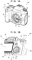
- FIGs. 1A and 1B illustrate external views of a digital camera 100 as an example of a display apparatus in which the present embodiment is applicable.
- FIG. 1A is a front perspective view of the digital camera 100
- FIG. 1B is a rear perspective view of the digital camera 100.
- a display unit 115 is provided on the back of the apparatus and displays captured images and various information.
- a display unit 126 provided outside of a viewfinder and on an upper surface of the digital camera displays various setting values of the camera, which includes shutter speed and aperture, or a timecode, which will be described later.
- the display unit 115 has a high resolution because it is also used by a user to confirm captured images.
- the display unit 126 displays information held in the apparatus, such as parameters and a timecode pertaining to image capturing, by displaying symbols, such as characters and signs, as a black-and-white binary image, and its resolution is also much lower than that of the display unit 115.
- a shutter button 61 is an operation unit for performing an image capturing instruction.
- a mode changeover switch 60 is an operation unit for switching among various modes.
- a terminal cover 40 is a cover for protecting connectors (not illustrated), such as that of a cable for connecting an external device and the digital camera 100.
- a main electronic dial 71 is a rotational operation member included in an operation unit 107, and setting values, such as shutter speed and aperture, can be changed by rotating the main electronic dial 71.
- a power supply switch 72 is an operation member for switching a power supply of the digital camera 100 on and off.
- a sub-electronic dial 73 is a rotational operation member included in the operation unit 107 and is used for moving a selection frame, scrolling through images, and the like. Further, on an inner side of the sub-electronic dial 73 is provided a four-way directional key 74 as a part of the operation unit 107.
- the four-way directional key 74 is structured to be capable of being pressed down in upper, lower, left, and right portions, respectively, and processing corresponding to a portion pressed by the user is performed. For example, an operation for selecting a menu item is performed by the user operating the four-way directional key 74.
- a set button 75 is included in the operation unit 107 and is a push button that is mainly used for determining a selection item and the like.
- An LV button 76 is a part of the operation unit 107 and is a button for switching the live view (hereinafter, LV) on and off in a menu button. In a moving image capturing mode, the LV button 76 is used for instructing to start and stop capturing (recording) of a moving image.
- An enlargement button 77 forms a part of the operation unit 107 and is an operation button for switching an enlargement mode on and off while the live view is being displayed in the image capturing mode and changing an enlargement ratio during the enlargement mode.
- the enlargement button 77 functions as an enlargement button for increasing a ratio for enlarging a reproduced image.
- a reduction button 78 forms a part of the operation unit 107 and is a button for decreasing the enlargement ratio of an enlarged reproduced image to reduce a displayed image.
- a reproduction button 79 forms a part of the operation unit 107 and is an operation button for switching between the image capturing mode and the reproduction mode. It is possible to transition to the reproduction mode and cause the latest image of images recorded in a first recording medium 105 or a second recording medium 106 to be displayed on a display unit 28 by pressing the reproduction button 79 during the image capturing mode.
- An assign button 95 is a button that forms a part of the operation unit 107 and to which a user can freely assign a function.
- the assign button 95 functions as a button for displaying a status screen in an initial state, and it can be assigned with another function, such as a function of changing setting contents or a status related to capturing and reproduction of a moving image or a function of starting capturing (recording) of a moving image. It is also possible to assign a function of displaying the status screen to an assign button other than the assign button 95.
- the status screen is a screen configured by a plurality of pages, which display setting contents or a state related to capturing and reproduction of a moving image, an internal state of the digital camera, and the like.
- a quick return mirror 12 is raised/lowered by an actuator (not illustrated) by being instructed by a system control unit 50.
- a communication terminal 10 is a communication terminal for the digital camera 100 to communicate with a (detachable) lens.
- An ocular viewfinder 16 is a look-through-type viewfinder for confirming focus and composition of an optical image of a subject obtained through a lens unit 101. Inside the ocular viewfinder 16 is housed a display unit for simply displaying parameters pertaining to image capturing and the like outside of a frame for displaying an optical image.
- a cover 202 is a cover for slots in which the first recording medium 105 and the second recording medium 106 are stored.
- a grip portion 90 is a holding portion, which has a shape that it easy for the user to hold with their right hand when the user holds the digital camera 100.
- FIG. 2 is a block diagram of the digital camera 100 in the first embodiment.
- the lens unit 101 forms a subject image, which has entered, on an image capturing surface of an image capturing device 102.
- the lens unit 101 is configured by a fixed lens group, zoom lens group, diaphragm, and correction lens group for collecting light, and the correction lens group serves a function of correcting an image forming position moved by a movement of the zoom lens group and a function of adjusting focus.
- the image capturing device 102 is, for example, a complementary metal oxide semiconductor (CMOS) image sensor or the like and converts incident light intensity into a charge amount to generate an image signal.
- CMOS complementary metal oxide semiconductor
- the image capturing device 102 outputs an image signal of a 4K image (4096 pixels horizontally ⁇ 2160 pixels vertically) at 60 frames per second.
- a camera signal processing unit 103 performs predetermined processing on an image signal from the image capturing device 102 and outputs processed image data.
- An encode processing unit 112 generates encoded data by encoding each frame of a moving image (4K moving image) obtained by the camera signal processing unit 103 using inter-frame predictive coding or the like in compression units of Group of Pictures (GOP).
- a type of encoding method is not particularly limited; however, it is assumed that encoding is performed in accordance with H.264, for example.
- a recording unit 104 records encoded moving image data generated by the encode processing unit 112 as a moving image file on the first recording medium 105 or the second recording medium 106. Both the first recording medium 105 and the second recording medium 106 may be the same type of memory cards or different types of memory cards.
- the recording unit 104 also manages moving image files recorded on the first recording medium 105 and the second recording medium 106 according to a predetermined file system.
- the operation unit 107 functions as a means for the user to input various instructions to the digital camera 100.
- the operation unit 107 then supplies input of instructions from the user to a microcomputer 108.
- the operation unit 107 includes a start/stop button for instructing recording of a moving image, a menu button for instructing a change of settings, and a display switching button for instructing a change of a display content of the display units 115 and 126, and the like.
- the microcomputer 108 functions as a main microcomputer for controlling the entire digital camera 100.
- a ROM 109 is a non-volatile memory, such as a flash ROM, and stores programs to be executed by the microcomputer 108, various parameters, and the like.
- a RAM 110 is a volatile memory used as a work area by the microcomputer 108.
- a DRAM 111 is a volatile memory that is used for temporarily storing image data that is to be processed and has been processed by the camera signal processing unit 103, the encode processing unit 112, and the recording unit 104.
- the camera signal processing unit 103 stores developed image data in the DRAM 111.
- the encode processing unit 112 reads a series of image data stored in the DRAM 111, compresses these, and writes encoded image data back in the DRAM 111.
- the recording unit 104 sequentially reads out encoded video data in the DRAM 111 and records it on the first recording medium 105 or the second recording medium 106.
- An output unit 113 performs output to an external display apparatus in a predetermined digital format, such as an HDMI ® signal or SDI signal for video signals.
- a display control unit 114 is a means for controlling a display of an image by the display unit 115 and, in accordance with an instruction from the microcomputer 108, displays video data on the display unit 115 after superimposing it with various setting menus, a title, a timecode generated by a timecode generating unit 117.
- the display unit 115 includes, for example, a liquid crystal panel and displays an image under the control of the display control unit 114. It is assumed that the display control unit 114 in the embodiment updates the display unit 115 at 60 Hz. This is for realizing a live view display at a frame rate of a moving image.
- the display control unit 114 can also display an image on the display unit 115 after superimposing it with various messages or the like.
- a bus 116 is used for transmitting data and control signals between the aforementioned elements of the digital camera 100.
- a power supply control unit 118 is configured by a battery detection circuit, a DC-DC converter, a switching circuit for switching among blocks to be powered, and the like and detects whether or not a battery 119 is mounted, a type of the battery 119, and a remaining battery amount of the battery 119.
- the power supply control unit 118 also controls the DC-DC converter based on a detection result and an instruction of the microcomputer 108 and supplies a necessary voltage for a necessary period to the respective units including the display unit 126.
- the battery 119 is a primary battery, such as an alkaline battery or a lithium battery, or a secondary battery (rechargeable battery), such as an NiCd battery, an NiMH battery, or an Li battery.
- the power supply control unit 118 is also includes a terminal for connecting an AC adapter 150 (external power supply apparatus) other than the battery 119. If the AC adapter 150 is connected, the power supply control unit 118 can charge the battery 119 with power from the AC adapter as well as supply that power to each circuit of the digital camera 100 so as to enable the digital camera 100 to operate. Therefore, the power supply control unit 118 can determine whether an AC adapter is connected from a voltage of the terminal for connecting an AC adapter and can notify the determination result to the microcomputer 108. A configuration may also be taken so as to provide a sensor for detecting a connection/disconnection of an AC adapter to/from the terminal.
- a microcomputer 121 functions as a sub-microcomputer in the digital camera 100.
- Main processing of the microcomputer 121 in the present embodiment is control of the display unit 126 via a bus 127.
- the microcomputer 108 and the microcomputer 121 are connected by a serial bus and can transmit and receive data to and from each other via the serial bus.
- a ROM 122 is a ROM, such as a flash ROM, and stores programs to be executed by the microcomputer 121 and the like.
- a RAM 123 is a volatile memory used as a work area by the microcomputer 121.
- a display control unit 125 displays various setting menus and a timecode generated by a timecode generating unit 124 on the display unit 126 according to an instruction from the microcomputer 121.
- This timecode counted by the timecode generating unit 124 can be changed by a setting from the microcomputer 121.
- the microcomputer 121 communicates with the microcomputer 108 at predetermined intervals to obtain a timecode that is counted by the timecode generating unit 117 on the microcomputer 108 side.
- the microcomputer 121 sets the obtained timecode in the timecode generating unit 124. As a result, synchronization between the timecode generating unit 117 and the timecode generating unit 124 is achieved at the above predetermined intervals.
- the digital camera 100 of the embodiment is configured by two independent buses, which are the bus 116 to which the microcomputer 108 is connected and the bus 127 to which the microcomputer 121 is connected.
- the camera signal processing unit 103, the display control unit 114, the encode processing unit 112, the recording unit 104, and the like, which are directly connected to the bus 116, which is directly connected to the microcomputer 108, need to process image data obtained from the image capturing device 102 within a preset time. Therefore, an operation clock of the processing units on the bus 116 is sufficiently high and a transmission bandwidth of the bus 116 is sufficiently wide. Meanwhile, the number of processing units directly connected to the bus 127, which is directly connected to the microcomputer 121, is less than that of the bus 116.
- the transmission bandwidth of the bus 127 is much narrower than that of the bus 116. Therefore, a clock for the operation of the processing units connected to the bus 127 including the microcomputer 121 and a data transfer clock of the bus 127 is much lower than the clocks in the microcomputer 108 and the bus 116. As a result, the power consumed in the microcomputer 121 and the processing units connected to the bus 127 can be made sufficiently smaller than the power consumed in the microcomputer 108 and the processing units connected to the bus 116.
- FIGS. 3A to 3C illustrate examples of screens to be displayed on the display unit 126 in the present embodiment.
- FIG. 3A is a screen for displaying a timecode. On this screen is displayed a timecode, which is "hour:minute:second.frame", generated by the timecode generating unit 124. It is assumed that a moving image to be captured/recorded in the present embodiment is 60 frames/second (60 fps). The intervals for updating the display unit 126 by the display control unit 125 in the embodiment are 1/15 second (15 Hz). Therefore, the "frame", which is in the least significant digit position of the timecode displayed on the display unit 126, is not incremented by 1 and is displayed as 0, 4, 8, and so on in increments of 4 frames.
- FIG. 3B is an example of a screen other than the screen for the timecode, which is displayed on the display unit 126.
- WB an F value, an ISO value, and the like are displayed.
- the display control unit 125 updates the display content of the display unit 126 only when a value of the displayed information is changed by the user's operation.
- a configuration may be taken such that the screen to be displayed on the display unit 126 is switched between FIGS. 3A and 3B each time the user performs an on/off operation of a predetermined button of the operation unit 107.
- FIG. 3C is an example of a screen to be displayed on the display unit 126 when the power of the digital camera 100 is off. It displays a state that has been set before the digital camera 100 is powered off. Therefore, the screen is not updated while the power is off. Further, by a configuration being taken so as to supply power to the display control unit 125 and the display unit 126, it is made possible to display as illustrated even when the power is turned off.
- the screen on the display unit 126 is switched by the user pressing a display panel screen display switching button (not illustrated) provided on the operation unit 107. Each time this button is pressed, the microcomputer 108 notifies the microcomputer 121 that there has been a press of the above button. Each time the microcomputer 121 receives a notification from the microcomputer 108, the microcomputer 121 controls the display control unit 125 to switch alternatingly between the screens of FIGS. 3A and 3B as the screen display on the display unit 126. However, when the microcomputer 121 receives from the microcomputer 108 a notification that there has been a power-off operation, the microcomputer 121 sets the latest setting information in the display control unit 125. Consequently, the display unit 126 display the screen illustrated in FIG. 3C .
- the microcomputer 121 returns a response for the power-off notification to the microcomputer 108.
- the microcomputer 108 sets in the power supply control unit 118 an instruction for turning the power of the digital camera off and transitions to a power off state.
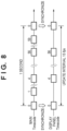
- FIG. 8 is a diagram illustrating a timing for synchronizing timecodes in the embodiment.
- a “main timecode” in the figure is a timecode generated by the timecode generating unit 117, is a high-precision timecode, and is the same as the timecode to be displayed on the display unit 115. Since the moving image frame rate of the digital camera 100 in the embodiment is set to 60 fps, the timecode generating unit 117 counts up at 1/60-second intervals. The display unit 115 also updates and displays the timecode at 1/60-second intervals.
- a "display panel timecode" of FIG. 8 is a timecode generated by the timecode generating unit 124 and is a timecode to be displayed on the display unit 126.
- the timecode generated by the timecode generating unit 124 is inferior in accuracy to the timecode generated by the timecode generating unit 117 and in the embodiment, the timecode is counted up at 1/15-second intervals (15 Hz). That is, the timecode generating unit 124 counts up the timecode as 0, 4, 8, and so on at 1/15-second intervals in increments of 4 frames, and the display unit 126 updates the screen at 15 Hz.
- the timecode generating unit 124 of the embodiment generates a timecode in synchronization with the timecode generating unit 117 at 1-second intervals, for example.
- the microcomputer 108 obtains a timecode from the timecode generating unit 117 and supplies it to the microcomputer 121 at 1-second intervals.
- the microcomputer 121 achieves synchronization by setting the timecode received from the microcomputer 108 in the timecode generating unit 124.
- the timecode generating unit 124 counts up the timecode at 1/15-second intervals based on the set timecode.
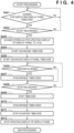
- FIG. 4 illustrates an operation flowchart in the present embodiment.
- step S401 when the user inputs from the operation unit 107 an instruction for switching the display screen of the display unit 126 to the timecode display screen, the microcomputer 108 notifies the microcomputer 121 to that effect. Upon receiving this notification, the microcomputer 121 controls the display control unit 125 so as to display the timecode screen by switching the display unit 126 from the screen of FIG. 3B to the screen of FIG. 3A .
- the recording start/stop button is a button for instructing a start of recording on a first press and a stop of recording on a second press.
- the microcomputer 108 Upon receiving from the operation unit 107 a signal indicating that there has been a press of the moving image recording start/stop button by the user, the microcomputer 108 advances the processing to step S403.
- the microcomputer 108 controls the image capturing device 102, the camera signal processing unit 103, the encode processing unit 112, and the recording unit 104 to start capturing a moving image and recording it on the recording media 105 and 106; however, since that processing is not the main focus of the present invention, a description thereof will be omitted.
- step S403 the microcomputer 108 requests that the microcomputer 121 set updating frequency of the display unit 126 to 15 Hz.
- the microcomputer 121 which has received this request, controls the display control unit 125 to sets the timecode display update frequency to 15 Hz (1/15 second).
- step S404 the microcomputer 108 instructs the timecode generating unit 117 to start advancing the timecode. Further, in step S405, the microcomputer 108 requests that the microcomputer 121 start advancing the timecode. Upon receiving this request, the microcomputer 121 instructs the timecode generating unit 124 to start advancing the timecode.
- steps S404 and S405 can be said to be the first synchronization processing of the timecode generating unit 117 and the timecode generating unit 124 when the capturing and recording of a moving image is started.
- the frame rate of a moving image is set to 60 fps, there is no particular problem if a time difference between the timecodes of the timecode generating unit 117 and the timecode generating unit 124 is 1/120, which is half of 1/60, or less.
- step S406 the microcomputer 108 determines whether or not 1 second has elapsed since it performed the previous synchronization processing.
- the previous synchronization processing also includes the processing indicated in the above steps S403 and S404.
- step S407 the microcomputer 108 advances the processing to step S408.
- step S407 the microcomputer 108 performs synchronization of the timecode generating units 117 and 124. Specifically, the microcomputer 108 obtains the timecode being counted in the timecode generating unit 117 and notifies it to the microcomputer 121. The microcomputer 121, which has received this notification, then sets the notified timecode in the timecode generating unit 124. As a result, the timecode generating units 117 and 124 count up again from the same timecode.
- step S408 the microcomputer 108 determines whether there has been input of an instruction for stopping capturing and recording of a moving image by the user (whether there has been another press of the recording start/stop button during the recording of a moving image).
- step S408 if the microcomputer 108 determines that there has been no instruction for stopping recording, the microcomputer 108 returns the processing to step S406 to continue capturing and recording the moving image.
- the timecode generated by the timecode generating unit 117 is displayed on the display unit 115 and the timecode generated by the timecode generating unit 124 is displayed on the display unit 126 (that is, in either case, if the button for displaying a timecode has been operated).
- the timecode generating units 117 and 124 will be synchronized at 1-second intervals while a moving image is being captured and recorded.
- step S408 if the microcomputer 108 determines that there has been an instruction for stopping recording, the microcomputer 108 advances the processing to step S409.
- step S409 the microcomputer 108 causes the timecode generating unit 117 to stop counting (advancing) the timecode.
- the microcomputer 108 also stops the capturing of the moving image and the recording of the moving image on the recording medium.
- step S410 the microcomputer 108 performs synchronization of the timecode generating units 117 and 124.
- the timecode generating unit 117 is counting an accurate timecode, but since the value of the frame, which is the least significant digit position of the timecode counted by the timecode generating unit 124, is a skipping value, such as 0, 4, 8, and so on, the two may not coincide with each other.
- the timecode held by the timecode generating unit 124 can be made to coincide with the timecode held by the timecode generating unit 117.
- step S411 the microcomputer 108 requests that the microcomputer 121 stop counting the timecode. Upon receiving this request, the microcomputer 121 stops the counting of the timecode generating unit 124.
- step S412 the microcomputer 108 stops the display update of the display unit 115 and requests that the microcomputer 121 also stop updating the display. Upon receiving this request, the microcomputer 121 controls the display control unit 125 to stop updating the display unit 126.
- the present embodiment it is possible to shorten the intervals for updating the timecode in the system on the microcomputer 121 side while synchronizing it with the timecode in the system on the microcomputer 108 side for which high processing is desired, at 1-second intervals. Therefore, the user can confirm a highly accurate timecode at the start and end of recording from both the display units 115 and 126.
- a loop from step S403 to step S408 may be executed.
- the processing exits the loop and transitions to step S409.
- a configuration may be taken such that when a rec run for advancing the timecode only during recording of a moving image is set, the processing in steps S401 to S412 is performed.
- the timecode generated by the timecode generating unit 117 is displayed on the display unit 115 at a 60-Hz frequency; however, when a processing unit, such as the camera signal processing unit 103 or the encode processing unit 112, is under a high load, the timecode update frequency may be temporarily set to 30 Hz or the like. As a result, the per-unit-time usage rate of the bus 116 between the display control unit 114 and the timecode generating unit 117 is reduced, and a processing unit whose processing load is high can increase its usage rate (bandwidth) of the bus 116.
- the operation unit may be provided with buttons or switches for selecting to display/hide a timecode and, if display, whether to display on both or only one of the display units 115 and 126.
- a configuration may be taken so as to, when there is input of an instruction for displaying a timecode on the display unit 126 when capturing a moving image (when YES in step S401 of FIG. 4 ), stop the display of the display unit 115 and display the timecode of the display unit 126.
- processing for display such as live view, becomes unnecessary for the display unit 115, which makes it possible to further reduce power consumption pertaining to the display.
- the configuration of the digital camera 100 in the second embodiment is the same as that of the above first embodiment ( FIGS. 1 and 2 ).
- FIGS. 5A and 5B are operation flowcharts in the second embodiment.
- the same reference numbers are given to the processes that are the same as that in FIG. 4 , and so a detailed description thereof will be omitted.
- the battery 119 and the AC adapter 150 can be connected to the digital camera 100 in the embodiment.
- step S501 the microcomputer 108 determines whether or not the operation is being performed with power from the battery 119 based on information from the power supply control unit 118. If the microcomputer 108 determines that the operation is being performed with power from the battery 119, the microcomputer 108 advances the processing to step S502. In step S502, the microcomputer 108 requests the microcomputer 121 to hide the frame, which is the least significant digit position before the second of the timecode. In response to receiving this request, the microcomputer 121 controls the display control unit 125 to hide the least significant digit position of the timecode and display the timecode up to the second on the display unit 126.
- FIG. 6A illustrates an example of a display of a timecode that includes the frame, which is the least significant digit position
- FIG. 6B illustrates an example of a display of a timecode in which the frame, which is the least significant digit position, is hidden.
- the display unit 126 displays the timecode illustrated in FIG. 6B .
- the microcomputer 108 requests the microcomputer 121 to set the frequency for updating the display unit 126 to 1 Hz (every 1 second).
- the microcomputer 121 causes the display control unit 125 to set the frequency for updating the screen of the display unit 126 to 1 Hz.
- the microcomputer 121 may set the frequency for advancing the timecode to 1 Hz and the advancement units to 60 frames in the timecode generating unit 124.
- step S501 if the microcomputer 108 determines that the operation is being performed with power from the AC adapter 150 (the battery 119 is being charged) based on information from the power supply control unit 125, the microcomputer 108 advances the processing to step S403.
- the frequency for updating the timecode of the display unit 126 is 1 Hz, which makes it possible to further reduce the power consumption in comparison to the first embodiment.
- the frequency for updating the display of the display unit 126 is set to 1 Hz; however, it may be set to another value (such as 2 Hz) that is lower than a 15-Hz frequency.
- step S408 when the microcomputer 108 determines that there has been input of an instruction for stopping capturing and recording of a moving image by the user, the microcomputer 108 advances the processing to step S409.
- step S409 the microcomputer 108 causes the timecode generating unit 117 to stop counting the timecode.
- the microcomputer 108 also stops capturing the moving image and recording it on the recording medium.
- step S410 the microcomputer 108 performs synchronization of the timecode generating units 117 and 124.
- step S411 the microcomputer 108 requests the microcomputer 121 to stop counting the timecode. Upon receiving this request, the microcomputer 121 stops the counting of the timecode generating unit 124.
- step S504 the microcomputer 108 determines whether or not the frame, which is the least significant digit position of the timecode displayed on the display unit 126, is a hidden state. If it is in a hidden state, the microcomputer 108 advances the processing to step S505.
- step S505 the microcomputer 108 requests the microcomputer 121 to display the frame, which is the least significant digit position of the timecode. Upon receiving this request, the microcomputer 121 causes the display control unit 125 to display the timecode held by the synchronized timecode generating unit 124 together with the least significant digit position. Consequently, the display of the display unit 126 switches from the state of FIG. 6B to the display illustrated in FIG. 6A .
- the intervals at which the display of the display unit 126 is updated are made longer (15 Hz ⁇ 1 Hz) than when running on the power from the AC adapter 150 (external power supply apparatus), which makes it possible to display a timecode for which power consumption has been further reduced.
- the timecode generating unit 117 and the timecode generating unit 124 are synchronized, and all the digit positions of the synchronized timecode can be displayed on the display unit 126.
- a configuration may be taken so as to, irrespective of being driven with the battery or not, display up to the second while recording a moving image (while the timecode is advancing).
- a configuration may be taken so as to hide the frame of the timecode (display it up to the second) in response to the recording of a moving image being started (Yes in step S402), synchronize the timecode (step S410), and display up to the frame (step S505) in response to the recording of the moving image being stopped (Yes in step S408).
- FIGS. 7A and 7B are operation flowcharts in the third embodiment.
- the same reference numbers are given to the processes that are the same as that in FIGS. 4 and 5A and 5B , and so a detailed description thereof will be omitted.
- the microcomputer 108 When the capturing and recording of a moving image is started, the microcomputer 108 notifies the microcomputer 121 of the start of the recording. Upon receiving this, the microcomputer 121 controls the display control unit 125 to change the frequency for updating the screen to be displayed on the display unit 126 to 15 Hz. Then, in steps S404 and S405, the timecode generating unit 117 and the timecode generating unit 124 respectively start advancing the timecodes.
- step S701 the microcomputer 108 determines if the digital camera 100 is running on the battery 119 (the AC adapter 150 is not connected) and if the remaining power of the battery 119 is less than a threshold. If the microcomputer 108 determines that this condition is satisfied, the microcomputer 108 advances the processing to step S702. Further, if the microcomputer 108 determines that this condition is not satisfied, that is, if the digital camera is running on power from the AC adapter 150 or is running on the battery 119 and the remaining amount of the battery 119 is equal to or greater than the threshold, the microcomputer 108 advances the processing to step S406.
- step S702 the microcomputer 108 requests the microcomputer 121 set the frequency for the screen of the display unit 126 to 1 Hz so as to reduce power consumption. Upon receiving this request, the microcomputer 121 controls the display control unit 125 to set the frequency for updating the timecode to 1 Hz. Further, the microcomputer 121 sets the frequency for advancing the timecode to 1 Hz and that the timecode be advanced in 60-frame units in the timecode generating unit 124.
- step S703 the microcomputer 108 requests the microcomputer 121 so as to hide the frame, which is the least significant digit position of the timecode to be displayed on the display unit 126.
- the microcomputer 121 controls the display control unit 125 to set the frame, which is the least significant digit position of the timecode, to a hidden state.
- the display screen of the display unit 126 enters the state of FIG. 6B .
- the screen update of the display unit 126 switches from 15 Hz to 1 Hz, and the frame, which is the least significant digit position of the timecode, becomes hidden. As a result, battery consumption becomes even lower, and the power can be preferentially utilized for recording the moving image.
- Embodiment(s) of the present invention can also be realized by a computer of a system or apparatus that reads out and executes computer executable instructions (e.g., one or more programs) recorded on a storage medium (which may also be referred to more fully as a 'non-transitory computer-readable storage medium') to perform the functions of one or more of the above-described embodiment(s) and/or that includes one or more circuits (e.g., application specific integrated circuit (ASIC)) for performing the functions of one or more of the above-described embodiment(s), and by a method performed by the computer of the system or apparatus by, for example, reading out and executing the computer executable instructions from the storage medium to perform the functions of one or more of the above-described embodiment(s) and/or controlling the one or more circuits to perform the functions of one or more of the above-described embodiment(s).
- computer executable instructions e.g., one or more programs
- a storage medium which may also be referred to more fully as
- the computer may comprise one or more processors (e.g., central processing unit (CPU), micro processing unit (MPU)) and may include a network of separate computers or separate processors to read out and execute the computer executable instructions.
- the computer executable instructions may be provided to the computer, for example, from a network or the storage medium.
- the storage medium may include, for example, one or more of a hard disk, a random-access memory (RAM), a read only memory (ROM), a storage of distributed computing systems, an optical disk (such as a compact disc (CD), digital versatile disc (DVD), or Blu-ray Disc (BD) TM ), a flash memory device, a memory card, and the like.
- This invention provides an image capturing apparatus including a first display unit capable of displaying a captured image and a second display unit configured to display information related to image capturing, where the apparatus comprises a generating unit configured to generate a timecode corresponding to a frame rate at which an image capturing unit performs image capturing; a first display control unit configured to control so as to display the timecode generated in the generating unit on the first display unit at first intervals; and a second display control unit configured to control so as to display the timecode generated in the generating unit on the second display unit at second intervals that are longer than the first intervals.
Landscapes
- Engineering & Computer Science (AREA)
- Multimedia (AREA)
- Signal Processing (AREA)
- Physics & Mathematics (AREA)
- General Physics & Mathematics (AREA)
- Human Computer Interaction (AREA)
- Studio Devices (AREA)
- Indication In Cameras, And Counting Of Exposures (AREA)
- Controls And Circuits For Display Device (AREA)
- Camera Bodies And Camera Details Or Accessories (AREA)
Abstract
Description
- The present invention relates to an image capturing apparatus and a control method and a computer program.
- Image capturing apparatuses typified by digital cameras are provided with a display panel capable of displaying a state of the camera, such as camera setting information including shutter speed, white balance setting, and auto focus setting, the number of still images and a duration of video that can be recorded in a recording medium, and warning information. There also are apparatuses that display the above information on a display screen even when power is off.
- Since display panels, such as LCD panels, provided in digital cameras usually display images obtained by an image capturing sensor in live view, they are often driven at 60 Hz or 30 Hz. However, it is necessary to suppress power consumption in order to display information on a display panel while power is off. Therefore, it is necessary to keep intervals for updating a display of the display panel short.
-
Patent Document 1,Japanese Patent Laid-Open No. 2003-244529 - However, the
above Patent Document 1 reduces a frame rate of a display apparatus to reduce a processing load of a camera when the processing load is large and does not suppress power consumption when the processing load of the camera is not large. - The present invention provides a technique for displaying a timecode while suppressing power consumption.
- The present invention in its first aspect provides an image capturing apparatus as specified in
claims 1 to 16. - The present invention in its second aspect provides a method of controlling an image capturing apparatus as specified in claim 17.
- The present invention in its third aspect provides a computer program as specified in claim 18.
- According to the present invention, it is possible to display a timecode while suppressing power consumption.
- Further features of the present invention will become apparent from the following description of exemplary embodiments (with reference to the attached drawings).
-
-
FIGs. 1A and 1B are external views of an image capturing apparatus in the present embodiment. -
FIG. 2 is a block diagram of a schematic configuration of the image capturing apparatus in the present embodiment. -
FIGs. 3A to 3C are diagrams illustrating examples of displays of display screens to be displayed on a display panel in a first embodiment. -
FIG. 4 is an operation flowchart of the first embodiment. -
FIGS. 5A and5B are operation flowcharts of a second embodiment. -
FIGS. 6A and 6B are diagrams illustrating examples of displays of display screens to be displayed on a display panel in the second embodiment. -
FIGS. 7A and7B are operation flowcharts of the third embodiment. -
FIG. 8 is a diagram illustrating timecode synchronization in the first embodiment. - Hereinafter, embodiments will be described in detail with reference to the attached drawings. Note, the following embodiments are not intended to limit the scope of the claimed invention. Multiple features are described in the embodiments, but limitation is not made an invention that require all such features, and multiple such features may be combined as appropriate. Furthermore, in the attached drawings, the same reference numerals are given to the same or similar configurations, and redundant description thereof is omitted.
-
FIGs. 1A and 1B illustrate external views of adigital camera 100 as an example of a display apparatus in which the present embodiment is applicable.FIG. 1A is a front perspective view of thedigital camera 100, andFIG. 1B is a rear perspective view of thedigital camera 100. Adisplay unit 115 is provided on the back of the apparatus and displays captured images and various information. Adisplay unit 126 provided outside of a viewfinder and on an upper surface of the digital camera displays various setting values of the camera, which includes shutter speed and aperture, or a timecode, which will be described later. Thedisplay unit 115 has a high resolution because it is also used by a user to confirm captured images. In contrast, thedisplay unit 126 displays information held in the apparatus, such as parameters and a timecode pertaining to image capturing, by displaying symbols, such as characters and signs, as a black-and-white binary image, and its resolution is also much lower than that of thedisplay unit 115. Ashutter button 61 is an operation unit for performing an image capturing instruction. Amode changeover switch 60 is an operation unit for switching among various modes. Aterminal cover 40 is a cover for protecting connectors (not illustrated), such as that of a cable for connecting an external device and thedigital camera 100. A mainelectronic dial 71 is a rotational operation member included in anoperation unit 107, and setting values, such as shutter speed and aperture, can be changed by rotating the mainelectronic dial 71. Apower supply switch 72 is an operation member for switching a power supply of thedigital camera 100 on and off. Asub-electronic dial 73 is a rotational operation member included in theoperation unit 107 and is used for moving a selection frame, scrolling through images, and the like. Further, on an inner side of thesub-electronic dial 73 is provided a four-waydirectional key 74 as a part of theoperation unit 107. The four-waydirectional key 74 is structured to be capable of being pressed down in upper, lower, left, and right portions, respectively, and processing corresponding to a portion pressed by the user is performed. For example, an operation for selecting a menu item is performed by the user operating the four-waydirectional key 74. Aset button 75 is included in theoperation unit 107 and is a push button that is mainly used for determining a selection item and the like. AnLV button 76 is a part of theoperation unit 107 and is a button for switching the live view (hereinafter, LV) on and off in a menu button. In a moving image capturing mode, theLV button 76 is used for instructing to start and stop capturing (recording) of a moving image. Anenlargement button 77 forms a part of theoperation unit 107 and is an operation button for switching an enlargement mode on and off while the live view is being displayed in the image capturing mode and changing an enlargement ratio during the enlargement mode. In a reproduction mode, theenlargement button 77 functions as an enlargement button for increasing a ratio for enlarging a reproduced image. Areduction button 78 forms a part of theoperation unit 107 and is a button for decreasing the enlargement ratio of an enlarged reproduced image to reduce a displayed image. Areproduction button 79 forms a part of theoperation unit 107 and is an operation button for switching between the image capturing mode and the reproduction mode. It is possible to transition to the reproduction mode and cause the latest image of images recorded in afirst recording medium 105 or asecond recording medium 106 to be displayed on a display unit 28 by pressing thereproduction button 79 during the image capturing mode. Anassign button 95 is a button that forms a part of theoperation unit 107 and to which a user can freely assign a function. Theassign button 95 functions as a button for displaying a status screen in an initial state, and it can be assigned with another function, such as a function of changing setting contents or a status related to capturing and reproduction of a moving image or a function of starting capturing (recording) of a moving image. It is also possible to assign a function of displaying the status screen to an assign button other than theassign button 95. The status screen is a screen configured by a plurality of pages, which display setting contents or a state related to capturing and reproduction of a moving image, an internal state of the digital camera, and the like. - A
quick return mirror 12 is raised/lowered by an actuator (not illustrated) by being instructed by a system control unit 50. Acommunication terminal 10 is a communication terminal for thedigital camera 100 to communicate with a (detachable) lens. Anocular viewfinder 16 is a look-through-type viewfinder for confirming focus and composition of an optical image of a subject obtained through alens unit 101. Inside theocular viewfinder 16 is housed a display unit for simply displaying parameters pertaining to image capturing and the like outside of a frame for displaying an optical image. - A
cover 202 is a cover for slots in which thefirst recording medium 105 and thesecond recording medium 106 are stored. Agrip portion 90 is a holding portion, which has a shape that it easy for the user to hold with their right hand when the user holds thedigital camera 100. - This concludes a description pertaining to a structure of a digital camera serving as a display apparatus in which embodiments are to be applied. Hereinafter, a description will be given for first to third embodiments based on the above structure.
-
FIG. 2 is a block diagram of thedigital camera 100 in the first embodiment. - The
lens unit 101 forms a subject image, which has entered, on an image capturing surface of animage capturing device 102. Thelens unit 101 is configured by a fixed lens group, zoom lens group, diaphragm, and correction lens group for collecting light, and the correction lens group serves a function of correcting an image forming position moved by a movement of the zoom lens group and a function of adjusting focus. - The
image capturing device 102 is, for example, a complementary metal oxide semiconductor (CMOS) image sensor or the like and converts incident light intensity into a charge amount to generate an image signal. Theimage capturing device 102 outputs an image signal of a 4K image (4096 pixels horizontally × 2160 pixels vertically) at 60 frames per second. - A camera
signal processing unit 103 performs predetermined processing on an image signal from theimage capturing device 102 and outputs processed image data. - An encode
processing unit 112 generates encoded data by encoding each frame of a moving image (4K moving image) obtained by the camerasignal processing unit 103 using inter-frame predictive coding or the like in compression units of Group of Pictures (GOP). A type of encoding method is not particularly limited; however, it is assumed that encoding is performed in accordance with H.264, for example. - A
recording unit 104 records encoded moving image data generated by the encodeprocessing unit 112 as a moving image file on thefirst recording medium 105 or thesecond recording medium 106. Both thefirst recording medium 105 and thesecond recording medium 106 may be the same type of memory cards or different types of memory cards. Therecording unit 104 also manages moving image files recorded on thefirst recording medium 105 and thesecond recording medium 106 according to a predetermined file system. - The
operation unit 107 functions as a means for the user to input various instructions to thedigital camera 100. Theoperation unit 107 then supplies input of instructions from the user to amicrocomputer 108. As already described, theoperation unit 107 includes a start/stop button for instructing recording of a moving image, a menu button for instructing a change of settings, and a display switching button for instructing a change of a display content of thedisplay units - The
microcomputer 108 functions as a main microcomputer for controlling the entiredigital camera 100. AROM 109 is a non-volatile memory, such as a flash ROM, and stores programs to be executed by themicrocomputer 108, various parameters, and the like. ARAM 110 is a volatile memory used as a work area by themicrocomputer 108. - A
DRAM 111 is a volatile memory that is used for temporarily storing image data that is to be processed and has been processed by the camerasignal processing unit 103, the encodeprocessing unit 112, and therecording unit 104. Specifically, the camerasignal processing unit 103 stores developed image data in theDRAM 111. The encodeprocessing unit 112 reads a series of image data stored in theDRAM 111, compresses these, and writes encoded image data back in theDRAM 111. Therecording unit 104 sequentially reads out encoded video data in theDRAM 111 and records it on thefirst recording medium 105 or thesecond recording medium 106. - An
output unit 113 performs output to an external display apparatus in a predetermined digital format, such as an HDMI® signal or SDI signal for video signals. Adisplay control unit 114 is a means for controlling a display of an image by thedisplay unit 115 and, in accordance with an instruction from themicrocomputer 108, displays video data on thedisplay unit 115 after superimposing it with various setting menus, a title, a timecode generated by atimecode generating unit 117. Thedisplay unit 115 includes, for example, a liquid crystal panel and displays an image under the control of thedisplay control unit 114. It is assumed that thedisplay control unit 114 in the embodiment updates thedisplay unit 115 at 60 Hz. This is for realizing a live view display at a frame rate of a moving image. Thedisplay control unit 114 can also display an image on thedisplay unit 115 after superimposing it with various messages or the like. Abus 116 is used for transmitting data and control signals between the aforementioned elements of thedigital camera 100. - A power
supply control unit 118 is configured by a battery detection circuit, a DC-DC converter, a switching circuit for switching among blocks to be powered, and the like and detects whether or not abattery 119 is mounted, a type of thebattery 119, and a remaining battery amount of thebattery 119. The powersupply control unit 118 also controls the DC-DC converter based on a detection result and an instruction of themicrocomputer 108 and supplies a necessary voltage for a necessary period to the respective units including thedisplay unit 126. Thebattery 119 is a primary battery, such as an alkaline battery or a lithium battery, or a secondary battery (rechargeable battery), such as an NiCd battery, an NiMH battery, or an Li battery. - The power
supply control unit 118 is also includes a terminal for connecting an AC adapter 150 (external power supply apparatus) other than thebattery 119. If theAC adapter 150 is connected, the powersupply control unit 118 can charge thebattery 119 with power from the AC adapter as well as supply that power to each circuit of thedigital camera 100 so as to enable thedigital camera 100 to operate. Therefore, the powersupply control unit 118 can determine whether an AC adapter is connected from a voltage of the terminal for connecting an AC adapter and can notify the determination result to themicrocomputer 108. A configuration may also be taken so as to provide a sensor for detecting a connection/disconnection of an AC adapter to/from the terminal. - A
microcomputer 121 functions as a sub-microcomputer in thedigital camera 100. Main processing of themicrocomputer 121 in the present embodiment is control of thedisplay unit 126 via abus 127. Themicrocomputer 108 and themicrocomputer 121 are connected by a serial bus and can transmit and receive data to and from each other via the serial bus. AROM 122 is a ROM, such as a flash ROM, and stores programs to be executed by themicrocomputer 121 and the like. ARAM 123 is a volatile memory used as a work area by themicrocomputer 121. - A
display control unit 125 displays various setting menus and a timecode generated by atimecode generating unit 124 on thedisplay unit 126 according to an instruction from themicrocomputer 121. - This timecode counted by the
timecode generating unit 124 can be changed by a setting from themicrocomputer 121. Although details will be described later, themicrocomputer 121 communicates with themicrocomputer 108 at predetermined intervals to obtain a timecode that is counted by thetimecode generating unit 117 on themicrocomputer 108 side. Themicrocomputer 121 then sets the obtained timecode in thetimecode generating unit 124. As a result, synchronization between thetimecode generating unit 117 and thetimecode generating unit 124 is achieved at the above predetermined intervals. - As illustrated in
FIG. 2 , thedigital camera 100 of the embodiment is configured by two independent buses, which are thebus 116 to which themicrocomputer 108 is connected and thebus 127 to which themicrocomputer 121 is connected. The camerasignal processing unit 103, thedisplay control unit 114, the encodeprocessing unit 112, therecording unit 104, and the like, which are directly connected to thebus 116, which is directly connected to themicrocomputer 108, need to process image data obtained from theimage capturing device 102 within a preset time. Therefore, an operation clock of the processing units on thebus 116 is sufficiently high and a transmission bandwidth of thebus 116 is sufficiently wide. Meanwhile, the number of processing units directly connected to thebus 127, which is directly connected to themicrocomputer 121, is less than that of thebus 116. Since the main processing of themicrocomputer 121 is control of a display of thedisplay unit 126 via thebus 127, the transmission bandwidth of thebus 127 is much narrower than that of thebus 116. Therefore, a clock for the operation of the processing units connected to thebus 127 including themicrocomputer 121 and a data transfer clock of thebus 127 is much lower than the clocks in themicrocomputer 108 and thebus 116. As a result, the power consumed in themicrocomputer 121 and the processing units connected to thebus 127 can be made sufficiently smaller than the power consumed in themicrocomputer 108 and the processing units connected to thebus 116. -
FIGS. 3A to 3C illustrate examples of screens to be displayed on thedisplay unit 126 in the present embodiment.FIG. 3A is a screen for displaying a timecode. On this screen is displayed a timecode, which is "hour:minute:second.frame", generated by thetimecode generating unit 124. It is assumed that a moving image to be captured/recorded in the present embodiment is 60 frames/second (60 fps). The intervals for updating thedisplay unit 126 by thedisplay control unit 125 in the embodiment are 1/15 second (15 Hz). Therefore, the "frame", which is in the least significant digit position of the timecode displayed on thedisplay unit 126, is not incremented by 1 and is displayed as 0, 4, 8, and so on in increments of 4 frames. -
FIG. 3B is an example of a screen other than the screen for the timecode, which is displayed on thedisplay unit 126. In the figure, WB, an F value, an ISO value, and the like are displayed. UnlikeFIG. 3A , inFIG. 3B , thedisplay control unit 125 updates the display content of thedisplay unit 126 only when a value of the displayed information is changed by the user's operation. - A configuration may be taken such that the screen to be displayed on the
display unit 126 is switched betweenFIGS. 3A and 3B each time the user performs an on/off operation of a predetermined button of theoperation unit 107. -
FIG. 3C is an example of a screen to be displayed on thedisplay unit 126 when the power of thedigital camera 100 is off. It displays a state that has been set before thedigital camera 100 is powered off. Therefore, the screen is not updated while the power is off. Further, by a configuration being taken so as to supply power to thedisplay control unit 125 and thedisplay unit 126, it is made possible to display as illustrated even when the power is turned off. - The screen on the
display unit 126 is switched by the user pressing a display panel screen display switching button (not illustrated) provided on theoperation unit 107. Each time this button is pressed, themicrocomputer 108 notifies themicrocomputer 121 that there has been a press of the above button. Each time themicrocomputer 121 receives a notification from themicrocomputer 108, themicrocomputer 121 controls thedisplay control unit 125 to switch alternatingly between the screens ofFIGS. 3A and 3B as the screen display on thedisplay unit 126. However, when themicrocomputer 121 receives from the microcomputer 108 a notification that there has been a power-off operation, themicrocomputer 121 sets the latest setting information in thedisplay control unit 125. Consequently, thedisplay unit 126 display the screen illustrated inFIG. 3C . Thereafter, themicrocomputer 121 returns a response for the power-off notification to themicrocomputer 108. After receiving this response, themicrocomputer 108 sets in the powersupply control unit 118 an instruction for turning the power of the digital camera off and transitions to a power off state. -
FIG. 8 is a diagram illustrating a timing for synchronizing timecodes in the embodiment. - A "main timecode" in the figure is a timecode generated by the
timecode generating unit 117, is a high-precision timecode, and is the same as the timecode to be displayed on thedisplay unit 115. Since the moving image frame rate of thedigital camera 100 in the embodiment is set to 60 fps, thetimecode generating unit 117 counts up at 1/60-second intervals. Thedisplay unit 115 also updates and displays the timecode at 1/60-second intervals. - On the other hand, a "display panel timecode" of
FIG. 8 is a timecode generated by thetimecode generating unit 124 and is a timecode to be displayed on thedisplay unit 126. The timecode generated by thetimecode generating unit 124 is inferior in accuracy to the timecode generated by thetimecode generating unit 117 and in the embodiment, the timecode is counted up at 1/15-second intervals (15 Hz). That is, thetimecode generating unit 124 counts up the timecode as 0, 4, 8, and so on at 1/15-second intervals in increments of 4 frames, and thedisplay unit 126 updates the screen at 15 Hz. However, it is necessary to maintain the accuracy of the timecode generated by thetimecode generating unit 117. Therefore, thetimecode generating unit 124 of the embodiment generates a timecode in synchronization with thetimecode generating unit 117 at 1-second intervals, for example. Specifically, themicrocomputer 108 obtains a timecode from thetimecode generating unit 117 and supplies it to themicrocomputer 121 at 1-second intervals. Themicrocomputer 121 achieves synchronization by setting the timecode received from themicrocomputer 108 in thetimecode generating unit 124. Thetimecode generating unit 124 counts up the timecode at 1/15-second intervals based on the set timecode. -
FIG. 4 illustrates an operation flowchart in the present embodiment. - In step S401, when the user inputs from the
operation unit 107 an instruction for switching the display screen of thedisplay unit 126 to the timecode display screen, themicrocomputer 108 notifies themicrocomputer 121 to that effect. Upon receiving this notification, themicrocomputer 121 controls thedisplay control unit 125 so as to display the timecode screen by switching thedisplay unit 126 from the screen ofFIG. 3B to the screen ofFIG. 3A . - Next, the
microcomputer 108 waits for the user to press the moving image recording start/stop button of theoperation unit 107. The recording start/stop button is a button for instructing a start of recording on a first press and a stop of recording on a second press. - Upon receiving from the operation unit 107 a signal indicating that there has been a press of the moving image recording start/stop button by the user, the
microcomputer 108 advances the processing to step S403. - At this time, the
microcomputer 108 controls theimage capturing device 102, the camerasignal processing unit 103, the encodeprocessing unit 112, and therecording unit 104 to start capturing a moving image and recording it on therecording media - In step S403, the
microcomputer 108 requests that themicrocomputer 121 set updating frequency of thedisplay unit 126 to 15 Hz. Themicrocomputer 121, which has received this request, controls thedisplay control unit 125 to sets the timecode display update frequency to 15 Hz (1/15 second). - In step S404, the
microcomputer 108 instructs thetimecode generating unit 117 to start advancing the timecode. Further, in step S405, themicrocomputer 108 requests that themicrocomputer 121 start advancing the timecode. Upon receiving this request, themicrocomputer 121 instructs thetimecode generating unit 124 to start advancing the timecode. - There almost is no time lag between the above steps S403 and S404. Therefore, the processing of steps S404 and S405 can be said to be the first synchronization processing of the
timecode generating unit 117 and thetimecode generating unit 124 when the capturing and recording of a moving image is started. In the embodiment, since the frame rate of a moving image is set to 60 fps, there is no particular problem if a time difference between the timecodes of thetimecode generating unit 117 and thetimecode generating unit 124 is 1/120, which is half of 1/60, or less. - In step S406, the
microcomputer 108 determines whether or not 1 second has elapsed since it performed the previous synchronization processing. The previous synchronization processing also includes the processing indicated in the above steps S403 and S404. - When the
microcomputer 108 determines that 1 second has elapsed from the previous synchronization processing, themicrocomputer 108 advances the processing to step S407, and if not, themicrocomputer 108 advances the processing to step S408. - In step S407, the
microcomputer 108 performs synchronization of thetimecode generating units microcomputer 108 obtains the timecode being counted in thetimecode generating unit 117 and notifies it to themicrocomputer 121. Themicrocomputer 121, which has received this notification, then sets the notified timecode in thetimecode generating unit 124. As a result, thetimecode generating units - Meanwhile, in step S408, the
microcomputer 108 determines whether there has been input of an instruction for stopping capturing and recording of a moving image by the user (whether there has been another press of the recording start/stop button during the recording of a moving image). - In step S408, if the
microcomputer 108 determines that there has been no instruction for stopping recording, themicrocomputer 108 returns the processing to step S406 to continue capturing and recording the moving image. As a result, so long as a moving image is being captured and recorded, the timecode generated by thetimecode generating unit 117 is displayed on thedisplay unit 115 and the timecode generated by thetimecode generating unit 124 is displayed on the display unit 126 (that is, in either case, if the button for displaying a timecode has been operated). Thetimecode generating units - On the other hand, in step S408, if the
microcomputer 108 determines that there has been an instruction for stopping recording, themicrocomputer 108 advances the processing to step S409. - In step S409, the
microcomputer 108 causes thetimecode generating unit 117 to stop counting (advancing) the timecode. Themicrocomputer 108 also stops the capturing of the moving image and the recording of the moving image on the recording medium. - Next, in step S410, the
microcomputer 108 performs synchronization of thetimecode generating units timecode generating unit 117 is counting an accurate timecode, but since the value of the frame, which is the least significant digit position of the timecode counted by thetimecode generating unit 124, is a skipping value, such as 0, 4, 8, and so on, the two may not coincide with each other. By performing the processing of step S410, the timecode held by thetimecode generating unit 124 can be made to coincide with the timecode held by thetimecode generating unit 117. - Then, in step S411, the
microcomputer 108 requests that themicrocomputer 121 stop counting the timecode. Upon receiving this request, themicrocomputer 121 stops the counting of thetimecode generating unit 124. - Then, in step S412, the
microcomputer 108 stops the display update of thedisplay unit 115 and requests that themicrocomputer 121 also stop updating the display. Upon receiving this request, themicrocomputer 121 controls thedisplay control unit 125 to stop updating thedisplay unit 126. - As described above, according to the present embodiment, it is possible to shorten the intervals for updating the timecode in the system on the
microcomputer 121 side while synchronizing it with the timecode in the system on themicrocomputer 108 side for which high processing is desired, at 1-second intervals. Therefore, the user can confirm a highly accurate timecode at the start and end of recording from both thedisplay units - In the above, a description has been given for an example of displaying a timecode at the time of capturing and recording a moving image. However, irrespective of capturing and recording of a moving image, when the user operates the
operation unit 107 to set to a free run for advancing the timecode regardless of whether or not a moving image is being recorded, a loop from step S403 to step S408 may be executed. Then, when the user inputs a stop instruction, the processing exits the loop and transitions to step S409. On the other hand, a configuration may be taken such that when a rec run for advancing the timecode only during recording of a moving image is set, the processing in steps S401 to S412 is performed. - In the above embodiment, it is assumed that the timecode generated by the
timecode generating unit 117 is displayed on thedisplay unit 115 at a 60-Hz frequency; however, when a processing unit, such as the camerasignal processing unit 103 or the encodeprocessing unit 112, is under a high load, the timecode update frequency may be temporarily set to 30 Hz or the like. As a result, the per-unit-time usage rate of thebus 116 between thedisplay control unit 114 and thetimecode generating unit 117 is reduced, and a processing unit whose processing load is high can increase its usage rate (bandwidth) of thebus 116. - In addition, the operation unit may be provided with buttons or switches for selecting to display/hide a timecode and, if display, whether to display on both or only one of the
display units - Furthermore, a configuration may be taken so as to, when there is input of an instruction for displaying a timecode on the
display unit 126 when capturing a moving image (when YES in step S401 ofFIG. 4 ), stop the display of thedisplay unit 115 and display the timecode of thedisplay unit 126. In such a case, processing for display, such as live view, becomes unnecessary for thedisplay unit 115, which makes it possible to further reduce power consumption pertaining to the display. - Next, a second embodiment will be described. The configuration of the
digital camera 100 in the second embodiment is the same as that of the above first embodiment (FIGS. 1 and2 ). -
FIGS. 5A and5B are operation flowcharts in the second embodiment. InFIGS. 5A and5B , the same reference numbers are given to the processes that are the same as that inFIG. 4 , and so a detailed description thereof will be omitted. As previously described, thebattery 119 and theAC adapter 150 can be connected to thedigital camera 100 in the embodiment. - In step S501, the
microcomputer 108 determines whether or not the operation is being performed with power from thebattery 119 based on information from the powersupply control unit 118. If themicrocomputer 108 determines that the operation is being performed with power from thebattery 119, themicrocomputer 108 advances the processing to step S502. In step S502, themicrocomputer 108 requests themicrocomputer 121 to hide the frame, which is the least significant digit position before the second of the timecode. In response to receiving this request, themicrocomputer 121 controls thedisplay control unit 125 to hide the least significant digit position of the timecode and display the timecode up to the second on thedisplay unit 126.FIG. 6A illustrates an example of a display of a timecode that includes the frame, which is the least significant digit position, andFIG. 6B illustrates an example of a display of a timecode in which the frame, which is the least significant digit position, is hidden. As a result of the processing in step S502, thedisplay unit 126 displays the timecode illustrated inFIG. 6B . Then, in step S503, themicrocomputer 108 requests themicrocomputer 121 to set the frequency for updating thedisplay unit 126 to 1 Hz (every 1 second). Upon receiving this request, themicrocomputer 121 causes thedisplay control unit 125 to set the frequency for updating the screen of thedisplay unit 126 to 1 Hz. At this time, themicrocomputer 121 may set the frequency for advancing the timecode to 1 Hz and the advancement units to 60 frames in thetimecode generating unit 124. - In step S501, if the
microcomputer 108 determines that the operation is being performed with power from the AC adapter 150 (thebattery 119 is being charged) based on information from the powersupply control unit 125, themicrocomputer 108 advances the processing to step S403. - As a result of the above, when power is not being receiving from the
AC adapter 150, the frequency for updating the timecode of thedisplay unit 126 is 1 Hz, which makes it possible to further reduce the power consumption in comparison to the first embodiment. In the above, when being driven on thebattery 119, the frequency for updating the display of thedisplay unit 126 is set to 1 Hz; however, it may be set to another value (such as 2 Hz) that is lower than a 15-Hz frequency. - In step S408, when the
microcomputer 108 determines that there has been input of an instruction for stopping capturing and recording of a moving image by the user, themicrocomputer 108 advances the processing to step S409. - In step S409, the
microcomputer 108 causes thetimecode generating unit 117 to stop counting the timecode. Themicrocomputer 108 also stops capturing the moving image and recording it on the recording medium. In step S410, themicrocomputer 108 performs synchronization of thetimecode generating units microcomputer 108 requests themicrocomputer 121 to stop counting the timecode. Upon receiving this request, themicrocomputer 121 stops the counting of thetimecode generating unit 124. - In step S504, the
microcomputer 108 determines whether or not the frame, which is the least significant digit position of the timecode displayed on thedisplay unit 126, is a hidden state. If it is in a hidden state, themicrocomputer 108 advances the processing to step S505. In step S505, themicrocomputer 108 requests themicrocomputer 121 to display the frame, which is the least significant digit position of the timecode. Upon receiving this request, themicrocomputer 121 causes thedisplay control unit 125 to display the timecode held by the synchronizedtimecode generating unit 124 together with the least significant digit position. Consequently, the display of thedisplay unit 126 switches from the state ofFIG. 6B to the display illustrated inFIG. 6A . - As described above, according to the second embodiment, when running only on the
battery 119, the intervals at which the display of thedisplay unit 126 is updated are made longer (15 Hz → 1 Hz) than when running on the power from the AC adapter 150 (external power supply apparatus), which makes it possible to display a timecode for which power consumption has been further reduced. When the recording of a moving image is stopped, thetimecode generating unit 117 and thetimecode generating unit 124 are synchronized, and all the digit positions of the synchronized timecode can be displayed on thedisplay unit 126. - In the second embodiment, when running only on the
battery 119, the number of digit positions of the display of the timecode is reduced, displaying up to the second rather than displaying up to the frame. However, a configuration may be taken so as to, irrespective of being driven with the battery or not, display up to the second while recording a moving image (while the timecode is advancing). In such a case, a configuration may be taken so as to hide the frame of the timecode (display it up to the second) in response to the recording of a moving image being started (Yes in step S402), synchronize the timecode (step S410), and display up to the frame (step S505) in response to the recording of the moving image being stopped (Yes in step S408). - Next, a third embodiment will be described. In the third embodiment, it is also assumed that the configuration and the basic operation of the
digital camera 100 is the same as those of the first and second embodiments, and so a description thereof will be omitted. -
FIGS. 7A and7B are operation flowcharts in the third embodiment. InFIGS. 7A and7B , the same reference numbers are given to the processes that are the same as that inFIGS. 4 and5A and5B , and so a detailed description thereof will be omitted. - When the capturing and recording of a moving image is started, the
microcomputer 108 notifies themicrocomputer 121 of the start of the recording. Upon receiving this, themicrocomputer 121 controls thedisplay control unit 125 to change the frequency for updating the screen to be displayed on thedisplay unit 126 to 15 Hz. Then, in steps S404 and S405, thetimecode generating unit 117 and thetimecode generating unit 124 respectively start advancing the timecodes. - In step S701, the
microcomputer 108 determines if thedigital camera 100 is running on the battery 119 (theAC adapter 150 is not connected) and if the remaining power of thebattery 119 is less than a threshold. If themicrocomputer 108 determines that this condition is satisfied, themicrocomputer 108 advances the processing to step S702. Further, if themicrocomputer 108 determines that this condition is not satisfied, that is, if the digital camera is running on power from theAC adapter 150 or is running on thebattery 119 and the remaining amount of thebattery 119 is equal to or greater than the threshold, themicrocomputer 108 advances the processing to step S406. - In step S702, the
microcomputer 108 requests themicrocomputer 121 set the frequency for the screen of thedisplay unit 126 to 1 Hz so as to reduce power consumption. Upon receiving this request, themicrocomputer 121 controls thedisplay control unit 125 to set the frequency for updating the timecode to 1 Hz. Further, themicrocomputer 121 sets the frequency for advancing the timecode to 1 Hz and that the timecode be advanced in 60-frame units in thetimecode generating unit 124. - Next, in step S703, the
microcomputer 108 requests themicrocomputer 121 so as to hide the frame, which is the least significant digit position of the timecode to be displayed on thedisplay unit 126. Upon receiving this request, themicrocomputer 121 controls thedisplay control unit 125 to set the frame, which is the least significant digit position of the timecode, to a hidden state. As a result, the display screen of thedisplay unit 126 enters the state ofFIG. 6B . - Thereafter, the processing is the same as that of the flowcharts of
FIGS. 5A and5B , and so a description thereof will be omitted. - As described above, according to the third embodiment, when the remaining amount of the
battery 119 falls below the threshold while capturing and recording a moving image on the power of thebattery 119, the screen update of thedisplay unit 126 switches from 15 Hz to 1 Hz, and the frame, which is the least significant digit position of the timecode, becomes hidden. As a result, battery consumption becomes even lower, and the power can be preferentially utilized for recording the moving image. - Embodiment(s) of the present invention can also be realized by a computer of a system or apparatus that reads out and executes computer executable instructions (e.g., one or more programs) recorded on a storage medium (which may also be referred to more fully as a 'non-transitory computer-readable storage medium') to perform the functions of one or more of the above-described embodiment(s) and/or that includes one or more circuits (e.g., application specific integrated circuit (ASIC)) for performing the functions of one or more of the above-described embodiment(s), and by a method performed by the computer of the system or apparatus by, for example, reading out and executing the computer executable instructions from the storage medium to perform the functions of one or more of the above-described embodiment(s) and/or controlling the one or more circuits to perform the functions of one or more of the above-described embodiment(s). The computer may comprise one or more processors (e.g., central processing unit (CPU), micro processing unit (MPU)) and may include a network of separate computers or separate processors to read out and execute the computer executable instructions. The computer executable instructions may be provided to the computer, for example, from a network or the storage medium. The storage medium may include, for example, one or more of a hard disk, a random-access memory (RAM), a read only memory (ROM), a storage of distributed computing systems, an optical disk (such as a compact disc (CD), digital versatile disc (DVD), or Blu-ray Disc (BD)™), a flash memory device, a memory card, and the like.
- While the present invention has been described with reference to exemplary embodiments, it is to be understood that the invention is not limited to the disclosed exemplary embodiments. The scope of the following claims is to be accorded the broadest interpretation so as to encompass all such modifications and equivalent structures and functions.
- This invention provides an image capturing apparatus including a first display unit capable of displaying a captured image and a second display unit configured to display information related to image capturing, where the apparatus comprises a generating unit configured to generate a timecode corresponding to a frame rate at which an image capturing unit performs image capturing; a first display control unit configured to control so as to display the timecode generated in the generating unit on the first display unit at first intervals; and a second display control unit configured to control so as to display the timecode generated in the generating unit on the second display unit at second intervals that are longer than the first intervals.
Claims (18)
- An image capturing apparatus including a first display unit capable of displaying a captured image and a second display unit configured to display information related to image capturing, the apparatus characterized by comprising:a generating unit for generating a timecode corresponding to a frame rate at which an image capturing means performs image capturing;a first display control means for controlling so as to display the timecode generated in the generating means on the first display unit at first intervals; anda second display control means for controlling so as to display the timecode generated in the generating means on the second display unit at second intervals that are longer than the first intervals.
- The image capturing apparatus according to claim 1, wherein the second display unit is a display unit that displays information related to image capturing held inside the image capturing apparatus using a symbol including a character and a sign.
- The image capturing apparatus according to claim 1 or 2, wherein the first intervals are of a frequency greater than or equal to the frame rate.
- The image capturing apparatus according to claim 3, wherein the first intervals are intervals corresponding to the frame rate.
- The image capturing apparatus according to claim 1, whereinthe generating means includes a first timecode generating means and a second timecode generating means,the first display control means controls so as to display a timecode generated in the first timecode generating means on the first display unit at the first intervals, andthe second display control means controls so as to display a timecode generated in the second timecode generating means on the second display unit at the second intervals.
- The image capturing apparatus according to claim 5, whereinthe first timecode generating means is connected to a first bus for processing an image obtained in the image capturing means, andthe second timecode generating means is connected to a bus that is independent from the first bus and whose bandwidth is narrower than a bandwidth of the first bus.
- The image capturing apparatus according to claim 5, further comprising:
a synchronization control means for causing the second timecode generating means and the first timecode generating means to synchronize at preset intervals. - The image capturing apparatus according to claim 7, whereinwhen there has been input of an instruction for stopping a timecode display,the synchronization control means causes the second timecode generating means to be synchronized with the first timecode generating means, andthe second display control means displays on the second display unit a timecode held by the second timecode generating means that has been synchronized and then stops a display update.
- The image capturing apparatus according to claim 5, wherein during a timecode advancement, the second display control means controls to display the timecode generated in the second timecode generating means on the second display unit at the second intervals.
- The image capturing apparatus according to claim 9, wherein during a timecode advancement, the second display control means controls so as not to display a timecode of a digit position that is less than a predetermined digit position, and in response to a stop of the timecode advancement, the second display control means controls so as to display the timecode of the digit position that is less than the predetermined digit position.
- The image capturing apparatus according to claim 10, wherein during a timecode advancement, the second display control means controls so to display a timecode up to a second, and in response to a stop of the timecode advancement, the second display control means controls so as to display the timecode up to a frame, which is less than the second.
- The image capturing apparatus according to claim 9, wherein the generating means advances a timecode during a period from an instruction for starting recording of a moving image captured by the image capturing means to an instruction for stopping recording of the moving image.
- The image capturing apparatus according to claim 7, further comprising:a determination means for determining whether an operation is performed by a power from a battery or a power from an external power supply, whereinin a case where the determination by the determination means indicates that the operation is performed on the power from the external power supply, the second display control means displays the timecode generated in the generating means on the second display unit at the second frequency,in a case where the determination by the determination means indicates that the operation is performed on the power from the battery, the second display control means displays a timecode excluding a frame, which is the least significant digit position, on the second display unit at 1-second intervals.
- The image capturing apparatus according to claim 13, whereinwhen there has been input of an instruction for stopping a timecode display,the synchronization control means causes the second timecode generating means to be synchronized with the first timecode generating means, andthe second display control means displays on the second display unit a timecode that includes the frame, which is the least significant digit position, and is held by the second timecode generating means that has been synchronized and then stops a display update.
- The image capturing apparatus according to claim 5, further comprising:a first determination means for determining whether an operation is performed on a power from a battery or a power from an external power supply; anda second determination means for determining a remaining amount of the battery, whereinthe second display control meansin a case where a result of the determination of the first determination means indicates that the operation is being performed on the power from the battery and the remaining amount of the battery determined in the second determination means satisfies a condition of falling below a preset threshold, displays a timecode excluding a frame, which is the least significant digit position, on the second display unit at 1-second intervals, andin a case where the condition is not satisfied, displays the timecode on the second display unit at second intervals.
- The image capturing apparatus according to claim 7, wherein,when there has been input of an instruction for stopping a timecode display,the synchronization control means causes the second timecode generating means to be synchronized with the first timecode generating means, andthe second display control means displays on the second display unit a timecode that includes a frame, which is the least significant digit position, and is held by the second timecode generating means that has been synchronized and then stops a display update.
- A method of controlling an image capturing apparatus including a first display unit capable of displaying a captured image and a second display unit configured to display information related to image capturing, the method comprising:(a) generating a timecode corresponding to a frame rate at which an image capturing unit performs image capturing;(b) controlling so as to display the timecode generated in the step (a) on the first display unit at first intervals; and(c) controlling so as to display the timecode generated in the step (a) on the second display unit at second intervals that are longer than the first intervals.
- A computer program which, when read and executed by a computer, causes the computer to execute the steps of the method according to claim 17.
Applications Claiming Priority (1)
| Application Number | Priority Date | Filing Date | Title |
|---|---|---|---|
| JP2021211448A JP7851119B2 (en) | 2021-12-24 | 2021-12-24 | Imaging device, its control method, and program |
Publications (1)
| Publication Number | Publication Date |
|---|---|
| EP4202928A1 true EP4202928A1 (en) | 2023-06-28 |
Family
ID=84462697
Family Applications (1)
| Application Number | Title | Priority Date | Filing Date |
|---|---|---|---|
| EP22212137.8A Pending EP4202928A1 (en) | 2021-12-24 | 2022-12-08 | Image capturing apparatus and control method and computer program |
Country Status (5)
| Country | Link |
|---|---|
| US (1) | US12335604B2 (en) |
| EP (1) | EP4202928A1 (en) |
| JP (1) | JP7851119B2 (en) |
| KR (1) | KR102902299B1 (en) |
| CN (1) | CN116347222A (en) |
Families Citing this family (1)
| Publication number | Priority date | Publication date | Assignee | Title |
|---|---|---|---|---|
| CN120034733A (en) * | 2023-11-23 | 2025-05-23 | 荣耀终端股份有限公司 | A method for controlling image output, electronic device and chip system |
Citations (5)
| Publication number | Priority date | Publication date | Assignee | Title |
|---|---|---|---|---|
| JP2003244529A (en) | 2002-02-20 | 2003-08-29 | Minolta Co Ltd | Digital camera |
| JP2004165806A (en) * | 2002-11-11 | 2004-06-10 | Sony Corp | Template creation method for imaging, program, program recording medium, and imaging apparatus |
| US20090310009A1 (en) * | 2006-04-14 | 2009-12-17 | Nikon Corporation | Image Recording and Reproducing Device |
| US20130155286A1 (en) * | 2011-12-19 | 2013-06-20 | Sanyo Electric Co., Ltd. | Electronic camera |
| US20190011805A1 (en) * | 2016-03-22 | 2019-01-10 | Canon Kabushiki Kaisha | Electronic apparatus and method for controlling same |
Family Cites Families (12)
| Publication number | Priority date | Publication date | Assignee | Title |
|---|---|---|---|---|
| JP2005073017A (en) | 2003-08-26 | 2005-03-17 | Casio Comput Co Ltd | Time display method / recording method of image pickup apparatus, image pickup apparatus, and program |
| JP2009177619A (en) | 2008-01-25 | 2009-08-06 | Panasonic Corp | Image recording apparatus, image reproducing apparatus, recording medium, image recording method, and program |
| JP2012129807A (en) * | 2010-12-15 | 2012-07-05 | Sony Corp | Image recording device, image recording method, and program |
| JP2012142874A (en) * | 2011-01-06 | 2012-07-26 | Sony Corp | Information processing device, information processing method and program |
| JP5915158B2 (en) * | 2011-12-22 | 2016-05-11 | ソニー株式会社 | Time code display device and time code display method |
| KR20140034574A (en) | 2012-09-12 | 2014-03-20 | 삼성전자주식회사 | Method and apparatus for displaying camera preview screen in a portable terminal |
| JP6102825B2 (en) * | 2014-05-30 | 2017-03-29 | カシオ計算機株式会社 | Movie data playback apparatus, movie data playback method and program |
| JP6751620B2 (en) * | 2016-08-05 | 2020-09-09 | キヤノン株式会社 | Imaging device and its control method, program, and storage medium |
| JP7327950B2 (en) * | 2019-02-27 | 2023-08-16 | キヤノン株式会社 | IMAGING DEVICE, CONTROL METHOD THEREOF, AND PROGRAM |
| EP4020962B1 (en) | 2019-08-20 | 2025-04-23 | Sony Interactive Entertainment Inc. | Image processing device, image capture device, system, image processing method, and program |
| US11127434B2 (en) * | 2019-12-19 | 2021-09-21 | Ari Krupnik | Timecode generator with global accuracy and flexible framerate |
| JP7614798B2 (en) | 2020-02-06 | 2025-01-16 | キヤノン株式会社 | Display control device and control method thereof |
-
2021
- 2021-12-24 JP JP2021211448A patent/JP7851119B2/en active Active
-
2022
- 2022-12-08 EP EP22212137.8A patent/EP4202928A1/en active Pending
- 2022-12-15 KR KR1020220175476A patent/KR102902299B1/en active Active
- 2022-12-16 CN CN202211626743.0A patent/CN116347222A/en active Pending
- 2022-12-16 US US18/067,572 patent/US12335604B2/en active Active
Patent Citations (5)
| Publication number | Priority date | Publication date | Assignee | Title |
|---|---|---|---|---|
| JP2003244529A (en) | 2002-02-20 | 2003-08-29 | Minolta Co Ltd | Digital camera |
| JP2004165806A (en) * | 2002-11-11 | 2004-06-10 | Sony Corp | Template creation method for imaging, program, program recording medium, and imaging apparatus |
| US20090310009A1 (en) * | 2006-04-14 | 2009-12-17 | Nikon Corporation | Image Recording and Reproducing Device |
| US20130155286A1 (en) * | 2011-12-19 | 2013-06-20 | Sanyo Electric Co., Ltd. | Electronic camera |
| US20190011805A1 (en) * | 2016-03-22 | 2019-01-10 | Canon Kabushiki Kaisha | Electronic apparatus and method for controlling same |
Also Published As
| Publication number | Publication date |
|---|---|
| JP7851119B2 (en) | 2026-04-24 |
| CN116347222A (en) | 2023-06-27 |
| KR102902299B1 (en) | 2025-12-22 |
| US20230209178A1 (en) | 2023-06-29 |
| KR20230098022A (en) | 2023-07-03 |
| JP2023095508A (en) | 2023-07-06 |
| US12335604B2 (en) | 2025-06-17 |
Similar Documents
| Publication | Publication Date | Title |
|---|---|---|
| EP1770988B1 (en) | Image display apparatus and method | |
| JP4446787B2 (en) | Imaging apparatus and display control method | |
| US20070031139A1 (en) | Imaging apparatus | |
| US9380216B2 (en) | Image capturing apparatus and method of controlling the apparatus | |
| US9369633B2 (en) | Imaging apparatus, control method, and storage medium storing program | |
| US10666850B2 (en) | Imaging control apparatus | |
| EP4202928A1 (en) | Image capturing apparatus and control method and computer program | |
| US20220247932A1 (en) | Display control device and display control method | |
| US8045035B2 (en) | Imaging apparatus, imaging control method and recording medium readable by computer | |
| JP2008072870A (en) | Electronic device, battery remaining amount display method, and computer program | |
| CN110650286B (en) | Output apparatus, control method thereof, and storage medium | |
| US8687075B2 (en) | Imaging apparatus and information display method for imaging apparatus | |
| JP2008205833A (en) | Digital camera and control method thereof | |
| JP2005117114A (en) | Electronic camera and motion image data processing system | |
| JP6283989B2 (en) | Image scaling processor | |
| US10284783B2 (en) | Imaging apparatus and control method of imaging apparatus | |
| JP5207880B2 (en) | Imaging apparatus, control method thereof, and program | |
| JP2019097048A (en) | Imaging apparatus | |
| JP2007019583A (en) | Imaging device | |
| US10129473B2 (en) | Video recording apparatus, control method therefor, and storage medium storing control program therefor | |
| JP2016208207A (en) | Imaging apparatus | |
| JP2016129279A (en) | Imaging apparatus | |
| JP2021118433A (en) | Imaging equipment, control methods, programs and storage media | |
| JP2013162186A (en) | Image processing device and control method therefor |
Legal Events
| Date | Code | Title | Description |
|---|---|---|---|
| PUAI | Public reference made under article 153(3) epc to a published international application that has entered the european phase |
Free format text: ORIGINAL CODE: 0009012 |
|
| STAA | Information on the status of an ep patent application or granted ep patent |
Free format text: STATUS: THE APPLICATION HAS BEEN PUBLISHED |
|
| AK | Designated contracting states |
Kind code of ref document: A1 Designated state(s): AL AT BE BG CH CY CZ DE DK EE ES FI FR GB GR HR HU IE IS IT LI LT LU LV MC ME MK MT NL NO PL PT RO RS SE SI SK SM TR |
|
| STAA | Information on the status of an ep patent application or granted ep patent |
Free format text: STATUS: REQUEST FOR EXAMINATION WAS MADE |
|
| 17P | Request for examination filed |
Effective date: 20240102 |
|
| RBV | Designated contracting states (corrected) |
Designated state(s): AL AT BE BG CH CY CZ DE DK EE ES FI FR GB GR HR HU IE IS IT LI LT LU LV MC ME MK MT NL NO PL PT RO RS SE SI SK SM TR |
|
| STAA | Information on the status of an ep patent application or granted ep patent |
Free format text: STATUS: EXAMINATION IS IN PROGRESS |
|
| 17Q | First examination report despatched |
Effective date: 20250307 |