EP4202839A1 - Ct data reconstruction method and apparatus, electronic device and computer-readable storage medium - Google Patents
Ct data reconstruction method and apparatus, electronic device and computer-readable storage medium Download PDFInfo
- Publication number
- EP4202839A1 EP4202839A1 EP22213116.1A EP22213116A EP4202839A1 EP 4202839 A1 EP4202839 A1 EP 4202839A1 EP 22213116 A EP22213116 A EP 22213116A EP 4202839 A1 EP4202839 A1 EP 4202839A1
- Authority
- EP
- European Patent Office
- Prior art keywords
- roi
- data
- view
- estimation
- image
- Prior art date
- Legal status (The legal status is an assumption and is not a legal conclusion. Google has not performed a legal analysis and makes no representation as to the accuracy of the status listed.)
- Granted
Links
Images

Classifications
-
- G—PHYSICS
- G06—COMPUTING OR CALCULATING; COUNTING
- G06T—IMAGE DATA PROCESSING OR GENERATION, IN GENERAL
- G06T12/00—Tomographic reconstruction from projections
- G06T12/10—Image preprocessing, e.g. calibration, positioning of sources or scatter correction
-
- G—PHYSICS
- G06—COMPUTING OR CALCULATING; COUNTING
- G06T—IMAGE DATA PROCESSING OR GENERATION, IN GENERAL
- G06T12/00—Tomographic reconstruction from projections
- G06T12/20—Inverse problem, i.e. transformations from projection space into object space
-
- G—PHYSICS
- G06—COMPUTING OR CALCULATING; COUNTING
- G06T—IMAGE DATA PROCESSING OR GENERATION, IN GENERAL
- G06T2211/00—Image generation
- G06T2211/40—Computed tomography
- G06T2211/441—AI-based methods, deep learning or artificial neural networks
-
- Y—GENERAL TAGGING OF NEW TECHNOLOGICAL DEVELOPMENTS; GENERAL TAGGING OF CROSS-SECTIONAL TECHNOLOGIES SPANNING OVER SEVERAL SECTIONS OF THE IPC; TECHNICAL SUBJECTS COVERED BY FORMER USPC CROSS-REFERENCE ART COLLECTIONS [XRACs] AND DIGESTS
- Y02—TECHNOLOGIES OR APPLICATIONS FOR MITIGATION OR ADAPTATION AGAINST CLIMATE CHANGE
- Y02T—CLIMATE CHANGE MITIGATION TECHNOLOGIES RELATED TO TRANSPORTATION
- Y02T10/00—Road transport of goods or passengers
- Y02T10/10—Internal combustion engine [ICE] based vehicles
- Y02T10/40—Engine management systems
Definitions
- the present disclosure relates to the technical field of medical devices, in particular to a computerized tomography (CT) reconstruction method and apparatus, an electronic device and a computer-readable storage medium.
- CT computerized tomography
- CT has been widely used as a basic inspection method.
- CT cannot meet a diagnostic requirement in terms of imaging of a body with fine structures such as the temporal bone, so doctors are unable to use CT as an inspection method when diagnosing minimal hidden lesions, thus affecting the efficacy of CT in clinical application.
- CT scanning data After CT scanning data is obtained, a CT image that can be directly read by doctors or patients can be obtained by CT reconstruction.
- a traditional CT reconstruction method has a high requirement for data during reconstruction using CT scanning data, and incomplete data will often cause artifacts, which severely affects the usage of the CT images.
- Embodiments of the present disclosure provide a CT reconstruction method and apparatus, an electronic device and a computer-readable storage medium, so as to solve the problems of poor image quality of a CT reconstruction and low efficiency in the prior art.
- a CT reconstruction method including:
- the embodiments of the present disclosure also provide a CT reconstruction apparatus, including:
- the embodiments of the present disclosure also provide an electronic device, including:
- the embodiments of the present disclosure also provide a computer-readable storage medium, which stores a computer program that can be executed by a processor.
- the program when executed by the processor, implements the CT reconstruction method provided by the embodiments of the present disclosure.
- the electronic device and the computer-readable storage medium by means of acquiring detailed-view scanning data and full-view scanning data and performing ROI projection estimation on the detailed-view scanning data, high-resolution image estimation of a ROI is obtained; reconstruction is performed on the full-view projection data to obtain second image estimation; high-resolution image of the ROI is determined using an image optimization mode according to the first image estimation and the first full-view image estimation, so that a data integrity characteristic of full-view scanning and a high resolution characteristic of detailed-view scanning can be combined to reconstruct a CT image, which not only improves the quality of a reconstructed CT image, but also greatly improves the reconstruction efficiency.
- FIG. 1 is a schematic diagram of an application scenario of a CT scanning solution provided in an embodiment of the present disclosure.
- the scenario shown in FIG. 1 is one of examples of scenarios that the technical solutions of the present disclosure can be applied to.
- CT has been widely used as a basic inspection method.
- CT cannot meet a diagnostic requirement in terms of imaging of a body with fine structures such as the temporal bone, so doctors are unable to use CT as an inspection method when diagnosing minimal hidden lesions, thus affecting the efficacy of CT in clinical application.
- CT scanning data After CT scanning data is obtained, a CT image that can be directly read by doctors or patients can be obtained by CT reconstruction.
- the traditional CT reconstruction method has a high requirement for data during reconstruction using CT scanning data, and incomplete data will often cause artifacts, which severely affects the use effect of the CT scanning data.
- reconstruction is usually performed using an analytical reconstruction algorithm on the basis of projection obtained from scanning data.
- the analytical reconstruction algorithm usually has a high requirement for data. If data obtained by scanning has low quality, it will cause artifacts or deformation in a reconstructed image. Particularly, this has a serious impact during scanning of a region with fine structures, such as the temporal bone, and even causes the resulted image unusable for diagnosis. As a result, a patient needs to be scanned again, so that the patient will undergo additional radiation exposure.
- data fusion processing can be performed on the basis of full-view scanning data obtained by a full-view scanning method and detailed-view scanning data.
- the full-view scanning data is usually based on a low resolution, but its scanning range is wider, so that a complete scanning result can be obtained.
- the detailed-view data is usually based on a high resolution, but its scanning range is focused, so that a scanning result with a higher resolution can be obtained. Therefore, a data integrity characteristic of full-view scanning and a high resolution characteristic of detailed-view scanning can be combined to reconstruct a CT image, which not only improves the quality of a reconstructed CT image, but also greatly improves the reconstruction efficiency.
- ROI can be used to express a targeted region, that is, a region of an object to be scanned.
- a high-resolution detector can be used to perform centralized scanning on the ROI.
- a normal-resolution detector can also be used as a full-view detector for larger-range scanning. Therefore, for example, in the scenario as shown in FIG. 1 , a scanning beam formed by the normal-resolution detector and an X-ray source and a scanning beam formed by the high-resolution detector respectively achieve full-view scanning and detailed-view scanning.
- the above method extends in an axial dimension (perpendicular to a two-dimensional plane in the figure) to form a three-dimensional image.
- Estimation data of H HR-ROI ⁇ ROI can be obtained on the basis of input p HR-ROI through a ROI projection estimation network model.
- ⁇ HR-ROI ⁇ ⁇ 1 ( p HR-ROI ) where ⁇ 1 (g) is used for denoting an operator represented by a neural network to be optimized;
- ⁇ HR-ROI is an output of the network;
- p HR-ROI is projection data obtained by performing the general data preprocessing on the detailed-view scanning data, such as background removal, air removal and negative logarithm operation.
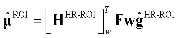
- ⁇ ⁇ ROI H HR ⁇ ROI w T Fw g ⁇ HR ⁇ ROI
- w weighting in a filtered back projection algorithm under fan-beam or cone-beam scanning
- F filtering
- H HR ⁇ ROI w T represents a weighting back-projection process under fan-beam or cone-beam scanning.
- H NR is a system matrix of full-view scanning;
- n NR is random noise;
- ⁇ NR is a linear attenuation coefficient distribution of the normal resolution, which can be NR-ROI divided into two parts: ⁇ NR-ROI is a linear attenuation coefficient distribution of the normal resolution of the ROI, and ⁇ NR- ROI is a linear attenuation coefficient distribution of the normal resolution outside the ROI.
- the ⁇ NR can be reconstructed using a common reconstruction method in the art, so that an estimation image ⁇ NR can be obtained, and ⁇ NR-ROI and ⁇ NR- ROI are correspondingly obtained.
- This step can be carried out using a well-known iterative method in the art or can be carried out through an analytical reconstruction algorithm.
- first image estimation ⁇ ROI of the ROI and first full-view image estimation NR-ROI ⁇ NR-ROI within the ROI can be input into an image generation model to obtain a high-quality high-resolution image ⁇ HR-ROI of the ROI.
- cost function 1 can be defined as a distance between p ⁇ and p HR-ROI : ⁇ 1 ( p ⁇ , p HR-ROI )
- cost function 2 can be defined as a distance between ⁇ ROI and ⁇ ROI : ⁇ 2 ( ⁇ ROI , ⁇ ROI ). Therefore, a ROI projection estimation network can be trained using cost function 1 and cost function 2 which are obtained in this way. For example, training can be achieved by minimizing ⁇ 1 ( ⁇ ROI , ⁇ ROI ) + ⁇ 2 ( p ⁇ , p HR-ROI ).
- cost function 3 can also be defined as a distance between ⁇ HR-ROI and ⁇ ROI : ⁇ 3 ( ⁇ HR-ROI , ⁇ ROI ). Therefore, the image optimization model can also be trained using cost function 3. For example, similar to cost functions 1 and 2, the above training can also be performed by minimizing cost function 3.
- training data can also be obtained on the basis of a projection simulation process of detailed-view and full-view scanning modes.
- high-resolution estimation training data ⁇ train HR ⁇ ROI of the ROI can be obtained by scanning a preset model body or human body and using the conventional reconstruction method.
- the subscript "train" represents data used for training.
- the high-resolution image training data can also be obtained by a digital model body.
- full-view estimation training data ⁇ train NR with a normal resolution can be obtained by scanning a preset model body or human body and using a conventional reconstruction method, or the data can be obtained from a published data source.
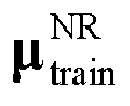
- projection data used in the training data in the embodiments of the present disclosure can be obtained by performing data augmentation processing, such as gray-scale transformation, rotation, transposition and affine transformation, on a high-resolution image and a normal-resolution image of the ROI. Furthermore, data [ p train HR ⁇ ROI , p train NR and ⁇ train HR ⁇ ROI ] is finally formed by pairing to form a training data set.
- the full-view estimation training data and the detailed-view estimation training data can respectively include projection data and image data.
- the ROI projection estimation network can be trained using the training data obtained in this way.
- the projection data p HR-ROI obtained by detailed-view scanning and the projection data p NR obtained by full-view scanning can be used as inputs for the above-mentioned CT reconstruction method, thus obtaining ⁇ HR-ROI serving as the detailed-view image estimation.
- ⁇ NR can be used as the full-view image estimation, or ⁇ NR can be used as an output after being further denoised using a conventional denoising method in the art.
- the temporal bone region can be used as the ROI of the embodiments of the present disclosure. Therefore, the high-resolution detailed-view projection data p ROI HR is obtained, and ⁇ HR-ROI can be obtained by a 3D
- U-Net network a network parameter of which is ⁇ Net1 .
- Input dimensions N, M and L of the network can respectively represent a length and a width of a detector and the number of angles.
- ⁇ HR-ROI H HR ⁇ ROI w T
- w weighting in an FDK algorithm under cone-beam scanning
- F RL filtering
- H HR ⁇ ROI w T is a weighting back projection process under cone-beam scanning such as the FDK algorithm.
- Conventional data preprocessing can be performed on the full-view scanning data, such as background removal, air removal and negative logarithm operation, thus obtaining projection data p NR .
- the FDK algorithm is used to perform reconstruction processing on p NR to obtain image estimation ⁇ NR which can include two parts: estimation data ⁇ NR-ROI inside the ROI and estimation data ⁇ NR- ROI outside the ROI.
- the first full-view image estimation ⁇ NR-ROI within the ROI can be interpolated till it has the same resolution as that of the first image estimation ⁇ ROI of the ROI; and the first image estimation ⁇ ROI of the ROI and the first full-view image estimation ⁇ NR-ROI within the ROI can be input into the image optimization model to obtain high-quality high-resolution image ⁇ HR-ROI of the ROI.
- ⁇ ROI is a ROI true value in simulation.
- the norm distance can be used to express a distance between vectors, and may include 1-norm, namely a sum of absolute values of all elements of the vectors, which is also referred to as the Manhattan distance.
- the norm distance can also include 2-norm, namely 1/2 exponentiation of the sum of squares of all elements of the vectors, which is also referred to as the Euclidean distance.
- a ROI projection estimation network can be trained using cost function 1 and cost function 2 which are obtained in this way. For example, training can be achieved by minimizing ⁇ 1 ( ⁇ ROI , ⁇ ROI ) + ⁇ 2 ( p ⁇ , p HR-ROI ).
- the CT reconstruction solution provided in the embodiments of the present disclosure, by means of acquiring detailed-view scanning data and full-view scanning data and performing ROI projection estimation on the detailed-view scanning data, high-resolution image estimation of a ROI is obtained; reconstruction processing is performed on the full-view projection data to obtain second image estimation; high-resolution image data of the ROI is determined using an image optimization mode according to the first image estimation and the first full-view image estimation, so that a data integrity characteristic of full-view scanning and a high resolution characteristic of detailed-view scanning can be combined to reconstruct a CT image, which not only improves the quality of a reconstructed CT image, but also greatly improves the reconstruction efficiency.
- FIG. 2 is a flow chart of one embodiment of a CT data reconstruction method provided by the present disclosure. As shown in FIG. 2 , the CT data reconstruction method may include the following steps: In S201, detailed-view scanning data and full-view scanning data are acquired.
- Detailed-view scanning data and full-view scanning data can be respectively acquired in the step S201.
- a high-resolution detector can be used to perform centralized scanning on a ROI.
- a normal-resolution detector can also be used as a full-view detector for larger-range scanning. Therefore, for example, in the scenario as shown in FIG. 1 , a scanning beam formed by the normal detector and an X-ray source and a scanning beam formed by the high-resolution detector respectively achieve full-view scanning and detailed-view scanning.
- the above method extends in an axial dimension (perpendicular to a two-dimensional plane in the figure) to form a three-dimensional image.
- the full-view scanning data is usually based on a low resolution, but its scanning range is wider, so that a more complete scanning result can be obtained.
- the detailed-view scanning data is usually based on a high resolution, but its scanning range is focused, so that a scanning result with a higher resolution can be obtained. Therefore, a data integrity characteristic of full-view scanning and a high resolution characteristic of detailed-view scanning can be combined to reconstruct a CT image, which not only improves the quality of a reconstructed CT image, but also greatly improves the reconstruction efficiency.
- H NR is a system matrix of full-view scanning
- n NR is random noise
- ⁇ NR is a linear attenuation coefficient distribution of the normal resolution, which can be NR-ROI divided into two parts: ⁇ ROI is a linear attenuation coefficient distribution of the NR-ROI normal resolution of the ROI, and ⁇ ROI is a linear attenuation coefficient distribution of the normal resolution outside the ROI.
- ROI projection estimation is performed on the detailed-view scanning data to obtain detailed-view projection estimation.
- Projection estimation can be performed in the step S202 on the detailed-view scanning data of the ROI obtained in the step S201.
- estimation data ⁇ HR-ROI ⁇ ⁇ 1 ( p HR-ROI ) of H HR-ROI H HR-ROI ⁇ ROI can be obtained through a ROI projection estimation network model on the basis of p HR-ROI obtained in the step S201, where ⁇ 1 (g) represents an operator of a neural network.
- step S203 reconstruction processing can be performed on the projection data ⁇ HR-ROI of the ROI obtained in the step S202.
- ⁇ ⁇ ROI H HR ⁇ ROI w T Fw g ⁇ HR ⁇ ROI can be used, where w is weighting in a filtered back projection algorithm under fan-beam or cone-beam scanning; F is filtering; and H HR ⁇ ROI w T represents a weighting back projection process under fan-beam or cone-beam scanning, thus obtaining first image estimation ⁇ ROI of the ROI.
- step S204 reconstruction processing is performed on the full-view projection data to obtain first full-view image estimation within the ROI of second estimate image data.
- the full-view scanning data obtained in the step S201 can be reconstructed using a conventional reconstruction method in the art to obtain second image estimation ⁇ NR , and the image estimation may include image estimation ⁇ NR-ROI within the ROI and image estimation ⁇ NR- ROI outside the ROI.
- This step can be carried out using a well-known iteration method in the art or can be carried out through an analytical reconstruction algorithm.
- high-resolution image data of the ROI is determined using an image optimization model according to the first image estimation and the first full-view image estimation.
- first image estimation ⁇ ROI of the ROI and first full-view image estimation ⁇ NR - ROI within the ROI can be input into an image generation algorithm model to obtain a high-quality high-resolution image ⁇ HR-ROI of the ROI.
- cost function 1 can be defined as a distance between p ⁇ and p HR-ROI : ⁇ 1 ( p ⁇ , p HR-ROI )
- cost function 2 can be defined as a distance between ⁇ ROI and ⁇ ROI : ⁇ 2 ( ⁇ ROI , ⁇ ROI ). Therefore, a ROI projection estimation network can be trained using cost function 1 and cost function 2 which are obtained in this way. For example, training can be achieved by minimizing ⁇ 1 ( ⁇ ROI , ⁇ ROI ) + ⁇ 2 ( p ⁇ , p HR-ROI ).
- cost function 3 can also be defined as a distance between ⁇ HR-ROI and ⁇ ROI : ⁇ 3 ( ⁇ HR-ROI , ⁇ ROI ). Therefore, the image generation algorithm model can also be trained using cost function 3. For example, similar to cost functions 1 and 2, the above training can also be performed by minimizing cost function 3.
- training data can also be obtained on the basis of a projection simulation process of detailed-view and full-view scanning modes.
- high-resolution estimation image training data ⁇ train HR ⁇ ROI of the ROI can be obtained by scanning a preset model body or human body and using the conventional reconstruction method.
- the high-resolution image training data can also be obtained by a digital model body.
- full-view estimation training data ⁇ train NR with a normal resolution can be obtained by scanning a preset model body or human body and using a conventional reconstruction method, or the data can be obtained from a published data source.
- data augmentation can be performed on the high-resolution image training data and the normal-resolution full-view estimation training data of the ROI that are obtained in this way, for example, by gray-scale transformation, rotation, shifting and affine transformation.
- data [ p train HR ⁇ ROI , p train NR and ⁇ train HR ⁇ ROI ] is finally formed to form a training data set.
- the projection data p HR-ROI obtained by detailed-view scanning and the projection data p NR obtained by full-view scanning can be used as inputs for the above-mentioned CT data reconstruction method, thus obtaining ⁇ HR-ROI serving as the detailed-view image estimation.
- ⁇ NR can be used as the full-view image estimation, or ⁇ N R can be used as an output after being further denoised using a conventional denoising method in the art.
- the CT data reconstruction solution provided in the embodiments of the present disclosure, by means of acquiring detailed-view scanning data and full-view scanning data and performing ROI projection estimation on the detailed-view scanning data, high-resolution image estimation of a ROI is obtained; reconstruction processing is performed on the full-view projection data to obtain second image estimation; high-resolution image data of the ROI is determined using an image optimization mode according to the first image estimation and the first full-view image estimation, so that a data integrity characteristic of full-view scanning and a high resolution characteristic of detailed-view scanning can be combined to reconstruct a CT image, which not only improves the quality of a reconstructed CT image, but also greatly improves the reconstruction efficiency.
- FIG. 3 is a schematic structural diagram of one embodiment of a CT data reconstruction apparatus provided by the present disclosure, which can be configured for executing the steps of the method as shown in FIG. 2 .
- the CT data reconstruction apparatus may include: an acquisition module 31, an estimation module 32, a first reconstruction module 33, a second reconstruction module 34 and a determination module 35.
- the acquisition module 31 can be configured to acquire detailed-view scanning data and full-view scanning data.
- the acquisition module 31 can be configured to respectively acquire detailed-view scanning data and full-view scanning data.
- a high-resolution detector can be used to perform centralized scanning on a ROI.
- a normal-resolution detector can also be used as a full-view detector for larger-range scanning. Therefore, for example, in the scenario as shown in FIG. 1 , a scanning beam formed by the normal-resolution detector and an X-ray source and a scanning beam formed by the high-resolution detector respectively achieve full-view scanning and detailed-view scanning.
- the above method extends in an axial dimension (perpendicular to a two-dimensional plane in the figure) to form a three-dimensional image.
- the full-view scanning data is usually based on a low resolution, but its scanning range is wider, so that a complete scanning result can be obtained.
- the detailed-view scanning data is usually based on a high resolution, but its scanning range is focused, so that a scanning result of a higher resolution can be obtained. Therefore, a data integrity characteristic of full-view scanning and a high resolution characteristic of detailed-view scanning can be combined to reconstruct a CT image, which not only improves the quality of a reconstructed CT image, but also greatly improves the reconstruction efficiency.
- H NR is a system matrix of full-view scanning
- n NR is random noise
- ⁇ NR is a linear attenuation coefficient distribution of the normal resolution, which can be divided into two parts: ⁇ NR-ROI is a linear attenuation coefficient distribution of the normal resolution of the ROI, and ⁇ NR- ROI is a linear attenuation coefficient distribution of the normal resolution outside the ROI.
- the estimation module 32 can be configured to perform ROI projection estimation on the detailed-view scanning data to obtain the estimation of detailed-view projection.
- the estimation module 32 can perform projection estimation on the detailed-view scanning data of the ROI obtained by the acquisition module 31.
- estimation ⁇ HR-ROI ⁇ ⁇ 1 ( p HR-ROI ) of H HR-ROI ⁇ ROI can be obtained through a ROI projection estimation network model on the basis of p HR-ROI obtained by the acquisition module 31, where ⁇ 1 (g) represents an operator of a neural network.
- the first reconstruction module 33 can be configured to perform analytical reconstruction on the estimation of detailed-view projection to obtain first image estimation of a ROI.
- the first reconstruction module 33 can perform reconstruction on the projection data ⁇ HR-ROI of the ROI obtained by the estimation module 32.
- ⁇ ⁇ ROI H HR ⁇ ROI w T Fw g ⁇ HR ⁇ ROI can be used, where w is weighting in a filtered back projection algorithm under fan-beam or cone-beam scanning; F is filtering; and H HR ⁇ ROI w T represents a weighting back projection process under fan-beam or cone-beam scanning, thus obtaining first image estimation ⁇ ROI of the ROI.
- the second reconstruction module 34 can be configured to perform reconstruction processing on the full-view projection data to obtain second image estimation.
- the second reconstruction module 34 can reconstruct the full-view projection data obtained by the acquisition module 31 using a conventional reconstruction method in the art to obtain second image estimation ⁇ NR , and the image estimation may include image estimation ⁇ NR-ROI within the ROI and image estimation ⁇ NR- ROI outside the ROI. This step can be carried out using a well-known iteration method in the art or can be carried out through an analytical reconstruction algorithm.
- the determination module 35 can be configured to determine high-resolution image data of the ROI using an image optimization model according to the first image estimation and the first full-view image estimation.
- the determination module 35 can input first image estimation ⁇ ROI of the ROI and first full-view image estimation ⁇ NR-ROI within the ROI into an image generation algorithm model to obtain a high-quality high-resolution image ⁇ HR-ROI of the ROI.
- cost function 1 can be defined as a distance between p ⁇ and p HR-ROI : ⁇ 1 ( p ⁇ , p HR-ROI )
- cost function 2 can be defined as a distance between ⁇ ROI and ⁇ ROI : ⁇ 2 ( ⁇ ROI , ⁇ ROI ). Therefore, a ROI projection estimation network can be trained using cost function 1 and cost function 2 which are obtained in this way. For example, training can be achieved by minimizing ⁇ 1 ( ⁇ ROI , ⁇ ROI ) + ⁇ 2 ( p ⁇ , p HR-ROI ).
- cost function 3 can also be defined as a distance between ⁇ HR-ROI ) and ⁇ ROI : ⁇ 3 ( ⁇ HR-ROI , ⁇ ROI ). Therefore, the image optimization model can also be trained using cost function 3. For example, similar to cost functions 1 and 2, the above training can also be performed by minimizing cost function 3.
- training data can also be obtained on the basis of a projection simulation process of detailed-view and full-view scanning modes.
- high-resolution estimation image training data ⁇ train HR ⁇ ROI of the ROI can be obtained by scanning a preset model body or human body and using the conventional reconstruction method.
- the high-resolution image training data can also be obtained by a digital model body.
- full-view estimation training data ⁇ train NR with a normal resolution can be obtained by scanning a preset model body or human body and using a conventional reconstruction method, or the data can be obtained from a published data source.
- data augmentation can be performed on the high-resolution image training data and the normal-resolution full-view estimation training data of the ROI that are obtained in this way, for example, by gray-scale transformation, rotation, shifting and affine transformation.
- data [ p train HR ⁇ ROI , p train NR and ⁇ train HR ⁇ ROI ] is finally formed to form a training data set.
- the projection data p HR-ROI obtained by detailed-view scanning and the projection data p NR obtained by full-view scanning can be used as inputs for the above-mentioned CT data reconstruction method, thus obtaining ⁇ HR-ROI serving as the detailed-view image estimation.
- ⁇ NR can be used as the full-view image estimation, or ⁇ NR can be used as an output after being further denoised using a conventional denoising method in the art.
- the CT data reconstruction solution provided in the embodiments of the present disclosure, by means of acquiring detailed-view scanning data and full-view scanning data and performing ROI projection estimation on the detailed-view scanning data, high-resolution image estimation of a ROI is obtained; reconstruction processing is performed on the full-view projection data to obtain second image estimation; high-resolution image data of the ROI is determined using an image optimization mode according to the first image estimation and the first full-view image estimation, so that a data integrity characteristic of full-view scanning and a high resolution characteristic of detailed-view scanning can be combined to reconstruct a CT image, which not only improves the quality of a reconstructed CT image, but also greatly improves the reconstruction efficiency.
- FIG. 4 is a schematic structural diagram of an electronic device embodiment provided by the present disclosure. As shown in FIG. 4 , the electronic device includes a memory 41 and a processor 42.
- the memory 41 is configured for storing a program.
- the memory 41 may also be configured for storing various other data to support operations on the electronic device. Examples of such data include instructions for any application program or method operated on the electronic device, contact data, phone book data, messages, pictures, videos, and the like.
- the memory 41 may be implemented by any type of volatile or non-volatile storage devices or a combination thereof, such as Static Random Access Memory (SRAM), an Electrically Erasable Programmable Read-Only Memory (EEPROM), a Programming Read-Only Memory (EPROM), a Programmable Read-Only Memory (PROM), a Read-Only Memory (ROM), a magnetic memory, a flash memory, a magnetic disk or an optical disk.
- SRAM Static Random Access Memory
- EEPROM Electrically Erasable Programmable Read-Only Memory
- EPROM Programming Read-Only Memory
- PROM Programmable Read-Only Memory
- ROM Read-Only Memory
- magnetic memory a magnetic memory
- flash memory a magnetic disk or an optical disk.
- the processor 42 is not limited to a Central Processing Unit (CPU), but may also be a Graphics Processing Unit (GPU), a Field Programmable Gate Array (FPGA), an Embedded Neural Network Processing Unit (NPU), or an Artificial Intelligence (AI) chip, and other processing chips.
- the processor 42 is coupled with the memory 41 and executes the program stored in the memory 41.
- the program when run, implements the CT data reconstruction method of the above-mentioned embodiment II.
- the electronic device may further include: a communication component 43, a power supply component 44, an audio component 45, a display 46 and other components. Only some components are schematically shown in FIG. 4 , which does not mean that the electronic device only includes the components shown in FIG. 4 .
- the communication component 43 is configured for facilitating wired or wireless communications between the electronic device and other devices.
- the electronic device may access a wireless network based on a communication standard, such as Wi-Fi, 3G, 4G or 5G, or a combination thereof.
- the communication component 43 receives a broadcast signal or broadcast related information from an external broadcast management system via a broadcast channel.
- the communication component 43 further includes a Near Field Communication (NFC) module to facilitate short-range communications.
- the NFC module may be implemented based on a Radio Frequency Identification (RFID) technology, an Infrared Data Association (IrDA), an Ultra-Wide Band (UWB) technology, a Bluetooth (BT) technology and other technologies.
- RFID Radio Frequency Identification
- IrDA Infrared Data Association
- UWB Ultra-Wide Band
- BT Bluetooth
- the power supply component 44 provides power to various components of the electronic device.
- the power supply component 44 may include a power management system, one or more power supplies, and other components associated with generation, management, and distribution of power for the electronic device.
- the audio component 45 is configured for outputting and/or inputting audio signals.
- the audio component 45 includes a microphone (MIC).
- the microphone is configured for receiving an external audio signal when the electronic device is in an operation mode, such as a calling mode, a recording mode, and a voice recognition mode.
- the received audio signal may be further stored in the memory 41 or transmitted via the communication component 43.
- the audio component 45 further includes a speaker configured for outputting audio signals.
- the display 46 includes a screen which may include a Liquid Crystal Display (LCD) and a Touch Panel (TP). If it includes the TP, the screen may be implemented as a touch screen to receive an input signal from a user.
- the TP includes one or more touch sensors to sense touch, swipe, and gestures on the TP.
- the touch sensor may not only detect a boundary of a touch or swipe action, but also detect duration and pressure related to the touch or swipe operation.
- a program instruction related hardware can be implemented by a program instruction related hardware.
- the aforementioned program can be stored in one computer-readable storage medium.
- the program when executed, executes the steps of the foregoing method embodiments; and the foregoing storage medium includes: a ROM, a RAM, a magnetic disk, or an optical disk and other media that can store program codes.
Landscapes
- Physics & Mathematics (AREA)
- General Physics & Mathematics (AREA)
- Engineering & Computer Science (AREA)
- Theoretical Computer Science (AREA)
- Apparatus For Radiation Diagnosis (AREA)
Abstract
Description
- The present disclosure relates to the technical field of medical devices, in particular to a computerized tomography (CT) reconstruction method and apparatus, an electronic device and a computer-readable storage medium.
- In the medical field, CT has been widely used as a basic inspection method. However, at present, limited by its spatial resolution, CT cannot meet a diagnostic requirement in terms of imaging of a body with fine structures such as the temporal bone, so doctors are unable to use CT as an inspection method when diagnosing minimal hidden lesions, thus affecting the efficacy of CT in clinical application.
- After CT scanning data is obtained, a CT image that can be directly read by doctors or patients can be obtained by CT reconstruction. However, a traditional CT reconstruction method has a high requirement for data during reconstruction using CT scanning data, and incomplete data will often cause artifacts, which severely affects the usage of the CT images.
- Embodiments of the present disclosure provide a CT reconstruction method and apparatus, an electronic device and a computer-readable storage medium, so as to solve the problems of poor image quality of a CT reconstruction and low efficiency in the prior art.
- In order to achieve the above objective, the embodiments of the present disclosure provide a CT reconstruction method, including:
- acquiring detailed-view scanning data and full-view scanning data;
- performing projection estimation of the region of interest (ROI) from the detailed-view scanning data to obtain detailed-view projection;
- performing analytical reconstruction on the detailed-view projection to obtain first image estimation of the ROI;
- performing reconstruction on the full-view projection to obtain first full-view image estimation within the ROI ; and
- determining high-resolution image data of the ROI using an image optimization model according to the first image estimation and the first full-view image estimation.
- The embodiments of the present disclosure also provide a CT reconstruction apparatus, including:
- an acquisition module configured to acquire detailed-view scanning data and full-view scanning data;
- an estimation module configured to perform ROI projection estimation from the detailed-view scanning data to obtain an estimation of detailed-view projection;
- a first reconstruction module configured to perform analytical reconstruction on the estimation of detailed-view projection to obtain first image estimation of an ROI;
- a second reconstruction module configured to perform reconstruction processing on the full-view projection data to obtain first full-view image estimation within the ROI of second image estimation; and
- a determination module configured to determine the high-resolution image of the ROI using an image optimization model according to the first image estimation and the first full-view image estimation.
- The embodiments of the present disclosure also provide an electronic device, including:
- a memory configured for storing a program; and
- a processor configured for running the program stored in the memory, the program, when run, implementing the CT reconstruction method provided by the embodiments of the present disclosure.
- The embodiments of the present disclosure also provide a computer-readable storage medium, which stores a computer program that can be executed by a processor. The program, when executed by the processor, implements the CT reconstruction method provided by the embodiments of the present disclosure.
- According to the CT reconstruction method and apparatus, the electronic device and the computer-readable storage medium, by means of acquiring detailed-view scanning data and full-view scanning data and performing ROI projection estimation on the detailed-view scanning data, high-resolution image estimation of a ROI is obtained; reconstruction is performed on the full-view projection data to obtain second image estimation; high-resolution image of the ROI is determined using an image optimization mode according to the first image estimation and the first full-view image estimation, so that a data integrity characteristic of full-view scanning and a high resolution characteristic of detailed-view scanning can be combined to reconstruct a CT image, which not only improves the quality of a reconstructed CT image, but also greatly improves the reconstruction efficiency.
- The foregoing description is only a summary of the technical solutions of the present disclosure. To know the technical measures of the present disclosure more clearly, the technical solutions can be implemented in accordance with the content of the specification, and to make the foregoing and other objectives, features and advantages of the present disclosure more understandable, specific implementation modes of the present disclosure are exemplified below.
- By reading the detailed description in the preferred specific implementation modes below, various other advantages and benefits will become clear to those of ordinary skill in the art. The accompanying drawings are only used for the purpose of illustrating the preferred implementation modes, and are not considered as a limitation to the present disclosure. Furthermore, throughout the drawings, the same reference numerals are used to denote the same components. In the drawings:
-
FIG. 1 is a schematic diagram of an application scenario of a CT scanning solution of an embodiment of the present disclosure; -
FIG. 2 is a flow chart of one embodiment of a CT scanning method provided by the present disclosure; -
FIG. 3 is a schematic diagram of one embodiment of a CT scanning apparatus provided by the present disclosure; and -
FIG. 4 is a schematic diagram of an electronic device embodiment provided by the present disclosure. - Exemplary embodiments of the present disclosure will be described in more detail below with reference to the accompanying drawings. Although exemplary embodiments of the present disclosure are shown in the drawings, it should be understood that the present disclosure can be implemented in various forms and should not be limited by the embodiments set forth herein. On the contrary, these embodiments are provided to enable a more thorough understanding of the present disclosure and to fully deliver the scope of the present disclosure to those skilled in the art.
- Solutions provided in the embodiments of the present disclosure can be applied to any system with a CT scanning capability, such as a CT scanning system.
FIG. 1 is a schematic diagram of an application scenario of a CT scanning solution provided in an embodiment of the present disclosure. The scenario shown inFIG. 1 is one of examples of scenarios that the technical solutions of the present disclosure can be applied to. - In the medical field, CT has been widely used as a basic inspection method. However, at present, limited by its spatial resolution, CT cannot meet a diagnostic requirement in terms of imaging of a body with fine structures such as the temporal bone, so doctors are unable to use CT as an inspection method when diagnosing minimal hidden lesions, thus affecting the efficacy of CT in clinical application.
- After CT scanning data is obtained, a CT image that can be directly read by doctors or patients can be obtained by CT reconstruction. However, the traditional CT reconstruction method has a high requirement for data during reconstruction using CT scanning data, and incomplete data will often cause artifacts, which severely affects the use effect of the CT scanning data.
- For example, in the scenario as shown in
FIG. 1 , when a temporal bone region of a object to be scanned inFIG. 1 needs to be scanned for imaging, reconstruction is usually performed using an analytical reconstruction algorithm on the basis of projection obtained from scanning data. The analytical reconstruction algorithm usually has a high requirement for data. If data obtained by scanning has low quality, it will cause artifacts or deformation in a reconstructed image. Particularly, this has a serious impact during scanning of a region with fine structures, such as the temporal bone, and even causes the resulted image unusable for diagnosis. As a result, a patient needs to be scanned again, so that the patient will undergo additional radiation exposure. - In the solution provided in the embodiments of the present disclosure, data fusion processing can be performed on the basis of full-view scanning data obtained by a full-view scanning method and detailed-view scanning data. The full-view scanning data is usually based on a low resolution, but its scanning range is wider, so that a complete scanning result can be obtained. The detailed-view data is usually based on a high resolution, but its scanning range is focused, so that a scanning result with a higher resolution can be obtained. Therefore, a data integrity characteristic of full-view scanning and a high resolution characteristic of detailed-view scanning can be combined to reconstruct a CT image, which not only improves the quality of a reconstructed CT image, but also greatly improves the reconstruction efficiency.
- For example, in the embodiments of the present disclosure, ROI can be used to express a targeted region, that is, a region of an object to be scanned. In the embodiments of the present disclosure, a high-resolution detector can be used to perform centralized scanning on the ROI. In the embodiments of the present disclosure, a normal-resolution detector can also be used as a full-view detector for larger-range scanning. Therefore, for example, in the scenario as shown in
FIG. 1 , a scanning beam formed by the normal-resolution detector and an X-ray source and a scanning beam formed by the high-resolution detector respectively achieve full-view scanning and detailed-view scanning. The above method extends in an axial dimension (perpendicular to a two-dimensional plane in the figure) to form a three-dimensional image. - On the basis of the full-view scanning data and the detailed-view scanning data obtained in this way, in the embodiments of the present disclosure, general data preprocessing can be first performed on the detailed-view scanning data, such as background removal, air removal and negative logarithm operation, to obtain HR-ROI projection data which is recorded as p HR-ROI and can be expressed as:

ROI represents a linear attenuation coefficient distribution of the normal resolution outside the ROI; H HR-ROI represents a system matrix of detailed-view scanning; and n HR represents random noise. Estimation data of H HR-ROI µ ROI can be obtained on the basis of input p HR-ROI through a ROI projection estimation network model. ĝ HR-ROI≡ϕ 1(p HR-ROI), where ϕ 1(g) is used for denoting an operator represented by a neural network to be optimized; ĝ HR-ROI is an output of the network; and p HR-ROI is projection data obtained by performing the general data preprocessing on the detailed-view scanning data, such as background removal, air removal and negative logarithm operation. Later, reconstruction operation, i.e.,

- Therefore, the projection data g a = H HR-ROI µ̂ ROI of the target ROI can be obtained. Next, conventional data preprocessing can be similarly performed on the full-view scanning data, such as background removal, air removal and negative logarithm operation, thus obtaining projection data which is recorded as p NR and can be expressed as:

ROI is a linear attenuation coefficient distribution of the normal resolution outside the ROI. Therefore, in the embodiments of the present disclosure, the µ NR can be reconstructed using a common reconstruction method in the art, so that an estimation image µ̂ NR can be obtained, and µ̂ NR-ROI and µ̂ NR-ROI are correspondingly obtained. This step can be carried out using a well-known iterative method in the art or can be carried out through an analytical reconstruction algorithm. For example, when the analytical reconstruction method is used, high-resolution projection data of pixels outside the ROI can be calculated: g b = H NR-ROI µ̂ROI , where H NR-ROI is a system matrix corresponding to the high-resolution detector and normal resolution pixels outside the ROI. - Finally, first image estimation µ̂ ROI of the ROI and first full-view image estimation NR-ROI µ NR-ROI within the ROI can be input into an image generation model to obtain a high-quality high-resolution image µ̂ HR-ROI of the ROI.
- In addition, pixel-by-pixel summation can be performed on first high-resolution projection data g a inside the ROI and second high-resolution projection data g b outside the ROI which are obtained in this way to obtain third high-resolution projection data p̂ = g a + g b of the ROI. Later, cost function 1 can be defined as a distance between p̂ and p HR-ROI : Φ1(p̂,p HR-ROI), and cost function 2 can be defined as a distance between µ̂ ROI and µ̃ ROI : Φ 2( µ̂ ROI, µ̃ ROI). Therefore, a ROI projection estimation network can be trained using cost function 1 and cost function 2 which are obtained in this way. For example, training can be achieved by minimizing Φ 1( µ̂ ROI, µ̃ ROI) + λΦ 2( p̂ ,p HR-ROI).
- In addition, in the embodiments of the present disclosure, after the high-quality high-resolution image of the ROI is obtained, cost function 3 can also be defined as a distance between µ̂ HR-ROI and µ̃ ROI : Φ 3( µ̂ HR-ROI, µ̃ ROI). Therefore, the image optimization model can also be trained using cost function 3. For example, similar to cost functions 1 and 2, the above training can also be performed by minimizing cost function 3.
- In addition, in order to acquire a training data set for training, in the embodiments of the present disclosure, training data can also be obtained on the basis of a projection simulation process of detailed-view and full-view scanning modes. For example, high-resolution estimation training data


- When the temporal bone is subjected to cone-beam CT scanning, a doctor usually needs to clear fine structures of the temporal bone, so that this region should be scanned and imaged at an ultra-high resolution. Therefore, the temporal bone region can be used as the ROI of the embodiments of the present disclosure. Therefore, the high-resolution detailed-view projection data

- U-Net network, a network parameter of which is θ Net1. Input dimensions N, M and L of the network can respectively represent a length and a width of a detector and the number of angles.
- Therefore, first-step reconstruction operation, i.e.,

ROI outside the ROI. Next, high-resolution projection data outside the ROI can be calculated: g b = H HR-ROI µ̂ROI , where H HR-ROI is a system matrix corresponding to the high-resolution detector and normal resolution pixels outside the ROI. - Finally, the first full-view image estimation µ NR-ROI within the ROI can be interpolated till it has the same resolution as that of the first image estimation µ̂ ROI of the ROI; and the first image estimation µ̂ ROI of the ROI and the first full-view image estimation µ NR-ROI within the ROI can be input into the image optimization model to obtain high-quality high-resolution image µ̂ HR-ROI of the ROI.
- In addition, pixel-by-pixel summation can be performed on first high-resolution projection data g a inside the ROI and second high-resolution projection data g b outside the ROI which are obtained in this way to obtain third high-resolution projection data p̂ = g a + g b of the ROI. Later, cost function 1 can be defined as a norm distance between p̂ and p HR-ROI : Φ1(p̂,p HR-ROI) = ∥p̂-p HR-ROI∥, and cost function 2 can be defined as a norm distance between µ̂ ROI and µ̃ ROI : Φ 2( µ̂ ROI, µ̃ ROI) = ∥ µ̂ ROI- µ̃ ROI∥. µ̃ ROI is a ROI true value in simulation. In the embodiments of the present disclosure, the norm distance can be used to express a distance between vectors, and may include 1-norm, namely a sum of absolute values of all elements of the vectors, which is also referred to as the Manhattan distance. The norm distance can also include 2-norm, namely 1/2 exponentiation of the sum of squares of all elements of the vectors, which is also referred to as the Euclidean distance.
- Therefore, a ROI projection estimation network can be trained using cost function 1 and cost function 2 which are obtained in this way. For example, training can be achieved by minimizing Φ 1( µ̂ ROI, µ̃ ROI) + λΦ 2( p̂ , p HR-ROI).
- In addition, in the embodiments of the present disclosure, after the high-quality high-resolution image of the ROI is obtained, cost function 3 can also be defined as a norm distance between µ̂ HR-ROI and µ̃ ROI : Φ 3( µ̂ HR-ROI, µ̃ ROI) = ∥ µ̂ HR-ROI- µ̃ ROI∥ + β ∥E( µ̂ HR-ROI) - E( µ̂ ROI)∥2 , where ∥E( µ̂ HR-ROI) - E( µ̂ ROI)∥2 is CTIS loss cost function. Therefore, the image optimization model can also be trained using cost function 3. For example, similar to cost functions 1 and 2, the above training can also be performed by minimizing cost function 3.
- Therefore, according to the CT reconstruction solution provided in the embodiments of the present disclosure, by means of acquiring detailed-view scanning data and full-view scanning data and performing ROI projection estimation on the detailed-view scanning data, high-resolution image estimation of a ROI is obtained; reconstruction processing is performed on the full-view projection data to obtain second image estimation; high-resolution image data of the ROI is determined using an image optimization mode according to the first image estimation and the first full-view image estimation, so that a data integrity characteristic of full-view scanning and a high resolution characteristic of detailed-view scanning can be combined to reconstruct a CT image, which not only improves the quality of a reconstructed CT image, but also greatly improves the reconstruction efficiency.
- The above embodiment is illustrative of the technical principle and exemplary application framework of the embodiments of the present disclosure. Specific technical solutions of the embodiments of the present disclosure are further described in detail below through multiple embodiments.
-
FIG. 2 is a flow chart of one embodiment of a CT data reconstruction method provided by the present disclosure. As shown inFIG. 2 , the CT data reconstruction method may include the following steps:
In S201, detailed-view scanning data and full-view scanning data are acquired. - Detailed-view scanning data and full-view scanning data can be respectively acquired in the step S201. For example, in the embodiments of the present disclosure, a high-resolution detector can be used to perform centralized scanning on a ROI. In the embodiments of the present disclosure, a normal-resolution detector can also be used as a full-view detector for larger-range scanning. Therefore, for example, in the scenario as shown in
FIG. 1 , a scanning beam formed by the normal detector and an X-ray source and a scanning beam formed by the high-resolution detector respectively achieve full-view scanning and detailed-view scanning. The above method extends in an axial dimension (perpendicular to a two-dimensional plane in the figure) to form a three-dimensional image. - The full-view scanning data is usually based on a low resolution, but its scanning range is wider, so that a more complete scanning result can be obtained. The detailed-view scanning data is usually based on a high resolution, but its scanning range is focused, so that a scanning result with a higher resolution can be obtained. Therefore, a data integrity characteristic of full-view scanning and a high resolution characteristic of detailed-view scanning can be combined to reconstruct a CT image, which not only improves the quality of a reconstructed CT image, but also greatly improves the reconstruction efficiency.
- In addition, prior to the step S201, full-view scanning data, and detailed-view scanning data of the ROI can be firstly acquired; general data preprocessing can be then performed on the detailed-view scanning data, such as background removal, air removal and negative logarithm operation, to obtain projection data which is recorded as p HR-ROI and can be expressed as:

ROI represents a linear attenuation coefficient distribution of the normal resolution outside the ROI; H HR-ROI represents a system matrix of detailed-view scanning; and n HR represents random noise. - Conventional data preprocessing is similarly performed on the full-view scanning data, such as background removal, air removal and negative logarithm operation, thus obtaining projection data which is recorded as p NR and can be expressed as:

- In S202, ROI projection estimation is performed on the detailed-view scanning data to obtain detailed-view projection estimation.
- Projection estimation can be performed in the step S202 on the detailed-view scanning data of the ROI obtained in the step S201. For example, estimation data ĝ HR-ROI ≡ ϕ 1(p HR-ROI) of H HR-ROI H HR-ROI µ ROI can be obtained through a ROI projection estimation network model on the basis of p HR-ROI obtained in the step S201, where ϕ 1(g) represents an operator of a neural network.
- In S203, analytical reconstruction processing is performed on the detailed-view estimation data to obtain first image estimation of the ROI.
- In the step S203, reconstruction processing can be performed on the projection data ĝ HR-ROI of the ROI obtained in the step S202. For example,


- In S204, reconstruction processing is performed on the full-view projection data to obtain first full-view image estimation within the ROI of second estimate image data. In the step S204, the full-view scanning data obtained in the step S201 can be reconstructed using a conventional reconstruction method in the art to obtain second image estimation µ NR , and the image estimation may include image estimation µ̂ NR-ROI within the ROI and image estimation µ̂ NR-
ROI outside the ROI. This step can be carried out using a well-known iteration method in the art or can be carried out through an analytical reconstruction algorithm. - In S205, high-resolution image data of the ROI is determined using an image optimization model according to the first image estimation and the first full-view image estimation.
- In the step S205, first image estimation µ̂ ROI of the ROI and first full-view image estimation µ NR-ROI within the ROI can be input into an image generation algorithm model to obtain a high-quality high-resolution image µ̂ HR-ROI of the ROI.
- In addition, in the embodiments of the present disclosure, after the second image estimation is obtained in the step S204, high-resolution projection data of pixels outside the ROI can be calculated: g b = H HR-
ROI µ̂ROI , where H HR-ROI is a system matrix corresponding to the high-resolution detector and normal resolution pixels outside the ROI. - In addition, pixel-by-pixel summation can be performed on first high-resolution projection data g a inside the ROI and second high-resolution projection data g b outside the ROI which are obtained in this way to obtain third high-resolution projection data p̂ = g a + g b of the ROI. Later, cost function 1 can be defined as a distance between p̂ and p HR-ROI : Φ1(p̂,p HR-ROI), and cost function 2 can be defined as a distance between µ̂ ROI and µ̃ ROI : Φ 2 ( µ̂ ROI, µ̃ ROI). Therefore, a ROI projection estimation network can be trained using cost function 1 and cost function 2 which are obtained in this way. For example, training can be achieved by minimizing Φ 1 ( µ̂ ROI, µ̃ ROI) + λΦ 2( p̂ ,p HR-ROI).
- In addition, in the embodiments of the present disclosure, after the high-quality high-resolution image of the ROI is obtained, cost function 3 can also be defined as a distance between µ̂ HR-ROI and µ̃ ROI : Φ 3( µ̂ HR-ROI, µ̃ ROI). Therefore, the image generation algorithm model can also be trained using cost function 3. For example, similar to cost functions 1 and 2, the above training can also be performed by minimizing cost function 3.
- In addition, in order to acquire a training data set for training, in the embodiments of the present disclosure, training data can also be obtained on the basis of a projection simulation process of detailed-view and full-view scanning modes. For example, high-resolution estimation image training data


- In an actual CT scanning process, the projection data p HR-ROI obtained by detailed-view scanning and the projection data p NR obtained by full-view scanning can be used as inputs for the above-mentioned CT data reconstruction method, thus obtaining µ̂ HR-ROI serving as the detailed-view image estimation. Furthermore, µ̂ NR can be used as the full-view image estimation, or µ̂ NR can be used as an output after being further denoised using a conventional denoising method in the art.
- Therefore, according to the CT data reconstruction solution provided in the embodiments of the present disclosure, by means of acquiring detailed-view scanning data and full-view scanning data and performing ROI projection estimation on the detailed-view scanning data, high-resolution image estimation of a ROI is obtained; reconstruction processing is performed on the full-view projection data to obtain second image estimation; high-resolution image data of the ROI is determined using an image optimization mode according to the first image estimation and the first full-view image estimation, so that a data integrity characteristic of full-view scanning and a high resolution characteristic of detailed-view scanning can be combined to reconstruct a CT image, which not only improves the quality of a reconstructed CT image, but also greatly improves the reconstruction efficiency.
-
FIG. 3 is a schematic structural diagram of one embodiment of a CT data reconstruction apparatus provided by the present disclosure, which can be configured for executing the steps of the method as shown inFIG. 2 . As shown inFIG. 3 , the CT data reconstruction apparatus may include: anacquisition module 31, anestimation module 32, afirst reconstruction module 33, asecond reconstruction module 34 and adetermination module 35. - The
acquisition module 31 can be configured to acquire detailed-view scanning data and full-view scanning data. - The
acquisition module 31 can be configured to respectively acquire detailed-view scanning data and full-view scanning data. For example, in the embodiments of the present disclosure, a high-resolution detector can be used to perform centralized scanning on a ROI. In the embodiments of the present disclosure, a normal-resolution detector can also be used as a full-view detector for larger-range scanning. Therefore, for example, in the scenario as shown inFIG. 1 , a scanning beam formed by the normal-resolution detector and an X-ray source and a scanning beam formed by the high-resolution detector respectively achieve full-view scanning and detailed-view scanning. The above method extends in an axial dimension (perpendicular to a two-dimensional plane in the figure) to form a three-dimensional image. - The full-view scanning data is usually based on a low resolution, but its scanning range is wider, so that a complete scanning result can be obtained. The detailed-view scanning data is usually based on a high resolution, but its scanning range is focused, so that a scanning result of a higher resolution can be obtained. Therefore, a data integrity characteristic of full-view scanning and a high resolution characteristic of detailed-view scanning can be combined to reconstruct a CT image, which not only improves the quality of a reconstructed CT image, but also greatly improves the reconstruction efficiency.
- In addition, the
acquisition module 31 can also first acquire full-view scanning data, and detailed-view scanning data of the ROI, and then perform general data preprocessing on the detailed-view scanning data, such as background removal, air removal and negative logarithm operation, to obtain projection data which is recorded as p HR-ROI and can be expressed as:
ROI represents a linear attenuation coefficient distribution of the normal resolution outside the ROI; H HR-ROI represents a system matrix of detailed-view scanning; and n HR represents random noise. - Conventional data preprocessing is similarly performed on the full-view scanning data, such as background removal, air removal and negative logarithm operation, thus obtaining projection data which is recorded as p NR and can be expressed as:

ROI is a linear attenuation coefficient distribution of the normal resolution outside the ROI. - The
estimation module 32 can be configured to perform ROI projection estimation on the detailed-view scanning data to obtain the estimation of detailed-view projection. Theestimation module 32 can perform projection estimation on the detailed-view scanning data of the ROI obtained by theacquisition module 31. For example, estimation ĝ HR-ROI≡ϕ 1(p HR-ROI) of H HR-ROI µ ROI can be obtained through a ROI projection estimation network model on the basis of p HR-ROI obtained by theacquisition module 31, where ϕ 1(g) represents an operator of a neural network. - The
first reconstruction module 33 can be configured to perform analytical reconstruction on the estimation of detailed-view projection to obtain first image estimation of a ROI. - The
first reconstruction module 33 can perform reconstruction on the projection data ĝ HR-ROI of the ROI obtained by theestimation module 32. For example,

- The
second reconstruction module 34 can be configured to perform reconstruction processing on the full-view projection data to obtain second image estimation. - The
second reconstruction module 34 can reconstruct the full-view projection data obtained by theacquisition module 31 using a conventional reconstruction method in the art to obtain second image estimation µ NR , and the image estimation may include image estimation µ̂ NR-ROI within the ROI and image estimation µ̂ NR-ROI outside the ROI. This step can be carried out using a well-known iteration method in the art or can be carried out through an analytical reconstruction algorithm. - The
determination module 35 can be configured to determine high-resolution image data of the ROI using an image optimization model according to the first image estimation and the first full-view image estimation. - The
determination module 35 can input first image estimation µ̂ ROI of the ROI and first full-view image estimation µ NR-ROI within the ROI into an image generation algorithm model to obtain a high-quality high-resolution image µ̂ HR-ROI of the ROI. In addition, in the embodiments of the present disclosure, after thesecond reconstruction module 34 obtains the second image estimation, high-resolution projection data of pixels outside the ROI can be further calculated: g b = H HR-ROI µ̂ROI , where H NR-ROI is a system matrix corresponding to the high-resolution detector and normal resolution pixels outside the ROI. - In addition, pixel-by-pixel summation can be performed on first high-resolution projection data g a inside the ROI and second high-resolution projection data g b outside the ROI which are obtained in this way to obtain third high-resolution projection data p̂ = g a + g b of the ROI. Later, cost function 1 can be defined as a distance between p̂ and p HR-ROI : Φ1(p̂,p HR-ROI), and cost function 2 can be defined as a distance between µ̂ ROI and µ̃ ROI : Φ 2( µ̂ ROI, µ̃ ROI). Therefore, a ROI projection estimation network can be trained using cost function 1 and cost function 2 which are obtained in this way. For example, training can be achieved by minimizing Φ 1( µ̂ ROI, µ̃ ROI) + λΦ 2( p̂ , p HR-ROI).
- In addition, in the embodiments of the present disclosure, after the high-quality high-resolution image of the ROI is obtained, cost function 3 can also be defined as a distance between µ̂ HR-ROI) and µ̃ ROI : Φ 3( µ̂ HR-ROI, µ̃ ROI). Therefore, the image optimization model can also be trained using cost function 3. For example, similar to cost functions 1 and 2, the above training can also be performed by minimizing cost function 3.
- In addition, in order to acquire a training data set for training, in the embodiments of the present disclosure, training data can also be obtained on the basis of a projection simulation process of detailed-view and full-view scanning modes. For example, high-resolution estimation image training data



- In an actual CT scanning process, the projection data p HR-ROI obtained by detailed-view scanning and the projection data p NR obtained by full-view scanning can be used as inputs for the above-mentioned CT data reconstruction method, thus obtaining µ̂ HR-ROI serving as the detailed-view image estimation. Furthermore, µ̂ NR can be used as the full-view image estimation, or µ̂ NR can be used as an output after being further denoised using a conventional denoising method in the art.
- Therefore, according to the CT data reconstruction solution provided in the embodiments of the present disclosure, by means of acquiring detailed-view scanning data and full-view scanning data and performing ROI projection estimation on the detailed-view scanning data, high-resolution image estimation of a ROI is obtained; reconstruction processing is performed on the full-view projection data to obtain second image estimation; high-resolution image data of the ROI is determined using an image optimization mode according to the first image estimation and the first full-view image estimation, so that a data integrity characteristic of full-view scanning and a high resolution characteristic of detailed-view scanning can be combined to reconstruct a CT image, which not only improves the quality of a reconstructed CT image, but also greatly improves the reconstruction efficiency.
- The internal functions and structures of the CT data reconstruction apparatus are described above. The apparatus can be implemented as an electronic device.
FIG. 4 is a schematic structural diagram of an electronic device embodiment provided by the present disclosure. As shown inFIG. 4 , the electronic device includes amemory 41 and aprocessor 42. - The
memory 41 is configured for storing a program. In addition to the above-mentioned program, thememory 41 may also be configured for storing various other data to support operations on the electronic device. Examples of such data include instructions for any application program or method operated on the electronic device, contact data, phone book data, messages, pictures, videos, and the like. - The
memory 41 may be implemented by any type of volatile or non-volatile storage devices or a combination thereof, such as Static Random Access Memory (SRAM), an Electrically Erasable Programmable Read-Only Memory (EEPROM), a Programming Read-Only Memory (EPROM), a Programmable Read-Only Memory (PROM), a Read-Only Memory (ROM), a magnetic memory, a flash memory, a magnetic disk or an optical disk. - The
processor 42 is not limited to a Central Processing Unit (CPU), but may also be a Graphics Processing Unit (GPU), a Field Programmable Gate Array (FPGA), an Embedded Neural Network Processing Unit (NPU), or an Artificial Intelligence (AI) chip, and other processing chips. Theprocessor 42 is coupled with thememory 41 and executes the program stored in thememory 41. The program, when run, implements the CT data reconstruction method of the above-mentioned embodiment II. - Further, as shown in
FIG. 4 , the electronic device may further include: acommunication component 43, apower supply component 44, anaudio component 45, adisplay 46 and other components. Only some components are schematically shown inFIG. 4 , which does not mean that the electronic device only includes the components shown inFIG. 4 . - The
communication component 43 is configured for facilitating wired or wireless communications between the electronic device and other devices. The electronic device may access a wireless network based on a communication standard, such as Wi-Fi, 3G, 4G or 5G, or a combination thereof. In one exemplary example, thecommunication component 43 receives a broadcast signal or broadcast related information from an external broadcast management system via a broadcast channel. In one exemplary embodiment, thecommunication component 43 further includes a Near Field Communication (NFC) module to facilitate short-range communications. For example, the NFC module may be implemented based on a Radio Frequency Identification (RFID) technology, an Infrared Data Association (IrDA), an Ultra-Wide Band (UWB) technology, a Bluetooth (BT) technology and other technologies. - The
power supply component 44 provides power to various components of the electronic device. Thepower supply component 44 may include a power management system, one or more power supplies, and other components associated with generation, management, and distribution of power for the electronic device. - The
audio component 45 is configured for outputting and/or inputting audio signals. For example, theaudio component 45 includes a microphone (MIC). The microphone is configured for receiving an external audio signal when the electronic device is in an operation mode, such as a calling mode, a recording mode, and a voice recognition mode. The received audio signal may be further stored in thememory 41 or transmitted via thecommunication component 43. In some examples, theaudio component 45 further includes a speaker configured for outputting audio signals. - The
display 46 includes a screen which may include a Liquid Crystal Display (LCD) and a Touch Panel (TP). If it includes the TP, the screen may be implemented as a touch screen to receive an input signal from a user. The TP includes one or more touch sensors to sense touch, swipe, and gestures on the TP. The touch sensor may not only detect a boundary of a touch or swipe action, but also detect duration and pressure related to the touch or swipe operation. - Those of ordinary skill in the art can understand that all or part of the steps in the foregoing method embodiments can be implemented by a program instruction related hardware. The aforementioned program can be stored in one computer-readable storage medium. The program, when executed, executes the steps of the foregoing method embodiments; and the foregoing storage medium includes: a ROM, a RAM, a magnetic disk, or an optical disk and other media that can store program codes.
- It should be finally noted that the above various embodiments are only used to describe the technical solutions of the present invention, and not intended to limit the present invention. Although the present invention has been described in detail with reference to the foregoing embodiments, those ordinarily skilled in the art should understand that they can still modify the technical solutions described in all the foregoing embodiments, or equivalently replace some or all of the technical features, and these modifications or replacements do not depart the essences of the corresponding technical solutions from the scope of the technical solutions of all the embodiments of the present invention.
Claims (10)
- A computerized tomography (CT) data reconstruction method, comprising:acquiring detailed-view scanning data and full-view scanning data;performing ROI projection estimation on the detailed-view scanning data to obtain detailed-view estimation data;performing analytical reconstruction processing on the detailed-view estimation data to obtain first image estimation of a ROI;performing reconstruction processing on the full-view projection data, to obtain first full-view image estimation within the ROI of second estimate image data; anddetermining high-resolution image data of the ROI using an image optimization model according to the first image estimation and the first full-view image estimation.
- The CT reconstruction method according to claim 1, further comprising:calculating first high-resolution projection data within the ROI according to the first image estimation;calculating second high-resolution projection data beyond the ROI according to the second image estimation; anddetermining third high-definition projection data of the ROI according to the first high-resolution projection data and the second high-resolution projection data.
- The CT reconstruction method according to claim 2, wherein a projection estimation model is used for the projection estimation, and the method further comprises:optimizing the projection estimation model using a first cost function and a second cost function,wherein the first cost function is a norm distance between the third high-resolution projection data and the detailed-view projection data, and the second cost function is a norm distance between the first image estimation and the second image estimation.
- The CT reconstruction method according to claim 3, further comprising: calculating a third cost function according to the high-resolution image data; and
optimizing the image optimization model using the third cost function on the basis of the projection estimation model. - The CT reconstruction method according to claim 2, wherein determining third high-definition projection data of the ROI according to the first high-resolution projection data and the second high-resolution projection data comprises:
obtaining the third high-resolution projection data of the ROI by means of performing pixel-by-pixel summation processing on the first high-resolution projection data and the second high-resolution projection data. - The CT reconstruction method according to claim 1, further comprising:acquiring full-view data and detailed-view data of a predetermined reference object for training;obtaining training data of full-view estimation and detailed-view estimation according to the full-view scanning data and the detailed-view scanning data;performing data augmentation processing on the training data of full-view estimation and detailed-view estimation to obtain augmented data of full-view image estimation and detailed-view image estimation;performing fusion processing on the augmented data of full-view image estimation with the augmented data of detailed-view image estimation to obtain fused image data for training;respectively performing detailed-view and full-view simulation on the fused image data for training to obtain training data of full-view CT image and detailed-view CT image; andperforming training on a neural network model using the training data of full-view CT image and the detailed-view CT image to obtain a first neural network model.
- The CT reconstruction method according to claim 1, further comprising:calculating a third cost function according to the high-resolution image data; andperforming optimization on the image optimization model using the third cost function.
- A CT reconstruction apparatus, comprising:an acquisition module configured to acquire detailed-view scanning data and full-view scanning data;an estimation module configured to perform ROI projection estimation on the detailed-view projection data to obtain detailed-view estimation data;a first reconstruction module configured to perform analytical reconstruction processing on the detailed-view estimation data to obtain first image estimation of a ROI;a second reconstruction module configured to perform reconstruction processing on the full-view projection data to obtain first full-view image estimation within the ROI of second image estimate; anda determination module configured to determine high-resolution image data of the ROI using an image optimization model according to the first image estimation and the first full-view image estimation.
- An electronic device, comprising:a memory configured for storing a program; anda processor configured for running the program stored in the memory to implement the CT reconstruction method according to any one of claims 1 to 7.
- A computer-readable storage medium which stores a computer program executed by a processor, wherein the program, when executed by the processor, implements the CT reconstruction method according to any one of claims 1 to 7.
Applications Claiming Priority (1)
| Application Number | Priority Date | Filing Date | Title |
|---|---|---|---|
| CN202111574601.XA CN114782566B (en) | 2021-12-21 | 2021-12-21 | CT data reconstruction method and device, electronic equipment and computer-readable storage medium |
Publications (2)
| Publication Number | Publication Date |
|---|---|
| EP4202839A1 true EP4202839A1 (en) | 2023-06-28 |
| EP4202839B1 EP4202839B1 (en) | 2025-10-08 |
Family
ID=82424145
Family Applications (1)
| Application Number | Title | Priority Date | Filing Date |
|---|---|---|---|
| EP22213116.1A Active EP4202839B1 (en) | 2021-12-21 | 2022-12-13 | Ct data reconstruction method and apparatus, electronic device and computer-readable storage medium |
Country Status (2)
| Country | Link |
|---|---|
| EP (1) | EP4202839B1 (en) |
| CN (1) | CN114782566B (en) |
Cited By (1)
| Publication number | Priority date | Publication date | Assignee | Title |
|---|---|---|---|---|
| CN119741204A (en) * | 2024-12-10 | 2025-04-01 | 西北工业大学 | Micro-scanning super-resolution reconstruction method and device for interlaced coded infrared dual-band images |
Families Citing this family (1)
| Publication number | Priority date | Publication date | Assignee | Title |
|---|---|---|---|---|
| CN117456025B (en) * | 2023-10-18 | 2024-11-26 | 赛诺威盛医疗科技(扬州)有限公司 | Image generation method, device, equipment and storage medium |
Citations (1)
| Publication number | Priority date | Publication date | Assignee | Title |
|---|---|---|---|---|
| US20210007694A1 (en) * | 2019-07-11 | 2021-01-14 | Canon Medical Systems Corporation | Apparatus and method combining deep learning (dl) with an x-ray computed tomography (ct) scanner having a multi-resolution detector |
Family Cites Families (7)
| Publication number | Priority date | Publication date | Assignee | Title |
|---|---|---|---|---|
| CN104644200B (en) * | 2013-11-25 | 2019-02-19 | Ge医疗系统环球技术有限公司 | Method and apparatus for reducing artifacts in computed tomography image reconstruction |
| WO2019128660A1 (en) * | 2017-12-29 | 2019-07-04 | 清华大学 | Method and device for training neural network, image processing method and device and storage medium |
| US11175242B2 (en) * | 2018-03-20 | 2021-11-16 | Fei Company | Geometric alignment, sample motion correction, and intensity normalization of computed tomography projections using pi-line optimization |
| CN108898658A (en) * | 2018-05-15 | 2018-11-27 | 清华大学 | Three-dimensional geometry and intrinsic composition method for reconstructing and device based on shadow optimization |
| CN109523605A (en) * | 2018-11-29 | 2019-03-26 | 上海联影医疗科技有限公司 | A kind of method, apparatus, equipment and the medium of CT image reconstruction |
| JP7534038B2 (en) * | 2018-11-30 | 2024-08-14 | アキュレイ インコーポレイテッド | Asymmetric scatter fitting for optimal panel readout in cone-beam computed tomography |
| CN111968110B (en) * | 2020-09-02 | 2023-12-22 | 广州海兆印丰信息科技有限公司 | CT imaging method, device, storage medium and computer equipment |
-
2021
- 2021-12-21 CN CN202111574601.XA patent/CN114782566B/en active Active
-
2022
- 2022-12-13 EP EP22213116.1A patent/EP4202839B1/en active Active
Patent Citations (1)
| Publication number | Priority date | Publication date | Assignee | Title |
|---|---|---|---|---|
| US20210007694A1 (en) * | 2019-07-11 | 2021-01-14 | Canon Medical Systems Corporation | Apparatus and method combining deep learning (dl) with an x-ray computed tomography (ct) scanner having a multi-resolution detector |
Non-Patent Citations (1)
| Title |
|---|
| LI MENGZHOU ET AL: "High-resolution interior tomography with a deep neural network trained on a low-resolution dataset", PROCEEDINGS OF THE SPIE, SPIE, US, vol. 11840, 9 September 2021 (2021-09-09), pages 1184018 - 1184018, XP060149853, ISSN: 0277-786X, ISBN: 978-1-5106-5738-0, DOI: 10.1117/12.2594286 * |
Cited By (2)
| Publication number | Priority date | Publication date | Assignee | Title |
|---|---|---|---|---|
| CN119741204A (en) * | 2024-12-10 | 2025-04-01 | 西北工业大学 | Micro-scanning super-resolution reconstruction method and device for interlaced coded infrared dual-band images |
| CN119741204B (en) * | 2024-12-10 | 2025-09-23 | 西北工业大学 | Micro-scanning super-resolution reconstruction method and device for interlaced coded infrared dual-band images |
Also Published As
| Publication number | Publication date |
|---|---|
| CN114782566A (en) | 2022-07-22 |
| EP4202839B1 (en) | 2025-10-08 |
| CN114782566B (en) | 2023-03-10 |
Similar Documents
| Publication | Publication Date | Title |
|---|---|---|
| US11756164B2 (en) | System and method for image correction | |
| CN112770838B (en) | System and method for image enhancement using self-focused deep learning | |
| US9324172B2 (en) | Method of overlap-dependent image stitching for images captured using a capsule camera | |
| JP2023540910A (en) | Connected Machine Learning Model with Collaborative Training for Lesion Detection | |
| CN102024251B (en) | System and method for multi-image based virtual non-contrast image enhancement for dual source CT | |
| EP4202839A1 (en) | Ct data reconstruction method and apparatus, electronic device and computer-readable storage medium | |
| CN110852993B (en) | Imaging method and equipment under the action of contrast agent | |
| US10032295B2 (en) | Tomography apparatus and method of processing tomography image | |
| US20210074034A1 (en) | Methods and apparatus for neural network based image reconstruction | |
| US10013778B2 (en) | Tomography apparatus and method of reconstructing tomography image by using the tomography apparatus | |
| JP7566696B2 (en) | IMAGE PROCESSING APPARATUS, IMAGE PROCESSING METHOD, LEARNING APPARATUS, LEARNING METHOD, AND PROGRAM | |
| EP4201338B1 (en) | Ct scanning method and system, electronic device, and computer-readable storage medium | |
| US20230419455A1 (en) | System and method for image correction | |
| CN114913259B (en) | Truncation artifact correction method, CT image correction method, device and medium | |
| US8805122B1 (en) | System, method, and computer-readable medium for interpolating spatially transformed volumetric medical image data | |
| CN116596810A (en) | A method for automatic enhancement of spinal endoscopic images | |
| US10565748B2 (en) | Medical imaging apparatus and method of operating the same | |
| KR20230121364A (en) | Artifacts reduction method in sparse-view computed tomography | |
| Nanthini et al. | A DL-DeNoiseNet Framework for Robust Image Denoising and Artifact Reduction in Medical Image Diagnostics | |
| Kaur et al. | Advanced Methods and Approaches in Image Reconstruction | |
| Choi et al. | Metal artifact reduction algorithm with conditional latent diffusion model for dental cone‐beam CT | |
| CN121304500B (en) | A method, system, and related apparatus for image correction of SPECT images. | |
| CN106875342B (en) | A method and device for processing computerized tomography images | |
| US20260120274A1 (en) | Methods and apparatus for histo-projection based image reconstruction using deep learning processes | |
| Sarvaiya et al. | Channel attention network for wireless capsule endoscopy image super-resolution |
Legal Events
| Date | Code | Title | Description |
|---|---|---|---|
| PUAI | Public reference made under article 153(3) epc to a published international application that has entered the european phase |
Free format text: ORIGINAL CODE: 0009012 |
|
| STAA | Information on the status of an ep patent application or granted ep patent |
Free format text: STATUS: REQUEST FOR EXAMINATION WAS MADE |
|
| 17P | Request for examination filed |
Effective date: 20221213 |
|
| AK | Designated contracting states |
Kind code of ref document: A1 Designated state(s): AL AT BE BG CH CY CZ DE DK EE ES FI FR GB GR HR HU IE IS IT LI LT LU LV MC ME MK MT NL NO PL PT RO RS SE SI SK SM TR |
|
| GRAP | Despatch of communication of intention to grant a patent |
Free format text: ORIGINAL CODE: EPIDOSNIGR1 |
|
| STAA | Information on the status of an ep patent application or granted ep patent |
Free format text: STATUS: GRANT OF PATENT IS INTENDED |
|
| INTG | Intention to grant announced |
Effective date: 20250430 |
|
| GRAS | Grant fee paid |
Free format text: ORIGINAL CODE: EPIDOSNIGR3 |
|
| GRAA | (expected) grant |
Free format text: ORIGINAL CODE: 0009210 |
|
| STAA | Information on the status of an ep patent application or granted ep patent |
Free format text: STATUS: THE PATENT HAS BEEN GRANTED |
|
| RAP1 | Party data changed (applicant data changed or rights of an application transferred) |
Owner name: LARGEV INSTRUMENT CORP., LTD. |
|
| AK | Designated contracting states |
Kind code of ref document: B1 Designated state(s): AL AT BE BG CH CY CZ DE DK EE ES FI FR GB GR HR HU IE IS IT LI LT LU LV MC ME MK MT NL NO PL PT RO RS SE SI SK SM TR |
|
| REG | Reference to a national code |
Ref country code: GB Ref legal event code: FG4D Ref country code: CH Ref legal event code: F10 Free format text: ST27 STATUS EVENT CODE: U-0-0-F10-F00 (AS PROVIDED BY THE NATIONAL OFFICE) Effective date: 20251008 |
|
| REG | Reference to a national code |
Ref country code: DE Ref legal event code: R096 Ref document number: 602022022624 Country of ref document: DE |
|
| REG | Reference to a national code |
Ref country code: IE Ref legal event code: FG4D |
|
| PGFP | Annual fee paid to national office [announced via postgrant information from national office to epo] |
Ref country code: AT Payment date: 20260113 Year of fee payment: 4 |
|
| PGFP | Annual fee paid to national office [announced via postgrant information from national office to epo] |
Ref country code: FR Payment date: 20251103 Year of fee payment: 4 |
|
| REG | Reference to a national code |
Ref country code: NL Ref legal event code: MP Effective date: 20251008 |
|
| REG | Reference to a national code |
Ref country code: AT Ref legal event code: MK05 Ref document number: 1845486 Country of ref document: AT Kind code of ref document: T Effective date: 20251008 |
|
| PG25 | Lapsed in a contracting state [announced via postgrant information from national office to epo] |
Ref country code: NL Free format text: LAPSE BECAUSE OF FAILURE TO SUBMIT A TRANSLATION OF THE DESCRIPTION OR TO PAY THE FEE WITHIN THE PRESCRIBED TIME-LIMIT Effective date: 20251008 |
|
| PG25 | Lapsed in a contracting state [announced via postgrant information from national office to epo] |
Ref country code: ES Free format text: LAPSE BECAUSE OF FAILURE TO SUBMIT A TRANSLATION OF THE DESCRIPTION OR TO PAY THE FEE WITHIN THE PRESCRIBED TIME-LIMIT Effective date: 20251008 |
|
| REG | Reference to a national code |
Ref country code: LT Ref legal event code: MG9D |
|
| PG25 | Lapsed in a contracting state [announced via postgrant information from national office to epo] |
Ref country code: NO Free format text: LAPSE BECAUSE OF FAILURE TO SUBMIT A TRANSLATION OF THE DESCRIPTION OR TO PAY THE FEE WITHIN THE PRESCRIBED TIME-LIMIT Effective date: 20260108 |
|
| PG25 | Lapsed in a contracting state [announced via postgrant information from national office to epo] |
Ref country code: AT Free format text: LAPSE BECAUSE OF FAILURE TO SUBMIT A TRANSLATION OF THE DESCRIPTION OR TO PAY THE FEE WITHIN THE PRESCRIBED TIME-LIMIT Effective date: 20251008 Ref country code: HR Free format text: LAPSE BECAUSE OF FAILURE TO SUBMIT A TRANSLATION OF THE DESCRIPTION OR TO PAY THE FEE WITHIN THE PRESCRIBED TIME-LIMIT Effective date: 20251008 Ref country code: FI Free format text: LAPSE BECAUSE OF FAILURE TO SUBMIT A TRANSLATION OF THE DESCRIPTION OR TO PAY THE FEE WITHIN THE PRESCRIBED TIME-LIMIT Effective date: 20251008 |
|
| PG25 | Lapsed in a contracting state [announced via postgrant information from national office to epo] |
Ref country code: RS Free format text: LAPSE BECAUSE OF FAILURE TO SUBMIT A TRANSLATION OF THE DESCRIPTION OR TO PAY THE FEE WITHIN THE PRESCRIBED TIME-LIMIT Effective date: 20260108 |
|
| PG25 | Lapsed in a contracting state [announced via postgrant information from national office to epo] |
Ref country code: IS Free format text: LAPSE BECAUSE OF FAILURE TO SUBMIT A TRANSLATION OF THE DESCRIPTION OR TO PAY THE FEE WITHIN THE PRESCRIBED TIME-LIMIT Effective date: 20260208 |
|
| PG25 | Lapsed in a contracting state [announced via postgrant information from national office to epo] |
Ref country code: PT Free format text: LAPSE BECAUSE OF FAILURE TO SUBMIT A TRANSLATION OF THE DESCRIPTION OR TO PAY THE FEE WITHIN THE PRESCRIBED TIME-LIMIT Effective date: 20260209 |
|
| PG25 | Lapsed in a contracting state [announced via postgrant information from national office to epo] |
Ref country code: PL Free format text: LAPSE BECAUSE OF FAILURE TO SUBMIT A TRANSLATION OF THE DESCRIPTION OR TO PAY THE FEE WITHIN THE PRESCRIBED TIME-LIMIT Effective date: 20251008 |
|
| PG25 | Lapsed in a contracting state [announced via postgrant information from national office to epo] |
Ref country code: LV Free format text: LAPSE BECAUSE OF FAILURE TO SUBMIT A TRANSLATION OF THE DESCRIPTION OR TO PAY THE FEE WITHIN THE PRESCRIBED TIME-LIMIT Effective date: 20251008 |