EP4202487A1 - Uwb device and control method thereof - Google Patents
Uwb device and control method thereof Download PDFInfo
- Publication number
- EP4202487A1 EP4202487A1 EP22215848.7A EP22215848A EP4202487A1 EP 4202487 A1 EP4202487 A1 EP 4202487A1 EP 22215848 A EP22215848 A EP 22215848A EP 4202487 A1 EP4202487 A1 EP 4202487A1
- Authority
- EP
- European Patent Office
- Prior art keywords
- ranging
- processor
- standby
- uwb
- count
- Prior art date
- Legal status (The legal status is an assumption and is not a legal conclusion. Google has not performed a legal analysis and makes no representation as to the accuracy of the status listed.)
- Granted
Links
Images


Classifications
-
- G—PHYSICS
- G01—MEASURING; TESTING
- G01S—RADIO DIRECTION-FINDING; RADIO NAVIGATION; DETERMINING DISTANCE OR VELOCITY BY USE OF RADIO WAVES; LOCATING OR PRESENCE-DETECTING BY USE OF THE REFLECTION OR RERADIATION OF RADIO WAVES; ANALOGOUS ARRANGEMENTS USING OTHER WAVES
- G01S5/00—Position-fixing by co-ordinating two or more direction or position line determinations; Position-fixing by co-ordinating two or more distance determinations
- G01S5/01—Determining conditions which influence positioning, e.g. radio environment, state of motion or energy consumption
- G01S5/019—Energy consumption
-
- G—PHYSICS
- G07—CHECKING-DEVICES
- G07C—TIME OR ATTENDANCE REGISTERS; REGISTERING OR INDICATING THE WORKING OF MACHINES; GENERATING RANDOM NUMBERS; VOTING OR LOTTERY APPARATUS; ARRANGEMENTS, SYSTEMS OR APPARATUS FOR CHECKING NOT PROVIDED FOR ELSEWHERE
- G07C9/00—Individual registration on entry or exit
- G07C9/00174—Electronically operated locks; Circuits therefor; Nonmechanical keys therefor, e.g. passive or active electrical keys or other data carriers without mechanical keys
- G07C9/00309—Electronically operated locks; Circuits therefor; Nonmechanical keys therefor, e.g. passive or active electrical keys or other data carriers without mechanical keys operated with bidirectional data transmission between data carrier and locks
-
- G—PHYSICS
- G01—MEASURING; TESTING
- G01S—RADIO DIRECTION-FINDING; RADIO NAVIGATION; DETERMINING DISTANCE OR VELOCITY BY USE OF RADIO WAVES; LOCATING OR PRESENCE-DETECTING BY USE OF THE REFLECTION OR RERADIATION OF RADIO WAVES; ANALOGOUS ARRANGEMENTS USING OTHER WAVES
- G01S11/00—Systems for determining distance or velocity not using reflection or reradiation
- G01S11/02—Systems for determining distance or velocity not using reflection or reradiation using radio waves
-
- H—ELECTRICITY
- H04—ELECTRIC COMMUNICATION TECHNIQUE
- H04W—WIRELESS COMMUNICATION NETWORKS
- H04W52/00—Power management, e.g. Transmission Power Control [TPC] or power classes
- H04W52/02—Power saving arrangements
- H04W52/0209—Power saving arrangements in terminal devices
- H04W52/0261—Power saving arrangements in terminal devices managing power supply demand, e.g. depending on battery level
-
- G—PHYSICS
- G01—MEASURING; TESTING
- G01S—RADIO DIRECTION-FINDING; RADIO NAVIGATION; DETERMINING DISTANCE OR VELOCITY BY USE OF RADIO WAVES; LOCATING OR PRESENCE-DETECTING BY USE OF THE REFLECTION OR RERADIATION OF RADIO WAVES; ANALOGOUS ARRANGEMENTS USING OTHER WAVES
- G01S13/00—Systems using the reflection or reradiation of radio waves, e.g. radar systems; Analogous systems using reflection or reradiation of waves whose nature or wavelength is irrelevant or unspecified
- G01S13/02—Systems using reflection of radio waves, e.g. primary radar systems; Analogous systems
- G01S13/0209—Systems with very large relative bandwidth, i.e. larger than 10 %, e.g. baseband, pulse, carrier-free, ultrawideband
-
- G—PHYSICS
- G01—MEASURING; TESTING
- G01S—RADIO DIRECTION-FINDING; RADIO NAVIGATION; DETERMINING DISTANCE OR VELOCITY BY USE OF RADIO WAVES; LOCATING OR PRESENCE-DETECTING BY USE OF THE REFLECTION OR RERADIATION OF RADIO WAVES; ANALOGOUS ARRANGEMENTS USING OTHER WAVES
- G01S5/00—Position-fixing by co-ordinating two or more direction or position line determinations; Position-fixing by co-ordinating two or more distance determinations
- G01S5/02—Position-fixing by co-ordinating two or more direction or position line determinations; Position-fixing by co-ordinating two or more distance determinations using radio waves
- G01S5/0205—Details
-
- H—ELECTRICITY
- H04—ELECTRIC COMMUNICATION TECHNIQUE
- H04W—WIRELESS COMMUNICATION NETWORKS
- H04W4/00—Services specially adapted for wireless communication networks; Facilities therefor
- H04W4/02—Services making use of location information
- H04W4/023—Services making use of location information using mutual or relative location information between multiple location based services [LBS] targets or of distance thresholds
-
- H—ELECTRICITY
- H04—ELECTRIC COMMUNICATION TECHNIQUE
- H04W—WIRELESS COMMUNICATION NETWORKS
- H04W52/00—Power management, e.g. Transmission Power Control [TPC] or power classes
- H04W52/02—Power saving arrangements
- H04W52/0209—Power saving arrangements in terminal devices
- H04W52/0251—Power saving arrangements in terminal devices using monitoring of local events, e.g. events related to user activity
- H04W52/0258—Power saving arrangements in terminal devices using monitoring of local events, e.g. events related to user activity controlling an operation mode according to history or models of usage information, e.g. activity schedule or time of day
-
- H—ELECTRICITY
- H04—ELECTRIC COMMUNICATION TECHNIQUE
- H04W—WIRELESS COMMUNICATION NETWORKS
- H04W52/00—Power management, e.g. Transmission Power Control [TPC] or power classes
- H04W52/04—Transmission power control [TPC]
- H04W52/38—TPC being performed in particular situations
-
- G—PHYSICS
- G01—MEASURING; TESTING
- G01S—RADIO DIRECTION-FINDING; RADIO NAVIGATION; DETERMINING DISTANCE OR VELOCITY BY USE OF RADIO WAVES; LOCATING OR PRESENCE-DETECTING BY USE OF THE REFLECTION OR RERADIATION OF RADIO WAVES; ANALOGOUS ARRANGEMENTS USING OTHER WAVES
- G01S13/00—Systems using the reflection or reradiation of radio waves, e.g. radar systems; Analogous systems using reflection or reradiation of waves whose nature or wavelength is irrelevant or unspecified
- G01S13/74—Systems using reradiation of radio waves, e.g. secondary radar systems; Analogous systems
- G01S13/76—Systems using reradiation of radio waves, e.g. secondary radar systems; Analogous systems wherein pulse-type signals are transmitted
- G01S13/765—Systems using reradiation of radio waves, e.g. secondary radar systems; Analogous systems wherein pulse-type signals are transmitted with exchange of information between interrogator and responder
-
- G—PHYSICS
- G01—MEASURING; TESTING
- G01S—RADIO DIRECTION-FINDING; RADIO NAVIGATION; DETERMINING DISTANCE OR VELOCITY BY USE OF RADIO WAVES; LOCATING OR PRESENCE-DETECTING BY USE OF THE REFLECTION OR RERADIATION OF RADIO WAVES; ANALOGOUS ARRANGEMENTS USING OTHER WAVES
- G01S5/00—Position-fixing by co-ordinating two or more direction or position line determinations; Position-fixing by co-ordinating two or more distance determinations
- G01S5/01—Determining conditions which influence positioning, e.g. radio environment, state of motion or energy consumption
-
- G—PHYSICS
- G01—MEASURING; TESTING
- G01S—RADIO DIRECTION-FINDING; RADIO NAVIGATION; DETERMINING DISTANCE OR VELOCITY BY USE OF RADIO WAVES; LOCATING OR PRESENCE-DETECTING BY USE OF THE REFLECTION OR RERADIATION OF RADIO WAVES; ANALOGOUS ARRANGEMENTS USING OTHER WAVES
- G01S5/00—Position-fixing by co-ordinating two or more direction or position line determinations; Position-fixing by co-ordinating two or more distance determinations
- G01S5/02—Position-fixing by co-ordinating two or more direction or position line determinations; Position-fixing by co-ordinating two or more distance determinations using radio waves
-
- G—PHYSICS
- G07—CHECKING-DEVICES
- G07C—TIME OR ATTENDANCE REGISTERS; REGISTERING OR INDICATING THE WORKING OF MACHINES; GENERATING RANDOM NUMBERS; VOTING OR LOTTERY APPARATUS; ARRANGEMENTS, SYSTEMS OR APPARATUS FOR CHECKING NOT PROVIDED FOR ELSEWHERE
- G07C9/00—Individual registration on entry or exit
- G07C9/00174—Electronically operated locks; Circuits therefor; Nonmechanical keys therefor, e.g. passive or active electrical keys or other data carriers without mechanical keys
- G07C9/00309—Electronically operated locks; Circuits therefor; Nonmechanical keys therefor, e.g. passive or active electrical keys or other data carriers without mechanical keys operated with bidirectional data transmission between data carrier and locks
- G07C2009/00365—Electronically operated locks; Circuits therefor; Nonmechanical keys therefor, e.g. passive or active electrical keys or other data carriers without mechanical keys operated with bidirectional data transmission between data carrier and locks in combination with a wake-up circuit
- G07C2009/00373—Electronically operated locks; Circuits therefor; Nonmechanical keys therefor, e.g. passive or active electrical keys or other data carriers without mechanical keys operated with bidirectional data transmission between data carrier and locks in combination with a wake-up circuit whereby the wake-up circuit is situated in the lock
-
- Y—GENERAL TAGGING OF NEW TECHNOLOGICAL DEVELOPMENTS; GENERAL TAGGING OF CROSS-SECTIONAL TECHNOLOGIES SPANNING OVER SEVERAL SECTIONS OF THE IPC; TECHNICAL SUBJECTS COVERED BY FORMER USPC CROSS-REFERENCE ART COLLECTIONS [XRACs] AND DIGESTS
- Y02—TECHNOLOGIES OR APPLICATIONS FOR MITIGATION OR ADAPTATION AGAINST CLIMATE CHANGE
- Y02D—CLIMATE CHANGE MITIGATION TECHNOLOGIES IN INFORMATION AND COMMUNICATION TECHNOLOGIES [ICT], I.E. INFORMATION AND COMMUNICATION TECHNOLOGIES AIMING AT THE REDUCTION OF THEIR OWN ENERGY USE
- Y02D30/00—Reducing energy consumption in communication networks
- Y02D30/70—Reducing energy consumption in communication networks in wireless communication networks
Definitions
- Exemplary embodiments of the present disclosure relate to an ultra-wideband (UWB) device and a control method thereof, and more particularly, to a UWB device and a control method thereof, wherein, when an anchor in the UWB device has successively failed a ranging procedure, the UWB device may enter a sleep mode by setting a maximum standby count corresponding to a UWB receiver window, thereby minimizing unnecessary power consumption caused by infinite standby of a UWB signal that cannot be covered.
- UWB ultra-wideband
- a smart key (SMK) system locates a smart key (or a fob key), controls locking/unlocking of a vehicle door, and starts a vehicle using low frequency (LF, 125 kHz) or radio frequency (RF, 434MHz) technology.
- LF low frequency
- RF radio frequency
- ultra-wideband has advantages such as a wide frequency band, low power communication, and high-precision positioning on a level of tens of centimeters.
- the UWB is a technology for calculating the distance between communicating parties by multiplying a signal travel time between the communicating parties by the velocity of light using time of flight (ToF) technology.
- ToF time of flight
- Wi-Fi technology may enable position tracking at low cost.
- channel division may be limited, since the available frequency band is narrow.
- AP stationary access point
- Bluetooth ® technology enables a plurality of sensors to be disposed at low cost. However, due to high communication latency, Bluetooth ® technology is not suitable for real-time positioning tracking in a dynamic environment.
- UWB technology uses a wide frequency band unlike Wi-Fi technology or Bluetooth ® technology, and can transmit a large amount of information with low power and at a high transmission rate.
- Positioning using UWB technology has advantages, such as a low error range on a level of about 20 cm, high transmittance with respect to obstacles, and the ability to not be influenced by other signals, for example, Wi-Fi signals.
- ranging an operation of measuring the distance between a fob (or a fob key) and an anchor is referred to as ranging.
- a data structure is based on the IEEE802.15.4z standard, and about 200 ⁇ s is taken for the transmission of one packet.
- a slot is defined as an amount of time taken for the fob or the anchor to transmit a following signal (or receive a signal) after transmitting a signal once.
- the anchor When ranging is performed using UWB technology as described above, the anchor opens a receiver window before an expected reception time by RX_MARGIN_TIME (e.g., 10 ms) for standby of a signal allocated to each slot, and maintains the receiver window opened after the expected reception time by RX_TIMEOUT (e.g., 10 ms).
- RX_MARGIN_TIME e.g. 10 ms
- RX_TIMEOUT e.g. 10 ms
- the reason for which the receiver window is opened before and after the expected reception time is to overcome a time error that would otherwise be caused by the difference of the clock CLK between a smartphone and the anchor.
- the time for which the ranging may be continued may vary depending on the length of the receiver window.
- the ranging may be only continued 20 times every 500 ms.
- an anchor opposite to a vehicle with respect to the smartphone may fail wireless communication due to the vehicle acting as an obstacle through metal components included therein.
- the time error between the smartphone and the anchor caused by the difference of the clock CLK accumulates.
- the time error occurring/accumulated due to the difference of the clock is reset with respect to the succeeded time.
- the time error is accumulated.
- the ranging may not succeed even in the case that the smartphone has entered a radio communication available area. That is, while the anchor operates, substantially all ranging attempts fail, thereby consuming power needlessly.
- the present disclosure has been made in an effort to solve the above-described problems, and an objective of the present disclosure is directed to a UWB device and a control method thereof, wherein, when an anchor in the UWB device has successively failed a ranging procedure, the UWB device may enter a sleep mode by setting a maximum standby count corresponding to a UWB receiver window, thereby minimizing unnecessary power consumption caused by infinite standby of a UWB signal that cannot be covered.
- a UWB device including: a communications part configured to transmit and receive a packet to and from a mobile device; a memory in which a program for performing ranging and a maximum standby count are stored; and a processor configured to execute the program.
- the processor may perform the ranging together with the mobile device on basis of a set reception window, when the ranging fails, count a standby counter, and when the standby counter is equal to or greater than the maximum standby count, enter a sleep mode.
- the processor may clear the standby counter.
- the maximum standby count may be set according to the reception window.
- the processor may output a result of the ranging.
- the mobile device may include at least one of a fob key and a smart phone.
- control method of the UWB device including: performing, by a processor, ranging together with a mobile device on basis of a set reception window; when the ranging performed by the processor fails, counting, by the processor, a standby counter; when the ranging performed by the processor succeeds, clearing, by the processor, the standby counter; and comparing, by the processor, the standby counter with a maximum standby count, and repeating the ranging or entering a sleep mode.
- the maximum standby count may be set according to the reception window.
- the control method may further include outputting, by the processor, a result of the ranging when the ranging succeeds.
- the standby counter may be compared with the maximum standby count. When the standby counter is less than the maximum standby count, the processor may repeat the ranging. When the standby counter is equal to or greater than the maximum standby count, the processor may enter the sleep mode.
- the UWB device when the anchor in the UWB device has successively failed a ranging procedure, the UWB device may enter a sleep mode by setting a maximum standby count corresponding to a UWB receiver window, thereby minimizing unnecessary power consumption caused by infinite standby of a UWB signal that cannot be covered.
- FIG. 1 is a block diagram illustrating a configuration of a UWB device according to an embodiment of the present disclosure
- FIG. 2 is a table illustrating the results of tests of times in which the UWB device according to an embodiment of the present disclosure may return when ranging fails depending on the receiver window.
- the UWB device may include a communications part 10, a memory 30, and a processor 20.
- the communications part 10 may transmit and receive a packet to and from a mobile device 5 on the basis of UWB communication.
- the communications part 1 may be implemented as a module, a device, a circuit, an antenna, or the like for UWB communication.
- the configuration of the communications part 10 may be realized using a technology well-known in the technical field to which the present disclosure pertains, and thus a further detailed description thereof will be omitted.
- the mobile device 5 may include at least one of a fob key and a smartphone.
- the memory 30 may have a ranging program stored therein, and a maximum standby count set according to the reception window may be stored in the memory 30.
- the maximum standby count is a reception standby time in which ranging may fail even in the case in which a standby operation is performed by adjusting the reception window.
- the maximum standby count may be used to set a termination time at which the standby operation is terminated instead of being infinitely performed.
- FIG. 2 is a table illustrating actual test measurements of times in which the UWB device may return to a normal mode when the ranging has successively failed in a situation in which the reception windows RX_MARGIN_TIME/RX_TIMEOUT are 2ms/2ms, 5ms/5ms, and 10ms/10ms, respectively.
- the reception windows RX_MARGIN_TIME/RX_TIMEOUT are 2ms/2ms, 5ms/5ms, and 10ms/10ms, respectively.
- the maximum standby count may be set to be 5 minutes or 1,000 times.
- the ranging reception standby time may be set in reception window conditions and maximum standby count conditions, thereby minimizing needless consumption of power.
- the processor 20 may execute the program stored in the memory 30.
- the processor 20 may perform the ranging together with the mobile device 5 on the basis of the reception window.
- performing the ranging is a technology well-known in the technical field to which the present disclosure pertains, and thus a further detailed description thereof will be omitted.
- the processor 2 When the ranging fails, the processor 2 counts a standby counter. Here, when the ranging succeeds at least once, the standby counter is cleared and the result of the ranging is output.
- the processor 20 counts the standby counter while performing the ranging.
- the processor 20 may exit the reception standby mode for the ranging and enter a sleep mode.
- the UWB device when the anchor in the UWB device has successively failed the ranging, the UWB device enters the sleep mode by setting the maximum standby count corresponding to the reception window. In this manner, the UWB device may minimize unnecessary consumption of power that would otherwise be caused by infinite standby of a UWB signal that cannot be covered.
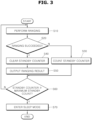
- FIG. 3 is a flowchart illustrating a control method of a UWB device according to an embodiment of the present disclosure.
- the processor 20 performs ranging together with a mobile device on the basis of a reception window set for UWB ranging in S10.
- the processor 20 determines whether or not the ranging has succeeded in S20.
- step S30 the processor 20 counts a standby counter in S30.
- step S20 the processor 20 clears the standby count in S40.
- the processor 20 outputs the result of the ranging in S50.
- the processor 20 compares a maximum standby count with the standby counter in S60.
- the maximum standby count is a reception standby time in which the ranging may fail even in the case in which a standby operation is performed by adjusting the reception window.
- the maximum standby count may be used to set a termination time at which the standby operation is terminated instead of being infinitely performed.
- the processor 20 exits the reception standby mode and enters a sleep mode in S70.
- step S60 When the standby counter is less than the maximum standby count as the result of the comparison of the maximum standby count with the standby counter in step S60, the processor returns to step S10 to perform the ranging.
- the UWB device when the anchor in the UWB device has successively failed the ranging, the UWB device enters the sleep mode by setting the maximum standby count corresponding to the reception window. In this manner, the UWB device may minimize unnecessary consumption of power that would otherwise be caused by infinite standby of a UWB signal that cannot be covered
- Implementations described in the present specification can be made by, for example, a method or a process, a device, a software program, a data stream, or a signal. Although the implementations are discussed only in the context of a single form (for example, discussed by the method only), the discussed features can also be implemented by another form (for example, a device or a program).
- the device can be implemented by suitable hardware, software, and firmware.
- the method can be implemented, for example, in a computer, a microprocessor, an integrated circuit, or a device such as a processor that generally refers to a processing device including a programmable logic device.
Landscapes
- Engineering & Computer Science (AREA)
- Computer Networks & Wireless Communication (AREA)
- Radar, Positioning & Navigation (AREA)
- Remote Sensing (AREA)
- Physics & Mathematics (AREA)
- General Physics & Mathematics (AREA)
- Signal Processing (AREA)
- Mobile Radio Communication Systems (AREA)
- Lock And Its Accessories (AREA)
Abstract
Description
- Exemplary embodiments of the present disclosure relate to an ultra-wideband (UWB) device and a control method thereof, and more particularly, to a UWB device and a control method thereof, wherein, when an anchor in the UWB device has successively failed a ranging procedure, the UWB device may enter a sleep mode by setting a maximum standby count corresponding to a UWB receiver window, thereby minimizing unnecessary power consumption caused by infinite standby of a UWB signal that cannot be covered.
- In general, a smart key (SMK) system locates a smart key (or a fob key), controls locking/unlocking of a vehicle door, and starts a vehicle using low frequency (LF, 125 kHz) or radio frequency (RF, 434MHz) technology.
- Some technologies, such as the global positioning system (GPS), Wi-Fi, and Bluetooth®, are used in order to provide local based services (LBSs), in which it is difficult to enable precise measurement. In contrast, ultra-wideband (UWB) has advantages such as a wide frequency band, low power communication, and high-precision positioning on a level of tens of centimeters.
- Here, the UWB is a technology for calculating the distance between communicating parties by multiplying a signal travel time between the communicating parties by the velocity of light using time of flight (ToF) technology.
- Conventional position tracking technologies based on the GPS and mobile communications networks have an error range of approximately 5 m to 50 m and 50 m to 200 m, respectively. With the GPS, a satellite signal may fail to reach a GPS receiver in a dense cluster of buildings in a city.
- Here, Wi-Fi technology may enable position tracking at low cost. However, with increases in the number of objects to be tracked, channel division may be limited, since the available frequency band is narrow. In addition, the connection of a mobile terminal to a stationary access point (AP) may be disconnected.
- Bluetooth® technology enables a plurality of sensors to be disposed at low cost. However, due to high communication latency, Bluetooth® technology is not suitable for real-time positioning tracking in a dynamic environment.
- In contrast, UWB technology uses a wide frequency band unlike Wi-Fi technology or Bluetooth® technology, and can transmit a large amount of information with low power and at a high transmission rate.
- Positioning using UWB technology has advantages, such as a low error range on a level of about 20 cm, high transmittance with respect to obstacles, and the ability to not be influenced by other signals, for example, Wi-Fi signals.
- Here, an operation of measuring the distance between a fob (or a fob key) and an anchor is referred to as ranging. In this case, a data structure is based on the IEEE802.15.4z standard, and about 200 µs is taken for the transmission of one packet. In addition, a slot is defined as an amount of time taken for the fob or the anchor to transmit a following signal (or receive a signal) after transmitting a signal once.
- A background technology of the present disclosure is disclosed in
Korean Patent Application Publication No. 10-2021-0137841 (published November 18, 2021 - When ranging is performed using UWB technology as described above, the anchor opens a receiver window before an expected reception time by RX_MARGIN_TIME (e.g., 10 ms) for standby of a signal allocated to each slot, and maintains the receiver window opened after the expected reception time by RX_TIMEOUT (e.g., 10 ms).
- The reason for which the receiver window is opened before and after the expected reception time is to overcome a time error that would otherwise be caused by the difference of the clock CLK between a smartphone and the anchor.
- For example, when the clock CLK of the smartphone performing the ranging once every 500 ms has a time error of +1000 ppm and the clock CLK of the anchor has a time error of -1000ppm, a clock difference of 2000 ppm (=1 ms) per 500 ms occurs. Thus, the time for which the ranging may be continued may vary depending on the length of the receiver window.
- In this case, when a set value is RX_MARGIN_TIME (e.g., 10 ms) + RX_TIMEOUT (e.g., 10 ms) = 20 ms, the ranging may be only continued 20 times every 500 ms.
- In this manner, when the RX_MARGIN_TIME/RX_TIMEOUT time of the receiver window is longer, the ranging may be continued for a longer time. In contrast, unnecessary consumption of power (or current) increases by the time during which the receiver window is opened, which may be problematic.
- In addition, according to physical characteristics of UWB communication, it is highly probable that an anchor opposite to a vehicle with respect to the smartphone may fail wireless communication due to the vehicle acting as an obstacle through metal components included therein.
- Thus, even in the case in which the anchor opposite to the vehicle is standing by for the ranging, when a reception signal is not continuously provided at actual estimated times, the time error between the smartphone and the anchor caused by the difference of the clock CLK accumulates. In this case, when the ranging succeeds at an estimated reception time, the time error occurring/accumulated due to the difference of the clock is reset with respect to the succeeded time. However, in the case that the ranging has successively failed, the time error is accumulated.
- When the ranging every 500 ms has failed 20 times, the ranging may not succeed even in the case that the smartphone has entered a radio communication available area. That is, while the anchor operates, substantially all ranging attempts fail, thereby consuming power needlessly.
- The present disclosure has been made in an effort to solve the above-described problems, and an objective of the present disclosure is directed to a UWB device and a control method thereof, wherein, when an anchor in the UWB device has successively failed a ranging procedure, the UWB device may enter a sleep mode by setting a maximum standby count corresponding to a UWB receiver window, thereby minimizing unnecessary power consumption caused by infinite standby of a UWB signal that cannot be covered.
- In an embodiment, provided is a UWB device including: a communications part configured to transmit and receive a packet to and from a mobile device; a memory in which a program for performing ranging and a maximum standby count are stored; and a processor configured to execute the program. The processor may perform the ranging together with the mobile device on basis of a set reception window, when the ranging fails, count a standby counter, and when the standby counter is equal to or greater than the maximum standby count, enter a sleep mode.
- When the ranging succeeds, the processor may clear the standby counter.
- The maximum standby count may be set according to the reception window.
- When the ranging succeeds, the processor may output a result of the ranging.
- The mobile device may include at least one of a fob key and a smart phone.
- Also provided is a control method of the UWB device, the control method including: performing, by a processor, ranging together with a mobile device on basis of a set reception window; when the ranging performed by the processor fails, counting, by the processor, a standby counter; when the ranging performed by the processor succeeds, clearing, by the processor, the standby counter; and comparing, by the processor, the standby counter with a maximum standby count, and repeating the ranging or entering a sleep mode.
- The maximum standby count may be set according to the reception window.
- The control method may further include outputting, by the processor, a result of the ranging when the ranging succeeds.
- In the repeating of the ranging or the entering of the sleep mode, the standby counter may be compared with the maximum standby count. When the standby counter is less than the maximum standby count, the processor may repeat the ranging. When the standby counter is equal to or greater than the maximum standby count, the processor may enter the sleep mode.
- In the UWB device and the control method thereof according to aspects of the present disclosure, when the anchor in the UWB device has successively failed a ranging procedure, the UWB device may enter a sleep mode by setting a maximum standby count corresponding to a UWB receiver window, thereby minimizing unnecessary power consumption caused by infinite standby of a UWB signal that cannot be covered.
-
-
FIG. 1 is a block diagram illustrating a configuration of a UWB device according to an embodiment of the present disclosure; -
FIG. 2 is a table illustrating the results of tests of times in which the UWB device according to an embodiment of the present disclosure may return when ranging fails depending on the receiver window; and -
FIG. 3 is a flowchart illustrating a control method of a UWB device according to an embodiment of the present disclosure. - Hereinafter, a UWB device and a control method thereof will be described below with reference to the accompanying drawings. In the specification and drawings, thicknesses of lines in the drawings and sizes of constituent elements may be exaggerated for clarity and convenience. Further, the following terms will be defined, considering functions thereof in the present disclosure, and may be varied according to intentions and customs of a user or an operator. Therefore, the terms should be defined on the basis of the contents of the entire specification.
-
FIG. 1 is a block diagram illustrating a configuration of a UWB device according to an embodiment of the present disclosure, andFIG. 2 is a table illustrating the results of tests of times in which the UWB device according to an embodiment of the present disclosure may return when ranging fails depending on the receiver window. - As illustrated in
FIG. 1 , the UWB device according to an embodiment of the present disclosure may include acommunications part 10, amemory 30, and aprocessor 20. - The
communications part 10 may transmit and receive a packet to and from amobile device 5 on the basis of UWB communication. Thecommunications part 1 may be implemented as a module, a device, a circuit, an antenna, or the like for UWB communication. The configuration of thecommunications part 10 may be realized using a technology well-known in the technical field to which the present disclosure pertains, and thus a further detailed description thereof will be omitted. - Here, the
mobile device 5 may include at least one of a fob key and a smartphone. - The
memory 30 may have a ranging program stored therein, and a maximum standby count set according to the reception window may be stored in thememory 30. - Here, the maximum standby count is a reception standby time in which ranging may fail even in the case in which a standby operation is performed by adjusting the reception window. The maximum standby count may be used to set a termination time at which the standby operation is terminated instead of being infinitely performed.
- For example,
FIG. 2 is a table illustrating actual test measurements of times in which the UWB device may return to a normal mode when the ranging has successively failed in a situation in which the reception windows RX_MARGIN_TIME/RX_TIMEOUT are 2ms/2ms, 5ms/5ms, and 10ms/10ms, respectively. Here, there may be variations in elements according to anchor samples as well as variations according to smartphone manufacturers/samples. - As illustrated in
FIG. 2 , when the reception window is 2ms/2ms, it can be appreciated that, when returning to the normal mode has failed through repetition of about 1 minute, the ranging will fail successively even in the case the standby operation is performed for 10 minutes. In addition, when the reception window is 10ms/10ms, it can be appreciated that, when returning to the normal mode has failed through repetition of about 5 minutes, the ranging will fail successively. - Thus, when the reception window is 10ms/10ms, the maximum standby count may be set to be 5 minutes or 1,000 times.
- For example, when the ranging is performed once every about 300 ms, the ranging may be performed 1,000 for 300,000 ms (=300 seconds=5 minutes). Therefore, when the ranging has failed successively for 1,000 times, it is meaningless to maintain the reception standby mode for the ranging in current reception window conditions (RX_MARGIN_TIME/RX_TIMEOUT=10 ms/10 ms), since the ranging fails due to the distorted window.
- Thus, the ranging reception standby time may be set in reception window conditions and maximum standby count conditions, thereby minimizing needless consumption of power.
- The
processor 20 may execute the program stored in thememory 30. - That is, the
processor 20 may perform the ranging together with themobile device 5 on the basis of the reception window. Here, performing the ranging is a technology well-known in the technical field to which the present disclosure pertains, and thus a further detailed description thereof will be omitted. - When the ranging fails, the
processor 2 counts a standby counter. Here, when the ranging succeeds at least once, the standby counter is cleared and the result of the ranging is output. - In this manner, the
processor 20 counts the standby counter while performing the ranging. When the ranging fails and the standby counter is equal to or greater than the maximum standby count, theprocessor 20 may exit the reception standby mode for the ranging and enter a sleep mode. - As described above, in the UWB device according to an embodiment of the present disclosure, when the anchor in the UWB device has successively failed the ranging, the UWB device enters the sleep mode by setting the maximum standby count corresponding to the reception window. In this manner, the UWB device may minimize unnecessary consumption of power that would otherwise be caused by infinite standby of a UWB signal that cannot be covered.
-
FIG. 3 is a flowchart illustrating a control method of a UWB device according to an embodiment of the present disclosure. - As illustrated in
FIG. 3 , in the control method of a UWB device according to an embodiment of the present disclosure, first, theprocessor 20 performs ranging together with a mobile device on the basis of a reception window set for UWB ranging in S10. - After the ranging is performed in step S10, the
processor 20 determines whether or not the ranging has succeeded in S20. - When the ranging fails instead of succeeding in step S20, the
processor 20 counts a standby counter in S30. - In contrast, when the ranging succeeds in step S20, the
processor 20 clears the standby count in S40. - In addition, the
processor 20 outputs the result of the ranging in S50. - After the standby counter is counted in step S30 in response to the failure of the ranging in step S30 or when the result of the ranging is output in response to the success of the ranging in step S20, the
processor 20 compares a maximum standby count with the standby counter in S60. - Here, the maximum standby count is a reception standby time in which the ranging may fail even in the case in which a standby operation is performed by adjusting the reception window. The maximum standby count may be used to set a termination time at which the standby operation is terminated instead of being infinitely performed.
- When the standby counter is equal to or greater than the maximum standby count as the result of the comparison of the maximum standby count with the standby counter in step S60, the
processor 20 exits the reception standby mode and enters a sleep mode in S70. - When the standby counter is less than the maximum standby count as the result of the comparison of the maximum standby count with the standby counter in step S60, the processor returns to step S10 to perform the ranging.
- In the control method of a UWB device according to an embodiment of the present disclosure as described above, when the anchor in the UWB device has successively failed the ranging, the UWB device enters the sleep mode by setting the maximum standby count corresponding to the reception window. In this manner, the UWB device may minimize unnecessary consumption of power that would otherwise be caused by infinite standby of a UWB signal that cannot be covered
- Implementations described in the present specification can be made by, for example, a method or a process, a device, a software program, a data stream, or a signal. Although the implementations are discussed only in the context of a single form (for example, discussed by the method only), the discussed features can also be implemented by another form (for example, a device or a program). The device can be implemented by suitable hardware, software, and firmware. The method can be implemented, for example, in a computer, a microprocessor, an integrated circuit, or a device such as a processor that generally refers to a processing device including a programmable logic device.
Claims (9)
- A ultra-wideband, UWB, device comprising:a communications part configured to transmit and receive a packet to and from a mobile device;a memory in which a program for performing ranging and a maximum standby count are stored; anda processor configured to execute the program,wherein the processor performs the ranging together with the mobile device on basis of a set reception window, when the ranging fails, counts a standby counter, and when the standby counter is equal to or greater than the maximum standby count, enters a sleep mode.
- The UWB device of claim 1, wherein, when the ranging succeeds, the processor clears the standby counter.
- The UWB device of any of the preceding claims, wherein, when the ranging succeeds, the processor outputs a result of the ranging.
- The UWB device of any of the preceding claims, wherein the maximum standby count is set according to the reception window.
- The UWB device of any of the preceding claims, wherein the mobile device comprises at least one of a fob key and a smart phone.
- A control method of the ultra-wideband, UWB, device, the control method comprising:performing, by a processor, ranging together with a mobile device on basis of a set reception window;when the ranging performed by the processor fails, counting, by the processor, a standby counter;when the ranging performed by the processor succeeds, clearing, by the processor, the standby counter; andcomparing, by the processor, the standby counter with a maximum standby count, and repeating the ranging or entering a sleep mode.
- The control method of claim 6, wherein the maximum standby count is set according to the reception window.
- The control method of claim 6 or 7, further comprising outputting, by the processor, a result of the ranging when the ranging succeeds.
- The control method any of claims 6 to 8, wherein, in the repeating of the ranging or the entering of the sleep mode,the standby counter is compared with the maximum standby count, andwhen the standby counter is less than the maximum standby count, the processor repeats the ranging, andwhen the standby counter is equal to or greater than the maximum standby count, the processor enters the sleep mode.
Applications Claiming Priority (1)
| Application Number | Priority Date | Filing Date | Title |
|---|---|---|---|
| KR1020210188614A KR20230099335A (en) | 2021-12-27 | 2021-12-27 | Ultra wide band apparatus and control method thereof |
Publications (2)
| Publication Number | Publication Date |
|---|---|
| EP4202487A1 true EP4202487A1 (en) | 2023-06-28 |
| EP4202487B1 EP4202487B1 (en) | 2025-09-03 |
Family
ID=84887686
Family Applications (1)
| Application Number | Title | Priority Date | Filing Date |
|---|---|---|---|
| EP22215848.7A Active EP4202487B1 (en) | 2021-12-27 | 2022-12-22 | Uwb device and control method thereof |
Country Status (4)
| Country | Link |
|---|---|
| US (1) | US12183137B2 (en) |
| EP (1) | EP4202487B1 (en) |
| KR (1) | KR20230099335A (en) |
| CN (1) | CN116367280A (en) |
Families Citing this family (1)
| Publication number | Priority date | Publication date | Assignee | Title |
|---|---|---|---|---|
| KR20230099335A (en) * | 2021-12-27 | 2023-07-04 | 현대모비스 주식회사 | Ultra wide band apparatus and control method thereof |
Citations (3)
| Publication number | Priority date | Publication date | Assignee | Title |
|---|---|---|---|---|
| US20200137676A1 (en) * | 2018-10-26 | 2020-04-30 | Samsung Electronics Co., Ltd. | Method and device for performing scheduling by using alternative signals in wireless communication system |
| US20200366335A1 (en) * | 2019-05-14 | 2020-11-19 | Samsung Electronics Co., Ltd. | Electronic device performing ranging operation by using ultra wide-band and operation method of the electronic device |
| KR20210137841A (en) | 2020-05-11 | 2021-11-18 | 현대모비스 주식회사 | Uwb system |
Family Cites Families (11)
| Publication number | Priority date | Publication date | Assignee | Title |
|---|---|---|---|---|
| US9001703B2 (en) * | 2012-11-12 | 2015-04-07 | Motorola Solutions, Inc. | Scalable broadband group call via unicast downlink traffic consolidation and local re-broadcast |
| US8874182B2 (en) * | 2013-01-15 | 2014-10-28 | Google Inc. | Encapsulated electronics |
| JP6480706B2 (en) * | 2014-11-04 | 2019-03-13 | キヤノン株式会社 | Image forming apparatus, control method therefor, and program |
| US11281955B2 (en) * | 2017-12-01 | 2022-03-22 | Metrc Llc | System and method for programming wireless sensor tags in food service operations |
| US10793144B2 (en) * | 2018-04-09 | 2020-10-06 | Ford Global Technologies, Llc | Vehicle remote park-assist communication counters |
| US11397239B2 (en) * | 2018-10-24 | 2022-07-26 | Infineon Technologies Ag | Radar sensor FSM low power mode |
| US11289946B2 (en) * | 2019-04-08 | 2022-03-29 | Purdue Research Foundation | Method and system of uniform wireless power distribution within a chamber |
| KR102407317B1 (en) * | 2019-07-12 | 2022-06-13 | 콘티넨탈 오토모티브 코리아(주) | System for controlling a vehicle and operating method thereof |
| KR20230028034A (en) | 2021-08-20 | 2023-02-28 | 현대모비스 주식회사 | Uwb on/off operation method to minimize power consumption and uwb anchor using the same |
| KR20230034059A (en) | 2021-09-02 | 2023-03-09 | 현대모비스 주식회사 | Uwb on/off operation method to minimize degradation of positioning performance and uwb anchor using the same |
| KR20230099335A (en) * | 2021-12-27 | 2023-07-04 | 현대모비스 주식회사 | Ultra wide band apparatus and control method thereof |
-
2021
- 2021-12-27 KR KR1020210188614A patent/KR20230099335A/en active Pending
-
2022
- 2022-12-21 US US18/086,020 patent/US12183137B2/en active Active
- 2022-12-21 CN CN202211660265.5A patent/CN116367280A/en active Pending
- 2022-12-22 EP EP22215848.7A patent/EP4202487B1/en active Active
Patent Citations (3)
| Publication number | Priority date | Publication date | Assignee | Title |
|---|---|---|---|---|
| US20200137676A1 (en) * | 2018-10-26 | 2020-04-30 | Samsung Electronics Co., Ltd. | Method and device for performing scheduling by using alternative signals in wireless communication system |
| US20200366335A1 (en) * | 2019-05-14 | 2020-11-19 | Samsung Electronics Co., Ltd. | Electronic device performing ranging operation by using ultra wide-band and operation method of the electronic device |
| KR20210137841A (en) | 2020-05-11 | 2021-11-18 | 현대모비스 주식회사 | Uwb system |
Also Published As
| Publication number | Publication date |
|---|---|
| KR20230099335A (en) | 2023-07-04 |
| US12183137B2 (en) | 2024-12-31 |
| CN116367280A (en) | 2023-06-30 |
| US20230206705A1 (en) | 2023-06-29 |
| EP4202487B1 (en) | 2025-09-03 |
Similar Documents
| Publication | Publication Date | Title |
|---|---|---|
| US12339386B2 (en) | UWB ranging control device and UWB ranging method using the same | |
| EP3849093B1 (en) | Ultra-wideband device power optimization | |
| US8184038B2 (en) | Two-way ranging with inter-pulse transmission and reception | |
| US11740342B2 (en) | Method and apparatus for selecting a ranging anchor based on characteristics of communication between a connection anchor and a mobile electronic device | |
| US11418231B2 (en) | UWB system | |
| EP4080781B1 (en) | Communication device and operating method | |
| CN114827887A (en) | Timing synchronization digital key positioning system based on Bluetooth AoA positioning and ranging | |
| US20230039434A1 (en) | Communication device and position identification method | |
| Sun et al. | Partial symbol recovery for interference resilience in low-power wide area networks | |
| US20250110232A1 (en) | Time-of-flight measurement system and method | |
| US20230063790A1 (en) | Uwb on/off operation method to minimize degradation of ranging performance and uwb anchor using the same | |
| EP4202487B1 (en) | Uwb device and control method thereof | |
| EP2179506B1 (en) | Correlation-driven adaptation of frequency control for a rf receiver device | |
| EP4092638B1 (en) | Vehicle access system and method of accessing a vehicle | |
| KR20210137841A (en) | Uwb system | |
| US20210120496A1 (en) | Time slotted scan receiver | |
| KR102822762B1 (en) | Uwb system | |
| US20230333240A1 (en) | Apparatus and method for setting a uwb ranging period | |
| CN1954233B (en) | A GPS device | |
| WO2003076964A1 (en) | System and method for speed indication through transmit power control commands | |
| US12363662B2 (en) | Frame synchronization detection with fractional approximation | |
| CN109451531B (en) | System and method for measuring field intensity in LTE cell range | |
| US12574269B2 (en) | Puncturing a correlation sequence used in high accuracy distance measurements | |
| US12537616B2 (en) | Frame synchronization detection with an adaptive threshold | |
| US11811578B1 (en) | Frame synchronization detection with frequency estimation |
Legal Events
| Date | Code | Title | Description |
|---|---|---|---|
| PUAI | Public reference made under article 153(3) epc to a published international application that has entered the european phase |
Free format text: ORIGINAL CODE: 0009012 |
|
| STAA | Information on the status of an ep patent application or granted ep patent |
Free format text: STATUS: THE APPLICATION HAS BEEN PUBLISHED |
|
| AK | Designated contracting states |
Kind code of ref document: A1 Designated state(s): AL AT BE BG CH CY CZ DE DK EE ES FI FR GB GR HR HU IE IS IT LI LT LU LV MC ME MK MT NL NO PL PT RO RS SE SI SK SM TR |
|
| STAA | Information on the status of an ep patent application or granted ep patent |
Free format text: STATUS: REQUEST FOR EXAMINATION WAS MADE |
|
| 17P | Request for examination filed |
Effective date: 20231017 |
|
| RBV | Designated contracting states (corrected) |
Designated state(s): AL AT BE BG CH CY CZ DE DK EE ES FI FR GB GR HR HU IE IS IT LI LT LU LV MC ME MK MT NL NO PL PT RO RS SE SI SK SM TR |
|
| STAA | Information on the status of an ep patent application or granted ep patent |
Free format text: STATUS: EXAMINATION IS IN PROGRESS |
|
| 17Q | First examination report despatched |
Effective date: 20231212 |
|
| GRAP | Despatch of communication of intention to grant a patent |
Free format text: ORIGINAL CODE: EPIDOSNIGR1 |
|
| STAA | Information on the status of an ep patent application or granted ep patent |
Free format text: STATUS: GRANT OF PATENT IS INTENDED |
|
| RIC1 | Information provided on ipc code assigned before grant |
Ipc: G07C 9/00 20200101ALN20250305BHEP Ipc: G01S 13/76 20060101ALN20250305BHEP Ipc: G01S 5/02 20100101ALN20250305BHEP Ipc: G01S 5/00 20060101ALN20250305BHEP Ipc: G01S 11/02 20100101AFI20250305BHEP |
|
| INTG | Intention to grant announced |
Effective date: 20250326 |
|
| GRAS | Grant fee paid |
Free format text: ORIGINAL CODE: EPIDOSNIGR3 |
|
| GRAA | (expected) grant |
Free format text: ORIGINAL CODE: 0009210 |
|
| STAA | Information on the status of an ep patent application or granted ep patent |
Free format text: STATUS: THE PATENT HAS BEEN GRANTED |
|
| AK | Designated contracting states |
Kind code of ref document: B1 Designated state(s): AL AT BE BG CH CY CZ DE DK EE ES FI FR GB GR HR HU IE IS IT LI LT LU LV MC ME MK MT NL NO PL PT RO RS SE SI SK SM TR |
|
| P01 | Opt-out of the competence of the unified patent court (upc) registered |
Free format text: CASE NUMBER: UPC_APP_1002_4202487/2025 Effective date: 20250724 |
|
| RAP3 | Party data changed (applicant data changed or rights of an application transferred) |
Owner name: HYUNDAI MOBIS CO., LTD. |
|
| REG | Reference to a national code |
Ref country code: CH Ref legal event code: EP |
|
| REG | Reference to a national code |
Ref country code: DE Ref legal event code: R096 Ref document number: 602022020679 Country of ref document: DE |
|
| REG | Reference to a national code |
Ref country code: IE Ref legal event code: FG4D |
|
| REG | Reference to a national code |
Ref country code: NL Ref legal event code: MP Effective date: 20250903 |
|
| PGFP | Annual fee paid to national office [announced via postgrant information from national office to epo] |
Ref country code: DE Payment date: 20251120 Year of fee payment: 4 |
|
| PG25 | Lapsed in a contracting state [announced via postgrant information from national office to epo] |
Ref country code: NO Free format text: LAPSE BECAUSE OF FAILURE TO SUBMIT A TRANSLATION OF THE DESCRIPTION OR TO PAY THE FEE WITHIN THE PRESCRIBED TIME-LIMIT Effective date: 20251203 |
|
| REG | Reference to a national code |
Ref country code: LT Ref legal event code: MG9D |
|
| PG25 | Lapsed in a contracting state [announced via postgrant information from national office to epo] |
Ref country code: FI Free format text: LAPSE BECAUSE OF FAILURE TO SUBMIT A TRANSLATION OF THE DESCRIPTION OR TO PAY THE FEE WITHIN THE PRESCRIBED TIME-LIMIT Effective date: 20250903 |
|
| PG25 | Lapsed in a contracting state [announced via postgrant information from national office to epo] |
Ref country code: HR Free format text: LAPSE BECAUSE OF FAILURE TO SUBMIT A TRANSLATION OF THE DESCRIPTION OR TO PAY THE FEE WITHIN THE PRESCRIBED TIME-LIMIT Effective date: 20250903 |
|
| PGFP | Annual fee paid to national office [announced via postgrant information from national office to epo] |
Ref country code: FR Payment date: 20251125 Year of fee payment: 4 |
|
| PG25 | Lapsed in a contracting state [announced via postgrant information from national office to epo] |
Ref country code: GR Free format text: LAPSE BECAUSE OF FAILURE TO SUBMIT A TRANSLATION OF THE DESCRIPTION OR TO PAY THE FEE WITHIN THE PRESCRIBED TIME-LIMIT Effective date: 20251204 |
|
| PG25 | Lapsed in a contracting state [announced via postgrant information from national office to epo] |
Ref country code: SE Free format text: LAPSE BECAUSE OF FAILURE TO SUBMIT A TRANSLATION OF THE DESCRIPTION OR TO PAY THE FEE WITHIN THE PRESCRIBED TIME-LIMIT Effective date: 20250903 |
|
| PG25 | Lapsed in a contracting state [announced via postgrant information from national office to epo] |
Ref country code: LV Free format text: LAPSE BECAUSE OF FAILURE TO SUBMIT A TRANSLATION OF THE DESCRIPTION OR TO PAY THE FEE WITHIN THE PRESCRIBED TIME-LIMIT Effective date: 20250903 |
|
| PG25 | Lapsed in a contracting state [announced via postgrant information from national office to epo] |
Ref country code: PL Free format text: LAPSE BECAUSE OF FAILURE TO SUBMIT A TRANSLATION OF THE DESCRIPTION OR TO PAY THE FEE WITHIN THE PRESCRIBED TIME-LIMIT Effective date: 20250903 Ref country code: BG Free format text: LAPSE BECAUSE OF FAILURE TO SUBMIT A TRANSLATION OF THE DESCRIPTION OR TO PAY THE FEE WITHIN THE PRESCRIBED TIME-LIMIT Effective date: 20250903 |
|
| PG25 | Lapsed in a contracting state [announced via postgrant information from national office to epo] |
Ref country code: RS Free format text: LAPSE BECAUSE OF FAILURE TO SUBMIT A TRANSLATION OF THE DESCRIPTION OR TO PAY THE FEE WITHIN THE PRESCRIBED TIME-LIMIT Effective date: 20251203 |
|
| PG25 | Lapsed in a contracting state [announced via postgrant information from national office to epo] |
Ref country code: ES Free format text: LAPSE BECAUSE OF FAILURE TO SUBMIT A TRANSLATION OF THE DESCRIPTION OR TO PAY THE FEE WITHIN THE PRESCRIBED TIME-LIMIT Effective date: 20250903 |
|
| REG | Reference to a national code |
Ref country code: AT Ref legal event code: MK05 Ref document number: 1833671 Country of ref document: AT Kind code of ref document: T Effective date: 20250903 |
|
| PG25 | Lapsed in a contracting state [announced via postgrant information from national office to epo] |
Ref country code: NL Free format text: LAPSE BECAUSE OF FAILURE TO SUBMIT A TRANSLATION OF THE DESCRIPTION OR TO PAY THE FEE WITHIN THE PRESCRIBED TIME-LIMIT Effective date: 20250903 |
|
| PG25 | Lapsed in a contracting state [announced via postgrant information from national office to epo] |
Ref country code: SM Free format text: LAPSE BECAUSE OF FAILURE TO SUBMIT A TRANSLATION OF THE DESCRIPTION OR TO PAY THE FEE WITHIN THE PRESCRIBED TIME-LIMIT Effective date: 20250903 |
|
| PG25 | Lapsed in a contracting state [announced via postgrant information from national office to epo] |
Ref country code: AT Free format text: LAPSE BECAUSE OF FAILURE TO SUBMIT A TRANSLATION OF THE DESCRIPTION OR TO PAY THE FEE WITHIN THE PRESCRIBED TIME-LIMIT Effective date: 20250903 |
|
| PG25 | Lapsed in a contracting state [announced via postgrant information from national office to epo] |
Ref country code: RO Free format text: LAPSE BECAUSE OF FAILURE TO SUBMIT A TRANSLATION OF THE DESCRIPTION OR TO PAY THE FEE WITHIN THE PRESCRIBED TIME-LIMIT Effective date: 20250903 Ref country code: IT Free format text: LAPSE BECAUSE OF FAILURE TO SUBMIT A TRANSLATION OF THE DESCRIPTION OR TO PAY THE FEE WITHIN THE PRESCRIBED TIME-LIMIT Effective date: 20250903 |
|
| PG25 | Lapsed in a contracting state [announced via postgrant information from national office to epo] |
Ref country code: IS Free format text: LAPSE BECAUSE OF FAILURE TO SUBMIT A TRANSLATION OF THE DESCRIPTION OR TO PAY THE FEE WITHIN THE PRESCRIBED TIME-LIMIT Effective date: 20260103 |
|
| PG25 | Lapsed in a contracting state [announced via postgrant information from national office to epo] |
Ref country code: CZ Free format text: LAPSE BECAUSE OF FAILURE TO SUBMIT A TRANSLATION OF THE DESCRIPTION OR TO PAY THE FEE WITHIN THE PRESCRIBED TIME-LIMIT Effective date: 20250903 Ref country code: PT Free format text: LAPSE BECAUSE OF FAILURE TO SUBMIT A TRANSLATION OF THE DESCRIPTION OR TO PAY THE FEE WITHIN THE PRESCRIBED TIME-LIMIT Effective date: 20260105 |
|
| PG25 | Lapsed in a contracting state [announced via postgrant information from national office to epo] |
Ref country code: EE Free format text: LAPSE BECAUSE OF FAILURE TO SUBMIT A TRANSLATION OF THE DESCRIPTION OR TO PAY THE FEE WITHIN THE PRESCRIBED TIME-LIMIT Effective date: 20250903 Ref country code: SK Free format text: LAPSE BECAUSE OF FAILURE TO SUBMIT A TRANSLATION OF THE DESCRIPTION OR TO PAY THE FEE WITHIN THE PRESCRIBED TIME-LIMIT Effective date: 20250903 |
|
| REG | Reference to a national code |
Ref country code: DE Ref legal event code: R097 Ref document number: 602022020679 Country of ref document: DE |
|
| PG25 | Lapsed in a contracting state [announced via postgrant information from national office to epo] |
Ref country code: LT Free format text: LAPSE BECAUSE OF FAILURE TO SUBMIT A TRANSLATION OF THE DESCRIPTION OR TO PAY THE FEE WITHIN THE PRESCRIBED TIME-LIMIT Effective date: 20250903 |
|
| PG25 | Lapsed in a contracting state [announced via postgrant information from national office to epo] |
Ref country code: MC Free format text: LAPSE BECAUSE OF FAILURE TO SUBMIT A TRANSLATION OF THE DESCRIPTION OR TO PAY THE FEE WITHIN THE PRESCRIBED TIME-LIMIT Effective date: 20250903 |
|
| PG25 | Lapsed in a contracting state [announced via postgrant information from national office to epo] |
Ref country code: DK Free format text: LAPSE BECAUSE OF FAILURE TO SUBMIT A TRANSLATION OF THE DESCRIPTION OR TO PAY THE FEE WITHIN THE PRESCRIBED TIME-LIMIT Effective date: 20250903 |
|
| PLBE | No opposition filed within time limit |
Free format text: ORIGINAL CODE: 0009261 |
|
| STAA | Information on the status of an ep patent application or granted ep patent |
Free format text: STATUS: NO OPPOSITION FILED WITHIN TIME LIMIT |
|
| REG | Reference to a national code |
Ref country code: CH Ref legal event code: L10 Free format text: ST27 STATUS EVENT CODE: U-0-0-L10-L00 (AS PROVIDED BY THE NATIONAL OFFICE) Effective date: 20260715 |
|
| REG | Reference to a national code |
Ref country code: CH Ref legal event code: H13 Free format text: ST27 STATUS EVENT CODE: U-0-0-H10-H13 (AS PROVIDED BY THE NATIONAL OFFICE) Effective date: 20260723 |
|
| 26N | No opposition filed |
Effective date: 20260604 |