EP4202457A1 - Battery diagnosis device and method - Google Patents
Battery diagnosis device and method Download PDFInfo
- Publication number
- EP4202457A1 EP4202457A1 EP21915796.3A EP21915796A EP4202457A1 EP 4202457 A1 EP4202457 A1 EP 4202457A1 EP 21915796 A EP21915796 A EP 21915796A EP 4202457 A1 EP4202457 A1 EP 4202457A1
- Authority
- EP
- European Patent Office
- Prior art keywords
- change rate
- voltage
- battery
- control unit
- voltage change
- Prior art date
- Legal status (The legal status is an assumption and is not a legal conclusion. Google has not performed a legal analysis and makes no representation as to the accuracy of the status listed.)
- Pending
Links
Images


Classifications
-
- G—PHYSICS
- G01—MEASURING; TESTING
- G01R—MEASURING ELECTRIC VARIABLES; MEASURING MAGNETIC VARIABLES
- G01R31/00—Arrangements for testing electric properties; Arrangements for locating electric faults; Arrangements for electrical testing characterised by what is being tested not provided for elsewhere
- G01R31/36—Arrangements for testing, measuring or monitoring the electrical condition of accumulators or electric batteries, e.g. capacity or state of charge [SoC]
- G01R31/392—Determining battery ageing or deterioration, e.g. state of health
-
- G—PHYSICS
- G01—MEASURING; TESTING
- G01R—MEASURING ELECTRIC VARIABLES; MEASURING MAGNETIC VARIABLES
- G01R31/00—Arrangements for testing electric properties; Arrangements for locating electric faults; Arrangements for electrical testing characterised by what is being tested not provided for elsewhere
- G01R31/36—Arrangements for testing, measuring or monitoring the electrical condition of accumulators or electric batteries, e.g. capacity or state of charge [SoC]
- G01R31/3644—Constructional arrangements
- G01R31/3648—Constructional arrangements comprising digital calculation means, e.g. for performing an algorithm
-
- G—PHYSICS
- G01—MEASURING; TESTING
- G01R—MEASURING ELECTRIC VARIABLES; MEASURING MAGNETIC VARIABLES
- G01R19/00—Arrangements for measuring currents or voltages or for indicating presence or sign thereof
- G01R19/0038—Circuits for comparing several input signals and for indicating the result of this comparison, e.g. equal, different, greater, smaller (comparing pulses or pulse trains according to amplitude)
-
- G—PHYSICS
- G01—MEASURING; TESTING
- G01R—MEASURING ELECTRIC VARIABLES; MEASURING MAGNETIC VARIABLES
- G01R19/00—Arrangements for measuring currents or voltages or for indicating presence or sign thereof
- G01R19/12—Measuring rate of change
-
- G—PHYSICS
- G01—MEASURING; TESTING
- G01R—MEASURING ELECTRIC VARIABLES; MEASURING MAGNETIC VARIABLES
- G01R19/00—Arrangements for measuring currents or voltages or for indicating presence or sign thereof
- G01R19/165—Indicating that current or voltage is either above or below a predetermined value or within or outside a predetermined range of values
- G01R19/16533—Indicating that current or voltage is either above or below a predetermined value or within or outside a predetermined range of values characterised by the application
- G01R19/16538—Indicating that current or voltage is either above or below a predetermined value or within or outside a predetermined range of values characterised by the application in AC or DC supplies
- G01R19/16542—Indicating that current or voltage is either above or below a predetermined value or within or outside a predetermined range of values characterised by the application in AC or DC supplies for batteries
-
- G—PHYSICS
- G01—MEASURING; TESTING
- G01R—MEASURING ELECTRIC VARIABLES; MEASURING MAGNETIC VARIABLES
- G01R19/00—Arrangements for measuring currents or voltages or for indicating presence or sign thereof
- G01R19/165—Indicating that current or voltage is either above or below a predetermined value or within or outside a predetermined range of values
- G01R19/16566—Circuits and arrangements for comparing voltage or current with one or several thresholds and for indicating the result not covered by subgroups G01R19/16504, G01R19/16528, G01R19/16533
-
- G—PHYSICS
- G01—MEASURING; TESTING
- G01R—MEASURING ELECTRIC VARIABLES; MEASURING MAGNETIC VARIABLES
- G01R31/00—Arrangements for testing electric properties; Arrangements for locating electric faults; Arrangements for electrical testing characterised by what is being tested not provided for elsewhere
- G01R31/36—Arrangements for testing, measuring or monitoring the electrical condition of accumulators or electric batteries, e.g. capacity or state of charge [SoC]
- G01R31/382—Arrangements for monitoring battery or accumulator variables, e.g. SoC
- G01R31/3835—Arrangements for monitoring battery or accumulator variables, e.g. SoC involving only voltage measurements
-
- G—PHYSICS
- G01—MEASURING; TESTING
- G01R—MEASURING ELECTRIC VARIABLES; MEASURING MAGNETIC VARIABLES
- G01R31/00—Arrangements for testing electric properties; Arrangements for locating electric faults; Arrangements for electrical testing characterised by what is being tested not provided for elsewhere
- G01R31/36—Arrangements for testing, measuring or monitoring the electrical condition of accumulators or electric batteries, e.g. capacity or state of charge [SoC]
- G01R31/396—Acquisition or processing of data for testing or for monitoring individual cells or groups of cells within a battery
-
- H—ELECTRICITY
- H01—ELECTRIC ELEMENTS
- H01M—PROCESSES OR MEANS, e.g. BATTERIES, FOR THE DIRECT CONVERSION OF CHEMICAL ENERGY INTO ELECTRICAL ENERGY
- H01M10/00—Secondary cells; Manufacture thereof
- H01M10/42—Methods or arrangements for servicing or maintenance of secondary cells or secondary half-cells
-
- H—ELECTRICITY
- H01—ELECTRIC ELEMENTS
- H01M—PROCESSES OR MEANS, e.g. BATTERIES, FOR THE DIRECT CONVERSION OF CHEMICAL ENERGY INTO ELECTRICAL ENERGY
- H01M10/00—Secondary cells; Manufacture thereof
- H01M10/42—Methods or arrangements for servicing or maintenance of secondary cells or secondary half-cells
- H01M10/48—Accumulators combined with arrangements for measuring, testing or indicating the condition of cells, e.g. the level or density of the electrolyte
-
- H—ELECTRICITY
- H01—ELECTRIC ELEMENTS
- H01M—PROCESSES OR MEANS, e.g. BATTERIES, FOR THE DIRECT CONVERSION OF CHEMICAL ENERGY INTO ELECTRICAL ENERGY
- H01M10/00—Secondary cells; Manufacture thereof
- H01M10/42—Methods or arrangements for servicing or maintenance of secondary cells or secondary half-cells
- H01M10/48—Accumulators combined with arrangements for measuring, testing or indicating the condition of cells, e.g. the level or density of the electrolyte
- H01M10/482—Accumulators combined with arrangements for measuring, testing or indicating the condition of cells, e.g. the level or density of the electrolyte for several batteries or cells simultaneously or sequentially
-
- H—ELECTRICITY
- H01—ELECTRIC ELEMENTS
- H01M—PROCESSES OR MEANS, e.g. BATTERIES, FOR THE DIRECT CONVERSION OF CHEMICAL ENERGY INTO ELECTRICAL ENERGY
- H01M10/00—Secondary cells; Manufacture thereof
- H01M10/42—Methods or arrangements for servicing or maintenance of secondary cells or secondary half-cells
- H01M10/425—Structural combination with electronic components, e.g. electronic circuits integrated to the outside of the casing
- H01M2010/4271—Battery management systems including electronic circuits, e.g. control of current or voltage to keep battery in healthy state, cell balancing
-
- Y—GENERAL TAGGING OF NEW TECHNOLOGICAL DEVELOPMENTS; GENERAL TAGGING OF CROSS-SECTIONAL TECHNOLOGIES SPANNING OVER SEVERAL SECTIONS OF THE IPC; TECHNICAL SUBJECTS COVERED BY FORMER USPC CROSS-REFERENCE ART COLLECTIONS [XRACs] AND DIGESTS
- Y02—TECHNOLOGIES OR APPLICATIONS FOR MITIGATION OR ADAPTATION AGAINST CLIMATE CHANGE
- Y02E—REDUCTION OF GREENHOUSE GAS [GHG] EMISSIONS, RELATED TO ENERGY GENERATION, TRANSMISSION OR DISTRIBUTION
- Y02E60/00—Enabling technologies; Technologies with a potential or indirect contribution to GHG emissions mitigation
- Y02E60/10—Energy storage using batteries
Definitions
- the present disclosure relates to a battery diagnosing apparatus and method, and more particularly, to a battery diagnosing apparatus and method capable of diagnosing a state of a battery module based on voltage behavior of a plurality of battery cells included in the battery module.
- Batteries commercially available at present include nickel-cadmium batteries, nickel hydrogen batteries, nickel-zinc batteries, lithium batteries and the like.
- the lithium batteries are in the limelight since they have almost no memory effect compared to nickel-based batteries and also have very low self-charging rate and high energy density.
- the state of the battery is diagnosed in consideration of voltage, temperature and current change amounts of the battery.
- the present disclosure is designed to solve the problems of the related art, and therefore the present disclosure is directed to providing a battery diagnosing apparatus and method capable of diagnosing a state of a battery module based on voltage fluctuation trends of a plurality of battery cells.
- a battery diagnosing apparatus may comprise: a voltage measuring unit configured to measure a voltage of each of a plurality of battery cells included in a battery module at every voltage measurement cycle; and a control unit configured to obtain a voltage value for the plurality of battery cells from the voltage measuring unit at every voltage measurement cycle, calculate a voltage change amount between the plurality of obtained voltage values for the plurality of battery cells, calculate a voltage change rate between the plurality of calculated voltage change amounts at every diagnosis cycle different from the voltage measurement cycle, and diagnose the battery module based on one or more voltage change rates calculated up to a current diagnosis cycle and a preset criterion change rate.
- the control unit may be configured to compare magnitudes of the voltage change rate calculated at the current diagnosis cycle and the criterion change rate, and diagnose a state of the battery module based on the comparison result.
- the control unit may be configured to diagnose the battery module based on a reference change rate preset at a previous diagnosis cycle and the voltage change rate, when the voltage change rate is equal to or greater than the criterion change rate.
- the control unit may be configured to diagnose the battery module as a normal module, when the voltage change rate is less than the criterion change rate.
- the control unit may be configured to preset a largest voltage change rate among one or more voltage change rates calculated at the previous diagnosis cycle as the reference change rate.
- the control unit may be configured to diagnose the battery module as a defective module, when the voltage change rate is equal to or greater than the criterion change rate and the reference change rate.
- the control unit may be configured to diagnose the battery module as the normal module, when the voltage change rate is equal to or greater than the criterion change rate and less than the reference change rate.
- the control unit may be configured to determine a state of the battery module based on at least one of the voltage change rate, the criterion change rate and the reference change rate at every diagnosis cycle, adjust a preset counting value according to the determined state of the battery module, and diagnose the battery module based on the adjusted counting value and a preset criterion value.
- the control unit may be configured to diagnose the battery module as the defective module, when the adjusted counting value is equal to or greater than the criterion value.
- the control unit may be configured to decrease the counting value, when the voltage change rate is less than the criterion change rate.
- the control unit may be configured to decrease the counting value, when the voltage change rate is equal to or greater than the criterion change rate and less than the reference change rate.
- the control unit may be configured to increase the counting value, when the voltage change rate is equal to or greater than the criterion change rate and the reference change rate.
- the diagnosis cycle may be set to be greater than the voltage measurement cycle.
- a battery pack according to another aspect of the present disclosure may comprise the battery diagnosing apparatus according to one aspect of the present disclosure.
- a battery diagnosing method may comprise: a voltage measuring step of measuring a voltage of each of a plurality of battery cells included in a battery module at every voltage measurement cycle; a voltage change amount calculating step of calculating a voltage change amount between the plurality of voltage values for the plurality of battery cells at every voltage measurement cycle; a voltage change rate calculating step of calculating a voltage change rate between the plurality of calculated voltage change amounts at every diagnosis cycle different from the voltage measurement cycle; and a battery module diagnosing step of diagnosing the battery module based on one or more voltage change rates calculated up to a current diagnosis cycle and a preset criterion change rate.
- the state of the battery module may be diagnosed based on the voltage behavior of a plurality of battery cells included in the battery module.
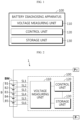
- FIG. 1 is a diagram schematically showing a battery diagnosing apparatus 100 according to an embodiment of the present disclosure.
- FIG. 2 is a diagram schematically showing an exemplary configuration of a battery pack 1 according to another embodiment of the present disclosure.
- the battery diagnosing apparatus 100 may include a voltage measuring unit 110 and a control unit 120.
- the voltage measuring unit 110 may be configured to measure a voltage of each of a plurality of battery cells B included in a battery module BM at every voltage measurement cycle.
- the battery module BM may include one or more battery cells connected in series and/or in parallel.
- the battery cell means a physically separable one independent cell having a negative electrode terminal and a positive electrode terminal.
- one pouch-type lithium polymer cell may be regarded as a battery cell.
- the voltage measurement cycle may be a cycle preset such that the voltage measuring unit 110 measures the voltage of each of the plurality of battery cells B.
- the voltage measurement cycle may be 1 second.
- the battery module BM may include five battery cells B1 to B5.
- the voltage measuring unit 110 may be connected to a first sensing line SL1, a second sensing line SL2, a third sensing line SL3, a fourth sensing line SL4, a fifth sensing line SL5, and a sixth sensing line SL6.
- the voltage measuring unit 110 may measure the voltage of the first battery cell B1 through the first sensing line SL1 and the second sensing line SL2, and measure the voltage of the second battery cell B2 through the second sensing line SL2 and the third sensing line SL3.
- the voltage measuring unit 110 may measure the voltage of the third battery cell B3 through the third sensing line SL3 and the fourth sensing line SL4, measure the voltage of the fourth battery cell B4 through the fourth sensing line SL4 and the fifth sensing line SL5, and measure the voltage of the fifth battery cell B5 through the sensing line SL5 and the sixth sensing line SL6.
- the control unit 120 may be configured to obtain a voltage value for the plurality of battery cells B from the voltage measuring unit 110 at every voltage measurement cycle.
- the voltage measuring unit 110 and the control unit 120 may be connected to communicate with each other.
- the voltage measuring unit 110 may measure the voltage of the plurality of battery cells B at every voltage measurement cycle and transmit the measured voltage value to the control unit 120. Accordingly, the control unit 120 may obtain the voltage values for the plurality of battery cells B at every voltage measurement cycle.
- the control unit 120 may be configured to calculate a voltage change amount between the plurality of obtained voltage values for the plurality of battery cells B.
- control unit 120 may calculate a voltage change amount between the voltage values of the first to fifth battery cells B1 to B5.
- control unit 120 may be configured to calculate the voltage change amount by computing a standard deviation or dispersion between the plurality of voltage values at every the voltage measurement cycle. That is, the voltage change amount calculated by the control unit 120 may be a standard deviation or dispersion of a plurality of voltage values measured at the same time point.
- the control unit 120 may be configured to calculate a voltage change rate between the plurality of calculated voltage change amounts at every diagnosis cycle different from the voltage measurement cycle.
- the diagnosis cycle is a cycle at which the voltage change rate is calculated, and may be a cycle for diagnosing the battery module BM.
- the diagnosis cycle may be set to be greater than the voltage measurement cycle.
- the diagnosis cycle may be set to 100 seconds.
- the control unit 120 calculates a voltage change amount for the plurality of battery cells B at every voltage measurement cycle, 100 voltage change amounts may be calculated by the control unit 120 whenever a diagnosis cycle arrives.
- the control unit 120 may calculate the voltage change rate for the current diagnosis cycle by computing an average change rate of 100 voltage change amounts.
- a total of 100 voltage change amounts may be calculated from the n-1 th diagnosis cycle to the n th diagnosis cycle.
- the first to the 100 th voltage change amounts may be calculated according to the voltage measurement cycle (1 second).
- the control unit 120 may calculate the voltage change rate for the N th diagnosis cycle by computing the average change rate of the first voltage change amount and the 100 th voltage change amount using Formula 1 below.
- VRn Sm ⁇ S 1 ⁇ m
- VRn is a voltage change rate of the n th diagnosis cycle.
- m is the number of voltage change amounts calculated from the n-1 th diagnosis cycle to the n th diagnosis cycle. For example, m may be calculated as "diagnosis cycle ⁇ voltage measurement cycle”.
- Sm is a voltage change amount calculated last at the n th diagnosis cycle, and S1 is a voltage change amount calculated first at the n th diagnosis cycle.
- the diagnosis cycle is 100 seconds
- the voltage measurement cycle is 1 second
- the current diagnosis cycle is the third diagnosis cycle.
- a total of 100 voltage change amounts may be calculated. That is, in Formula 1, m may be 100 (the calculation result of "100 ⁇ 1"). Sm may be the 100 th calculated voltage change amount, and Si may be the first calculated voltage change amount.
- the voltage change rate (VR3) of the third diagnosis cycle may be calculated according to the formula of "(S 100 - S1) ⁇ 100".
- the control unit 120 may be configured to diagnose the battery module BM based on one or more voltage change rates calculated up to the current diagnosis cycle and a preset criterion change rate.
- the criterion change rate may be a voltage change rate that is a criterion for diagnosing the battery module BM as a defective state or a normal state.
- the criterion change rate may be set to correspond to the battery module BM in a BOL (Beginning of Life) state.
- the battery module BM in the BOL state means a battery module BM including one or more battery cells in the BOL state.
- control unit 120 may be configured to compare the magnitudes of the voltage change rate calculated in the current diagnosis cycle and the criterion change rate and diagnose the battery module BM according to the comparison result.
- the battery diagnosing apparatus 100 may periodically calculate a voltage change rate of the voltage change amount for the plurality of battery cells B. That is, the average change rate for the voltage distribution of the plurality of battery cells B included in the battery module BM may be calculated at each diagnosis cycle.
- the battery module BM may be diagnosed based on an average change rate (average voltage change rate) for voltage distribution and the criterion change rate. Accordingly, the battery diagnosing apparatus 100 may more accurately diagnose the state of the battery module BM by considering the voltage behavior of the plurality of battery cells B during the diagnosis cycle.
- control unit 120 provided to the battery diagnosing apparatus 100 may optionally include a processor, an application-specific integrated circuit (ASIC), another chipset, a logic circuit, a register, a communication modem, and a data processing device, and the like, known in the art to execute various control logics performed in the present disclosure.
- control logic when the control logic is implemented in software, the control unit 120 may be implemented as a set of program modules.
- the program module may be stored in a memory and executed by the control unit 120.
- the memory may be provided in or out of the control unit 120, and may be connected to the control unit 120 by various well-known means.
- the battery diagnosing apparatus 100 may further include a storage unit 130.
- the storage unit 130 may store data or programs necessary for operation and function of each component of the battery diagnosing apparatus 100, data generated in the process of performing the operation or function, or the like.
- the storage unit 130 is not particularly limited in its kind as long as it is a known information storage means that can record, erase, update and read data.
- the information storage means may include RAM, flash memory, ROM, EEPROM, registers, and the like.
- the storage unit 130 may store program codes in which processes executable by the control unit 120 are defined.
- the voltages of the plurality of battery cells B measured by the voltage measuring unit 110 at every voltage measurement cycle and the voltage change amount calculated by the control unit 120 may be stored in the storage unit 130.
- the criterion change rate for the battery module BM in the BOL state may also be stored in advance in the storage unit 130.
- the control unit 120 may access the storage unit 130 to obtain the plurality of voltage change amounts calculated during the diagnosis cycle and obtain the preset criterion change rate.
- control unit 120 diagnoses the battery module BM.
- the voltage measurement cycle is 1 second
- the diagnosis cycle is 100 seconds
- the current diagnosis cycle is the fifth diagnosis cycle.
- the first voltage change rate may be calculated for the first diagnosis cycle (1 sec to 100 sec)
- the second voltage change rate may be calculated for the second diagnosis cycle (101 sec to 200 sec).
- the third voltage change rate may be calculated for the third diagnosis cycle (201 sec to 300 sec)
- the fourth voltage change rate may be calculated for the fourth diagnosis cycle (301 sec to 400 sec)
- the fifth voltage change rate may be calculated for the fifth diagnosis cycle (401 sec to 500 sec).
- the control unit 120 may be configured to compare the magnitudes of the voltage change rate calculated at the current diagnosis cycle and the criterion change rate and diagnose the battery module BM according to the comparison result.
- control unit 120 may be configured to diagnose the battery module BM as a normal module.
- the control unit 120 may diagnose the battery module BM as a normal module.
- the control unit 120 may diagnose the battery module BM as in a normal state without comparing the voltage change rate of the current diagnosis cycle with the voltage change rate of the previous diagnosis cycle.
- control unit 120 may be configured to diagnose the battery module BM based on a reference change rate preset at a previous diagnosis cycle and the voltage change rate.
- control unit 120 may be configured to preset a largest voltage change rate among one or more voltage change rates calculated at the previous diagnosis cycle as the reference change rate.
- the control unit 120 may preset the third voltage change rate having the largest magnitude among the first to fourth voltage change rates before the fifth diagnosis cycle as the reference change rate.
- the control unit 120 may be configured to diagnose the battery module BM as the normal module, when the voltage change rate is greater than or equal to the criterion change rate and less than the reference change rate.
- the control unit 120 may diagnose the battery module BM as a normal module at the fifth diagnosis cycle. That is, at the fifth diagnosis cycle, when the fifth voltage change rate of the plurality of battery cells B is equal to or greater than the criterion change rate but less than the reference change rate (the third voltage change rate), the control unit 120 may judge that the change rate with respect to the voltage deviation of the plurality of battery cells B is not increased compared to the previous diagnosis cycle. Accordingly, when the voltage change rate of the current cycle is greater than or equal to the criterion change rate but less than the reference change rate, the control unit 120 may diagnose the battery module BM as a normal module.
- control unit 120 may be configured to diagnose the battery module BM as a defective module, when the voltage change rate is equal to or greater than the criterion change rate and the reference change rate.
- the control unit 120 may judge that the change rate with respect to the voltage deviation of the plurality of battery cells B is equal to or greater than the criterion change rate and is increasing compared to the previous diagnosis cycle. That is, the control unit 120 may judge that the degree of degradation is non-uniform among the plurality of battery cells B included in the battery module BM at the current cycle. Accordingly, the control unit 120 may diagnose the battery module BM as a defective module.
- the battery diagnosing apparatus 100 may diagnose the battery module BM as a normal module without considering the reference change rate. In addition, the battery diagnosing apparatus 100 may diagnose the battery module BM as a normal module, when the voltage change rate is greater than or equal to the criterion change rate and less than the reference change rate. Finally, the battery diagnosing apparatus 100 may diagnose the battery module BM as a defective module, when the voltage change rate is equal to or greater than the criterion change rate and the reference change rate.
- the battery diagnosing apparatus 100 may consider all of the voltage change rate of the current diagnosis cycle, the criterion change rate and the reference change rate in the process of diagnosing the state of the battery module BM. By comparing the voltage change rate and the criterion change rate, the current state of the battery module BM may be diagnosed in comparison to the battery module BM in the BOL state. In addition, the state of the battery module BM for non-uniform degradation of the plurality of battery cells B may be diagnosed by comparing the voltage change rate and the reference change rate. Therefore, the battery diagnosing apparatus 100 has an advantage of diagnosing the state of the battery module BM at the current diagnosis cycle in more various aspects.
- control unit 120 may be configured to set the largest voltage change rate among one or more voltage change rates calculated before the current diagnosis cycle as the reference change rate.
- control unit 120 calculates the first to fifth voltage change rates, and the fifth voltage change rate is calculated most recently.
- the control unit 120 may set the voltage change rate having the largest magnitude among the first to fourth voltage change rates excluding the fifth voltage change rate as the reference change rate.
- the first voltage change rate is set as the reference change rate.
- the control unit 120 may be configured to compare the magnitudes of the reference change rate and the voltage change rate, and diagnose the battery module BM according to the comparison result.
- the control unit 120 may be configured to diagnose the battery module BM as a defective module. For example, when the fifth voltage change rate set as the voltage change rate is equal to or greater than the first voltage change rate set as the reference change rate, the state of the battery module BM may be diagnosed as a defective module.
- the control unit 120 may be configured to diagnose the battery module BM as a normal module. For example, when the fifth voltage change rate set as the voltage change rate is less than the first voltage change rate set as the reference change rate, the state of the battery module BM may be diagnosed as a normal module.
- the control unit 120 may diagnose the battery module BM as a defective module.
- the case where the voltage change rate increases may be a case where the voltage change amount (standard deviation or dispersion) for the plurality of battery cells B increases.
- the battery diagnosing apparatus may diagnose the battery module BM according to the result of comparing the voltage change rate and the reference change rate.
- control unit 120 may be configured to diagnose each of the plurality of battery cells B based on a voltage value corresponding to each of the plurality of battery cells B, in parallel with diagnosing the battery module BM, at every the voltage measurement cycle.
- an upper limit voltage value and a lower limit voltage value for the voltage of the battery cell may be preset.
- the control unit 120 may diagnose a battery cell in which the voltage value received from the voltage measuring unit 110 is equal to or greater than the upper limit voltage value as an overvoltage state. Also, the control unit 120 may diagnose a battery cell in which the received voltage value is equal to or less than the lower limit voltage value as a low voltage state. The control unit 120 may diagnose a battery cell in which the voltage value is less than the upper limit voltage value and exceeds the lower limit voltage value as a normal state.
- control unit 120 may diagnose the state of the battery module BM at every diagnosis cycle, and may also diagnose the state of each of the plurality of battery cells B at every voltage measurement cycle.
- control unit 120 adjusts a counting value and diagnoses the battery module BM according to the adjusted counting value will be described.
- the control unit 120 may be configured to determine the state of the battery module BM based on at least one of the voltage change rate, the criterion change rate and the reference change rate at every the diagnosis cycle, and adjust a preset counting value according to the determined state of the battery module BM.
- the counting value may have an initial value and a minimum value set to 0.
- the counting value may be adjusted by increasing or decreasing by 1 by the control unit 120.
- the control unit 120 may be configured to conservatively diagnose the battery module BM as a defective state according to stricter standards.
- control unit 120 may be configured to decrease the counting value, when the voltage change rate is less than the criterion change rate.
- the control unit 120 may diagnose the battery module BM as a normal module. If the existing counting value is 0, since the counting value cannot be decreased anymore (because the minimum value is set to 0), the counting value may be maintained at 0.
- control unit 120 may be configured to decrease the counting value, when the voltage change rate is greater than or equal to the criterion change rate and less than the reference change rate. In this case, the control unit 120 may diagnose the battery module BM as a normal module.
- control unit 120 may be configured to increase the counting value, when the voltage change rate is equal to or greater than the criterion change rate and the reference change rate. In this case, the control unit 120 may be configured to diagnose the battery module BM based on the adjusted counting value and a preset criterion value without immediately diagnosing the battery module BM as a defective module.
- the criterion value is a preset value and may be set as a natural number.
- control unit 120 may be configured to diagnose the battery module BM as the defective module, when the adjusted counting value is equal to or greater than the criterion value.
- the counting value when the voltage change rate is equal to or greater than the criterion change rate and the reference change rate, the counting value may be increased.
- the adjusted counting value is equal to or greater than the criterion value
- the battery module BM may be diagnosed as a defective module. That is, the control unit 120 may be configured to diagnose the battery module BM as a defective module, when the case where the voltage change rate is equal to or greater than the criterion change rate and the reference change rate occurs by the criterion value or more. Accordingly, since the control unit 120 diagnoses the battery module BM as a defective module through strict criteria, the possibility of erroneously diagnosing a normal module as a defective module may be significantly reduced.
- the control unit 120 may reduce the counting value. That is, in this case, the adjusted counting value is inevitably less than the criterion value. Accordingly, the control unit 120 may diagnose the battery module BM as a normal module even if the adjusted counting value and the criterion value are not compared, in order to prevent unnecessary waste of system resources by using system resources more efficiently.
- the battery diagnosing apparatus 100 may diagnose the battery module BM as a defective module through strict criteria based on the counting value and the criterion value. Accordingly, the battery diagnosing apparatus may prevent a normal module from being erroneously diagnosed as a defective module.
- the battery diagnosing apparatus 100 may be applied to a BMS (Battery Management System). That is, the BMS according to the present disclosure may include the battery diagnosing apparatus 100 described above. In this configuration, at least some components of the battery diagnosing apparatus 100 may be implemented by supplementing or adding functions of the configuration included in the conventional BMS. For example, the voltage measuring unit 110, the control unit 120 and the storage unit 130 of the battery diagnosing apparatus 100 may be implemented as components of the BMS.
- the battery diagnosing apparatus 100 may be provided to a battery pack 1.
- the battery pack 1 according to the present disclosure may include the battery diagnosing apparatus 100 and a battery module BM.
- the battery pack 1 may further include electrical equipment (a relay, a fuse, etc.) and a case.
- FIG. 3 is a diagram schematically showing a battery diagnosing method according to still another embodiment of the present disclosure.
- each step of the battery diagnosing method may be performed by the battery diagnosing apparatus 100.
- the battery diagnosing apparatus 100 Preferably, each step of the battery diagnosing method may be performed by the battery diagnosing apparatus 100.
- content overlapping with the previously described content will be omitted or briefly described.
- the battery diagnosing method may include a voltage measuring step (S 100), a voltage change amount calculating step (S200), a voltage change rate calculating step (S300), and a battery module diagnosing step (S400).
- the voltage measuring step S 100 is a step of measuring a voltage of each of a plurality of battery cells B included in a battery module BM at every voltage measurement cycle, and may be performed by the voltage measuring unit 110.
- the voltage change amount calculating step (S200) is a step of calculating a voltage change amount between the plurality of voltage values for the plurality of battery cells B at every voltage measurement cycle, and may be performed by the control unit 120.
- the control unit 120 may receive the plurality of voltage values for the plurality of battery cells B from the voltage measuring unit 110 and calculate a voltage change amount between the plurality of received voltage values.
- control unit 120 may calculate a voltage change amount by computing a dispersion or standard deviation between the plurality of voltage values.
- the voltage change rate calculating step (S300) is a step of calculating a voltage change rate between the plurality of calculated voltage change amounts at every diagnosis cycle different from the voltage measurement cycle, and may be performed by the control unit 120.
- the control unit 120 may calculate a voltage change amount of the plurality of voltage values for the plurality of battery cells B measured at every 1 second. In addition, the control unit 120 may calculate a voltage change rate for the plurality of voltage change amounts at every 100 seconds. In this case, the control unit 120 may calculate a voltage change rate for 100 voltage change amounts at every 100 seconds.
- control unit 120 may calculate the voltage change rate for the corresponding diagnosis cycle by computing an average change rate between the first calculated voltage change amount and the last calculated voltage change amount in the corresponding diagnosis cycle.
- the battery module diagnosing step (S400) is a step of diagnosing the battery module BM based on one or more voltage change rates calculated up to the current diagnosis cycle and a preset criterion change rate, and may be performed by the control unit 120.
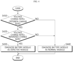
- FIG. 4 is a diagram schematically showing an embodiment of the battery module diagnosing step (S400) in the battery diagnosing method according to still another embodiment of the present disclosure.
- the battery module diagnosing step (S400) may include Step S410 to Step S440.
- Step S410 the voltage change rate and the criterion change rate may be compared. Specifically, the magnitudes of the voltage change rate calculated at the current diagnosis cycle and the criterion change rate may be compared. If the voltage change rate is equal to or greater than the criterion change rate, Step S420 may be performed, and if the voltage change rate is less than the criterion change rate, Step S440 may be performed.
- Step S420 the voltage change rate and the reference change rate may be compared. Specifically, the magnitudes of the voltage change rate calculated at the current diagnosis cycle and the reference change rate preset before the current diagnosis cycle may be compared. That is, the magnitudes of the voltage change rate calculated at the current diagnosis cycle and the reference change rate having a largest magnitude among one or more voltage change rates calculated at the previous diagnosis cycle may be compared. If the voltage change rate is equal to or greater than the reference change rate, Step S430 may be performed, and if the voltage change rate is less than the criterion change rate, Step S440 may be performed.
- the battery module BM may be diagnosed as a defective module. That is, if the voltage change rate is equal to or greater than the criterion change rate and the reference change rate, the control unit 120 may diagnose the battery module BM as a defective module.
- the battery module BM may be diagnosed as a normal module. That is, if the voltage change rate is less than the criterion change rate, or if the voltage change rate is equal to or greater than the criterion change rate but less than the reference change rate, the control unit 120 may diagnose the battery module BM as a normal module.
- FIG. 5 is a diagram schematically showing another embodiment of the battery module diagnosing step (S400) in the battery diagnosing method according to still another embodiment of the present disclosure.
- the battery module diagnosing step (S400) may include Step S410 to Step S470.
- Step S410 the embodiment of FIG. 5 will be described with a focus on the difference from the embodiment of FIG. 4 .
- Step S410 if the voltage change rate is greater than or equal to the criterion change rate, Step S420 may be performed, and if the voltage change rate is less than the criterion change rate, Step S460 may be performed.
- Step S420 if the voltage change rate is equal to or greater than the reference change rate, Step S450 may be performed, and if the voltage change rate is less than the reference change rate, Step S460 may be performed.
- the counting value may be increased.
- the counting value may have an initial value and a minimum value set to 0, and may be increased by 1. That is, if the voltage change rate is equal to or greater than the criterion change rate and the reference change rate, the control unit 120 may increase the counting value. After the counting value is increased, Step S470 may be performed.
- Step S470 the counting value and the criterion value may be compared. Specifically, if the counting value increased in Step S450 is greater than or equal to the criterion value, Step S430 may be performed. Conversely, if the counting value increased in Step S450 is less than the criterion value, Step S440 may be performed.
- Step S460 the counting value may be decreased. That is, if the voltage change rate is less than the criterion change rate, or if the voltage change rate is equal to or greater than the criterion change rate but less than the reference change rate, the control unit 120 may decrease the counting value. However, the counting value may not decrease below the set minimum value.
- Step S440 may be performed so that the battery module BM may be diagnosed as a normal module.
- the embodiments of the present disclosure described above may not be implemented only through an apparatus and a method, but may be implemented through a program that realizes a function corresponding to the configuration of the embodiments of the present disclosure or a recording medium on which the program is recorded.
- the program or recording medium may be easily implemented by those skilled in the art from the above description of the embodiments.
Landscapes
- Physics & Mathematics (AREA)
- General Physics & Mathematics (AREA)
- Engineering & Computer Science (AREA)
- Manufacturing & Machinery (AREA)
- Chemical & Material Sciences (AREA)
- Chemical Kinetics & Catalysis (AREA)
- Electrochemistry (AREA)
- General Chemical & Material Sciences (AREA)
- Power Engineering (AREA)
- Secondary Cells (AREA)
- Charge And Discharge Circuits For Batteries Or The Like (AREA)
- Tests Of Electric Status Of Batteries (AREA)
- Measurement Of Current Or Voltage (AREA)
Abstract
Description
- The present application claims priority to
Korean Patent Application No. 10-2020-0184947 filed on December 28, 2020 - The present disclosure relates to a battery diagnosing apparatus and method, and more particularly, to a battery diagnosing apparatus and method capable of diagnosing a state of a battery module based on voltage behavior of a plurality of battery cells included in the battery module.
- Recently, the demand for portable electronic products such as notebook computers, video cameras and portable telephones has increased sharply, and electric vehicles, energy storage batteries, robots, satellites and the like have been developed in earnest. Accordingly, high-performance batteries allowing repeated charging and discharging are being actively studied.
- Batteries commercially available at present include nickel-cadmium batteries, nickel hydrogen batteries, nickel-zinc batteries, lithium batteries and the like. Among them, the lithium batteries are in the limelight since they have almost no memory effect compared to nickel-based batteries and also have very low self-charging rate and high energy density.
- Conventionally, the state of the battery is diagnosed in consideration of voltage, temperature and current change amounts of the battery. In particular, based on the result of comparing the voltage of the battery with a criterion value, it is monitored whether the battery has overvoltage and/or low voltage.
- However, conventionally, since the state of the battery is diagnosed according to the voltage of the battery at a specific time point, the voltage fluctuation trend of the battery cannot be grasped, and it is difficult to diagnose the state of the battery according to the voltage fluctuation trend.
- The present disclosure is designed to solve the problems of the related art, and therefore the present disclosure is directed to providing a battery diagnosing apparatus and method capable of diagnosing a state of a battery module based on voltage fluctuation trends of a plurality of battery cells.
- These and other objects and advantages of the present disclosure may be understood from the following detailed description and will become more fully apparent from the exemplary embodiments of the present disclosure. Also, it will be easily understood that the objects and advantages of the present disclosure may be realized by the means shown in the appended claims and combinations thereof.
- A battery diagnosing apparatus according to one aspect of the present disclosure may comprise: a voltage measuring unit configured to measure a voltage of each of a plurality of battery cells included in a battery module at every voltage measurement cycle; and a control unit configured to obtain a voltage value for the plurality of battery cells from the voltage measuring unit at every voltage measurement cycle, calculate a voltage change amount between the plurality of obtained voltage values for the plurality of battery cells, calculate a voltage change rate between the plurality of calculated voltage change amounts at every diagnosis cycle different from the voltage measurement cycle, and diagnose the battery module based on one or more voltage change rates calculated up to a current diagnosis cycle and a preset criterion change rate.
- The control unit may be configured to compare magnitudes of the voltage change rate calculated at the current diagnosis cycle and the criterion change rate, and diagnose a state of the battery module based on the comparison result.
- The control unit may be configured to diagnose the battery module based on a reference change rate preset at a previous diagnosis cycle and the voltage change rate, when the voltage change rate is equal to or greater than the criterion change rate.
- The control unit may be configured to diagnose the battery module as a normal module, when the voltage change rate is less than the criterion change rate.
- The control unit may be configured to preset a largest voltage change rate among one or more voltage change rates calculated at the previous diagnosis cycle as the reference change rate.
- The control unit may be configured to diagnose the battery module as a defective module, when the voltage change rate is equal to or greater than the criterion change rate and the reference change rate.
- The control unit may be configured to diagnose the battery module as the normal module, when the voltage change rate is equal to or greater than the criterion change rate and less than the reference change rate.
- The control unit may be configured to determine a state of the battery module based on at least one of the voltage change rate, the criterion change rate and the reference change rate at every diagnosis cycle, adjust a preset counting value according to the determined state of the battery module, and diagnose the battery module based on the adjusted counting value and a preset criterion value.
- The control unit may be configured to diagnose the battery module as the defective module, when the adjusted counting value is equal to or greater than the criterion value.
- The control unit may be configured to decrease the counting value, when the voltage change rate is less than the criterion change rate.
- The control unit may be configured to decrease the counting value, when the voltage change rate is equal to or greater than the criterion change rate and less than the reference change rate.
- The control unit may be configured to increase the counting value, when the voltage change rate is equal to or greater than the criterion change rate and the reference change rate.
- The diagnosis cycle may be set to be greater than the voltage measurement cycle.
- A battery pack according to another aspect of the present disclosure may comprise the battery diagnosing apparatus according to one aspect of the present disclosure.
- A battery diagnosing method according to still another aspect of the present disclosure may comprise: a voltage measuring step of measuring a voltage of each of a plurality of battery cells included in a battery module at every voltage measurement cycle; a voltage change amount calculating step of calculating a voltage change amount between the plurality of voltage values for the plurality of battery cells at every voltage measurement cycle; a voltage change rate calculating step of calculating a voltage change rate between the plurality of calculated voltage change amounts at every diagnosis cycle different from the voltage measurement cycle; and a battery module diagnosing step of diagnosing the battery module based on one or more voltage change rates calculated up to a current diagnosis cycle and a preset criterion change rate.
- According to an aspect of the present disclosure, the state of the battery module may be diagnosed based on the voltage behavior of a plurality of battery cells included in the battery module.
- The effects of the present disclosure are not limited to the effects mentioned above, and other effects not mentioned will be clearly understood by those skilled in the art from the description of the claims.
- The accompanying drawings illustrate a preferred embodiment of the present disclosure and together with the foregoing disclosure, serve to provide further understanding of the technical features of the present disclosure, and thus, the present disclosure is not construed as being limited to the drawing.
-
FIG. 1 is a diagram schematically showing a battery diagnosing apparatus according to an embodiment of the present disclosure. -
FIG. 2 is a diagram schematically showing an exemplary configuration of a battery pack according to another embodiment of the present disclosure. -
FIG. 3 is a diagram schematically showing a battery diagnosing method according to still another embodiment of the present disclosure. -
FIG. 4 is a diagram schematically showing an embodiment of a battery module diagnosing step in the battery diagnosing method according to still another embodiment of the present disclosure. -
FIG. 5 is a diagram schematically showing another embodiment of the battery module diagnosing step in the battery diagnosing method according to still another embodiment of the present disclosure. - It should be understood that the terms used in the specification and the appended claims should not be construed as limited to general and dictionary meanings, but interpreted based on the meanings and concepts corresponding to technical aspects of the present disclosure on the basis of the principle that the inventor is allowed to define terms appropriately for the best explanation.
- Therefore, the description proposed herein is just a preferable example for the purpose of illustrations only, not intended to limit the scope of the disclosure, so it should be understood that other equivalents and modifications could be made thereto without departing from the scope of the disclosure.
- Additionally, in describing the present disclosure, when it is deemed that a detailed description of relevant known elements or functions renders the key subject matter of the present disclosure ambiguous, the detailed description is omitted herein.
- The terms including the ordinal number such as "first", "second" and the like, may be used to distinguish one element from another among various elements, but not intended to limit the elements by the terms.
- Throughout the specification, when a portion is referred to as "comprising" or "including" any element, it means that the portion may include other elements further, without excluding other elements, unless specifically stated otherwise.
- In addition, throughout the specification, when a portion is referred to as being "connected" to another portion, it is not limited to the case that they are "directly connected", but it also includes the case where they are "indirectly connected" with another element being interposed between them.
- Hereinafter, preferred embodiments of the present disclosure will be described in detail with reference to the accompanying drawings.
-
FIG. 1 is a diagram schematically showing abattery diagnosing apparatus 100 according to an embodiment of the present disclosure.FIG. 2 is a diagram schematically showing an exemplary configuration of abattery pack 1 according to another embodiment of the present disclosure. - Referring to
FIG. 1 , thebattery diagnosing apparatus 100 may include avoltage measuring unit 110 and acontrol unit 120. - The
voltage measuring unit 110 may be configured to measure a voltage of each of a plurality of battery cells B included in a battery module BM at every voltage measurement cycle. - Here, the battery module BM may include one or more battery cells connected in series and/or in parallel. In addition, the battery cell means a physically separable one independent cell having a negative electrode terminal and a positive electrode terminal. For example, one pouch-type lithium polymer cell may be regarded as a battery cell.
- Also, the voltage measurement cycle may be a cycle preset such that the
voltage measuring unit 110 measures the voltage of each of the plurality of battery cells B. For example, the voltage measurement cycle may be 1 second. - For example, in the embodiment of
FIG. 2 , the battery module BM may include five battery cells B1 to B5. - Also, in the embodiment of
FIG. 2 , thevoltage measuring unit 110 may be connected to a first sensing line SL1, a second sensing line SL2, a third sensing line SL3, a fourth sensing line SL4, a fifth sensing line SL5, and a sixth sensing line SL6. Thevoltage measuring unit 110 may measure the voltage of the first battery cell B1 through the first sensing line SL1 and the second sensing line SL2, and measure the voltage of the second battery cell B2 through the second sensing line SL2 and the third sensing line SL3. In addition, thevoltage measuring unit 110 may measure the voltage of the third battery cell B3 through the third sensing line SL3 and the fourth sensing line SL4, measure the voltage of the fourth battery cell B4 through the fourth sensing line SL4 and the fifth sensing line SL5, and measure the voltage of the fifth battery cell B5 through the sensing line SL5 and the sixth sensing line SL6. - The
control unit 120 may be configured to obtain a voltage value for the plurality of battery cells B from thevoltage measuring unit 110 at every voltage measurement cycle. - For example, in the embodiment of
FIG. 2 , thevoltage measuring unit 110 and thecontrol unit 120 may be connected to communicate with each other. Thevoltage measuring unit 110 may measure the voltage of the plurality of battery cells B at every voltage measurement cycle and transmit the measured voltage value to thecontrol unit 120. Accordingly, thecontrol unit 120 may obtain the voltage values for the plurality of battery cells B at every voltage measurement cycle. - The
control unit 120 may be configured to calculate a voltage change amount between the plurality of obtained voltage values for the plurality of battery cells B. - For example, in the embodiment of
FIG. 2 , thecontrol unit 120 may calculate a voltage change amount between the voltage values of the first to fifth battery cells B1 to B5. - Specifically, the
control unit 120 may be configured to calculate the voltage change amount by computing a standard deviation or dispersion between the plurality of voltage values at every the voltage measurement cycle. That is, the voltage change amount calculated by thecontrol unit 120 may be a standard deviation or dispersion of a plurality of voltage values measured at the same time point. - The
control unit 120 may be configured to calculate a voltage change rate between the plurality of calculated voltage change amounts at every diagnosis cycle different from the voltage measurement cycle. - Here, the diagnosis cycle is a cycle at which the voltage change rate is calculated, and may be a cycle for diagnosing the battery module BM. Preferably, the diagnosis cycle may be set to be greater than the voltage measurement cycle. For example, the diagnosis cycle may be set to 100 seconds.
- For example, as in the previous embodiment, it is assumed that the voltage measurement cycle is 1 second and the diagnosis cycle is 100 seconds. Since the
control unit 120 calculates a voltage change amount for the plurality of battery cells B at every voltage measurement cycle, 100 voltage change amounts may be calculated by thecontrol unit 120 whenever a diagnosis cycle arrives. Thecontrol unit 120 may calculate the voltage change rate for the current diagnosis cycle by computing an average change rate of 100 voltage change amounts. - Specifically, a total of 100 voltage change amounts may be calculated from the n-1th diagnosis cycle to the nth diagnosis cycle. For example, the first to the 100th voltage change amounts may be calculated according to the voltage measurement cycle (1 second). The
control unit 120 may calculate the voltage change rate for the Nth diagnosis cycle by computing the average change rate of the first voltage change amount and the 100th voltage changeamount using Formula 1 below.
- Here, VRn is a voltage change rate of the nth diagnosis cycle. m is the number of voltage change amounts calculated from the n-1th diagnosis cycle to the nth diagnosis cycle. For example, m may be calculated as "diagnosis cycle ÷ voltage measurement cycle". Sm is a voltage change amount calculated last at the nth diagnosis cycle, and S1 is a voltage change amount calculated first at the nth diagnosis cycle.
- For example, it is assumed that the diagnosis cycle is 100 seconds, the voltage measurement cycle is 1 second, and the current diagnosis cycle is the third diagnosis cycle. At the third diagnosis cycle, a total of 100 voltage change amounts may be calculated. That is, in
Formula 1, m may be 100 (the calculation result of "100 ÷ 1"). Sm may be the 100th calculated voltage change amount, and Si may be the first calculated voltage change amount. According toFormula 1, the voltage change rate (VR3) of the third diagnosis cycle may be calculated according to the formula of "(S 100 - S1) ÷ 100". - The
control unit 120 may be configured to diagnose the battery module BM based on one or more voltage change rates calculated up to the current diagnosis cycle and a preset criterion change rate. - Here, the criterion change rate may be a voltage change rate that is a criterion for diagnosing the battery module BM as a defective state or a normal state. Preferably, the criterion change rate may be set to correspond to the battery module BM in a BOL (Beginning of Life) state. Here, the battery module BM in the BOL state means a battery module BM including one or more battery cells in the BOL state.
- For example, the
control unit 120 may be configured to compare the magnitudes of the voltage change rate calculated in the current diagnosis cycle and the criterion change rate and diagnose the battery module BM according to the comparison result. - The
battery diagnosing apparatus 100 according to an embodiment of the present disclosure may periodically calculate a voltage change rate of the voltage change amount for the plurality of battery cells B. That is, the average change rate for the voltage distribution of the plurality of battery cells B included in the battery module BM may be calculated at each diagnosis cycle. In addition, the battery module BM may be diagnosed based on an average change rate (average voltage change rate) for voltage distribution and the criterion change rate. Accordingly, thebattery diagnosing apparatus 100 may more accurately diagnose the state of the battery module BM by considering the voltage behavior of the plurality of battery cells B during the diagnosis cycle. - Meanwhile, the
control unit 120 provided to thebattery diagnosing apparatus 100 may optionally include a processor, an application-specific integrated circuit (ASIC), another chipset, a logic circuit, a register, a communication modem, and a data processing device, and the like, known in the art to execute various control logics performed in the present disclosure. In addition, when the control logic is implemented in software, thecontrol unit 120 may be implemented as a set of program modules. At this time, the program module may be stored in a memory and executed by thecontrol unit 120. The memory may be provided in or out of thecontrol unit 120, and may be connected to thecontrol unit 120 by various well-known means. - In addition, the
battery diagnosing apparatus 100 may further include astorage unit 130. Thestorage unit 130 may store data or programs necessary for operation and function of each component of thebattery diagnosing apparatus 100, data generated in the process of performing the operation or function, or the like. Thestorage unit 130 is not particularly limited in its kind as long as it is a known information storage means that can record, erase, update and read data. As an example, the information storage means may include RAM, flash memory, ROM, EEPROM, registers, and the like. In addition, thestorage unit 130 may store program codes in which processes executable by thecontrol unit 120 are defined. - For example, the voltages of the plurality of battery cells B measured by the
voltage measuring unit 110 at every voltage measurement cycle and the voltage change amount calculated by thecontrol unit 120 may be stored in thestorage unit 130. In addition, the criterion change rate for the battery module BM in the BOL state may also be stored in advance in thestorage unit 130. Thecontrol unit 120 may access thestorage unit 130 to obtain the plurality of voltage change amounts calculated during the diagnosis cycle and obtain the preset criterion change rate. - Hereinafter, an embodiment in which the
control unit 120 diagnoses the battery module BM will be described. - First, it is assumed that the voltage measurement cycle is 1 second, the diagnosis cycle is 100 seconds, and the current diagnosis cycle is the fifth diagnosis cycle. The first voltage change rate may be calculated for the first diagnosis cycle (1 sec to 100 sec), and the second voltage change rate may be calculated for the second diagnosis cycle (101 sec to 200 sec). In addition, the third voltage change rate may be calculated for the third diagnosis cycle (201 sec to 300 sec), the fourth voltage change rate may be calculated for the fourth diagnosis cycle (301 sec to 400 sec), and the fifth voltage change rate may be calculated for the fifth diagnosis cycle (401 sec to 500 sec).
- The
control unit 120 may be configured to compare the magnitudes of the voltage change rate calculated at the current diagnosis cycle and the criterion change rate and diagnose the battery module BM according to the comparison result. - Specifically, when the voltage change rate is less than the criterion change rate, the
control unit 120 may be configured to diagnose the battery module BM as a normal module. - For example, when the fifth voltage change rate calculated at the current diagnosis cycle is less than the criterion change rate, the
control unit 120 may diagnose the battery module BM as a normal module. - That is, when the voltage change rate of the plurality of battery cells B calculated at the current diagnosis cycle is less than the criterion change rate, the
control unit 120 may diagnose the battery module BM as in a normal state without comparing the voltage change rate of the current diagnosis cycle with the voltage change rate of the previous diagnosis cycle. - Conversely, if the voltage change rate is greater than or equal to the criterion change rate, the
control unit 120 may be configured to diagnose the battery module BM based on a reference change rate preset at a previous diagnosis cycle and the voltage change rate. - Here, the
control unit 120 may be configured to preset a largest voltage change rate among one or more voltage change rates calculated at the previous diagnosis cycle as the reference change rate. - For example, it is assumed that the third voltage change rate is largest among the first to fourth voltage change rates. The
control unit 120 may preset the third voltage change rate having the largest magnitude among the first to fourth voltage change rates before the fifth diagnosis cycle as the reference change rate. - The
control unit 120 may be configured to diagnose the battery module BM as the normal module, when the voltage change rate is greater than or equal to the criterion change rate and less than the reference change rate. - For example, when the fifth voltage change rate is equal to or greater than the criterion change rate but less than the reference change rate (the third voltage change rate), the
control unit 120 may diagnose the battery module BM as a normal module at the fifth diagnosis cycle. That is, at the fifth diagnosis cycle, when the fifth voltage change rate of the plurality of battery cells B is equal to or greater than the criterion change rate but less than the reference change rate (the third voltage change rate), thecontrol unit 120 may judge that the change rate with respect to the voltage deviation of the plurality of battery cells B is not increased compared to the previous diagnosis cycle. Accordingly, when the voltage change rate of the current cycle is greater than or equal to the criterion change rate but less than the reference change rate, thecontrol unit 120 may diagnose the battery module BM as a normal module. - Conversely, the
control unit 120 may be configured to diagnose the battery module BM as a defective module, when the voltage change rate is equal to or greater than the criterion change rate and the reference change rate. - For example, if the voltage change rate (the fifth voltage change rate) of the current diagnosis cycle (the fifth diagnosis cycle) is equal to or greater than the criterion change rate and the reference change rate (the third voltage change rate), the
control unit 120 may judge that the change rate with respect to the voltage deviation of the plurality of battery cells B is equal to or greater than the criterion change rate and is increasing compared to the previous diagnosis cycle. That is, thecontrol unit 120 may judge that the degree of degradation is non-uniform among the plurality of battery cells B included in the battery module BM at the current cycle. Accordingly, thecontrol unit 120 may diagnose the battery module BM as a defective module. - In summary, if the voltage change rate is less than the criterion change rate, the
battery diagnosing apparatus 100 may diagnose the battery module BM as a normal module without considering the reference change rate. In addition, thebattery diagnosing apparatus 100 may diagnose the battery module BM as a normal module, when the voltage change rate is greater than or equal to the criterion change rate and less than the reference change rate. Finally, thebattery diagnosing apparatus 100 may diagnose the battery module BM as a defective module, when the voltage change rate is equal to or greater than the criterion change rate and the reference change rate. - That is, the
battery diagnosing apparatus 100 may consider all of the voltage change rate of the current diagnosis cycle, the criterion change rate and the reference change rate in the process of diagnosing the state of the battery module BM. By comparing the voltage change rate and the criterion change rate, the current state of the battery module BM may be diagnosed in comparison to the battery module BM in the BOL state. In addition, the state of the battery module BM for non-uniform degradation of the plurality of battery cells B may be diagnosed by comparing the voltage change rate and the reference change rate. Therefore, thebattery diagnosing apparatus 100 has an advantage of diagnosing the state of the battery module BM at the current diagnosis cycle in more various aspects. - Meanwhile, the
control unit 120 may be configured to set the largest voltage change rate among one or more voltage change rates calculated before the current diagnosis cycle as the reference change rate. - For example, as in the previous embodiment, it is assumed that the
control unit 120 calculates the first to fifth voltage change rates, and the fifth voltage change rate is calculated most recently. Thecontrol unit 120 may set the voltage change rate having the largest magnitude among the first to fourth voltage change rates excluding the fifth voltage change rate as the reference change rate. Hereinafter, it is assumed that the first voltage change rate is set as the reference change rate. - The
control unit 120 may be configured to compare the magnitudes of the reference change rate and the voltage change rate, and diagnose the battery module BM according to the comparison result. - Specifically, when the voltage change rate is equal to or greater than the reference change rate, the
control unit 120 may be configured to diagnose the battery module BM as a defective module. For example, when the fifth voltage change rate set as the voltage change rate is equal to or greater than the first voltage change rate set as the reference change rate, the state of the battery module BM may be diagnosed as a defective module. - Conversely, when the voltage change rate is less than the reference change rate, the
control unit 120 may be configured to diagnose the battery module BM as a normal module. For example, when the fifth voltage change rate set as the voltage change rate is less than the first voltage change rate set as the reference change rate, the state of the battery module BM may be diagnosed as a normal module. - In an embodiment of the present disclosure, when the voltage change rate for the battery module BM increases, the
control unit 120 may diagnose the battery module BM as a defective module. Here, the case where the voltage change rate increases may be a case where the voltage change amount (standard deviation or dispersion) for the plurality of battery cells B increases. For example, when the voltage deviation for the plurality of battery cells B is increased due to non-uniform degradation of the plurality of battery cells B, the voltage change rate of the battery module BM may be increased. Accordingly, the battery diagnosing apparatus may diagnose the battery module BM according to the result of comparing the voltage change rate and the reference change rate. - Meanwhile, the
control unit 120 may be configured to diagnose each of the plurality of battery cells B based on a voltage value corresponding to each of the plurality of battery cells B, in parallel with diagnosing the battery module BM, at every the voltage measurement cycle. - Specifically, an upper limit voltage value and a lower limit voltage value for the voltage of the battery cell may be preset. The
control unit 120 may diagnose a battery cell in which the voltage value received from thevoltage measuring unit 110 is equal to or greater than the upper limit voltage value as an overvoltage state. Also, thecontrol unit 120 may diagnose a battery cell in which the received voltage value is equal to or less than the lower limit voltage value as a low voltage state. Thecontrol unit 120 may diagnose a battery cell in which the voltage value is less than the upper limit voltage value and exceeds the lower limit voltage value as a normal state. - That is, the
control unit 120 may diagnose the state of the battery module BM at every diagnosis cycle, and may also diagnose the state of each of the plurality of battery cells B at every voltage measurement cycle. - Accordingly, there is an advantage in that the state of each of the plurality of battery cells B and the state of the battery module BM may all be diagnosed by the battery diagnosing apparatus.
- Hereinafter, an embodiment in which the
control unit 120 adjusts a counting value and diagnoses the battery module BM according to the adjusted counting value will be described. - The
control unit 120 may be configured to determine the state of the battery module BM based on at least one of the voltage change rate, the criterion change rate and the reference change rate at every the diagnosis cycle, and adjust a preset counting value according to the determined state of the battery module BM. - Here, the counting value may have an initial value and a minimum value set to 0. In addition, the counting value may be adjusted by increasing or decreasing by 1 by the
control unit 120. - Specifically, when the battery module BM is diagnosed as a defective module by the
control unit 120, the use of the battery module BM may be stopped and replacement may be requested. That is, when the battery module BM is diagnosed as a defective module, unlike the case where the battery module BM is diagnosed as a normal module, there may be a penalty for the corresponding battery module BM. Accordingly, thecontrol unit 120 may be configured to conservatively diagnose the battery module BM as a defective state according to stricter standards. - For example, the
control unit 120 may be configured to decrease the counting value, when the voltage change rate is less than the criterion change rate. In this case, thecontrol unit 120 may diagnose the battery module BM as a normal module. If the existing counting value is 0, since the counting value cannot be decreased anymore (because the minimum value is set to 0), the counting value may be maintained at 0. - Also, the
control unit 120 may be configured to decrease the counting value, when the voltage change rate is greater than or equal to the criterion change rate and less than the reference change rate. In this case, thecontrol unit 120 may diagnose the battery module BM as a normal module. - In addition, the
control unit 120 may be configured to increase the counting value, when the voltage change rate is equal to or greater than the criterion change rate and the reference change rate. In this case, thecontrol unit 120 may be configured to diagnose the battery module BM based on the adjusted counting value and a preset criterion value without immediately diagnosing the battery module BM as a defective module. - Here, the criterion value is a preset value and may be set as a natural number.
- Specifically, the
control unit 120 may be configured to diagnose the battery module BM as the defective module, when the adjusted counting value is equal to or greater than the criterion value. - For example, when the voltage change rate is equal to or greater than the criterion change rate and the reference change rate, the counting value may be increased. In addition, if the adjusted counting value is equal to or greater than the criterion value, the battery module BM may be diagnosed as a defective module. That is, the
control unit 120 may be configured to diagnose the battery module BM as a defective module, when the case where the voltage change rate is equal to or greater than the criterion change rate and the reference change rate occurs by the criterion value or more. Accordingly, since thecontrol unit 120 diagnoses the battery module BM as a defective module through strict criteria, the possibility of erroneously diagnosing a normal module as a defective module may be significantly reduced. - However, when the voltage change rate is less than the criterion change rate or when the voltage change rate is equal to or greater than the criterion change rate but less than the reference change rate, the
control unit 120 may reduce the counting value. That is, in this case, the adjusted counting value is inevitably less than the criterion value. Accordingly, thecontrol unit 120 may diagnose the battery module BM as a normal module even if the adjusted counting value and the criterion value are not compared, in order to prevent unnecessary waste of system resources by using system resources more efficiently. - The
battery diagnosing apparatus 100 according to an embodiment of the present disclosure may diagnose the battery module BM as a defective module through strict criteria based on the counting value and the criterion value. Accordingly, the battery diagnosing apparatus may prevent a normal module from being erroneously diagnosed as a defective module. - The
battery diagnosing apparatus 100 according to the present disclosure may be applied to a BMS (Battery Management System). That is, the BMS according to the present disclosure may include thebattery diagnosing apparatus 100 described above. In this configuration, at least some components of thebattery diagnosing apparatus 100 may be implemented by supplementing or adding functions of the configuration included in the conventional BMS. For example, thevoltage measuring unit 110, thecontrol unit 120 and thestorage unit 130 of thebattery diagnosing apparatus 100 may be implemented as components of the BMS. - In addition, the
battery diagnosing apparatus 100 according to the present disclosure may be provided to abattery pack 1. For example, referring toFIG. 2 , thebattery pack 1 according to the present disclosure may include thebattery diagnosing apparatus 100 and a battery module BM. In addition, thebattery pack 1 may further include electrical equipment (a relay, a fuse, etc.) and a case. -
FIG. 3 is a diagram schematically showing a battery diagnosing method according to still another embodiment of the present disclosure. - Preferably, each step of the battery diagnosing method may be performed by the
battery diagnosing apparatus 100. Hereinafter, content overlapping with the previously described content will be omitted or briefly described. - Referring to
FIG. 3 , the battery diagnosing method may include a voltage measuring step (S 100), a voltage change amount calculating step (S200), a voltage change rate calculating step (S300), and a battery module diagnosing step (S400). - The voltage measuring
step S 100 is a step of measuring a voltage of each of a plurality of battery cells B included in a battery module BM at every voltage measurement cycle, and may be performed by thevoltage measuring unit 110. - The voltage change amount calculating step (S200) is a step of calculating a voltage change amount between the plurality of voltage values for the plurality of battery cells B at every voltage measurement cycle, and may be performed by the
control unit 120. - The
control unit 120 may receive the plurality of voltage values for the plurality of battery cells B from thevoltage measuring unit 110 and calculate a voltage change amount between the plurality of received voltage values. - For example, the
control unit 120 may calculate a voltage change amount by computing a dispersion or standard deviation between the plurality of voltage values. - The voltage change rate calculating step (S300) is a step of calculating a voltage change rate between the plurality of calculated voltage change amounts at every diagnosis cycle different from the voltage measurement cycle, and may be performed by the
control unit 120. - It is assumed that the voltage measurement cycle is 1 second and the diagnosis cycle is 100 seconds. The
control unit 120 may calculate a voltage change amount of the plurality of voltage values for the plurality of battery cells B measured at every 1 second. In addition, thecontrol unit 120 may calculate a voltage change rate for the plurality of voltage change amounts at every 100 seconds. In this case, thecontrol unit 120 may calculate a voltage change rate for 100 voltage change amounts at every 100 seconds. - For example, the
control unit 120 may calculate the voltage change rate for the corresponding diagnosis cycle by computing an average change rate between the first calculated voltage change amount and the last calculated voltage change amount in the corresponding diagnosis cycle. - The battery module diagnosing step (S400) is a step of diagnosing the battery module BM based on one or more voltage change rates calculated up to the current diagnosis cycle and a preset criterion change rate, and may be performed by the
control unit 120. -
FIG. 4 is a diagram schematically showing an embodiment of the battery module diagnosing step (S400) in the battery diagnosing method according to still another embodiment of the present disclosure. - Referring to
FIG. 4 , the battery module diagnosing step (S400) may include Step S410 to Step S440. - In Step S410, the voltage change rate and the criterion change rate may be compared. Specifically, the magnitudes of the voltage change rate calculated at the current diagnosis cycle and the criterion change rate may be compared. If the voltage change rate is equal to or greater than the criterion change rate, Step S420 may be performed, and if the voltage change rate is less than the criterion change rate, Step S440 may be performed.
- In Step S420, the voltage change rate and the reference change rate may be compared. Specifically, the magnitudes of the voltage change rate calculated at the current diagnosis cycle and the reference change rate preset before the current diagnosis cycle may be compared. That is, the magnitudes of the voltage change rate calculated at the current diagnosis cycle and the reference change rate having a largest magnitude among one or more voltage change rates calculated at the previous diagnosis cycle may be compared. If the voltage change rate is equal to or greater than the reference change rate, Step S430 may be performed, and if the voltage change rate is less than the criterion change rate, Step S440 may be performed.
- In Step S430, the battery module BM may be diagnosed as a defective module. That is, if the voltage change rate is equal to or greater than the criterion change rate and the reference change rate, the
control unit 120 may diagnose the battery module BM as a defective module. - In Step S440, the battery module BM may be diagnosed as a normal module. That is, if the voltage change rate is less than the criterion change rate, or if the voltage change rate is equal to or greater than the criterion change rate but less than the reference change rate, the
control unit 120 may diagnose the battery module BM as a normal module. -
FIG. 5 is a diagram schematically showing another embodiment of the battery module diagnosing step (S400) in the battery diagnosing method according to still another embodiment of the present disclosure. - Referring to
FIG. 5 , the battery module diagnosing step (S400) may include Step S410 to Step S470. Hereinafter, the embodiment ofFIG. 5 will be described with a focus on the difference from the embodiment ofFIG. 4 . - In Step S410, if the voltage change rate is greater than or equal to the criterion change rate, Step S420 may be performed, and if the voltage change rate is less than the criterion change rate, Step S460 may be performed.
- In Step S420, if the voltage change rate is equal to or greater than the reference change rate, Step S450 may be performed, and if the voltage change rate is less than the reference change rate, Step S460 may be performed.
- In Step S450, the counting value may be increased. For example, the counting value may have an initial value and a minimum value set to 0, and may be increased by 1. That is, if the voltage change rate is equal to or greater than the criterion change rate and the reference change rate, the
control unit 120 may increase the counting value. After the counting value is increased, Step S470 may be performed. - In Step S470, the counting value and the criterion value may be compared. Specifically, if the counting value increased in Step S450 is greater than or equal to the criterion value, Step S430 may be performed. Conversely, if the counting value increased in Step S450 is less than the criterion value, Step S440 may be performed.
- In Step S460, the counting value may be decreased. That is, if the voltage change rate is less than the criterion change rate, or if the voltage change rate is equal to or greater than the criterion change rate but less than the reference change rate, the
control unit 120 may decrease the counting value. However, the counting value may not decrease below the set minimum value. After Step S460, Step S440 may be performed so that the battery module BM may be diagnosed as a normal module. - The embodiments of the present disclosure described above may not be implemented only through an apparatus and a method, but may be implemented through a program that realizes a function corresponding to the configuration of the embodiments of the present disclosure or a recording medium on which the program is recorded. The program or recording medium may be easily implemented by those skilled in the art from the above description of the embodiments.
- The present disclosure has been described in detail. However, it should be understood that the detailed description and specific examples, while indicating preferred embodiments of the disclosure, are given by way of illustration only, since various changes and modifications within the scope of the disclosure will become apparent to those skilled in the art from this detailed description.
- Additionally, many substitutions, modifications and changes may be made to the present disclosure described hereinabove by those skilled in the art without departing from the technical aspects of the present disclosure, and the present disclosure is not limited to the above-described embodiments and the accompanying drawings, and each embodiment may be selectively combined in part or in whole to allow various modifications.
-
- 1: battery pack
- 100: battery diagnosing apparatus
- 110: voltage measuring unit
- 120: control unit
- 130: storage unit
- BM: battery module
- C: plurality of battery cells
Claims (13)
- A battery diagnosing apparatus, comprising:a voltage measuring unit configured to measure a voltage of each of a plurality of battery cells included in a battery module at every voltage measurement cycle; anda control unit configured to obtain a voltage value for the plurality of battery cells from the voltage measuring unit at every voltage measurement cycle, calculate a voltage change amount between the plurality of obtained voltage values for the plurality of battery cells, calculate a voltage change rate between the plurality of calculated voltage change amounts at every diagnosis cycle different from the voltage measurement cycle, and diagnose the battery module based on one or more voltage change rates calculated up to a current diagnosis cycle and a preset criterion change rate.
- The battery diagnosing apparatus according to claim 1,
wherein the control unit is configured to compare magnitudes of the voltage change rate calculated at the current diagnosis cycle and the criterion change rate, and diagnose a state of the battery module based on the comparison result. - The battery diagnosing apparatus according to claim 2,wherein the control unit is configured to diagnose the battery module based on a reference change rate preset at a previous diagnosis cycle and the voltage change rate, when the voltage change rate is equal to or greater than the criterion change rate, andwherein the control unit is configured to diagnose the battery module as a normal module, when the voltage change rate is less than the criterion change rate.
- The battery diagnosing apparatus according to claim 3,
wherein the control unit is configured to preset a largest voltage change rate among one or more voltage change rates calculated at the previous diagnosis cycle as the reference change rate. - The battery diagnosing apparatus according to claim 3,wherein the control unit is configured to diagnose the battery module as a defective module, when the voltage change rate is equal to or greater than the criterion change rate and the reference change rate, andwherein the control unit is configured to diagnose the battery module as the normal module, when the voltage change rate is equal to or greater than the criterion change rate and less than the reference change rate.
- The battery diagnosing apparatus according to claim 5,
wherein the control unit is configured to determine a state of the battery module based on at least one of the voltage change rate, the criterion change rate and the reference change rate at every diagnosis cycle, adjust a preset counting value according to the determined state of the battery module, and diagnose the battery module based on the adjusted counting value and a preset criterion value. - The battery diagnosing apparatus according to claim 6,
wherein the control unit is configured to diagnose the battery module as the defective module, when the adjusted counting value is equal to or greater than the criterion value. - The battery diagnosing apparatus according to claim 6,wherein the control unit is configured to decrease the counting value, when the voltage change rate is less than the criterion change rate,wherein the control unit is configured to decrease the counting value, when the voltage change rate is equal to or greater than the criterion change rate and less than the reference change rate, andwherein the control unit is configured to increase the counting value, when the voltage change rate is equal to or greater than the criterion change rate and the reference change rate.
- The battery diagnosing apparatus according to claim 1,
wherein the control unit is configured to calculate the voltage change amount by computing a standard deviation or dispersion of the plurality of voltage values at every voltage measurement cycle. - The battery diagnosing apparatus according to claim 1,
wherein the diagnosis cycle is set to be greater than the voltage measurement cycle. - The battery diagnosing apparatus according to claim 1,
wherein the control unit is configured to diagnose each of the plurality of battery cells based on a voltage value corresponding to each of the plurality of battery cells at every voltage measurement cycle. - A battery pack, comprising the battery diagnosing apparatus according to any one of claims 1 to 11.
- A battery diagnosing method, comprising:a voltage measuring step of measuring a voltage of each of a plurality of battery cells included in a battery module at every voltage measurement cycle;a voltage change amount calculating step of calculating a voltage change amount between the plurality of voltage values for the plurality of battery cells at every voltage measurement cycle;a voltage change rate calculating step of calculating a voltage change rate between the plurality of calculated voltage change amounts at every diagnosis cycle different from the voltage measurement cycle; anda battery module diagnosing step of diagnosing the battery module based on one or more voltage change rates calculated up to a current diagnosis cycle and a preset criterion change rate.
Applications Claiming Priority (2)
| Application Number | Priority Date | Filing Date | Title |
|---|---|---|---|
| KR1020200184947A KR20220093843A (en) | 2020-12-28 | 2020-12-28 | Apparatus and method for diagnosing battery |
| PCT/KR2021/020090 WO2022145998A1 (en) | 2020-12-28 | 2021-12-28 | Battery diagnosis device and method |
Publications (2)
| Publication Number | Publication Date |
|---|---|
| EP4202457A1 true EP4202457A1 (en) | 2023-06-28 |
| EP4202457A4 EP4202457A4 (en) | 2024-04-17 |
Family
ID=82260748
Family Applications (1)
| Application Number | Title | Priority Date | Filing Date |
|---|---|---|---|
| EP21915796.3A Pending EP4202457A4 (en) | 2020-12-28 | 2021-12-28 | Battery diagnosis device and method |
Country Status (6)
| Country | Link |
|---|---|
| US (2) | US12253572B2 (en) |
| EP (1) | EP4202457A4 (en) |
| JP (1) | JP7537824B2 (en) |
| KR (1) | KR20220093843A (en) |
| CN (1) | CN116134325B (en) |
| WO (1) | WO2022145998A1 (en) |
Cited By (1)
| Publication number | Priority date | Publication date | Assignee | Title |
|---|---|---|---|---|
| EP4621428A4 (en) * | 2022-12-22 | 2026-03-11 | Lg Energy Solution Ltd | BATTERY MANAGEMENT DEVICE AND OPERATING PROCEDURES |
Families Citing this family (5)
| Publication number | Priority date | Publication date | Assignee | Title |
|---|---|---|---|---|
| CN121114775A (en) * | 2020-11-27 | 2025-12-12 | 株式会社Lg新能源 | Battery diagnostic devices, battery diagnostic methods, battery packs and vehicles |
| KR20220118828A (en) * | 2021-02-19 | 2022-08-26 | 주식회사 엘지에너지솔루션 | Apparatus and method for battery state |
| KR102890378B1 (en) * | 2022-09-16 | 2025-11-24 | 주식회사 엘지에너지솔루션 | Battery diagnosis apparatus, battery diagnosis method, battery pack, and vehicle including the same |
| KR102792813B1 (en) * | 2023-07-13 | 2025-04-11 | 두산에너빌리티 주식회사 | Apparatus for detecting battery anomaly module using voltage drop difference and method thereof |
| TW202539936A (en) * | 2023-12-26 | 2025-10-16 | 南韓商Lg新能源股份有限公司 | Apparatus for managing battery, battery pack, vehicle, and battery providing system comprising the same |
Family Cites Families (27)
| Publication number | Priority date | Publication date | Assignee | Title |
|---|---|---|---|---|
| JP4030217B2 (en) | 1999-03-12 | 2008-01-09 | トヨタ自動車株式会社 | Abnormality determination device and abnormality determination method for battery pack |
| JP4019815B2 (en) | 2002-06-26 | 2007-12-12 | 日産自動車株式会社 | Abnormality diagnosis apparatus and method for assembled battery |
| JP5248764B2 (en) | 2006-11-02 | 2013-07-31 | パナソニック株式会社 | Storage element abnormality detection device, storage element abnormality detection method, and abnormality detection program thereof |
| KR101099811B1 (en) | 2009-03-03 | 2011-12-27 | 주식회사 엘지화학 | Method and Apparatus for checking current sensor abnormality in battery pack |
| JP5466564B2 (en) | 2010-04-12 | 2014-04-09 | 本田技研工業株式会社 | Battery degradation estimation method, battery capacity estimation method, battery capacity equalization method, and battery degradation estimation apparatus |
| US8219333B2 (en) * | 2010-06-29 | 2012-07-10 | O2Micro, Inc | Battery management systems for protecting batteries from fault conditions |
| JP2012047521A (en) | 2010-08-25 | 2012-03-08 | Nippon Soken Inc | Battery state monitor |
| WO2012078601A1 (en) * | 2010-12-06 | 2012-06-14 | Coda Automotive, Inc. | Measuring isolated high voltage and detecting isolation breakdown with measures for self-detection of circuit faults |
| CN102122740B (en) * | 2011-01-05 | 2013-09-25 | 山东申普交通科技有限公司 | Intelligent equalization charging method and intelligent equalization charging distributor of storage battery |
| WO2013002202A1 (en) * | 2011-06-29 | 2013-01-03 | 三洋電機株式会社 | Battery degradation assessment device |
| JP5668672B2 (en) | 2011-08-02 | 2015-02-12 | トヨタ自動車株式会社 | Battery system and overdischarge detection method for battery system |
| US9118191B2 (en) | 2011-08-29 | 2015-08-25 | Samsung Sdi Co., Ltd. | Cell balancing method, cell balancing device, and energy storage system including the cell balancing device |
| KR101572650B1 (en) | 2013-02-19 | 2015-12-04 | 주식회사 엘지화학 | Apparatus and method for diagnosis of battery bank's imbalancing |
| JP6206117B2 (en) | 2013-11-21 | 2017-10-04 | 日産自動車株式会社 | Battery module control device and battery module state determination method |
| KR101551062B1 (en) * | 2014-02-18 | 2015-09-07 | 현대자동차주식회사 | Apparatus and Method for diagnosing defect of battery cell |
| JP2015204217A (en) | 2014-04-15 | 2015-11-16 | トヨタ自動車株式会社 | battery system |
| JP6476724B2 (en) | 2014-10-16 | 2019-03-06 | 株式会社豊田自動織機 | Battery monitoring device |
| JP6635742B2 (en) * | 2015-10-09 | 2020-01-29 | 株式会社ピューズ | Storage battery maintenance device and storage battery maintenance method |
| JP6673035B2 (en) | 2016-06-08 | 2020-03-25 | トヨタ自動車株式会社 | Battery system |
| CN109435758B (en) * | 2017-08-31 | 2022-03-18 | 比亚迪股份有限公司 | Battery equalization method, system, vehicle, storage medium and electronic device |
| KR102441469B1 (en) | 2017-11-13 | 2022-09-06 | 주식회사 엘지에너지솔루션 | Battery charging method and battery charging device |
| KR102420091B1 (en) * | 2018-04-10 | 2022-07-12 | 주식회사 엘지에너지솔루션 | Apparatus and method for diagnosing battery cell |
| KR102493232B1 (en) * | 2019-03-18 | 2023-01-27 | 주식회사 엘지에너지솔루션 | Apparatus for managing battery |
| KR102521577B1 (en) * | 2019-03-18 | 2023-04-12 | 주식회사 엘지에너지솔루션 | Apparatus for estimating state of battery |
| KR102520673B1 (en) | 2019-03-18 | 2023-04-10 | 주식회사 엘지에너지솔루션 | Apparatus for estimating state of battery |
| KR102521576B1 (en) | 2019-03-18 | 2023-04-12 | 주식회사 엘지에너지솔루션 | Apparatus for managing battery |
| CN110794305B (en) * | 2019-10-14 | 2021-03-16 | 北京理工大学 | Power battery fault diagnosis method and system |
-
2020
- 2020-12-28 KR KR1020200184947A patent/KR20220093843A/en active Pending
-
2021
- 2021-12-28 JP JP2022581653A patent/JP7537824B2/en active Active
- 2021-12-28 CN CN202180059172.4A patent/CN116134325B/en active Active
- 2021-12-28 EP EP21915796.3A patent/EP4202457A4/en active Pending
- 2021-12-28 US US18/005,272 patent/US12253572B2/en active Active
- 2021-12-28 WO PCT/KR2021/020090 patent/WO2022145998A1/en not_active Ceased
-
2025
- 2025-03-11 US US19/076,317 patent/US20250290997A1/en active Pending
Cited By (1)
| Publication number | Priority date | Publication date | Assignee | Title |
|---|---|---|---|---|
| EP4621428A4 (en) * | 2022-12-22 | 2026-03-11 | Lg Energy Solution Ltd | BATTERY MANAGEMENT DEVICE AND OPERATING PROCEDURES |
Also Published As
| Publication number | Publication date |
|---|---|
| JP7537824B2 (en) | 2024-08-21 |
| JP2023533238A (en) | 2023-08-02 |
| WO2022145998A1 (en) | 2022-07-07 |
| US20250290997A1 (en) | 2025-09-18 |
| KR20220093843A (en) | 2022-07-05 |
| CN116134325A (en) | 2023-05-16 |
| CN116134325B (en) | 2026-05-08 |
| US12253572B2 (en) | 2025-03-18 |
| EP4202457A4 (en) | 2024-04-17 |
| US20230258735A1 (en) | 2023-08-17 |
Similar Documents
| Publication | Publication Date | Title |
|---|---|---|
| EP4206706B1 (en) | Apparatus and method for diagnosing state of battery | |
| US12210065B2 (en) | Battery diagnosing apparatus and method | |
| EP3989330B1 (en) | Apparatus and method for diagnosing degree of degradation of battery | |
| US12253572B2 (en) | Battery diagnosing apparatus and method | |
| EP4199182B1 (en) | Battery diagnosing apparatus and method | |
| EP3839536B1 (en) | Battery state estimating apparatus | |
| EP3835801B1 (en) | Battery state estimating apparatus | |
| EP4145158A1 (en) | Battery diagnosis device and method | |
| KR20230019705A (en) | Apparatus and method for managing battery | |
| EP3998489B1 (en) | Battery dod diagnosing apparatus and method | |
| EP4206707B1 (en) | Battery monitoring apparatus and method | |
| EP4131573A1 (en) | Battery diagnostic apparatus and method | |
| EP4531015A2 (en) | Battery diagnosing system and method | |
| EP4152025B1 (en) | Battery diagnosing apparatus and method | |
| EP4350374B1 (en) | Battery state estimating apparatus and method | |
| EP4382935A1 (en) | Battery management device and method | |
| EP4167345B1 (en) | Battery diagnosing apparatus and method | |
| KR20230168900A (en) | Apparatus and method for diagnosing battery | |
| EP4517353A1 (en) | Apparatus and method for diagnosing battery |
Legal Events
| Date | Code | Title | Description |
|---|---|---|---|
| STAA | Information on the status of an ep patent application or granted ep patent |
Free format text: STATUS: THE INTERNATIONAL PUBLICATION HAS BEEN MADE |
|
| PUAI | Public reference made under article 153(3) epc to a published international application that has entered the european phase |
Free format text: ORIGINAL CODE: 0009012 |
|
| STAA | Information on the status of an ep patent application or granted ep patent |
Free format text: STATUS: REQUEST FOR EXAMINATION WAS MADE |
|
| 17P | Request for examination filed |
Effective date: 20230323 |
|
| AK | Designated contracting states |
Kind code of ref document: A1 Designated state(s): AL AT BE BG CH CY CZ DE DK EE ES FI FR GB GR HR HU IE IS IT LI LT LU LV MC MK MT NL NO PL PT RO RS SE SI SK SM TR |
|
| DAV | Request for validation of the european patent (deleted) | ||
| DAX | Request for extension of the european patent (deleted) | ||
| A4 | Supplementary search report drawn up and despatched |
Effective date: 20240314 |
|
| RIC1 | Information provided on ipc code assigned before grant |
Ipc: G01R 31/392 20190101ALI20240308BHEP Ipc: G01R 19/12 20060101ALI20240308BHEP Ipc: G01R 31/3835 20190101ALI20240308BHEP Ipc: H01M 10/42 20060101ALI20240308BHEP Ipc: H01M 10/48 20060101ALI20240308BHEP Ipc: G01R 19/00 20060101ALI20240308BHEP Ipc: G01R 19/165 20060101ALI20240308BHEP Ipc: G01R 31/396 20190101ALI20240308BHEP Ipc: G01R 31/382 20190101ALI20240308BHEP Ipc: G01R 31/36 20200101AFI20240308BHEP |
|
| STAA | Information on the status of an ep patent application or granted ep patent |
Free format text: STATUS: EXAMINATION IS IN PROGRESS |
|
| 17Q | First examination report despatched |
Effective date: 20251006 |