EP4202455A1 - Pin pushing inspection connector - Google Patents
Pin pushing inspection connector Download PDFInfo
- Publication number
- EP4202455A1 EP4202455A1 EP22807630.3A EP22807630A EP4202455A1 EP 4202455 A1 EP4202455 A1 EP 4202455A1 EP 22807630 A EP22807630 A EP 22807630A EP 4202455 A1 EP4202455 A1 EP 4202455A1
- Authority
- EP
- European Patent Office
- Prior art keywords
- connector
- connector assembly
- pin
- inspection
- under test
- Prior art date
- Legal status (The legal status is an assumption and is not a legal conclusion. Google has not performed a legal analysis and makes no representation as to the accuracy of the status listed.)
- Granted
Links
Images





Classifications
-
- G—PHYSICS
- G01—MEASURING; TESTING
- G01R—MEASURING ELECTRIC VARIABLES; MEASURING MAGNETIC VARIABLES
- G01R31/00—Arrangements for testing electric properties; Arrangements for locating electric faults; Arrangements for electrical testing characterised by what is being tested not provided for elsewhere
- G01R31/50—Testing of electric apparatus, lines, cables or components for short-circuits, continuity, leakage current or incorrect line connections
- G01R31/66—Testing of connections, e.g. of plugs or non-disconnectable joints
- G01R31/68—Testing of releasable connections, e.g. of terminals mounted on a printed circuit board
- G01R31/69—Testing of releasable connections, e.g. of terminals mounted on a printed circuit board of terminals at the end of a cable or a wire harness; of plugs; of sockets, e.g. wall sockets or power sockets in appliances
-
- G—PHYSICS
- G01—MEASURING; TESTING
- G01R—MEASURING ELECTRIC VARIABLES; MEASURING MAGNETIC VARIABLES
- G01R31/00—Arrangements for testing electric properties; Arrangements for locating electric faults; Arrangements for electrical testing characterised by what is being tested not provided for elsewhere
- G01R31/50—Testing of electric apparatus, lines, cables or components for short-circuits, continuity, leakage current or incorrect line connections
- G01R31/66—Testing of connections, e.g. of plugs or non-disconnectable joints
- G01R31/68—Testing of releasable connections, e.g. of terminals mounted on a printed circuit board
-
- G—PHYSICS
- G01—MEASURING; TESTING
- G01R—MEASURING ELECTRIC VARIABLES; MEASURING MAGNETIC VARIABLES
- G01R31/00—Arrangements for testing electric properties; Arrangements for locating electric faults; Arrangements for electrical testing characterised by what is being tested not provided for elsewhere
- G01R31/28—Testing of electronic circuits, e.g. by signal tracer
- G01R31/2851—Testing of integrated circuits [IC]
- G01R31/2855—Environmental, reliability or burn-in testing
- G01R31/286—External aspects, e.g. related to chambers, contacting devices or handlers
- G01R31/2863—Contacting devices, e.g. sockets, burn-in boards or mounting fixtures
-
- G—PHYSICS
- G01—MEASURING; TESTING
- G01R—MEASURING ELECTRIC VARIABLES; MEASURING MAGNETIC VARIABLES
- G01R1/00—Details of instruments or arrangements of the types included in groups G01R5/00 - G01R13/00 and G01R31/00
- G01R1/02—General constructional details
- G01R1/04—Housings; Supporting members; Arrangements of terminals
- G01R1/0408—Test fixtures or contact fields; Connectors or connecting adaptors; Test clips; Test sockets
- G01R1/0433—Sockets for IC's or transistors
- G01R1/0441—Details
- G01R1/0466—Details concerning contact pieces or mechanical details, e.g. hinges or cams; Shielding
-
- G—PHYSICS
- G01—MEASURING; TESTING
- G01R—MEASURING ELECTRIC VARIABLES; MEASURING MAGNETIC VARIABLES
- G01R1/00—Details of instruments or arrangements of the types included in groups G01R5/00 - G01R13/00 and G01R31/00
- G01R1/02—General constructional details
- G01R1/06—Measuring leads; Measuring probes
- G01R1/067—Measuring probes
- G01R1/073—Multiple probes
-
- G—PHYSICS
- G01—MEASURING; TESTING
- G01R—MEASURING ELECTRIC VARIABLES; MEASURING MAGNETIC VARIABLES
- G01R31/00—Arrangements for testing electric properties; Arrangements for locating electric faults; Arrangements for electrical testing characterised by what is being tested not provided for elsewhere
- G01R31/28—Testing of electronic circuits, e.g. by signal tracer
- G01R31/2801—Testing of printed circuits, backplanes, motherboards, hybrid circuits or carriers for multichip packages [MCP]
- G01R31/2806—Apparatus therefor, e.g. test stations, drivers, analysers, conveyors
- G01R31/2808—Holding, conveying or contacting devices, e.g. test adapters, edge connectors, extender boards
-
- G—PHYSICS
- G01—MEASURING; TESTING
- G01R—MEASURING ELECTRIC VARIABLES; MEASURING MAGNETIC VARIABLES
- G01R31/00—Arrangements for testing electric properties; Arrangements for locating electric faults; Arrangements for electrical testing characterised by what is being tested not provided for elsewhere
- G01R31/50—Testing of electric apparatus, lines, cables or components for short-circuits, continuity, leakage current or incorrect line connections
- G01R31/66—Testing of connections, e.g. of plugs or non-disconnectable joints
-
- G—PHYSICS
- G01—MEASURING; TESTING
- G01R—MEASURING ELECTRIC VARIABLES; MEASURING MAGNETIC VARIABLES
- G01R31/00—Arrangements for testing electric properties; Arrangements for locating electric faults; Arrangements for electrical testing characterised by what is being tested not provided for elsewhere
- G01R31/50—Testing of electric apparatus, lines, cables or components for short-circuits, continuity, leakage current or incorrect line connections
- G01R31/54—Testing for continuity
Definitions
- the present disclosure relates to an inspection connector that may be used in an end of line (EOL) process in the production of various connectors, and more particularly, to a pin push inspection connector that may be used in a function test for finally checking whether there is product abnormality after the assembly of various connector products is completed and checking whether pins of an assembled connector are pushed backward from correct positions and assembled (defective state).
- EOL end of line
- a number of components are installed in a vehicle, an air conditioner, a refrigerator, a washing machine, a battery pack, or the like, and a complex wiring circuit is used to connect components to other components or supply power. Because the wiring circuit is quite complicated, it is effective to install the plurality of components and then form the wiring circuit. To this end, a cable connector implemented by connecting a plurality of cables is frequently used.
- a cable connector includes electrical cables, terminal pins connected to ends of the electrical cables, and a connector housing into which the terminal pins are inserted and fixed.
- the number of terminal pins or the size of the connector housing may vary according to a product to be applied.
- a connector In the case of a connector, a plurality of terminal pins and a plurality of cables should be correctly connected, and the terminal pins connected to the cables should be correctly inserted into a connector housing. However, in a manufacturing process, for some reasons, the terminal pins may not be inserted into the connector housing to correct positions. In this case, because signal transmission or power supply through the connector is not performed, a product using the cable connector may not operate normally.
- the present disclosure is designed to solve the problems of the related art, and therefore the present disclosure is directed to providing a means for easily determining whether a pin of a connector under test is pushed, thereby omitting X-ray imaging and Dino inspection.
- a pin push inspection connector including a first connector assembly having a front portion connected to a connector under test in a first direction and fixedly coupled to the connector under test, and a second connector assembly having a front portion connected to a rear portion of the first connector assembly in the first direction and provided so that a connection interval with respect to the first connector assembly is variably adjusted in the first direction or a second direction that is opposite to the first direction, wherein the second connector assembly includes at least one inspection pin provided therein to be connected to at least one terminal pin provided in the connector under test.
- the first connector assembly may include a first fastening hole extending in the first direction from a rear end portion of the first connector assembly, and the second connector assembly may include a length adjusting bolt passing through a body and screwed into the first fastening hole to a certain depth.
- the second connector assembly may further include a second fastening hole extending in the first direction and having a thread formed on an inner circumferential surface thereof, and a length fixing bolt screwed into the second fastening hole and provided to support the rear end portion of the first connector assembly.
- a pair of length adjusting bolts may be respectively provided on a left edge and a right edge of the second connector assembly.
- a pair of length fixing bolts may be provided between the pair of length adjusting bolts.
- the at least one inspection pin may be fixed in the second connector assembly to move integrally with the second connector assembly in the first direction or the second direction with respect to the first connector assembly.
- the first connector assembly may include a latch provided to be engaged with a locking protrusion provided on an outer portion of the connector under test.
- the first connector assembly may include a first housing including a first main body formed in a hollow structure and a first wing body integrally formed on both sides of the first main body, and a guide pin extending from the first wing body in the first direction beyond the first main body.
- the first connector assembly may include a first housing including a first main body formed in a hollow structure and a first wing body integrally formed on both sides of the first main body, and a guide pin extending from the first wing body in the first direction beyond the first main body, wherein the length fixing bolt is provided so that a front end portion of the length fixing bolt supports a rear end of the guide pin located on the first wing body.
- the at least one inspection pin may include a plurality of inspection pins, and is provided to be connected in a one-to-one plug-in manner to each terminal pin of the connector under test.
- a pin push inspection connector in which whether a terminal pin of a connector under test is pushed may be easily determined because a contact point with the terminal pin of the connector under test may be variably adjusted.
- FIG. 1 is a view illustrating a connector under test that may be inspected by a pin push inspection connector according to an embodiment of the present disclosure.
- FIG. 2 is a photograph showing a pin push inspection connector according to an embodiment of the present disclosure.
- a pin push inspection connector 100 may be used as an inspection means that is directly connected to a connector under test 200 to check whether all terminal pins P of the connector under test 200 are pushed.
- the connector under test 200 refers to a connector including a plurality of terminal pins P connected in a one-to-one manner to a plurality of cables and a housing into which the plurality of terminal pins P are inserted.
- the number and shape of terminal pins P in the connector under test 200 may be determined according to characteristics of a product to be applied, and as shown in FIG. 2 , the pin push inspection connector 100 may be connected to correspond to the connector under test 200.
- the connector under test 200 may be a sensing cable connector used in a battery module (pack) to transmit various data such as a voltage or a temperature to a battery management system (BMS).
- the pin push inspection connector 100 may be connected in a plug-in manner to the sensing cable connector, and may include the same number of inspection pins 30 as the terminal pins P of the sensing cable connector.
- the inspection pins 30 may be of a male type, and in contrast, when the terminal pins P is of a male type, the inspection pins 30 may be of a female type.
- the pin push inspection connector 100 is configured so that a contact point between the inspection pins 30 and the terminal pins P is variably adjustable before or after the pin push inspection connector 100 is fastened to the connector under test 200, the pin push inspection connector 100 may be used to determine whether the terminal pins P are pushed backward from pre-determined positions and assembled (defective state) in a final function test after the assembly of the connector under test 200.
- the pin push inspection connector 100 may include a first connector assembly 10, a second connector assembly 20, and at least one inspection pin 30, and may be provided as a complementary connector connectable to the connector under test 200.
- the first connector assembly 10 may include a first housing 11, a guide pin 12, a latch 13, and a first fastening hole 14, may be connected to the connector under test 200, and may be fixedly coupled to the connector under test 200.
- the first housing 11 may include a first main body 11a of a central portion formed in a hollow structure and a first wing body 11b integrally formed on both sides of the first main body 11a, and one guide pin 12 and one latch 13 may be provided on the first wing body 11b.
- the guide pin 12 may be fixedly coupled to the first wing body 11b and may extend in a first direction +Y from the first wing body 11b beyond the first main body 11a, and the latch 13 may be formed in a substantially ' ⁇ '-shaped bent structure and may rotate by a certain angle with respect to a hinge shaft 13a at a bent area in a direction intersecting the first direction +Y.
- the connector under test 200 may include a connection portion 210 inserted into a middle portion of the first housing 11 and a locking protrusion 220 provided on both sides with the connection portion 210 therebetween.
- the terminal pins P may be located in the connection portion 210, and a guide groove 230 into which the guide pin 12 may be inserted may be formed in the locking protrusion 220.
- a front portion of the first main body 11a of the first housing 11 may be connected and fixed to the connector under test 200 in the first direction +Y.
- the connection portion 210 of the connector under test 200 may be inserted into the first main body 11a of the first housing 11, and the guide pin 12 may be inserted into the guide groove 230 of the connector under test 200.
- a length of the guide pin 12 and a depth of the guide groove 230 of the connector under test 200 may be determined so that, when the guide pin 12 reaches the end of the guide groove 230 of the connector under test 200, the connection portion 210 of the connector under test 200 is no longer inserted into the first housing 11.
- the first connector assembly 10 does not move in the first direction +Y or a second direction -Y with respect to the connector under test 200.
- the first connector assembly 10 may include the first fastening hole 14 extending from a surface of a rear end portion of the first connector assembly 10 to a certain depth in the first direction +Y.
- the rear end portion of the first connector assembly 10 refers to a rear end portion of the first wing body 11b on both sides of the first housing 11 in the present embodiment.
- a thread may be provided on an inner circumferential surface of the first fastening hole 14, and a rod portion of a length adjusting bolt 22 may be screwed into the first fastening hole 14.
- a front portion of the second connector assembly 20 may be connected in the first direction +Y to a rear portion of the first connector assembly 10. Also, a connection interval between the second connector assembly 20 and the first connector assembly 10 may be variably adjusted when necessary in the first direction +Y or a second direction -Y that is opposite to the first direction +Y.
- the second connector assembly 20 may include a second housing 21, the inspection pins 30, the length adjusting bolt 22, and a length fixing bolt 25.
- the second housing 21 may include a second main body 21a that may be partially inserted into the first main body 11a, and a second wing body 21b integrally formed on both sides of the second main body 21a.
- the inspection pins 30 may be connected to an extension line C for a continuity test, and may be provided in a state of being fixedly assembled to the second main body 21a.
- Each inspection pin 30 may be fixed in a press-fit or snap-fit manner to a pin holder 27 provided in the second main body 21a, and a front end portion of the inspection pin 30 may protrude from a front side of the second main body 21a. Also, the front end portion of the inspection pin 30 may be supported by a pin support 16.
- the pin support 16 is a plate-shaped body having a plurality of holes, and may be provided so that the front end portion of the inspection pin 30 is inserted into each hole.
- the pin support 16 may be manufactured as a separate component, or may be integrally manufactured with the second main body 21a or the first main body 11a.
- the inspection pins 30 may be connected to the terminal pins P of the connector under test 200 without being misaligned with the terminal pins P.
- the length adjusting bolt 22 may pass through a body of the second connector assembly 20 and may be screwed into the first fastening hole 14 of the first connector assembly 10 to a certain depth, and may be used as a means for variably adjusting a connection distance or a connection interval between the first connector assembly 10 and the second connector assembly 20.
- the body of the second connector assembly 20 refers to the second wing body 21b of the second housing 21.
- the second wing body 21b includes a through-hole 23.
- the through-hole 23 may be formed at a position corresponding to the first fastening hole 14 provided in the first wing body 1 1b in the first direction +Y, and thus, the length adjusting bolt 22 may be screwed into the first fastening hole 14 of the first wing body 1 1b through the through-hole 23 of the second wing body 21b.
- a pair of length adjusting bolts 22 may be provided respectively on a left edge and a right edge of the second connector assembly 20. That is, the length adjusting bolts 22 may be inserted into the through-hole 23 of the second wing body 21b on a left side and the through-hole 23 of the second wing body 21b on a right side.
- the rod portion of the length adjusting bolt 22 may be screwed only into the first fastening hole 14 of the first wing body 11b.
- the length adjusting bolt 22 may move forward in the first direction +Y, a head portion H may contact a surface of the second wing body 21b, and finally, the second wing body 21b is pushed by the head portion H to contact the first wing body 11b as shown in FIG. 6 .
- a connection interval between the first connector assembly 10 and the second connector assembly 20 is '0 mm'.
- the first connector assembly 10 and the second connector assembly 20 may be completely separated from each other with a slight force.
- a connection interval between the first connector assembly 10 and the second connector assembly 20 may be adjusted to be 1 mm or 2 mm by releasing the length adjusting bolt 22 from the first fastening hole 14 little by little.
- the length fixing bolt 25 may be screwed into a second fastening hole 26 passing through the body of the second connector assembly 20 in the first direction +Y to support the rear end portion of the first connector assembly 10, and may be used as a means for preventing a connection interval between the first connector assembly 10 and the second connector assembly 20 which is increased by the length adjusting bolt 22 from being reduced again.
- a pair of length fixing bolts 25 may be provided between two length adjusting bolts 22 and may be respectively inserted into the second fastening hole 26 perforated in the second wing body 21b on a left side and the second fastening hole 26 perforated in the second wing body 21b on a right side.
- the length fixing bolt 25 may be screwed into the second fastening hole 26.
- the length fixing bolt 25 may pass through the second fastening hole 26, and a front end portion of the length fixing bolt 25 may support the rear end portion of the first connector assembly 10.
- the second fastening hole 26 may be formed at a position corresponding to a rear end of the guide pin 12 located on the first wing body 11b, the length fixing bolt 25 may be screwed into the second fastening hole 26, and the front end portion of the length fixing bolt 25 may pass through the second fastening hole 26 to support the rear end of the guide pin 14.
- the pin push inspection connector 100 includes the first connector assembly 10 fixed to the connector under test 200 and the second connector assembly 20 connected to the first connector assembly 10 by variably adjusting a connection interval.
- the inspection pins 30 to be connected to the terminal pins P of the connector under test 200 are configured to move integrally with the second connector assembly 20 in the first direction +Y or the second direction -Y.
- a connection interval of the pin push inspection connector 100 is set to ⁇ 0 mm'. (It is assumed that when a connection interval between the first connector assembly 10 and the second connector assembly 20 is ⁇ 0 mm', a connection length between the inspection pin 30 and the terminal pin P with no pin push is 2 mm).
- the pin push inspection connector 100 is connected to the connector under test 200 and a continuity test is performed.
- a connection interval of the pin push inspection connector 100 is increased by 1 mm, the pin push inspection connector 100 is connected to the connector under test 200, and then a continuity test is performed.
- the pin push inspection connector 100 in which a connection interval is initially set to ⁇ 0 mm' is connected to the connector under test 200, and then, a continuity test is performed by sequentially increasing a connection interval by 0.5 mm.
- the terminal pins P having a pin push of 0.5 mm or less, 0.5 mm to 1.0 mm, 1.0 mm to 1.5 mm, 1.5 mm to 2.0 mm, and 2 mm or more may be detected.
- a contact point with the terminal pins P of the connector under test 200 may be variably adjusted, whether the terminal pins P of the connector under test 200 are pushed may be easily determined even without performing existing X-ray imaging or Dino inspection.
Landscapes
- Physics & Mathematics (AREA)
- General Physics & Mathematics (AREA)
- Engineering & Computer Science (AREA)
- Computer Hardware Design (AREA)
- Microelectronics & Electronic Packaging (AREA)
- General Engineering & Computer Science (AREA)
- Environmental & Geological Engineering (AREA)
- Manufacturing Of Electrical Connectors (AREA)
- Details Of Connecting Devices For Male And Female Coupling (AREA)
Abstract
Description
- The present disclosure relates to an inspection connector that may be used in an end of line (EOL) process in the production of various connectors, and more particularly, to a pin push inspection connector that may be used in a function test for finally checking whether there is product abnormality after the assembly of various connector products is completed and checking whether pins of an assembled connector are pushed backward from correct positions and assembled (defective state).
- The present application claims priority to
Korean Patent Application No. 10-2021-0061289 filed on May 12, 2021 - In general, a number of components are installed in a vehicle, an air conditioner, a refrigerator, a washing machine, a battery pack, or the like, and a complex wiring circuit is used to connect components to other components or supply power. Because the wiring circuit is quite complicated, it is effective to install the plurality of components and then form the wiring circuit. To this end, a cable connector implemented by connecting a plurality of cables is frequently used.
- A cable connector includes electrical cables, terminal pins connected to ends of the electrical cables, and a connector housing into which the terminal pins are inserted and fixed. The number of terminal pins or the size of the connector housing may vary according to a product to be applied.
- In the case of a connector, a plurality of terminal pins and a plurality of cables should be correctly connected, and the terminal pins connected to the cables should be correctly inserted into a connector housing. However, in a manufacturing process, for some reasons, the terminal pins may not be inserted into the connector housing to correct positions. In this case, because signal transmission or power supply through the connector is not performed, a product using the cable connector may not operate normally.
- Accordingly, in the case of cable connectors, only normal products are shipped through a final test process of checking there is malfunction after assembly and checking an assembled state of a plurality of terminal pins and a connector housing.
- Currently, X-ray imaging, Dino inspection (digital microscope inspection), etc. are performed to determine whether a connector has a poor pin assembled state, and because an inspection time and a tact time increase due to the process and productivity is deteriorated, improvement is required.
- The present disclosure is designed to solve the problems of the related art, and therefore the present disclosure is directed to providing a means for easily determining whether a pin of a connector under test is pushed, thereby omitting X-ray imaging and Dino inspection.
- These and other objects and advantages of the present disclosure may be understood from the following detailed description and will become more fully apparent from the exemplary embodiments of the present disclosure. Also, it will be easily understood that the objects and advantages of the present disclosure may be realized by the means shown in the appended claims and combinations thereof.
- In an aspect of the present disclosure, there is provided a pin push inspection connector including a first connector assembly having a front portion connected to a connector under test in a first direction and fixedly coupled to the connector under test, and a second connector assembly having a front portion connected to a rear portion of the first connector assembly in the first direction and provided so that a connection interval with respect to the first connector assembly is variably adjusted in the first direction or a second direction that is opposite to the first direction, wherein the second connector assembly includes at least one inspection pin provided therein to be connected to at least one terminal pin provided in the connector under test.
- The first connector assembly may include a first fastening hole extending in the first direction from a rear end portion of the first connector assembly, and the second connector assembly may include a length adjusting bolt passing through a body and screwed into the first fastening hole to a certain depth.
- The second connector assembly may further include a second fastening hole extending in the first direction and having a thread formed on an inner circumferential surface thereof, and a length fixing bolt screwed into the second fastening hole and provided to support the rear end portion of the first connector assembly.
- A pair of length adjusting bolts may be respectively provided on a left edge and a right edge of the second connector assembly.
- A pair of length fixing bolts may be provided between the pair of length adjusting bolts.
- The at least one inspection pin may be fixed in the second connector assembly to move integrally with the second connector assembly in the first direction or the second direction with respect to the first connector assembly.
- The first connector assembly may include a latch provided to be engaged with a locking protrusion provided on an outer portion of the connector under test.
- The first connector assembly may include a first housing including a first main body formed in a hollow structure and a first wing body integrally formed on both sides of the first main body, and a guide pin extending from the first wing body in the first direction beyond the first main body.
- The first connector assembly may include a first housing including a first main body formed in a hollow structure and a first wing body integrally formed on both sides of the first main body, and a guide pin extending from the first wing body in the first direction beyond the first main body, wherein the length fixing bolt is provided so that a front end portion of the length fixing bolt supports a rear end of the guide pin located on the first wing body.
- The at least one inspection pin may include a plurality of inspection pins, and is provided to be connected in a one-to-one plug-in manner to each terminal pin of the connector under test.
- According to an aspect of the present disclosure, there may be provided a pin push inspection connector in which whether a terminal pin of a connector under test is pushed may be easily determined because a contact point with the terminal pin of the connector under test may be variably adjusted.
- Because existing X-ray imaging and Dino inspection may be omitted when the pin push inspection connector is used, an inspection time and a tack time may be reduced and connector productivity may be improved.
- The effects of the present disclosure are not limited to the effects mentioned above, and other effects not mentioned will be clearly understood by one of ordinary skill in the art from the specification and the attached drawings.
-
-
FIG. 1 is a view illustrating a connector under test that may be inspected by a pin push inspection connector according to an embodiment of the present disclosure. -
FIG. 2 is a photograph showing a pin push inspection connector according to an embodiment of the present disclosure. -
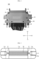
FIG. 3 is a front view illustrating the pin push inspection connector ofFIG. 2 . -
FIG. 4 is a view illustrating an example where a pin push inspection connector and a connector under test are fastened to each other according to an embodiment of the present disclosure. -
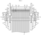
FIG. 5 is a cross-sectional view schematically illustrating main elements of a pin push inspection connector according to an embodiment of the present disclosure. -
FIGS. 6 and7 are views illustrating an example where a connection distance of a pin push inspection connector is adjusted according to an embodiment of the present disclosure. -
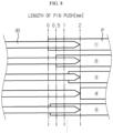
FIGS. 8 and9 are reference views for describing an example where a contact point between inspection pins and terminal pins of a connector under test is adjusted according to an embodiment of the present disclosure. - Hereinafter, preferred embodiments of the present disclosure will be described in detail with reference to the accompanying drawings. Prior to the description, it should be understood that the terms used in the specification and the appended claims should not be construed as limited to general and dictionary meanings, but interpreted based on the meanings and concepts corresponding to technical aspects of the present disclosure on the basis of the principle that the inventor is allowed to define terms appropriately for the best explanation. Also, the description proposed herein is just a preferable example for the purpose of illustrations only, not intended to limit the scope of the present disclosure, so it should be understood that other equivalents and modifications could be made thereto without departing from the scope of the present disclosure.
-
FIG. 1 is a view illustrating a connector under test that may be inspected by a pin push inspection connector according to an embodiment of the present disclosure.FIG. 2 is a photograph showing a pin push inspection connector according to an embodiment of the present disclosure. - A pin
push inspection connector 100 according to an embodiment of the present disclosure may be used as an inspection means that is directly connected to a connector undertest 200 to check whether all terminal pins P of the connector undertest 200 are pushed. - As shown in
FIG. 1 , the connector undertest 200 refers to a connector including a plurality of terminal pins P connected in a one-to-one manner to a plurality of cables and a housing into which the plurality of terminal pins P are inserted. The number and shape of terminal pins P in the connector undertest 200 may be determined according to characteristics of a product to be applied, and as shown inFIG. 2 , the pinpush inspection connector 100 may be connected to correspond to the connector undertest 200. - For example, the connector under
test 200 may be a sensing cable connector used in a battery module (pack) to transmit various data such as a voltage or a temperature to a battery management system (BMS). The pinpush inspection connector 100 according to the present embodiment may be connected in a plug-in manner to the sensing cable connector, and may include the same number ofinspection pins 30 as the terminal pins P of the sensing cable connector. When the terminal pins P of the sensing cable connector are of a female type, theinspection pins 30 may be of a male type, and in contrast, when the terminal pins P is of a male type, theinspection pins 30 may be of a female type. - Also, as described below in detail, because the pin
push inspection connector 100 is configured so that a contact point between theinspection pins 30 and the terminal pins P is variably adjustable before or after the pinpush inspection connector 100 is fastened to the connector undertest 200, the pinpush inspection connector 100 may be used to determine whether the terminal pins P are pushed backward from pre-determined positions and assembled (defective state) in a final function test after the assembly of the connector undertest 200. - Main elements of the pin
push inspection connector 100 according to an embodiment of the present disclosure will be described in detail with reference toFIGS. 3 through 7 . The pinpush inspection connector 100 may include afirst connector assembly 10, asecond connector assembly 20, and at least oneinspection pin 30, and may be provided as a complementary connector connectable to the connector undertest 200. - Referring to
FIGS. 4 and5 , thefirst connector assembly 10 may include afirst housing 11, aguide pin 12, alatch 13, and afirst fastening hole 14, may be connected to the connector undertest 200, and may be fixedly coupled to the connector undertest 200. - The
first housing 11 may include a firstmain body 11a of a central portion formed in a hollow structure and afirst wing body 11b integrally formed on both sides of the firstmain body 11a, and oneguide pin 12 and onelatch 13 may be provided on thefirst wing body 11b. - The
guide pin 12 may be fixedly coupled to thefirst wing body 11b and may extend in a first direction +Y from thefirst wing body 11b beyond the firstmain body 11a, and thelatch 13 may be formed in a substantially '┐ '-shaped bent structure and may rotate by a certain angle with respect to ahinge shaft 13a at a bent area in a direction intersecting the first direction +Y. - The connector under test 200 (see
FIG. 1 ) may include aconnection portion 210 inserted into a middle portion of thefirst housing 11 and alocking protrusion 220 provided on both sides with theconnection portion 210 therebetween. The terminal pins P may be located in theconnection portion 210, and aguide groove 230 into which theguide pin 12 may be inserted may be formed in thelocking protrusion 220. - In this configuration, a front portion of the first
main body 11a of thefirst housing 11 may be connected and fixed to the connector undertest 200 in the first direction +Y. In more detail, (seeFIG. 4 ), theconnection portion 210 of the connector undertest 200 may be inserted into the firstmain body 11a of thefirst housing 11, and theguide pin 12 may be inserted into theguide groove 230 of the connector undertest 200. In this case, a length of theguide pin 12 and a depth of theguide groove 230 of the connector undertest 200 may be determined so that, when theguide pin 12 reaches the end of theguide groove 230 of the connector undertest 200, theconnection portion 210 of the connector undertest 200 is no longer inserted into thefirst housing 11. - As described above, in a state where the
connection portion 210 of the connector undertest 200 is inserted into the firstmain body 11a of thefirst housing 11 and theguide pin 12 is inserted into theguide groove 230 of the connector undertest 200, when thelatch 13 is engaged with thelocking protrusion 220 of the connector undertest 200, thefirst connector assembly 10 does not move in the first direction +Y or a second direction -Y with respect to the connector undertest 200. - Also, as shown in
FIG. 5 , thefirst connector assembly 10 may include thefirst fastening hole 14 extending from a surface of a rear end portion of thefirst connector assembly 10 to a certain depth in the first direction +Y. The rear end portion of thefirst connector assembly 10 refers to a rear end portion of thefirst wing body 11b on both sides of thefirst housing 11 in the present embodiment. A thread may be provided on an inner circumferential surface of thefirst fastening hole 14, and a rod portion of alength adjusting bolt 22 may be screwed into thefirst fastening hole 14. - Referring back to
FIGS. 4 and5 , a front portion of thesecond connector assembly 20 may be connected in the first direction +Y to a rear portion of thefirst connector assembly 10. Also, a connection interval between thesecond connector assembly 20 and thefirst connector assembly 10 may be variably adjusted when necessary in the first direction +Y or a second direction -Y that is opposite to the first direction +Y. - The
second connector assembly 20 may include asecond housing 21, the inspection pins 30, thelength adjusting bolt 22, and alength fixing bolt 25. - The
second housing 21 may include a secondmain body 21a that may be partially inserted into the firstmain body 11a, and asecond wing body 21b integrally formed on both sides of the secondmain body 21a. - The inspection pins 30 may be connected to an extension line C for a continuity test, and may be provided in a state of being fixedly assembled to the second
main body 21a. - Each
inspection pin 30 may be fixed in a press-fit or snap-fit manner to apin holder 27 provided in the secondmain body 21a, and a front end portion of theinspection pin 30 may protrude from a front side of the secondmain body 21a. Also, the front end portion of theinspection pin 30 may be supported by apin support 16. Thepin support 16 is a plate-shaped body having a plurality of holes, and may be provided so that the front end portion of theinspection pin 30 is inserted into each hole. Thepin support 16 may be manufactured as a separate component, or may be integrally manufactured with the secondmain body 21a or the firstmain body 11a. - According to this configuration, because an interval, that is, a creepage distance, between the inspection pins 30 may be maintained constant by the
pin support 16 and the pin holder of the secondmain body 21a, the inspection pins 30 may be connected to the terminal pins P of the connector undertest 200 without being misaligned with the terminal pins P. - The
length adjusting bolt 22 may pass through a body of thesecond connector assembly 20 and may be screwed into thefirst fastening hole 14 of thefirst connector assembly 10 to a certain depth, and may be used as a means for variably adjusting a connection distance or a connection interval between thefirst connector assembly 10 and thesecond connector assembly 20. - In detail, in the present embodiment, the body of the
second connector assembly 20 refers to thesecond wing body 21b of thesecond housing 21. As shown inFIG. 5 , thesecond wing body 21b includes a through-hole 23. The through-hole 23 may be formed at a position corresponding to thefirst fastening hole 14 provided in thefirst wing body 1 1b in the first direction +Y, and thus, thelength adjusting bolt 22 may be screwed into thefirst fastening hole 14 of thefirst wing body 1 1b through the through-hole 23 of thesecond wing body 21b. - A pair of
length adjusting bolts 22 may be provided respectively on a left edge and a right edge of thesecond connector assembly 20. That is, thelength adjusting bolts 22 may be inserted into the through-hole 23 of thesecond wing body 21b on a left side and the through-hole 23 of thesecond wing body 21b on a right side. - In this case, because a thread is not formed on an inner circumferential surface of the through-
hole 23, the rod portion of thelength adjusting bolt 22 may be screwed only into thefirst fastening hole 14 of thefirst wing body 11b. - Accordingly, when the length adjusting bolt 212 is continuously turned clockwise, the
length adjusting bolt 22 may move forward in the first direction +Y, a head portion H may contact a surface of thesecond wing body 21b, and finally, thesecond wing body 21b is pushed by the head portion H to contact thefirst wing body 11b as shown inFIG. 6 . As such, when thefirst wing body 11b and thesecond wing body 21b contact each other, a connection interval between thefirst connector assembly 10 and thesecond connector assembly 20 is '0 mm'. - In this state, when the
length adjusting bolt 22 is slightly turned counterclockwise, thelength adjusting bolt 22 is released from thefirst fastening hole 14 and moves little by little in the second direction -Y. In this case, because the head portion H of the length adjusting bolt 212 is separated from the surface of thesecond wing body 21b in the second direction -Y, a connection interval between thefirst connector assembly 10 and thesecond connector assembly 20 may be increased. - Finally, when the
length adjusting bolt 22 is separated from thefirst fastening hole 14 of thefirst wing body 11b, thefirst connector assembly 10 and thesecond connector assembly 20 may be completely separated from each other with a slight force. - According to this configuration of the present disclosure, in a state where a connection interval between the
first connector assembly 10 and thesecond connector assembly 20 is `0 mm', for example, when positions of the inspection pins 30 are to be moved backward by 1 mm or 2 mm in the second direction -Y, a connection interval between thefirst connector assembly 10 and thesecond connector assembly 20 may be adjusted to be 1 mm or 2 mm by releasing thelength adjusting bolt 22 from thefirst fastening hole 14 little by little. - The
length fixing bolt 25 may be screwed into asecond fastening hole 26 passing through the body of thesecond connector assembly 20 in the first direction +Y to support the rear end portion of thefirst connector assembly 10, and may be used as a means for preventing a connection interval between thefirst connector assembly 10 and thesecond connector assembly 20 which is increased by thelength adjusting bolt 22 from being reduced again. - A pair of
length fixing bolts 25 may be provided between twolength adjusting bolts 22 and may be respectively inserted into thesecond fastening hole 26 perforated in thesecond wing body 21b on a left side and thesecond fastening hole 26 perforated in thesecond wing body 21b on a right side. - Because a thread is formed on an inner circumferential surface of the
second fastening hole 26, thelength fixing bolt 25 may be screwed into thesecond fastening hole 26. Thelength fixing bolt 25 may pass through thesecond fastening hole 26, and a front end portion of thelength fixing bolt 25 may support the rear end portion of thefirst connector assembly 10. - In more detail, the
second fastening hole 26 may be formed at a position corresponding to a rear end of theguide pin 12 located on thefirst wing body 11b, thelength fixing bolt 25 may be screwed into thesecond fastening hole 26, and the front end portion of thelength fixing bolt 25 may pass through thesecond fastening hole 26 to support the rear end of theguide pin 14. - For example, in a state as shown in
FIG. 6 , when thelength adjusting bolt 22 is released from thefirst fastening hole 14, thesecond connector assembly 20 is separated backward from thefirst connector assembly 10 by about 3 mm, and thelength fixing bolt 25 is left as it is, a connection interval between thefirst connector assembly 10 and thesecond connector assembly 20 is likely to be reduced again even with slight impact. Accordingly, in this case, when thelength fixing bolt 25 is turned clockwise to move forward in the first direction +Y, as shown inFIG. 7 , thelength fixing bolt 25 supports the rear end portion of thefirst connector assembly 10, that is, the rear end of theguide pin 12. Accordingly, even when there is impact, a connection interval between thefirst connector assembly 10 and thesecond connector assembly 20 which is increased by thelength adjusting bolt 22 is not reduced again. - As described above, the pin
push inspection connector 100 according to an embodiment of the present disclosure includes thefirst connector assembly 10 fixed to the connector undertest 200 and thesecond connector assembly 20 connected to thefirst connector assembly 10 by variably adjusting a connection interval. The inspection pins 30 to be connected to the terminal pins P of the connector undertest 200 are configured to move integrally with thesecond connector assembly 20 in the first direction +Y or the second direction -Y. - An example of use of the pin
push inspection connector 100 will be briefly described as follows. - For example, when inspection is performed on the connector under
test 200 assuming that a product in which a pin push of each terminal pin P is 2 mm or more is a defective product, a connection interval of the pinpush inspection connector 100 is set to `0 mm'. (It is assumed that when a connection interval between thefirst connector assembly 10 and thesecond connector assembly 20 is `0 mm', a connection length between theinspection pin 30 and the terminal pin P with no pin push is 2 mm). Next, the pinpush inspection connector 100 is connected to the connector undertest 200 and a continuity test is performed. - In this case, referring to
FIG. 8 , because theterminal pin P ④ and theinspection pin 30 corresponding thereto do not contact each other, current does not flow therethrough. Accordingly, it may be detected that theterminal pin P ④ is pushed by 2 mm or more and assembled. - In another example, when inspection is performed on the connector under
test 200 assuming that a product in which a pin push of each terminal pin P is 1 mm or more is a defective product, a connection interval of the pinpush inspection connector 100 is increased by 1 mm, the pinpush inspection connector 100 is connected to the connector undertest 200, and then a continuity test is performed. - In this case, referring to
FIG. 9 , because theterminal pin P ③ and theterminal pin P ④ do not contact the inspection pins 30 corresponding thereto, current does not flow therethrough. Accordingly, it may be detected that theterminal pin P ③ and theterminal pin P ④ are pushed by 1 mm or more and assembled. - In another example, the pin
push inspection connector 100 in which a connection interval is initially set to `0 mm' is connected to the connector undertest 200, and then, a continuity test is performed by sequentially increasing a connection interval by 0.5 mm. In this case, the terminal pins P having a pin push of 0.5 mm or less, 0.5 mm to 1.0 mm, 1.0 mm to 1.5 mm, 1.5 mm to 2.0 mm, and 2 mm or more may be detected. - As described above, according to a configuration and an operation of the pin
push inspection connector 100 according to the present disclosure, because a contact point with the terminal pins P of the connector undertest 200 may be variably adjusted, whether the terminal pins P of the connector undertest 200 are pushed may be easily determined even without performing existing X-ray imaging or Dino inspection. - While one or more embodiments of the present disclosure have been described with reference to the figures, the present disclosure is not limited to the above-described specific embodiments, and it will be understood by one of ordinary skill in the art that various changes in form and details may be made therein without departing from the scope as defined by the following claims.
- It will be understood by one of ordinary skill in the art that when terms indicating directions such as upper, lower, left, and right, are used, these terms are only for convenience of explanation and may vary according to a position of a target object, a position of an observer, etc.
Claims (10)
- A pin push inspection connector comprising:a first connector assembly having a front portion connected to a connector under test in a first direction and fixedly coupled to the connector under test; anda second connector assembly having a front portion connected to a rear portion of the first connector assembly in the first direction and provided so that a connection interval with respect to the first connector assembly is variably adjusted in the first direction or a second direction that is opposite to the first direction,wherein the second connector assembly comprises at least one inspection pin provided therein to be connected to at least one terminal pin provided in the connector under test.
- The pin push inspection connector according to claim 1, wherein the first connector assembly comprises a first fastening hole extending in the first direction from a rear end portion of the first connector assembly, and the second connector assembly comprises a length adjusting bolt passing through a body and screwed into the first fastening hole to a certain depth.
- The pin push inspection connector according to claim 2, wherein the second connector assembly further comprises a second fastening hole extending in the first direction and having a thread formed on an inner circumferential surface thereof, and a length fixing bolt screwed into the second fastening hole and provided to support the rear end portion of the first connector assembly.
- The pin push inspection connector according to claim 3, wherein a pair of length adjusting bolts are respectively provided on a left edge and a right edge of the second connector assembly.
- The pin push inspection connector according to claim 4, wherein a pair of length fixing bolts are provided between the pair of length adjusting bolts.
- The pin push inspection connector according to claim 1, wherein the at least one inspection pin is fixed in the second connector assembly to move integrally with the second connector assembly in the first direction or the second direction with respect to the first connector assembly.
- The pin push inspection connector according to claim 1, wherein the first connector assembly comprises a latch provided to be engaged with a locking protrusion provided on an outer portion of the connector under test.
- The pin push inspection connector according to claim 1, wherein the first connector assembly comprises a first housing comprising a first main body formed in a hollow structure and a first wing body integrally formed on both sides of the first main body, and a guide pin extending from the first wing body in the first direction beyond the first main body.
- The pin push inspection connector according to claim 3, wherein the first connector assembly comprises a first housing comprising a first main body formed in a hollow structure and a first wing body integrally formed on both sides of the first main body, and a guide pin extending from the first wing body in the first direction beyond the first main body,
wherein the length fixing bolt is provided so that a front end portion of the length fixing bolt supports a rear end of the guide pin located on the first wing body. - The pin push inspection connector according to claim 1, wherein the at least one inspection pin comprises a plurality of inspection pins, and is provided to be connected in a one-to-one plug-in manner to each terminal pin of the connector under test.
Applications Claiming Priority (2)
| Application Number | Priority Date | Filing Date | Title |
|---|---|---|---|
| KR1020210061289A KR102759065B1 (en) | 2021-05-12 | 2021-05-12 | Test connector for inspecting a connector with pins pushed back |
| PCT/KR2022/005491 WO2022239982A1 (en) | 2021-05-12 | 2022-04-15 | Pin pushing inspection connector |
Publications (3)
| Publication Number | Publication Date |
|---|---|
| EP4202455A1 true EP4202455A1 (en) | 2023-06-28 |
| EP4202455A4 EP4202455A4 (en) | 2024-04-10 |
| EP4202455B1 EP4202455B1 (en) | 2025-03-26 |
Family
ID=84028401
Family Applications (1)
| Application Number | Title | Priority Date | Filing Date |
|---|---|---|---|
| EP22807630.3A Active EP4202455B1 (en) | 2021-05-12 | 2022-04-15 | Pin push inspection connector |
Country Status (7)
| Country | Link |
|---|---|
| US (1) | US12625199B2 (en) |
| EP (1) | EP4202455B1 (en) |
| KR (1) | KR102759065B1 (en) |
| CN (1) | CN219997118U (en) |
| ES (1) | ES3022258T3 (en) |
| HU (1) | HUE070710T2 (en) |
| WO (1) | WO2022239982A1 (en) |
Family Cites Families (16)
| Publication number | Priority date | Publication date | Assignee | Title |
|---|---|---|---|---|
| DE3504606A1 (en) | 1985-02-11 | 1986-08-14 | Helmuth 4952 Porta Westfalica Kahl | DEVICE FOR CHECKING CABLES THAT HAVE PLUGS |
| US5030906A (en) * | 1990-01-18 | 1991-07-09 | Seagate Technology, Inc. | Electrical connecting apparatus |
| JP2563069Y2 (en) | 1991-11-20 | 1998-02-18 | 住友電装株式会社 | Connector terminal inspection device |
| JP3449033B2 (en) | 1995-04-28 | 2003-09-22 | 住友電装株式会社 | Connector inspection device |
| JPH11329614A (en) * | 1998-05-20 | 1999-11-30 | Sony Corp | Connector and inspection method using it |
| JP4921348B2 (en) * | 2007-12-28 | 2012-04-25 | 矢崎総業株式会社 | Conduction pin protection structure for continuity tester |
| KR200453172Y1 (en) | 2009-04-30 | 2011-04-15 | 양기선 | Connector inspection jig |
| KR20150110170A (en) * | 2014-03-24 | 2015-10-02 | 양기선 | Jig for testing a connector |
| US9692158B1 (en) * | 2015-05-15 | 2017-06-27 | Ardent Concepts, Inc. | Connector assembly for attaching cables to a planar electrical device |
| KR101574053B1 (en) * | 2015-07-10 | 2015-12-02 | 이창원 | Connector inspection device |
| KR101757834B1 (en) * | 2016-11-15 | 2017-07-14 | 이광우 | Instrumentation device for remote telemeter using power line communication |
| KR101890230B1 (en) * | 2017-02-20 | 2018-08-22 | 주식회사 경신 | Terminal test device of connector |
| JP6757369B2 (en) | 2018-07-06 | 2020-09-16 | 矢崎総業株式会社 | Continuity inspection jig and continuity pin inspection method |
| DE112018007897A5 (en) * | 2018-08-09 | 2021-04-29 | Lisa Dräxlmaier GmbH | TACTILE DETECTION OF A POSITION OF COMPONENTS OF A VEHICLE COMPONENT |
| KR102159271B1 (en) * | 2019-10-01 | 2020-09-23 | 홍성호 | Pin block socket device for connector checker |
| KR102526197B1 (en) | 2019-11-19 | 2023-04-27 | 아주대학교산학협력단 | Composition for diagnosis, preventing or treating bone diseases comprising cotl1 |
-
2021
- 2021-05-12 KR KR1020210061289A patent/KR102759065B1/en active Active
-
2022
- 2022-04-15 WO PCT/KR2022/005491 patent/WO2022239982A1/en not_active Ceased
- 2022-04-15 CN CN202290000189.2U patent/CN219997118U/en active Active
- 2022-04-15 ES ES22807630T patent/ES3022258T3/en active Active
- 2022-04-15 US US18/016,954 patent/US12625199B2/en active Active
- 2022-04-15 EP EP22807630.3A patent/EP4202455B1/en active Active
- 2022-04-15 HU HUE22807630A patent/HUE070710T2/en unknown
Also Published As
| Publication number | Publication date |
|---|---|
| WO2022239982A1 (en) | 2022-11-17 |
| EP4202455A4 (en) | 2024-04-10 |
| US12625199B2 (en) | 2026-05-12 |
| HUE070710T2 (en) | 2025-06-28 |
| KR20220153830A (en) | 2022-11-21 |
| CN219997118U (en) | 2023-11-10 |
| ES3022258T3 (en) | 2025-05-28 |
| KR102759065B1 (en) | 2025-01-22 |
| EP4202455B1 (en) | 2025-03-26 |
| US20230288499A1 (en) | 2023-09-14 |
Similar Documents
| Publication | Publication Date | Title |
|---|---|---|
| US8747146B2 (en) | Electrical connector having connector position assurance | |
| US8029323B2 (en) | High power electrical interface connection | |
| CA3023776A1 (en) | Plug contact set and method for testing the latching of the plug contact set | |
| EP3637561B1 (en) | Docking structure between vehicle body and battery | |
| CN106972301B (en) | Power Terminals with Compliant Pins for Power Connectors | |
| US9112294B2 (en) | Secondary locking mechanism for a plug | |
| US10454214B1 (en) | Vehicle lighting device and method | |
| CN114128058B (en) | Diagnostic plug-in connections, diagnostic heads and diagnostic systems | |
| US10164363B2 (en) | Double-sided card edge connector | |
| GB2547335A (en) | Self-powered mating detection connector | |
| CA3021384C (en) | Plug contact set and method for checking an engagement of the plug contact set | |
| US12625199B2 (en) | Pin push inspection connector | |
| US20230268703A1 (en) | Single Pass-Through Connector | |
| US9923303B2 (en) | Electrical connector with terminal centering system | |
| US10044142B1 (en) | Connector locking holder | |
| CN215116721U (en) | Drawer type equipment installation detection mechanism and rail vehicle that target in place | |
| US11296438B1 (en) | Electrical connector assembly having a terminal-less connection system | |
| JP2874493B2 (en) | Connector inspection device | |
| US20060121775A1 (en) | Connector plug | |
| US20060057862A1 (en) | Connecting device | |
| CN223139643U (en) | Guided pin header test connector and pin header test device | |
| CN216898731U (en) | Detection device for multiple pins of electric connector | |
| US9595798B2 (en) | VME P2 five row interface adapter assembly, system, and method | |
| US20250047015A1 (en) | Cable housing | |
| CN119110905A (en) | Tray for automatic wire harness processing machine and method for manufacturing wire harness |
Legal Events
| Date | Code | Title | Description |
|---|---|---|---|
| STAA | Information on the status of an ep patent application or granted ep patent |
Free format text: STATUS: THE INTERNATIONAL PUBLICATION HAS BEEN MADE |
|
| PUAI | Public reference made under article 153(3) epc to a published international application that has entered the european phase |
Free format text: ORIGINAL CODE: 0009012 |
|
| STAA | Information on the status of an ep patent application or granted ep patent |
Free format text: STATUS: REQUEST FOR EXAMINATION WAS MADE |
|
| 17P | Request for examination filed |
Effective date: 20230309 |
|
| AK | Designated contracting states |
Kind code of ref document: A1 Designated state(s): AL AT BE BG CH CY CZ DE DK EE ES FI FR GB GR HR HU IE IS IT LI LT LU LV MC MK MT NL NO PL PT RO RS SE SI SK SM TR |
|
| REG | Reference to a national code |
Ref country code: DE Ref legal event code: R079 Free format text: PREVIOUS MAIN CLASS: G01R0031280000 Ipc: G01R0031660000 Ref country code: DE Ref legal event code: R079 Ref document number: 602022012366 Country of ref document: DE Free format text: PREVIOUS MAIN CLASS: G01R0031280000 Ipc: G01R0031660000 |
|
| A4 | Supplementary search report drawn up and despatched |
Effective date: 20240307 |
|
| RIC1 | Information provided on ipc code assigned before grant |
Ipc: G01R 31/54 20200101ALN20240301BHEP Ipc: G01R 31/69 20200101ALI20240301BHEP Ipc: G01R 31/66 20200101AFI20240301BHEP |
|
| DAV | Request for validation of the european patent (deleted) | ||
| DAX | Request for extension of the european patent (deleted) | ||
| GRAP | Despatch of communication of intention to grant a patent |
Free format text: ORIGINAL CODE: EPIDOSNIGR1 |
|
| STAA | Information on the status of an ep patent application or granted ep patent |
Free format text: STATUS: GRANT OF PATENT IS INTENDED |
|
| RIC1 | Information provided on ipc code assigned before grant |
Ipc: G01R 31/54 20200101ALN20241002BHEP Ipc: G01R 31/69 20200101ALI20241002BHEP Ipc: G01R 31/66 20200101AFI20241002BHEP |
|
| INTG | Intention to grant announced |
Effective date: 20241018 |
|
| P01 | Opt-out of the competence of the unified patent court (upc) registered |
Free format text: CASE NUMBER: APP_59673/2024 Effective date: 20241104 |
|
| GRAS | Grant fee paid |
Free format text: ORIGINAL CODE: EPIDOSNIGR3 |
|
| GRAA | (expected) grant |
Free format text: ORIGINAL CODE: 0009210 |
|
| STAA | Information on the status of an ep patent application or granted ep patent |
Free format text: STATUS: THE PATENT HAS BEEN GRANTED |
|
| AK | Designated contracting states |
Kind code of ref document: B1 Designated state(s): AL AT BE BG CH CY CZ DE DK EE ES FI FR GB GR HR HU IE IS IT LI LT LU LV MC MK MT NL NO PL PT RO RS SE SI SK SM TR |
|
| REG | Reference to a national code |
Ref country code: GB Ref legal event code: FG4D |
|
| REG | Reference to a national code |
Ref country code: CH Ref legal event code: EP |
|
| REG | Reference to a national code |
Ref country code: DE Ref legal event code: R096 Ref document number: 602022012366 Country of ref document: DE |
|
| REG | Reference to a national code |
Ref country code: IE Ref legal event code: FG4D |
|
| REG | Reference to a national code |
Ref country code: ES Ref legal event code: FG2A Ref document number: 3022258 Country of ref document: ES Kind code of ref document: T3 Effective date: 20250528 |
|
| REG | Reference to a national code |
Ref country code: HU Ref legal event code: AG4A Ref document number: E070710 Country of ref document: HU |
|
| PG25 | Lapsed in a contracting state [announced via postgrant information from national office to epo] |
Ref country code: RS Free format text: LAPSE BECAUSE OF FAILURE TO SUBMIT A TRANSLATION OF THE DESCRIPTION OR TO PAY THE FEE WITHIN THE PRESCRIBED TIME-LIMIT Effective date: 20250626 |
|
| PG25 | Lapsed in a contracting state [announced via postgrant information from national office to epo] |
Ref country code: FI Free format text: LAPSE BECAUSE OF FAILURE TO SUBMIT A TRANSLATION OF THE DESCRIPTION OR TO PAY THE FEE WITHIN THE PRESCRIBED TIME-LIMIT Effective date: 20250326 |
|
| PGFP | Annual fee paid to national office [announced via postgrant information from national office to epo] |
Ref country code: DE Payment date: 20250407 Year of fee payment: 4 |
|
| PGFP | Annual fee paid to national office [announced via postgrant information from national office to epo] |
Ref country code: ES Payment date: 20250516 Year of fee payment: 4 |
|
| REG | Reference to a national code |
Ref country code: LT Ref legal event code: MG9D |
|
| PG25 | Lapsed in a contracting state [announced via postgrant information from national office to epo] |
Ref country code: NO Free format text: LAPSE BECAUSE OF FAILURE TO SUBMIT A TRANSLATION OF THE DESCRIPTION OR TO PAY THE FEE WITHIN THE PRESCRIBED TIME-LIMIT Effective date: 20250626 |
|
| PGFP | Annual fee paid to national office [announced via postgrant information from national office to epo] |
Ref country code: HU Payment date: 20250526 Year of fee payment: 4 |
|
| PG25 | Lapsed in a contracting state [announced via postgrant information from national office to epo] |
Ref country code: HR Free format text: LAPSE BECAUSE OF FAILURE TO SUBMIT A TRANSLATION OF THE DESCRIPTION OR TO PAY THE FEE WITHIN THE PRESCRIBED TIME-LIMIT Effective date: 20250326 |
|
| PG25 | Lapsed in a contracting state [announced via postgrant information from national office to epo] |
Ref country code: LV Free format text: LAPSE BECAUSE OF FAILURE TO SUBMIT A TRANSLATION OF THE DESCRIPTION OR TO PAY THE FEE WITHIN THE PRESCRIBED TIME-LIMIT Effective date: 20250326 |
|
| PG25 | Lapsed in a contracting state [announced via postgrant information from national office to epo] |
Ref country code: GR Free format text: LAPSE BECAUSE OF FAILURE TO SUBMIT A TRANSLATION OF THE DESCRIPTION OR TO PAY THE FEE WITHIN THE PRESCRIBED TIME-LIMIT Effective date: 20250627 Ref country code: BG Free format text: LAPSE BECAUSE OF FAILURE TO SUBMIT A TRANSLATION OF THE DESCRIPTION OR TO PAY THE FEE WITHIN THE PRESCRIBED TIME-LIMIT Effective date: 20250326 |
|
| PGFP | Annual fee paid to national office [announced via postgrant information from national office to epo] |
Ref country code: AT Payment date: 20250721 Year of fee payment: 4 |
|
| REG | Reference to a national code |
Ref country code: NL Ref legal event code: MP Effective date: 20250326 |
|
| PG25 | Lapsed in a contracting state [announced via postgrant information from national office to epo] |
Ref country code: NL Free format text: LAPSE BECAUSE OF FAILURE TO SUBMIT A TRANSLATION OF THE DESCRIPTION OR TO PAY THE FEE WITHIN THE PRESCRIBED TIME-LIMIT Effective date: 20250326 |
|
| PG25 | Lapsed in a contracting state [announced via postgrant information from national office to epo] |
Ref country code: SE Free format text: LAPSE BECAUSE OF FAILURE TO SUBMIT A TRANSLATION OF THE DESCRIPTION OR TO PAY THE FEE WITHIN THE PRESCRIBED TIME-LIMIT Effective date: 20250326 |
|
| REG | Reference to a national code |
Ref country code: AT Ref legal event code: MK05 Ref document number: 1779441 Country of ref document: AT Kind code of ref document: T Effective date: 20250326 |
|
| PG25 | Lapsed in a contracting state [announced via postgrant information from national office to epo] |
Ref country code: SM Free format text: LAPSE BECAUSE OF FAILURE TO SUBMIT A TRANSLATION OF THE DESCRIPTION OR TO PAY THE FEE WITHIN THE PRESCRIBED TIME-LIMIT Effective date: 20250326 |
|
| PG25 | Lapsed in a contracting state [announced via postgrant information from national office to epo] |
Ref country code: PT Free format text: LAPSE BECAUSE OF FAILURE TO SUBMIT A TRANSLATION OF THE DESCRIPTION OR TO PAY THE FEE WITHIN THE PRESCRIBED TIME-LIMIT Effective date: 20250728 |
|
| PG25 | Lapsed in a contracting state [announced via postgrant information from national office to epo] |
Ref country code: PL Free format text: LAPSE BECAUSE OF FAILURE TO SUBMIT A TRANSLATION OF THE DESCRIPTION OR TO PAY THE FEE WITHIN THE PRESCRIBED TIME-LIMIT Effective date: 20250326 Ref country code: IT Free format text: LAPSE BECAUSE OF FAILURE TO SUBMIT A TRANSLATION OF THE DESCRIPTION OR TO PAY THE FEE WITHIN THE PRESCRIBED TIME-LIMIT Effective date: 20250326 |
|
| PG25 | Lapsed in a contracting state [announced via postgrant information from national office to epo] |
Ref country code: AT Free format text: LAPSE BECAUSE OF FAILURE TO SUBMIT A TRANSLATION OF THE DESCRIPTION OR TO PAY THE FEE WITHIN THE PRESCRIBED TIME-LIMIT Effective date: 20250326 |
|
| PG25 | Lapsed in a contracting state [announced via postgrant information from national office to epo] |
Ref country code: EE Free format text: LAPSE BECAUSE OF FAILURE TO SUBMIT A TRANSLATION OF THE DESCRIPTION OR TO PAY THE FEE WITHIN THE PRESCRIBED TIME-LIMIT Effective date: 20250326 |
|
| PG25 | Lapsed in a contracting state [announced via postgrant information from national office to epo] |
Ref country code: RO Free format text: LAPSE BECAUSE OF FAILURE TO SUBMIT A TRANSLATION OF THE DESCRIPTION OR TO PAY THE FEE WITHIN THE PRESCRIBED TIME-LIMIT Effective date: 20250326 |
|
| PG25 | Lapsed in a contracting state [announced via postgrant information from national office to epo] |
Ref country code: SK Free format text: LAPSE BECAUSE OF FAILURE TO SUBMIT A TRANSLATION OF THE DESCRIPTION OR TO PAY THE FEE WITHIN THE PRESCRIBED TIME-LIMIT Effective date: 20250326 |
|
| PG25 | Lapsed in a contracting state [announced via postgrant information from national office to epo] |
Ref country code: IS Free format text: LAPSE BECAUSE OF FAILURE TO SUBMIT A TRANSLATION OF THE DESCRIPTION OR TO PAY THE FEE WITHIN THE PRESCRIBED TIME-LIMIT Effective date: 20250726 |
|
| REG | Reference to a national code |
Ref country code: CH Ref legal event code: H13 Free format text: ST27 STATUS EVENT CODE: U-0-0-H10-H13 (AS PROVIDED BY THE NATIONAL OFFICE) Effective date: 20251125 |
|
| PG25 | Lapsed in a contracting state [announced via postgrant information from national office to epo] |
Ref country code: LU Free format text: LAPSE BECAUSE OF NON-PAYMENT OF DUE FEES Effective date: 20250415 |
|
| PG25 | Lapsed in a contracting state [announced via postgrant information from national office to epo] |
Ref country code: MC Free format text: LAPSE BECAUSE OF FAILURE TO SUBMIT A TRANSLATION OF THE DESCRIPTION OR TO PAY THE FEE WITHIN THE PRESCRIBED TIME-LIMIT Effective date: 20250326 |
|
| REG | Reference to a national code |
Ref country code: DE Ref legal event code: R097 Ref document number: 602022012366 Country of ref document: DE |
|
| PG25 | Lapsed in a contracting state [announced via postgrant information from national office to epo] |
Ref country code: DK Free format text: LAPSE BECAUSE OF FAILURE TO SUBMIT A TRANSLATION OF THE DESCRIPTION OR TO PAY THE FEE WITHIN THE PRESCRIBED TIME-LIMIT Effective date: 20250326 |
|
| PG25 | Lapsed in a contracting state [announced via postgrant information from national office to epo] |
Ref country code: CH Free format text: LAPSE BECAUSE OF NON-PAYMENT OF DUE FEES Effective date: 20250430 |
|
| PG25 | Lapsed in a contracting state [announced via postgrant information from national office to epo] |
Ref country code: CZ Free format text: LAPSE BECAUSE OF FAILURE TO SUBMIT A TRANSLATION OF THE DESCRIPTION OR TO PAY THE FEE WITHIN THE PRESCRIBED TIME-LIMIT Effective date: 20250326 |
|
| PLBE | No opposition filed within time limit |
Free format text: ORIGINAL CODE: 0009261 |
|
| STAA | Information on the status of an ep patent application or granted ep patent |
Free format text: STATUS: NO OPPOSITION FILED WITHIN TIME LIMIT |
|
| REG | Reference to a national code |
Ref country code: CH Ref legal event code: L10 Free format text: ST27 STATUS EVENT CODE: U-0-0-L10-L00 (AS PROVIDED BY THE NATIONAL OFFICE) Effective date: 20260211 |
|
| 26N | No opposition filed |
Effective date: 20260105 |
|
| PGFP | Annual fee paid to national office [announced via postgrant information from national office to epo] |
Ref country code: GB Payment date: 20260324 Year of fee payment: 5 |
|
| PG25 | Lapsed in a contracting state [announced via postgrant information from national office to epo] |
Ref country code: IE Free format text: LAPSE BECAUSE OF NON-PAYMENT OF DUE FEES Effective date: 20250415 |
|
| PGFP | Annual fee paid to national office [announced via postgrant information from national office to epo] |
Ref country code: BE Payment date: 20260323 Year of fee payment: 5 |
|
| PGFP | Annual fee paid to national office [announced via postgrant information from national office to epo] |
Ref country code: FR Payment date: 20260323 Year of fee payment: 5 |