EP4202453A1 - Laser-induced discharging method and system for generating long-range controllable high-voltage discharge - Google Patents
Laser-induced discharging method and system for generating long-range controllable high-voltage discharge Download PDFInfo
- Publication number
- EP4202453A1 EP4202453A1 EP22859567.4A EP22859567A EP4202453A1 EP 4202453 A1 EP4202453 A1 EP 4202453A1 EP 22859567 A EP22859567 A EP 22859567A EP 4202453 A1 EP4202453 A1 EP 4202453A1
- Authority
- EP
- European Patent Office
- Prior art keywords
- laser
- discharge
- convex lens
- rod electrode
- control system
- Prior art date
- Legal status (The legal status is an assumption and is not a legal conclusion. Google has not performed a legal analysis and makes no representation as to the accuracy of the status listed.)
- Pending
Links
Images
Classifications
-
- H—ELECTRICITY
- H05—ELECTRIC TECHNIQUES NOT OTHERWISE PROVIDED FOR
- H05H—PLASMA TECHNIQUE; PRODUCTION OF ACCELERATED ELECTRICALLY-CHARGED PARTICLES OR OF NEUTRONS; PRODUCTION OR ACCELERATION OF NEUTRAL MOLECULAR OR ATOMIC BEAMS
- H05H1/00—Generating plasma; Handling plasma
- H05H1/24—Generating plasma
-
- G—PHYSICS
- G01—MEASURING; TESTING
- G01R—MEASURING ELECTRIC VARIABLES; MEASURING MAGNETIC VARIABLES
- G01R31/00—Arrangements for testing electric properties; Arrangements for locating electric faults; Arrangements for electrical testing characterised by what is being tested not provided for elsewhere
- G01R31/12—Testing dielectric strength or breakdown voltage ; Testing or monitoring effectiveness or level of insulation, e.g. of a cable or of an apparatus, for example using partial discharge measurements; Electrostatic testing
-
- G—PHYSICS
- G01—MEASURING; TESTING
- G01R—MEASURING ELECTRIC VARIABLES; MEASURING MAGNETIC VARIABLES
- G01R31/00—Arrangements for testing electric properties; Arrangements for locating electric faults; Arrangements for electrical testing characterised by what is being tested not provided for elsewhere
- G01R31/12—Testing dielectric strength or breakdown voltage ; Testing or monitoring effectiveness or level of insulation, e.g. of a cable or of an apparatus, for example using partial discharge measurements; Electrostatic testing
- G01R31/16—Construction of testing vessels; Electrodes therefor
-
- H—ELECTRICITY
- H05—ELECTRIC TECHNIQUES NOT OTHERWISE PROVIDED FOR
- H05H—PLASMA TECHNIQUE; PRODUCTION OF ACCELERATED ELECTRICALLY-CHARGED PARTICLES OR OF NEUTRONS; PRODUCTION OR ACCELERATION OF NEUTRAL MOLECULAR OR ATOMIC BEAMS
- H05H1/00—Generating plasma; Handling plasma
- H05H1/24—Generating plasma
- H05H1/48—Generating plasma using an arc
Definitions
- the present disclosure relates to the technical field of high voltage applications, and specifically, to a laser induced discharge method and system for generating a long-distance controllable high-voltage discharge.
- laser induced discharge is widely used in precision machining, high-voltage switch synchronization, and other fields, and has potential application value in laser induced lightning, long-distance detection, and other fields.
- a nanosecond pulse laser is maturely applied in the field of the laser induced discharge.
- electron avalanches are generated in air to form breakdown sparks to shield laser at a back edge of a pulse. As a result, a continuous plasma channel cannot be formed.
- a dipulse-based laser induced gap breakdown switching device disclosed in the application with the application number of CN201910001377.1 includes a laser-triggered switching apparatus based on optical fiber control, a signal coupling apparatus, and a control and detection apparatus.
- the laser-triggered switching apparatus based on optical fiber control includes a box body, a first plano-convex lens, a hollow electrode, a plate electrode, and a first optical fiber connector.
- the control and detection apparatus includes a dipulse nanosecond laser and a programmable pulse delay generator.
- the dipulse nanosecond laser generates first pulse laser and main pulse laser, and focuses them on the plate electrode.
- the programmable pulse delay generator adjusts a time interval of the first pulse laser and the main pulse laser.
- Weaker first pulse laser enters the box body through an optical fiber focuser and induces generation of an initial plasma. Subsequently, laser energy of the main pulse is high when the main pulse secondarily bombards the plate electrode, inducing generation of a high-temperature and high-density main plasma.
- the switching device can avoid the switch jitter and the trigger delay to some extent, but it still cannot realize the long-distance guiding of the high-voltage discharge.
- a high-power ultrashort pulse laser produces a nonlinear optical effect during propagation in the medium, overcomes shortcomings such as discontinuity and a short length of a plasma channel of the nanosecond laser by using a dynamic balance between a Kerr self-focusing effect and a plasma defocusing effect, so as to perform ionization in the air to produce a continuous and long plasma channel, thereby having a good application prospect in the fields of guiding the long-distance high-voltage discharge, the long-distance detection, and the like.
- the long plasma channel Based on an ionization and propagation mechanism of the ultrashort pulse laser in the air, the long plasma channel has its unique distribution characteristics of electrical properties in time and space, resulting in different impacts of laser parameters, discharge system parameters, and temporal and spatial coordination between laser generated by a laser system and a discharge generated by a discharge system on trigger and guiding characteristics of the high-voltage discharge.
- a laser induced discharge system with stable trigger and guiding characteristics is needed to generate a long-distance controllable high-voltage discharge and promote a development of the laser induced lightning, the long-distance detection, and other fields.
- a technical problem to be resolved in the present disclosure is to provide a long-distance controllable high-voltage discharge system with stable trigger and guiding characteristics.
- the laser induced discharge system in the present disclosure invention can generate a meter-level discharge that is from the tip of the rod electrode and develops along a laser path when the laser reaches the rod electrode, and realize a long-distance controllable high-voltage discharge with controllable start discharge time and a controllable discharge path.
- the laser source is an ultrashort pulse laser that is generated based on a titanium doped sapphire gain medium and a chirped pulse amplification technology and has a repetition frequency of 10 Hz, a wavelength of 800 nm, MJ-level energy, and an fs-level or ps-level pulse width.
- a geometric focal length of the convex lens is 10 m.
- the discharge module includes the impulse voltage generator and the rod electrode, the impulse voltage generator is capable of generating a negative switching impulse voltage with a peak value of equal to or greater than 1.6 MV, a rod-plate gap of the rod electrode is greater than or equal to 2 m, a curvature radius of the tip of the rod electrode is 10 mm, the rod electrode is connected to a high voltage, and a plate electrode is grounded.
- control system includes a photoelectric detector, an oscilloscope, a delay controller, and an electro-optic/photoelectric conversion module
- the photoelectric detector is connected to the oscilloscope
- the oscilloscope is connected to the delay controller
- the delay controller is connected to the electro-optic/photoelectric conversion module
- the electro-optic/photoelectric conversion module is connected to the discharge module.
- the present disclosure further provides a laser induced discharge method for generating a long-distance controllable high-voltage discharge, including following steps:
- the laser source is an ultrashort pulse laser that is generated based on a titanium doped sapphire gain medium and a chirped pulse amplification technology and has a repetition frequency of 10 Hz, a wavelength of 800 nm, MJ-level energy, and an fs-level or ps-level pulse width.
- a geometric focal length of the convex lens is 10 m.
- the discharge module includes the impulse voltage generator and the rod electrode, the impulse voltage generator is capable of generating a negative switching impulse voltage with a peak value of equal to or greater than 1.6 MV, a rod-plate gap of the rod electrode is greater than or equal to 2 m, a curvature radius of the tip of the rod electrode is 10 mm, the rod electrode is connected to a high voltage, and a plate electrode is grounded.
- control system includes a photoelectric detector, an oscilloscope, a delay controller, and an electro-optic/photoelectric conversion module
- the photoelectric detector is connected to the oscilloscope
- the oscilloscope is connected to the delay controller
- the delay controller is connected to the electro-optic/photoelectric conversion module
- the electro-optic/photoelectric conversion module is connected to the discharge module.
- the high-power ultrashort pulse laser source can perform ionization to form a 5 m long plasma channel in air after passing through the guiding optical path, which is much longer than a plasma channel that can be formed in the air by a nanosecond pulse laser in an existing laser induced discharge system.
- a longest-distance discharge starting from the tip of the rod electrode can be realized, that is, optimal spatial coordination between the laser system and the discharge module is achieved.
- the delay is set for the delay controller, which achieves optimal temporal coordination between the laser system and the discharge module.
- a probability of a laser induced discharge can be equal to or greater than 99%, and a path of the laser induced discharge can reach a meter level, which is of great significance to the development of laser guided long-distance high-voltage discharge, laser induced lightning, long-distance laser detection, and other technologies.
- the embodiments provide a laser induced discharge system for generating a long-distance controllable high-voltage discharge, including a laser source, a guiding optical path, a discharge module, and a control system.
- the laser source in the embodiments is a high-power ultrashort pulse laser source, namely, an ultrashort pulse laser that is generated based on a titanium doped sapphire gain medium and a chirped pulse amplification technology and has a repetition frequency of 10 Hz, a wavelength of 800 nm, MJ-level energy, and an fs-level or ps-level pulse width.
- a nonlinear optical effect is generated when high-power ultrashort pulse laser is propagated in a medium, and a continuous long plasma channel can be produced through ionization in air based on a dynamic balance between a Kerr self-focusing effect and a plasma defocusing effect.
- the discharge module includes an impulse voltage generator and a rod electrode.
- the impulse voltage generator is capable of generating a negative switching impulse voltage with a peak value of equal to or greater than 1.6 MV, a rod-plate gap of the rod electrode is greater than or equal to 2 m, a curvature radius of a tip of the rod electrode is 10 mm, the rod electrode is connected to a high voltage, and a plate electrode is grounded.
- the guiding optical path includes a plurality of reflectors and a convex lens.
- laser emitted by the laser source enters the convex lens after being reflected by the reflectors, and then is incident into the discharge module from the convex lens.
- the horizontally emitted laser is horizontally reflected into the convex lens 5 by using four reflectors 1, 2, 3, and 4 sequentially, and then is incident into the discharge module through the convex lens 5.
- a geometric focal length of the convex lens 5 is 10 m.
- the control system includes a photoelectric detector, an oscilloscope, a delay controller, and an electro-optic/photoelectric conversion module.
- the photoelectric detector is connected to the oscilloscope, the oscilloscope is connected to the delay controller, the delay controller (a DG535 delay controller is adopted in the embodiments) is connected to the electro-optic/photoelectric conversion module, and the electro-optic/photoelectric conversion module is connected to the discharge module.
- the photoelectric detector detects an output signal of the laser source for the oscilloscope to read. Rising edge trigger is set for the oscilloscope to output a trigger signal to the DG535 delay controller when the signal is read.
- a delay between the signal output by the oscilloscope and a new trigger signal is set for the DG535 delay controller, and the new trigger signal is transmitted to an electro-optic conversion module of the electro-optic/photoelectric conversion module.
- the new trigger signal is transmitted to an electro-optic conversion module of the electro-optic/photoelectric conversion module.
- a final electrical signal is transmitted to the impulse voltage generator.
- the electro-optic conversion module is configured to convert a TTL signal into the optical signal
- the photoelectric conversion module is configured to convert the optical signal into a 10 kV pulse signal and trigger the first-level sphere gap of the impulse voltage generator.
- the laser source is turned on to output the laser at the repetition frequency of 10 Hz.
- An output first laser signal is detected by the photoelectric detector and becomes a trigger pulse of the first-level sphere gap of the impulse voltage generator after passing through the control system.
- a delay setting of the control system enables a second signal of a laser system to temporally coincide with a voltage pulse loaded on the rod electrode by the impulse voltage generator, thus generating a laser induced discharge.
- the guiding optical path guarantees spatial coordination between the laser system and the discharge module, such that the generated laser induced discharge is a long-distance high-voltage discharge along a laser path.
- the empirical formula gives optimal spatial coordination between the laser system and the discharge module, which can realize a longest-distance discharge starting from the tip of the rod electrode.
- the trigger delay ⁇ t is set to 1ms- t d - t f for the DG535 delay controller, which achieves optimal temporal coordination between the laser system and the discharge module.
- a probability of the laser induced discharge (laser-triggered discharge developing along the laser path) can be equal to or greater than 99%, and a path of the laser induced discharge can reach a meter level, which is of great significance to the development of laser guided long-distance high-voltage discharge, laser induced lightning, long-distance laser detection, and other technologies.
- a combination relationship and a position relationship of the reflectors in the guiding optical path and the geometric focal length of the convex lens are determined based on positions of the laser source and the rod electrode to meet optimal spatial coordination between the laser source and the discharge module, in other words, a distance between the convex lens and the rod electrode.
- the above spatial distance and delay should meet following conditions: When the first laser signal output by the laser source is detected by the photoelectric detector and becomes the trigger pulse of the first-level sphere gap of the impulse voltage generator after passing through the control system, the delay setting of the control system enables the second signal of the laser system to temporally coincide with the voltage pulse loaded on the rod electrode by the impulse voltage generator, thus generating the laser induced discharge.
- the guiding optical path guarantees the spatial coordination between the laser system and the discharge module, such that the generated laser induced discharge is the long-distance high-voltage discharge along the laser path.
- the embodiments further provide a laser induced discharge method for generating a long-distance controllable high-voltage discharge, including following steps.
- Step 1 Build a discharge system, where the discharge system includes a laser system, a guiding optical path, a discharge module, and a control system; and the laser source reaches the discharge module through the guiding optical path.
- the control system includes a photoelectric detector, an oscilloscope, a delay controller, and an electro-optic/photoelectric conversion module.
- the photoelectric detector is connected to the oscilloscope
- the oscilloscope is connected to the delay controller
- the delay controller is connected to the electro-optic/photoelectric conversion module
- the electro-optic/photoelectric conversion module is connected to the discharge module.
- Step 2 Start the laser source, detect, by the photoelectric detector, a first laser output signal of the laser source for the oscilloscope to read, output, by the oscilloscope, a trigger signal to the delay controller when reading the signal, set a delay between the signal output by the oscilloscope and a new trigger signal for the delay controller, and transmit the new trigger signal to an electro-optic conversion module, and transmit a final electrical signal to the impulse voltage generator after an optical signal is transmitted to a photoelectric conversion module by using an optical fiber.
- Step 3 Trigger, by the impulse voltage generator, a discharge after receiving the trigger signal, where a delay setting of the control system enables a second signal of a laser system to temporally coincide with a voltage pulse loaded on the rod electrode by the impulse voltage generator, such that the discharge develops along a laser path.
- the laser source is an ultrashort pulse laser that is generated based on a titanium doped sapphire gain medium and a chirped pulse amplification technology and has a repetition frequency of 10 Hz, a wavelength of 800 nm, MJ-level energy, and an fs-level or ps-level pulse width.
- the guiding optical path includes a plurality of reflectors and a convex lens.
- laser emitted by the laser source enters the convex lens after being reflected by the reflectors, and then is incident into the discharge module from the convex lens.
- a geometric focal length of the convex lens is 10 m.
- the discharge module includes the impulse voltage generator and the rod electrode.
- the impulse voltage generator is capable of generating a negative switching impulse voltage with a peak value of equal to or greater than 1.6 MV, a rod-plate gap of the rod electrode is greater than or equal to 2 m, a curvature radius of a tip of the rod electrode is 10 mm, the rod electrode is connected to a high voltage, and a plate electrode is grounded.
- the photoelectric detector detects the output signal of the laser source for the oscilloscope to read. Rising edge trigger is set for the oscilloscope to output the trigger signal to the DG535 delay controller when the signal is read. The delay between the signal output by the oscilloscope and the new trigger signal is set for the DG535 delay controller, and the new trigger signal is transmitted to the electro-optic conversion module of the electro-optic/photoelectric conversion module. After the optical signal is transmitted to the photoelectric conversion module of the electro-optic/photoelectric conversion module by using the optical fiber, the final electrical signal is transmitted to the impulse voltage generator.
- the electro-optic conversion module is configured to convert a TTL signal into the optical signal, and the photoelectric conversion module is configured to convert the optical signal into a 10 kV pulse signal and trigger the first-level sphere gap of the impulse voltage generator.
- the laser source is turned on to output the laser at the repetition frequency of 10 Hz.
- An output first laser signal is detected by the photoelectric detector and becomes a trigger pulse of the first-level sphere gap of the impulse voltage generator after passing through the control system.
- the delay setting of the control system enables the second signal of the laser system to temporally coincide with the voltage pulse loaded on the rod electrode by the impulse voltage generator, thus generating a laser induced discharge.
- the guiding optical path guarantees spatial coordination between the laser system and the discharge module, such that the generated laser induced discharge is a long-distance high-voltage discharge along a laser path.
- a longest-distance discharge starting from the tip of the rod electrode can be realized based on the distance between the laser emitting end of the guiding optical path and the tip of the rod electrode of the discharge module, in other words, the above distance calculation formula gives optimal spatial coordination between the laser system and the discharge module.
- the trigger delay ⁇ t is set to 1ms- t d - t f for the DG535 delay controller, which achieves optimal temporal coordination between the laser system and the discharge module.
- a probability of the laser induced discharge can be equal to or greater than 99%, and a path of the laser induced discharge can reach a meter level, which is of great significance to the development of laser guided long-distance high-voltage discharge, laser induced lightning, long-distance laser detection, and other technologies.
- a combination relationship and a position relationship of the reflectors in the guiding optical path and the geometric focal length of the convex lens are determined based on positions of the laser source and the rod electrode to meet optimal spatial coordination between the laser source and the discharge module, in other words, a distance between an emitting end of the convex lens and the rod electrode.
- the above spatial distance and delay should meet following conditions: When the first laser signal output by the laser source is detected by the photoelectric detector and becomes the trigger pulse of the first-level sphere gap of the impulse voltage generator after passing through the control system, the delay setting of the control system enables the second signal of the laser system to temporally coincide with the voltage pulse loaded on the rod electrode by the impulse voltage generator, thus generating the laser induced discharge.
- the guiding optical path guarantees the spatial coordination between the laser system and the discharge module, such that the generated laser induced discharge is the long-distance high-voltage discharge along the laser path.
Landscapes
- Physics & Mathematics (AREA)
- Engineering & Computer Science (AREA)
- Plasma & Fusion (AREA)
- General Physics & Mathematics (AREA)
- Spectroscopy & Molecular Physics (AREA)
- Lasers (AREA)
Abstract
Description
- The present disclosure relates to the technical field of high voltage applications, and specifically, to a laser induced discharge method and system for generating a long-distance controllable high-voltage discharge.
- As a technology that uses controllability of laser and large energy of a discharge to achieve photoelectric energy coupling, laser induced discharge is widely used in precision machining, high-voltage switch synchronization, and other fields, and has potential application value in laser induced lightning, long-distance detection, and other fields. At present, a nanosecond pulse laser is maturely applied in the field of the laser induced discharge. However, due to characteristics of a long pulse width and high energy of the nanosecond pulse laser, when laser is propagated in an air medium, electron avalanches are generated in air to form breakdown sparks to shield laser at a back edge of a pulse. As a result, a continuous plasma channel cannot be formed. Energy of the laser also attenuates rapidly during the propagation due to air breakdown, which severely limits a length of the plasma channel. As a result, long-distance guiding of a high-voltage discharge cannot be realized, thereby limiting the development of the laser induced discharge in the laser induced lightning, the long-distance detection, and other fields.
- For example, a dipulse-based laser induced gap breakdown switching device disclosed in the application with the application number of
CN201910001377.1 - In recent years, an ultrashort pulse laser technology has developed rapidly. Compared with a high-energy nanosecond laser used before the ultrashort pulse laser technology, a high-power ultrashort pulse laser produces a nonlinear optical effect during propagation in the medium, overcomes shortcomings such as discontinuity and a short length of a plasma channel of the nanosecond laser by using a dynamic balance between a Kerr self-focusing effect and a plasma defocusing effect, so as to perform ionization in the air to produce a continuous and long plasma channel, thereby having a good application prospect in the fields of guiding the long-distance high-voltage discharge, the long-distance detection, and the like. Based on an ionization and propagation mechanism of the ultrashort pulse laser in the air, the long plasma channel has its unique distribution characteristics of electrical properties in time and space, resulting in different impacts of laser parameters, discharge system parameters, and temporal and spatial coordination between laser generated by a laser system and a discharge generated by a discharge system on trigger and guiding characteristics of the high-voltage discharge. To sum up, a laser induced discharge system with stable trigger and guiding characteristics is needed to generate a long-distance controllable high-voltage discharge and promote a development of the laser induced lightning, the long-distance detection, and other fields.
- A technical problem to be resolved in the present disclosure is to provide a long-distance controllable high-voltage discharge system with stable trigger and guiding characteristics.
- The present disclosure resolves the above problem by using following technical solutions:
- A laser induced discharge system for generating a long-distance controllable high-voltage discharge includes a laser system, a guiding optical path, a discharge module, and a control system, where a laser source of the laser system is a high-power ultrashort pulse laser source;
- the control system receives a laser signal of the laser system, and starts the discharge module based on the laser signal; and the control system is provided with a trigger delay;
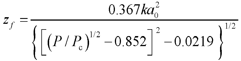
- the guiding optical path includes a plurality of reflectors and a convex lens; laser reaches the convex lens after being reflected by the reflectors, and then reaches the discharge module through the convex lens; and a distance between the convex lens and a tip of a rod electrode of the discharge module is calculated according to following formulae:


- where k represents a wave number, a 0 represents a spot radius, P represents a laser peak power, P c represents a critical power of the laser when the laser generates ionization and makes laser filament, f represents a focal length of the convex lens, and zf represents a self-focusing effect of an incident gap of the laser; and
- the trigger delay δt is equal to 1 ms-t d-t f, where t d represents time from triggering of a first-level sphere gap of an impulse voltage generator in the discharge module to loading of a switching impulse voltage waveform to the rod electrode, and t f represents time of a rising edge of the impulse voltage waveform.
- The laser induced discharge system in the present disclosure invention can generate a meter-level discharge that is from the tip of the rod electrode and develops along a laser path when the laser reaches the rod electrode, and realize a long-distance controllable high-voltage discharge with controllable start discharge time and a controllable discharge path.
- Further, the laser source is an ultrashort pulse laser that is generated based on a titanium doped sapphire gain medium and a chirped pulse amplification technology and has a repetition frequency of 10 Hz, a wavelength of 800 nm, MJ-level energy, and an fs-level or ps-level pulse width.
- Further, a geometric focal length of the convex lens is 10 m.
- Further, the discharge module includes the impulse voltage generator and the rod electrode, the impulse voltage generator is capable of generating a negative switching impulse voltage with a peak value of equal to or greater than 1.6 MV, a rod-plate gap of the rod electrode is greater than or equal to 2 m, a curvature radius of the tip of the rod electrode is 10 mm, the rod electrode is connected to a high voltage, and a plate electrode is grounded.
- Further, the control system includes a photoelectric detector, an oscilloscope, a delay controller, and an electro-optic/photoelectric conversion module, the photoelectric detector is connected to the oscilloscope, the oscilloscope is connected to the delay controller, the delay controller is connected to the electro-optic/photoelectric conversion module, and the electro-optic/photoelectric conversion module is connected to the discharge module.
- Correspondingly to the above system, the present disclosure further provides a laser induced discharge method for generating a long-distance controllable high-voltage discharge, including following steps:
- step 1: building a discharge system, where the discharge system includes a laser system, a guiding optical path, a discharge module, and a control system; a laser source of the laser system is a high-power ultrashort pulse laser source; the control system receives a laser signal of the laser system, and starts the discharge module based on the laser signal; and the control system is provided with a trigger delay;
- the guiding optical path includes a plurality of reflectors and a convex lens; laser reaches the convex lens after being reflected by the reflectors, and then reaches the discharge module through the convex lens; and a distance between the convex lens and a tip of a rod electrode of the discharge module is calculated according to following formulae:


- where k represents a wave number, a 0 represents a spot radius, P represents a laser peak power, P c represents a critical power of the laser when the laser generates ionization and makes laser filament, f represents a focal length of the convex lens, and zf represents a self-focusing effect of an incident gap of the laser; and
- the trigger delay δt is equal to 1 ms-t d-t f, where t d represents time from triggering of a first-level sphere gap of an impulse voltage generator in the discharge module to loading of a switching impulse voltage waveform to the rod electrode, and Zf represents time of a rising edge of the impulse voltage waveform;
- step 2: starting the laser source, detecting, by the control system, a first laser output signal of the laser source to form a trigger signal, and transmitting the trigger signal to the impulse voltage generator; and
- step 3: triggering, by the impulse voltage generator, a discharge after receiving the trigger signal, where a delay setting of the control system enables a second signal of the laser system to temporally coincide with a voltage pulse loaded on the rod electrode by the impulse voltage generator, such that the discharge develops along a laser path.
- Further, the laser source is an ultrashort pulse laser that is generated based on a titanium doped sapphire gain medium and a chirped pulse amplification technology and has a repetition frequency of 10 Hz, a wavelength of 800 nm, MJ-level energy, and an fs-level or ps-level pulse width.
- Further, a geometric focal length of the convex lens is 10 m.
- Further, the discharge module includes the impulse voltage generator and the rod electrode, the impulse voltage generator is capable of generating a negative switching impulse voltage with a peak value of equal to or greater than 1.6 MV, a rod-plate gap of the rod electrode is greater than or equal to 2 m, a curvature radius of the tip of the rod electrode is 10 mm, the rod electrode is connected to a high voltage, and a plate electrode is grounded.
- Further, the control system includes a photoelectric detector, an oscilloscope, a delay controller, and an electro-optic/photoelectric conversion module, the photoelectric detector is connected to the oscilloscope, the oscilloscope is connected to the delay controller, the delay controller is connected to the electro-optic/photoelectric conversion module, and the electro-optic/photoelectric conversion module is connected to the discharge module.
- The present disclosure has following advantages:
- In the laser induced discharge system of the present disclosure, the high-power ultrashort pulse laser source can perform ionization to form a 5 m long plasma channel in air after passing through the guiding optical path, which is much longer than a plasma channel that can be formed in the air by a nanosecond pulse laser in an existing laser induced discharge system. Based on the distance between the convex lens in the guiding optical path and the tip of the rod electrode, a longest-distance discharge starting from the tip of the rod electrode can be realized, that is, optimal spatial coordination between the laser system and the discharge module is achieved. The delay is set for the delay controller, which achieves optimal temporal coordination between the laser system and the discharge module. Under the optimal spatial and temporal coordination between the two systems, a probability of a laser induced discharge (laser-triggered discharge developing along the laser path) can be equal to or greater than 99%, and a path of the laser induced discharge can reach a meter level, which is of great significance to the development of laser guided long-distance high-voltage discharge, laser induced lightning, long-distance laser detection, and other technologies.
-
-
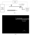
FIG. 1 is a schematic diagram of a laser induced discharge system for generating a long-distance controllable high-voltage discharge according to an embodiment of the present disclosure; and -
FIG. 2 shows a typical image of a meter-level high-voltage discharge along a laser path and generated by applying the method in the embodiments of the present disclosure. - In order to make the objectives, technical solutions, and advantages of embodiments of the present disclosure clearer, the following clearly and completely describes the technical solutions in the embodiments of the present disclosure with reference to the embodiments of the present disclosure. Apparently, the described embodiments are some rather than all of the embodiments. All other embodiments obtained by those of ordinary skill in the art based on the embodiments of the present disclosure without creative efforts shall fall within the protection scope of the present disclosure.
- As shown in
FIG. 1 and FIG. 2 , the embodiments provide a laser induced discharge system for generating a long-distance controllable high-voltage discharge, including a laser source, a guiding optical path, a discharge module, and a control system. The laser source in the embodiments is a high-power ultrashort pulse laser source, namely, an ultrashort pulse laser that is generated based on a titanium doped sapphire gain medium and a chirped pulse amplification technology and has a repetition frequency of 10 Hz, a wavelength of 800 nm, MJ-level energy, and an fs-level or ps-level pulse width. A nonlinear optical effect is generated when high-power ultrashort pulse laser is propagated in a medium, and a continuous long plasma channel can be produced through ionization in air based on a dynamic balance between a Kerr self-focusing effect and a plasma defocusing effect. - The discharge module includes an impulse voltage generator and a rod electrode. The impulse voltage generator is capable of generating a negative switching impulse voltage with a peak value of equal to or greater than 1.6 MV, a rod-plate gap of the rod electrode is greater than or equal to 2 m, a curvature radius of a tip of the rod electrode is 10 mm, the rod electrode is connected to a high voltage, and a plate electrode is grounded.
- The guiding optical path includes a plurality of reflectors and a convex lens. laser emitted by the laser source enters the convex lens after being reflected by the reflectors, and then is incident into the discharge module from the convex lens. As shown in
FIG. 1 , in the embodiments, the horizontally emitted laser is horizontally reflected into the convex lens 5 by using fourreflectors - In the embodiments, the control system includes a photoelectric detector, an oscilloscope, a delay controller, and an electro-optic/photoelectric conversion module. The photoelectric detector is connected to the oscilloscope, the oscilloscope is connected to the delay controller, the delay controller (a DG535 delay controller is adopted in the embodiments) is connected to the electro-optic/photoelectric conversion module, and the electro-optic/photoelectric conversion module is connected to the discharge module. The photoelectric detector detects an output signal of the laser source for the oscilloscope to read. Rising edge trigger is set for the oscilloscope to output a trigger signal to the DG535 delay controller when the signal is read. A delay between the signal output by the oscilloscope and a new trigger signal is set for the DG535 delay controller, and the new trigger signal is transmitted to an electro-optic conversion module of the electro-optic/photoelectric conversion module. After an optical signal is transmitted to a photoelectric conversion module of the electro-optic/photoelectric conversion module by using an optical fiber, a final electrical signal is transmitted to the impulse voltage generator. The trigger delay δt is set for the DG535 delay controller, namely, δt=1ms-t d-t f, where t d represents time from triggering of a first-level sphere gap of the impulse voltage generator in the discharge module to loading of a switching impulse voltage waveform to the rod electrode, there are 24 discharge sphere gaps inside the impulse voltage generator, namely, 24 levels of sphere gaps, the first-level sphere gap is a first-level sphere gap among the 24 levels of sphere gaps of the impulse voltage generator, and t f represents time of a rising edge of the impulse voltage waveform. The electro-optic conversion module is configured to convert a TTL signal into the optical signal, and the photoelectric conversion module is configured to convert the optical signal into a 10 kV pulse signal and trigger the first-level sphere gap of the impulse voltage generator. The laser source is turned on to output the laser at the repetition frequency of 10 Hz. An output first laser signal is detected by the photoelectric detector and becomes a trigger pulse of the first-level sphere gap of the impulse voltage generator after passing through the control system. A delay setting of the control system enables a second signal of a laser system to temporally coincide with a voltage pulse loaded on the rod electrode by the impulse voltage generator, thus generating a laser induced discharge. The guiding optical path guarantees spatial coordination between the laser system and the discharge module, such that the generated laser induced discharge is a long-distance high-voltage discharge along a laser path.
- In the embodiments, a distance between a laser emitting end of the guiding optical path and the tip of the rod electrode of the discharge module is calculated according to following formulae:


where k represents a wave number, a 0 represents a spot radius, P represents a laser peak power, P c represents a critical power of the laser when the laser generates ionization and makes laser filament, f represents a focal length of the convex lens, and zf represents a self-focusing effect of an incident gap of the laser; and - When the focal length of the convex lens is 10 m,

- That is, the empirical formula gives optimal spatial coordination between the laser system and the discharge module, which can realize a longest-distance discharge starting from the tip of the rod electrode. The trigger delay δt is set to 1ms-t d-t f for the DG535 delay controller, which achieves optimal temporal coordination between the laser system and the discharge module. Under the optimal spatial and temporal coordination between the two systems, a probability of the laser induced discharge (laser-triggered discharge developing along the laser path) can be equal to or greater than 99%, and a path of the laser induced discharge can reach a meter level, which is of great significance to the development of laser guided long-distance high-voltage discharge, laser induced lightning, long-distance laser detection, and other technologies.
- In the embodiments, a combination relationship and a position relationship of the reflectors in the guiding optical path and the geometric focal length of the convex lens are determined based on positions of the laser source and the rod electrode to meet optimal spatial coordination between the laser source and the discharge module, in other words, a distance between the convex lens and the rod electrode. The above spatial distance and delay should meet following conditions: When the first laser signal output by the laser source is detected by the photoelectric detector and becomes the trigger pulse of the first-level sphere gap of the impulse voltage generator after passing through the control system, the delay setting of the control system enables the second signal of the laser system to temporally coincide with the voltage pulse loaded on the rod electrode by the impulse voltage generator, thus generating the laser induced discharge. The guiding optical path guarantees the spatial coordination between the laser system and the discharge module, such that the generated laser induced discharge is the long-distance high-voltage discharge along the laser path.
- Based on the above method, the embodiments further provide a laser induced discharge method for generating a long-distance controllable high-voltage discharge, including following steps.
- Step 1: Build a discharge system, where the discharge system includes a laser system, a guiding optical path, a discharge module, and a control system; and the laser source reaches the discharge module through the guiding optical path.
- The control system includes a photoelectric detector, an oscilloscope, a delay controller, and an electro-optic/photoelectric conversion module. The photoelectric detector is connected to the oscilloscope, the oscilloscope is connected to the delay controller, the delay controller is connected to the electro-optic/photoelectric conversion module, and the electro-optic/photoelectric conversion module is connected to the discharge module.
- A distance between a laser emitting end of the guiding optical path and a tip of a rod electrode of the discharge module is calculated according to following formulae:


where k represents a wave number, a 0 represents a spot radius, P represents a laser peak power, P c represents a critical power of the laser when the laser generates ionization and makes laser filament, f represents a focal length of the convex lens, and zf represents a self-focusing effect of an incident gap of the laser. - A trigger delay δt is set for the delay controller, namely, δt=1 ms-t d-t f, where t d represents time from triggering of a first-level sphere gap of an impulse voltage generator in discharge module to loading of a switching impulse voltage waveform to the rod electrode, and t f represents time of a rising edge of the impulse voltage waveform.
- Step 2: Start the laser source, detect, by the photoelectric detector, a first laser output signal of the laser source for the oscilloscope to read, output, by the oscilloscope, a trigger signal to the delay controller when reading the signal, set a delay between the signal output by the oscilloscope and a new trigger signal for the delay controller, and transmit the new trigger signal to an electro-optic conversion module, and transmit a final electrical signal to the impulse voltage generator after an optical signal is transmitted to a photoelectric conversion module by using an optical fiber.
- Step 3: Trigger, by the impulse voltage generator, a discharge after receiving the trigger signal, where a delay setting of the control system enables a second signal of a laser system to temporally coincide with a voltage pulse loaded on the rod electrode by the impulse voltage generator, such that the discharge develops along a laser path.
- In the embodiments, the laser source is an ultrashort pulse laser that is generated based on a titanium doped sapphire gain medium and a chirped pulse amplification technology and has a repetition frequency of 10 Hz, a wavelength of 800 nm, MJ-level energy, and an fs-level or ps-level pulse width.
- The guiding optical path includes a plurality of reflectors and a convex lens. laser emitted by the laser source enters the convex lens after being reflected by the reflectors, and then is incident into the discharge module from the convex lens. A geometric focal length of the convex lens is 10 m.
- The discharge module includes the impulse voltage generator and the rod electrode. The impulse voltage generator is capable of generating a negative switching impulse voltage with a peak value of equal to or greater than 1.6 MV, a rod-plate gap of the rod electrode is greater than or equal to 2 m, a curvature radius of a tip of the rod electrode is 10 mm, the rod electrode is connected to a high voltage, and a plate electrode is grounded.
- In the embodiments, the photoelectric detector detects the output signal of the laser source for the oscilloscope to read. Rising edge trigger is set for the oscilloscope to output the trigger signal to the DG535 delay controller when the signal is read. The delay between the signal output by the oscilloscope and the new trigger signal is set for the DG535 delay controller, and the new trigger signal is transmitted to the electro-optic conversion module of the electro-optic/photoelectric conversion module. After the optical signal is transmitted to the photoelectric conversion module of the electro-optic/photoelectric conversion module by using the optical fiber, the final electrical signal is transmitted to the impulse voltage generator. The trigger delay δt is set for the DG535 delay controller, namely, δt=1ms-t d-t f, where t d represents the time from triggering of the first-level sphere gap of the impulse voltage generator in the discharge module to loading of the switching impulse voltage waveform to the rod electrode, and t f represents the time of the rising edge of the impulse voltage waveform. The electro-optic conversion module is configured to convert a TTL signal into the optical signal, and the photoelectric conversion module is configured to convert the optical signal into a 10 kV pulse signal and trigger the first-level sphere gap of the impulse voltage generator. The laser source is turned on to output the laser at the repetition frequency of 10 Hz. An output first laser signal is detected by the photoelectric detector and becomes a trigger pulse of the first-level sphere gap of the impulse voltage generator after passing through the control system. The delay setting of the control system enables the second signal of the laser system to temporally coincide with the voltage pulse loaded on the rod electrode by the impulse voltage generator, thus generating a laser induced discharge. The guiding optical path guarantees spatial coordination between the laser system and the discharge module, such that the generated laser induced discharge is a long-distance high-voltage discharge along a laser path.
- In the embodiments, a longest-distance discharge starting from the tip of the rod electrode can be realized based on the distance between the laser emitting end of the guiding optical path and the tip of the rod electrode of the discharge module, in other words, the above distance calculation formula gives optimal spatial coordination between the laser system and the discharge module. The trigger delay δt is set to 1ms-t d-t f for the DG535 delay controller, which achieves optimal temporal coordination between the laser system and the discharge module. Under the optimal spatial and temporal coordination between the two systems, a probability of the laser induced discharge (laser-triggered discharge developing along the laser path) can be equal to or greater than 99%, and a path of the laser induced discharge can reach a meter level, which is of great significance to the development of laser guided long-distance high-voltage discharge, laser induced lightning, long-distance laser detection, and other technologies.
- In the embodiments, a combination relationship and a position relationship of the reflectors in the guiding optical path and the geometric focal length of the convex lens are determined based on positions of the laser source and the rod electrode to meet optimal spatial coordination between the laser source and the discharge module, in other words, a distance between an emitting end of the convex lens and the rod electrode. The above spatial distance and delay should meet following conditions: When the first laser signal output by the laser source is detected by the photoelectric detector and becomes the trigger pulse of the first-level sphere gap of the impulse voltage generator after passing through the control system, the delay setting of the control system enables the second signal of the laser system to temporally coincide with the voltage pulse loaded on the rod electrode by the impulse voltage generator, thus generating the laser induced discharge. The guiding optical path guarantees the spatial coordination between the laser system and the discharge module, such that the generated laser induced discharge is the long-distance high-voltage discharge along the laser path.
- The foregoing embodiments are only used to explain the technical solutions of the present disclosure, and are not intended to limit the same. Although the present disclosure is described in detail with reference to the foregoing embodiments, those of ordinary skill in the art should understand that they can still modify the technical solutions described in the foregoing embodiments, or make equivalent substitutions on some technical features therein. These modifications or substitutions do not make the essence of the corresponding technical solutions deviate from the spirit and scope of the technical solutions of the embodiments of the present disclosure.
Claims (10)
- A laser induced discharge system for generating a long-distance controllable high-voltage discharge, comprising a laser system, a guiding optical path, a discharge module, and a control system, wherein a laser source of the laser system is a high-power ultrashort pulse laser source;the control system receives a laser signal of the laser system, and starts the discharge module based on the laser signal; and the control system is provided with a trigger delay;the guiding optical path comprises a plurality of reflectors (1, 2, 3, 4) and a convex lens (5); laser reaches the convex lens (5) after being reflected by the reflectors (1, 2, 3, 4), and then reaches the discharge module through the convex lens (5); and a distance between the convex lens (5) and a tip of a rod electrode of the discharge module is calculated according to following formulae:

 wherein k represents a wave number, a 0 represents a spot radius, P represents a laser peak power, P c represents a critical power of the laser when the laser generats ionization and makes laser filament, f represents a focal length of the convex lens (5), and zf represents a self-focusing effect of an incident gap of the laser; andthe trigger delay δt is equal to 1 ms-t d-t f, wherein t d represents time from triggering of a first-level sphere gap of an impulse voltage generator in the discharge module to loading of a switching impulse voltage waveform to the rod electrode, and t f represents time of a rising edge of the impulse voltage waveform.
 - The laser induced discharge system for generating a long-distance controllable high-voltage discharge according to claim 1, wherein the laser source is an ultrashort pulse laser that is generated based on a titanium doped sapphire gain medium and a chirped pulse amplification technology and has a repetition frequency of 10 Hz, a wavelength of 800 nm, MJ-level energy, and an fs-level or ps-level pulse width.
- The laser induced discharge system for generating a long-distance controllable high-voltage discharge according to claim 1 or 2, wherein a geometric focal length of the convex lens (5) is 10 m.
- The laser induced discharge system for generating a long-distance controllable high-voltage discharge according to claim 1 or 2, wherein the discharge module comprises the impulse voltage generator and the rod electrode, the impulse voltage generator is capable of generating a negative switching impulse voltage with a peak value of equal to or greater than 1.6 MV, a rod-plate gap of the rod electrode is greater than or equal to 2 m, a curvature radius of the tip of the rod electrode is 10 mm, the rod electrode is connected to a high voltage, and a plate electrode is grounded.
- The laser induced discharge system for generating a long-distance controllable high-voltage discharge according to claim 1 or 2, wherein the control system comprises a photoelectric detector, an oscilloscope, a delay controller, and an electro-optic/photoelectric conversion module, the photoelectric detector is connected to the oscilloscope, the oscilloscope is connected to the delay controller, the delay controller is connected to the electro-optic/photoelectric conversion module, and the electro-optic/photoelectric conversion module is connected to the discharge module.
- A laser induced discharge method for generating a long-distance controllable high-voltage discharge, comprising following steps:step 1: building a discharge system, wherein the discharge system comprises a laser system, a guiding optical path, a discharge module, and a control system; a laser source of the laser system is a high-power ultrashort pulse laser source; the control system receives a laser signal of the laser system, and starts the discharge module based on the laser signal; and the control system is provided with a trigger delay;the guiding optical path comprises a plurality of reflectors (1, 2, 3, 4) and a convex lens (5); laser reaches the convex lens (5) after being reflected by the reflectors (1, 2, 3, 4), and then reaches the discharge module through the convex lens (5); and a distance between the convex lens (5) and a tip of a rod electrode of the discharge module is calculated according to following formulae:

 wherein k represents a wave number, a 0 represents a spot radius, P represents a laser peak power, P c represents a critical power of the laser when the laser generates ionization and makes laser filament, f represents a focal length of the convex lens (5), and zf represents a self-focusing effect of an incident gap of the laser; andthe trigger delay δt is equal to 1 ms-t d-t f, wherein t d represents time from triggering of a first-level sphere gap of an impulse voltage generator in the discharge module to loading of a switching impulse voltage waveform to the rod electrode, and t f represents time of a rising edge of the impulse voltage waveform;step 2: starting the laser source, detecting, by the control system, a first laser output signal of the laser source to form a trigger signal, and transmitting the trigger signal to the impulse voltage generator; andstep 3: triggering, by the impulse voltage generator, a discharge after receiving the trigger signal, wherein a delay setting of the control system enables a second signal of the laser system to temporally coincide with a voltage pulse loaded on the rod electrode by the impulse voltage generator, such that the discharge develops along a laser path.
 - The laser induced discharge method for generating a long-distance controllable high-voltage discharge according to claim 6, wherein the laser source is an ultrashort pulse laser that is generated based on a titanium doped sapphire gain medium and a chirped pulse amplification technology and has a repetition frequency of 10 Hz, a wavelength of 800 nm, MJ-level energy, and an fs-level or ps-level pulse width.
- The laser induced discharge method for generating a long-distance controllable high-voltage discharge according to claim 6 or 7, wherein a geometric focal length of the convex lens (5) is 10 m.
- The laser induced discharge method for generating a long-distance controllable high-voltage discharge according to claim 6 or 7, wherein the discharge module comprises the impulse voltage generator and the rod electrode, the impulse voltage generator is capable of generating a negative switching impulse voltage with a peak value of equal to or greater than 1.6 MV, a rod-plate gap of the rod electrode is greater than or equal to 2 m, a curvature radius of the tip of the rod electrode is 10 mm, the rod electrode is connected to a high voltage, and a plate electrode is grounded.
- The laser induced discharge method for generating a long-distance controllable high-voltage discharge according to claim 6 or 7, wherein the control system comprises a photoelectric detector, an oscilloscope, a delay controller, and an electro-optic/photoelectric conversion module, the photoelectric detector is connected to the oscilloscope, the oscilloscope is connected to the delay controller, the delay controller is connected to the electro-optic/photoelectric conversion module, and the electro-optic/photoelectric conversion module is connected to the discharge module.
Applications Claiming Priority (2)
| Application Number | Priority Date | Filing Date | Title |
|---|---|---|---|
| CN202111295996.XA CN114019326B (en) | 2021-11-03 | 2021-11-03 | Laser-induced discharge method and system for generating long-distance controllable high-voltage discharge |
| PCT/CN2022/129101 WO2023078270A1 (en) | 2021-11-03 | 2022-11-01 | Laser-induced discharging method and system for generating long-range controllable high-voltage discharge |
Publications (2)
| Publication Number | Publication Date |
|---|---|
| EP4202453A1 true EP4202453A1 (en) | 2023-06-28 |
| EP4202453A4 EP4202453A4 (en) | 2024-05-01 |
Family
ID=80060647
Family Applications (1)
| Application Number | Title | Priority Date | Filing Date |
|---|---|---|---|
| EP22859567.4A Pending EP4202453A4 (en) | 2021-11-03 | 2022-11-01 | LASER-INDUCED DISCHARGE METHOD AND SYSTEM FOR GENERATING A CONTROLLED LONG-RANGE HIGH-VOLTAGE DISCHARGE |
Country Status (3)
| Country | Link |
|---|---|
| EP (1) | EP4202453A4 (en) |
| CN (1) | CN114019326B (en) |
| WO (1) | WO2023078270A1 (en) |
Families Citing this family (1)
| Publication number | Priority date | Publication date | Assignee | Title |
|---|---|---|---|---|
| CN114019326B (en) * | 2021-11-03 | 2023-09-26 | 国网安徽省电力有限公司电力科学研究院 | Laser-induced discharge method and system for generating long-distance controllable high-voltage discharge |
Family Cites Families (13)
| Publication number | Priority date | Publication date | Assignee | Title |
|---|---|---|---|---|
| JP2000133408A (en) * | 1998-10-30 | 2000-05-12 | Toshiba Corp | Laser induced discharge generator and discharge generation method |
| CN101620183B (en) * | 2009-07-28 | 2011-03-02 | 华南理工大学 | Photoelectric double-pulse laser induced breakdown spectrograph and spectral analysis method |
| CN102854172A (en) * | 2012-10-15 | 2013-01-02 | 无锡天授信息科技有限公司 | Double-pulse laser induced breakdown spectrograph system and spectral analysis method thereof |
| CN104779944B (en) * | 2015-04-27 | 2018-01-05 | 西安交通大学 | A kind of gap switch and method based on the triggering of axially and radially laser beam multiple spot |
| CN105316472B (en) * | 2015-08-13 | 2017-11-17 | 江苏大学 | A kind of method and device for improving induced with laser shock wave pressure |
| CN106198491B (en) * | 2016-07-06 | 2019-02-26 | 中国科学院上海光学精密机械研究所 | Apparatus and method for improving breakdown point distance of laser-induced air breakdown |
| CN208221007U (en) * | 2018-04-09 | 2018-12-11 | 中国人民解放军国防科技大学 | Parallel polar plate type laser supported pulse plasma thruster |
| CN109212447B (en) * | 2018-08-14 | 2021-08-24 | 国网陕西省电力公司电力科学研究院 | A portable fast pulse generator and method of making the same |
| CN108872848A (en) * | 2018-08-14 | 2018-11-23 | 国网陕西省电力公司电力科学研究院 | A kind of fast pulse generating device for superfrequency calibration |
| CN109888613A (en) * | 2019-01-02 | 2019-06-14 | 广州供电局有限公司 | Induced with laser gap breakdown switchgear based on dipulse |
| CN113125906B (en) * | 2021-03-31 | 2024-08-13 | 国网安徽省电力有限公司电力科学研究院 | A system and method for synchronously observing multiple physical quantities of long air gap discharge |
| CN113533918A (en) * | 2021-08-26 | 2021-10-22 | 华北电力大学(保定) | Analysis method of onset time delay of long air gap discharge current injection under positive operating shock |
| CN114019326B (en) * | 2021-11-03 | 2023-09-26 | 国网安徽省电力有限公司电力科学研究院 | Laser-induced discharge method and system for generating long-distance controllable high-voltage discharge |
-
2021
- 2021-11-03 CN CN202111295996.XA patent/CN114019326B/en active Active
-
2022
- 2022-11-01 EP EP22859567.4A patent/EP4202453A4/en active Pending
- 2022-11-01 WO PCT/CN2022/129101 patent/WO2023078270A1/en not_active Ceased
Also Published As
| Publication number | Publication date |
|---|---|
| EP4202453A4 (en) | 2024-05-01 |
| WO2023078270A1 (en) | 2023-05-11 |
| CN114019326A (en) | 2022-02-08 |
| CN114019326B (en) | 2023-09-26 |
Similar Documents
| Publication | Publication Date | Title |
|---|---|---|
| Kaganovich et al. | High efficiency guiding of terawatt subpicosecond laser pulses in a capillary discharge plasma channel | |
| Zhang et al. | Experimental study on conduction current of positive nanosecond-pulse diffuse discharge at atmospheric pressure | |
| US4220842A (en) | Method of removing material from a workpiece | |
| Guenther et al. | A review of laser-triggered switching | |
| Hooker et al. | Guiding of high-intensity picosecond laser pulses in a discharge-ablated capillary waveguide | |
| JP4793936B2 (en) | Apparatus and method for adjusting collision timing of electron beam and laser beam | |
| US4447151A (en) | Method and apparatus for fast laser pulse detection using gaseous plasmas | |
| CN104779944B (en) | A kind of gap switch and method based on the triggering of axially and radially laser beam multiple spot | |
| CN114019326B (en) | Laser-induced discharge method and system for generating long-distance controllable high-voltage discharge | |
| Jordan et al. | Microwave breakdown in slots | |
| Rapoport et al. | KrF laser-triggered SF6 spark gap for low jitter timing | |
| Rep’ev et al. | Dynamics of the optical emission from a high-voltage diffuse discharge in a rod-plane electrode system in atmospheric-pressure air | |
| US3422307A (en) | Electric arc device with a photoelectric starting electrode | |
| Mourou et al. | Electrooptic prepulse suppression for fusion laser systems | |
| Woodworth et al. | 170-kV laser-triggered water switch experiments | |
| Woodworth et al. | Green-laser-triggered water switching at 1.6 MV | |
| Simpson et al. | Triggering of a High Pressure Air-filled High Voltage Spark Gap Switch Using Fiber-Delivered Laser Induced Plasmas Resulting in Sub-nanosecond Jitter at Low Percentages of Self-Break. | |
| US11576251B2 (en) | Reflective optical system | |
| MacGregor et al. | The design and operation of a compact high-voltage, high pulse repetition frequency trigger generator | |
| Fu et al. | Extending Femtosecond Laser Superfilamentation in Air With a Phase Mask | |
| RU2826450C1 (en) | Method of spatially directed laser acceleration of beam of charged particles in plasma with inhomogeneous concentration of electrons | |
| Tarasenko et al. | On the initiation of a spark discharge upon the breakdown of nitrogen and air in a nonuniform electric field | |
| RU2810648C1 (en) | Method for generating synchronization pulses for high-voltage spark gap with laser triggering and device for its implementation | |
| Vergne et al. | High-voltage rectifier diodes used as photoconductive device for microwave pulse generation | |
| Kopiczynski et al. | Multiple breakdown in helium generated by hybrid 10 μm CO2 laser pulses |
Legal Events
| Date | Code | Title | Description |
|---|---|---|---|
| STAA | Information on the status of an ep patent application or granted ep patent |
Free format text: STATUS: UNKNOWN |
|
| STAA | Information on the status of an ep patent application or granted ep patent |
Free format text: STATUS: THE INTERNATIONAL PUBLICATION HAS BEEN MADE |
|
| PUAI | Public reference made under article 153(3) epc to a published international application that has entered the european phase |
Free format text: ORIGINAL CODE: 0009012 |
|
| STAA | Information on the status of an ep patent application or granted ep patent |
Free format text: STATUS: REQUEST FOR EXAMINATION WAS MADE |
|
| 17P | Request for examination filed |
Effective date: 20230309 |
|
| AK | Designated contracting states |
Kind code of ref document: A1 Designated state(s): AL AT BE BG CH CY CZ DE DK EE ES FI FR GB GR HR HU IE IS IT LI LT LU LV MC ME MK MT NL NO PL PT RO RS SE SI SK SM TR |
|
| A4 | Supplementary search report drawn up and despatched |
Effective date: 20240403 |
|
| RIC1 | Information provided on ipc code assigned before grant |
Ipc: H05H 1/48 20060101ALI20240326BHEP Ipc: H01T 2/00 20060101ALI20240326BHEP Ipc: G01R 31/12 20200101AFI20240326BHEP |
|
| DAV | Request for validation of the european patent (deleted) | ||
| DAX | Request for extension of the european patent (deleted) |