EP4202421A1 - Method of detecting coating wear - Google Patents
Method of detecting coating wear Download PDFInfo
- Publication number
- EP4202421A1 EP4202421A1 EP22211195.7A EP22211195A EP4202421A1 EP 4202421 A1 EP4202421 A1 EP 4202421A1 EP 22211195 A EP22211195 A EP 22211195A EP 4202421 A1 EP4202421 A1 EP 4202421A1
- Authority
- EP
- European Patent Office
- Prior art keywords
- coating
- component
- set forth
- dye
- hardness
- Prior art date
- Legal status (The legal status is an assumption and is not a legal conclusion. Google has not performed a legal analysis and makes no representation as to the accuracy of the status listed.)
- Pending
Links
Images

Classifications
-
- G—PHYSICS
- G01—MEASURING; TESTING
- G01B—MEASURING LENGTH, THICKNESS OR SIMILAR LINEAR DIMENSIONS; MEASURING ANGLES; MEASURING AREAS; MEASURING IRREGULARITIES OF SURFACES OR CONTOURS
- G01B11/00—Measuring arrangements characterised by the use of optical techniques
- G01B11/02—Measuring arrangements characterised by the use of optical techniques for measuring length, width or thickness
- G01B11/06—Measuring arrangements characterised by the use of optical techniques for measuring length, width or thickness for measuring thickness ; e.g. of sheet material
- G01B11/0616—Measuring arrangements characterised by the use of optical techniques for measuring length, width or thickness for measuring thickness ; e.g. of sheet material of coating
- G01B11/0625—Measuring arrangements characterised by the use of optical techniques for measuring length, width or thickness for measuring thickness ; e.g. of sheet material of coating with measurement of absorption or reflection
-
- G—PHYSICS
- G01—MEASURING; TESTING
- G01N—INVESTIGATING OR ANALYSING MATERIALS BY DETERMINING THEIR CHEMICAL OR PHYSICAL PROPERTIES
- G01N21/00—Investigating or analysing materials by the use of optical means, i.e. using sub-millimetre waves, infrared, visible or ultraviolet light
- G01N21/84—Systems specially adapted for particular applications
- G01N21/8422—Investigating thin films, e.g. matrix isolation method
-
- G—PHYSICS
- G01—MEASURING; TESTING
- G01N—INVESTIGATING OR ANALYSING MATERIALS BY DETERMINING THEIR CHEMICAL OR PHYSICAL PROPERTIES
- G01N21/00—Investigating or analysing materials by the use of optical means, i.e. using sub-millimetre waves, infrared, visible or ultraviolet light
- G01N21/84—Systems specially adapted for particular applications
- G01N21/88—Investigating the presence of flaws or contamination
- G01N21/8803—Visual inspection
-
- G—PHYSICS
- G05—CONTROLLING; REGULATING
- G05B—CONTROL OR REGULATING SYSTEMS IN GENERAL; FUNCTIONAL ELEMENTS OF SUCH SYSTEMS; MONITORING OR TESTING ARRANGEMENTS FOR SUCH SYSTEMS OR ELEMENTS
- G05B23/00—Testing or monitoring of control systems or parts thereof
- G05B23/02—Electric testing or monitoring
- G05B23/0205—Electric testing or monitoring by means of a monitoring system capable of detecting and responding to faults
- G05B23/0259—Electric testing or monitoring by means of a monitoring system capable of detecting and responding to faults characterized by the response to fault detection
- G05B23/0283—Predictive maintenance, e.g. involving the monitoring of a system and, based on the monitoring results, taking decisions on the maintenance schedule of the monitored system; Estimating remaining useful life [RUL]
-
- G—PHYSICS
- G01—MEASURING; TESTING
- G01N—INVESTIGATING OR ANALYSING MATERIALS BY DETERMINING THEIR CHEMICAL OR PHYSICAL PROPERTIES
- G01N21/00—Investigating or analysing materials by the use of optical means, i.e. using sub-millimetre waves, infrared, visible or ultraviolet light
- G01N21/84—Systems specially adapted for particular applications
- G01N21/8422—Investigating thin films, e.g. matrix isolation method
- G01N2021/8427—Coatings
-
- G—PHYSICS
- G01—MEASURING; TESTING
- G01N—INVESTIGATING OR ANALYSING MATERIALS BY DETERMINING THEIR CHEMICAL OR PHYSICAL PROPERTIES
- G01N21/00—Investigating or analysing materials by the use of optical means, i.e. using sub-millimetre waves, infrared, visible or ultraviolet light
- G01N21/84—Systems specially adapted for particular applications
- G01N21/88—Investigating the presence of flaws or contamination
- G01N21/95—Investigating the presence of flaws or contamination characterised by the material or shape of the object to be examined
- G01N21/952—Inspecting the exterior surface of cylindrical bodies or wires
Definitions
- This application relates to a method of detecting wear in a coating such as found on electrical harnesses.
- Modern systems incorporate a number of electrical systems.
- electrical wires are routed between components, and are held in place such as by clips.
- these clips are formed of a metal whereas the electrical harnesses have a non-metallic sheathing.
- Coatings are often placed on the outside of the sheathing to protect the sheathing from undue wear. However, and in particular, when the system is subject to a vibration there can be undue wear as the metallic clips are harder than the non-metallic sheathing.
- a method of inspecting a component includes the steps of identifying a component having an outer surface of a first hardness, and mounted with a holding member of a second hardness which is greater than the first hardness.
- a protective coating is provided about the first component, and the protective coating having a dye which absorbs a particular range of electromagnetic wavelengths. The amount of the dye remaining in the coating is inspected to identify an amount of wear of the coating.
- Figure 1A shows a system 20 such as may be found in any number of industrial applications.
- system 20 is mounted upon an aircraft which is a subject to a good deal of vibration.
- An electrical harness 22 is secured to a metal conduit 24 through a metal clip 26 having a loop 28 surrounding the harness 22. This detail of the harness 22, clip 26 and loop 28 are shown enlarged in the exploded portion of Figure 1A .
- Figure 1B is a cross-section through an example electrical harness 22.
- a central electric wire 30 is surrounded by the sheathing 32.
- a protective coating 34 is placed outwardly of the sheathing 32. The thickness of the coating 34 is exaggerated to illustrate the fact of the sheathing.
- a dye 99 is shown included in the coating material. In practice the dye will be uniformly distributed through coating 34.
- the dye might be ultraviolet inspectable dyes which absorb light over a specific range of the ultraviolet wavelength.
- silane-functionalized quaternary ammonium compounds One example would be silane-functionalized quaternary ammonium compounds. With such dyes incorporated into the coating, one may monitor the condition of the coating by applying UV light to the electrical harness, and evaluating the amount of coating which appears to be left.
- silane-functionalized quaternary ammonium compounds An additional benefit of the silane-functionalized quaternary ammonium compounds is that it also protects the underlying substrate from bacterial or fungal growth which will facilitate the ability to pass stringent aerospace fungus resistant requirements.
- the dye and coating may be solvent-based or may be water-based.
- the inspection method may include a black light to be applied on the electrical harness 22. This may be done while the harness is still in place on the aircraft.
- Figure 2 shows a first inspection method.
- a black light 62 is applied to the electrical harness 22 which causes the dye to become visible.
- a smartphone 50 photographs the amount of dye visible at that point.
- the dye may be fluorescent and capable of absorbing in the UV spectrum and would emit in the visible spectrum.
- the compound may absorb radiation in the range of 100-415 nm wavelengths, and more preferably in the range of 365-415 nm wavelengths and emit radiation in the 100-1000 nm wavelength, but most preferably emit visible light in the 380-740 nm wavelength.
- the fluorescent dyes are preferably transparent in the presence of visual light and uncolored so as not to alter the color and/or transparency of the nominal coating 34 or the surface of the substrate, here sheathing 32.
- the dye may be a fluorescent dye, a pigment, a colorant, or a brightener as long as it meets the wavelength requirement to allow a method of inspection.
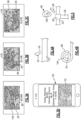
- Figure 3A shows a photo of a portion 35 of harness 22, which may be taken such as by smartphone 50. Areas 134 are shown as one color whereas areas 38 are shown as another. Areas 134 are the remainder of the coating, and the amount of areas 38 show wear, or lack of the coating.
- Figure 3B shows another photo wherein there is additional wear and more of the worn area 38 compared to Figure 3A .
- Figure 3C shows yet a further photo wherein there is even more wear 38, and the wear 38 is becoming even more intense.
- Figure 3C may be indicative of a need to recoat the electrical harness.
- Figure 3D shows smartphone 50 having the photo 52.
- the smartphone 50 is programmed to evaluate the percentage of wear of the coating in the particular photo.
- Known software programs capable of determining the relative percentage of two areas in an image may be utilized to determine the relative percentage of area 134 and 38.
- a light sensitive dye is included into a coating which is placed upon a conduit such as an electrical harness.
- a conduit such as an electrical harness.
- an electrical harness is specifically disclosed, the teaching of this disclosure could also apply to other components which are held in place by clips or other holding members which are harder than the component itself such that there could be undue wear. As one example, there may be fluid conduits that would benefit from this disclosure.
- the inspecting step may include a step of photographing a portion of the component.
- a device is utilized to take the photograph, and the photograph then being evaluated with a program capable of identifying a percentage of remaining coating on the component.
- the device is a smartphone.
- Figure 4A shows a first corrective step in which a coating tool 53 is applying coating 54 to the harness 22.
- the harness 22 would preferably be removed from the clip prior to performing this coating.
- the coating would be performed as a result of the inspection as previously described.
- the quality of the coating is periodically inspected, such as looking for the ultraviolet light response.
- the use of infrared sensitive dyes would also come within the scope of this disclosure.
- Figure 4B shows an alternative corrective step. If undue wear is identified on the electrical harness 22 at a particular location with regard to a clip 26 and its loop 28, a designer may include a protective grommet 154 which is of a material similar to the material of the sheathing surrounding the harness 22. Now, should there be undue wear due to vibration it would occur to the grommet, and not likely damage the harness 22.
- Figure 5 shows such a method wherein a user 60 wears goggles 100 useful for seeing the dye. That is the smartphone need not be used, and the inspection is visual. A black light 62 again applies light to allow the inspection. The method would otherwise be similar to the specifically disclosed method above.
- a method of inspecting a component under this disclosure could be said to include the steps of identifying a component having an outer surface of a first hardness, and mounted with a holding member of a second hardness which is greater than the first hardness.
- a protective coating provided about the first component, and the protective coating having a dye which absorbs a particular range of electromagnetic wavelengths. The amount of the dye remaining in the coating is inspected to identify an amount of wear of the coating.
Landscapes
- Physics & Mathematics (AREA)
- General Physics & Mathematics (AREA)
- Analytical Chemistry (AREA)
- Health & Medical Sciences (AREA)
- Life Sciences & Earth Sciences (AREA)
- Chemical & Material Sciences (AREA)
- Biochemistry (AREA)
- General Health & Medical Sciences (AREA)
- Immunology (AREA)
- Pathology (AREA)
- Mathematical Physics (AREA)
- Engineering & Computer Science (AREA)
- Automation & Control Theory (AREA)
- Investigating Materials By The Use Of Optical Means Adapted For Particular Applications (AREA)
- Investigating Or Analysing Materials By Optical Means (AREA)
Abstract
Description
- This application relates to a method of detecting wear in a coating such as found on electrical harnesses.
- Modern systems incorporate a number of electrical systems. Typically, electrical wires are routed between components, and are held in place such as by clips. In many applications these clips are formed of a metal whereas the electrical harnesses have a non-metallic sheathing.
- Coatings are often placed on the outside of the sheathing to protect the sheathing from undue wear. However, and in particular, when the system is subject to a vibration there can be undue wear as the metallic clips are harder than the non-metallic sheathing.
- Of course, undue wear on the sheathing would be undesirable.
- A method of inspecting a component includes the steps of identifying a component having an outer surface of a first hardness, and mounted with a holding member of a second hardness which is greater than the first hardness. A protective coating is provided about the first component, and the protective coating having a dye which absorbs a particular range of electromagnetic wavelengths. The amount of the dye remaining in the coating is inspected to identify an amount of wear of the coating.
- These and other features of this disclosure can be best understood from the following specification and drawings, the following of which is a brief description.
-
-
Figure 1A shows an example system. -
Figure 1B is a cross-section through an electrical harness as part of the system ofFigure 1 . -
Figure 2 shows a first inspection method. -
Figure 3A shows an image of a sheathing having its coating relatively intact. -
Figure 3B shows an image of a sheathing with a medium amount of wear. -
Figure 3C shows an image of a sheathing with even further wear. -
Figure 3D is an example display for a method according to this disclosure. -
Figure 4A shows a first corrective step. -
Figure 4B shows a second corrective step including a design modification. -
Figure 5 shows an alternative inspection method. -
Figure 1A shows asystem 20 such as may be found in any number of industrial applications. In onespecific application system 20 is mounted upon an aircraft which is a subject to a good deal of vibration. - An
electrical harness 22 is secured to ametal conduit 24 through ametal clip 26 having aloop 28 surrounding theharness 22. This detail of theharness 22,clip 26 andloop 28 are shown enlarged in the exploded portion ofFigure 1A . -
Figure 1B is a cross-section through an exampleelectrical harness 22. A centralelectric wire 30 is surrounded by thesheathing 32. Further, aprotective coating 34 is placed outwardly of thesheathing 32. The thickness of thecoating 34 is exaggerated to illustrate the fact of the sheathing. - In a method according to this invention, a
dye 99 is shown included in the coating material. In practice the dye will be uniformly distributed through coating 34. - In one example, the dye might be ultraviolet inspectable dyes which absorb light over a specific range of the ultraviolet wavelength.
- On the other hand, other dyes which absorb light over the infrared band may be utilized.
- One example would be silane-functionalized quaternary ammonium compounds. With such dyes incorporated into the coating, one may monitor the condition of the coating by applying UV light to the electrical harness, and evaluating the amount of coating which appears to be left.
- An additional benefit of the silane-functionalized quaternary ammonium compounds is that it also protects the underlying substrate from bacterial or fungal growth which will facilitate the ability to pass stringent aerospace fungus resistant requirements. The dye and coating may be solvent-based or may be water-based.
- In one embodiment, the inspection method may include a black light to be applied on the
electrical harness 22. This may be done while the harness is still in place on the aircraft. -
Figure 2 shows a first inspection method. Ablack light 62 is applied to theelectrical harness 22 which causes the dye to become visible. Asmartphone 50 photographs the amount of dye visible at that point. - The dye may be fluorescent and capable of absorbing in the UV spectrum and would emit in the visible spectrum. The compound may absorb radiation in the range of 100-415 nm wavelengths, and more preferably in the range of 365-415 nm wavelengths and emit radiation in the 100-1000 nm wavelength, but most preferably emit visible light in the 380-740 nm wavelength.
- The fluorescent dyes are preferably transparent in the presence of visual light and uncolored so as not to alter the color and/or transparency of the
nominal coating 34 or the surface of the substrate, here sheathing 32. The dye may be a fluorescent dye, a pigment, a colorant, or a brightener as long as it meets the wavelength requirement to allow a method of inspection. - As an example,
Figure 3A shows a photo of aportion 35 ofharness 22, which may be taken such as bysmartphone 50.Areas 134 are shown as one color whereasareas 38 are shown as another.Areas 134 are the remainder of the coating, and the amount ofareas 38 show wear, or lack of the coating. -
Figure 3B shows another photo wherein there is additional wear and more of theworn area 38 compared toFigure 3A . -
Figure 3C shows yet a further photo wherein there is evenmore wear 38, and thewear 38 is becoming even more intense.Figure 3C may be indicative of a need to recoat the electrical harness. -
Figure 3D showssmartphone 50 having thephoto 52. Thesmartphone 50 is programmed to evaluate the percentage of wear of the coating in the particular photo. Known software programs capable of determining the relative percentage of two areas in an image may be utilized to determine the relative percentage ofarea - Now, in a method according to this invention, a light sensitive dye is included into a coating which is placed upon a conduit such as an electrical harness. While an electrical harness is specifically disclosed, the teaching of this disclosure could also apply to other components which are held in place by clips or other holding members which are harder than the component itself such that there could be undue wear. As one example, there may be fluid conduits that would benefit from this disclosure.
- The inspecting step may include a step of photographing a portion of the component.
- A device is utilized to take the photograph, and the photograph then being evaluated with a program capable of identifying a percentage of remaining coating on the component. The device is a smartphone.
-
Figure 4A shows a first corrective step in which acoating tool 53 is applying coating 54 to theharness 22. Theharness 22 would preferably be removed from the clip prior to performing this coating. The coating would be performed as a result of the inspection as previously described. - The quality of the coating is periodically inspected, such as looking for the ultraviolet light response. As mentioned above, the use of infrared sensitive dyes would also come within the scope of this disclosure.
-
Figure 4B shows an alternative corrective step. If undue wear is identified on theelectrical harness 22 at a particular location with regard to aclip 26 and itsloop 28, a designer may include aprotective grommet 154 which is of a material similar to the material of the sheathing surrounding theharness 22. Now, should there be undue wear due to vibration it would occur to the grommet, and not likely damage theharness 22. -
Figure 5 shows such a method wherein auser 60 wearsgoggles 100 useful for seeing the dye. That is the smartphone need not be used, and the inspection is visual. Ablack light 62 again applies light to allow the inspection. The method would otherwise be similar to the specifically disclosed method above. - A method of inspecting a component under this disclosure could be said to include the steps of identifying a component having an outer surface of a first hardness, and mounted with a holding member of a second hardness which is greater than the first hardness. A protective coating provided about the first component, and the protective coating having a dye which absorbs a particular range of electromagnetic wavelengths. The amount of the dye remaining in the coating is inspected to identify an amount of wear of the coating.
- Although embodiments have been disclosed, a worker of skill in this art would understand that modifications would come within the scope of this disclosure. For that reason the following claims should be studied to determine the true scope and content.
Claims (15)
- A method of inspecting a component comprising the steps of:identifying a component having an outer surface of a first hardness, and mounted with a holding member of a second hardness which is greater than the first hardness;providing a protective coating about the first component, and the protective coating having a dye which absorbs a particular range of electromagnetic wavelengths; andinspecting the amount of the dye remaining in the coating to identify an amount of wear of the coating.
- The method as set forth in claim 1, wherein the first component is a conduit and a second component is a clip for holding the conduit.
- The method as set forth in claim 2, wherein the conduit is an electrical harness having an outer sheathing which is non-metallic.
- The method as set forth in claim 3, wherein the clip is metallic.
- The method as set forth in claim 4, wherein the dye absorbs light in a range of 100-415nm wavelengths, and preferably wherein the dye absorbs light in a range of 365-415nm wavelengths.
- The method as set forth in claim 4, wherein a black light is applied to the conduit as part of the inspecting step.
- The method as set forth in claim 4, wherein if undue wear on the coating is identified a need to recoat the first component is determined, and preferably wherein a coating is applied to the component after the need to recoat is identified.
- The method as set forth in claim 4, wherein the dye has at least one of antibacterial and antifungal growth properties.
- The method as set forth in claim 2, wherein if undue wear is determined at a particular location a grommet may be placed between the conduit and the clip to protect the conduit.
- The method as set forth in claim 1, wherein the dye is a silane-functionalized quaternary ammonium compound.
- The method as set forth in claim 1, wherein goggles are worn in the inspecting step which allow a wearer to identify the quality of the coating.
- The method as set forth in claim 1, wherein the dye has at least one of antibacterial and antifungal growth properties.
- The method as set forth in claim 1, wherein the inspecting step includes a step of photographing a portion of the component, and preferably wherein a device is utilized to take the photograph, and the photograph then being evaluated with a program capable of identifying a percentage of remaining coating on the component, and more preferably wherein the device is a smartphone.
- The method as set forth in claim 1, wherein if undue wear on the coating is identified a need to recoat the first component is determined, and preferably wherein a coating is applied to the component after the need to recoat is identified.
- The method as set forth in claim 1, wherein the dye absorbs light in a range of 100-415 nm wavelengths.
Applications Claiming Priority (2)
| Application Number | Priority Date | Filing Date | Title |
|---|---|---|---|
| US202163293925P | 2021-12-27 | 2021-12-27 | |
| US17/592,822 US12038268B2 (en) | 2021-12-27 | 2022-02-04 | Method of detecting coating wear |
Publications (1)
| Publication Number | Publication Date |
|---|---|
| EP4202421A1 true EP4202421A1 (en) | 2023-06-28 |
Family
ID=84387948
Family Applications (1)
| Application Number | Title | Priority Date | Filing Date |
|---|---|---|---|
| EP22211195.7A Pending EP4202421A1 (en) | 2021-12-27 | 2022-12-02 | Method of detecting coating wear |
Country Status (2)
| Country | Link |
|---|---|
| US (1) | US12038268B2 (en) |
| EP (1) | EP4202421A1 (en) |
Citations (4)
| Publication number | Priority date | Publication date | Assignee | Title |
|---|---|---|---|---|
| US20030081203A1 (en) * | 2001-10-30 | 2003-05-01 | Chen Yen Lane | Method of detecting wear on a substrate using a fluorescent Indicator |
| FR2836229A1 (en) * | 2002-02-15 | 2003-08-22 | Lilian Martinez | Control of the integrity and/or degradation of a coating involves using a coating that has detectable luminescence under electromagnetic excitation |
| US20130057849A1 (en) * | 2011-09-01 | 2013-03-07 | Nike, Inc. | Coating Inspection Device |
| EP3809119A1 (en) * | 2019-10-15 | 2021-04-21 | Compagnie Plastic Omnium SE | Device and method for assessing the quality of a coating |
Family Cites Families (8)
| Publication number | Priority date | Publication date | Assignee | Title |
|---|---|---|---|---|
| US6155066A (en) * | 1998-09-10 | 2000-12-05 | Century Manufacturing Company | Injector, methods for using injector, and kit |
| US6861154B2 (en) | 2002-09-26 | 2005-03-01 | Ecolab, Inc. | Coating wear indicator |
| JP2014216118A (en) * | 2013-04-24 | 2014-11-17 | 矢崎総業株式会社 | Insulation wire |
| JP2015191709A (en) | 2014-03-27 | 2015-11-02 | 住友電気工業株式会社 | Wear-detecting layer-equipped coated structure and method for detecting wear of coated structure |
| FR3082669B1 (en) * | 2018-06-15 | 2021-09-03 | A Raymond Et Cie | METAL CLIP FOR ELECTRICAL CONNECTION FROM A CONDUCTING WIRE TO A METAL ELEMENT |
| DE102019216245B3 (en) * | 2019-10-22 | 2020-11-26 | Robert Bosch Gmbh | Process for the detection of paint residues on a surface |
| US11536662B2 (en) * | 2020-06-24 | 2022-12-27 | B/E Aerospace, Inc. | Methods for detecting antimicrobial surface coatings using fluorescent indicators |
| CN114921981B (en) * | 2022-06-20 | 2024-04-09 | 南通大学 | Flame retardant coating dyed para-aramid fabric and dyeing method thereof |
-
2022
- 2022-02-04 US US17/592,822 patent/US12038268B2/en active Active
- 2022-12-02 EP EP22211195.7A patent/EP4202421A1/en active Pending
Patent Citations (4)
| Publication number | Priority date | Publication date | Assignee | Title |
|---|---|---|---|---|
| US20030081203A1 (en) * | 2001-10-30 | 2003-05-01 | Chen Yen Lane | Method of detecting wear on a substrate using a fluorescent Indicator |
| FR2836229A1 (en) * | 2002-02-15 | 2003-08-22 | Lilian Martinez | Control of the integrity and/or degradation of a coating involves using a coating that has detectable luminescence under electromagnetic excitation |
| US20130057849A1 (en) * | 2011-09-01 | 2013-03-07 | Nike, Inc. | Coating Inspection Device |
| EP3809119A1 (en) * | 2019-10-15 | 2021-04-21 | Compagnie Plastic Omnium SE | Device and method for assessing the quality of a coating |
Also Published As
| Publication number | Publication date |
|---|---|
| US12038268B2 (en) | 2024-07-16 |
| US20230204343A1 (en) | 2023-06-29 |
Similar Documents
| Publication | Publication Date | Title |
|---|---|---|
| EP2489466B1 (en) | Eyeglass lens processing shape obtaining method | |
| CA2897690C (en) | Systems and methods for detecting crack growth | |
| US7295737B2 (en) | Mechanically strippable upcoated optical fiber | |
| US5761363A (en) | Optical fiber ribbon which is strippable and peelable | |
| US20180011259A1 (en) | Fiber optic end-face transparent protector system and method | |
| US12038268B2 (en) | Method of detecting coating wear | |
| EP2370806B1 (en) | Quantum dot-based environmental indicators | |
| JP2002521732A (en) | Optical fiber terminal and method of forming the same | |
| AU2005201419A1 (en) | System for detecting structural defects and features utilizing blackbody self-illumination | |
| US10310142B2 (en) | Optical device | |
| EP2253979A1 (en) | Optical fiber core wire, and optical fiber cable | |
| AU2014321627B2 (en) | High temperature fiber optic cable | |
| CA2462775A1 (en) | System and method for tagging tools and objects used in a workplace for quick visual identification | |
| US20120247236A1 (en) | Sensor with aging function | |
| US20130122594A1 (en) | Determination of component temperature | |
| US9500606B2 (en) | Visual indicator of an exposed gamma source | |
| KR20030053253A (en) | Device and methods for detecting surface defect of billet | |
| JP2019120549A (en) | Method for detecting degradation of coating film | |
| JP2019113424A (en) | Detection of corrosion using sacrifice member | |
| KR20220073386A (en) | Light emitting diode for night vision imaging system | |
| Ocel et al. | Cable-stay strand residual strength related to security threats | |
| JP2001281077A (en) | Optical fiber strain sensor | |
| CA2907986C (en) | Optical element device and method of fabrication thereof | |
| Houghton | LEDs: A flexible option for machine vision | |
| US9927220B2 (en) | Datum transfer apparatus and method for inspecting coated components |
Legal Events
| Date | Code | Title | Description |
|---|---|---|---|
| PUAI | Public reference made under article 153(3) epc to a published international application that has entered the european phase |
Free format text: ORIGINAL CODE: 0009012 |
|
| STAA | Information on the status of an ep patent application or granted ep patent |
Free format text: STATUS: THE APPLICATION HAS BEEN PUBLISHED |
|
| AK | Designated contracting states |
Kind code of ref document: A1 Designated state(s): AL AT BE BG CH CY CZ DE DK EE ES FI FR GB GR HR HU IE IS IT LI LT LU LV MC ME MK MT NL NO PL PT RO RS SE SI SK SM TR |
|
| STAA | Information on the status of an ep patent application or granted ep patent |
Free format text: STATUS: REQUEST FOR EXAMINATION WAS MADE |
|
| 17P | Request for examination filed |
Effective date: 20231208 |
|
| RBV | Designated contracting states (corrected) |
Designated state(s): AL AT BE BG CH CY CZ DE DK EE ES FI FR GB GR HR HU IE IS IT LI LT LU LV MC ME MK MT NL NO PL PT RO RS SE SI SK SM TR |
|
| STAA | Information on the status of an ep patent application or granted ep patent |
Free format text: STATUS: EXAMINATION IS IN PROGRESS |
|
| 17Q | First examination report despatched |
Effective date: 20250704 |