EP4202360A1 - Ship navigation assistance device, ship navigation assistance method, and ship navigation assistance program - Google Patents
Ship navigation assistance device, ship navigation assistance method, and ship navigation assistance program Download PDFInfo
- Publication number
- EP4202360A1 EP4202360A1 EP21861037.6A EP21861037A EP4202360A1 EP 4202360 A1 EP4202360 A1 EP 4202360A1 EP 21861037 A EP21861037 A EP 21861037A EP 4202360 A1 EP4202360 A1 EP 4202360A1
- Authority
- EP
- European Patent Office
- Prior art keywords
- characteristic information
- information
- quay
- measurement
- ship
- Prior art date
- Legal status (The legal status is an assumption and is not a legal conclusion. Google has not performed a legal analysis and makes no representation as to the accuracy of the status listed.)
- Pending
Links
Images





Classifications
-
- G—PHYSICS
- G01—MEASURING; TESTING
- G01C—MEASURING DISTANCES, LEVELS OR BEARINGS; SURVEYING; NAVIGATION; GYROSCOPIC INSTRUMENTS; PHOTOGRAMMETRY OR VIDEOGRAMMETRY
- G01C21/00—Navigation; Navigational instruments not provided for in groups G01C1/00 - G01C19/00
- G01C21/38—Electronic maps specially adapted for navigation; Updating thereof
- G01C21/3804—Creation or updating of map data
- G01C21/3833—Creation or updating of map data characterised by the source of data
- G01C21/3844—Data obtained from position sensors only, e.g. from inertial navigation
-
- B—PERFORMING OPERATIONS; TRANSPORTING
- B63—SHIPS OR OTHER WATERBORNE VESSELS; RELATED EQUIPMENT
- B63B—SHIPS OR OTHER WATERBORNE VESSELS; EQUIPMENT FOR SHIPPING
- B63B49/00—Arrangements of nautical instruments or navigational aids
-
- B—PERFORMING OPERATIONS; TRANSPORTING
- B63—SHIPS OR OTHER WATERBORNE VESSELS; RELATED EQUIPMENT
- B63B—SHIPS OR OTHER WATERBORNE VESSELS; EQUIPMENT FOR SHIPPING
- B63B39/00—Equipment to decrease pitch, roll, or like unwanted vessel movements; Apparatus for indicating vessel attitude
- B63B39/14—Equipment to decrease pitch, roll, or like unwanted vessel movements; Apparatus for indicating vessel attitude for indicating inclination or duration of roll
-
- B—PERFORMING OPERATIONS; TRANSPORTING
- B63—SHIPS OR OTHER WATERBORNE VESSELS; RELATED EQUIPMENT
- B63B—SHIPS OR OTHER WATERBORNE VESSELS; EQUIPMENT FOR SHIPPING
- B63B79/00—Monitoring properties or operating parameters of vessels in operation
- B63B79/10—Monitoring properties or operating parameters of vessels in operation using sensors, e.g. pressure sensors, strain gauges or accelerometers
-
- B—PERFORMING OPERATIONS; TRANSPORTING
- B63—SHIPS OR OTHER WATERBORNE VESSELS; RELATED EQUIPMENT
- B63B—SHIPS OR OTHER WATERBORNE VESSELS; EQUIPMENT FOR SHIPPING
- B63B79/00—Monitoring properties or operating parameters of vessels in operation
- B63B79/30—Monitoring properties or operating parameters of vessels in operation for diagnosing, testing or predicting the integrity or performance of vessels
-
- G—PHYSICS
- G01—MEASURING; TESTING
- G01C—MEASURING DISTANCES, LEVELS OR BEARINGS; SURVEYING; NAVIGATION; GYROSCOPIC INSTRUMENTS; PHOTOGRAMMETRY OR VIDEOGRAMMETRY
- G01C21/00—Navigation; Navigational instruments not provided for in groups G01C1/00 - G01C19/00
- G01C21/10—Navigation; Navigational instruments not provided for in groups G01C1/00 - G01C19/00 by using measurements of speed or acceleration
- G01C21/12—Navigation; Navigational instruments not provided for in groups G01C1/00 - G01C19/00 by using measurements of speed or acceleration executed aboard the object being navigated; Dead reckoning
- G01C21/16—Navigation; Navigational instruments not provided for in groups G01C1/00 - G01C19/00 by using measurements of speed or acceleration executed aboard the object being navigated; Dead reckoning by integrating acceleration or speed, i.e. inertial navigation
- G01C21/165—Navigation; Navigational instruments not provided for in groups G01C1/00 - G01C19/00 by using measurements of speed or acceleration executed aboard the object being navigated; Dead reckoning by integrating acceleration or speed, i.e. inertial navigation combined with non-inertial navigation instruments
- G01C21/1652—Navigation; Navigational instruments not provided for in groups G01C1/00 - G01C19/00 by using measurements of speed or acceleration executed aboard the object being navigated; Dead reckoning by integrating acceleration or speed, i.e. inertial navigation combined with non-inertial navigation instruments with ranging devices, e.g. LIDAR or RADAR
-
- G—PHYSICS
- G01—MEASURING; TESTING
- G01C—MEASURING DISTANCES, LEVELS OR BEARINGS; SURVEYING; NAVIGATION; GYROSCOPIC INSTRUMENTS; PHOTOGRAMMETRY OR VIDEOGRAMMETRY
- G01C21/00—Navigation; Navigational instruments not provided for in groups G01C1/00 - G01C19/00
- G01C21/20—Instruments for performing navigational calculations
- G01C21/203—Instruments for performing navigational calculations specially adapted for water-borne vessels
-
- G—PHYSICS
- G01—MEASURING; TESTING
- G01C—MEASURING DISTANCES, LEVELS OR BEARINGS; SURVEYING; NAVIGATION; GYROSCOPIC INSTRUMENTS; PHOTOGRAMMETRY OR VIDEOGRAMMETRY
- G01C3/00—Measuring distances in line of sight; Optical rangefinders
- G01C3/02—Details
-
- G—PHYSICS
- G01—MEASURING; TESTING
- G01S—RADIO DIRECTION-FINDING; RADIO NAVIGATION; DETERMINING DISTANCE OR VELOCITY BY USE OF RADIO WAVES; LOCATING OR PRESENCE-DETECTING BY USE OF THE REFLECTION OR RERADIATION OF RADIO WAVES; ANALOGOUS ARRANGEMENTS USING OTHER WAVES
- G01S17/00—Systems using the reflection or reradiation of electromagnetic waves other than radio waves, e.g. lidar systems
- G01S17/88—Lidar systems specially adapted for specific applications
- G01S17/93—Lidar systems specially adapted for specific applications for anti-collision purposes
-
- G—PHYSICS
- G05—CONTROLLING; REGULATING
- G05D—SYSTEMS FOR CONTROLLING OR REGULATING NON-ELECTRIC VARIABLES
- G05D1/00—Control of position, course, altitude or attitude of land, water, air or space vehicles, e.g. using automatic pilots
- G05D1/02—Control of position or course in two dimensions
- G05D1/0206—Control of position or course in two dimensions specially adapted to water vehicles
Definitions
- the present disclosure relates to a ship navigation assistance technology which is used when anchoring a ship.
- Patent Document 1 a docking assistance device for a ship is disclosed.
- the docking assistance device disclosed in Patent Document 1 uses a distance measurement means to measure a distance between the ship and a plurality of points of a quay.
- the distance measured by the distance measurement means as described in the conventional technology contains an error.
- this error occurs in every measurement of the distance, and increases sequentially.
- one purpose of the present disclosure is to suppress an error which occurs in movement, such as in anchoring a ship.
- a ship navigation assistance device includes a measurement module and a characteristic information updating module.
- the measurement module acquires measurement information on an object using a ranging result of an area including the object that is an anchorage target of a ship.
- the characteristic information updating module updates characteristic information on the object using initial characteristic information on the object or characteristic information before updating on the object, and the measurement information.
- the ranging result is reflected on characteristic information after updating.
- the error which occurs in movement such as in anchoring a ship, can be suppressed.
- Fig. 1 is a functional block diagram illustrating a configuration of a ship navigation assistance device according to one embodiment of the present disclosure.
- Fig. 2 is a functional block diagram illustrating a configuration of a provisional initial information setting module.
- Fig. 3 is a functional block diagram illustrating a configuration of a measurement module.
- the ship navigation assistance device 10 may include a provisional initial information setting module 20, a measurement module 30, and a processing module 40.
- the ship navigation assistance device 10 may be realizable, for example, by a memory device which stores a program (ship navigation assistance program) for implementing a ship navigation assistance method, and a processing unit, such as a CPU, for executing the ship navigation assistance program, except for optical-system modules and radio-wave-system modules.
- a processing unit such as a CPU
- the modules of the memory device and the processing unit may also be realized by an IC etc. in which the navigation assistance program is incorporated.
- the provisional initial information setting module 20 may accept a specification of provisional initial information for characteristic information on an object to which a ship anchors or docks (docks to a pier).
- the provisional initial information setting module 20 may output the provisional initial information to the processing module 40.
- the object may be a quay (wall)
- the characteristic information may be a vector quantity of a quay line, or positional coordinates of a quay reference point
- the provisional initial information may be a provisional quay line (vector quantity) and a provisional quay reference point (positional coordinates).
- the measurement module 30 may range or measure a distance to an area including the object to which the ship anchors or docks (docks to a pier).
- the measurement module 30 may acquire measurement information on the object using the ranging result.
- the measurement module 30 may output the measurement information to the processing module 40.
- the measurement information may be a vector quantity of a line segment (straight line).
- the processing module 40 may include an initial characteristic information setting module 41 and a characteristic information updating module 42.
- the provisional initial information may be inputted into the initial characteristic information setting module 41.
- the measurement information may be inputted into the initial characteristic information setting module 41 and the characteristic information updating module 42.
- the initial characteristic information setting module 41 may set initial characteristic information using the provisional initial information and the measurement information.
- the initial characteristic information may be, for example, an initial quay line (vector quantity) and initial a quay reference point (positional coordinates).
- the initial characteristic information setting module 41 may set this measurement information as the initial characteristic information. If there are a plurality of measurement information on the object, the initial characteristic information setting module 41 may set the initial characteristic information based on the plurality of measurement information. For example, the initial characteristic information setting module 41 may detect measurement information (maximum likelihood measurement information) of which the position and the direction to the ship are most similar to the provisional initial information, among the plurality of measurement information. The initial characteristic information setting module 41 may set the maximum likelihood measurement information as the initial characteristic information. By performing such processing, the ship navigation assistance device 10 can suppress an error of the initial characteristic information, rather than when a user manually inputting the initial characteristic information. The initial characteristic information setting module 41 may output the initial characteristic information to the characteristic information updating module 42.
- the characteristic information updating module 42 may update the characteristic information using the measurement information. For example, the characteristic information updating module 42 may update it to new characteristic information using the measurement information at a time point substantially the same as the setting timing of the initial characteristic information. Further, thereafter, the characteristic information updating module 42 may sequentially update the characteristic information using the acquired measurement information. Note that more detailed configuration and processing of the characteristic information updating module 42 will be described later.
- the characteristic information to be updated may be set based on the measurement information for every update. Therefore, even if the characteristic information is sequentially updated, an increase in the error can be suppressed. Therefore, for example, the ship navigation assistance device 10 can suppress an error which is contained in information to be acquired when the ship moves to the object (e.g., a spatial relationship, a distance, and a direction between the ship and the object). As a more concrete example, for example, it can suppress the errors contained in the distance and the direction between the ship and the quay line or the quay reference point in movement (docking), such as anchoring the ship.
- the object e.g., a spatial relationship, a distance, and a direction between the ship and the object.
- it can suppress the errors contained in the distance and the direction between the ship and the quay line or the quay reference point in movement (docking), such as anchoring the ship.
- the provisional initial information setting module 20 may include a camera 21, an operational input interface 22, and a provisional initial information setting module 23.
- the camera 21 may be connected to the operational input interface 22.
- the camera 21 may be, for example, a monocular camera, which images an area including the object (for example, a quay).
- the camera 21 may output the captured image to the operational input interface 22.
- the processing input interface 22 may be, for example, realized by a touch panel.
- the processing input interface 22 may display the inputted image.
- the processing input interface 22 may accept an operational input from a user, and detect an operated position on the image (a locus of the operation).
- the processing input interface 22 may output the operated position (the locus of the operation) to the provisional initial information setting module 23.
- the provisional initial information setting module 23 may convert the operated position (the locus of the operation) into a vector quantity in a three-dimensional coordinate system which is set to the image, and set up it as provisional initial information.
- the provisional initial information setting module 23 may output the provisional initial information to the processing module 40.
- Fig. 5 is a view illustrating one example of a method of specifying the provisional initial information.
- the image including a quay 90 which is the object may be displayed on a display screen.
- the operational input interface 22 may detect the locus of the operation (a locus corresponding to a provisional quay line 920 in Fig. 5 ).
- the operational input interface 22 may detect a group of pixels (a group of coordinates of the pixels) which are operated with the finger in the image, as the locus.
- the processing input interface 22 may output this locus to the provisional initial information setting module 23.
- the provisional initial information setting module 23 may set this locus as the provisional quay line 920.
- the provisional quay line 920 may be expressed, for example, by a vector quantity which is set based on a direction and a distance on the basis of the position of the ship.
- the provisional quay line 920 may correspond to the provisional initial information.
- the provisional initial information setting module 23 may output the provisional quay line 920 to the initial characteristic information setting module 41 of the processing module 40.
- the measurement module 30 may include a ranging module 31, an attitude measurement module 32, and a measurement information generating module 33.
- the ranging module 31 may be realized by a LIDAR, for example. Note that the ranging module 31 may be a LADAR, or other distance measuring equipment, such as optical-based or radio-wave-based equipment. The ranging module 31 may perform a three-dimensional ranging for the area including the object to detect a plurality of characteristic points. The ranging module 31 may output the plurality of characteristic points to the measurement information generating module 33.
- the attitude measurement module 32 may be, for example, realized by an attitude sensor provided to the ship.
- the attitude sensor may use a positioning technique of GNSS signals, or may use an inertia sensor. Further, the attitude sensor may combine the positioning technique of the GNSS signals and the inertia sensor. When the positioning technique of the GNSS signals is used, the position (positional coordinates) of the ship can also be measured. Further, when the positioning technique of the GNSS signals is used, the attitude can be measured with high precision in an open-sky situation, like on the sea.
- the attitude measurement module 32 may measure the attitude of the ship.
- the attitude measurement module 32 may output the attitude of the ship to the measurement information generating module 33.
- the measurement information generating module 33 may convert (project) the plurality of characteristic points obtained by three-dimensional coordinates into a two-dimensional coordinate system on a horizontal plane.
- the measurement information generating module 33 can convert the plurality of characteristic points in the three-dimensional coordinate system into the two-dimensional coordinate system on the horizontal plane with high precision by utilizing the attitude of the ship, for example, even if the ship rolls or pitches.
- the measurement information generating module 33 may apply a given conversion process (for example, a Hough conversion process) to the plurality of characteristic points disposed at the two-dimensional coordinates on the horizontal plane to generate the measurement information.
- the measurement information generating module 33 may output the generated measurement information to the initial characteristic information setting module 41 and the characteristic information updating module 42 of the processing module 40. Note that the processing for converting the plurality of characteristic points obtained by the three-dimensional coordinates into the two-dimensional coordinate system on the horizontal plane can be omitted.
- the processing module 40 may include the initial characteristic information setting module 41 and the characteristic information updating module 42, as described above.
- the initial characteristic information setting module 41 is described above, and therefore, explanation thereof will be omitted below.
- the initial characteristic information setting module 41 may set the initial characteristic information using the provisional initial information and the measurement information, and output it to the characteristic information updating module 42.
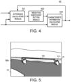
- Fig. 4 is a functional block diagram illustrating a configuration of the characteristic information updating module.
- the characteristic information updating module 42 may include a difference calculation module 421, a weighting coefficient setting module 422, and a characteristic information calculation module 423.
- the difference calculation module 421 may calculate a difference between the characteristic information and the measurement information.
- the difference calculation module 421 may calculate the difference between the initial characteristic information and the measurement information corresponding to this timing.
- the characteristic information updated by the characteristic information calculation module 423 is fed back to the difference calculation module 421, the difference calculation module 421 may calculate a difference between the fed-back characteristic information and the measurement information corresponding to the fed-back timing.
- the measurement information corresponding to the timing illustrated here indicates, for example, the measurement information acquired at a time point immediately after that timing.
- the difference calculation module 421 may calculate a difference between the initial characteristic information or the fed-back characteristic information (the characteristic information before updating) and the measurement information, for every plurality of measurement information.
- the difference calculation module 421 may output the difference for each measurement information to the weighting coefficient setting module 422.
- the weighting coefficient setting module 422 may set a weighting coefficient according to the difference for each measurement information.
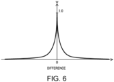
- Fig. 6 is a graph illustrating one example of an example setting of the weighting coefficient. As illustrated in Fig. 6 , the weighting coefficient may be set so that a weighting coefficient w becomes smaller as an absolute value of the difference becomes larger.
- the weighting coefficient setting module 422 may output the weighting coefficient w for each measurement information to the characteristic information calculation module 423.
- the measurement information and the weighting coefficient w may be inputted into the characteristic information calculation module 423.
- the characteristic information calculation module 423 may calculate the characteristic information using the measurement information and the weighting coefficient w for this measurement information.
- the characteristic information calculation module 423 may normalize the weighting coefficient w.
- the normalization as used herein is resetting the weighting coefficient w so that the sum total of adding up all the weighting coefficients becomes 1. Note that this normalization processing may be performed by the weighting coefficient setting module 422.
- the characteristic information calculation module 423 may multiply the measurement information by the normalized weighting coefficient w.
- the characteristic information calculation module 423 may output a result of summing the measurement information by which the weighting coefficient w was multiplied, as new characteristic information (characteristic information after updating).
- the updated characteristic information may be generated by the addition of the measurement information which used the ranging result. Therefore, the accumulation of the error by repeating the update is suppressed.
- the measurement information may be multiplied by the weighting coefficient.
- the weighting coefficient may be set so that its influence to the updated characteristic information becomes smaller as the difference from the characteristic information before the update becomes larger. Therefore, the updated characteristic information becomes highly precise to the actual characteristic information, because the influence of the error contained in the characteristic information before updating is reduced.
- the ship navigation assistance device 10 is capable of generating the characteristic information which is highly precise to the actual characteristic information, while suppressing the updating error.
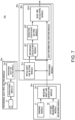
- Fig. 7 is a functional block diagram illustrating one example of a concrete example application of the configuration of the ship navigation assistance device according to one embodiment of the present disclosure. Note that Fig. 7 is fundamentally similar to a drawing which combines Fig. 1, Fig. 2, Fig. 3 , and Fig. 4 , and differs in that the object, the characteristic information, etc. are embodied. Below, only modules which need additional explanation are described, and description of modules which can be understood from the above explanation is omitted.
- Fig. 8 is a view illustrating a concept of updating the quay line.
- Figs. 9(A), 9(B), and 9(C) are views illustrating an update state of the quay line.
- the ship navigation assistance device 10e may include a provisional quay information setting module 20e, a measurement module 30e, and a processing module 40e.
- the provisional quay information setting module 20e corresponds to the above-described provisional initial information setting module 20.
- the measurement module 30e corresponds to the measurement module 30.
- the processing module 40e corresponds to the processing module 40.
- the provisional quay information setting module 20e may include the camera 21, the operational input interface 22, and a provisional quay line setting module 23e.
- the provisional quay line setting module 23e corresponds to the provisional initial information setting module 23, and may set a provisional quay line (see the provisional quay line 920 in Fig. 5 described above) using the operational input result.
- the provisional quay line setting module 23e may output the provisional quay line to the processing module 40e.
- the measurement module 30e may include the ranging module 31, the attitude measurement module 32, and a measurement line generating module 33e.
- the measurement line generating module 33e corresponds to the measurement information generating module 33, and may generate a straight measurement line using the plurality of characteristic points obtained by the ranging and the attitude of a ship 100.
- the measurement line may be represented by a distance ⁇ from a reference point (for example, a sensor position) 111 of the ship 100, and a direction ⁇ of the measurement line on the basis of the position of the ship 100. As illustrated in Fig.
- the distance ⁇ may be a length of a perpendicular line which is drawn from the ship 100 and is perpendicular to the measurement line, and the direction ⁇ may be an angle formed between a reference direction in a given coordinate system and an extending direction of the perpendicular line.
- the measurement line generating module 33e may output the measurement line to the processing module 40e.
- the processing module 40e may include an initial quay line setting module 41e and a quay information updating module 42e.
- the initial quay line setting module 41e corresponds to the initial characteristic information setting module 41
- the quay information updating module 42e corresponds to the characteristic information updating module 42.
- the quay information updating module 42e may include the difference calculation module 421, the weighting coefficient setting module 422, and a quay line calculation module 423e.
- the quay line calculation module 423e corresponds to the characteristic information calculation module 423.
- the provisional quay line and the measurement line may be inputted into the initial quay line setting module 41e. If the number of measurement lines is one, the initial quay line setting module 41e may set this measurement line as the initial quay line. If the number of measurement lines is two or more, the initial quay line setting module 41e may set a maximum likelihood measurement line among the plurality of measurement lines as the initial quay line. For example, the initial quay line setting module 41e may set the maximum likelihood measurement line, for example, as a measurement line with parameters most similar to the parameters (the distance ⁇ and the direction ⁇ ) of the provisional quay line. The initial quay line setting module 41e may output the initial quay line to the quay information updating module 42e.
- the initial quay line and the measurement line may be inputted into the difference calculation module 421 of the quay information updating module 42e.
- the difference calculation module 421 may calculate a difference between each of the measurement lines and the initial quay line.
- the difference calculation module 421 may calculate the difference for each parameter. That is, the difference calculation module 421 may calculate, for one measurement line, a difference ⁇ of the distance ⁇ and a difference ⁇ of the direction ⁇ , with respect to the initial quay line.
- a plurality of measurement lines 931(T1), 932(T1), 933(T1), and 934(T1) measured at a timing T1 immediately after that may be obtained.
- the measurement line 931(T1) may be obtained at the timing T1, and may be generated from a plurality of characteristic points 81(T1) lined up straight.
- the measurement line 932(T1) may be obtained at the timing T1, and may be generated from a plurality of characteristic points 82(T1) lined up straight.
- the measurement line 933(T1) may be obtained at the timing T1, and may be generated from a plurality of characteristic points 83(T1) lined up straight.
- the measurement line 934(T1) may be obtained at the timing T1, and may be generated from a plurality of characteristic points 84(T1) lined up straight.
- the difference calculation module 421 may output the difference for every measurement line to the weighting coefficient setting module 422.
- the difference calculation module 421 may calculate a difference ⁇ 1(T1) between the distance ⁇ 1(T1) of the measurement line 931(T 1), and a distance ⁇ (T0) of the last quay line 920(T0).
- the difference calculation module 421 may calculate a difference ⁇ 1(T1) between the direction ⁇ 1(T1) of the measurement line 931(T1) and the direction ⁇ (T0) of the last quay line 920(T0).
- the difference calculation module 421 may calculate a difference ⁇ 2(T1) and a difference ⁇ 2(T1) for the measurement line 932(T1), calculate a difference ⁇ 3(T1) and a difference ⁇ 3(T1) for the measurement line 933(T1), and calculate a difference ⁇ 4(T1) and a difference ⁇ 4(T1) for the measurement line 934(T1). Then, the difference calculation module 421 may output these differences to the weighting coefficient setting module 422.
- the weighting coefficient setting module 422 may set the weighting coefficients according to the differences. In more detail, the weighting coefficient setting module 422 may set a first weighting coefficient wp for the distance ⁇ according to the difference ⁇ of the distance ⁇ . The weighting coefficient setting module 422 may set a second weighting coefficient w ⁇ for the direction ⁇ according to the difference ⁇ of the direction ⁇ . The weighting coefficient setting module 422 may output the first weighting coefficient wp and the second weighting coefficient w ⁇ to the quay line calculation module 423e.
- the quay line calculation module 423e may normalize the first weighting coefficient wp using the number of measurement lines to be added, respectively.
- the quay line calculation module 423e may normalize the second weighting coefficient w ⁇ using the number of measurement lines to be added, respectively.
- the quay line calculation module 423e may multiply, for every measurement line, the distance ⁇ by the normalized first weighting coefficient wp, and add up these multiplied values. For example, for the example of Fig. 8 , the quay line calculation module 423e may multiply the distance ⁇ 1(T1) of the measurement line 931(T1) by the first weighting coefficient w ⁇ 1, multiply the distance ⁇ 2(T1) of the measurement line 932(T1) by the first weighting coefficient wp2, multiply the distance p3(Tl) of the measurement line 933(T1) by the first weighting coefficient wp3, multiply the distance ⁇ 4(T1) of the measurement line 934(T1) by the first weighting coefficient wp4, and add up these multiplied values to calculate the distance ⁇ (T1) of the quay line 920(T1) at the timing T1.
- the quay line calculation module 423e may multiply, for every measurement line, the direction ⁇ by the normalized second weighting coefficient w ⁇ , and add up these multiplied values. For example, for the example of Fig. 8 , the quay line calculation module 423e may multiply the direction ⁇ 1(T1) of the measurement line 931(T1) by the second weighting coefficient w ⁇ 1, multiply the direction ⁇ 2(T1) of the measurement line 932(T1) by the second weighting coefficient w ⁇ 2, multiply the direction ⁇ 3(T1) of the measurement line 933(T1) by the second weighting coefficient w ⁇ 3, multiply the direction ⁇ 4(T1) of the measurement line 934(T1) by the second weighting coefficient w ⁇ 4, and add up these multiplied values to calculate the direction ⁇ (T1) of the quay line 920(T 1) at the timing T 1.
- the quay line 920 may be updated sequentially as illustrated in Figs. 9(A), 9(B), and 9(C) .
- the quay line 920(T1) at the timing T1 may be generated based on the measurement lines 931(T1), 932(T1), 933(T1), and 934(T1) at the timing T1, and the quay line 920(T0) at the last timing T0, and the quay line 920 may be updated.
- the quay line 920(T1) at the timing T1 may be generated based on the measurement lines 931(T1), 932(T1), 933(T1), and 934(T1) at the timing T1, and the quay line 920(T0) at the last timing T0, and the quay line 920 may be updated.
- Fig. 9(A) the quay line 920(T1) at the timing T1 may be generated based on the measurement lines 931(T1), 932(T1), 933(
- a quay line 920(T2) at a timing T2 may be generated based on measurement lines 931(T2), 932(T2), 933(T2), and 934(T2) at the timing T2, and the quay line 920(T1) at the last timing T1, and the quay line 920 may be updated.
- a quay line 920(T3) at a timing T3 may be generated based on measurement lines 931(T3), 932(T3), 933(T3), and 934(T3) at the timing T3, and the quay line 920(T2) at the last timing T2, and the quay line 920 may be updated.
- the ship navigation assistance device 10e can update the quay line 920 sequentially, and can suppress the accumulation of the updating error.
- the quay line 920 is updated using the ranging result at each timing, even if the ship 100 is moved. Therefore, the influence of the error due to the movement can also be reduced.
- each processing may be performed by an individual functional module.
- the above processing can be implemented by being stored as a ship navigation assistance program and being executed by a processing unit.
- the processing may be executed according to the flow illustrated in each of the following drawings. Note that, in the concrete contents of the processing in the following description, the detailed description of the above-described contents is omitted.
- Figs. 10(A) and 10(B) are flowcharts illustrating outline processings of the ship navigation assistance method.
- Fig. 10(B) illustrates a case where the processing of Fig. 10(A) is set for a more concrete object (quay).
- the processing unit (the ship navigation assistance device) may set the initial characteristic information on the object (S11).
- the processing unit may generate the measurement information on the area including the object (S12).
- the processing unit may update the characteristic information by calculating new characteristic information from the initial information on the characteristic information on the object or the characteristic information before updating, and the measurement information (S13).
- the processing unit may set the initial quay line (S11e).
- the processing unit may generate the measurement line of the area including the quay (S12e).
- the processing unit may update the quay line by calculating a new quay line from the initial quay line or the quay line before updating, and the measurement line (S 13e).
- Fig. 11(A) is a flowchart illustrating a concrete process flow of the update of the characteristic information illustrated in Fig. 10(A) .
- Fig. 11(B) is a flowchart illustrating a concrete process flow of the update of the quay line illustrated in Fig. 10(B) .
- the processing unit may acquire the characteristic information before updating, which includes the initial characteristic information (S31).
- the processing unit may acquire a plurality of measurement information (S32).
- the processing unit may calculate a difference between the measurement information and the characteristic information (S33).
- the processing unit may set, for each measurement information, the weighting coefficient according to the difference (S34).
- the processing unit may calculate the updated characteristic information using the weighting coefficient and the measurement information (S35).
- the processing unit may acquire the quay line before updating, which includes the initial quay line (S31e).
- the processing unit may acquire a plurality of measurement lines (S32e).
- the processing unit may calculate a difference between the measurement line and the quay line (S33e).
- the processing unit may set, for every measurement line, the weighting coefficient according to the difference (S34e).
- the processing unit may calculate the updated quay line using the weighting coefficient and the measurement line (S35e).
- Fig. 12 is a flowchart illustrating another concrete process flow of the update of the characteristic information.
- the processing illustrated in Fig. 12 differs from the processing illustrated in Fig. 11(A) in an adjustment processing of the weighting coefficient.
- Other processings illustrated in Fig. 12 are similar to the processing illustrated in Fig. 11(A) , and description of the similar modules is omitted.
- the processing unit may adjust the weighting coefficient according to the traveling state of the ship (S391). For example, the processing unit may reduce the reduction of the weight according to the difference as the ship becomes farther from the object. Further, the processing unit may reduce the reduction of the weight according to the difference as the traveling speed of the ship is faster (in more detail, for example, as the approaching speed to the object is faster). Note that these contents of the adjustment are examples, and, for example, the reduction of the weight may be reduced as the traveling state has a larger error contained in the ranging result and the measurement information.
- the ship navigation assistance devices 10 and 10e can update the characteristic information (for example, the quay line) with higher accuracy.
- Fig. 13 is a flowchart illustrating another concrete process flow of the update of the characteristic information.
- the processing illustrated in Fig. 13 differs from the processing illustrated in Fig. 11(A) in a selection processing of the measurement information.
- Other processings illustrated in Fig. 13 are similar to the processing illustrated in Fig. 11(A) , and description of the similar modules is omitted.
- the processing unit may exclude the measurement information of which the difference does not satisfy the condition (S392).
- This condition may be, for example, that the difference exceeds a threshold, in more detail, that the difference ⁇ of the distance ⁇ exceeds a threshold for the distance, or that the difference ⁇ of the direction ⁇ exceeds a threshold for the direction.
- the ship navigation assistance devices 10 and 10e can eliminate, from the calculation of the characteristic information, the measurement information which has a bad influence to the calculation of the characteristic information (clearly far from the object, clearly different in shape, etc.).
- the characteristic information (quay line) can be updated continuously, for example, even if the measurement information (measurement line) is hardly acquired at a certain timing.
- the ship navigation assistance devices 10 and 10e may adopt an averaging processing of the characteristic information (e.g., a moving average).
- the characteristic information calculation module 423 of the processing module 40 may calculate the updated characteristic information by carrying out the averaging processing with weighting of the characteristic information before updating and the calculated characteristic information.
- the quay line calculation module 423e of the processing module 40e may calculate the updated quay line by carrying out the averaging processing with weighting of the quay line before updating and the calculated quay line.
- the converging speed of the characteristic information by the update becomes slower by increasing the weight of the characteristic information (quay line) before updating
- the influence by the error of the measurement information (measurement line) can be reduced.
- the ship is a large ship or a vessel, this is especially useful because the influence by the error is more important than the converging speed.
- Fig. 14(A) is a flowchart illustrating processing of the ship navigation assistance method including generation of the navigation assistance information.
- Fig. 14(B) illustrates a case where the processing of Fig. 14(A) is set for a more concrete object (quay). Note that the processing illustrated in Fig. 14(A) differs from the processing illustrated in Fig. 10(A) in that generation processing of navigation assistance information is added, and the processing illustrated in Fig. 14(B) differs from the processing illustrated in Fig.
- FIG. 14(A) in that generation of a quay line distance is added.
- Other processings of Figs. 14(A) and 14(B) are similar to the processings illustrated in Figs. 10(A) and 10(B) , respectively, and description of the similar modules is omitted.
- the processing unit may generate the navigation assistance information based on the characteristic information (S14).
- the processing unit may generate the quay line distance based on the calculated (updated) quay line (S14e).
- the quay line distance may be obtained based on the distance ⁇ of the quay line, for example.
- the quay line may be calculated and updated. However, it is also possible to calculate and update other characteristic information related to the quay. Below, as other characteristic information, the quay reference point is calculated and updated. Note that the quay reference point is a reference point when the ship 100 docks, which is located on the quay line.
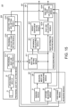
- Fig. 15 is a functional block diagram illustrating a configuration of the ship navigation assistance device in which the quay line and the quay reference point are calculated and updated.
- the ship navigation assistance device 10f illustrated in Fig. 15 differs from the ship navigation assistance device 10e illustrated in Fig. 7 in that a provisional quay reference point setting module 232f, a quay reference point information setting module 233f, a positioning module 34, and a quay reference point calculation module 424f are further provided.
- Other configurations of the ship navigation assistance device 10f are similar to those of the ship navigation assistance device 10e, and description of the similar modules is omitted.
- the ship navigation assistance device 10f may include a provisional quay information setting module 20f, a measurement module 30f, and a processing module 40f.
- the provisional quay information setting module 20f may include the camera 21, the operational input interface 22, a provisional quay line setting module 231f, the provisional quay reference point setting module 232f, and the quay reference point information setting module 233f.
- the provisional quay line setting module 231f may have a similar function to the provisional quay line setting module 23e.
- the measurement module 30f may include the ranging module 31, the attitude measurement module 32, a measurement line generating module 33f, and the positioning module 34.
- the measurement line generating module 33f may have a similar function to the measurement line generating module 33e.
- the positioning module 34 may have, for example, a positioning function of the GNSS, which measures the position of the ship 100.
- the processing module 40f may include an initial quay line setting module 41f and a quay information updating module 42f.
- the initial quay line setting module 41f may have a similar function to the initial quay line setting module 41e.
- the quay information updating module 42f may include the difference calculation module 421, the weighting coefficient setting module 422, a quay line calculation module 423f, and the quay reference point calculation module 424f.
- the quay line calculation module 423f may have a similar function to the quay line calculation module 423e.
- the update of the quay line is similar to that of the above-described ship navigation assistance device 10e, and description thereof is omitted.
- the provisional quay reference point setting module 232f may set the provisional quay reference point using the operational input result. For example, the provisional quay reference point setting module 232f may detect coordinates of an operated position on a screen, and set them as the provisional quay reference point. The provisional quay reference point setting module 232f may output the provisional quay reference point to the quay reference point information setting module 233f.
- the quay reference point information setting module 233f may calculate a direction ⁇ of the provisional quay reference point on the basis of the ship 100 using the provisional quay reference point, and the attitude of the ship 100 and the position of the ship 100. Then, the quay reference point information setting module 233f may set the provisional quay reference point including this direction ⁇ as the initial quay reference point. The quay reference point information setting module 233f may output the direction ⁇ of the initial quay reference point on the basis of the ship 100, which is indicated using the direction ⁇ , to the quay reference point calculation module 424f of the processing module 40f.
- the updated quay line, the initial quay reference point, the position of the ship 100, and the attitude of the ship 100 may be inputted into the quay reference point calculation module 424f.
- the quay reference point calculation module 424f may calculate a variation ⁇ of the direction ⁇ using a variation in the position and a variation in the attitude of the ship 100 from the updating timing of the previous quay reference point.
- the quay reference point calculation module 424f may correct the direction ⁇ of the initial quay reference point or the direction ⁇ before updating by the variation ⁇ , and update the direction ⁇ .
- the quay reference point calculation module 424f may calculate an intersection between a straight line indicated by the updated direction ⁇ , and the updated quay line.
- the quay reference point calculation module 424f may calculate coordinates of the updated quay reference point based on the distance between the intersection and the ship 100, and the position of the ship 100. Thus, the quay reference point calculation module 424f may update the quay reference point.
- Figs. 16(A), 16(B), and 16(C) are views illustrating an update state of the quay line and the quay reference point.
- the initial quay line 920(T0) may be updated to the quay line 920(T1), and in connection with this, an initial quay reference point 929(T0) may be updated to a quay reference point 929(T1).
- the update of the quay reference point in this case i.e., a direction ⁇ (T1) of the quay reference point 929(T1) may be obtained by correcting a direction ⁇ (T0) of the initial quay reference point 929(T0) by a direction variation ⁇ v01 due to the change in the position of the ship, and a direction variation ⁇ d01 due to the change in the attitude.
- the positional coordinates of the quay reference point 929(T1) can also be calculated by obtaining the direction ⁇ (T1) of this quay reference point 929(T 1), and the quay line 920(T 1).
- the quay line 920(T1) may be updated to the quay line 920(T2), and in connection with this, the quay reference point 929(T 1) may be updated to a quay reference point 929(T2).
- the update of the quay reference point in this case, i.e., a direction ⁇ (T2) of the quay reference point 929(T2) may be obtained by correcting the direction ⁇ (T1) of the quay reference point 929(T 1) by a direction variation ⁇ v12 due to the change in the position of the ship and a direction variation ⁇ d12 due to the change in the attitude.
- the positional coordinates of the quay reference point 929(T2) can also be calculated by obtaining the direction ⁇ (T2) of this quay reference point 929(T2), and the quay line 920(T2).
- the quay line 920(T2) may be updated by the quay line 920(T3), and in connection with this, the quay reference point 929(T2) may be updated to a quay reference point 929(T3).
- the update of the quay reference point in this case, i.e., a direction ⁇ (T3) of the quay reference point 929(T3) may be obtained by correcting the direction ⁇ (T2) of the quay reference point 929(T2) by a direction variation ⁇ v23 due to the change in the position of the ship and a direction variation ⁇ d23 due to the change in the attitude.
- the positional coordinates of the quay reference point 929(T3) can also be calculated by obtaining the direction ⁇ (T3) of this quay reference point 929(T3), and the quay line 920(T3).
- each processing may be executed by the individual functional module.
- the above processing can be realized by being stored as a ship navigation assistance program and being executed by a processing unit.
- the processing may be executed according to the flow illustrated in each of the following drawings. Note that, in the concrete contents of the processing in the following description, the detailed description of the above-described contents is omitted.
- Fig. 17 is a flowchart illustrating outline processing of a method of updating the quay line and the quay reference point.
- the processing unit (the ship navigation assistance device) may set the initial quay line and the initial quay reference point (S11f).
- the processing unit may generate an actual quay line, and a measurement line of the area including an actual quay reference point (S 12f).
- the processing unit may update the quay line using the measurement line (S13f).
- the processing unit may update the quay reference point using the position and the attitude of the ship 100, and the updated quay line (S 14f).
- Fig. 18 is a flowchart illustrating a method of updating the quay reference point.
- the processing unit (the ship navigation assistance device) may acquire the updated quay line (S41).
- the processing unit may acquire a direction of the quay reference point before updating (for example, the quay reference point on the basis of the ship 100) (S42).
- the processing unit may acquire a traveled distance (a variation in the position) and a variation in the attitude of the ship 100 (S43).
- the processing unit may update the quay reference point (direction) using the direction of the quay reference point before updating, and the traveled distance (the variation in the position) and the variation in the attitude of the ship 100 (S44).
- the processing unit may update the quay reference point (positional coordinates) using the updated quay reference point (direction) and the updated quay line (S45).
- the ship navigation assistance device 10f can suppress the error in the update of the quay reference point, as well as the update of the quay line.
- the provisional initial information may be set by the user's operational input.
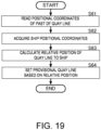
- Fig. 19 is a flowchart illustrating a processing which sets the provisional initial information based on the positional coordinates of the past of the characteristic information on the object.
- the characteristic information on the object is the quay line
- the provisional initial information is the provisional quay line.
- the processing unit may store the positional coordinates of the past of the quay line.
- the processing unit may read the positional coordinates of the past of the quay line (S61).
- the processing unit may acquire the positional coordinates of the ship (which anchors or docks to the object) (S62).
- the acquisition of the positional coordinates of the ship may be realizable, for example, by using the above-described positioning technique of the GNSS signals.
- the processing unit may calculate a relative position of the quay line with respect to the ship by using these positional coordinates (S63).
- the processing unit may set the provisional quay line based on the relative position (S64). For example, the processing unit may convert the relative position into a vector quantity set by a distance and a direction on the basis of the ship, and set the provisional quay line.
- the positional coordinates of the past of the quay line may be used.
- the initial information is set based on the measurement information, while using the provisional initial information as the reference.
- the provisional initial information may be set as the initial information as it is.
- the provisional initial information since the provisional initial information is less in the errors, it may be used for the initial information as it is.
- the example in which the quay is the object is illustrated.
- the object is a pier, another ship, etc., which is an object to which the ship anchors, the above-described configuration and processing are applicable.
Landscapes
- Engineering & Computer Science (AREA)
- Radar, Positioning & Navigation (AREA)
- Remote Sensing (AREA)
- Physics & Mathematics (AREA)
- General Physics & Mathematics (AREA)
- Combustion & Propulsion (AREA)
- Chemical & Material Sciences (AREA)
- Mechanical Engineering (AREA)
- Ocean & Marine Engineering (AREA)
- Automation & Control Theory (AREA)
- Electromagnetism (AREA)
- Computer Networks & Wireless Communication (AREA)
- Aviation & Aerospace Engineering (AREA)
- Navigation (AREA)
Abstract
Description
- The present disclosure relates to a ship navigation assistance technology which is used when anchoring a ship.
- In
Patent Document 1, a docking assistance device for a ship is disclosed. The docking assistance device disclosed inPatent Document 1 uses a distance measurement means to measure a distance between the ship and a plurality of points of a quay. - [Patent Document 1]
JP5000244B2 - However, the distance measured by the distance measurement means as described in the conventional technology contains an error. In addition, this error occurs in every measurement of the distance, and increases sequentially.
- Thus, one purpose of the present disclosure is to suppress an error which occurs in movement, such as in anchoring a ship.
- A ship navigation assistance device according to the present disclosure includes a measurement module and a characteristic information updating module. The measurement module acquires measurement information on an object using a ranging result of an area including the object that is an anchorage target of a ship. The characteristic information updating module updates characteristic information on the object using initial characteristic information on the object or characteristic information before updating on the object, and the measurement information.
- According to this configuration, the ranging result is reflected on characteristic information after updating.
- According to the present disclosure, the error which occurs in movement, such as in anchoring a ship, can be suppressed.
-
-
Fig. 1 is a functional block diagram illustrating a configuration of a ship navigation assistance device according to one embodiment of the present disclosure. -
Fig. 2 is a functional block diagram illustrating a configuration of a provisional initial information setting module. -
Fig. 3 is a functional block diagram illustrating a configuration of a measurement module. -
Fig. 4 is a functional block diagram illustrating a configuration of a characteristic information updating module. -
Fig. 5 is a view illustrating one example of a method of specifying provisional initial information. -
Fig. 6 is a graph illustrating one of the example settings of a weighting coefficient. -
Fig. 7 is a functional block diagram illustrating one of the concrete example applications of the configuration of the ship navigation assistance device according to one embodiment of the present disclosure. -
Fig. 8 is a view illustrating an updating concept of a quay line. -
Figs. 9(A), 9(B), and 9(C) are views illustrating an update state of the quay line. -
Figs. 10(A) and 10(B) are flowcharts illustrating outline processing of a ship navigation assistance method. -
Fig. 11(A) is a flowchart illustrating a concrete process flow of the update of the characteristic information illustrated inFig. 10(A) , andFig. 11(B) is a flowchart illustrating a concrete process flow of the update of the quay line illustrated inFig. 10(B) . -
Fig. 12 is a flowchart illustrating another concrete process flow of the update of the characteristic information. -
Fig. 13 is a flowchart illustrating another concrete process flow of the update of the characteristic information. -
Fig. 14(A) is a flowchart illustrating processing of the ship navigation assistance method including generation of navigation assistance information, andFig. 14(B) illustrates a case where the processing ofFig. 14(A) is set to a more concrete object (quay). -
Fig. 15 is a functional block diagram illustrating a configuration of the ship navigation assistance device in an aspect in which the quay line and a quay reference point are calculated and updated. -
Figs. 16(A), 16(B), and 16(C) are views illustrating an update state of the quay line and the quay reference point. -
Fig. 17 is a flowchart illustrating outline processing of a method of updating the quay line and the quay reference point. -
Fig. 18 is a flowchart illustrating the method of updating the quay reference point. -
Fig. 19 is a flowchart illustrating a processing which sets the provisional initial information based on positional coordinates of the past of the characteristic information on the object. - A ship navigation assistance technology according to one embodiment of the present disclosure is described with reference to the drawings.
Fig. 1 is a functional block diagram illustrating a configuration of a ship navigation assistance device according to one embodiment of the present disclosure.Fig. 2 is a functional block diagram illustrating a configuration of a provisional initial information setting module.Fig. 3 is a functional block diagram illustrating a configuration of a measurement module. - As illustrated in
Fig. 1 , the shipnavigation assistance device 10 may include a provisional initialinformation setting module 20, ameasurement module 30, and aprocessing module 40. The shipnavigation assistance device 10 may be realizable, for example, by a memory device which stores a program (ship navigation assistance program) for implementing a ship navigation assistance method, and a processing unit, such as a CPU, for executing the ship navigation assistance program, except for optical-system modules and radio-wave-system modules. Further, the modules of the memory device and the processing unit may also be realized by an IC etc. in which the navigation assistance program is incorporated. - The provisional initial
information setting module 20 may accept a specification of provisional initial information for characteristic information on an object to which a ship anchors or docks (docks to a pier). The provisional initialinformation setting module 20 may output the provisional initial information to theprocessing module 40. For example, the object may be a quay (wall), the characteristic information may be a vector quantity of a quay line, or positional coordinates of a quay reference point, and the provisional initial information may be a provisional quay line (vector quantity) and a provisional quay reference point (positional coordinates). - The
measurement module 30 may range or measure a distance to an area including the object to which the ship anchors or docks (docks to a pier). Themeasurement module 30 may acquire measurement information on the object using the ranging result. Themeasurement module 30 may output the measurement information to theprocessing module 40. For example, the measurement information may be a vector quantity of a line segment (straight line). - The
processing module 40 may include an initial characteristicinformation setting module 41 and a characteristicinformation updating module 42. The provisional initial information may be inputted into the initial characteristicinformation setting module 41. The measurement information may be inputted into the initial characteristicinformation setting module 41 and the characteristicinformation updating module 42. - The initial characteristic
information setting module 41 may set initial characteristic information using the provisional initial information and the measurement information. The initial characteristic information may be, for example, an initial quay line (vector quantity) and initial a quay reference point (positional coordinates). - In detail, for example, if the number of measurement information on the object is one, the initial characteristic
information setting module 41 may set this measurement information as the initial characteristic information. If there are a plurality of measurement information on the object, the initial characteristicinformation setting module 41 may set the initial characteristic information based on the plurality of measurement information. For example, the initial characteristicinformation setting module 41 may detect measurement information (maximum likelihood measurement information) of which the position and the direction to the ship are most similar to the provisional initial information, among the plurality of measurement information. The initial characteristicinformation setting module 41 may set the maximum likelihood measurement information as the initial characteristic information. By performing such processing, the shipnavigation assistance device 10 can suppress an error of the initial characteristic information, rather than when a user manually inputting the initial characteristic information. The initial characteristicinformation setting module 41 may output the initial characteristic information to the characteristicinformation updating module 42. - The characteristic
information updating module 42 may update the characteristic information using the measurement information. For example, the characteristicinformation updating module 42 may update it to new characteristic information using the measurement information at a time point substantially the same as the setting timing of the initial characteristic information. Further, thereafter, the characteristicinformation updating module 42 may sequentially update the characteristic information using the acquired measurement information. Note that more detailed configuration and processing of the characteristicinformation updating module 42 will be described later. - By performing such processing, the characteristic information to be updated may be set based on the measurement information for every update. Therefore, even if the characteristic information is sequentially updated, an increase in the error can be suppressed. Therefore, for example, the ship
navigation assistance device 10 can suppress an error which is contained in information to be acquired when the ship moves to the object (e.g., a spatial relationship, a distance, and a direction between the ship and the object). As a more concrete example, for example, it can suppress the errors contained in the distance and the direction between the ship and the quay line or the quay reference point in movement (docking), such as anchoring the ship. - As illustrated in
Fig. 2 , the provisional initialinformation setting module 20 may include acamera 21, anoperational input interface 22, and a provisional initialinformation setting module 23. - The
camera 21 may be connected to theoperational input interface 22. Thecamera 21 may be, for example, a monocular camera, which images an area including the object (for example, a quay). Thecamera 21 may output the captured image to theoperational input interface 22. - The
processing input interface 22 may be, for example, realized by a touch panel. Theprocessing input interface 22 may display the inputted image. Theprocessing input interface 22 may accept an operational input from a user, and detect an operated position on the image (a locus of the operation). Theprocessing input interface 22 may output the operated position (the locus of the operation) to the provisional initialinformation setting module 23. - The provisional initial
information setting module 23 may convert the operated position (the locus of the operation) into a vector quantity in a three-dimensional coordinate system which is set to the image, and set up it as provisional initial information. The provisional initialinformation setting module 23 may output the provisional initial information to theprocessing module 40. -
Fig. 5 is a view illustrating one example of a method of specifying the provisional initial information. As illustrated inFig. 5 , the image including aquay 90 which is the object may be displayed on a display screen. When the user operates the touch panel with his/her finger so as to follow anactual quay line 910 displayed on the screen, theoperational input interface 22 may detect the locus of the operation (a locus corresponding to aprovisional quay line 920 inFig. 5 ). In more detail, theoperational input interface 22 may detect a group of pixels (a group of coordinates of the pixels) which are operated with the finger in the image, as the locus. Theprocessing input interface 22 may output this locus to the provisional initialinformation setting module 23. - The provisional initial
information setting module 23 may set this locus as theprovisional quay line 920. Theprovisional quay line 920 may be expressed, for example, by a vector quantity which is set based on a direction and a distance on the basis of the position of the ship. Theprovisional quay line 920 may correspond to the provisional initial information. The provisional initialinformation setting module 23 may output theprovisional quay line 920 to the initial characteristicinformation setting module 41 of theprocessing module 40. - As illustrated in
Fig. 3 , themeasurement module 30 may include a rangingmodule 31, anattitude measurement module 32, and a measurementinformation generating module 33. - The ranging
module 31 may be realized by a LIDAR, for example. Note that the rangingmodule 31 may be a LADAR, or other distance measuring equipment, such as optical-based or radio-wave-based equipment. The rangingmodule 31 may perform a three-dimensional ranging for the area including the object to detect a plurality of characteristic points. The rangingmodule 31 may output the plurality of characteristic points to the measurementinformation generating module 33. - The
attitude measurement module 32 may be, for example, realized by an attitude sensor provided to the ship. Note that the attitude sensor may use a positioning technique of GNSS signals, or may use an inertia sensor. Further, the attitude sensor may combine the positioning technique of the GNSS signals and the inertia sensor. When the positioning technique of the GNSS signals is used, the position (positional coordinates) of the ship can also be measured. Further, when the positioning technique of the GNSS signals is used, the attitude can be measured with high precision in an open-sky situation, like on the sea. Theattitude measurement module 32 may measure the attitude of the ship. Theattitude measurement module 32 may output the attitude of the ship to the measurementinformation generating module 33. - The measurement
information generating module 33 may convert (project) the plurality of characteristic points obtained by three-dimensional coordinates into a two-dimensional coordinate system on a horizontal plane. Here, the measurementinformation generating module 33 can convert the plurality of characteristic points in the three-dimensional coordinate system into the two-dimensional coordinate system on the horizontal plane with high precision by utilizing the attitude of the ship, for example, even if the ship rolls or pitches. - The measurement
information generating module 33 may apply a given conversion process (for example, a Hough conversion process) to the plurality of characteristic points disposed at the two-dimensional coordinates on the horizontal plane to generate the measurement information. The measurementinformation generating module 33 may output the generated measurement information to the initial characteristicinformation setting module 41 and the characteristicinformation updating module 42 of theprocessing module 40. Note that the processing for converting the plurality of characteristic points obtained by the three-dimensional coordinates into the two-dimensional coordinate system on the horizontal plane can be omitted. - The
processing module 40 may include the initial characteristicinformation setting module 41 and the characteristicinformation updating module 42, as described above. The initial characteristicinformation setting module 41 is described above, and therefore, explanation thereof will be omitted below. The initial characteristicinformation setting module 41 may set the initial characteristic information using the provisional initial information and the measurement information, and output it to the characteristicinformation updating module 42. -
Fig. 4 is a functional block diagram illustrating a configuration of the characteristic information updating module. As illustrated inFig. 4 , the characteristicinformation updating module 42 may include adifference calculation module 421, a weightingcoefficient setting module 422, and a characteristicinformation calculation module 423. - The
difference calculation module 421 may calculate a difference between the characteristic information and the measurement information. In more detail, when the initial characteristic information is inputted into thedifference calculation module 421, thedifference calculation module 421 may calculate the difference between the initial characteristic information and the measurement information corresponding to this timing. Further, when the characteristic information updated by the characteristicinformation calculation module 423 is fed back to thedifference calculation module 421, thedifference calculation module 421 may calculate a difference between the fed-back characteristic information and the measurement information corresponding to the fed-back timing. Note that the measurement information corresponding to the timing illustrated here indicates, for example, the measurement information acquired at a time point immediately after that timing. - When a plurality of measurement information are acquired, the
difference calculation module 421 may calculate a difference between the initial characteristic information or the fed-back characteristic information (the characteristic information before updating) and the measurement information, for every plurality of measurement information. Thedifference calculation module 421 may output the difference for each measurement information to the weightingcoefficient setting module 422. - The weighting
coefficient setting module 422 may set a weighting coefficient according to the difference for each measurement information.Fig. 6 is a graph illustrating one example of an example setting of the weighting coefficient. As illustrated inFig. 6 , the weighting coefficient may be set so that a weighting coefficient w becomes smaller as an absolute value of the difference becomes larger. The weightingcoefficient setting module 422 may output the weighting coefficient w for each measurement information to the characteristicinformation calculation module 423. - The measurement information and the weighting coefficient w may be inputted into the characteristic
information calculation module 423. The characteristicinformation calculation module 423 may calculate the characteristic information using the measurement information and the weighting coefficient w for this measurement information. In more detail, the characteristicinformation calculation module 423 may normalize the weighting coefficient w. The normalization as used herein is resetting the weighting coefficient w so that the sum total of adding up all the weighting coefficients becomes 1. Note that this normalization processing may be performed by the weightingcoefficient setting module 422. - The characteristic
information calculation module 423 may multiply the measurement information by the normalized weighting coefficient w. The characteristicinformation calculation module 423 may output a result of summing the measurement information by which the weighting coefficient w was multiplied, as new characteristic information (characteristic information after updating). - By such a configuration and processing, the updated characteristic information may be generated by the addition of the measurement information which used the ranging result. Therefore, the accumulation of the error by repeating the update is suppressed.
- Further, the measurement information may be multiplied by the weighting coefficient. Then, the weighting coefficient may be set so that its influence to the updated characteristic information becomes smaller as the difference from the characteristic information before the update becomes larger. Therefore, the updated characteristic information becomes highly precise to the actual characteristic information, because the influence of the error contained in the characteristic information before updating is reduced.
- Therefore, the ship
navigation assistance device 10 is capable of generating the characteristic information which is highly precise to the actual characteristic information, while suppressing the updating error. -
Fig. 7 is a functional block diagram illustrating one example of a concrete example application of the configuration of the ship navigation assistance device according to one embodiment of the present disclosure. Note thatFig. 7 is fundamentally similar to a drawing which combinesFig. 1, Fig. 2, Fig. 3 , andFig. 4 , and differs in that the object, the characteristic information, etc. are embodied. Below, only modules which need additional explanation are described, and description of modules which can be understood from the above explanation is omitted.Fig. 8 is a view illustrating a concept of updating the quay line.Figs. 9(A), 9(B), and 9(C) are views illustrating an update state of the quay line. - As illustrated in
Fig. 7 , the shipnavigation assistance device 10e may include a provisional quayinformation setting module 20e, ameasurement module 30e, and aprocessing module 40e. The provisional quayinformation setting module 20e corresponds to the above-described provisional initialinformation setting module 20. Themeasurement module 30e corresponds to themeasurement module 30. Theprocessing module 40e corresponds to theprocessing module 40. - The provisional quay
information setting module 20e may include thecamera 21, theoperational input interface 22, and a provisional quayline setting module 23e. The provisional quayline setting module 23e corresponds to the provisional initialinformation setting module 23, and may set a provisional quay line (see theprovisional quay line 920 inFig. 5 described above) using the operational input result. The provisional quayline setting module 23e may output the provisional quay line to theprocessing module 40e. - The
measurement module 30e may include the rangingmodule 31, theattitude measurement module 32, and a measurementline generating module 33e. The measurementline generating module 33e corresponds to the measurementinformation generating module 33, and may generate a straight measurement line using the plurality of characteristic points obtained by the ranging and the attitude of aship 100. The measurement line may be represented by a distance ρ from a reference point (for example, a sensor position) 111 of theship 100, and a direction θ of the measurement line on the basis of the position of theship 100. As illustrated inFig. 8 , the distance ρ may be a length of a perpendicular line which is drawn from theship 100 and is perpendicular to the measurement line, and the direction θ may be an angle formed between a reference direction in a given coordinate system and an extending direction of the perpendicular line. The measurementline generating module 33e may output the measurement line to theprocessing module 40e. - The
processing module 40e may include an initial quayline setting module 41e and a quayinformation updating module 42e. The initial quayline setting module 41e corresponds to the initial characteristicinformation setting module 41, and the quayinformation updating module 42e corresponds to the characteristicinformation updating module 42. - The quay
information updating module 42e may include thedifference calculation module 421, the weightingcoefficient setting module 422, and a quayline calculation module 423e. The quayline calculation module 423e corresponds to the characteristicinformation calculation module 423. - The provisional quay line and the measurement line may be inputted into the initial quay
line setting module 41e. If the number of measurement lines is one, the initial quayline setting module 41e may set this measurement line as the initial quay line. If the number of measurement lines is two or more, the initial quayline setting module 41e may set a maximum likelihood measurement line among the plurality of measurement lines as the initial quay line. For example, the initial quayline setting module 41e may set the maximum likelihood measurement line, for example, as a measurement line with parameters most similar to the parameters (the distance ρ and the direction θ) of the provisional quay line. The initial quayline setting module 41e may output the initial quay line to the quayinformation updating module 42e. - The initial quay line and the measurement line may be inputted into the
difference calculation module 421 of the quayinformation updating module 42e. Thedifference calculation module 421 may calculate a difference between each of the measurement lines and the initial quay line. Here, thedifference calculation module 421 may calculate the difference for each parameter. That is, thedifference calculation module 421 may calculate, for one measurement line, a difference Δρ of the distance ρ and a difference Δθ of the direction θ, with respect to the initial quay line. - For example, as illustrated in
Fig. 8 , for a quay line 920(T0) set at a timing T0, a plurality of measurement lines 931(T1), 932(T1), 933(T1), and 934(T1) measured at a timing T1 immediately after that may be obtained. The measurement line 931(T1) may be obtained at the timing T1, and may be generated from a plurality of characteristic points 81(T1) lined up straight. Similarly, the measurement line 932(T1) may be obtained at the timing T1, and may be generated from a plurality of characteristic points 82(T1) lined up straight. The measurement line 933(T1) may be obtained at the timing T1, and may be generated from a plurality of characteristic points 83(T1) lined up straight. The measurement line 934(T1) may be obtained at the timing T1, and may be generated from a plurality of characteristic points 84(T1) lined up straight. Thedifference calculation module 421 may output the difference for every measurement line to the weightingcoefficient setting module 422. - The
difference calculation module 421 may calculate a difference Δρ1(T1) between the distance ρ1(T1) of the measurement line 931(T 1), and a distance ρ(T0) of the last quay line 920(T0). Thedifference calculation module 421 may calculate a difference Δθ1(T1) between the direction θ1(T1) of the measurement line 931(T1) and the direction θ(T0) of the last quay line 920(T0). Similarly, thedifference calculation module 421 may calculate a difference Δρ2(T1) and a difference Δθ2(T1) for the measurement line 932(T1), calculate a difference Δρ3(T1) and a difference Δθ3(T1) for the measurement line 933(T1), and calculate a difference Δρ4(T1) and a difference Δθ4(T1) for the measurement line 934(T1). Then, thedifference calculation module 421 may output these differences to the weightingcoefficient setting module 422. - The weighting
coefficient setting module 422 may set the weighting coefficients according to the differences. In more detail, the weightingcoefficient setting module 422 may set a first weighting coefficient wp for the distance ρ according to the difference Δρ of the distance ρ. The weightingcoefficient setting module 422 may set a second weighting coefficient wθ for the direction θ according to the difference Δθ of the direction θ. The weightingcoefficient setting module 422 may output the first weighting coefficient wp and the second weighting coefficient wθ to the quayline calculation module 423e. - The quay
line calculation module 423e may normalize the first weighting coefficient wp using the number of measurement lines to be added, respectively. The quayline calculation module 423e may normalize the second weighting coefficient wθ using the number of measurement lines to be added, respectively. - The quay
line calculation module 423e may multiply, for every measurement line, the distance ρ by the normalized first weighting coefficient wp, and add up these multiplied values. For example, for the example ofFig. 8 , the quayline calculation module 423e may multiply the distance ρ1(T1) of the measurement line 931(T1) by the first weighting coefficient wρ1, multiply the distance ρ2(T1) of the measurement line 932(T1) by the first weighting coefficient wp2, multiply the distance p3(Tl) of the measurement line 933(T1) by the first weighting coefficient wp3, multiply the distance ρ4(T1) of the measurement line 934(T1) by the first weighting coefficient wp4, and add up these multiplied values to calculate the distance ρ(T1) of the quay line 920(T1) at the timing T1. - The quay
line calculation module 423e may multiply, for every measurement line, the direction θ by the normalized second weighting coefficient wθ, and add up these multiplied values. For example, for the example ofFig. 8 , the quayline calculation module 423e may multiply the direction θ1(T1) of the measurement line 931(T1) by the second weighting coefficient wθ1, multiply the direction θ2(T1) of the measurement line 932(T1) by the second weighting coefficient wθ2, multiply the direction θ3(T1) of the measurement line 933(T1) by the second weighting coefficient wθ3, multiply the direction θ4(T1) of the measurement line 934(T1) by the second weighting coefficient wθ4, and add up these multiplied values to calculate the direction θ(T1) of the quay line 920(T 1) at thetiming T 1. - By performing such processing, the
quay line 920 may be updated sequentially as illustrated inFigs. 9(A), 9(B), and 9(C) . For example, inFig. 9(A) , the quay line 920(T1) at the timing T1 may be generated based on the measurement lines 931(T1), 932(T1), 933(T1), and 934(T1) at the timing T1, and the quay line 920(T0) at the last timing T0, and thequay line 920 may be updated. InFig. 9(B) , a quay line 920(T2) at a timing T2 may be generated based on measurement lines 931(T2), 932(T2), 933(T2), and 934(T2) at the timing T2, and the quay line 920(T1) at the last timing T1, and thequay line 920 may be updated. InFig. 9(C) , a quay line 920(T3) at a timing T3 may be generated based on measurement lines 931(T3), 932(T3), 933(T3), and 934(T3) at the timing T3, and the quay line 920(T2) at the last timing T2, and thequay line 920 may be updated. - Thus, by using the configuration of this embodiment, the ship
navigation assistance device 10e can update thequay line 920 sequentially, and can suppress the accumulation of the updating error. Especially, by using this configuration and processing, as illustrated inFigs. 9(A), 9(B), and 9(C) , thequay line 920 is updated using the ranging result at each timing, even if theship 100 is moved. Therefore, the influence of the error due to the movement can also be reduced. - In the above description, each processing may be performed by an individual functional module. However, the above processing can be implemented by being stored as a ship navigation assistance program and being executed by a processing unit. In this case, the processing may be executed according to the flow illustrated in each of the following drawings. Note that, in the concrete contents of the processing in the following description, the detailed description of the above-described contents is omitted.
-
Figs. 10(A) and 10(B) are flowcharts illustrating outline processings of the ship navigation assistance method.Fig. 10(B) illustrates a case where the processing ofFig. 10(A) is set for a more concrete object (quay). - As illustrated in
Fig. 10(A) , the processing unit (the ship navigation assistance device) may set the initial characteristic information on the object (S11). The processing unit may generate the measurement information on the area including the object (S12). The processing unit may update the characteristic information by calculating new characteristic information from the initial information on the characteristic information on the object or the characteristic information before updating, and the measurement information (S13). - As a more concrete example, when the object is the quay, as illustrated in
Fig. 10(B) , the processing unit may set the initial quay line (S11e). The processing unit may generate the measurement line of the area including the quay (S12e). The processing unit may update the quay line by calculating a new quay line from the initial quay line or the quay line before updating, and the measurement line (S 13e). -
Fig. 11(A) is a flowchart illustrating a concrete process flow of the update of the characteristic information illustrated inFig. 10(A) .Fig. 11(B) is a flowchart illustrating a concrete process flow of the update of the quay line illustrated inFig. 10(B) . - As illustrated in
Fig. 11(A) , the processing unit may acquire the characteristic information before updating, which includes the initial characteristic information (S31). The processing unit may acquire a plurality of measurement information (S32). The processing unit may calculate a difference between the measurement information and the characteristic information (S33). The processing unit may set, for each measurement information, the weighting coefficient according to the difference (S34). The processing unit may calculate the updated characteristic information using the weighting coefficient and the measurement information (S35). - As a more concrete example, when the object is the quay, as illustrated in
Fig. 11(B) , the processing unit may acquire the quay line before updating, which includes the initial quay line (S31e). The processing unit may acquire a plurality of measurement lines (S32e). The processing unit may calculate a difference between the measurement line and the quay line (S33e). The processing unit may set, for every measurement line, the weighting coefficient according to the difference (S34e). The processing unit may calculate the updated quay line using the weighting coefficient and the measurement line (S35e). - Note that the weighting coefficient may be adjusted according to a traveling state of the ship.
Fig. 12 is a flowchart illustrating another concrete process flow of the update of the characteristic information. The processing illustrated inFig. 12 differs from the processing illustrated inFig. 11(A) in an adjustment processing of the weighting coefficient. Other processings illustrated inFig. 12 are similar to the processing illustrated inFig. 11(A) , and description of the similar modules is omitted. - As illustrated in
Fig. 12 , the processing unit may adjust the weighting coefficient according to the traveling state of the ship (S391). For example, the processing unit may reduce the reduction of the weight according to the difference as the ship becomes farther from the object. Further, the processing unit may reduce the reduction of the weight according to the difference as the traveling speed of the ship is faster (in more detail, for example, as the approaching speed to the object is faster). Note that these contents of the adjustment are examples, and, for example, the reduction of the weight may be reduced as the traveling state has a larger error contained in the ranging result and the measurement information. - By performing such processing, the ship
navigation assistance devices - Further, in the above description, the acquired measurement information may be used for the update of the characteristic information as much as possible. However, the measurement information which does not satisfy a condition may not be used.
Fig. 13 is a flowchart illustrating another concrete process flow of the update of the characteristic information. The processing illustrated inFig. 13 differs from the processing illustrated inFig. 11(A) in a selection processing of the measurement information. Other processings illustrated inFig. 13 are similar to the processing illustrated inFig. 11(A) , and description of the similar modules is omitted. - As illustrated in
Fig. 13 , the processing unit may exclude the measurement information of which the difference does not satisfy the condition (S392). This condition may be, for example, that the difference exceeds a threshold, in more detail, that the difference Δρ of the distance ρ exceeds a threshold for the distance, or that the difference Δθ of the direction θ exceeds a threshold for the direction. - By performing such processing, the ship
navigation assistance devices - By performing such processing, the characteristic information (quay line) can be updated continuously, for example, even if the measurement information (measurement line) is hardly acquired at a certain timing.
- Further, the ship
navigation assistance devices information calculation module 423 of theprocessing module 40 may calculate the updated characteristic information by carrying out the averaging processing with weighting of the characteristic information before updating and the calculated characteristic information. Further, in more detail, the quayline calculation module 423e of theprocessing module 40e may calculate the updated quay line by carrying out the averaging processing with weighting of the quay line before updating and the calculated quay line. - In this case, although the converging speed of the characteristic information by the update becomes slower by increasing the weight of the characteristic information (quay line) before updating, the influence by the error of the measurement information (measurement line) can be reduced. For example, if the ship is a large ship or a vessel, this is especially useful because the influence by the error is more important than the converging speed.
- In the above description, the update and the output of the characteristic information (for example, the update and the output of the quay line) may be performed. However, the ship
navigation assistance devices Fig. 14(A) is a flowchart illustrating processing of the ship navigation assistance method including generation of the navigation assistance information.Fig. 14(B) illustrates a case where the processing ofFig. 14(A) is set for a more concrete object (quay). Note that the processing illustrated inFig. 14(A) differs from the processing illustrated inFig. 10(A) in that generation processing of navigation assistance information is added, and the processing illustrated inFig. 14(B) differs from the processing illustrated inFig. 10(B) in that generation of a quay line distance is added. Other processings ofFigs. 14(A) and 14(B) are similar to the processings illustrated inFigs. 10(A) and 10(B) , respectively, and description of the similar modules is omitted. - As illustrated in
Fig. 14(A) , the processing unit (the ship navigation assistance device) may generate the navigation assistance information based on the characteristic information (S14). - As a more concrete example, when the characteristic information is the quay line, as illustrated in
Fig. 14(B) , the processing unit may generate the quay line distance based on the calculated (updated) quay line (S14e). The quay line distance may be obtained based on the distance ρ of the quay line, for example. - In the above-described concrete description, the quay line may be calculated and updated. However, it is also possible to calculate and update other characteristic information related to the quay. Below, as other characteristic information, the quay reference point is calculated and updated. Note that the quay reference point is a reference point when the
ship 100 docks, which is located on the quay line. -
Fig. 15 is a functional block diagram illustrating a configuration of the ship navigation assistance device in which the quay line and the quay reference point are calculated and updated. Note that the shipnavigation assistance device 10f illustrated inFig. 15 differs from the shipnavigation assistance device 10e illustrated inFig. 7 in that a provisional quay referencepoint setting module 232f, a quay reference pointinformation setting module 233f, apositioning module 34, and a quay referencepoint calculation module 424f are further provided. Other configurations of the shipnavigation assistance device 10f are similar to those of the shipnavigation assistance device 10e, and description of the similar modules is omitted. - The ship
navigation assistance device 10f may include a provisional quayinformation setting module 20f, ameasurement module 30f, and aprocessing module 40f. The provisional quayinformation setting module 20f may include thecamera 21, theoperational input interface 22, a provisional quayline setting module 231f, the provisional quay referencepoint setting module 232f, and the quay reference pointinformation setting module 233f. The provisional quayline setting module 231f may have a similar function to the provisional quayline setting module 23e. - The
measurement module 30f may include the rangingmodule 31, theattitude measurement module 32, a measurementline generating module 33f, and thepositioning module 34. The measurementline generating module 33f may have a similar function to the measurementline generating module 33e. Thepositioning module 34 may have, for example, a positioning function of the GNSS, which measures the position of theship 100. - The
processing module 40f may include an initial quayline setting module 41f and a quayinformation updating module 42f. The initial quayline setting module 41f may have a similar function to the initial quayline setting module 41e. - The quay
information updating module 42f may include thedifference calculation module 421, the weightingcoefficient setting module 422, a quayline calculation module 423f, and the quay referencepoint calculation module 424f. The quayline calculation module 423f may have a similar function to the quayline calculation module 423e. - The update of the quay line is similar to that of the above-described ship
navigation assistance device 10e, and description thereof is omitted. - The provisional quay reference
point setting module 232f may set the provisional quay reference point using the operational input result. For example, the provisional quay referencepoint setting module 232f may detect coordinates of an operated position on a screen, and set them as the provisional quay reference point. The provisional quay referencepoint setting module 232f may output the provisional quay reference point to the quay reference pointinformation setting module 233f. - The quay reference point
information setting module 233f may calculate a direction ψ of the provisional quay reference point on the basis of theship 100 using the provisional quay reference point, and the attitude of theship 100 and the position of theship 100. Then, the quay reference pointinformation setting module 233f may set the provisional quay reference point including this direction ψ as the initial quay reference point. The quay reference pointinformation setting module 233f may output the direction ψ of the initial quay reference point on the basis of theship 100, which is indicated using the direction ψ, to the quay referencepoint calculation module 424f of theprocessing module 40f. - The updated quay line, the initial quay reference point, the position of the
ship 100, and the attitude of theship 100 may be inputted into the quay referencepoint calculation module 424f. The quay referencepoint calculation module 424f may calculate a variation Δψ of the direction ψ using a variation in the position and a variation in the attitude of theship 100 from the updating timing of the previous quay reference point. The quay referencepoint calculation module 424f may correct the direction ψ of the initial quay reference point or the direction ψ before updating by the variation Δψ, and update the direction ψ. - The quay reference
point calculation module 424f may calculate an intersection between a straight line indicated by the updated direction ψ, and the updated quay line. The quay referencepoint calculation module 424f may calculate coordinates of the updated quay reference point based on the distance between the intersection and theship 100, and the position of theship 100. Thus, the quay referencepoint calculation module 424f may update the quay reference point. - By using such a configuration and processing, for example, as illustrated in
Figs. 16(A), 16(B), and 16(C) , the quay reference point can be updated together with the quay line.Figs. 16(A), 16(B), and 16(C) are views illustrating an update state of the quay line and the quay reference point. - First, in
Fig. 16(A) , the initial quay line 920(T0) may be updated to the quay line 920(T1), and in connection with this, an initial quay reference point 929(T0) may be updated to a quay reference point 929(T1). The update of the quay reference point in this case, i.e., a direction ψ(T1) of the quay reference point 929(T1) may be obtained by correcting a direction ψ(T0) of the initial quay reference point 929(T0) by a direction variation Δψv01 due to the change in the position of the ship, and a direction variation Δψd01 due to the change in the attitude. Then, the positional coordinates of the quay reference point 929(T1) can also be calculated by obtaining the direction ψ(T1) of this quay reference point 929(T 1), and the quay line 920(T 1). - In
Fig. 16(B) , the quay line 920(T1) may be updated to the quay line 920(T2), and in connection with this, the quay reference point 929(T 1) may be updated to a quay reference point 929(T2). The update of the quay reference point in this case, i.e., a direction ψ(T2) of the quay reference point 929(T2) may be obtained by correcting the direction ψ(T1) of the quay reference point 929(T 1) by a direction variation Δψv12 due to the change in the position of the ship and a direction variation Δψd12 due to the change in the attitude. Then, the positional coordinates of the quay reference point 929(T2) can also be calculated by obtaining the direction ψ(T2) of this quay reference point 929(T2), and the quay line 920(T2). - In
Fig. 16(C) , the quay line 920(T2) may be updated by the quay line 920(T3), and in connection with this, the quay reference point 929(T2) may be updated to a quay reference point 929(T3). The update of the quay reference point in this case, i.e., a direction ψ(T3) of the quay reference point 929(T3) may be obtained by correcting the direction ψ(T2) of the quay reference point 929(T2) by a direction variation Δψv23 due to the change in the position of the ship and a direction variation Δψd23 due to the change in the attitude. Then, the positional coordinates of the quay reference point 929(T3) can also be calculated by obtaining the direction ψ(T3) of this quay reference point 929(T3), and the quay line 920(T3). - In the above description, each processing may be executed by the individual functional module. However, the above processing can be realized by being stored as a ship navigation assistance program and being executed by a processing unit. In this case, the processing may be executed according to the flow illustrated in each of the following drawings. Note that, in the concrete contents of the processing in the following description, the detailed description of the above-described contents is omitted.
-
Fig. 17 is a flowchart illustrating outline processing of a method of updating the quay line and the quay reference point. As illustrated inFig. 17 , the processing unit (the ship navigation assistance device) may set the initial quay line and the initial quay reference point (S11f). The processing unit may generate an actual quay line, and a measurement line of the area including an actual quay reference point (S 12f). The processing unit may update the quay line using the measurement line (S13f). The processing unit may update the quay reference point using the position and the attitude of theship 100, and the updated quay line (S 14f). -
Fig. 18 is a flowchart illustrating a method of updating the quay reference point. As illustrated inFig. 18 , the processing unit (the ship navigation assistance device) may acquire the updated quay line (S41). The processing unit may acquire a direction of the quay reference point before updating (for example, the quay reference point on the basis of the ship 100) (S42). - The processing unit may acquire a traveled distance (a variation in the position) and a variation in the attitude of the ship 100 (S43). The processing unit may update the quay reference point (direction) using the direction of the quay reference point before updating, and the traveled distance (the variation in the position) and the variation in the attitude of the ship 100 (S44). The processing unit may update the quay reference point (positional coordinates) using the updated quay reference point (direction) and the updated quay line (S45).
- By using such processing, the ship
navigation assistance device 10f can suppress the error in the update of the quay reference point, as well as the update of the quay line. - In the above explanation, the provisional initial information (provisional quay line) may be set by the user's operational input. However, it is also possible to set the provisional initial information based on the past data of the characteristic information on the object.
-
Fig. 19 is a flowchart illustrating a processing which sets the provisional initial information based on the positional coordinates of the past of the characteristic information on the object. Note that, here, the characteristic information on the object is the quay line, and the provisional initial information is the provisional quay line. - The processing unit may store the positional coordinates of the past of the quay line. The processing unit may read the positional coordinates of the past of the quay line (S61). The processing unit may acquire the positional coordinates of the ship (which anchors or docks to the object) (S62). The acquisition of the positional coordinates of the ship may be realizable, for example, by using the above-described positioning technique of the GNSS signals.
- The processing unit may calculate a relative position of the quay line with respect to the ship by using these positional coordinates (S63). The processing unit may set the provisional quay line based on the relative position (S64). For example, the processing unit may convert the relative position into a vector quantity set by a distance and a direction on the basis of the ship, and set the provisional quay line.
- Note that, here, the positional coordinates of the past of the quay line may be used. However, it is also possible to set a reference station to the quay line and a mobile station to the ship, to detect the relative position by using the technologies of DGPS or RTK, and to set the provisional quay line. Further, it is also possible to receive the coordinates of the quay line from external equipment and set the provisional quay line.
- Moreover, in the above description, the initial information is set based on the measurement information, while using the provisional initial information as the reference. However, the provisional initial information may be set as the initial information as it is. Especially, when the above-described positioning technique of the GNSS signals is used, since the provisional initial information is less in the errors, it may be used for the initial information as it is.
- Further, in the above description, the example in which the quay is the object is illustrated. However, as long as the object is a pier, another ship, etc., which is an object to which the ship anchors, the above-described configuration and processing are applicable.
- Further, in the above description, the example in which the straight line (line segment) is used as the characteristic information is illustrated. However, it is also possible to use a point, a surface, or a curve as the characteristic information, and, also in these cases, the above-described configuration and processing are applicable.
-
- 10, 10e, 10f: Ship Navigation Assistance Device
- 20: Provisional Initial Information Setting Module
- 20e, 20f: Provisional Quay Information Setting Module
- 21: Camera
- 22: Operational Input Interface
- 23: Provisional Initial Information Setting Module
- 23e: Provisional Quay Line Setting Module
- 30, 30e, 30f: Measurement Module
- 31: Ranging Module (Rangefinder)
- 32: Attitude Measurement Module
- 33: Measurement Information Generating Module
- 33e, 33f: Measurement Line Generating Module
- 34: Positioning Module
- 40: Processing Module
- 40e: Processing Module
- 40f: Processing Module
- 41: Initial Characteristic Information Setting Module
- 41e, 41f: Initial Quay Line Setting Module
- 42: Characteristic Information Updating Module
- 42e, 42f: Quay Information Updating Module
- 81, 82, 83, 84: Characteristic Point
- 90: Quay
- 100: Ship (Vessel)
- 231f: Provisional Quay Line Setting Module
- 232f: Provisional Quay Reference Point Setting Module
- 233f: Quay Reference Point Information Setting Module
- 421: Difference Calculation Module
- 422: Weighting Coefficient Setting Module
- 423: Characteristic Information Calculation Module
- 423e, 423f: Quay Line Calculation Module
- 424f: Quay Reference Point Calculation Module
- 910: Actual Quay Line
- 920: Quay Line
- 929: Quay Reference Point
- 931, 932, 933, 934: Measurement Line
Claims (22)
- A ship navigation assistance device, comprising:a measurement module configured to acquire measurement information on an object using a ranging result of an area including the object that is an anchorage target of a ship; anda characteristic information updating module configured to update characteristic information on the object using initial characteristic information on the object or characteristic information before updating on the object, and the measurement information.
- The ship navigation assistance device of claim 1, wherein the characteristic information updating module is further comprising:a difference calculation module configured to calculate a difference between the initial characteristic information or the characteristic information before updating and each of a plurality of measurement information;a weighting coefficient setting module configured to set a weighting coefficient to each of the plurality of measurement information using the difference; anda characteristic information calculation module configured to calculate updated characteristic information using the weighting coefficient and the plurality of measurement information.
- The ship navigation assistance device of claim 2, wherein the weighting coefficient setting module is further configured to set, as the weighting coefficient,a first weighting coefficient set to a distance between the object and the ship, anda second weighting coefficient set to a direction of the object on the basis of the ship, andwherein the characteristic information calculation module is further configured to calculate the updated characteristic information using the first weighting coefficient and the second weighting coefficient.
- The ship navigation assistance device of claim 2 or 3, wherein the characteristic information calculation module is further configured to calculate the updated characteristic information using the characteristic information before updating and the calculated characteristic information.
- The ship navigation assistance device of any one of claims 1 to 4, wherein the measurement module is further comprising:a ranging module configured to perform three-dimensional ranging of the area including the object; anda measurement information generating module configured to generate the measurement information using a result of the three-dimensional ranging.
- The ship navigation assistance device of claim 5, wherein the ranging module is further comprising an optical rangefinder.
- The ship navigation assistance device of claim 5 or 6, wherein the measurement module is further comprising an attitude measurement module configured to measure an attitude of the ship, and
wherein the measurement information generating module is further configured to generate the measurement information using the result of the three-dimensional ranging and the attitude. - The ship navigation assistance device of any one of claims 1 to 7, wherein the characteristic information on the object is a vector quantity determined by a spatial relationship between the ship and the object.
- The ship navigation assistance device of claim 8, wherein the object is a quay, and the characteristic information on the object contains a quay line comprised of the vector quantity.
- The ship navigation assistance device of claim 9, wherein the characteristic information on the object contains coordinates of a quay reference point.
- The ship navigation assistance device of claim 10, wherein the measurement module is further comprising a positioning module configured to measure a position of the ship, and
wherein the characteristic information updating module is further configured to update the quay reference point using the attitude and the position of the ship, and the quay line. - The ship navigation assistance device of any one of claims 1 to 11, further comprising:a provisional initial information setting module configured to accept a specification of provisional initial information for the characteristic information on the object; andan initial characteristic information setting module configured to set the initial characteristic information on the object using the provisional initial information and the measurement information.
- A ship navigation assistance method, comprising:acquiring, using a ranging result of an area including an object that is an anchorage target of a ship, measurement information on the object; andupdating characteristic information on the object using initial characteristic information on the object or characteristic information before updating on the object, and the measurement information.
- The method of claim 13, further comprising:calculating a difference between the initial characteristic information or the characteristic information before updating and each of a plurality of measurement information;setting a weighting coefficient to each of the plurality of measurement information using the difference; andcalculating updated characteristic information using the weighting coefficient and the plurality of measurement information.
- The method of claim 14, further comprising:setting, as a weighting coefficient,a first weighting coefficient set to a distance between the object and the ship, anda second weighting coefficient set to a direction of the object on the basis of the ship; andcalculating the updated characteristic information using the first weighting coefficient and the second weighting coefficient.
- The method of claim 14 or 15, wherein the updated characteristic information is calculated using the characteristic information before updating and the calculated characteristic information.
- The method of any one of claims 13 to 16, further comprising:accepting a specification of provisional initial information for the characteristic information on the object; andsetting the initial characteristic information on the object using the provisional initial information and the measurement information.
- A ship navigation assistance program configured to cause a processing unit to execute processing, the processing comprising:acquiring, using a ranging result of an area including an object that is an anchorage target of a ship, measurement information on the object; andupdating characteristic information on the object using the initial characteristic information on the object or the characteristic information before updating on the object, and the measurement information.
- The ship navigation assistance program of claim 18, wherein the processing comprises:calculating a difference between the initial characteristic information or the characteristic information before updating and each of a plurality of measurement information;setting a weighting coefficient to each of the plurality of measurement information using the difference; andcalculating updated characteristic information using the weighting coefficient and the plurality of measurement information.
- The ship navigation assistance program of claim 19, wherein the processing comprises:setting, as the weighting coefficient,a first weighting coefficient set to a distance between the object and the ship, anda second weighting coefficient set to a direction of the object on the basis of the ship; andcalculating the updated characteristic information using the first weighting coefficient and the second weighting coefficient.
- The ship navigation assistance program of claim 19 or 20, wherein the updated characteristic information is calculated using the characteristic information before updating and the calculated characteristic information.
- The ship navigation assistance program of claim 19 or 20, wherein the processing comprises:accepting a specification of provisional initial information to the characteristic information on the object; andsetting the initial characteristic information on the object using the provisional initial information and the measurement information.
Applications Claiming Priority (2)
| Application Number | Priority Date | Filing Date | Title |
|---|---|---|---|
| JP2020140550 | 2020-08-24 | ||
| PCT/JP2021/026771 WO2022044608A1 (en) | 2020-08-24 | 2021-07-16 | Ship navigation assistance device, ship navigation assistance method, and ship navigation assistance program |
Publications (2)
| Publication Number | Publication Date |
|---|---|
| EP4202360A1 true EP4202360A1 (en) | 2023-06-28 |
| EP4202360A4 EP4202360A4 (en) | 2024-09-25 |
Family
ID=80355038
Family Applications (1)
| Application Number | Title | Priority Date | Filing Date |
|---|---|---|---|
| EP21861037.6A Pending EP4202360A4 (en) | 2020-08-24 | 2021-07-16 | Ship navigation assistance device, ship navigation assistance method, and ship navigation assistance program |
Country Status (6)
| Country | Link |
|---|---|
| US (1) | US20230221138A1 (en) |
| EP (1) | EP4202360A4 (en) |
| JP (1) | JP7795465B2 (en) |
| KR (1) | KR20230054843A (en) |
| CN (1) | CN115551779B (en) |
| WO (1) | WO2022044608A1 (en) |
Families Citing this family (5)
| Publication number | Priority date | Publication date | Assignee | Title |
|---|---|---|---|---|
| EP4201800B1 (en) | 2020-08-24 | 2026-01-28 | Furuno Electric Co., Ltd. | Watercraft navigation assistance device, watercraft navigation assistance method, and watercraft navigation assistance program |
| JP2023135107A (en) * | 2022-03-15 | 2023-09-28 | パイオニア株式会社 | Information processing device, control method, program and storage medium |
| WO2023176653A1 (en) * | 2022-03-15 | 2023-09-21 | パイオニア株式会社 | Information processing device, control method, program, and storage medium |
| EP4494997A4 (en) * | 2022-03-15 | 2025-12-31 | Pioneer Corp | INFORMATION PROCESSING DEVICE, CONTROL METHOD, PROGRAM AND STORAGE MEDIUM |
| DE102024128404A1 (en) * | 2024-10-01 | 2026-04-02 | Freie Hansestadt Bremen (Stadtgemeinde) | Procedure for cleaning up a series of measurements, quay protection device and port terminal |
Family Cites Families (9)
| Publication number | Priority date | Publication date | Assignee | Title |
|---|---|---|---|---|
| JPS50244B1 (en) | 1970-08-04 | 1975-01-07 | ||
| JP4617497B2 (en) * | 2005-07-01 | 2011-01-26 | 株式会社国際電気通信基礎技術研究所 | Noise suppression device, computer program, and speech recognition system |
| JP5000244B2 (en) * | 2005-09-15 | 2012-08-15 | ヤマハ発動機株式会社 | Docking support device and ship equipped with the same |
| JP5753697B2 (en) * | 2011-02-07 | 2015-07-22 | 株式会社日立メディコ | X-ray CT system |
| US11505292B2 (en) * | 2014-12-31 | 2022-11-22 | FLIR Belgium BVBA | Perimeter ranging sensor systems and methods |
| CN104615880B (en) * | 2015-01-31 | 2017-08-01 | 电子科技大学中山学院 | Rapid ICP (inductively coupled plasma) method for point cloud matching of three-dimensional laser radar |
| WO2018100746A1 (en) * | 2016-12-02 | 2018-06-07 | ヤマハ発動機株式会社 | Small ship and method for controlling same |
| JP6848813B2 (en) * | 2017-10-25 | 2021-03-24 | 日本製鉄株式会社 | Information processing equipment, information processing methods and programs |
| JP7083081B2 (en) * | 2018-10-10 | 2022-06-10 | ヤンマーパワーテクノロジー株式会社 | Automatic berthing device |
-
2021
- 2021-07-16 WO PCT/JP2021/026771 patent/WO2022044608A1/en not_active Ceased
- 2021-07-16 CN CN202180034338.7A patent/CN115551779B/en active Active
- 2021-07-16 JP JP2022545531A patent/JP7795465B2/en active Active
- 2021-07-16 EP EP21861037.6A patent/EP4202360A4/en active Pending
- 2021-07-16 KR KR1020237008047A patent/KR20230054843A/en active Pending
-
2023
- 2023-02-24 US US18/174,400 patent/US20230221138A1/en active Pending
Also Published As
| Publication number | Publication date |
|---|---|
| CN115551779B (en) | 2026-04-17 |
| KR20230054843A (en) | 2023-04-25 |
| EP4202360A4 (en) | 2024-09-25 |
| WO2022044608A1 (en) | 2022-03-03 |
| JPWO2022044608A1 (en) | 2022-03-03 |
| US20230221138A1 (en) | 2023-07-13 |
| JP7795465B2 (en) | 2026-01-07 |
| CN115551779A (en) | 2022-12-30 |
Similar Documents
| Publication | Publication Date | Title |
|---|---|---|
| EP4202360A1 (en) | Ship navigation assistance device, ship navigation assistance method, and ship navigation assistance program | |
| US12411011B2 (en) | Ship navigation assistance device, ship navigation assistance method, and ship navigation assistance program | |
| EP4349707A1 (en) | Vessel navigation assistance device, vessel navigation assistance method, and vessel navigation assistance program | |
| US10068344B2 (en) | Method and system for 3D capture based on structure from motion with simplified pose detection | |
| US11964737B2 (en) | Ship information displaying system, ship information displaying method and image generating device | |
| JP7138706B2 (en) | display data generator | |
| US12008782B2 (en) | Information processing apparatus, information processing method, and program | |
| JP7313454B2 (en) | RELATIVE POSITION MEASURING DEVICE, RELATIVE POSITION MEASURING METHOD, AND RELATIVE POSITION MEASURING PROGRAM | |
| CN111819418A (en) | Navigation device, VSLAM correction method, spatial information estimation method, VSLAM correction procedure and spatial information estimation procedure | |
| CN112840235A (en) | Navigation device, method and program for generating navigation support information | |
| US20240230949A9 (en) | Gravimeter zero-drift correction method, apparatus and electronic device | |
| CN116164741A (en) | Target object measuring method, device, measuring equipment and storage medium | |
| US20170372488A1 (en) | Integrating point cloud scans, image data, and total station data from a surveying instrument into one adjustment | |
| Wang et al. | Image recognition-based high-precision 6DOFs motion capture method for large floating vessels during float-over operations | |
| CN219410988U (en) | Offshore wind power jacket construction measurement system | |
| JP2023039660A (en) | Information processing device, location data derivation system | |
| Mizuchi et al. | Accuracy evaluation of camera-based position and heading measurement system for vessel positioning at a very close distance | |
| JP6340113B2 (en) | Measuring device and program thereof | |
| US12535319B2 (en) | Surveying apparatus, surveying method, and surveying program | |
| RU84581U1 (en) | LASER SYSTEM OF CONTROL AND MANAGEMENT OF MOVEMENT OF THE SHIP | |
| Maeda et al. | Mapping for Autonomous Mobile Robots in Consideration of Time Delay of Sensor Data Arrival to a Computer | |
| CN121120915A (en) | A method for modeling underwater objects, an underwater robot, and a readable storage medium | |
| JP6192157B2 (en) | Measuring device and program thereof | |
| CN121455160A (en) | Robot charging pile alignment method and device, electronic equipment and storage medium | |
| Zhenyu et al. | Integrated navigation system underwater and precision analysis used in synthetic aperture sonar motion compensation |
Legal Events
| Date | Code | Title | Description |
|---|---|---|---|
| STAA | Information on the status of an ep patent application or granted ep patent |
Free format text: STATUS: THE INTERNATIONAL PUBLICATION HAS BEEN MADE |
|
| PUAI | Public reference made under article 153(3) epc to a published international application that has entered the european phase |
Free format text: ORIGINAL CODE: 0009012 |
|
| STAA | Information on the status of an ep patent application or granted ep patent |
Free format text: STATUS: REQUEST FOR EXAMINATION WAS MADE |
|
| 17P | Request for examination filed |
Effective date: 20230302 |
|
| AK | Designated contracting states |
Kind code of ref document: A1 Designated state(s): AL AT BE BG CH CY CZ DE DK EE ES FI FR GB GR HR HU IE IS IT LI LT LU LV MC MK MT NL NO PL PT RO RS SE SI SK SM TR |
|
| DAV | Request for validation of the european patent (deleted) | ||
| DAX | Request for extension of the european patent (deleted) | ||
| REG | Reference to a national code |
Ref country code: DE Ref legal event code: R079 Free format text: PREVIOUS MAIN CLASS: G01C0015000000 Ipc: G01C0021200000 |
|
| A4 | Supplementary search report drawn up and despatched |
Effective date: 20240822 |
|
| RIC1 | Information provided on ipc code assigned before grant |
Ipc: B63B 49/00 20060101ALI20240817BHEP Ipc: G01C 21/20 20060101AFI20240817BHEP |
|
| STAA | Information on the status of an ep patent application or granted ep patent |
Free format text: STATUS: EXAMINATION IS IN PROGRESS |
|
| 17Q | First examination report despatched |
Effective date: 20250910 |