EP4202282A1 - Method and device for determining a lubrication condition of a main bearing of a wind turbine - Google Patents
Method and device for determining a lubrication condition of a main bearing of a wind turbine Download PDFInfo
- Publication number
- EP4202282A1 EP4202282A1 EP21216367.9A EP21216367A EP4202282A1 EP 4202282 A1 EP4202282 A1 EP 4202282A1 EP 21216367 A EP21216367 A EP 21216367A EP 4202282 A1 EP4202282 A1 EP 4202282A1
- Authority
- EP
- European Patent Office
- Prior art keywords
- oil
- determining
- overflow
- main bearing
- container
- Prior art date
- Legal status (The legal status is an assumption and is not a legal conclusion. Google has not performed a legal analysis and makes no representation as to the accuracy of the status listed.)
- Granted
Links
Images

Classifications
-
- F—MECHANICAL ENGINEERING; LIGHTING; HEATING; WEAPONS; BLASTING
- F16—ENGINEERING ELEMENTS AND UNITS; GENERAL MEASURES FOR PRODUCING AND MAINTAINING EFFECTIVE FUNCTIONING OF MACHINES OR INSTALLATIONS; THERMAL INSULATION IN GENERAL
- F16C—SHAFTS; FLEXIBLE SHAFTS; ELEMENTS OR CRANKSHAFT MECHANISMS; ROTARY BODIES OTHER THAN GEARING ELEMENTS; BEARINGS
- F16C33/00—Parts of bearings; Special methods for making bearings or parts thereof
- F16C33/02—Parts of sliding-contact bearings
- F16C33/04—Brasses; Bushes; Linings
- F16C33/06—Sliding surface mainly made of metal
- F16C33/10—Construction relative to lubrication
- F16C33/1025—Construction relative to lubrication with liquid, e.g. oil, as lubricant
- F16C33/1045—Details of supply of the liquid to the bearing
- F16C33/105—Conditioning, e.g. metering, cooling, filtering
-
- F—MECHANICAL ENGINEERING; LIGHTING; HEATING; WEAPONS; BLASTING
- F03—MACHINES OR ENGINES FOR LIQUIDS; WIND, SPRING, OR WEIGHT MOTORS; PRODUCING MECHANICAL POWER OR A REACTIVE PROPULSIVE THRUST, NOT OTHERWISE PROVIDED FOR
- F03D—WIND MOTORS
- F03D17/00—Monitoring or testing of wind motors, e.g. diagnostics
-
- F—MECHANICAL ENGINEERING; LIGHTING; HEATING; WEAPONS; BLASTING
- F03—MACHINES OR ENGINES FOR LIQUIDS; WIND, SPRING, OR WEIGHT MOTORS; PRODUCING MECHANICAL POWER OR A REACTIVE PROPULSIVE THRUST, NOT OTHERWISE PROVIDED FOR
- F03D—WIND MOTORS
- F03D80/00—Details, components or accessories not provided for in groups F03D1/00 - F03D17/00
- F03D80/70—Bearing or lubricating arrangements
-
- F—MECHANICAL ENGINEERING; LIGHTING; HEATING; WEAPONS; BLASTING
- F16—ENGINEERING ELEMENTS AND UNITS; GENERAL MEASURES FOR PRODUCING AND MAINTAINING EFFECTIVE FUNCTIONING OF MACHINES OR INSTALLATIONS; THERMAL INSULATION IN GENERAL
- F16N—LUBRICATING
- F16N29/00—Special means in lubricating arrangements or systems providing for the indication or detection of undesired conditions; Use of devices responsive to conditions in lubricating arrangements or systems
- F16N29/02—Special means in lubricating arrangements or systems providing for the indication or detection of undesired conditions; Use of devices responsive to conditions in lubricating arrangements or systems for influencing the supply of lubricant
-
- F—MECHANICAL ENGINEERING; LIGHTING; HEATING; WEAPONS; BLASTING
- F16—ENGINEERING ELEMENTS AND UNITS; GENERAL MEASURES FOR PRODUCING AND MAINTAINING EFFECTIVE FUNCTIONING OF MACHINES OR INSTALLATIONS; THERMAL INSULATION IN GENERAL
- F16N—LUBRICATING
- F16N7/00—Arrangements for supplying oil or unspecified lubricant from a stationary reservoir or the equivalent in or on the machine or member to be lubricated
- F16N7/38—Arrangements for supplying oil or unspecified lubricant from a stationary reservoir or the equivalent in or on the machine or member to be lubricated with a separate pump; Central lubrication systems
- F16N7/40—Arrangements for supplying oil or unspecified lubricant from a stationary reservoir or the equivalent in or on the machine or member to be lubricated with a separate pump; Central lubrication systems in a closed circulation system
-
- F—MECHANICAL ENGINEERING; LIGHTING; HEATING; WEAPONS; BLASTING
- F05—INDEXING SCHEMES RELATING TO ENGINES OR PUMPS IN VARIOUS SUBCLASSES OF CLASSES F01-F04
- F05B—INDEXING SCHEME RELATING TO WIND, SPRING, WEIGHT, INERTIA OR LIKE MOTORS, TO MACHINES OR ENGINES FOR LIQUIDS COVERED BY SUBCLASSES F03B, F03D AND F03G
- F05B2240/00—Components
- F05B2240/50—Bearings
-
- F—MECHANICAL ENGINEERING; LIGHTING; HEATING; WEAPONS; BLASTING
- F05—INDEXING SCHEMES RELATING TO ENGINES OR PUMPS IN VARIOUS SUBCLASSES OF CLASSES F01-F04
- F05B—INDEXING SCHEME RELATING TO WIND, SPRING, WEIGHT, INERTIA OR LIKE MOTORS, TO MACHINES OR ENGINES FOR LIQUIDS COVERED BY SUBCLASSES F03B, F03D AND F03G
- F05B2260/00—Function
- F05B2260/98—Lubrication
-
- F—MECHANICAL ENGINEERING; LIGHTING; HEATING; WEAPONS; BLASTING
- F16—ENGINEERING ELEMENTS AND UNITS; GENERAL MEASURES FOR PRODUCING AND MAINTAINING EFFECTIVE FUNCTIONING OF MACHINES OR INSTALLATIONS; THERMAL INSULATION IN GENERAL
- F16C—SHAFTS; FLEXIBLE SHAFTS; ELEMENTS OR CRANKSHAFT MECHANISMS; ROTARY BODIES OTHER THAN GEARING ELEMENTS; BEARINGS
- F16C2360/00—Engines or pumps
- F16C2360/31—Wind motors
-
- F—MECHANICAL ENGINEERING; LIGHTING; HEATING; WEAPONS; BLASTING
- F16—ENGINEERING ELEMENTS AND UNITS; GENERAL MEASURES FOR PRODUCING AND MAINTAINING EFFECTIVE FUNCTIONING OF MACHINES OR INSTALLATIONS; THERMAL INSULATION IN GENERAL
- F16C—SHAFTS; FLEXIBLE SHAFTS; ELEMENTS OR CRANKSHAFT MECHANISMS; ROTARY BODIES OTHER THAN GEARING ELEMENTS; BEARINGS
- F16C33/00—Parts of bearings; Special methods for making bearings or parts thereof
- F16C33/30—Parts of ball or roller bearings
- F16C33/66—Special parts or details in view of lubrication
- F16C33/6637—Special parts or details in view of lubrication with liquid lubricant
- F16C33/6659—Details of supply of the liquid to the bearing, e.g. passages or nozzles
- F16C33/6674—Details of supply of the liquid to the bearing, e.g. passages or nozzles related to the amount supplied, e.g. gaps to restrict flow of the liquid
-
- F—MECHANICAL ENGINEERING; LIGHTING; HEATING; WEAPONS; BLASTING
- F16—ENGINEERING ELEMENTS AND UNITS; GENERAL MEASURES FOR PRODUCING AND MAINTAINING EFFECTIVE FUNCTIONING OF MACHINES OR INSTALLATIONS; THERMAL INSULATION IN GENERAL
- F16C—SHAFTS; FLEXIBLE SHAFTS; ELEMENTS OR CRANKSHAFT MECHANISMS; ROTARY BODIES OTHER THAN GEARING ELEMENTS; BEARINGS
- F16C33/00—Parts of bearings; Special methods for making bearings or parts thereof
- F16C33/30—Parts of ball or roller bearings
- F16C33/66—Special parts or details in view of lubrication
- F16C33/6637—Special parts or details in view of lubrication with liquid lubricant
- F16C33/6685—Details of collecting or draining, e.g. returning the liquid to a sump
-
- F—MECHANICAL ENGINEERING; LIGHTING; HEATING; WEAPONS; BLASTING
- F16—ENGINEERING ELEMENTS AND UNITS; GENERAL MEASURES FOR PRODUCING AND MAINTAINING EFFECTIVE FUNCTIONING OF MACHINES OR INSTALLATIONS; THERMAL INSULATION IN GENERAL
- F16N—LUBRICATING
- F16N2210/00—Applications
- F16N2210/02—Turbines
- F16N2210/025—Wind Turbines
-
- F—MECHANICAL ENGINEERING; LIGHTING; HEATING; WEAPONS; BLASTING
- F16—ENGINEERING ELEMENTS AND UNITS; GENERAL MEASURES FOR PRODUCING AND MAINTAINING EFFECTIVE FUNCTIONING OF MACHINES OR INSTALLATIONS; THERMAL INSULATION IN GENERAL
- F16N—LUBRICATING
- F16N2210/00—Applications
- F16N2210/14—Bearings
-
- F—MECHANICAL ENGINEERING; LIGHTING; HEATING; WEAPONS; BLASTING
- F16—ENGINEERING ELEMENTS AND UNITS; GENERAL MEASURES FOR PRODUCING AND MAINTAINING EFFECTIVE FUNCTIONING OF MACHINES OR INSTALLATIONS; THERMAL INSULATION IN GENERAL
- F16N—LUBRICATING
- F16N2250/00—Measuring
- F16N2250/40—Flow
-
- F—MECHANICAL ENGINEERING; LIGHTING; HEATING; WEAPONS; BLASTING
- F16—ENGINEERING ELEMENTS AND UNITS; GENERAL MEASURES FOR PRODUCING AND MAINTAINING EFFECTIVE FUNCTIONING OF MACHINES OR INSTALLATIONS; THERMAL INSULATION IN GENERAL
- F16N—LUBRICATING
- F16N2260/00—Fail safe
- F16N2260/02—Indicating
- F16N2260/04—Oil level
-
- F—MECHANICAL ENGINEERING; LIGHTING; HEATING; WEAPONS; BLASTING
- F16—ENGINEERING ELEMENTS AND UNITS; GENERAL MEASURES FOR PRODUCING AND MAINTAINING EFFECTIVE FUNCTIONING OF MACHINES OR INSTALLATIONS; THERMAL INSULATION IN GENERAL
- F16N—LUBRICATING
- F16N2260/00—Fail safe
- F16N2260/02—Indicating
- F16N2260/05—Oil flow
-
- F—MECHANICAL ENGINEERING; LIGHTING; HEATING; WEAPONS; BLASTING
- F16—ENGINEERING ELEMENTS AND UNITS; GENERAL MEASURES FOR PRODUCING AND MAINTAINING EFFECTIVE FUNCTIONING OF MACHINES OR INSTALLATIONS; THERMAL INSULATION IN GENERAL
- F16N—LUBRICATING
- F16N2260/00—Fail safe
- F16N2260/40—Pre-lubrication
-
- Y—GENERAL TAGGING OF NEW TECHNOLOGICAL DEVELOPMENTS; GENERAL TAGGING OF CROSS-SECTIONAL TECHNOLOGIES SPANNING OVER SEVERAL SECTIONS OF THE IPC; TECHNICAL SUBJECTS COVERED BY FORMER USPC CROSS-REFERENCE ART COLLECTIONS [XRACs] AND DIGESTS
- Y02—TECHNOLOGIES OR APPLICATIONS FOR MITIGATION OR ADAPTATION AGAINST CLIMATE CHANGE
- Y02E—REDUCTION OF GREENHOUSE GAS [GHG] EMISSIONS, RELATED TO ENERGY GENERATION, TRANSMISSION OR DISTRIBUTION
- Y02E10/00—Energy generation through renewable energy sources
- Y02E10/70—Wind energy
- Y02E10/72—Wind turbines with rotation axis in wind direction
Definitions
- the present invention relates to a device and a method of determining a lubrication condition of a main bearing of a wind turbine.
- a conventional wind turbine comprises a rotor with rotor blades.
- the rotor is mounted rotatable to a nacelle of the wind turbine by means of a main bearing.
- the rotor is thus rotatable about a rotation axis.
- the main bearing is usually a single fluid film bearing (SFFB) which comprises a cavity which needs completely to be filled by the lubrication oil.
- SFFB single fluid film bearing
- a device for determining a lubrication condition of a main bearing of a wind turbine comprises a container which is configured to collect a leakage lubrication oil from the main bearing; an outlet which is configured to discharge the collected oil from the container with a predetermined flow rate; an overflow passage which is configured to discharge on overflow of the collected oil from the container; a detecting device which is configured to detect an overflow of the collected oil through the overflow passage; and a determining device which is configured to determine that the lubrication condition of a main bearing is sufficient if the detecting device detects the overflow of the collected oil through the overflow passage.
- the "sufficient lubrication condition of a main bearing” may refer to a condition where the cavity of the main bearing is substantially completely filled by the lubrication oil.
- the present invention uses a kind of difference measurement, i.e., if a total leakage lubrication oil flow amount is higher than the flow amount through the outlet, the excessive leakage lubrication oil escapes through the overflow passage. Such flow amount is then detected by the detecting device which eventually results in the determination that the lubrication condition of a main bearing is sufficient.
- the overflow passage is connected to the container at a location which is higher than a location of the outlet. It is ensured that the flow through the overflow passage starts after a flow through the outlet.
- the detecting device comprises a level detecting device which is configured to detect a predetermined oil level in the container.
- the predetermined oil level is arranged substantially at the same level where the overflow passage is connected to the container. If the level detecting device detects the predetermined oil level in the container, the overflow of the collected oil through the overflow passage is detected.
- the predetermined flow rate of the outlet is adjustable or controllable. If the outlet is fully closed, the oil flow therethrough can be even zero.
- the device for determining a lubrication condition further comprises an oil tank which is configured to receive the discharged oil from the outlet and the discharged oil from the overflow passage.
- the device for determining a lubrication condition further comprises a feedback passage which is configured to feed back the oil from the oil tank to the main bearing.
- the device for determining a lubrication condition further comprises at least one funnel which is configured to collect the leakage lubrication oil from the main bearing and to lead the leakage oil to the container.
- the leakage oil is collected by means of gravitation.
- a method of determining a lubrication condition of a main bearing of a wind turbine comprises the following steps: collecting a leakage lubrication oil from the main bearing in a container; discharging the collected oil from the container through an outlet with a predetermined flow rate; discharging on overflow of the collected oil from the container through an overflow passage; a detecting an overflow of the collected oil through the overflow passage; and determining that the lubrication condition of a main bearing is sufficient if the overflow of the collected oil through the overflow passage is detected.
- the method further comprises adjusting or controlling the predetermined flow rate of the outlet.
- the leakage lubrication oil is collected by means of gravitation.
- the present invention monitors that there is a leakage oil flow in overflow passage, which indicates that the lubrication condition is sufficient.
- the leakage oil flows by gravity alone, and the overflow is led to the container with the outlet at the bottom which allows a limited oil flow. Close to the top of the container, there is the overflow passage where oil will flow out if more oil flows into to the container than out of the container through the outlet.
- the detecting device detects the oil flow in the overflow passage. If there is a flow in the overflow passage, then it is determined there is a sufficient lubrication condition of the bearing because it can be ascertained that the cavity in the main bearing is sufficiently filled by the lubrication oil.
- the present invention uses an overflow detection which can be monitored in a simple and reliable manner with only one sensor.
- a sophisticated sensor in the cavity of the main bearing is not required. Since the oil flows by gravity alone, no additional pressure source is necessary.
- Fig. 1 shows a wind turbine 1.
- the wind turbine 1 comprises a nacelle 3 and a tower 2.
- the nacelle 3 is mounted at the top of the tower 2.
- the nacelle 3 is mounted rotatable with regard to the tower 2 by means of a yaw bearing.
- the axis of rotation of the nacelle 3 with regard to the tower 2 is referred to as the yaw axis.
- the wind turbine 1 also comprises a hub 4 with three rotor blades 6 (of which two rotor blades 6 are depicted in Fig. 1 ).
- the hub 4 is mounted rotatable with regard to the nacelle 3 by means of a main bearing 7.
- the hub 4 is mounted rotatable about a rotor axis of rotation 8.
- the wind turbine 1 furthermore comprises a generator 5.
- the generator 5 in turn comprises a rotor connecting the generator 5 with the hub 4. If the hub 4 is connected directly to the generator 5, the wind turbine 1 is referred to as a gearless, direct-driven wind turbine. Such a generator 5 is referred as direct drive generator 5.
- the hub 4 may also be connected to the generator 5 via a gear box.
- This type of wind turbine 1 is referred to as a geared wind turbine.
- the present invention is suitable for both types of wind turbines 1.
- the generator 5 is accommodated within the nacelle 3.
- the generator 5 is arranged and prepared for converting the rotational energy from the hub 4 into electrical energy in the shape of an AC power.
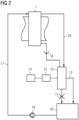
- Fig. 2 shows a block diagram of a device for determining a lubrication condition of the main bearing 7 of the wind turbine 1 according to an embodiment.
- the device for determining a lubrication condition of the main bearing 7 of the wind turbine 1 comprises a container 10 which is configured to collect a leakage lubrication oil from the main bearing 7.
- the leakage lubrication oil can be supplied to the container 10 via an inlet pipe 20.
- a funnel 18 is provided which collects the leakage lubrication oil and supplies the same to the container 10.
- the leakage oil is collected by means of gravitation so that no pressurizing or feeding means is necessary.
- the device for determining a lubrication condition further comprises an outlet 11, such as a small hole/orifice, at the bottom of the container 10, wherein the outlet 11 is configured to discharge the collected oil from the container 10 with a predetermined flow rate.
- the predetermined flow rate of the outlet 11 is adjustable or controllable. If the outlet 11 is closed, the predetermined flow rate is zero.
- the device for determining a lubrication condition further comprises an overflow passage 12 which is configured to discharge on overflow of the collected oil from the container 1.
- the overflow passage 12 is connected to the container 10 at a location which is higher than a location of the outlet 11.
- the device for determining a lubrication condition further comprises a detecting device 15 which is configured to detect an overflow of the collected oil from the container 10 through the overflow passage 12.
- the device for determining a lubrication condition further comprises a determining device 14 which is configured to determine that the lubrication condition of a main bearing 7 is sufficient if the detecting device 15 detects the overflow of the collected oil through the overflow passage 12. For example, the determining device 14 receives a signal from the detecting device 15 which indicates that there is an oil flow in the overflow passage 12. The determining device 14, which can comprise a processor and the like, then determines that the lubrication condition of the main bearing 7 is sufficient.
- the detecting device 15 can comprise a level detecting device which is configured to detect a predetermined oil level in the container 10.
- the predetermined oil level is arranged substantially at the same level where the overflow passage 12 is connected to the container 10. If the level detecting device 15 detects the predetermined oil level in the container 10, the overflow of the collected oil through the overflow passage 12 occurs and is detected thereby.
- the container 10 When the overflow from the main bearing 7 is higher than the limited amount drained from the bottom outlet 11 of the container 10, the container 10 will be filled up and the detecting device 15 in the shape of the level detecting device located at the predetermined level in the container 10 will detect that there is oil at this predetermined level in the container 10. In short, it can be said that as long as the level detecting device detects that there is the predetermined oil level in the container 10, then the amount of overflow of excess oil from the main bearing 7 is higher than the limited amount that is drained out of the outlet 11 of the container 10.
- the present invention uses a kind of difference measurement, i.e., if a total leakage lubrication oil flow amount is higher than the flow amount through the outlet 11, the excessive leakage lubrication oil escapes through the overflow passage 12. Such flow amount is then detected by the detecting device 15 which eventually results in the determination by the determining device 14 that the lubrication condition of the main bearing 7 is sufficient.
- the device for determining a lubrication condition further comprises an oil tank 16 which is configured to receive the discharged oil from the outlet 11 and the discharged oil from the overflow passage 12, and a feedback passage 17 which is configured to feed back the oil from the oil tank 16 to the main bearing 7 so that an oil circulation passage is realized.
- the feedback passage 17 preferably comprises a pump 19.
Landscapes
- Engineering & Computer Science (AREA)
- General Engineering & Computer Science (AREA)
- Mechanical Engineering (AREA)
- Chemical & Material Sciences (AREA)
- Life Sciences & Earth Sciences (AREA)
- Sustainable Development (AREA)
- Sustainable Energy (AREA)
- Combustion & Propulsion (AREA)
- Oil, Petroleum & Natural Gas (AREA)
- Wind Motors (AREA)
Abstract
Description
- The present invention relates to a device and a method of determining a lubrication condition of a main bearing of a wind turbine.
- A conventional wind turbine comprises a rotor with rotor blades. The rotor is mounted rotatable to a nacelle of the wind turbine by means of a main bearing. The rotor is thus rotatable about a rotation axis. Some oil is usually leaking from the main bearing. There may be very long periods without wind flow, where the main bearing can be completely dried, but the wind turbine must still be functional even after months or years after a leakage begins to appear.
- The main bearing is usually a single fluid film bearing (SFFB) which comprises a cavity which needs completely to be filled by the lubrication oil. To compensate for thermal expansion and contraction of the oil and for possible leakage from shaft seals, a small oil flow is continuously pumped from an oil tank into the main bearing. Thereby, there will be excess oil in the main bearing. It is difficult to monitor the presence of such oil flow, as there is only small oil pressure by gravity. Conventional oil flow meters take a greater oil pressure than what is available here. Oil levels are usually measured with level gauges, however, since the lubrication oil in the main bearing is not a level but simply fills the cavity, a conventional level gauge can hardly be used in a top part of the main bearing.
- It is the object of the present invention to provide a device and a method of determining a lubrication condition of a main bearing of a wind turbine. This object is achieved by the subject matters according to the independent claims. The present invention is further developed as set forth in the dependent claims.
- According to a first aspect of the invention, a device for determining a lubrication condition of a main bearing of a wind turbine is provided. The device comprises a container which is configured to collect a leakage lubrication oil from the main bearing; an outlet which is configured to discharge the collected oil from the container with a predetermined flow rate; an overflow passage which is configured to discharge on overflow of the collected oil from the container; a detecting device which is configured to detect an overflow of the collected oil through the overflow passage; and a determining device which is configured to determine that the lubrication condition of a main bearing is sufficient if the detecting device detects the overflow of the collected oil through the overflow passage.
- In the context of the present patent application, the "sufficient lubrication condition of a main bearing" may refer to a condition where the cavity of the main bearing is substantially completely filled by the lubrication oil.
- The present invention uses a kind of difference measurement, i.e., if a total leakage lubrication oil flow amount is higher than the flow amount through the outlet, the excessive leakage lubrication oil escapes through the overflow passage. Such flow amount is then detected by the detecting device which eventually results in the determination that the lubrication condition of a main bearing is sufficient.
- According to an embodiment, the overflow passage is connected to the container at a location which is higher than a location of the outlet. It is ensured that the flow through the overflow passage starts after a flow through the outlet.
- According to an embodiment, the detecting device comprises a level detecting device which is configured to detect a predetermined oil level in the container. Preferably, the predetermined oil level is arranged substantially at the same level where the overflow passage is connected to the container. If the level detecting device detects the predetermined oil level in the container, the overflow of the collected oil through the overflow passage is detected.
- According to an embodiment, the predetermined flow rate of the outlet is adjustable or controllable. If the outlet is fully closed, the oil flow therethrough can be even zero.
- According to an embodiment, the device for determining a lubrication condition further comprises an oil tank which is configured to receive the discharged oil from the outlet and the discharged oil from the overflow passage. According to an embodiment, the device for determining a lubrication condition further comprises a feedback passage which is configured to feed back the oil from the oil tank to the main bearing.
- According to an embodiment, the device for determining a lubrication condition further comprises at least one funnel which is configured to collect the leakage lubrication oil from the main bearing and to lead the leakage oil to the container. According to an embodiment, the leakage oil is collected by means of gravitation.
- According to a second aspect of the invention, a method of determining a lubrication condition of a main bearing of a wind turbine is provided. The method comprises the following steps: collecting a leakage lubrication oil from the main bearing in a container; discharging the collected oil from the container through an outlet with a predetermined flow rate; discharging on overflow of the collected oil from the container through an overflow passage; a detecting an overflow of the collected oil through the overflow passage; and determining that the lubrication condition of a main bearing is sufficient if the overflow of the collected oil through the overflow passage is detected.
- According to an embodiment, the method further comprises adjusting or controlling the predetermined flow rate of the outlet.
- According to an embodiment, the leakage lubrication oil is collected by means of gravitation.
- The present invention monitors that there is a leakage oil flow in overflow passage, which indicates that the lubrication condition is sufficient. The leakage oil flows by gravity alone, and the overflow is led to the container with the outlet at the bottom which allows a limited oil flow. Close to the top of the container, there is the overflow passage where oil will flow out if more oil flows into to the container than out of the container through the outlet. The detecting device detects the oil flow in the overflow passage. If there is a flow in the overflow passage, then it is determined there is a sufficient lubrication condition of the bearing because it can be ascertained that the cavity in the main bearing is sufficiently filled by the lubrication oil.
- Instead of a conventional level measurement, the present invention uses an overflow detection which can be monitored in a simple and reliable manner with only one sensor. A sophisticated sensor in the cavity of the main bearing is not required. Since the oil flows by gravity alone, no additional pressure source is necessary.
- It has to be noted that embodiments of the invention have been described with reference to different subject matters.
- In particular, some embodiments have been described with reference to apparatus type claims whereas other embodiments have been described with reference to method type claims. However, a person skilled in the art will gather from the above and the following description that, unless other notified, in addition to any combination of features belonging to one type of subject matter also any combination between features relating to different subject matters, in particular between features of the apparatus type claims and features of the method type claims is considered as to be disclosed with this application.
- The aspects defined above and further aspects of the present invention are apparent from the examples of embodiment to be described hereinafter and are explained with reference to the examples of embodiment. The invention will be described in more detail hereinafter with reference to examples of embodiment but to which the invention is not limited.
- Fig. 1
- shows a wind turbine and the different elements thereof; and
- Fig. 2
- shows a block diagram of a device for determining a lubrication condition of a main bearing of a wind turbine according to an embodiment.
- The illustrations in the drawings are schematically. It is noted that in different figures, similar or identical elements are provided with the same reference signs.
-
Fig. 1 shows a wind turbine 1. The wind turbine 1 comprises anacelle 3 and atower 2. Thenacelle 3 is mounted at the top of thetower 2. Thenacelle 3 is mounted rotatable with regard to thetower 2 by means of a yaw bearing. The axis of rotation of thenacelle 3 with regard to thetower 2 is referred to as the yaw axis. - The wind turbine 1 also comprises a hub 4 with three rotor blades 6 (of which two
rotor blades 6 are depicted inFig. 1 ). The hub 4 is mounted rotatable with regard to thenacelle 3 by means of a main bearing 7. The hub 4 is mounted rotatable about a rotor axis of rotation 8. - The wind turbine 1 furthermore comprises a
generator 5. Thegenerator 5 in turn comprises a rotor connecting thegenerator 5 with the hub 4. If the hub 4 is connected directly to thegenerator 5, the wind turbine 1 is referred to as a gearless, direct-driven wind turbine. Such agenerator 5 is referred asdirect drive generator 5. As an alternative, the hub 4 may also be connected to thegenerator 5 via a gear box. This type of wind turbine 1 is referred to as a geared wind turbine. The present invention is suitable for both types of wind turbines 1. - The
generator 5 is accommodated within thenacelle 3. Thegenerator 5 is arranged and prepared for converting the rotational energy from the hub 4 into electrical energy in the shape of an AC power. -
Fig. 2 shows a block diagram of a device for determining a lubrication condition of themain bearing 7 of the wind turbine 1 according to an embodiment. The device for determining a lubrication condition of themain bearing 7 of the wind turbine 1 comprises acontainer 10 which is configured to collect a leakage lubrication oil from themain bearing 7. The leakage lubrication oil can be supplied to thecontainer 10 via aninlet pipe 20. Preferably, afunnel 18 is provided which collects the leakage lubrication oil and supplies the same to thecontainer 10. Preferably, the leakage oil is collected by means of gravitation so that no pressurizing or feeding means is necessary. - The device for determining a lubrication condition further comprises an outlet 11, such as a small hole/orifice, at the bottom of the
container 10, wherein the outlet 11 is configured to discharge the collected oil from thecontainer 10 with a predetermined flow rate. Preferably, the predetermined flow rate of the outlet 11 is adjustable or controllable. If the outlet 11 is closed, the predetermined flow rate is zero. - The device for determining a lubrication condition further comprises an
overflow passage 12 which is configured to discharge on overflow of the collected oil from the container 1. Preferably, theoverflow passage 12 is connected to thecontainer 10 at a location which is higher than a location of the outlet 11. The device for determining a lubrication condition further comprises a detectingdevice 15 which is configured to detect an overflow of the collected oil from thecontainer 10 through theoverflow passage 12. - The device for determining a lubrication condition further comprises a determining device 14 which is configured to determine that the lubrication condition of a
main bearing 7 is sufficient if the detectingdevice 15 detects the overflow of the collected oil through theoverflow passage 12. For example, the determining device 14 receives a signal from the detectingdevice 15 which indicates that there is an oil flow in theoverflow passage 12. The determining device 14, which can comprise a processor and the like, then determines that the lubrication condition of themain bearing 7 is sufficient. - The detecting
device 15 can comprise a level detecting device which is configured to detect a predetermined oil level in thecontainer 10. The predetermined oil level is arranged substantially at the same level where theoverflow passage 12 is connected to thecontainer 10. If thelevel detecting device 15 detects the predetermined oil level in thecontainer 10, the overflow of the collected oil through theoverflow passage 12 occurs and is detected thereby. - When the overflow from the
main bearing 7 is higher than the limited amount drained from the bottom outlet 11 of thecontainer 10, thecontainer 10 will be filled up and the detectingdevice 15 in the shape of the level detecting device located at the predetermined level in thecontainer 10 will detect that there is oil at this predetermined level in thecontainer 10. In short, it can be said that as long as the level detecting device detects that there is the predetermined oil level in thecontainer 10, then the amount of overflow of excess oil from themain bearing 7 is higher than the limited amount that is drained out of the outlet 11 of thecontainer 10. - The present invention uses a kind of difference measurement, i.e., if a total leakage lubrication oil flow amount is higher than the flow amount through the outlet 11, the excessive leakage lubrication oil escapes through the
overflow passage 12. Such flow amount is then detected by the detectingdevice 15 which eventually results in the determination by the determining device 14 that the lubrication condition of themain bearing 7 is sufficient. - The device for determining a lubrication condition further comprises an
oil tank 16 which is configured to receive the discharged oil from the outlet 11 and the discharged oil from theoverflow passage 12, and afeedback passage 17 which is configured to feed back the oil from theoil tank 16 to themain bearing 7 so that an oil circulation passage is realized. Thefeedback passage 17 preferably comprises apump 19. - It should be noted that the term "comprising" does not exclude other elements or steps and "a" or "an" does not exclude a plurality. Also elements described in association with different embodiments may be combined. It should also be noted that reference signs in the claims should not be construed as limiting the scope of the claims.
-
- 1
- wind turbine
- 2
- tower
- 3
- nacelle
- 4
- hub
- 5
- generator
- 6
- blade
- 7
- main bearing
- 8
- rotational axis
- 10
- container
- 11
- outlet
- 12
- overflow passage
- 14
- determining device
- 15
- detecting device
- 16
- oil tank
- 17
- feedback passage
- 18
- funnel
- 19
- pump
- 20
- pipe
Claims (11)
- A device for determining a lubrication condition of a main bearing (7) of a wind turbine (1), the device comprising:a container (10) which is configured to collect a leakage lubrication oil from the main bearing (7);an outlet (11) which is configured to discharge the collected oil from the container (10) with a predetermined flow rate;an overflow passage (12) which is configured to discharge on overflow of the collected oil from the container (10) ;a detecting device (15) which is configured to detect an overflow of the collected oil through the overflow passage (12); anda determining device (14) which is configured to determine that the lubrication condition of a main bearing (7) is sufficient if the detecting device (15) detects the overflow of the collected oil through the overflow passage (12).
- The device for determining a lubrication condition according to the preceding claim, wherein
the overflow passage (12) is connected to the container (10) at a location which is higher than a location of the outlet (11). - The device for determining a lubrication condition according to any one of the preceding claims, wherein
the detecting device (15) comprises a level detecting device which is configured to detect a predetermined oil level in the container (10). - The device for determining a lubrication condition according to any one of the preceding claims, wherein
the predetermined flow rate of the outlet (11) is adjustable or controllable. - The device for determining a lubrication condition according to any one of the preceding claims, further comprising:
an oil tank (16) which is configured to receive the discharged oil from the outlet (11) and the discharged oil from the overflow passage (12). - The device for determining a lubrication condition according to the preceding claim, further comprising:
a feedback passage (17) which is configured to feed back the oil from the oil tank (16) to the main bearing (7). - The device for determining a lubrication condition according to any one of the preceding claims, further comprising:
at least one funnel (18) which is configured to collect the leakage lubrication oil from the main bearing (7) and to lead the leakage oil to the container (10). - The device for determining a lubrication condition according to any one of the preceding claims, wherein
the leakage oil is collected by means of gravitation. - A method of determining a lubrication condition of a main bearing (7) of a wind turbine (1), the method comprising the following steps:collecting a leakage lubrication oil from the main bearing (7) in a container (10);discharging the collected oil from the container (10) through an outlet (11) with a predetermined flow rate;discharging on overflow of the collected oil from the container (10) through an overflow passage (12);detecting an overflow of the collected oil through the overflow passage (12); anddetermining that the lubrication condition of a main bearing (7) is sufficient if the overflow of the collected oil through the overflow passage (12) is detected.
- The method according to the preceding claim, further comprising:
adjusting or controlling the predetermined flow rate of the outlet (11). - The method according to any one of claims 9 and 10, wherein
the leakage lubrication oil is collected by means of gravitation.
Priority Applications (1)
| Application Number | Priority Date | Filing Date | Title |
|---|---|---|---|
| EP21216367.9A EP4202282B1 (en) | 2021-12-21 | 2021-12-21 | Method and device for determining a lubrication condition of a main bearing of a wind turbine |
Applications Claiming Priority (1)
| Application Number | Priority Date | Filing Date | Title |
|---|---|---|---|
| EP21216367.9A EP4202282B1 (en) | 2021-12-21 | 2021-12-21 | Method and device for determining a lubrication condition of a main bearing of a wind turbine |
Publications (3)
| Publication Number | Publication Date |
|---|---|
| EP4202282A1 true EP4202282A1 (en) | 2023-06-28 |
| EP4202282C0 EP4202282C0 (en) | 2025-06-04 |
| EP4202282B1 EP4202282B1 (en) | 2025-06-04 |
Family
ID=78957580
Family Applications (1)
| Application Number | Title | Priority Date | Filing Date |
|---|---|---|---|
| EP21216367.9A Active EP4202282B1 (en) | 2021-12-21 | 2021-12-21 | Method and device for determining a lubrication condition of a main bearing of a wind turbine |
Country Status (1)
| Country | Link |
|---|---|
| EP (1) | EP4202282B1 (en) |
Citations (3)
| Publication number | Priority date | Publication date | Assignee | Title |
|---|---|---|---|---|
| DE2914630A1 (en) * | 1979-03-14 | 1980-09-25 | Bbc Brown Boveri & Cie | Monitoring unpressurised fluid flow in unfilled return tube - using container with inner overflow tube and level indicator |
| DE102005032480A1 (en) * | 2005-07-12 | 2007-02-08 | Hein, Lehmann Trenn- und Fördertechnik GmbH | Movable part e.g. bearing, oil lubrication monitoring device for use with e.g. sieving machine, has overflow pipe attached to upper end area of upstream pipe, and capacitive sensor arranged in upper end area for detecting presence of oil |
| US20110204633A1 (en) * | 2010-02-19 | 2011-08-25 | Mitsubishi Heavy Industries, Ltd. | Starting method for rotating machine and starting method for wind turbine generator |
Family Cites Families (1)
| Publication number | Priority date | Publication date | Assignee | Title |
|---|---|---|---|---|
| EP3739208B1 (en) * | 2019-05-16 | 2022-11-16 | Siemens Gamesa Renewable Energy A/S | Bearing arrangement for a wind turbine and wind turbine |
-
2021
- 2021-12-21 EP EP21216367.9A patent/EP4202282B1/en active Active
Patent Citations (3)
| Publication number | Priority date | Publication date | Assignee | Title |
|---|---|---|---|---|
| DE2914630A1 (en) * | 1979-03-14 | 1980-09-25 | Bbc Brown Boveri & Cie | Monitoring unpressurised fluid flow in unfilled return tube - using container with inner overflow tube and level indicator |
| DE102005032480A1 (en) * | 2005-07-12 | 2007-02-08 | Hein, Lehmann Trenn- und Fördertechnik GmbH | Movable part e.g. bearing, oil lubrication monitoring device for use with e.g. sieving machine, has overflow pipe attached to upper end area of upstream pipe, and capacitive sensor arranged in upper end area for detecting presence of oil |
| US20110204633A1 (en) * | 2010-02-19 | 2011-08-25 | Mitsubishi Heavy Industries, Ltd. | Starting method for rotating machine and starting method for wind turbine generator |
Also Published As
| Publication number | Publication date |
|---|---|
| EP4202282C0 (en) | 2025-06-04 |
| EP4202282B1 (en) | 2025-06-04 |
Similar Documents
| Publication | Publication Date | Title |
|---|---|---|
| US8434360B2 (en) | System and method for detecting ice on a wind turbine rotor blade | |
| EP1963670B1 (en) | Monitoring fluid levels in wind turbine component systems. | |
| EP3020961B1 (en) | Method of operating a wind turbine generator | |
| US7023105B2 (en) | Atmospheric density-dependent power adjustment for wind turbines | |
| CA1267692A (en) | Vane angle adjustment method of controlling operation of hydro turbine | |
| DK2396541T3 (en) | Wind energy systems with monitoring sensors. | |
| EP3040553A1 (en) | Wind power generation station and gearbox | |
| EP2402596B1 (en) | Wind turbine blade pitch system | |
| CN102918285A (en) | A rotor shaft bearing lubrication system | |
| WO2010093597A2 (en) | Turbine-intake tower for wind energy conversion systems | |
| CN108362497A (en) | A kind of method and system judged extremely for water turbine set bearing temperature | |
| US11879439B2 (en) | Wind turbine drivetrain component with low friction radial shaft seal | |
| CN105465003A (en) | Axial force testing system and method for vertical shielding pump | |
| CN110259702A (en) | A kind of centrifugal pump operational effect determination method | |
| EP4202282B1 (en) | Method and device for determining a lubrication condition of a main bearing of a wind turbine | |
| CN205260355U (en) | Axial force test system of vertical canned motor pump | |
| US9482207B2 (en) | Wind turbine and a method of operating a wind turbine | |
| GB2314412A (en) | Method of monitoring pump performance | |
| WO2022106149A1 (en) | A method of greasing a decanter centrifuge | |
| EP2402604B1 (en) | Wind turbine blade pitch system | |
| EP4202395A1 (en) | Method and device for determining a leakage oil amount of a main bearing of a wind turbine | |
| CN118465298A (en) | Wind direction sensor protection device and wind power generation environment intelligent monitoring method | |
| KR101195082B1 (en) | Powerplant system | |
| CN109779813A (en) | Floating-bush method for diagnosing faults under a kind of axial-flow rotary propeller type turbine-generator units | |
| EP2848801B1 (en) | Enhanced hydroelectric plant of the submerged-turbine type and corresponding control method of said plant |
Legal Events
| Date | Code | Title | Description |
|---|---|---|---|
| PUAI | Public reference made under article 153(3) epc to a published international application that has entered the european phase |
Free format text: ORIGINAL CODE: 0009012 |
|
| STAA | Information on the status of an ep patent application or granted ep patent |
Free format text: STATUS: THE APPLICATION HAS BEEN PUBLISHED |
|
| AK | Designated contracting states |
Kind code of ref document: A1 Designated state(s): AL AT BE BG CH CY CZ DE DK EE ES FI FR GB GR HR HU IE IS IT LI LT LU LV MC MK MT NL NO PL PT RO RS SE SI SK SM TR |
|
| RAP1 | Party data changed (applicant data changed or rights of an application transferred) |
Owner name: HYDAC A/S Owner name: SIEMENS GAMESA RENEWABLE ENERGY A/S |
|
| STAA | Information on the status of an ep patent application or granted ep patent |
Free format text: STATUS: REQUEST FOR EXAMINATION WAS MADE |
|
| 17P | Request for examination filed |
Effective date: 20240102 |
|
| RBV | Designated contracting states (corrected) |
Designated state(s): AL AT BE BG CH CY CZ DE DK EE ES FI FR GB GR HR HU IE IS IT LI LT LU LV MC MK MT NL NO PL PT RO RS SE SI SK SM TR |
|
| STAA | Information on the status of an ep patent application or granted ep patent |
Free format text: STATUS: EXAMINATION IS IN PROGRESS |
|
| 17Q | First examination report despatched |
Effective date: 20240807 |
|
| GRAP | Despatch of communication of intention to grant a patent |
Free format text: ORIGINAL CODE: EPIDOSNIGR1 |
|
| STAA | Information on the status of an ep patent application or granted ep patent |
Free format text: STATUS: GRANT OF PATENT IS INTENDED |
|
| INTG | Intention to grant announced |
Effective date: 20250122 |
|
| GRAS | Grant fee paid |
Free format text: ORIGINAL CODE: EPIDOSNIGR3 |
|
| GRAA | (expected) grant |
Free format text: ORIGINAL CODE: 0009210 |
|
| STAA | Information on the status of an ep patent application or granted ep patent |
Free format text: STATUS: THE PATENT HAS BEEN GRANTED |
|
| AK | Designated contracting states |
Kind code of ref document: B1 Designated state(s): AL AT BE BG CH CY CZ DE DK EE ES FI FR GB GR HR HU IE IS IT LI LT LU LV MC MK MT NL NO PL PT RO RS SE SI SK SM TR |
|
| REG | Reference to a national code |
Ref country code: GB Ref legal event code: FG4D |
|
| REG | Reference to a national code |
Ref country code: CH Ref legal event code: EP |
|
| REG | Reference to a national code |
Ref country code: DE Ref legal event code: R096 Ref document number: 602021031702 Country of ref document: DE |
|
| REG | Reference to a national code |
Ref country code: IE Ref legal event code: FG4D |
|
| U01 | Request for unitary effect filed |
Effective date: 20250623 |
|
| U07 | Unitary effect registered |
Designated state(s): AT BE BG DE DK EE FI FR IT LT LU LV MT NL PT RO SE SI Effective date: 20250701 |
|
| PG25 | Lapsed in a contracting state [announced via postgrant information from national office to epo] |
Ref country code: ES Free format text: LAPSE BECAUSE OF FAILURE TO SUBMIT A TRANSLATION OF THE DESCRIPTION OR TO PAY THE FEE WITHIN THE PRESCRIBED TIME-LIMIT Effective date: 20250604 |
|
| PG25 | Lapsed in a contracting state [announced via postgrant information from national office to epo] |
Ref country code: GR Free format text: LAPSE BECAUSE OF FAILURE TO SUBMIT A TRANSLATION OF THE DESCRIPTION OR TO PAY THE FEE WITHIN THE PRESCRIBED TIME-LIMIT Effective date: 20250905 Ref country code: NO Free format text: LAPSE BECAUSE OF FAILURE TO SUBMIT A TRANSLATION OF THE DESCRIPTION OR TO PAY THE FEE WITHIN THE PRESCRIBED TIME-LIMIT Effective date: 20250904 |
|
| PG25 | Lapsed in a contracting state [announced via postgrant information from national office to epo] |
Ref country code: PL Free format text: LAPSE BECAUSE OF FAILURE TO SUBMIT A TRANSLATION OF THE DESCRIPTION OR TO PAY THE FEE WITHIN THE PRESCRIBED TIME-LIMIT Effective date: 20250604 |
|
| PG25 | Lapsed in a contracting state [announced via postgrant information from national office to epo] |
Ref country code: HR Free format text: LAPSE BECAUSE OF FAILURE TO SUBMIT A TRANSLATION OF THE DESCRIPTION OR TO PAY THE FEE WITHIN THE PRESCRIBED TIME-LIMIT Effective date: 20250604 |
|
| PG25 | Lapsed in a contracting state [announced via postgrant information from national office to epo] |
Ref country code: RS Free format text: LAPSE BECAUSE OF FAILURE TO SUBMIT A TRANSLATION OF THE DESCRIPTION OR TO PAY THE FEE WITHIN THE PRESCRIBED TIME-LIMIT Effective date: 20250904 |
|
| PG25 | Lapsed in a contracting state [announced via postgrant information from national office to epo] |
Ref country code: IS Free format text: LAPSE BECAUSE OF FAILURE TO SUBMIT A TRANSLATION OF THE DESCRIPTION OR TO PAY THE FEE WITHIN THE PRESCRIBED TIME-LIMIT Effective date: 20251004 |
|
| PGFP | Annual fee paid to national office [announced via postgrant information from national office to epo] |
Ref country code: GB Payment date: 20251223 Year of fee payment: 5 |
|
| PG25 | Lapsed in a contracting state [announced via postgrant information from national office to epo] |
Ref country code: SM Free format text: LAPSE BECAUSE OF FAILURE TO SUBMIT A TRANSLATION OF THE DESCRIPTION OR TO PAY THE FEE WITHIN THE PRESCRIBED TIME-LIMIT Effective date: 20250604 |
|
| PG25 | Lapsed in a contracting state [announced via postgrant information from national office to epo] |
Ref country code: CZ Free format text: LAPSE BECAUSE OF FAILURE TO SUBMIT A TRANSLATION OF THE DESCRIPTION OR TO PAY THE FEE WITHIN THE PRESCRIBED TIME-LIMIT Effective date: 20250604 |
|
| PG25 | Lapsed in a contracting state [announced via postgrant information from national office to epo] |
Ref country code: SK Free format text: LAPSE BECAUSE OF FAILURE TO SUBMIT A TRANSLATION OF THE DESCRIPTION OR TO PAY THE FEE WITHIN THE PRESCRIBED TIME-LIMIT Effective date: 20250604 |
|
| U20 | Renewal fee for the european patent with unitary effect paid |
Year of fee payment: 5 Effective date: 20251223 |
|
| PLBE | No opposition filed within time limit |
Free format text: ORIGINAL CODE: 0009261 |
|
| STAA | Information on the status of an ep patent application or granted ep patent |
Free format text: STATUS: NO OPPOSITION FILED WITHIN TIME LIMIT |
|
| REG | Reference to a national code |
Ref country code: CH Ref legal event code: L10 Free format text: ST27 STATUS EVENT CODE: U-0-0-L10-L00 (AS PROVIDED BY THE NATIONAL OFFICE) Effective date: 20260416 |
|
| 26N | No opposition filed |
Effective date: 20260305 |