EP4202226A1 - Diffuser pipe alignment tool - Google Patents
Diffuser pipe alignment tool Download PDFInfo
- Publication number
- EP4202226A1 EP4202226A1 EP22215148.2A EP22215148A EP4202226A1 EP 4202226 A1 EP4202226 A1 EP 4202226A1 EP 22215148 A EP22215148 A EP 22215148A EP 4202226 A1 EP4202226 A1 EP 4202226A1
- Authority
- EP
- European Patent Office
- Prior art keywords
- alignment
- alignment tool
- diffuser
- tool
- datum
- Prior art date
- Legal status (The legal status is an assumption and is not a legal conclusion. Google has not performed a legal analysis and makes no representation as to the accuracy of the status listed.)
- Granted
Links
Images



Classifications
-
- F—MECHANICAL ENGINEERING; LIGHTING; HEATING; WEAPONS; BLASTING
- F04—POSITIVE - DISPLACEMENT MACHINES FOR LIQUIDS; PUMPS FOR LIQUIDS OR ELASTIC FLUIDS
- F04D—NON-POSITIVE-DISPLACEMENT PUMPS
- F04D29/00—Details, component parts, or accessories
- F04D29/60—Mounting; Assembling; Disassembling
- F04D29/601—Mounting; Assembling; Disassembling specially adapted for elastic fluid pumps
-
- F—MECHANICAL ENGINEERING; LIGHTING; HEATING; WEAPONS; BLASTING
- F04—POSITIVE - DISPLACEMENT MACHINES FOR LIQUIDS; PUMPS FOR LIQUIDS OR ELASTIC FLUIDS
- F04D—NON-POSITIVE-DISPLACEMENT PUMPS
- F04D17/00—Radial-flow pumps, e.g. centrifugal pumps; Helico-centrifugal pumps
- F04D17/08—Centrifugal pumps
- F04D17/10—Centrifugal pumps for compressing or evacuating
-
- F—MECHANICAL ENGINEERING; LIGHTING; HEATING; WEAPONS; BLASTING
- F01—MACHINES OR ENGINES IN GENERAL; ENGINE PLANTS IN GENERAL; STEAM ENGINES
- F01D—NON-POSITIVE DISPLACEMENT MACHINES OR ENGINES, e.g. STEAM TURBINES
- F01D25/00—Component parts, details, or accessories, not provided for in, or of interest apart from, other groups
- F01D25/28—Supporting or mounting arrangements, e.g. for turbine casing
- F01D25/285—Temporary support structures, e.g. for testing, assembling, installing, repairing; Assembly methods using such structures
-
- F—MECHANICAL ENGINEERING; LIGHTING; HEATING; WEAPONS; BLASTING
- F04—POSITIVE - DISPLACEMENT MACHINES FOR LIQUIDS; PUMPS FOR LIQUIDS OR ELASTIC FLUIDS
- F04D—NON-POSITIVE-DISPLACEMENT PUMPS
- F04D29/00—Details, component parts, or accessories
- F04D29/40—Casings; Connections of working fluid
- F04D29/42—Casings; Connections of working fluid for radial or helico-centrifugal pumps
- F04D29/44—Fluid-guiding means, e.g. diffusers
- F04D29/441—Fluid-guiding means, e.g. diffusers especially adapted for elastic fluid pumps
-
- F—MECHANICAL ENGINEERING; LIGHTING; HEATING; WEAPONS; BLASTING
- F04—POSITIVE - DISPLACEMENT MACHINES FOR LIQUIDS; PUMPS FOR LIQUIDS OR ELASTIC FLUIDS
- F04D—NON-POSITIVE-DISPLACEMENT PUMPS
- F04D29/00—Details, component parts, or accessories
- F04D29/60—Mounting; Assembling; Disassembling
- F04D29/62—Mounting; Assembling; Disassembling of radial or helico-centrifugal pumps
- F04D29/624—Mounting; Assembling; Disassembling of radial or helico-centrifugal pumps especially adapted for elastic fluid pumps
-
- F—MECHANICAL ENGINEERING; LIGHTING; HEATING; WEAPONS; BLASTING
- F05—INDEXING SCHEMES RELATING TO ENGINES OR PUMPS IN VARIOUS SUBCLASSES OF CLASSES F01-F04
- F05D—INDEXING SCHEME FOR ASPECTS RELATING TO NON-POSITIVE-DISPLACEMENT MACHINES OR ENGINES, GAS-TURBINES OR JET-PROPULSION PLANTS
- F05D2230/00—Manufacture
- F05D2230/60—Assembly methods
- F05D2230/64—Assembly methods using positioning or alignment devices for aligning or centring, e.g. pins
-
- F—MECHANICAL ENGINEERING; LIGHTING; HEATING; WEAPONS; BLASTING
- F05—INDEXING SCHEMES RELATING TO ENGINES OR PUMPS IN VARIOUS SUBCLASSES OF CLASSES F01-F04
- F05D—INDEXING SCHEME FOR ASPECTS RELATING TO NON-POSITIVE-DISPLACEMENT MACHINES OR ENGINES, GAS-TURBINES OR JET-PROPULSION PLANTS
- F05D2250/00—Geometry
- F05D2250/50—Inlet or outlet
- F05D2250/52—Outlet
Definitions
- the application relates generally to centrifugal compressors of aircraft engines and, more particularly, to diffuser pipes of such centrifugal compressors.
- Certain centrifugal compressors use diffuser pipes for diffusing high speed airflow received from an impeller of the centrifugal compressor and directing the airflow to an engine component downstream of the compressor, such as the combustor or another compression stage.
- Diffuser pipes are typically circumferentially arranged at a periphery of the impeller exit, and are designed to transform kinetic energy of the flow into pressure energy. As the diffused air exiting the diffuser pipes may impinge on the downstream combustor, any misalignment of the diffuser pipes during assembly of the engine may result in the combustor being exposed to discrete and inconsistent thermal patterns.
- an alignment tool for aligning a plurality of diffuser pipes of a centrifugal compressor relative to a casing of an aircraft engine, the alignment tool comprising: a body defining a center axis and having at least one tool datum configured for abutting against the casing; and a plurality of alignment members fixed to the body and extending radially from the body relative to the center axis, each alignment member of the plurality of alignment members having a respective fixed position relative to the at least one tool datum, the plurality of alignment members configured to abut the plurality of diffuser pipes.
- the alignment tool as defined above and described herein may further include one or more of the following features, in whole or in part, and in any combination.
- the body is annular, the plurality of alignment members circumferentially spaced apart and fixed to the body, a portion of each alignment member extending radially inwardly from the body toward the center axis of the alignment tool.
- the body is annular about the center axis, the plurality of alignment members circumferentially spaced apart and fixed to the body, each alignment member configured to be positioned circumferentially between two diffuser pipes of the plurality of diffuser pipes.
- the body includes a support being annular about the center axis, the plurality of alignment members circumferentially spaced apart and mounted to the support.
- the support is a mesh having a plurality of slots spaced circumferentially apart, the plurality of alignment members disposed in the plurality of slots.
- the plurality of alignment members are elongated cylindrical bodies.
- the at least one tool datum comprises: an axial datum defining a radially-extending surface configured to abut the casing; a radial datum defining an axially-extending surface configured to abut the casing; and a circumferential datum configured to abut the casing.
- the circumferential datum is removably mountable to the casing.
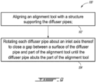
- a method of positioning exits of diffuser pipes of a centrifugal compressor in an aircraft engine comprising: aligning an alignment tool with a structure supporting the diffuser pipes; and rotating each diffuser pipe about an inlet axis thereof to close a gap between a surface of the diffuser pipe and part of the alignment tool until the diffuser pipe abuts the part of the alignment tool.
- the method as defined above and described herein may further include one or more of the following features, in whole or in part, and in any combination.
- the method further includes rotating each diffuser pipe includes rotating each diffuser pipe to abut an exit segment against the part of the alignment tool, the exits of the abutted diffuser pipes having uniform orientations.
- the method further includes rotating each diffuser pipe includes rotating each diffuser pipe one at a time.
- the method further includes fixing each diffuser pipe in position after abutting each diffuser pipe against the part of the alignment tool.
- the method further includes removing the alignment tool from the structure.
- the method further includes mounting the diffuser pipes to the support structure before aligning the alignment tool with the structure.
- the method further includes rotating each diffuser pipe includes rotating each diffuser pipe to abut the diffuser pipe against the part of the alignment tool and to provide exit segments of the diffuser pipes with uniform orientations relative to a downstream combustor.
- the method further includes mounting the diffuser pipes to the support structure before aligning the alignment tool with the structure, wherein aligning the alignment tool with the structure includes lowering the alignment tool against the support structure.
- the method further includes aligning the alignment tool with the structure includes abutting the alignment tool and the structure along at least one common datum.
- the method further includes abutting the alignment tool and the structure along at least one common datum includes abutting the alignment tool and the structure together to prevent relative movement along at least one of an axial direction, a radial direction, and a circumferential direction.
- the method further includes aligning the alignment tool with the structure includes mounting the alignment tool to the structure along at least one common datum.
- the method further includes rotating each diffuser pipe includes rotating each diffuser pipe to abut the diffuser pipe against the part of the alignment tool along a line of contact.
- an assembly of an alignment tool and of a casing having a plurality of diffuser pipes aligned along at least one datum
- the assembly comprising: a plurality of alignment members of the alignment tool, each alignment member of the plurality of alignment members having a fixed position relative to the at least one datum and having a portion extending radially toward a center axis of the alignment tool; and each diffuser pipe of the plurality of diffuser pipes extending radially from a pipe inlet to a pipe exit, each diffuser pipe abutting against the portion of each alignment member.
- the assembly defined above and described herein may further include one or more of the following features, in whole or in part, and in any combination.
- the assembly includes one or more of the following features, in any combination:
- the body is annular, the plurality of alignment members circumferentially spaced apart and fixed to the body, a portion of each alignment member extending radially inwardly from the body toward the center axis of the alignment tool.
- the body is annular about the center axis, the plurality of alignment members circumferentially spaced apart and fixed to the body, each alignment member configured to be positioned circumferentially between two diffuser pipes of the plurality of diffuser pipes.
- the body includes a support being annular about the center axis, the plurality of alignment members circumferentially spaced apart and mounted to the support.
- the support is a mesh having a plurality of slots spaced circumferentially apart, the plurality of alignment members disposed in the plurality of slots.
- the plurality of alignment members are elongated cylindrical bodies.
- the at least one tool datum comprises: an axial datum defining a radially-extending surface configured to abut the casing; a radial datum defining an axially-extending surface configured to abut the casing; and a circumferential datum configured to abut the casing.
- the circumferential datum is removably mountable to the casing.
- Fig. 1 illustrates an aircraft engine 10 of a type preferably provided for use in subsonic flight, such as a gas turbine engine, generally comprising in serial flow communication along an engine center axis 11 a fan 12 through which ambient air is propelled, a compressor section 14 for pressurizing the air, a combustor 16 in which the compressed air is mixed with fuel and ignited for generating an annular stream of hot combustion gases, and a turbine section 18 for extracting energy from the combustion gases.
- the compressor section 14 may include a plurality of stators 13 and rotors 15 (only one stator 13 and rotor 15 being shown in Fig. 1 ), and it may include a centrifugal compressor 19.
- the centrifugal compressor 19 of the compressor section 14 includes a rotatable impeller 17 with blades, and a plurality of diffuser pipes 20 which are located downstream of the impeller 17 and circumferentially disposed about a periphery of a radial outlet 17A of the impeller 17.
- the diffuser pipes 20 convert high kinetic energy at the impeller 17 exit to static pressure by slowing down fluid flow exiting the impeller.
- the diffuser pipes 20 may also redirect the air flow from a radial orientation to an axial orientation (i.e. aligned with the center axis 11).
- the diffuser pipes 20 are thus part of a compressor diffuser 20A.
- the Mach number of the flow entering the diffuser pipe 20 may be at or near sonic, while the Mach number exiting the diffuser pipe 20 may be less than 0.25 to enable stable air/fuel mixing, and light/re-light in the combustor 16.
- the impeller 17 and the diffuser pipes 20 are housed within part of an engine casing 10A.
- the engine casing 10A (sometimes referred to herein simply as the "the casing 10A") may be an integral and annular body extending along the center axis 11.
- the casing 10A is composed of interconnected casing segments 10B, sometimes referred to as "cases” or “shrouds”.
- the impeller 17 and the diffuser pipes 20 are housed within one of the casing segments 10B.
- the casing segment 10B in which the impeller 17 and the diffuser pipes 20 are housed is a gas generator casing segment 10B1.
- the impeller 17 and the diffuser pipes 20 may be housed in a different casing segment 10B.
- another casing segment 10B is the turbine support casing segment 10B2 which is mounted to the gas generator casing segment 10B1 along mated flanges.
- the turbine support casing segment 10B2 includes the combustor 16 and components of the turbine section 18, and is positioned downstream of the gas generator casing segment 10B1 so that the air exiting the diffuser pipes 20 flows toward the combustor 16.
- Fig. 2 shows the impeller 17 and the plurality of diffuser pipes 20, also referred to as "fishtail diffuser pipes", of the centrifugal compressor 19.
- Each of the diffuser pipes 20 includes a diverging (in a downstream direction) tubular body 22, formed, in one embodiment, of sheet metal.
- the enclosed tubular body 22 defines a flow passage 29 (see Fig. 3 ) extending through the diffuser pipe 20 through which the compressed fluid flow is conveyed.
- the tubular body 22 includes a first portion 24 extending generally tangentially from the periphery and radial outlet 17A of the impeller 17.
- An open end is provided at an upstream end of the tubular body 22 and forms an inlet 23 (see Fig. 3 ) of the diffuser pipe 20.
- the first portion 24 is inclined at an angle ⁇ 1 relative to a radial axis R extending from the engine axis 11.
- the angle ⁇ 1 may be at least partially tangential, or even substantially tangentially, and may further correspond to a direction of fluid flow at the exit of the blades of the impeller 17, such as to facilitate transition of the flow from the impeller 17 to the diffuser pipes 20.
- the first portion 24 of the tubular body 22 can alternatively extend more substantially along the radial axis R.
- the tubular body 22 of the diffuser pipes 20 also includes a second portion 26, which is disposed generally axially relative to the engine axis 11 and is connected to the first portion 24 by an out-of-plane curved or bend portion 28.
- An open end at the downstream end of the second portion 26 forms a pipe outlet 25 (see Fig. 3 ) of the diffuser pipe 20.
- the first portion 24 and the second portion 26 of the diffuser pipes 20 are integrally formed together and extend substantially uninterrupted between each other, via the curved, bend portion 28.
- each of the tubular bodies 22 is an enclosed and seamless structure, such that the enclosed flow passage 29 defined by each of the tubular bodies 22 is fluidly separated from the flow passage 29 defined by the other tubular bodies 22.
- the tubular bodies 22, and thus the diffuser pipes 20, are circumferentially spaced apart from one another about the center axis 11.
- the large radial velocity component of the flow exiting the impeller 17, and therefore entering the first portion 24 of each of the diffuser pipes 20, may be removed by shaping the diffuser pipe 20 with the bend portion 28, such that the flow is redirected axially through the second portion 26 before exiting via the pipe outlet 25 to the combustor 16. It will thus be appreciated that the flow exiting the impeller 17 enters the inlet 23 and the upstream first portion 24 and flows along a generally radial first direction. At the outlet of the first portion 24, the flow enters the bend portion 28 which functions to turn the flow from a substantially radial direction to a substantially axial direction.
- the bend portion 28 may form a 90 degree bend.
- the flow enters the downstream second portion 26 and flows along a substantially axial second direction different from the generally radial first direction.
- generally radial it is understood that the flow may have axial, radial, and/or circumferential velocity components, but that the axial and circumferential velocity components are much smaller in magnitude than the radial velocity component.
- generally axial it is understood that the flow may have axial, radial, and/or circumferential velocity components, but that the radial and circumferential velocity components are much smaller in magnitude than the axial velocity component.
- the tubular body 22 of each diffuser pipe 20 has a radially inner wall 22A and a radially outer wall 22B.
- the tubular body 22 also has a first side wall 22C spaced circumferentially apart across the flow passage 29 from a second side wall 22D.
- the radially inner and outer walls 22A,22B and the first and second side walls 22C,22D meet and are connected to form the enclosed flow passage 29 extending through the tubular body 22.
- the radially inner and outer walls 22A,22B and the first and second side walls 22C,22D meet and are connected to form a peripheral edge of the tubular body 22 which circumscribes the pipe outlet 25.
- the radially inner wall 22A corresponds to the wall of the tubular body 22 that has the smallest turning radius at the bend portion 28, and the radially outer wall 22B corresponds to the wall of the tubular body 22 that has the largest turning radius at the bend portion 28.
- the tubular body 22 has an outer surface 22E forming an external exposed surface of the diffuser pipe 20, and an inner surface 22F (see Fig. 4 ) along which fluid flow F moves through the diffuser pipe 20.
- the tubular body 22 diverges in the direction of fluid flow F therethrough, in that the internal flow passage 29 defined within the tubular body 22 increases in cross-sectional area between the inlet 23 and the pipe outlet 25 of the tubular body 22.
- the increase in cross-sectional area of the flow passage 29 through each diffuser pipe 20 is gradual over the length of the diffuser pipe 20.
- the direction of fluid flow F is along a pipe center axis 21 of the tubular body 22.
- the pipe center axis 21 extends through each of the first, second, and bend portions 24,26,28 and has the same orientation as these portions.
- the pipe center axis 21 is thus curved.
- the pipe center axis 21 is equidistantly spaced from the radially inner and outer walls 22A,22B of the tubular body 22, and from the first and second side walls 22C,22D, through the tubular body 22.
- the tubular body 22 has a length L defined from the inlet 23 to the pipe outlet 25.
- the length L of the tubular body 22 may be measured based on any desired feature of the diffuser pipe 20.
- the length L is the length of the pipe center axis 21 from the inlet 23 to the pipe outlet 25.
- the length L is measured along one of the walls 22A,22B,22C,22D of the tubular body 22, from the inlet 23 to the pipe outlet 25. Reference may be made herein to positions on the tubular body 22 along its length L.
- a position on the tubular body 22 that is along a last 10% of the length L is anywhere in the segment of the tubular body 22 that is upstream of the pipe outlet 25 a distance equal to 10% of the length L. This same segment is also downstream of the inlet 23 a distance equal to 90% of the length L.
- a position on the tubular body 22 that is along a first 90% of the length L is anywhere in the segment of the tubular body 22 that is downstream of the inlet 23 a distance equal to 90% of the length L. This same segment is also upstream of the pipe outlet 25 a distance equal to 10% of the length L.
- the tubular body 22 is composed of many cross-sectional profiles which are arranged or stacked one against another along the length L of the tubular body 22.
- Each cross-sectional profile is a planar contour that lies in its own plane that is transverse or normal to the pipe center axis 21.
- the orientation of the cross-sectional profiles in the frame of reference of the diffuser pipe 20 may vary over the length L of the tubular body 22, depending on where the cross-sectional profiles are located along the pipe center axis 21.
- Each cross-sectional profile defines the shape, contour, or outline of the tubular body 22 at a specific location along the pipe center axis 21. Referring to Fig.
- each diffuser pipe 20 extends radially outwardly from the inlet 23.
- the outlet 25 is spaced radially outwardly from the inlet 23, relative to the center axis 11.
- the diffuser pipe 20 defines and contains therein a throat 27 located at a point between the inlet 23 and the pipe outlet 25 of the diffuser pipe 20. More particularly, the throat 27 is located in the first portion 24 of the diffuser pipe 20, downstream of the inlet 23 and upstream of the curved portion or bend 28.
- the precise location of the throat 27 within the first portion 24 can be determined using the measured flow characteristics of the fluid flow F within the diffuser pipe 20, or can correspond to the part of the diffuser pipe 20 having the smallest cross-sectional area. In the former case, the throat 27 is referred to as the "aerodynamic throat", and in the latter case, the throat 27 is referred to as the "geometric throat".
- each diffuser pipe 20 expands in cross-sectional area along its length from the relatively small cross-sectional area of the geometric throat 27, thereby helping to diffuse the main gas flow as it is conveyed through the diffuser pipe 20.
- the location of the aerodynamic throat 27 of the diffuser pipe 20 within the first portion 24 can vary depending on numerous factors such as the flow conditions of the fluid flow F in the diffuser pipe 20, the geometry of the diffuser pipe 20, and the flow conditions upstream and/or downstream of the diffuser pipe 20.
- the location of the aerodynamic throat 27 within the first portion 24 can be suitably approximated for a given range of operating conditions of the compressor section 14 using fluid dynamic analysis, and is approximately the same as the location of the geometric throat 27 within the first portion 24.
- the diffuser pipe has a flange 27A.
- the flange 27A is a bracket or mounting extending outwardly from the tubular body 22 in a radial direction from the pipe center axis 21.
- the flange 27A is used to fixedly mount the tubular body 22 to another structure, such as a corresponding casing flange 31A of the gas generator casing segment 10B1.
- each diffuser pipe 20 is mounted to the gas generator casing segment 10B1 as follows.
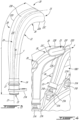
- the first portion 24 of the tubular body 22 of each diffuser pipe 20 has an end defining the inlet 23, where the end is inserted into a corresponding socket or opening in the gas generator casing segment 10B1 until the flange 27A of the diffuser pipe 20 abuts the casing flange 31A.
- the tubular body 22 may be rotated about a mounting axis that is collinear with the pipe center axis 21 at the inlet 23. This rotation of the tubular body 22 about the mounting axis helps to align a hole in the flange 27A with a hole in the casing flange 31A.
- a fastener 31B such as a bolt with a nut, may be inserted through the aligned holes in the flange 27A and the casing flange 31A, and then tightened or torqued to fixedly mount the diffuser pipe 20 to the casing flange 31A.
- the diffuser pipe 20 is mounted to the gas generator casing segment 10B1 and does not move relative to the gas generator casing segment 10B1.
- the flange 27A is located in close proximity to the inlet 23 of the diffuser pipe 20.
- the flange 27A is along the first portion 24 of the tubular body 22, and is positioned adjacent to the inlet 23 and downstream therefrom.
- the process of mounting and securing the diffuser pipes 20 to the gas generator casing segment 10B1 may affect how the second, axial portion 26 of the diffuser pipe 20, and the outlet 25 defined by the second portion 26, are oriented. More particularly, the process of mounting and securing the diffuser pipes 20 to the gas generator casing segment 10B1 may affect the orientation of the outlet 25 with respect to other components of the engine 10 which are downstream from the diffuser pipes 20, such as the combustor 16. The fluid flow F exiting the diffuser pipes 20 at the outlet 25 may impinge on the outer surface of the combustor 16.
- Variations resulting from the assembly of the diffuser pipes 20 with the gas generator casing segment 10B1, and/or during manufacturing of the diffuser pipes 20, may result in the outlets 25 not being uniformly positioned with respect to the combustor 16.
- This misalignment of the outlets 25 may affect the temperature distribution through the combustor 16.
- some of the outlets 25 may be oriented such that the fluid flow F exiting these outlets 25 impinges more directly on the outer surface of the combustor 16 than the fluid flow F exiting other outlets 25, such that some portions of the outer surface of the combustor 16 experience more cooling from the impinging fluid flow F than other portions.
- This effect may cause discrete patterns in the temperature distribution across the combustor 16, which may cause effects downstream of the combustor 16.
- the diffuser pipes 20 may have a relatively large variation in the orientation of their outlets 25 based primarily on how they are tightened or secured.
- an alignment tool 40 or feature which may be used to narrow or eliminate the variability in the orientation of the outlets 25 of the diffuser pipes 20.
- the alignment tool 40 may allow for improved control over the orientation of the outlets 25 of the differ pipes 20, which may improve the temperature distribution across the combustor 16 caused by impinging fluid flow F exiting the diffuser pipes 20.
- the alignment tool 40 is a device used to facilitate the installation of the diffuser pipes 20.
- the alignment tool 40 is a temporary structure that is used to facilitate the installation of the diffuser pipes 20, and which is removed from the engine 10 once the diffuser pipes 20 have been installed and before other components are assembled.
- the alignment tool 40 is not a component of the final, assembled engine 10.
- the alignment tool 40 mimics or replicates portions of a casing segment 10B, e.g. the turbine support casing segment 10B2, to which the gas generator casing segment 10B1 with the diffuser pipes 20 will be mounted.
- the alignment tool 40 is thus used during assembly of the diffuser pipes 20 to ensure that the outlets 25 of the diffuser pipes 20 are as close as possible to their "nominal" position, i.e. their ideal position assuming that there was no variability resulting from their manufacture or assembly.
- the alignment tool 40 is assembled with the gas generator casing segment 10B1 to form an assembly 60.
- the alignment tool 40 and the gas generator casing segment 10B1 (sometimes referred to herein simply as the "GGC 10B1") are aligned with one another, which allows the diffuser pipes 20 to be secured in their nominal position, as explained in greater detail below.
- the alignment tool 40 and the GGC 10B1 are aligned along one or more common datum(s) 62 of the assembly 60.
- the datum(s) 62 are points or portions of one or both of the alignment tool 40 and the GGC 10B1 which serve as references for assembling the alignment tool 40 and the GGC 10B1 in the desired orientation, and for precisely positioning other features of the alignment tool 40 and/or the GGC 10B1 relative to the datum(s) 62.
- the alignment tool 40 and the GGC 10B1 of the assembly 60 are secured together along one or more of the datum(s) 62, as explained in more detail below.
- the alignment tool 40 and the GGC 10B1 forming the assembly 60 are not attached to one another.
- the alignment tool 40 sits on the GGC 10B1 such that mating surface(s) defining the datum(s) 62 of the assembly 60 are in frictional contact with one another.
- the weight of the alignment tool 40 is sufficient to keep the alignment tool 40 aligned relative to the GGC 10B1 as per the datum(s) 62.
- the datum(s) 62 define or form interface(s) along which the alignment tool 40 and the GGC 10B1 are assembled.
- Both the alignment tool 40 and the GGC 10B1 have datums 62. More particularly, the alignment tool 40 and the GGC 10B1 have pairs of datums 62, where each pair of datums 62 includes a tool datum 42 of the alignment tool 40 and a casing datum 52 of the GGC 10B1. The datums 62 in each pair interface with each other.
- the tool datum 42 is an axial datum 42A that defines a surface 42AS that extends radially relative to the center axis 11
- the casing datum 52 is an axial datum 52A that defines a surface 52AS that extends radially relative to the center axis 11.
- the axial datums 42A,52A and their surfaces 42AS,52AS are formed by radially-extending and mating flanges of each of the alignment tool 40 and the GGC 10B1. When the alignment tool 40 and the GGC 10B1 are assembled together, the flanges and their axial datums 42A,52A abut one another (see Fig.
- the tool datum 42 is a radial datum 42R that defines a surface 42RS that extends annularly about the center axis 11
- the casing datum 52 is a radial datum 52R that defines a surface 52RS that extends annularly about the center axis 11.
- the radial datum 42R and the surface 42RS of the alignment tool 40 are formed by an axially-extending annular flange 42RF.
- the flange 42RF extends perpendicularly relative to the flange defining the axial datum 42A of the alignment tool 40.
- the radial datum 52R and the surface 52RS of the GGC 10B1 are formed by the radially-inner surface of an annular and axially-extending wall 52RW of the GGC 10B1.
- the flange 42RF and the wall 52RW abut one another, such that the surfaces 42RS,52RS are brought into mating contact.
- This engagement between the pair of radial datums 42R,52R prevents relative movement between the alignment tool 40 and the GGC 10B1 in a direction that is radial to the center axis 11, thereby ensuring that the alignment tool 40 and the GGC 10B1 are "radially" aligned because their radial position is controlled.
- the surfaces 42RS,52RS may be in tight-fit or low tolerance mating contact, such that the frictional engagement between the surfaces 42RS,52RS reduces or prevents relative circumferential movement between the alignment tool 40 and the GGC 10B1 in a direction about the center axis 11.
- Each of the surfaces 42RS,52RS lies in a curved plane that is annular about the center axis 11.
- the tool datum 42 is a circumferential datum 42C
- the casing datum 52 is a circumferential datum 52C.
- the circumferential datums 42C,52C may take different forms.
- the tool circumferential datum 42C includes a knob, such as a timing knob, that has or rotates an axially-extending threaded shaft. The threaded shaft is insertable into an axially-extending threaded groove of the casing circumferential datum 52C.
- the knob may be rotated to torque the threaded shaft within the threaded groove, and thereby abut the mating flanges of the axial datums 42A,42B together, which also secures the alignment tool 40 to the GGC 10B1.
- Other configurations of the circumferential datums 42C,52C are possible. This engagement between the pair of circumferential datums 42C,52C prevents relative movement between the alignment tool 40 and the GGC 10B1 in a direction that is circumferential or tangential about the center axis 11, thereby ensuring that the alignment tool 40 and the GGC 10B1 are "circumferentially” aligned because their circumferential position is controlled.
- the circumferential datums 42C,52C may be said to control "timing", also understood to be the relative angular position between the alignment tool 40 and the GGC 10B1.
- the tool circumferential datum 42C may thus be mounted to the GGC 10B1 in order to mount the alignment tool 40 to the GGC 10B1.
- the alignment tool 40 and the GGC 10B1 are secured together along only one of the datums 62 of the assembly 60 (e.g. the circumferential datums 42C,52C), which may facilitate assembly and disassembly of the alignment tool 40 and the GGC 10B1.
- the alignment tool 40 and the GGC 10B1 are secured together along two or more of the datums 62 of the assembly 60. In an alternate embodiment, the alignment tool 40 and the GGC 10B1 abut along only one pair of datums 62, such that the axial, radial and circumferential/angular positions of the alignment tool 40 and the GGC 10B1 are controlled along only one common datum 62.
- the alignment tool 40 has a plurality of alignment members 44.
- the alignment members 44 are objects or features of the alignment tool 40 which may help to narrow or eliminate the variability in the orientation of the outlets 25 of the diffuser pipes 20.
- the alignment members 44 may allow for improved control over the orientation of the outlets 25 of the differ pipes 20, which may improve the temperature distribution across the combustor 16 caused by impinging fluid flow F exiting the diffuser pipes 20.
- Each of the alignment members 44 has a fixed position relative to the common datum(s) 62 of the assembly 60.
- Each of the alignment members 44 has a fixed position relative to the tool datum(s) 42 of the alignment tool 40.
- the alignment members 44 are positioned on the alignment tool 40 such that the position (e.g. distance, orientation, etc.) of the alignment members 44 relative to the tool datum(s) 42 is known and may be predefined. Referring to Figs. 5 to 6B , the fixed position of the alignment members 44 is achieved by mounting or securing the alignment members 44 at specific locations of the alignment tool 40. In an alternate embodiment, the alignment tool 40 has a plurality of different pre-set locations for each alignment member 44 defined by bosses, apertures or the like, such that each alignment member 44 can be fixable in a pre-set position, where each pre-set position corresponds to a location of the diffuser pipes in a given configuration of the engine 10 and/or compressor diffuser 20A.
- the alignment members 44 are thus tightly controlled relative to the primary, secondary and tertiary tool datums 42 of the alignment tool 40 which interface with the primary, secondary and tertiary casing datums 52 of the GGC 10B1.
- This indexing helps the alignment tool 40 to mimic the installation of the GGC 10B1 with adjacent components of the engine 10, such as the combustion liner and turbine support casing segment 10B2, since these components interface relative to the same casing datums 52.
- each of the alignment members 44 has a portion 44P that extends radially inwardly toward the center axis 11.
- the portion 44P extends along a direction defined by a directional vector including a component vector that is radial relative to the center axis 11.
- the portion 44P may be aligned relative to a center axis 41 of the alignment tool 40.
- the center axis 41 is collinear with the center axis 11 when the alignment tool 40 is indexed to the GGC 10B1.
- the portion 44P of the alignment member 44 is all of the alignment member 44. In an alternate embodiment, the portion 44P of the alignment member 44 is less than all of the alignment member 44.
- the alignment tool 40 and the alignment members 44 may have different configurations.
- One possible configuration of the alignment tool 40 is shown in Figs. 5 to 6B .
- the alignment tool 40 has a body 46 that forms the corpus of the alignment tool 40 and provides structure thereto.
- the body 46 is annular about the center axis 41 of the alignment tool 40.
- the body 46 includes a first ring 46R1 circumscribing an opening 460 of the body 46, and a second ring 46R2.
- the second ring 46R2 is spaced apart from the first ring 46R1 in a direction that is parallel to the center axis 41.
- the diameter of the second ring 46R2 is less than the diameter of the first ring 46R1.
- the first and second rings 46R1,46R2 are interconnected by one or more spacer(s) 46S of the body 46.
- the spacer(s) 46S are axially-extending brackets or fasteners that secure the first and second rings 46R1,46R2 together and prevent relative movement between the first and second rings 46R1,46R2.
- the body 46 has three spacers 46S that are circumferentially spaced apart from each other about the center axis 41.
- Each of the spacers 46S are blocks having a central opening and extending axially relative to the center axis 41. Other configurations for the spacers 46S are possible.
- the body 46 has a rectangular or other polygonal shape.
- the alignment members 44 are mounted to the second ring 46R2 and are circumferentially spaced apart about the center axis 41. This positioning of the alignment members 44 allows their portions 44P to extend radially inwardly from the second ring 46R2 toward the center axis 41.
- the portion 44P may have a tangential/circumferential and/or axial directional vectors, such that one or more of the portions 44P has an orientation defined by a directional vector that has non-zero radial, axial and circumferential components relative to the center axis 41.
- the magnitude of the radial component is larger than the magnitude of the axial and circumferential components, such that that portions 44P are substantially radially-protruding bodies.
- the alignment members 44 are mounted to, or supported by, a support 46P of the body 46.
- the support 46P maintains the alignment members 44 in their desired orientation relative to the center axis 41 and prevents them from moving relative to the body 46 or its features.
- the support 46P maintains the alignment members 44 in their desired orientation relative to the tool datum(s) 42 and prevents them from moving relative to the tool datum(s) 42.
- the support 46P may take any configuration to achieve this functionality.
- the support 46P is an object that is annular about the center axis 41, and the alignment members 44 are circumferentially spaced apart and mounted to/supported by the support 46P. Referring to Fig.
- the support 46P is formed by, or includes, a mesh 46PM.
- the mesh 46PM is fixedly secured to the second ring 46R2 and extends radially inwardly toward the center axis 41 from the second ring 46R2.
- the mesh 46PM includes openings and slots 46PMS into which the alignment members 44 may be inserted so that the mesh 46PM can support the alignment members 44.
- the slots 46PMS are circumferentially spaced apart from each other about the center axis 41.
- the slots 46PMS are also indexed to the tool datum(s) 42 so that they, and thus the alignment members 44 received in the slots 46PMS, have the desired orientation.
- the alignment members 44 are encased in the mesh 46PM.
- the alignment members 44 are immobilized by the mesh 46PM and do not move relative to the mesh 46PM.
- the mesh 46PM serves as a support for the alignment members 44 and has a low weight, which may facilitate manipulation of the alignment tool 40.
- the mesh 46PM may be made of a lightweight material, such as plastic.
- the alignment tool 40 is lowered toward the GGC 10B1 to form the assembly 60, such that the GGC 10B1 is below the alignment tool 40 in the assembly 60.
- the mesh 46PM supports the alignment members 44 and prevents them from falling down into the GGC 10B1.
- the support 46P for the alignment members 44 may have other configurations as well.
- the support 46P is a ring or annular body to which the alignment members 44 are fixedly mounted.
- the alignment members 44 are elongated cylindrical bodies.
- the alignment members 44 are pins 44N that are circumferentially spaced apart about the center axis 41.
- the pins 44N are hollow.
- the pins 44N are solid bodies.
- the pins 44N may be made from any suitable material, such as metal, composites or plastics.
- the alignment members 44 are tubular and extend along a longitudinal axis. The pins 44N are inserted into the slots 46PMS of the mesh 46PM so that the mesh 46PM houses the pins 44N. Referring to Fig.
- an exposed segment 44NE of each pin 44N extends out of the mesh 46PM, and a covered segment 44NC of each pin 44N is housed in one of the slots 46PMS of the mesh 46PM.
- part of the pins 44N i.e. the covered segments 44NC
- Another part of the pins 44N i.e. the expose segments 44NE
- Other shapes for the alignment members 44 are possible.
- the alignment members 44 may be cuboid, polyhedron, etc.
- the support 46P and the alignment members 44 are possible.
- the support 46P is a ring or annular body with slots into which the pins 44N are threaded or otherwise secured.
- the alignment members 44 are grooves which are circumferentially spaced apart and which extend radially into an annular support 46P, or into the second ring 46R2, or into the first ring 46R1.
- the alignment members 44 are plates or other planar bodies which extend radially inwardly from an annular support 46P, or from the second ring 46R2, or from the first ring 46R1.
- the alignment members 44 are bumps which are circumferentially spaced apart and which extend radially outwardly from an annular support 46P, or from the second ring 46R2, or from the first ring 46R1.
- the alignment members 44 may be made, secured and/or indexed to the tool datum(s) 42 by any method including a fabricated assembly, being machined from solid material, additive manufacturing with subsequent machining, etc.
- the alignment members 44 help to narrow or eliminate the variability in the orientation of the outlets 25 of the diffuser pipes 20.
- FIGs. 5 to 6B when the assembly 60 of the alignment tool 40 and GGC 10B1 is formed and it is desired to orient or align the diffuser pipes 20, some or all of each diffuser pipe 20 abuts against some or all of the portion 44P of each alignment member 44 so that the diffuser pipes 20 can achieve their desired orientation.
- the diffuser pipes 20 are able to obtain the desired and accurate final orientation.
- the diffuser pipes 20 can be secured in their desired orientation by tightening the fastener 31B while the diffuser pipes 20 remain abutted against the alignment members 44, and thus while the diffuser pipes 20 remain indexed to the common datum(s) 62 of the assembly 60.
- the diffuser pipes 20 (and/or their outlets 25/exits, as described below) may thus be aligned relative to the casing datums 52 of the GGC 10B1.
- the alignment tool 40 and its alignment members 44 thus allow for aligning each individual diffuser pipe 20 to a common engine assembly flange (e.g. the flange of the GGC 10B1 that defines the casing axial datum 52A), and thus for aligning each individual diffuser pipe 20 to the center axis 11 of the engine 10.
- the alignment tool 40 and its alignment members 44 allow for aligning the outlets 25 of the diffuser pipes 20.
- the portion of each diffuser pipe 20 which is abutted against portion 44P of a corresponding alignment member 44 is the segment of the tubular body 22 which defines the outlet 25.
- the second portion 26 of the tubular body 22, which defines the outlet 25 of each diffuser pipe 20 abuts the portion 44P of each alignment member 44.
- the diffuser pipe 20 may be manipulated to abut the segments of the tubular body 22 which define the outlet 25 against the alignment members 44.
- each diffuser pipe 20 may be controlled in this manner so that exits of the diffuser pipes 20 have an orientation as close to nominal as possible.
- the alignment tool 40 and its alignment members 44 thus allow the abutted exits of the diffuser pipes 20 to have a substantially uniform orientation.
- the orientation of each outlet 25 is defined by plane at the opening forming the outlet 25, where the plane is normal to the pipe center axis 21.
- the orientation of the planes at each of the outlets 25 may be defined within the coordinate system of the GGC 10B1 and/or of the engine 10.
- the orientation of the planes at each of the outlets 25 may be made uniform or the same in this coordinate system with the alignment tool 40, within acceptable tolerances.
- the alignment tool 40 may help to reduce or eliminate the misalignment of the outlets 25. This may cause the fluid flow F exiting the diffuser pipes 20 to more uniformly impinge upon the combustor 16, and thus may help to reduce or eliminate discrete patterns in the temperature distribution across the combustor 16.
- the alignment tool 40 was able to reduce variability in the orientation of the exit of the diffuser pipe 20 that is caused when the diffuser pipe 20 is rotatably mounted to the GGC 10B1. It has been observed that the alignment tool 40 may reduce variability in the orientation of the outlet 25 to ⁇ 0.010 in. or ⁇ 0.2°, meaning that the orientation of the outlet 25 of one diffuser pipe 20 might vary slightly from the orientation of the outlet 25 of another diffuser pipe 20 by ⁇ 0.010 in. or ⁇ 0.2°. It will thus be appreciated that statements made herein that the outlets 25 of the diffuser pipes 20 have the "same" orientation, are "aligned", and/or are "uniform", are understood to include minor variations in the orientation caused when mounting the diffuser pipes 20 to the GGC 10B1.
- the reduced variability in the orientation of the outlets 25 to ⁇ 0.010 in. or ⁇ 0.2° may be an improvement of about 93% over another technique for mounting the diffuser pipe 20 to the GGC 10B1, in which the variability in the orientation of the outlet 25 was observed to be ⁇ 0.150 in. or ⁇ 3°.
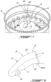
- each alignment member 44 is positioned circumferentially between two diffuser pipes 20. Each alignment member 44 is positioned circumferentially between a pair of the diffuser pipes 20. Each diffuser pipe 20 is positioned circumferentially between a pair of the alignment members 44. Each of the diffuser pipes 20 abuts only one of the alignment members 44. Referring to Fig. 7 , the number of pins 44N is equal to the number of diffuser pipes 20. Referring to Fig. 7 , the alignment tool 40 has twenty-one pins 44N, and the GGC 10B1 has twenty-one diffuser pipes 20. More or fewer pines 44N and diffuser pipes 20 are possible. In an alternate embodiment, each diffuser pipe 20 abuts against two alignment members 44.
- the segment of the diffuser pipes 20 defining the pipe outlet 25 abuts against the portion 44P of each alignment member 44 along a line of contact L.
- the line of contact L is formed at the location where the exit segment of the diffuser pipe 20 abuts the portion 44P.
- the line of contact L has a length defined as the length along which the diffuser pipe 20 abuts against the portion 44P.
- the line of contact L extends into and out of the page.
- the line of contact L may be a tangent to the curved surface of the pine 44N and/or to the outer surface of the second portion 26 of the tubular body 22.
- the line of contact L is a tangent to a point on one of the curved first and second side walls 22C,22D of the tubular body 22.
- the line of contact L has an orientation parallel to the pin 44N.
- the line of contact L is adjacent to the outlet 25.
- the line of contact L is formed on the second portion 26 of the tubular body 22.
- the alignment tool 40 thus allows for the outlets 25 of the diffuser pipes 20 to be aligned as close to nominal via the lines of contact L defined by the diffuser pipes 20 abutted to the alignment member 44. Referring to Fig.
- the line of contact L is selected to be formed at a known location on the tubular body 22 where two halves of sheet metal meet to form the tubular body 22.
- the line of contact L may be formed elsewhere on the tubular body 22, such as along an outer surface of the first or bend portions 24,28.
- the line of contact L is defined by abutting a diffuser pipe 20 against a non-cylindrical alignment member 44, such as a planar body.
- the line of contact L is a discrete point of contact formed at the location where the exit segment of the diffuser pipe 20 abuts the portion 44P.
- the line of contact L is a plane of contact formed at the location where the exit segment of the diffuser pipe 20 abuts the portion 44P.
- the alignment members 44 and/or their portions 44P may have any suitable shape which results in the line of contact L being formed with the diffuser pipe 20, such shapes including but not limited to cylindrical, cuboid, polyhedron, etc.
- the method 100 includes aligning the alignment tool 40 with a structure (e.g. the GGC 10B1) supporting the diffuser pipes 20. This may include indexing the alignment tool 40 to the structure, by manipulating the alignment tool 40 so that its orientation with respect to the structure is held fixed.
- the method 100 includes displacing one of the structure and the diffuser pipes 20 relative to the alignment tool 40 until the diffuser pipes 20 abut against parts of the alignment tool 40. This may include rotating the diffuser pies 20 about their mounting axis until their exit segments abut against the portions 44P of the alignment members 44.
- the alignment tool 40 may be aligned with the GGC 10B1 but not secured thereto, such that the GGC 10B1 is rotated relative to the alignment tool 40 about the center axis 11 in order to rotate the diffuser pipes 20 so that they abut the alignment members 44.
- the alignment tool 40 may be aligned with the GGC 10B1 but not secured thereto, such that the alignment tool 40 may be rotated relative to the GGC 10B1 about the center axis 11 in order to abut the alignment members 44 against the diffuser pipes 20.
- the casing datums 52 and the tool datums 42 are indexed along two degrees of freedom, and free to rotate relative to one another along a third circumferential degree of freedom to bring the alignment members 44 into contact with the diffuser pipes 20.
- the alignment tool 40 and the GGC 10B1 may be aligned and the diffuser pipes 20 installed as follows.
- the diffuser pipes 20 are installed on the casing flanges 31A of the GGC 10B1 one at a time.
- the first portion 24 of each diffuser pipe 20 is inserted into a corresponding socket of the casing flange 31A, and the tubular body 22 is rotated about the mounting axis (e.g. in a counter clockwise rotation direction away from casing flange 31A) until the holes of the flanges 27A,31A are aligned.
- the fastener 31B is inserted through the aligned holes and hand tightened. This process if repeated for all of the diffuser pipes 20.
- the alignment tool 40 is installed against the GGC 10B1 by aligning the datum(s) 62 and forming the assembly 60.
- the alignment tool 40 may be lowered toward the GGC 10B1 to abut the tool datum(s) 42 against the corresponding casing datum(s) 52.
- the diffuser pipes 20 are mounted to the GGC 10B1 before the assembly 60 is formed.
- the alignment tool 40 is secured to the GGC 10B1 along their circumferential datums 42C,52C.
- the diffuser pipes 20 are abutted against alignment members 44 one at a time.
- the tubular body 22 of each diffuser pipe 20 is rotated about the mounting axis (clockwise, for example) until a portion of the tubular body 22, such as the exit segment defining the outlet 25, abuts against, or makes contact with, the portion 44P of the alignment member 44.
- the alignment members 44 thus restrict or limit rotation of the diffuser pipes 20 about the mounting axis in one rotational direction, such that contact with the alignment members 44 indicates that the diffuser pipe 20 is the nominal position.
- the tubular bodies 22 may each be rotated until they form the line of contact L with the portion 44P of the alignment member 44, such that line of contact L serves to control the position of the outlets 25.
- Each tubular body 22 may be rotated until only the exposed segment 44NE of the corresponding alignment member 44 abuts against the exit segment of the diffuser pipe 20, the remaining covered segment 44NC of the alignment member 44 being housed in the mesh 46PM.
- the fastener 31B is torqued to bolt the diffuser pipe 20 to the GGC 10B1, such that the diffuser pipe 20 (and its outlet 25) is in the nominal position relative to the casing datums 52 of the GGC 10B1.
- the outlets 25 of the abutted diffuser pipes 20 have uniform orientations, helping to ensure that all of the exits of the diffuser pipes 20 are aligned (e.g. the outlets 25 replicate nominal position +/- .010").
- This process is repeated for all diffuser pipes 20, such that the process involves individually aligning the diffuser pipes 20 prior to bolting them down. Aligning the individual diffuser pipes 20 relative to casing datums 52 prior to bolting down may allow for easy separation of the assembly 60 for quick adjustments and individual diffuser pipe 20 replacement. Fifth, once all the fasteners 31B are torqued, the alignment tool 40 is removed, leaving the diffuser pipes 20 installed and aligned on the GGC 10B1.
- the embodiments described in this document provide non-limiting examples of possible implementations of the present technology.
- a person of ordinary skill in the art will recognize that changes may be made to the embodiments described herein without departing from the scope of the present technology.
- the alignment tool 40 is described herein as being used during assembly of the diffuser pipes 20, it may be used to assist with aligning other objects or components.
- the processes described herein related to the use of the alignment tool 40 may be performed during a repair or retrofit of an existing engine 10, in addition to during assembly of a new engine.
- Yet further modifications could be implemented by a person of ordinary skill in the art in view of the present disclosure, which modifications would be within the scope of the present technology.
Landscapes
- Engineering & Computer Science (AREA)
- Mechanical Engineering (AREA)
- General Engineering & Computer Science (AREA)
- Structures Of Non-Positive Displacement Pumps (AREA)
Abstract
Description
- The application relates generally to centrifugal compressors of aircraft engines and, more particularly, to diffuser pipes of such centrifugal compressors.
- Certain centrifugal compressors use diffuser pipes for diffusing high speed airflow received from an impeller of the centrifugal compressor and directing the airflow to an engine component downstream of the compressor, such as the combustor or another compression stage. Diffuser pipes are typically circumferentially arranged at a periphery of the impeller exit, and are designed to transform kinetic energy of the flow into pressure energy. As the diffused air exiting the diffuser pipes may impinge on the downstream combustor, any misalignment of the diffuser pipes during assembly of the engine may result in the combustor being exposed to discrete and inconsistent thermal patterns.
- According to an aspect of the present invention there is disclosed an alignment tool for aligning a plurality of diffuser pipes of a centrifugal compressor relative to a casing of an aircraft engine, the alignment tool comprising: a body defining a center axis and having at least one tool datum configured for abutting against the casing; and a plurality of alignment members fixed to the body and extending radially from the body relative to the center axis, each alignment member of the plurality of alignment members having a respective fixed position relative to the at least one tool datum, the plurality of alignment members configured to abut the plurality of diffuser pipes.
- The alignment tool as defined above and described herein may further include one or more of the following features, in whole or in part, and in any combination.
- Optionally, and in accordance with the above, the body is annular, the plurality of alignment members circumferentially spaced apart and fixed to the body, a portion of each alignment member extending radially inwardly from the body toward the center axis of the alignment tool.
- Optionally, and in accordance with any of the above, the body is annular about the center axis, the plurality of alignment members circumferentially spaced apart and fixed to the body, each alignment member configured to be positioned circumferentially between two diffuser pipes of the plurality of diffuser pipes.
- Optionally, and in accordance with any of the above, the body includes a support being annular about the center axis, the plurality of alignment members circumferentially spaced apart and mounted to the support.
- Optionally, and in accordance with any of the above, the support is a mesh having a plurality of slots spaced circumferentially apart, the plurality of alignment members disposed in the plurality of slots.
- Optionally, and in accordance with any of the above, the plurality of alignment members are elongated cylindrical bodies.
- Optionally, and in accordance with any of the above, the at least one tool datum comprises: an axial datum defining a radially-extending surface configured to abut the casing; a radial datum defining an axially-extending surface configured to abut the casing; and a circumferential datum configured to abut the casing.
- Optionally, and in accordance with any of the above, the circumferential datum is removably mountable to the casing.
- According to another aspect of the invention, there is disclosed a method of positioning exits of diffuser pipes of a centrifugal compressor in an aircraft engine, the method comprising: aligning an alignment tool with a structure supporting the diffuser pipes; and rotating each diffuser pipe about an inlet axis thereof to close a gap between a surface of the diffuser pipe and part of the alignment tool until the diffuser pipe abuts the part of the alignment tool.
- The method as defined above and described herein may further include one or more of the following features, in whole or in part, and in any combination.
- Optionally, and in accordance with any of the above, the method further includes rotating each diffuser pipe includes rotating each diffuser pipe to abut an exit segment against the part of the alignment tool, the exits of the abutted diffuser pipes having uniform orientations.
- Optionally, and in accordance with any of the above, the method further includes rotating each diffuser pipe includes rotating each diffuser pipe one at a time.
- Optionally, and in accordance with any of the above, the method further includes fixing each diffuser pipe in position after abutting each diffuser pipe against the part of the alignment tool.
- Optionally, and in accordance with any of the above, the method further includes removing the alignment tool from the structure.
- Optionally, and in accordance with any of the above, the method further includes mounting the diffuser pipes to the support structure before aligning the alignment tool with the structure.
- Optionally, and in accordance with any of the above, the method further includes rotating each diffuser pipe includes rotating each diffuser pipe to abut the diffuser pipe against the part of the alignment tool and to provide exit segments of the diffuser pipes with uniform orientations relative to a downstream combustor.
- Optionally, and in accordance with any of the above, the method further includes mounting the diffuser pipes to the support structure before aligning the alignment tool with the structure, wherein aligning the alignment tool with the structure includes lowering the alignment tool against the support structure.
- Optionally, and in accordance with any of the above, the method further includes aligning the alignment tool with the structure includes abutting the alignment tool and the structure along at least one common datum.
- Optionally, and in accordance with any of the above, the method further includes abutting the alignment tool and the structure along at least one common datum includes abutting the alignment tool and the structure together to prevent relative movement along at least one of an axial direction, a radial direction, and a circumferential direction.
- Optionally, and in accordance with any of the above, the method further includes aligning the alignment tool with the structure includes mounting the alignment tool to the structure along at least one common datum.
- Optionally, and in accordance with any of the above, the method further includes rotating each diffuser pipe includes rotating each diffuser pipe to abut the diffuser pipe against the part of the alignment tool along a line of contact.
- According to an aspect of the present invention, there disclosed an assembly of an alignment tool and of a casing having a plurality of diffuser pipes, the assembly aligned along at least one datum, the assembly comprising: a plurality of alignment members of the alignment tool, each alignment member of the plurality of alignment members having a fixed position relative to the at least one datum and having a portion extending radially toward a center axis of the alignment tool; and each diffuser pipe of the plurality of diffuser pipes extending radially from a pipe inlet to a pipe exit, each diffuser pipe abutting against the portion of each alignment member.
- The assembly defined above and described herein may further include one or more of the following features, in whole or in part, and in any combination.
- Optionally, and in accordance with any of the above, the assembly includes one or more of the following features, in any combination:
Optionally, and in accordance with any of the above, the body is annular, the plurality of alignment members circumferentially spaced apart and fixed to the body, a portion of each alignment member extending radially inwardly from the body toward the center axis of the alignment tool. - Optionally, and in accordance with any of the above, the body is annular about the center axis, the plurality of alignment members circumferentially spaced apart and fixed to the body, each alignment member configured to be positioned circumferentially between two diffuser pipes of the plurality of diffuser pipes.
- Optionally, and in accordance with any of the above, the body includes a support being annular about the center axis, the plurality of alignment members circumferentially spaced apart and mounted to the support.
- Optionally, and in accordance with any of the above, the support is a mesh having a plurality of slots spaced circumferentially apart, the plurality of alignment members disposed in the plurality of slots.
- Optionally, and in accordance with any of the above, the plurality of alignment members are elongated cylindrical bodies.
- Optionally, and in accordance with any of the above, the at least one tool datum comprises: an axial datum defining a radially-extending surface configured to abut the casing; a radial datum defining an axially-extending surface configured to abut the casing; and a circumferential datum configured to abut the casing.
- Optionally, and in accordance with any of the above, the circumferential datum is removably mountable to the casing.
- Reference is now made to the accompanying figures in which:
-
Fig. 1 is a schematic cross sectional view of a gas turbine engine; -
Fig. 2 is a perspective view of a centrifugal compressor of the gas turbine ofFig. 1 , the centrifugal compressor including an impeller and diffuser pipes; -
Fig. 3 is a perspective view of one of the diffuser pipes ofFig. 2 ; -
Fig. 4 is a perspective view of some of the diffuser pipes ofFig. 2 ; -
Fig. 5 is a perspective view of an alignment tool; -
Fig. 6A is a perspective view of the alignment tool ofFig. 5 assembled with a casing of the gas turbine engine ofFig. 1 ; -
Fig. 6B is a cross-sectional view of the assembled alignment tool and casing ofFig. 6A ; -
Fig. 7 is a perspective view of the assembled alignment tool and casing ofFig. 6A ; -
Fig. 8 is a view of one of the diffuser pipes ofFig. 2 ; and -
Fig. 9 is an example flow chart of a method of aligning diffuser pipes. -
Fig. 1 illustrates anaircraft engine 10 of a type preferably provided for use in subsonic flight, such as a gas turbine engine, generally comprising in serial flow communication along an engine center axis 11 afan 12 through which ambient air is propelled, acompressor section 14 for pressurizing the air, acombustor 16 in which the compressed air is mixed with fuel and ignited for generating an annular stream of hot combustion gases, and aturbine section 18 for extracting energy from the combustion gases. Thecompressor section 14 may include a plurality ofstators 13 and rotors 15 (only onestator 13 androtor 15 being shown inFig. 1 ), and it may include acentrifugal compressor 19. - The
centrifugal compressor 19 of thecompressor section 14 includes arotatable impeller 17 with blades, and a plurality ofdiffuser pipes 20 which are located downstream of theimpeller 17 and circumferentially disposed about a periphery of aradial outlet 17A of theimpeller 17. Thediffuser pipes 20 convert high kinetic energy at theimpeller 17 exit to static pressure by slowing down fluid flow exiting the impeller. Thediffuser pipes 20 may also redirect the air flow from a radial orientation to an axial orientation (i.e. aligned with the center axis 11). Thediffuser pipes 20 are thus part of acompressor diffuser 20A. In most cases, the Mach number of the flow entering thediffuser pipe 20 may be at or near sonic, while the Mach number exiting thediffuser pipe 20 may be less than 0.25 to enable stable air/fuel mixing, and light/re-light in thecombustor 16. - The
impeller 17 and thediffuser pipes 20 are housed within part of anengine casing 10A. In an embodiment, theengine casing 10A (sometimes referred to herein simply as the "thecasing 10A") may be an integral and annular body extending along thecenter axis 11. Referring toFig. 1 , thecasing 10A is composed ofinterconnected casing segments 10B, sometimes referred to as "cases" or "shrouds". Theimpeller 17 and thediffuser pipes 20 are housed within one of thecasing segments 10B. In the configuration of theengine casing 10A shown inFig. 1 , thecasing segment 10B in which theimpeller 17 and thediffuser pipes 20 are housed is a gas generator casing segment 10B1. Theimpeller 17 and thediffuser pipes 20 may be housed in adifferent casing segment 10B. In the configuration of theengine casing 10A shown inFig. 1 , anothercasing segment 10B is the turbine support casing segment 10B2 which is mounted to the gas generator casing segment 10B1 along mated flanges. The turbine support casing segment 10B2 includes thecombustor 16 and components of theturbine section 18, and is positioned downstream of the gas generator casing segment 10B1 so that the air exiting thediffuser pipes 20 flows toward thecombustor 16. -
Fig. 2 shows theimpeller 17 and the plurality ofdiffuser pipes 20, also referred to as "fishtail diffuser pipes", of thecentrifugal compressor 19. Each of thediffuser pipes 20 includes a diverging (in a downstream direction)tubular body 22, formed, in one embodiment, of sheet metal. The enclosedtubular body 22 defines a flow passage 29 (seeFig. 3 ) extending through thediffuser pipe 20 through which the compressed fluid flow is conveyed. Thetubular body 22 includes afirst portion 24 extending generally tangentially from the periphery andradial outlet 17A of theimpeller 17. An open end is provided at an upstream end of thetubular body 22 and forms an inlet 23 (seeFig. 3 ) of thediffuser pipe 20. Thefirst portion 24 is inclined at an angle θ1 relative to a radial axis R extending from theengine axis 11. The angle θ1 may be at least partially tangential, or even substantially tangentially, and may further correspond to a direction of fluid flow at the exit of the blades of theimpeller 17, such as to facilitate transition of the flow from theimpeller 17 to thediffuser pipes 20. Thefirst portion 24 of thetubular body 22 can alternatively extend more substantially along the radial axis R. - The
tubular body 22 of thediffuser pipes 20 also includes asecond portion 26, which is disposed generally axially relative to theengine axis 11 and is connected to thefirst portion 24 by an out-of-plane curved orbend portion 28. An open end at the downstream end of thesecond portion 26 forms a pipe outlet 25 (seeFig. 3 ) of thediffuser pipe 20. Preferably, but not necessarily, thefirst portion 24 and thesecond portion 26 of thediffuser pipes 20 are integrally formed together and extend substantially uninterrupted between each other, via the curved,bend portion 28. Referring toFig. 3 , each of thetubular bodies 22 is an enclosed and seamless structure, such that theenclosed flow passage 29 defined by each of thetubular bodies 22 is fluidly separated from theflow passage 29 defined by the othertubular bodies 22. Thetubular bodies 22, and thus thediffuser pipes 20, are circumferentially spaced apart from one another about thecenter axis 11. - The large radial velocity component of the flow exiting the
impeller 17, and therefore entering thefirst portion 24 of each of thediffuser pipes 20, may be removed by shaping thediffuser pipe 20 with thebend portion 28, such that the flow is redirected axially through thesecond portion 26 before exiting via thepipe outlet 25 to thecombustor 16. It will thus be appreciated that the flow exiting theimpeller 17 enters theinlet 23 and the upstreamfirst portion 24 and flows along a generally radial first direction. At the outlet of thefirst portion 24, the flow enters thebend portion 28 which functions to turn the flow from a substantially radial direction to a substantially axial direction. Thebend portion 28 may form a 90 degree bend. At the outlet of thebend portion 28, the flow enters the downstreamsecond portion 26 and flows along a substantially axial second direction different from the generally radial first direction. By "generally radial", it is understood that the flow may have axial, radial, and/or circumferential velocity components, but that the axial and circumferential velocity components are much smaller in magnitude than the radial velocity component. Similarly, by "generally axial", it is understood that the flow may have axial, radial, and/or circumferential velocity components, but that the radial and circumferential velocity components are much smaller in magnitude than the axial velocity component. - Referring to
Fig. 3 , thetubular body 22 of eachdiffuser pipe 20 has a radiallyinner wall 22A and a radiallyouter wall 22B. Thetubular body 22 also has afirst side wall 22C spaced circumferentially apart across theflow passage 29 from asecond side wall 22D. The radially inner andouter walls second side walls enclosed flow passage 29 extending through thetubular body 22. The radially inner andouter walls second side walls tubular body 22 which circumscribes thepipe outlet 25. The radiallyinner wall 22A corresponds to the wall of thetubular body 22 that has the smallest turning radius at thebend portion 28, and the radiallyouter wall 22B corresponds to the wall of thetubular body 22 that has the largest turning radius at thebend portion 28. Thetubular body 22 has anouter surface 22E forming an external exposed surface of thediffuser pipe 20, and aninner surface 22F (seeFig. 4 ) along which fluid flow F moves through thediffuser pipe 20. - The
tubular body 22 diverges in the direction of fluid flow F therethrough, in that theinternal flow passage 29 defined within thetubular body 22 increases in cross-sectional area between theinlet 23 and thepipe outlet 25 of thetubular body 22. The increase in cross-sectional area of theflow passage 29 through eachdiffuser pipe 20 is gradual over the length of thediffuser pipe 20. The direction of fluid flow F is along apipe center axis 21 of thetubular body 22. Thepipe center axis 21 extends through each of the first, second, and bendportions pipe center axis 21 is thus curved. In an embodiment, thepipe center axis 21 is equidistantly spaced from the radially inner andouter walls tubular body 22, and from the first andsecond side walls tubular body 22. - Still referring to
Fig. 3 , thetubular body 22 has a length L defined from theinlet 23 to thepipe outlet 25. The length L of thetubular body 22 may be measured based on any desired feature of thediffuser pipe 20. For example, inFig. 3 , the length L is the length of thepipe center axis 21 from theinlet 23 to thepipe outlet 25. In an alternate embodiment, the length L is measured along one of thewalls tubular body 22, from theinlet 23 to thepipe outlet 25. Reference may be made herein to positions on thetubular body 22 along its length L. For example, a position on thetubular body 22 that is along a last 10% of the length L is anywhere in the segment of thetubular body 22 that is upstream of the pipe outlet 25 a distance equal to 10% of the length L. This same segment is also downstream of the inlet 23 a distance equal to 90% of the length L. Similarly, a position on thetubular body 22 that is along a first 90% of the length L is anywhere in the segment of thetubular body 22 that is downstream of the inlet 23 a distance equal to 90% of the length L. This same segment is also upstream of the pipe outlet 25 a distance equal to 10% of the length L. - The
tubular body 22 is composed of many cross-sectional profiles which are arranged or stacked one against another along the length L of thetubular body 22. Each cross-sectional profile is a planar contour that lies in its own plane that is transverse or normal to thepipe center axis 21. The orientation of the cross-sectional profiles in the frame of reference of thediffuser pipe 20 may vary over the length L of thetubular body 22, depending on where the cross-sectional profiles are located along thepipe center axis 21. Each cross-sectional profile defines the shape, contour, or outline of thetubular body 22 at a specific location along thepipe center axis 21. Referring toFig. 3 , theoutlet 25 of each diffusepipe 20 is positioned radially outwardly of theinlet 23, relative to thecenter axis 11 of theengine 10. Thus, over its length L, eachdiffuser pipe 20 extends radially outwardly from theinlet 23. Theoutlet 25 is spaced radially outwardly from theinlet 23, relative to thecenter axis 11. - Referring to
Fig. 3 , thediffuser pipe 20 defines and contains therein athroat 27 located at a point between theinlet 23 and thepipe outlet 25 of thediffuser pipe 20. More particularly, thethroat 27 is located in thefirst portion 24 of thediffuser pipe 20, downstream of theinlet 23 and upstream of the curved portion orbend 28. The precise location of thethroat 27 within thefirst portion 24 can be determined using the measured flow characteristics of the fluid flow F within thediffuser pipe 20, or can correspond to the part of thediffuser pipe 20 having the smallest cross-sectional area. In the former case, thethroat 27 is referred to as the "aerodynamic throat", and in the latter case, thethroat 27 is referred to as the "geometric throat". It is understood, however, that the aerodynamic throat may not necessarily occur at the same point as the geometric throat. For thegeometric throat 27, sometimes referred to as the "neck" of thediffuser pipe 20, eachdiffuser pipe 20 expands in cross-sectional area along its length from the relatively small cross-sectional area of thegeometric throat 27, thereby helping to diffuse the main gas flow as it is conveyed through thediffuser pipe 20. - The location of the
aerodynamic throat 27 of thediffuser pipe 20 within thefirst portion 24 can vary depending on numerous factors such as the flow conditions of the fluid flow F in thediffuser pipe 20, the geometry of thediffuser pipe 20, and the flow conditions upstream and/or downstream of thediffuser pipe 20. For most applications, the location of theaerodynamic throat 27 within thefirst portion 24 can be suitably approximated for a given range of operating conditions of thecompressor section 14 using fluid dynamic analysis, and is approximately the same as the location of thegeometric throat 27 within thefirst portion 24. - Referring to
Figs. 3 and 4 , the diffuser pipe has aflange 27A. Theflange 27A is a bracket or mounting extending outwardly from thetubular body 22 in a radial direction from thepipe center axis 21. Theflange 27A is used to fixedly mount thetubular body 22 to another structure, such as a correspondingcasing flange 31A of the gas generator casing segment 10B1. In the configuration ofFigs. 3 and 4 , eachdiffuser pipe 20 is mounted to the gas generator casing segment 10B1 as follows. Thefirst portion 24 of thetubular body 22 of eachdiffuser pipe 20 has an end defining theinlet 23, where the end is inserted into a corresponding socket or opening in the gas generator casing segment 10B1 until theflange 27A of thediffuser pipe 20 abuts thecasing flange 31A. Thetubular body 22 may be rotated about a mounting axis that is collinear with thepipe center axis 21 at theinlet 23. This rotation of thetubular body 22 about the mounting axis helps to align a hole in theflange 27A with a hole in thecasing flange 31A. When the holes in theflanges fastener 31B, such as a bolt with a nut, may be inserted through the aligned holes in theflange 27A and thecasing flange 31A, and then tightened or torqued to fixedly mount thediffuser pipe 20 to thecasing flange 31A. Once thefastener 31B is tightened, thediffuser pipe 20 is mounted to the gas generator casing segment 10B1 and does not move relative to the gas generator casing segment 10B1. Referring toFigs. 3 and 4 , theflange 27A is located in close proximity to theinlet 23 of thediffuser pipe 20. Theflange 27A is along thefirst portion 24 of thetubular body 22, and is positioned adjacent to theinlet 23 and downstream therefrom. - The process of mounting and securing the
diffuser pipes 20 to the gas generator casing segment 10B1 may affect how the second,axial portion 26 of thediffuser pipe 20, and theoutlet 25 defined by thesecond portion 26, are oriented. More particularly, the process of mounting and securing thediffuser pipes 20 to the gas generator casing segment 10B1 may affect the orientation of theoutlet 25 with respect to other components of theengine 10 which are downstream from thediffuser pipes 20, such as thecombustor 16. The fluid flow F exiting thediffuser pipes 20 at theoutlet 25 may impinge on the outer surface of thecombustor 16. Variations resulting from the assembly of thediffuser pipes 20 with the gas generator casing segment 10B1, and/or during manufacturing of thediffuser pipes 20, may result in theoutlets 25 not being uniformly positioned with respect to thecombustor 16. This misalignment of theoutlets 25 may affect the temperature distribution through thecombustor 16. For example, some of theoutlets 25 may be oriented such that the fluid flow F exiting theseoutlets 25 impinges more directly on the outer surface of thecombustor 16 than the fluid flow F exitingother outlets 25, such that some portions of the outer surface of thecombustor 16 experience more cooling from the impinging fluid flow F than other portions. This effect may cause discrete patterns in the temperature distribution across thecombustor 16, which may cause effects downstream of thecombustor 16. Thus, thediffuser pipes 20 may have a relatively large variation in the orientation of theiroutlets 25 based primarily on how they are tightened or secured. - It may be possible to provide the
outlets 25 with a more uniform and consistent orientation across all of thediffuser pipes 20, so as to reduce or avoid the problems described above regarding the distribution of temperature across thecombustor 16. Referring toFig. 5 , there is disclosed analignment tool 40 or feature which may be used to narrow or eliminate the variability in the orientation of theoutlets 25 of thediffuser pipes 20. Thealignment tool 40 may allow for improved control over the orientation of theoutlets 25 of the differpipes 20, which may improve the temperature distribution across thecombustor 16 caused by impinging fluid flow F exiting thediffuser pipes 20. Thealignment tool 40 is a device used to facilitate the installation of thediffuser pipes 20. In an embodiment, thealignment tool 40 is a temporary structure that is used to facilitate the installation of thediffuser pipes 20, and which is removed from theengine 10 once thediffuser pipes 20 have been installed and before other components are assembled. In an embodiment, thealignment tool 40 is not a component of the final, assembledengine 10. In an embodiment, and as explained in greater detail below, thealignment tool 40 mimics or replicates portions of acasing segment 10B, e.g. the turbine support casing segment 10B2, to which the gas generator casing segment 10B1 with thediffuser pipes 20 will be mounted. Thealignment tool 40 is thus used during assembly of thediffuser pipes 20 to ensure that theoutlets 25 of thediffuser pipes 20 are as close as possible to their "nominal" position, i.e. their ideal position assuming that there was no variability resulting from their manufacture or assembly. - Referring to
Figs. 6A and 6B , thealignment tool 40 is assembled with the gas generator casing segment 10B1 to form anassembly 60. Thealignment tool 40 and the gas generator casing segment 10B1 (sometimes referred to herein simply as the "GGC 10B1") are aligned with one another, which allows thediffuser pipes 20 to be secured in their nominal position, as explained in greater detail below. Thealignment tool 40 and the GGC 10B1 are aligned along one or more common datum(s) 62 of theassembly 60. The datum(s) 62 are points or portions of one or both of thealignment tool 40 and the GGC 10B1 which serve as references for assembling thealignment tool 40 and the GGC 10B1 in the desired orientation, and for precisely positioning other features of thealignment tool 40 and/or the GGC 10B1 relative to the datum(s) 62. Referring toFigs. 6A and 6B , thealignment tool 40 and the GGC 10B1 of theassembly 60 are secured together along one or more of the datum(s) 62, as explained in more detail below. In an alternate embodiment, thealignment tool 40 and the GGC 10B1 forming theassembly 60 are not attached to one another. In one example of such an alternate embodiment, thealignment tool 40 sits on the GGC 10B1 such that mating surface(s) defining the datum(s) 62 of theassembly 60 are in frictional contact with one another. In such a configuration, the weight of thealignment tool 40 is sufficient to keep thealignment tool 40 aligned relative to the GGC 10B1 as per the datum(s) 62. In an embodiment, the datum(s) 62 define or form interface(s) along which thealignment tool 40 and the GGC 10B1 are assembled. - One possible arrangement for the datum(s) 62 of the
assembly 60 is now described with reference toFigs. 5 to 6B . Both thealignment tool 40 and the GGC 10B1 have datums 62. More particularly, thealignment tool 40 and the GGC 10B1 have pairs of datums 62, where each pair of datums 62 includes a tool datum 42 of thealignment tool 40 and a casing datum 52 of the GGC 10B1. The datums 62 in each pair interface with each other. - In one example of a pair of datums 62, the tool datum 42 is an axial datum 42A that defines a surface 42AS that extends radially relative to the
center axis 11, and the casing datum 52 is an axial datum 52A that defines a surface 52AS that extends radially relative to thecenter axis 11. The axial datums 42A,52A and their surfaces 42AS,52AS are formed by radially-extending and mating flanges of each of thealignment tool 40 and the GGC 10B1. When thealignment tool 40 and the GGC 10B1 are assembled together, the flanges and their axial datums 42A,52A abut one another (seeFig. 6B ), such that the surfaces 42AS,52AS are brought into mating contact. This engagement between the pair of axial datums 42A,52A prevents relative movement between thealignment tool 40 and the GGC 10B1 in a direction that is parallel to thecenter axis 11, thereby ensuring that thealignment tool 40 and the GGC 10B1 are "axially" aligned because their axial position is controlled. Each of the surfaces 42AS,52AS lies in a plane that is perpendicular to thecenter axis 11, and that is annular about thecenter axis 11. - In another example of a pair of datums 62, and referring to
Figs. 5 to 6B , the tool datum 42 is a radial datum 42R that defines a surface 42RS that extends annularly about thecenter axis 11, and the casing datum 52 is a radial datum 52R that defines a surface 52RS that extends annularly about thecenter axis 11. The radial datum 42R and the surface 42RS of thealignment tool 40 are formed by an axially-extending annular flange 42RF. The flange 42RF extends perpendicularly relative to the flange defining the axial datum 42A of thealignment tool 40. The radial datum 52R and the surface 52RS of the GGC 10B1 are formed by the radially-inner surface of an annular and axially-extending wall 52RW of the GGC 10B1. When thealignment tool 40 and the GGC 10B1 are assembled together, the flange 42RF and the wall 52RW abut one another, such that the surfaces 42RS,52RS are brought into mating contact. This engagement between the pair of radial datums 42R,52R prevents relative movement between thealignment tool 40 and the GGC 10B1 in a direction that is radial to thecenter axis 11, thereby ensuring that thealignment tool 40 and the GGC 10B1 are "radially" aligned because their radial position is controlled. The surfaces 42RS,52RS may be in tight-fit or low tolerance mating contact, such that the frictional engagement between the surfaces 42RS,52RS reduces or prevents relative circumferential movement between thealignment tool 40 and the GGC 10B1 in a direction about thecenter axis 11. Each of the surfaces 42RS,52RS lies in a curved plane that is annular about thecenter axis 11. - Relative circumferential movement between the
alignment tool 40 and the GGC 10B1 may be further reduced or prevented with another example of a pair of datums 62. Referring toFigs. 5 to 6B , the tool datum 42 is a circumferential datum 42C, and the casing datum 52 is a circumferential datum 52C. The circumferential datums 42C,52C may take different forms. For example, and referring toFigs. 5 to 6B , the tool circumferential datum 42C includes a knob, such as a timing knob, that has or rotates an axially-extending threaded shaft. The threaded shaft is insertable into an axially-extending threaded groove of the casing circumferential datum 52C. The knob may be rotated to torque the threaded shaft within the threaded groove, and thereby abut the mating flanges of the axial datums 42A,42B together, which also secures thealignment tool 40 to the GGC 10B1. Other configurations of the circumferential datums 42C,52C are possible. This engagement between the pair of circumferential datums 42C,52C prevents relative movement between thealignment tool 40 and the GGC 10B1 in a direction that is circumferential or tangential about thecenter axis 11, thereby ensuring that thealignment tool 40 and the GGC 10B1 are "circumferentially" aligned because their circumferential position is controlled. The circumferential datums 42C,52C may be said to control "timing", also understood to be the relative angular position between thealignment tool 40 and the GGC 10B1. The tool circumferential datum 42C may thus be mounted to the GGC 10B1 in order to mount thealignment tool 40 to the GGC 10B1. Thus, and referring toFigs. 5 to 6B , thealignment tool 40 and the GGC 10B1 are secured together along only one of the datums 62 of the assembly 60 (e.g. the circumferential datums 42C,52C), which may facilitate assembly and disassembly of thealignment tool 40 and the GGC 10B1. In an alternate embodiment, thealignment tool 40 and the GGC 10B1 are secured together along two or more of the datums 62 of theassembly 60. In an alternate embodiment, thealignment tool 40 and the GGC 10B1 abut along only one pair of datums 62, such that the axial, radial and circumferential/angular positions of thealignment tool 40 and the GGC 10B1 are controlled along only one common datum 62. - Referring to
Figs. 5 to 6B , thealignment tool 40 has a plurality ofalignment members 44. Thealignment members 44 are objects or features of thealignment tool 40 which may help to narrow or eliminate the variability in the orientation of theoutlets 25 of thediffuser pipes 20. Thealignment members 44 may allow for improved control over the orientation of theoutlets 25 of the differpipes 20, which may improve the temperature distribution across thecombustor 16 caused by impinging fluid flow F exiting thediffuser pipes 20. Each of thealignment members 44 has a fixed position relative to the common datum(s) 62 of theassembly 60. Each of thealignment members 44 has a fixed position relative to the tool datum(s) 42 of thealignment tool 40. By "fixed position", it is understood that thealignment members 44 are positioned on thealignment tool 40 such that the position (e.g. distance, orientation, etc.) of thealignment members 44 relative to the tool datum(s) 42 is known and may be predefined. Referring toFigs. 5 to 6B , the fixed position of thealignment members 44 is achieved by mounting or securing thealignment members 44 at specific locations of thealignment tool 40. In an alternate embodiment, thealignment tool 40 has a plurality of different pre-set locations for eachalignment member 44 defined by bosses, apertures or the like, such that eachalignment member 44 can be fixable in a pre-set position, where each pre-set position corresponds to a location of the diffuser pipes in a given configuration of theengine 10 and/orcompressor diffuser 20A. Thealignment members 44 are thus tightly controlled relative to the primary, secondary and tertiary tool datums 42 of thealignment tool 40 which interface with the primary, secondary and tertiary casing datums 52 of the GGC 10B1. This indexing helps thealignment tool 40 to mimic the installation of the GGC 10B1 with adjacent components of theengine 10, such as the combustion liner and turbine support casing segment 10B2, since these components interface relative to the same casing datums 52. - Referring to
Figs. 5 to 6B , each of thealignment members 44 has aportion 44P that extends radially inwardly toward thecenter axis 11. Theportion 44P extends along a direction defined by a directional vector including a component vector that is radial relative to thecenter axis 11. Theportion 44P may be aligned relative to a center axis 41 of thealignment tool 40. The center axis 41 is collinear with thecenter axis 11 when thealignment tool 40 is indexed to the GGC 10B1. In an embodiment, theportion 44P of thealignment member 44 is all of thealignment member 44. In an alternate embodiment, theportion 44P of thealignment member 44 is less than all of thealignment member 44. - The
alignment tool 40 and thealignment members 44 may have different configurations. One possible configuration of thealignment tool 40 is shown inFigs. 5 to 6B . Thealignment tool 40 has abody 46 that forms the corpus of thealignment tool 40 and provides structure thereto. Thebody 46 is annular about the center axis 41 of thealignment tool 40. In the illustrated embodiment, thebody 46 includes a first ring 46R1 circumscribing anopening 460 of thebody 46, and a second ring 46R2. The second ring 46R2 is spaced apart from the first ring 46R1 in a direction that is parallel to the center axis 41. The diameter of the second ring 46R2 is less than the diameter of the first ring 46R1. The first and second rings 46R1,46R2 are interconnected by one or more spacer(s) 46S of thebody 46. The spacer(s) 46S are axially-extending brackets or fasteners that secure the first and second rings 46R1,46R2 together and prevent relative movement between the first and second rings 46R1,46R2. In the illustrated embodiment, thebody 46 has three spacers 46S that are circumferentially spaced apart from each other about the center axis 41. Each of the spacers 46S are blocks having a central opening and extending axially relative to the center axis 41. Other configurations for the spacers 46S are possible. In an alternate embodiment, thebody 46 has a rectangular or other polygonal shape. - Referring to
Figs. 5 to 6B , thealignment members 44 are mounted to the second ring 46R2 and are circumferentially spaced apart about the center axis 41. This positioning of thealignment members 44 allows theirportions 44P to extend radially inwardly from the second ring 46R2 toward the center axis 41. Referring toFig. 5 , in addition to having a radial directional vector, theportion 44P may have a tangential/circumferential and/or axial directional vectors, such that one or more of theportions 44P has an orientation defined by a directional vector that has non-zero radial, axial and circumferential components relative to the center axis 41. In an embodiment, the magnitude of the radial component is larger than the magnitude of the axial and circumferential components, such that thatportions 44P are substantially radially-protruding bodies. - Referring to
Figs. 5 to 6B , thealignment members 44 are mounted to, or supported by, asupport 46P of thebody 46. Thesupport 46P maintains thealignment members 44 in their desired orientation relative to the center axis 41 and prevents them from moving relative to thebody 46 or its features. Thesupport 46P maintains thealignment members 44 in their desired orientation relative to the tool datum(s) 42 and prevents them from moving relative to the tool datum(s) 42. Thesupport 46P may take any configuration to achieve this functionality. For example, and referring toFigs. 5 to 6B , thesupport 46P is an object that is annular about the center axis 41, and thealignment members 44 are circumferentially spaced apart and mounted to/supported by thesupport 46P. Referring toFig. 5 , thesupport 46P is formed by, or includes, a mesh 46PM. The mesh 46PM is fixedly secured to the second ring 46R2 and extends radially inwardly toward the center axis 41 from the second ring 46R2. The mesh 46PM includes openings and slots 46PMS into which thealignment members 44 may be inserted so that the mesh 46PM can support thealignment members 44. The slots 46PMS are circumferentially spaced apart from each other about the center axis 41. The slots 46PMS are also indexed to the tool datum(s) 42 so that they, and thus thealignment members 44 received in the slots 46PMS, have the desired orientation. Thealignment members 44 are encased in the mesh 46PM. Thealignment members 44 are immobilized by the mesh 46PM and do not move relative to the mesh 46PM. The mesh 46PM serves as a support for thealignment members 44 and has a low weight, which may facilitate manipulation of thealignment tool 40. The mesh 46PM may be made of a lightweight material, such as plastic. In an embodiment, thealignment tool 40 is lowered toward the GGC 10B1 to form theassembly 60, such that the GGC 10B1 is below thealignment tool 40 in theassembly 60. In such an embodiment, the mesh 46PM supports thealignment members 44 and prevents them from falling down into the GGC 10B1. Thesupport 46P for thealignment members 44 may have other configurations as well. For example, in an alternate embodiment, thesupport 46P is a ring or annular body to which thealignment members 44 are fixedly mounted. - One possible and non-limiting configuration for the
support 46P and thealignment members 44 is now described with reference toFig. 5 . Thealignment members 44 are elongated cylindrical bodies. Thealignment members 44 arepins 44N that are circumferentially spaced apart about the center axis 41. In an embodiment, thepins 44N are hollow. In an embodiment, thepins 44N are solid bodies. Thepins 44N may be made from any suitable material, such as metal, composites or plastics. Thealignment members 44 are tubular and extend along a longitudinal axis. Thepins 44N are inserted into the slots 46PMS of the mesh 46PM so that the mesh 46PM houses thepins 44N. Referring toFig. 5 , an exposed segment 44NE of eachpin 44N extends out of the mesh 46PM, and a covered segment 44NC of eachpin 44N is housed in one of the slots 46PMS of the mesh 46PM. Thus, part of thepins 44N (i.e. the covered segments 44NC) is prevented from impacting and potentially damaging the GGC 10B1 in the configuration where thealignment tool 40 is lowered toward the GGC 10B1. Another part of thepins 44N (i.e. the expose segments 44NE) form theparts 44P of thealignment members 44 that abut against thediffuser pipes 20. Other shapes for thealignment members 44 are possible. For example, thealignment members 44 may be cuboid, polyhedron, etc. - Other configurations for the
support 46P and thealignment members 44 are possible. For example, in another possible configuration for thesupport 46P and thealignment members 44, thesupport 46P is a ring or annular body with slots into which thepins 44N are threaded or otherwise secured. In yet another possible configuration, thealignment members 44 are grooves which are circumferentially spaced apart and which extend radially into anannular support 46P, or into the second ring 46R2, or into the first ring 46R1. In yet another possible configuration, thealignment members 44 are plates or other planar bodies which extend radially inwardly from anannular support 46P, or from the second ring 46R2, or from the first ring 46R1. In yet another possible configuration, thealignment members 44 are bumps which are circumferentially spaced apart and which extend radially outwardly from anannular support 46P, or from the second ring 46R2, or from the first ring 46R1. Other configurations are also possible. Thealignment members 44 may be made, secured and/or indexed to the tool datum(s) 42 by any method including a fabricated assembly, being machined from solid material, additive manufacturing with subsequent machining, etc. - The
alignment members 44 help to narrow or eliminate the variability in the orientation of theoutlets 25 of thediffuser pipes 20. Referring toFigs. 5 to 6B , when theassembly 60 of thealignment tool 40 and GGC 10B1 is formed and it is desired to orient or align thediffuser pipes 20, some or all of eachdiffuser pipe 20 abuts against some or all of theportion 44P of eachalignment member 44 so that thediffuser pipes 20 can achieve their desired orientation. By indexing theportions 44P of thealignment members 44 to the tool datum(s) 42 and then allowing thediffuser pipes 20 to abut against the indexedportions 44P, the diffuser pipes 20 (and theiroutlets 25/pipe exits in one particular embodiment described below) are able to obtain the desired and accurate final orientation. Thediffuser pipes 20 can be secured in their desired orientation by tightening thefastener 31B while thediffuser pipes 20 remain abutted against thealignment members 44, and thus while thediffuser pipes 20 remain indexed to the common datum(s) 62 of theassembly 60. The diffuser pipes 20 (and/or theiroutlets 25/exits, as described below) may thus be aligned relative to the casing datums 52 of the GGC 10B1. Thealignment tool 40 and itsalignment members 44 thus allow for aligning eachindividual diffuser pipe 20 to a common engine assembly flange (e.g. the flange of the GGC 10B1 that defines the casing axial datum 52A), and thus for aligning eachindividual diffuser pipe 20 to thecenter axis 11 of theengine 10. - In an embodiment, the
alignment tool 40 and itsalignment members 44 allow for aligning theoutlets 25 of thediffuser pipes 20. Referring toFigs. 7 and 8 , the portion of eachdiffuser pipe 20 which is abutted againstportion 44P of acorresponding alignment member 44 is the segment of thetubular body 22 which defines theoutlet 25. Referring toFigs. 7 and 8 , thesecond portion 26 of thetubular body 22, which defines theoutlet 25 of eachdiffuser pipe 20, abuts theportion 44P of eachalignment member 44. Thus, thediffuser pipe 20 may be manipulated to abut the segments of thetubular body 22 which define theoutlet 25 against thealignment members 44. Thus, by indexing theportions 44P of thealignment members 44 to the tool datum(s) 42 and then allowing the exit segments of thediffuser pipes 20 to abut against the indexedportions 44P, theoutlets 25 of thediffuser pipes 20 are able to obtain the desired and accurate final orientation. The exit or outlet 25 (the terms are used interchangeably herein) of eachdiffuser pipe 20 may be controlled in this manner so that exits of thediffuser pipes 20 have an orientation as close to nominal as possible. Thealignment tool 40 and itsalignment members 44 thus allow the abutted exits of thediffuser pipes 20 to have a substantially uniform orientation. In an embodiment, the orientation of eachoutlet 25 is defined by plane at the opening forming theoutlet 25, where the plane is normal to thepipe center axis 21. The orientation of the planes at each of theoutlets 25 may be defined within the coordinate system of the GGC 10B1 and/or of theengine 10. The orientation of the planes at each of theoutlets 25 may be made uniform or the same in this coordinate system with thealignment tool 40, within acceptable tolerances. By helping to make the orientation of theoutlets 25 more uniform, thealignment tool 40 may help to reduce or eliminate the misalignment of theoutlets 25. This may cause the fluid flow F exiting thediffuser pipes 20 to more uniformly impinge upon thecombustor 16, and thus may help to reduce or eliminate discrete patterns in the temperature distribution across thecombustor 16. - In an embodiment, the
alignment tool 40 was able to reduce variability in the orientation of the exit of thediffuser pipe 20 that is caused when thediffuser pipe 20 is rotatably mounted to the GGC 10B1. It has been observed that thealignment tool 40 may reduce variability in the orientation of theoutlet 25 to ±0.010 in. or ±0.2°, meaning that the orientation of theoutlet 25 of onediffuser pipe 20 might vary slightly from the orientation of theoutlet 25 of anotherdiffuser pipe 20 by ±0.010 in. or ±0.2°. It will thus be appreciated that statements made herein that theoutlets 25 of thediffuser pipes 20 have the "same" orientation, are "aligned", and/or are "uniform", are understood to include minor variations in the orientation caused when mounting thediffuser pipes 20 to the GGC 10B1. The reduced variability in the orientation of theoutlets 25 to ±0.010 in. or ±0.2° may be an improvement of about 93% over another technique for mounting thediffuser pipe 20 to the GGC 10B1, in which the variability in the orientation of theoutlet 25 was observed to be ±0.150 in. or ±3°. - Referring to
Fig. 7 , eachalignment member 44 is positioned circumferentially between twodiffuser pipes 20. Eachalignment member 44 is positioned circumferentially between a pair of thediffuser pipes 20. Eachdiffuser pipe 20 is positioned circumferentially between a pair of thealignment members 44. Each of thediffuser pipes 20 abuts only one of thealignment members 44. Referring toFig. 7 , the number ofpins 44N is equal to the number ofdiffuser pipes 20. Referring toFig. 7 , thealignment tool 40 has twenty-one pins 44N, and the GGC 10B1 has twenty-onediffuser pipes 20. More orfewer pines 44N anddiffuser pipes 20 are possible. In an alternate embodiment, eachdiffuser pipe 20 abuts against twoalignment members 44. - In an embodiment, and referring to
Figs. 7 and 8 , the segment of thediffuser pipes 20 defining thepipe outlet 25 abuts against theportion 44P of eachalignment member 44 along a line of contact L. The line of contact L is formed at the location where the exit segment of thediffuser pipe 20 abuts theportion 44P. The line of contact L has a length defined as the length along which thediffuser pipe 20 abuts against theportion 44P. InFig. 8 , the line of contact L extends into and out of the page. The line of contact L may be a tangent to the curved surface of thepine 44N and/or to the outer surface of thesecond portion 26 of thetubular body 22. In an embodiment, the line of contact L is a tangent to a point on one of the curved first andsecond side walls tubular body 22. Referring toFigs. 7 and 8 , the line of contact L has an orientation parallel to thepin 44N. Referring toFigs. 7 and 8 , the line of contact L is adjacent to theoutlet 25. Referring toFigs. 7 and 8 , the line of contact L is formed on thesecond portion 26 of thetubular body 22. Thealignment tool 40 thus allows for theoutlets 25 of thediffuser pipes 20 to be aligned as close to nominal via the lines of contact L defined by thediffuser pipes 20 abutted to thealignment member 44. Referring toFig. 8 , the line of contact L is selected to be formed at a known location on thetubular body 22 where two halves of sheet metal meet to form thetubular body 22. The line of contact L may be formed elsewhere on thetubular body 22, such as along an outer surface of the first or bendportions diffuser pipe 20 against anon-cylindrical alignment member 44, such as a planar body. In an alternate embodiment, the line of contact L is a discrete point of contact formed at the location where the exit segment of thediffuser pipe 20 abuts theportion 44P. In an alternate embodiment, the line of contact L is a plane of contact formed at the location where the exit segment of thediffuser pipe 20 abuts theportion 44P. Thealignment members 44 and/or theirportions 44P may have any suitable shape which results in the line of contact L being formed with thediffuser pipe 20, such shapes including but not limited to cylindrical, cuboid, polyhedron, etc. - Referring to
Fig. 9 , there is disclosed amethod 100 of aligning thediffuser pipes 20. At 102, themethod 100 includes aligning thealignment tool 40 with a structure (e.g. the GGC 10B1) supporting thediffuser pipes 20. This may include indexing thealignment tool 40 to the structure, by manipulating thealignment tool 40 so that its orientation with respect to the structure is held fixed. At 104, themethod 100 includes displacing one of the structure and thediffuser pipes 20 relative to thealignment tool 40 until thediffuser pipes 20 abut against parts of thealignment tool 40. This may include rotating thediffuser pies 20 about their mounting axis until their exit segments abut against theportions 44P of thealignment members 44. In an alternate embodiment, thealignment tool 40 may be aligned with the GGC 10B1 but not secured thereto, such that the GGC 10B1 is rotated relative to thealignment tool 40 about thecenter axis 11 in order to rotate thediffuser pipes 20 so that they abut thealignment members 44. In an alternate embodiment, thealignment tool 40 may be aligned with the GGC 10B1 but not secured thereto, such that thealignment tool 40 may be rotated relative to the GGC 10B1 about thecenter axis 11 in order to abut thealignment members 44 against thediffuser pipes 20. In an alternate embodiment, the casing datums 52 and the tool datums 42 are indexed along two degrees of freedom, and free to rotate relative to one another along a third circumferential degree of freedom to bring thealignment members 44 into contact with thediffuser pipes 20. - Referring to
Figs. 5 to 6B , thealignment tool 40 and the GGC 10B1 may be aligned and thediffuser pipes 20 installed as follows. First, thediffuser pipes 20 are installed on thecasing flanges 31A of the GGC 10B1 one at a time. Thefirst portion 24 of eachdiffuser pipe 20 is inserted into a corresponding socket of thecasing flange 31A, and thetubular body 22 is rotated about the mounting axis (e.g. in a counter clockwise rotation direction away from casingflange 31A) until the holes of theflanges fastener 31B is inserted through the aligned holes and hand tightened. This process if repeated for all of thediffuser pipes 20. Second, thealignment tool 40 is installed against the GGC 10B1 by aligning the datum(s) 62 and forming theassembly 60. Thealignment tool 40 may be lowered toward the GGC 10B1 to abut the tool datum(s) 42 against the corresponding casing datum(s) 52. Thus, in an embodiment, thediffuser pipes 20 are mounted to the GGC 10B1 before theassembly 60 is formed. In an embodiment, thealignment tool 40 is secured to the GGC 10B1 along their circumferential datums 42C,52C. - Third, the
diffuser pipes 20 are abutted againstalignment members 44 one at a time. Thetubular body 22 of eachdiffuser pipe 20 is rotated about the mounting axis (clockwise, for example) until a portion of thetubular body 22, such as the exit segment defining theoutlet 25, abuts against, or makes contact with, theportion 44P of thealignment member 44. Thealignment members 44 thus restrict or limit rotation of thediffuser pipes 20 about the mounting axis in one rotational direction, such that contact with thealignment members 44 indicates that thediffuser pipe 20 is the nominal position. Thetubular bodies 22 may each be rotated until they form the line of contact L with theportion 44P of thealignment member 44, such that line of contact L serves to control the position of theoutlets 25. Eachtubular body 22 may be rotated until only the exposed segment 44NE of thecorresponding alignment member 44 abuts against the exit segment of thediffuser pipe 20, the remaining covered segment 44NC of thealignment member 44 being housed in the mesh 46PM. Fourth, while thediffuser pipe 20 remains abutted against thealignment member 44, thefastener 31B is torqued to bolt thediffuser pipe 20 to the GGC 10B1, such that the diffuser pipe 20 (and its outlet 25) is in the nominal position relative to the casing datums 52 of the GGC 10B1. Theoutlets 25 of the abutteddiffuser pipes 20 have uniform orientations, helping to ensure that all of the exits of thediffuser pipes 20 are aligned (e.g. theoutlets 25 replicate nominal position +/- .010"). This process is repeated for alldiffuser pipes 20, such that the process involves individually aligning thediffuser pipes 20 prior to bolting them down. Aligning theindividual diffuser pipes 20 relative to casing datums 52 prior to bolting down may allow for easy separation of theassembly 60 for quick adjustments andindividual diffuser pipe 20 replacement. Fifth, once all thefasteners 31B are torqued, thealignment tool 40 is removed, leaving thediffuser pipes 20 installed and aligned on the GGC 10B1. - The embodiments described in this document provide non-limiting examples of possible implementations of the present technology. Upon review of the present disclosure, a person of ordinary skill in the art will recognize that changes may be made to the embodiments described herein without departing from the scope of the present technology. For example, although the
alignment tool 40 is described herein as being used during assembly of thediffuser pipes 20, it may be used to assist with aligning other objects or components. For example, the processes described herein related to the use of thealignment tool 40 may be performed during a repair or retrofit of an existingengine 10, in addition to during assembly of a new engine. Yet further modifications could be implemented by a person of ordinary skill in the art in view of the present disclosure, which modifications would be within the scope of the present technology.
Claims (15)
- An alignment tool (40) for aligning a plurality of diffuser pipes (20) of a centrifugal compressor (19) relative to a casing (10A) of an aircraft engine (10), the alignment tool (40) comprising:a body (46) defining a center axis (11, 41) and having at least one tool datum (42) configured for abutting against the casing (10A); anda plurality of alignment members (44) fixed to the body (46) and extending radially from the body (46) relative to the center axis (11, 41), each alignment member (44) of the plurality of alignment members (44) having a respective fixed position relative to the at least one tool datum (42), the plurality of alignment members (44) configured to abut the plurality of diffuser pipes (20).
- The alignment tool (40) of claim 1, wherein the body (46) is annular, the plurality of alignment members (44) are circumferentially spaced apart and fixed to the body (46), and a portion (44P) of each alignment member (44) extends radially inwardly from the body (46) toward the center axis (11, 41) of the alignment tool (40).
- The alignment tool (40) of claim 1 or 2, wherein the body (46) is annular about the center axis (11, 41), the plurality of alignment members (44) is circumferentially spaced apart and fixed to the body (46), and each alignment member (44) is configured to be positioned circumferentially between two diffuser pipes (20) of the plurality of diffuser pipes (20).
- The alignment tool (40) of any preceding claim, wherein the body (46) includes a support (46P) being annular about the center axis (11, 41), and the plurality of alignment members (44) are circumferentially spaced apart and mounted to the support (46P), and optionally wherein the support (46P) is a mesh (46PM) having a plurality of slots (46PMS) spaced circumferentially apart, the plurality of alignment members (44) being disposed in the plurality of slots (46PMS).
- The alignment tool (40) of any preceding claim, wherein the plurality of alignment members (44) are elongated cylindrical bodies.
- The alignment tool (40) of any preceding claim, wherein the at least one tool datum (42) comprises:an axial datum (42A) defining a radially-extending surface (42AS) configured to abut the casing (10A);a radial datum (42R) defining an axially-extending surface (42RS) configured to abut the casing (10A); anda circumferential datum (42C) configured to abut the casing (10A).
- The alignment tool (40) of claim 6, wherein the circumferential datum (42C) is removably mountable to the casing (10A).
- A method of positioning exits of diffuser pipes (20) of a centrifugal compressor (19) in an aircraft engine (10), the method comprising:aligning an alignment tool (40) with a structure supporting the diffuser pipes (20); androtating each diffuser pipe (20) about an inlet (23) axis thereof to close a gap between a surface (22e) of the diffuser pipe (20) and part of the alignment tool (40) until the diffuser pipe (20) abuts the part of the alignment tool (40).
- The method of claim 8, wherein rotating each diffuser pipe (20) includes rotating each diffuser pipe (20) to abut an exit segment against the part of the alignment tool (40), the exits of the abutted diffuser pipes (20) having uniform orientations, and wherein rotating each diffuser pipe (20) optionally includes rotating each diffuser pipe (20) one at a time.
- The method of claims 8 or 9, further comprising fixing each diffuser pipe (20) in position after abutting each diffuser pipe (20) against the part of the alignment tool (40), and optionally further comprising removing the alignment tool (40) from the structure.
- The method of any of claims 8 to 10, comprising mounting the diffuser pipes (20) to the support structure before aligning the alignment tool (40) with the structure.
- The method of any of claims 8 to 11, wherein rotating each diffuser pipe (20) includes rotating each diffuser pipe (20) to abut the diffuser pipe (20) against the part of the alignment tool (40) and to provide exit segments of the diffuser pipes (20) with uniform orientations relative to a downstream combustor (16).
- The method of any of claims 8 to 10 or 12, comprising mounting the diffuser pipes (20) to the support structure before aligning the alignment tool (40) with the structure, wherein aligning the alignment tool (40) with the structure includes lowering the alignment tool (40) against the support structure.
- The method of any of claims 8 to 13, wherein aligning the alignment tool (40) with the structure includes abutting the alignment tool (40) and the structure along at least one common datum (62), and abutting the alignment tool (40) and the structure optionally includes abutting the alignment tool (40) and the structure together to prevent relative movement along at least one of an axial direction, a radial direction, and a circumferential direction.
- The method of any of claims 8 to 14, wherein aligning the alignment tool (40) with the structure includes mounting the alignment tool (40) to the structure along at least one common datum (62), and rotating each diffuser pipe (20) includes rotating each diffuser pipe (20) to abut the diffuser pipe (20) against the part of the alignment tool (40) along a line of contact.
Applications Claiming Priority (1)
| Application Number | Priority Date | Filing Date | Title |
|---|---|---|---|
| US17/557,967 US11708844B2 (en) | 2021-12-21 | 2021-12-21 | Diffuser pipe alignment tool |
Publications (2)
| Publication Number | Publication Date |
|---|---|
| EP4202226A1 true EP4202226A1 (en) | 2023-06-28 |
| EP4202226B1 EP4202226B1 (en) | 2026-03-18 |
Family
ID=84547419
Family Applications (1)
| Application Number | Title | Priority Date | Filing Date |
|---|---|---|---|
| EP22215148.2A Active EP4202226B1 (en) | 2021-12-21 | 2022-12-20 | Diffuser pipe alignment tool |
Country Status (3)
| Country | Link |
|---|---|
| US (2) | US11708844B2 (en) |
| EP (1) | EP4202226B1 (en) |
| CA (1) | CA3175592A1 (en) |
Families Citing this family (1)
| Publication number | Priority date | Publication date | Assignee | Title |
|---|---|---|---|---|
| CN117028318B (en) * | 2023-10-09 | 2024-02-02 | 浙江华擎航空发动机科技有限公司 | Diffuser assembly structure and installation method thereof |
Citations (3)
| Publication number | Priority date | Publication date | Assignee | Title |
|---|---|---|---|---|
| EP2738361A2 (en) * | 2012-11-29 | 2014-06-04 | General Electric Company | Inlet guide vane alignment apparatus and method |
| EP3447254A1 (en) * | 2017-08-22 | 2019-02-27 | General Electric Company | Inlet guide vane alignment apparatus and method |
| EP3771803A1 (en) * | 2019-08-02 | 2021-02-03 | Pratt & Whitney Canada Corp. | Diffuser pipe with stiffening rib |
Family Cites Families (9)
| Publication number | Priority date | Publication date | Assignee | Title |
|---|---|---|---|---|
| US4115048A (en) * | 1976-12-27 | 1978-09-19 | Union Carbide Corporation | Apparatus for internally cooling a plastic tubular film bubble |
| US5131142A (en) * | 1990-10-30 | 1992-07-21 | Carrier Corporation | Method of making pipe diffuser structure |
| US5252027A (en) * | 1990-10-30 | 1993-10-12 | Carrier Corporation | Pipe diffuser structure |
| US7442006B2 (en) | 2005-08-15 | 2008-10-28 | Honeywell International Inc. | Integral diffuser and deswirler with continuous flow path deflected at assembly |
| US8528176B2 (en) * | 2008-10-24 | 2013-09-10 | Pratt & Whitney Canada Corp. | Diffuser case removal apparatus and method |
| US9441498B2 (en) * | 2013-10-30 | 2016-09-13 | Siemens Energy, Inc. | Process and tool for aligning a seal housing assembly with a casing of a gas turbine engine |
| US9469406B2 (en) | 2014-09-26 | 2016-10-18 | Hamilton Sundstrand Corporation | Method of installing a diffuser in an air cycle machine |
| US9745999B2 (en) | 2015-01-23 | 2017-08-29 | Hamilton Sundstrand Corporation | Compressor diffuser and shroud for a motor driven compressor |
| US20210172455A1 (en) * | 2019-12-05 | 2021-06-10 | Pratt & Whitney Canada Corp. | Diffuser pipe with radially-outward exit |
-
2021
- 2021-12-21 US US17/557,967 patent/US11708844B2/en active Active
-
2022
- 2022-09-20 CA CA3175592A patent/CA3175592A1/en active Pending
- 2022-12-20 EP EP22215148.2A patent/EP4202226B1/en active Active
-
2023
- 2023-06-08 US US18/331,276 patent/US11988229B2/en active Active
Patent Citations (3)
| Publication number | Priority date | Publication date | Assignee | Title |
|---|---|---|---|---|
| EP2738361A2 (en) * | 2012-11-29 | 2014-06-04 | General Electric Company | Inlet guide vane alignment apparatus and method |
| EP3447254A1 (en) * | 2017-08-22 | 2019-02-27 | General Electric Company | Inlet guide vane alignment apparatus and method |
| EP3771803A1 (en) * | 2019-08-02 | 2021-02-03 | Pratt & Whitney Canada Corp. | Diffuser pipe with stiffening rib |
Also Published As
| Publication number | Publication date |
|---|---|
| US11988229B2 (en) | 2024-05-21 |
| US20230313814A1 (en) | 2023-10-05 |
| EP4202226B1 (en) | 2026-03-18 |
| CA3175592A1 (en) | 2023-06-21 |
| US20230193927A1 (en) | 2023-06-22 |
| US11708844B2 (en) | 2023-07-25 |
Similar Documents
| Publication | Publication Date | Title |
|---|---|---|
| EP1655457B1 (en) | Gas turbine engine and method of assembling same | |
| JP6055174B2 (en) | Inducer for gas turbine system | |
| US7442006B2 (en) | Integral diffuser and deswirler with continuous flow path deflected at assembly | |
| EP2096029A2 (en) | Nose cone assembly and gas turbine engine comprising such an assemby | |
| CN114810214B (en) | Restricted rotatable counterweight for improved rotor balancing | |
| US10662819B2 (en) | Exhaust chamber inlet-side member, exhaust chamber, gas turbine, and last-stage turbine blade removal method | |
| US20150007895A1 (en) | Splitter Nose with a Sheet That Forms a Surface to Guide the Flow and Acts as a De-Icing Duct | |
| CN110857783B (en) | Combustor assemblies for turbines | |
| CN1654788A (en) | Methods and apparatus for assembling gas turbine engines | |
| US11988229B2 (en) | Diffuser pipe alignment tool | |
| CA2894032C (en) | Single bolting flange arrangement for variable guide vane connection | |
| US11988112B2 (en) | Recovered-cycle aircraft turbomachine | |
| US20190003381A1 (en) | Method of assembling and disassembling gas turbine and gas turbine assembled thereby | |
| CN116624431A (en) | T-Spinner Installation Tool Kit | |
| EP1217231B1 (en) | Bolted joint for rotor disks and method of reducing thermal gradients therein | |
| US20160177835A1 (en) | Gas turbine engine with angularly offset turbine vanes | |
| US11603775B2 (en) | Removable pin on a turbomachine nozzle | |
| CN121195107A (en) | Recycled Circulating Aircraft Turbine Engine | |
| EP3623581B1 (en) | Integral vane stage | |
| US20250012233A1 (en) | Gas turbine engines comprising pitched nose splitter structures and aircraft comprising the same | |
| US12247518B2 (en) | Retainer and method for disassembling an aircraft engine | |
| EP3159501A1 (en) | Flow engine comprising an outlet arrangement | |
| US12320304B2 (en) | Gas turbine engine including a compressor bleed air system | |
| JP7496930B2 (en) | Gas turbine vane assembly, stationary member segment, and method for manufacturing gas turbine vane assembly | |
| KR102000359B1 (en) | Compressor, compressor disk and gas turbine comprising it |
Legal Events
| Date | Code | Title | Description |
|---|---|---|---|
| PUAI | Public reference made under article 153(3) epc to a published international application that has entered the european phase |
Free format text: ORIGINAL CODE: 0009012 |
|
| STAA | Information on the status of an ep patent application or granted ep patent |
Free format text: STATUS: THE APPLICATION HAS BEEN PUBLISHED |
|
| AK | Designated contracting states |
Kind code of ref document: A1 Designated state(s): AL AT BE BG CH CY CZ DE DK EE ES FI FR GB GR HR HU IE IS IT LI LT LU LV MC ME MK MT NL NO PL PT RO RS SE SI SK SM TR |
|
| STAA | Information on the status of an ep patent application or granted ep patent |
Free format text: STATUS: REQUEST FOR EXAMINATION WAS MADE |
|
| 17P | Request for examination filed |
Effective date: 20240102 |
|
| RBV | Designated contracting states (corrected) |
Designated state(s): AL AT BE BG CH CY CZ DE DK EE ES FI FR GB GR HR HU IE IS IT LI LT LU LV MC ME MK MT NL NO PL PT RO RS SE SI SK SM TR |
|
| GRAP | Despatch of communication of intention to grant a patent |
Free format text: ORIGINAL CODE: EPIDOSNIGR1 |
|
| STAA | Information on the status of an ep patent application or granted ep patent |
Free format text: STATUS: GRANT OF PATENT IS INTENDED |
|
| INTG | Intention to grant announced |
Effective date: 20251006 |
|
| GRAS | Grant fee paid |
Free format text: ORIGINAL CODE: EPIDOSNIGR3 |
|
| GRAA | (expected) grant |
Free format text: ORIGINAL CODE: 0009210 |
|
| STAA | Information on the status of an ep patent application or granted ep patent |
Free format text: STATUS: THE PATENT HAS BEEN GRANTED |
|
| AK | Designated contracting states |
Kind code of ref document: B1 Designated state(s): AL AT BE BG CH CY CZ DE DK EE ES FI FR GB GR HR HU IE IS IT LI LT LU LV MC ME MK MT NL NO PL PT RO RS SE SI SK SM TR |
|
| REG | Reference to a national code |
Ref country code: CH Ref legal event code: F10 Free format text: ST27 STATUS EVENT CODE: U-0-0-F10-F00 (AS PROVIDED BY THE NATIONAL OFFICE) Effective date: 20260318 Ref country code: GB Ref legal event code: FG4D |
|
| REG | Reference to a national code |
Ref country code: IE Ref legal event code: FG4D |
|
| REG | Reference to a national code |
Ref country code: DE Ref legal event code: R096 Ref document number: 602022032510 Country of ref document: DE |