EP4202200A1 - A rocket engine with multi-stage combustion of a mixture of propellants - Google Patents
A rocket engine with multi-stage combustion of a mixture of propellants Download PDFInfo
- Publication number
- EP4202200A1 EP4202200A1 EP22020615.5A EP22020615A EP4202200A1 EP 4202200 A1 EP4202200 A1 EP 4202200A1 EP 22020615 A EP22020615 A EP 22020615A EP 4202200 A1 EP4202200 A1 EP 4202200A1
- Authority
- EP
- European Patent Office
- Prior art keywords
- detonation
- chamber
- chambers
- combustion
- rocket engine
- Prior art date
- Legal status (The legal status is an assumption and is not a legal conclusion. Google has not performed a legal analysis and makes no representation as to the accuracy of the status listed.)
- Granted
Links
Images




Classifications
-
- F—MECHANICAL ENGINEERING; LIGHTING; HEATING; WEAPONS; BLASTING
- F02—COMBUSTION ENGINES; HOT-GAS OR COMBUSTION-PRODUCT ENGINE PLANTS
- F02K—JET-PROPULSION PLANTS
- F02K9/00—Rocket-engine plants, i.e. plants carrying both fuel and oxidant therefor; Control thereof
- F02K9/42—Rocket-engine plants, i.e. plants carrying both fuel and oxidant therefor; Control thereof using liquid or gaseous propellants
- F02K9/60—Constructional parts; Details not otherwise provided for
- F02K9/62—Combustion or thrust chambers
-
- F—MECHANICAL ENGINEERING; LIGHTING; HEATING; WEAPONS; BLASTING
- F02—COMBUSTION ENGINES; HOT-GAS OR COMBUSTION-PRODUCT ENGINE PLANTS
- F02K—JET-PROPULSION PLANTS
- F02K7/00—Plants in which the working fluid is used in a jet only, i.e. the plants not having a turbine or other engine driving a compressor or a ducted fan; Control thereof
- F02K7/10—Plants in which the working fluid is used in a jet only, i.e. the plants not having a turbine or other engine driving a compressor or a ducted fan; Control thereof characterised by having ram-action compression, i.e. aero-thermo-dynamic-ducts or ram-jet engines
- F02K7/14—Plants in which the working fluid is used in a jet only, i.e. the plants not having a turbine or other engine driving a compressor or a ducted fan; Control thereof characterised by having ram-action compression, i.e. aero-thermo-dynamic-ducts or ram-jet engines with external combustion, e.g. scram-jet engines
-
- F—MECHANICAL ENGINEERING; LIGHTING; HEATING; WEAPONS; BLASTING
- F02—COMBUSTION ENGINES; HOT-GAS OR COMBUSTION-PRODUCT ENGINE PLANTS
- F02K—JET-PROPULSION PLANTS
- F02K7/00—Plants in which the working fluid is used in a jet only, i.e. the plants not having a turbine or other engine driving a compressor or a ducted fan; Control thereof
- F02K7/02—Plants in which the working fluid is used in a jet only, i.e. the plants not having a turbine or other engine driving a compressor or a ducted fan; Control thereof the jet being intermittent, i.e. pulse-jet
-
- F—MECHANICAL ENGINEERING; LIGHTING; HEATING; WEAPONS; BLASTING
- F02—COMBUSTION ENGINES; HOT-GAS OR COMBUSTION-PRODUCT ENGINE PLANTS
- F02K—JET-PROPULSION PLANTS
- F02K7/00—Plants in which the working fluid is used in a jet only, i.e. the plants not having a turbine or other engine driving a compressor or a ducted fan; Control thereof
- F02K7/02—Plants in which the working fluid is used in a jet only, i.e. the plants not having a turbine or other engine driving a compressor or a ducted fan; Control thereof the jet being intermittent, i.e. pulse-jet
- F02K7/075—Plants in which the working fluid is used in a jet only, i.e. the plants not having a turbine or other engine driving a compressor or a ducted fan; Control thereof the jet being intermittent, i.e. pulse-jet with multiple pulse-jet engines
-
- F—MECHANICAL ENGINEERING; LIGHTING; HEATING; WEAPONS; BLASTING
- F02—COMBUSTION ENGINES; HOT-GAS OR COMBUSTION-PRODUCT ENGINE PLANTS
- F02K—JET-PROPULSION PLANTS
- F02K7/00—Plants in which the working fluid is used in a jet only, i.e. the plants not having a turbine or other engine driving a compressor or a ducted fan; Control thereof
- F02K7/10—Plants in which the working fluid is used in a jet only, i.e. the plants not having a turbine or other engine driving a compressor or a ducted fan; Control thereof characterised by having ram-action compression, i.e. aero-thermo-dynamic-ducts or ram-jet engines
- F02K7/18—Composite ram-jet/rocket engines
-
- F—MECHANICAL ENGINEERING; LIGHTING; HEATING; WEAPONS; BLASTING
- F02—COMBUSTION ENGINES; HOT-GAS OR COMBUSTION-PRODUCT ENGINE PLANTS
- F02K—JET-PROPULSION PLANTS
- F02K9/00—Rocket-engine plants, i.e. plants carrying both fuel and oxidant therefor; Control thereof
- F02K9/42—Rocket-engine plants, i.e. plants carrying both fuel and oxidant therefor; Control thereof using liquid or gaseous propellants
- F02K9/44—Feeding propellants
- F02K9/46—Feeding propellants using pumps
- F02K9/48—Feeding propellants using pumps driven by a gas turbine fed by propellant combustion gases or fed by vaporized propellants or other gases
-
- F—MECHANICAL ENGINEERING; LIGHTING; HEATING; WEAPONS; BLASTING
- F02—COMBUSTION ENGINES; HOT-GAS OR COMBUSTION-PRODUCT ENGINE PLANTS
- F02K—JET-PROPULSION PLANTS
- F02K9/00—Rocket-engine plants, i.e. plants carrying both fuel and oxidant therefor; Control thereof
- F02K9/42—Rocket-engine plants, i.e. plants carrying both fuel and oxidant therefor; Control thereof using liquid or gaseous propellants
- F02K9/60—Constructional parts; Details not otherwise provided for
- F02K9/62—Combustion or thrust chambers
- F02K9/64—Combustion or thrust chambers having cooling arrangements
-
- F—MECHANICAL ENGINEERING; LIGHTING; HEATING; WEAPONS; BLASTING
- F02—COMBUSTION ENGINES; HOT-GAS OR COMBUSTION-PRODUCT ENGINE PLANTS
- F02K—JET-PROPULSION PLANTS
- F02K9/00—Rocket-engine plants, i.e. plants carrying both fuel and oxidant therefor; Control thereof
- F02K9/74—Rocket-engine plants, i.e. plants carrying both fuel and oxidant therefor; Control thereof combined with another jet-propulsion plant
- F02K9/76—Rocket-engine plants, i.e. plants carrying both fuel and oxidant therefor; Control thereof combined with another jet-propulsion plant with another rocket-engine plant; Multistage rocket-engine plants
-
- F—MECHANICAL ENGINEERING; LIGHTING; HEATING; WEAPONS; BLASTING
- F23—COMBUSTION APPARATUS; COMBUSTION PROCESSES
- F23R—GENERATING COMBUSTION PRODUCTS OF HIGH PRESSURE OR HIGH VELOCITY, e.g. GAS-TURBINE COMBUSTION CHAMBERS
- F23R3/00—Continuous combustion chambers using liquid or gaseous fuel
- F23R3/42—Continuous combustion chambers using liquid or gaseous fuel characterised by the arrangement or form of the flame tubes or combustion chambers
-
- F—MECHANICAL ENGINEERING; LIGHTING; HEATING; WEAPONS; BLASTING
- F23—COMBUSTION APPARATUS; COMBUSTION PROCESSES
- F23R—GENERATING COMBUSTION PRODUCTS OF HIGH PRESSURE OR HIGH VELOCITY, e.g. GAS-TURBINE COMBUSTION CHAMBERS
- F23R7/00—Intermittent or explosive combustion chambers
Definitions
- the invention relates to a rocket engine with the multi-stage combustion of a mixture of propelants.
- staged combustion consisting in combustion taking place in two chambers: in a pre-chamber and then in the main chamber [1-4].
- staged combustion takes place in two chambers: in a pre-chamber and then in the main chamber [1-4].
- the pre-chamber combustion takes place with a mixture composition far from the optimal, allowing however for a relatively low exhaust gas temperature.
- the temperature is low enough for the gases produced in the pre-chamber in result of combustion to have an acceptable temperature to power a turbine driving the pump(s) of propellants powering the engine (the pumps of one or both of the propellants mixture components).
- the second variant is the most common, according to which in the pre-chamber or in two pre-chambers a mixture of propellants rich in oxidant, i.e. poor in fuel, is used.
- combustion of a mixture of propellants with a composition rich in fuel, i.e. poor in oxidant is used in the pre-chamber or in two pre-chambers.
- only a few currently developed engines use a system in which combustion of a propellant mixture of different compositions takes place in two pre-chambers: in one with an excess of fuel, and in the other - with an excess of oxidant.
- Such a solution is, for example, the "Raptor" engine shown in Fig. 4 , using a mixture of liquid methane and liquid oxygen for propulsion.
- the object of the invention is to provide a rocket engine with multi-stage combustion of a mixture of propellants, with increased efficiency, reduced size and more reliable construction.
- a multi-stage propellant combustor rocket engine having at least one pre-combustion chamber and a main combustion chamber, a system for supplying propellant mixture components to these chambers, including a fuel and oxidant pump, and an exhaust gas nozzle, according to the invention is characterized in that that it has at least one staged detonation chamber, including at least two preliminary detonation chambers, and at their outlet - a post-combustion chamber, where full mixing and afterburning of the detonation products from the pre-chambers takes place, and the exhaust gases are directed outside through a nozzle, preferably of the Aerospike type
- the preliminary detonation chambers are concentric and have a tubular, annular, disc or conical structure and operate in a spinning detonation mode.
- the inner chamber has a tubular or conical structure.
- one of the two preliminary detonation chambers is supplied with a fuel-rich gas mixture through a collector, and a gaseous mixture with an oxidant-rich composition is supplied to the other of them, through another collector.
- the rocket engine according to the invention has a deflagration afterburning chamber in the individual staged detonation chamber.
- the afterburning chamber is preferably a detonation chamber.
- individual staged detonation chambers may be clustered with a common exhaust nozzle.
- the combustion products from the primary detonation chambers are directed to turbines driving the fuel and oxidizer pumps.
- FIG. 1 to 4 illustrate the prior art discussed in more detail in the introductory part of this description.
- the present invention shown in Figures 5 to 9c reveals all its advantages.
- the pre-combustion chamber provides energy to drive the fuel and oxidizer pumps.
- the pre-combustion products after supplementing the composition of the propellant mixture to the optimum parameters from the point of view of combustion in the main chamber of the rocket engine, are post-combusted in its main chamber.
- the spinning detonation process was used in the initial chamber of the rocket engine, obtaining a higher efficiency of the combustion process, resulting from the increase in pressure (the so-called Pressure Gain Combustion), compared to the classic deflagration combustion.
- a staged detonation chamber comprising at least two pre-chambers fed with different propellant mixtures - a fuel-rich mixture and an oxidant-rich mixture. These chambers are concentric to each other. In these chambers, incomplete combustion of the excess component takes place, as a result of which, at the exit of these chambers, a mixture of propellants of optimal composition is obtained, which is burnt in the post-combustion chamber located at the exit from the pre-combustion chambers. Exhaust gases leave the engine through the nozzle.
- FIG. 5 This basic variant of the rocket engine according to the invention with a staged detonation chamber is illustrated in Fig. 5 , where the oxidant-rich mixture is burned in an internal tubular detonation chamber 1 surrounded by an annular detonation chamber 2, in which the fuel-rich mixture is burned.
- a cylindrical afterburner chamber 3 At the exit of these two concentric chambers 1 and 2, there is a cylindrical afterburner chamber 3, from which exhaust gases are discharged through a nozzle 4.
- Red arrows indicate the supply to the combustion chambers of fuel, and blue arrows - the supply of oxidant.
- the collectors of propellant components are shown in Fig. 6 , where the remaining elements of the rocket engine with a staged detonation chamber are identical to those shown in Fig. 5
- the afterburning chamber in a rocket engine with a staged detonation chamber according to the invention is a deflagration chamber or preferably a detonation chamber.
- a rocket engine according to the invention having a cluster of individual staged detonation chambers as shown in Figures 5 and 6 . Exhaust gases are discharged through a common nozzle.
- FIG. 8 shows a diagram of the construction of a conical, staged detonation combustion rocket engine.
- the detonation chamber 1 is intended for combustion of a mixture of propellant components enriched in oxidant, and the detonation chamber 2 - a mixture of propellant components enriched in fuel.
- the afterburning chamber 3 is a classic (deflagration) or detonation chamber.
- the gases leave the engine through nozzle 4.
- the arrows indicate the supply of propellant components: red - fuel, blue - oxidizer.
- Fig. 9 presents diagrams of the construction of chambers of gradual detonation combustion in rocket engines with an Aerospike nozzle.
- the annular staged detonation combustor ( Fig. 9a ) has a detonation chamber 1 fed with an oxidant-rich mixture, a detonation chamber 2 fed with a fuel-rich mixture, a post-combustion chamber 3 being a conventional or detonation chamber.
- Nozzle 4 conducts a stream of exhaust gases over the outer surface of the Aerospike cone, which serves as one side of the virtual shield, while the other side is created by the air itself flowing around the moving rocket vehicle.
- the parameters of the virtual shield change.
- the engine automatically adjusts to altitude, compensating for the loss of engine power as altitude changes under various air pressure conditions, allowing the engine to maintain constant engine performance over a wide range of flight altitudes.
- variants with a cluster of individual staged detonation combustion chambers are provided ( Fig. 9b and Fig. 9c ), where the combustion products (exhaust gases) are discharged to the Aerospike nozzle.
- the detonation chambers are much smaller and more compact, and as a result the engine is lighter.
- the use of the spinning detonation process makes it possible to improve the efficiency of the engine and increase the performance of rockets equipped with this type of turbine propulsion systems.
Landscapes
- Engineering & Computer Science (AREA)
- Chemical & Material Sciences (AREA)
- Combustion & Propulsion (AREA)
- Mechanical Engineering (AREA)
- General Engineering & Computer Science (AREA)
- Testing Of Engines (AREA)
Abstract
Description
- The invention relates to a rocket engine with the multi-stage combustion of a mixture of propelants.
- Currently, in some rocket engines using liquid propellants, the so-called staged combustion is employed, consisting in combustion taking place in two chambers: in a pre-chamber and then in the main chamber [1-4]. Most often, it is dictated by the fact that in the pre-chamber combustion takes place with a mixture composition far from the optimal, allowing however for a relatively low exhaust gas temperature. The temperature is low enough for the gases produced in the pre-chamber in result of combustion to have an acceptable temperature to power a turbine driving the pump(s) of propellants powering the engine (the pumps of one or both of the propellants mixture components).
- Three solutions are used in the prior art:
- ▪ In the first variant, both components of the propellant are combusted in the pre-chamber, however, with the composition significantly enriched in fuel. This variant was used in SSME engines (Space Shuttle Main Engine), where as a result of combustion with a large mixture of propellants with excess hydrogen, exhaust gases containing water vapor and gaseous hydrogen are produced, the temperature of which is acceptable for driving the turbines of the pumps of both propellants, because it does not burn through the turbine blades. A diagram of such a solution is shown in
Fig. 1 andFig. 2 . - ▪ In the second variant, combustion of a mixture of propellants enriched with oxidant takes place in the pre-chamber, as shown in
Fig. 3 . - ▪ In the third variant, in one pre-chamber combustion of propellant components is used with the composition enriched in fuel, while in the other - with the composition enriched in oxidant, while the products from both pre-chambers are burnt in the main chamber, which is illustrated in
Fig. 4 . - Currently, among the solutions of rocket engines using staged combustion, the second variant is the most common, according to which in the pre-chamber or in two pre-chambers a mixture of propellants rich in oxidant, i.e. poor in fuel, is used. There are less numerous solutions in which combustion of a mixture of propellants with a composition rich in fuel, i.e. poor in oxidant, is used in the pre-chamber or in two pre-chambers. On the other hand, only a few currently developed engines use a system in which combustion of a propellant mixture of different compositions takes place in two pre-chambers: in one with an excess of fuel, and in the other - with an excess of oxidant. Such a solution is, for example, the "Raptor" engine shown in
Fig. 4 , using a mixture of liquid methane and liquid oxygen for propulsion. - In the Polish Patent No. Pat ........ (Application No. P.
439009 of September 22, 2021 - The object of the invention is to provide a rocket engine with multi-stage combustion of a mixture of propellants, with increased efficiency, reduced size and more reliable construction.
- Surprisingly, it has been found that the use of detonative combustion of the propellant mixture to produce a spinning detonation in at least one chamber of the staged combustion system allows the achievement of the stated objectives of the invention.
- A multi-stage propellant combustor rocket engine having at least one pre-combustion chamber and a main combustion chamber, a system for supplying propellant mixture components to these chambers, including a fuel and oxidant pump, and an exhaust gas nozzle, according to the invention is characterized in that that it has at least one staged detonation chamber, including at least two preliminary detonation chambers, and at their outlet - a post-combustion chamber, where full mixing and afterburning of the detonation products from the pre-chambers takes place, and the exhaust gases are directed outside through a nozzle, preferably of the Aerospike type
- According to the invention, in an individual staged detonation chamber, the preliminary detonation chambers are concentric and have a tubular, annular, disc or conical structure and operate in a spinning detonation mode. Preferably, the inner chamber has a tubular or conical structure.
- According to the invention, in an individual staged detonation chamber, one of the two preliminary detonation chambers is supplied with a fuel-rich gas mixture through a collector, and a gaseous mixture with an oxidant-rich composition is supplied to the other of them, through another collector.
- The rocket engine according to the invention has a deflagration afterburning chamber in the individual staged detonation chamber. Alternatively, the afterburning chamber is preferably a detonation chamber.
- In the rocket engine of the invention, individual staged detonation chambers may be clustered with a common exhaust nozzle.
- Preferably, the combustion products from the primary detonation chambers are directed to turbines driving the fuel and oxidizer pumps.
- Thanks to the use of the solution according to the invention, a number of advantages have been achieved:
- ▪ it has been possible to reduce the number of cooled installations, and thus the weight of the system has been reduced compared to classical solutions;
- ▪ it was possible to power the rocket engine with mixtures of propellants - enriched in fuel and enriched in oxidant, with the resulting compositions ensuring maximum engine performance;
- ▪ the dimensions of the rocket engine with multi-stage combustion of the propellant mixture, as well as the mass of the engine, have been reduced compared to the previous state.
- The present invention is explained below with reference to the drawing where:
- Fig. 1
- is a schematic representation of a known two-stage propellants combustion engine where one turbine drives both liquid propellants pumps: fuel and oxidizer;
- Fig. 2
- shows a diagram of a known SSME engine - model R-25, used as the main engine in the Space Shuttle; in this engine, in both preliminary chambers, the hydrogenoxygen propellant mixture enriched in fuel, i.e. hydrogen, is combusted;
- Fig. 3
- is a schematic representation of a known engine using one pre-chamber to power a turbine driving both liquid fuel and liquid oxidant pumps;
- Fig. 4
- shows a diagram of the known "Raptor" engine, in which two pre-chambers are used: one burning a mixture rich in fuel - in the case of this engine the fuel is methane) and the other in which a combustible mixture rich in oxidant is combusted - in the case of this engine the engine's oxidant is oxygen;
- Fig. 5
- shows a longitudinal section of a basic variant of the rocket engine according to the invention with a staged detonation chamber, where it is also possible to supply components of the propellant alternatively;
- Fig. 6
- shows the rocket engine with a staged detonation chamber, shown in
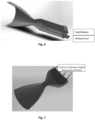
Fig. 5 , with marked manifolds supplying the components of the propellant mixture; - Fig. 7
- illustrates the construction of a rocket engine according to the invention with a cluster of individual staged detonation chambers, with a common afterburning chamber and an Aerospike nozzle;
- Fig. 8
- is a schematic diagram of the inventive conical rocket motor with staged detonation combustion;
- Fig. 9
- shows the layout diagrams of staged detonation combustion chambers in rocket engines according to the invention with an Aerospike nozzle, where:
Fig.9a ) shows a fragment of the annular staged detonation combustion chamber; andFig.9b) and Fig. 9c ) show a variant with a cluster of individual pre-detonation chambers feeding combustion products to the Aerospike nozzle. - In the drawings,
Figs. 1 to 4 illustrate the prior art discussed in more detail in the introductory part of this description. Against the background of these known solutions, the present invention shown inFigures 5 to 9c reveals all its advantages. - In the classical liquid propellant rocket engine shown in
Figs. 1 through Fig. 4 , the pre-combustion chamber provides energy to drive the fuel and oxidizer pumps. In order to maintain the temperature of the pre-combustion products adjusted to the permissible operating conditions of the turbine supplying energy to the fuel pump and the oxidizer, a propellant mixture with a composition differing from the stoichiometric composition, in which the fuel or oxidant predominates, is subjected to combustion, so that the combustion exhausts only a part of the excess component without until the maximum temperature of the combustion products is reached. According to the state of the art, the pre-combustion products, after supplementing the composition of the propellant mixture to the optimum parameters from the point of view of combustion in the main chamber of the rocket engine, are post-combusted in its main chamber. - In the solution according to the present invention, the spinning detonation process was used in the initial chamber of the rocket engine, obtaining a higher efficiency of the combustion process, resulting from the increase in pressure (the so-called Pressure Gain Combustion), compared to the classic deflagration combustion.
- According to the present invention, a staged detonation chamber is provided comprising at least two pre-chambers fed with different propellant mixtures - a fuel-rich mixture and an oxidant-rich mixture. These chambers are concentric to each other. In these chambers, incomplete combustion of the excess component takes place, as a result of which, at the exit of these chambers, a mixture of propellants of optimal composition is obtained, which is burnt in the post-combustion chamber located at the exit from the pre-combustion chambers. Exhaust gases leave the engine through the nozzle.
- This basic variant of the rocket engine according to the invention with a staged detonation chamber is illustrated in
Fig. 5 , where the oxidant-rich mixture is burned in an internal tubular detonation chamber 1 surrounded by an annular detonation chamber 2, in which the fuel-rich mixture is burned. At the exit of these two concentric chambers 1 and 2, there is acylindrical afterburner chamber 3, from which exhaust gases are discharged through anozzle 4. Red arrows indicate the supply to the combustion chambers of fuel, and blue arrows - the supply of oxidant. It is also possible to alternately supply the components of the propellant, then in the detonation chamber 1 a mixture rich in fuel is burned, and in the external detonation chamber 2 - a mixture rich in oxidant. The collectors of propellant components are shown inFig. 6 , where the remaining elements of the rocket engine with a staged detonation chamber are identical to those shown inFig. 5 . - The afterburning chamber in a rocket engine with a staged detonation chamber according to the invention is a deflagration chamber or preferably a detonation chamber.
- In
Figure 7 , a rocket engine according to the invention is shown having a cluster of individual staged detonation chambers as shown inFigures 5 and6 . Exhaust gases are discharged through a common nozzle. - Another embodiment of the invention is shown in
Fig. 8 , which shows a diagram of the construction of a conical, staged detonation combustion rocket engine. The detonation chamber 1 is intended for combustion of a mixture of propellant components enriched in oxidant, and the detonation chamber 2 - a mixture of propellant components enriched in fuel. Theafterburning chamber 3 is a classic (deflagration) or detonation chamber. The gases leave the engine throughnozzle 4. The arrows indicate the supply of propellant components: red - fuel, blue - oxidizer. -
Fig. 9 presents diagrams of the construction of chambers of gradual detonation combustion in rocket engines with an Aerospike nozzle. The annular staged detonation combustor (Fig. 9a ) has a detonation chamber 1 fed with an oxidant-rich mixture, a detonation chamber 2 fed with a fuel-rich mixture, apost-combustion chamber 3 being a conventional or detonation chamber.Nozzle 4 conducts a stream of exhaust gases over the outer surface of the Aerospike cone, which serves as one side of the virtual shield, while the other side is created by the air itself flowing around the moving rocket vehicle. When the air pressure changes with the flight altitude, the parameters of the virtual shield change. The engine automatically adjusts to altitude, compensating for the loss of engine power as altitude changes under various air pressure conditions, allowing the engine to maintain constant engine performance over a wide range of flight altitudes. - Also in this embodiment of the rocket engine according to the invention, variants with a cluster of individual staged detonation combustion chambers are provided (
Fig. 9b and Fig. 9c ), where the combustion products (exhaust gases) are discharged to the Aerospike nozzle. - In the rocket engine according to the invention, due to the very high energy density, the detonation chambers are much smaller and more compact, and as a result the engine is lighter. The use of the spinning detonation process makes it possible to improve the efficiency of the engine and increase the performance of rockets equipped with this type of turbine propulsion systems.
-
- 1. Sutton G. P., Biblarz O., Rocket propulsion elements, A Wiley-Interscience Publication JOHN WILEY & SONS, INC. New York / Chichester / Weinheim / Brisbane / Singapore / Toronto (7th ed. 2000);
- 2. https://en.wikipedia.org/wiki/Staged_combustion_cycle ;
- 3. Wolański P., "Detonative Propulsion", Proceedings of the Combustion Institute, 34, pp.125-158, Elsevier (2013);
- 4. Wolański P. (Ed.), "Research on detonative propulsion in Poland", Institute of Aviation Scientific Publication No. 60, Warsaw: Lukasiewicz Research Network - Institute of Aviation, 2021. ISBN 978-83-63539-45-0.
Claims (8)
- A rocket engine with the multi-stage combustion of a mixture of propellants, having at least one pre-combustion chamber and a main combustion chamber, a propellant mixture supply system to these chambers, including a fuel and oxidizer pumps, and an exhaust gas nozzle, characterized in that it has at least one staged detonation chamber, including at least two preliminary detonation chambers (1, 2), and at their outlet - a post-combustion chamber (3), where full mixing and post-combustion of detonation products from the pre-chambers (1, 2) takes place, and exhaust gases are directed outside through a nozzle (4), preferably of the Aerospike type.
- The rocket engine according to claim 1, characterized in that in the individual staged detonation chamber, the preliminary detonation chambers (1, 2) are concentric and have a tubular, annular, disc or conical structure and operate in the rotating detonation mode.
- The rocket engine according to claim 2, characterized in that the inner chamber has a tubular or conical structure.
- The rocket engine according to claim 1 or 2, characterized in that in the individual staged detonation chamber, one of the two preliminary detonation chambers (1, 2) is supplied with a fuel-rich gas mixture through a collector, and the second one - through another collector, with an oxidant-rich gas mixture.
- The rocket engine according to claim 1, characterized in that it has a deflagration afterburning chamber (3) in the individual staged detonation chamber.
- The rocket engine according to claim 1, characterized in that the afterburning chamber (3) is a detonation chamber.
- The rocket engine according to claim 1, characterized in that the individual staged detonation chambers are connected in clusters with a common discharge nozzle (4).
- The rocket engine according to claim 1, characterized in that the combustion products from the initial detonation chambers (1, 2) are directed to the turbines driving the fuel and oxidizer pumps.
Applications Claiming Priority (1)
| Application Number | Priority Date | Filing Date | Title |
|---|---|---|---|
| PL439872A PL244568B1 (en) | 2021-12-16 | 2021-12-16 | Rocket engine with multi-stage combustion of a mixture of propellants |
Publications (2)
| Publication Number | Publication Date |
|---|---|
| EP4202200A1 true EP4202200A1 (en) | 2023-06-28 |
| EP4202200B1 EP4202200B1 (en) | 2025-02-26 |
Family
ID=85238942
Family Applications (1)
| Application Number | Title | Priority Date | Filing Date |
|---|---|---|---|
| EP22020615.5A Active EP4202200B1 (en) | 2021-12-16 | 2022-12-16 | A rocket engine with multi-stage combustion of a mixture of propellants |
Country Status (2)
| Country | Link |
|---|---|
| EP (1) | EP4202200B1 (en) |
| PL (1) | PL244568B1 (en) |
Cited By (1)
| Publication number | Priority date | Publication date | Assignee | Title |
|---|---|---|---|---|
| CN118997950A (en) * | 2024-08-13 | 2024-11-22 | 中国人民解放军军事航天部队航天工程大学 | Rotary detonation rocket engine with staged combustion |
Citations (3)
| Publication number | Priority date | Publication date | Assignee | Title |
|---|---|---|---|---|
| US5873240A (en) * | 1993-04-14 | 1999-02-23 | Adroit Systems, Inc. | Pulsed detonation rocket engine |
| US6003301A (en) * | 1993-04-14 | 1999-12-21 | Adroit Systems, Inc. | Exhaust nozzle for multi-tube detonative engines |
| GB2468515A (en) * | 2009-03-09 | 2010-09-15 | Salahuddin Rasheedsedqi Saeed | Controllable thrust continuous detonation engine |
-
2021
- 2021-12-16 PL PL439872A patent/PL244568B1/en unknown
-
2022
- 2022-12-16 EP EP22020615.5A patent/EP4202200B1/en active Active
Patent Citations (3)
| Publication number | Priority date | Publication date | Assignee | Title |
|---|---|---|---|---|
| US5873240A (en) * | 1993-04-14 | 1999-02-23 | Adroit Systems, Inc. | Pulsed detonation rocket engine |
| US6003301A (en) * | 1993-04-14 | 1999-12-21 | Adroit Systems, Inc. | Exhaust nozzle for multi-tube detonative engines |
| GB2468515A (en) * | 2009-03-09 | 2010-09-15 | Salahuddin Rasheedsedqi Saeed | Controllable thrust continuous detonation engine |
Non-Patent Citations (3)
| Title |
|---|
| "Institute of Aviation Scientific Publication No. 60", 2021, LUKASIEWICZ RESEARCH NETWORK - INSTITUTE OF AVIATION, article "Research on detonative propulsion in Poland" |
| SUTTON G. P.BIBLARZ O.: "Rocket propulsion elements", 2000, JOHN WILEY & SONS |
| WOLANSKI P.: "Proceedings of the Combustion Institute", vol. 34, 2013, ELSEVIER, article "Detonative Propulsion", pages: 125 - 158 |
Cited By (1)
| Publication number | Priority date | Publication date | Assignee | Title |
|---|---|---|---|---|
| CN118997950A (en) * | 2024-08-13 | 2024-11-22 | 中国人民解放军军事航天部队航天工程大学 | Rotary detonation rocket engine with staged combustion |
Also Published As
| Publication number | Publication date |
|---|---|
| PL244568B1 (en) | 2024-02-12 |
| EP4202200B1 (en) | 2025-02-26 |
| PL439872A1 (en) | 2023-06-19 |
Similar Documents
| Publication | Publication Date | Title |
|---|---|---|
| US10641169B2 (en) | Hybrid combustor assembly and method of operation | |
| RU2331784C2 (en) | Pulsed detonation system for gas turbine engine and gas turbine engine incorporating such system | |
| US4845941A (en) | Gas turbine engine operating process | |
| US11287133B2 (en) | Axially staged rich quench lean combustion system | |
| US11149954B2 (en) | Multi-can annular rotating detonation combustor | |
| CN109028142A (en) | Propulsion system and the method for operating it | |
| EP4086991B1 (en) | Integrated fuel cell and engine combustor assembly | |
| US20060086078A1 (en) | Universal Carnot propulsion systems for turbo rocketry | |
| US20240376851A1 (en) | Turboshaft engine | |
| US7788899B2 (en) | Fixed nozzle thrust augmentation system | |
| EP4202200B1 (en) | A rocket engine with multi-stage combustion of a mixture of propellants | |
| US20240401807A1 (en) | Turbine engine including a combustor | |
| EP4155612B1 (en) | Pre-combustion chamber for feeding a turbine in a liquid propellant rocket engine | |
| AU3210384A (en) | Process of intensification of the thermoenergetical cycle andair jet propulsion engines | |
| US12130016B1 (en) | Turbine engine including a combustor | |
| US20240401808A1 (en) | Turbine Engine Including a Combustor | |
| US12352224B2 (en) | Serial rotating detonation combustor systems | |
| RU2493406C1 (en) | Liquid propellant rocket engine | |
| RU2490507C1 (en) | Liquid-propellant engine |
Legal Events
| Date | Code | Title | Description |
|---|---|---|---|
| PUAI | Public reference made under article 153(3) epc to a published international application that has entered the european phase |
Free format text: ORIGINAL CODE: 0009012 |
|
| STAA | Information on the status of an ep patent application or granted ep patent |
Free format text: STATUS: THE APPLICATION HAS BEEN PUBLISHED |
|
| AK | Designated contracting states |
Kind code of ref document: A1 Designated state(s): AL AT BE BG CH CY CZ DE DK EE ES FI FR GB GR HR HU IE IS IT LI LT LU LV MC ME MK MT NL NO PL PT RO RS SE SI SK SM TR |
|
| STAA | Information on the status of an ep patent application or granted ep patent |
Free format text: STATUS: REQUEST FOR EXAMINATION WAS MADE |
|
| 17P | Request for examination filed |
Effective date: 20231218 |
|
| RBV | Designated contracting states (corrected) |
Designated state(s): AL AT BE BG CH CY CZ DE DK EE ES FI FR GB GR HR HU IE IS IT LI LT LU LV MC ME MK MT NL NO PL PT RO RS SE SI SK SM TR |
|
| GRAP | Despatch of communication of intention to grant a patent |
Free format text: ORIGINAL CODE: EPIDOSNIGR1 |
|
| STAA | Information on the status of an ep patent application or granted ep patent |
Free format text: STATUS: GRANT OF PATENT IS INTENDED |
|
| INTG | Intention to grant announced |
Effective date: 20240918 |
|
| GRAS | Grant fee paid |
Free format text: ORIGINAL CODE: EPIDOSNIGR3 |
|
| GRAA | (expected) grant |
Free format text: ORIGINAL CODE: 0009210 |
|
| STAA | Information on the status of an ep patent application or granted ep patent |
Free format text: STATUS: THE PATENT HAS BEEN GRANTED |
|
| AK | Designated contracting states |
Kind code of ref document: B1 Designated state(s): AL AT BE BG CH CY CZ DE DK EE ES FI FR GB GR HR HU IE IS IT LI LT LU LV MC ME MK MT NL NO PL PT RO RS SE SI SK SM TR |
|
| REG | Reference to a national code |
Ref country code: GB Ref legal event code: FG4D |
|
| REG | Reference to a national code |
Ref country code: CH Ref legal event code: EP |
|
| REG | Reference to a national code |
Ref country code: DE Ref legal event code: R096 Ref document number: 602022010953 Country of ref document: DE |
|
| REG | Reference to a national code |
Ref country code: IE Ref legal event code: FG4D |
|
| REG | Reference to a national code |
Ref country code: NL Ref legal event code: MP Effective date: 20250226 |
|
| PG25 | Lapsed in a contracting state [announced via postgrant information from national office to epo] |
Ref country code: RS Free format text: LAPSE BECAUSE OF FAILURE TO SUBMIT A TRANSLATION OF THE DESCRIPTION OR TO PAY THE FEE WITHIN THE PRESCRIBED TIME-LIMIT Effective date: 20250526 |
|
| PG25 | Lapsed in a contracting state [announced via postgrant information from national office to epo] |
Ref country code: FI Free format text: LAPSE BECAUSE OF FAILURE TO SUBMIT A TRANSLATION OF THE DESCRIPTION OR TO PAY THE FEE WITHIN THE PRESCRIBED TIME-LIMIT Effective date: 20250226 |
|
| PG25 | Lapsed in a contracting state [announced via postgrant information from national office to epo] |
Ref country code: PL Free format text: LAPSE BECAUSE OF FAILURE TO SUBMIT A TRANSLATION OF THE DESCRIPTION OR TO PAY THE FEE WITHIN THE PRESCRIBED TIME-LIMIT Effective date: 20250226 |
|
| PG25 | Lapsed in a contracting state [announced via postgrant information from national office to epo] |
Ref country code: ES Free format text: LAPSE BECAUSE OF FAILURE TO SUBMIT A TRANSLATION OF THE DESCRIPTION OR TO PAY THE FEE WITHIN THE PRESCRIBED TIME-LIMIT Effective date: 20250226 |
|
| REG | Reference to a national code |
Ref country code: LT Ref legal event code: MG9D |
|
| PG25 | Lapsed in a contracting state [announced via postgrant information from national office to epo] |
Ref country code: NO Free format text: LAPSE BECAUSE OF FAILURE TO SUBMIT A TRANSLATION OF THE DESCRIPTION OR TO PAY THE FEE WITHIN THE PRESCRIBED TIME-LIMIT Effective date: 20250526 Ref country code: IS Free format text: LAPSE BECAUSE OF FAILURE TO SUBMIT A TRANSLATION OF THE DESCRIPTION OR TO PAY THE FEE WITHIN THE PRESCRIBED TIME-LIMIT Effective date: 20250626 |
|
| PG25 | Lapsed in a contracting state [announced via postgrant information from national office to epo] |
Ref country code: NL Free format text: LAPSE BECAUSE OF FAILURE TO SUBMIT A TRANSLATION OF THE DESCRIPTION OR TO PAY THE FEE WITHIN THE PRESCRIBED TIME-LIMIT Effective date: 20250226 |
|
| PG25 | Lapsed in a contracting state [announced via postgrant information from national office to epo] |
Ref country code: HR Free format text: LAPSE BECAUSE OF FAILURE TO SUBMIT A TRANSLATION OF THE DESCRIPTION OR TO PAY THE FEE WITHIN THE PRESCRIBED TIME-LIMIT Effective date: 20250226 |
|
| PG25 | Lapsed in a contracting state [announced via postgrant information from national office to epo] |
Ref country code: PT Free format text: LAPSE BECAUSE OF FAILURE TO SUBMIT A TRANSLATION OF THE DESCRIPTION OR TO PAY THE FEE WITHIN THE PRESCRIBED TIME-LIMIT Effective date: 20250626 Ref country code: LV Free format text: LAPSE BECAUSE OF FAILURE TO SUBMIT A TRANSLATION OF THE DESCRIPTION OR TO PAY THE FEE WITHIN THE PRESCRIBED TIME-LIMIT Effective date: 20250226 |
|
| PG25 | Lapsed in a contracting state [announced via postgrant information from national office to epo] |
Ref country code: GR Free format text: LAPSE BECAUSE OF FAILURE TO SUBMIT A TRANSLATION OF THE DESCRIPTION OR TO PAY THE FEE WITHIN THE PRESCRIBED TIME-LIMIT Effective date: 20250527 Ref country code: BG Free format text: LAPSE BECAUSE OF FAILURE TO SUBMIT A TRANSLATION OF THE DESCRIPTION OR TO PAY THE FEE WITHIN THE PRESCRIBED TIME-LIMIT Effective date: 20250226 |
|
| REG | Reference to a national code |
Ref country code: AT Ref legal event code: MK05 Ref document number: 1770827 Country of ref document: AT Kind code of ref document: T Effective date: 20250226 |
|
| PG25 | Lapsed in a contracting state [announced via postgrant information from national office to epo] |
Ref country code: SE Free format text: LAPSE BECAUSE OF FAILURE TO SUBMIT A TRANSLATION OF THE DESCRIPTION OR TO PAY THE FEE WITHIN THE PRESCRIBED TIME-LIMIT Effective date: 20250226 |
|
| PG25 | Lapsed in a contracting state [announced via postgrant information from national office to epo] |
Ref country code: SM Free format text: LAPSE BECAUSE OF FAILURE TO SUBMIT A TRANSLATION OF THE DESCRIPTION OR TO PAY THE FEE WITHIN THE PRESCRIBED TIME-LIMIT Effective date: 20250226 |
|
| PG25 | Lapsed in a contracting state [announced via postgrant information from national office to epo] |
Ref country code: DK Free format text: LAPSE BECAUSE OF FAILURE TO SUBMIT A TRANSLATION OF THE DESCRIPTION OR TO PAY THE FEE WITHIN THE PRESCRIBED TIME-LIMIT Effective date: 20250226 |
|
| PG25 | Lapsed in a contracting state [announced via postgrant information from national office to epo] |
Ref country code: IT Free format text: LAPSE BECAUSE OF FAILURE TO SUBMIT A TRANSLATION OF THE DESCRIPTION OR TO PAY THE FEE WITHIN THE PRESCRIBED TIME-LIMIT Effective date: 20250226 |
|
| PG25 | Lapsed in a contracting state [announced via postgrant information from national office to epo] |
Ref country code: AT Free format text: LAPSE BECAUSE OF FAILURE TO SUBMIT A TRANSLATION OF THE DESCRIPTION OR TO PAY THE FEE WITHIN THE PRESCRIBED TIME-LIMIT Effective date: 20250226 |
|
| PG25 | Lapsed in a contracting state [announced via postgrant information from national office to epo] |
Ref country code: EE Free format text: LAPSE BECAUSE OF FAILURE TO SUBMIT A TRANSLATION OF THE DESCRIPTION OR TO PAY THE FEE WITHIN THE PRESCRIBED TIME-LIMIT Effective date: 20250226 Ref country code: CZ Free format text: LAPSE BECAUSE OF FAILURE TO SUBMIT A TRANSLATION OF THE DESCRIPTION OR TO PAY THE FEE WITHIN THE PRESCRIBED TIME-LIMIT Effective date: 20250226 |
|
| PG25 | Lapsed in a contracting state [announced via postgrant information from national office to epo] |
Ref country code: RO Free format text: LAPSE BECAUSE OF FAILURE TO SUBMIT A TRANSLATION OF THE DESCRIPTION OR TO PAY THE FEE WITHIN THE PRESCRIBED TIME-LIMIT Effective date: 20250226 |
|
| PG25 | Lapsed in a contracting state [announced via postgrant information from national office to epo] |
Ref country code: SK Free format text: LAPSE BECAUSE OF FAILURE TO SUBMIT A TRANSLATION OF THE DESCRIPTION OR TO PAY THE FEE WITHIN THE PRESCRIBED TIME-LIMIT Effective date: 20250226 |
|
| REG | Reference to a national code |
Ref country code: DE Ref legal event code: R097 Ref document number: 602022010953 Country of ref document: DE |
|
| PLBE | No opposition filed within time limit |
Free format text: ORIGINAL CODE: 0009261 |
|
| STAA | Information on the status of an ep patent application or granted ep patent |
Free format text: STATUS: NO OPPOSITION FILED WITHIN TIME LIMIT |
|
| PGFP | Annual fee paid to national office [announced via postgrant information from national office to epo] |
Ref country code: DE Payment date: 20251210 Year of fee payment: 4 |
|
| PGFP | Annual fee paid to national office [announced via postgrant information from national office to epo] |
Ref country code: FR Payment date: 20251209 Year of fee payment: 4 |
|
| 26N | No opposition filed |
Effective date: 20251127 |