EP4202194A1 - After treatment heater system and control - Google Patents
After treatment heater system and control Download PDFInfo
- Publication number
- EP4202194A1 EP4202194A1 EP22216785.0A EP22216785A EP4202194A1 EP 4202194 A1 EP4202194 A1 EP 4202194A1 EP 22216785 A EP22216785 A EP 22216785A EP 4202194 A1 EP4202194 A1 EP 4202194A1
- Authority
- EP
- European Patent Office
- Prior art keywords
- temperature
- calculated
- catalytic converter
- internal combustion
- combustion engine
- Prior art date
- Legal status (The legal status is an assumption and is not a legal conclusion. Google has not performed a legal analysis and makes no representation as to the accuracy of the status listed.)
- Granted
Links
Images



Classifications
-
- F—MECHANICAL ENGINEERING; LIGHTING; HEATING; WEAPONS; BLASTING
- F01—MACHINES OR ENGINES IN GENERAL; ENGINE PLANTS IN GENERAL; STEAM ENGINES
- F01N—GAS-FLOW SILENCERS OR EXHAUST APPARATUS FOR MACHINES OR ENGINES IN GENERAL; GAS-FLOW SILENCERS OR EXHAUST APPARATUS FOR INTERNAL-COMBUSTION ENGINES
- F01N3/00—Exhaust or silencing apparatus having means for purifying, rendering innocuous, or otherwise treating exhaust
- F01N3/08—Exhaust or silencing apparatus having means for purifying, rendering innocuous, or otherwise treating exhaust for rendering innocuous
- F01N3/10—Exhaust or silencing apparatus having means for purifying, rendering innocuous, or otherwise treating exhaust for rendering innocuous by thermal or catalytic conversion of noxious components of exhaust
- F01N3/18—Exhaust or silencing apparatus having means for purifying, rendering innocuous, or otherwise treating exhaust for rendering innocuous by thermal or catalytic conversion of noxious components of exhaust characterised by methods of operation; Control
- F01N3/20—Exhaust or silencing apparatus having means for purifying, rendering innocuous, or otherwise treating exhaust for rendering innocuous by thermal or catalytic conversion of noxious components of exhaust characterised by methods of operation; Control specially adapted for catalytic conversion
- F01N3/206—Adding periodically or continuously substances to exhaust gases for promoting purification, e.g. catalytic material in liquid form, NOx reducing agents
- F01N3/208—Control of selective catalytic reduction [SCR], e.g. by adjusting the dosing of reducing agent
-
- F—MECHANICAL ENGINEERING; LIGHTING; HEATING; WEAPONS; BLASTING
- F01—MACHINES OR ENGINES IN GENERAL; ENGINE PLANTS IN GENERAL; STEAM ENGINES
- F01N—GAS-FLOW SILENCERS OR EXHAUST APPARATUS FOR MACHINES OR ENGINES IN GENERAL; GAS-FLOW SILENCERS OR EXHAUST APPARATUS FOR INTERNAL-COMBUSTION ENGINES
- F01N3/00—Exhaust or silencing apparatus having means for purifying, rendering innocuous, or otherwise treating exhaust
- F01N3/08—Exhaust or silencing apparatus having means for purifying, rendering innocuous, or otherwise treating exhaust for rendering innocuous
- F01N3/10—Exhaust or silencing apparatus having means for purifying, rendering innocuous, or otherwise treating exhaust for rendering innocuous by thermal or catalytic conversion of noxious components of exhaust
- F01N3/18—Exhaust or silencing apparatus having means for purifying, rendering innocuous, or otherwise treating exhaust for rendering innocuous by thermal or catalytic conversion of noxious components of exhaust characterised by methods of operation; Control
- F01N3/20—Exhaust or silencing apparatus having means for purifying, rendering innocuous, or otherwise treating exhaust for rendering innocuous by thermal or catalytic conversion of noxious components of exhaust characterised by methods of operation; Control specially adapted for catalytic conversion
- F01N3/2006—Periodically heating or cooling catalytic reactors, e.g. at cold starting or overheating
- F01N3/2013—Periodically heating or cooling catalytic reactors, e.g. at cold starting or overheating using electric or magnetic heating means
-
- F—MECHANICAL ENGINEERING; LIGHTING; HEATING; WEAPONS; BLASTING
- F01—MACHINES OR ENGINES IN GENERAL; ENGINE PLANTS IN GENERAL; STEAM ENGINES
- F01N—GAS-FLOW SILENCERS OR EXHAUST APPARATUS FOR MACHINES OR ENGINES IN GENERAL; GAS-FLOW SILENCERS OR EXHAUST APPARATUS FOR INTERNAL-COMBUSTION ENGINES
- F01N9/00—Electrical control of exhaust gas treating apparatus
-
- F—MECHANICAL ENGINEERING; LIGHTING; HEATING; WEAPONS; BLASTING
- F01—MACHINES OR ENGINES IN GENERAL; ENGINE PLANTS IN GENERAL; STEAM ENGINES
- F01N—GAS-FLOW SILENCERS OR EXHAUST APPARATUS FOR MACHINES OR ENGINES IN GENERAL; GAS-FLOW SILENCERS OR EXHAUST APPARATUS FOR INTERNAL-COMBUSTION ENGINES
- F01N2240/00—Combination or association of two or more different exhaust treating devices, or of at least one such device with an auxiliary device, not covered by indexing codes F01N2230/00 or F01N2250/00, one of the devices being
- F01N2240/14—Combination or association of two or more different exhaust treating devices, or of at least one such device with an auxiliary device, not covered by indexing codes F01N2230/00 or F01N2250/00, one of the devices being a fuel burner
-
- F—MECHANICAL ENGINEERING; LIGHTING; HEATING; WEAPONS; BLASTING
- F01—MACHINES OR ENGINES IN GENERAL; ENGINE PLANTS IN GENERAL; STEAM ENGINES
- F01N—GAS-FLOW SILENCERS OR EXHAUST APPARATUS FOR MACHINES OR ENGINES IN GENERAL; GAS-FLOW SILENCERS OR EXHAUST APPARATUS FOR INTERNAL-COMBUSTION ENGINES
- F01N2240/00—Combination or association of two or more different exhaust treating devices, or of at least one such device with an auxiliary device, not covered by indexing codes F01N2230/00 or F01N2250/00, one of the devices being
- F01N2240/16—Combination or association of two or more different exhaust treating devices, or of at least one such device with an auxiliary device, not covered by indexing codes F01N2230/00 or F01N2250/00, one of the devices being an electric heater, i.e. a resistance heater
-
- F—MECHANICAL ENGINEERING; LIGHTING; HEATING; WEAPONS; BLASTING
- F01—MACHINES OR ENGINES IN GENERAL; ENGINE PLANTS IN GENERAL; STEAM ENGINES
- F01N—GAS-FLOW SILENCERS OR EXHAUST APPARATUS FOR MACHINES OR ENGINES IN GENERAL; GAS-FLOW SILENCERS OR EXHAUST APPARATUS FOR INTERNAL-COMBUSTION ENGINES
- F01N2560/00—Exhaust systems with means for detecting or measuring exhaust gas components or characteristics
- F01N2560/02—Exhaust systems with means for detecting or measuring exhaust gas components or characteristics the means being an exhaust gas sensor
- F01N2560/026—Exhaust systems with means for detecting or measuring exhaust gas components or characteristics the means being an exhaust gas sensor for measuring or detecting NOx
-
- F—MECHANICAL ENGINEERING; LIGHTING; HEATING; WEAPONS; BLASTING
- F01—MACHINES OR ENGINES IN GENERAL; ENGINE PLANTS IN GENERAL; STEAM ENGINES
- F01N—GAS-FLOW SILENCERS OR EXHAUST APPARATUS FOR MACHINES OR ENGINES IN GENERAL; GAS-FLOW SILENCERS OR EXHAUST APPARATUS FOR INTERNAL-COMBUSTION ENGINES
- F01N2560/00—Exhaust systems with means for detecting or measuring exhaust gas components or characteristics
- F01N2560/06—Exhaust systems with means for detecting or measuring exhaust gas components or characteristics the means being a temperature sensor
-
- F—MECHANICAL ENGINEERING; LIGHTING; HEATING; WEAPONS; BLASTING
- F01—MACHINES OR ENGINES IN GENERAL; ENGINE PLANTS IN GENERAL; STEAM ENGINES
- F01N—GAS-FLOW SILENCERS OR EXHAUST APPARATUS FOR MACHINES OR ENGINES IN GENERAL; GAS-FLOW SILENCERS OR EXHAUST APPARATUS FOR INTERNAL-COMBUSTION ENGINES
- F01N2570/00—Exhaust treating apparatus eliminating, absorbing or adsorbing specific elements or compounds
- F01N2570/14—Nitrogen oxides
-
- F—MECHANICAL ENGINEERING; LIGHTING; HEATING; WEAPONS; BLASTING
- F01—MACHINES OR ENGINES IN GENERAL; ENGINE PLANTS IN GENERAL; STEAM ENGINES
- F01N—GAS-FLOW SILENCERS OR EXHAUST APPARATUS FOR MACHINES OR ENGINES IN GENERAL; GAS-FLOW SILENCERS OR EXHAUST APPARATUS FOR INTERNAL-COMBUSTION ENGINES
- F01N2900/00—Details of electrical control or of the monitoring of the exhaust gas treating apparatus
- F01N2900/04—Methods of control or diagnosing
- F01N2900/0416—Methods of control or diagnosing using the state of a sensor, e.g. of an exhaust gas sensor
-
- F—MECHANICAL ENGINEERING; LIGHTING; HEATING; WEAPONS; BLASTING
- F01—MACHINES OR ENGINES IN GENERAL; ENGINE PLANTS IN GENERAL; STEAM ENGINES
- F01N—GAS-FLOW SILENCERS OR EXHAUST APPARATUS FOR MACHINES OR ENGINES IN GENERAL; GAS-FLOW SILENCERS OR EXHAUST APPARATUS FOR INTERNAL-COMBUSTION ENGINES
- F01N2900/00—Details of electrical control or of the monitoring of the exhaust gas treating apparatus
- F01N2900/04—Methods of control or diagnosing
- F01N2900/0418—Methods of control or diagnosing using integration or an accumulated value within an elapsed period
-
- F—MECHANICAL ENGINEERING; LIGHTING; HEATING; WEAPONS; BLASTING
- F01—MACHINES OR ENGINES IN GENERAL; ENGINE PLANTS IN GENERAL; STEAM ENGINES
- F01N—GAS-FLOW SILENCERS OR EXHAUST APPARATUS FOR MACHINES OR ENGINES IN GENERAL; GAS-FLOW SILENCERS OR EXHAUST APPARATUS FOR INTERNAL-COMBUSTION ENGINES
- F01N2900/00—Details of electrical control or of the monitoring of the exhaust gas treating apparatus
- F01N2900/06—Parameters used for exhaust control or diagnosing
- F01N2900/0602—Electrical exhaust heater signals
-
- F—MECHANICAL ENGINEERING; LIGHTING; HEATING; WEAPONS; BLASTING
- F01—MACHINES OR ENGINES IN GENERAL; ENGINE PLANTS IN GENERAL; STEAM ENGINES
- F01N—GAS-FLOW SILENCERS OR EXHAUST APPARATUS FOR MACHINES OR ENGINES IN GENERAL; GAS-FLOW SILENCERS OR EXHAUST APPARATUS FOR INTERNAL-COMBUSTION ENGINES
- F01N2900/00—Details of electrical control or of the monitoring of the exhaust gas treating apparatus
- F01N2900/06—Parameters used for exhaust control or diagnosing
- F01N2900/14—Parameters used for exhaust control or diagnosing said parameters being related to the exhaust gas
- F01N2900/1404—Exhaust gas temperature
-
- F—MECHANICAL ENGINEERING; LIGHTING; HEATING; WEAPONS; BLASTING
- F01—MACHINES OR ENGINES IN GENERAL; ENGINE PLANTS IN GENERAL; STEAM ENGINES
- F01N—GAS-FLOW SILENCERS OR EXHAUST APPARATUS FOR MACHINES OR ENGINES IN GENERAL; GAS-FLOW SILENCERS OR EXHAUST APPARATUS FOR INTERNAL-COMBUSTION ENGINES
- F01N2900/00—Details of electrical control or of the monitoring of the exhaust gas treating apparatus
- F01N2900/06—Parameters used for exhaust control or diagnosing
- F01N2900/16—Parameters used for exhaust control or diagnosing said parameters being related to the exhaust apparatus, e.g. particulate filter or catalyst
- F01N2900/1602—Temperature of exhaust gas apparatus
-
- F—MECHANICAL ENGINEERING; LIGHTING; HEATING; WEAPONS; BLASTING
- F01—MACHINES OR ENGINES IN GENERAL; ENGINE PLANTS IN GENERAL; STEAM ENGINES
- F01N—GAS-FLOW SILENCERS OR EXHAUST APPARATUS FOR MACHINES OR ENGINES IN GENERAL; GAS-FLOW SILENCERS OR EXHAUST APPARATUS FOR INTERNAL-COMBUSTION ENGINES
- F01N2900/00—Details of electrical control or of the monitoring of the exhaust gas treating apparatus
- F01N2900/06—Parameters used for exhaust control or diagnosing
- F01N2900/16—Parameters used for exhaust control or diagnosing said parameters being related to the exhaust apparatus, e.g. particulate filter or catalyst
- F01N2900/1626—Catalyst activation temperature
-
- F—MECHANICAL ENGINEERING; LIGHTING; HEATING; WEAPONS; BLASTING
- F01—MACHINES OR ENGINES IN GENERAL; ENGINE PLANTS IN GENERAL; STEAM ENGINES
- F01N—GAS-FLOW SILENCERS OR EXHAUST APPARATUS FOR MACHINES OR ENGINES IN GENERAL; GAS-FLOW SILENCERS OR EXHAUST APPARATUS FOR INTERNAL-COMBUSTION ENGINES
- F01N2900/00—Details of electrical control or of the monitoring of the exhaust gas treating apparatus
- F01N2900/06—Parameters used for exhaust control or diagnosing
- F01N2900/16—Parameters used for exhaust control or diagnosing said parameters being related to the exhaust apparatus, e.g. particulate filter or catalyst
- F01N2900/1631—Heat amount provided to exhaust apparatus
-
- F—MECHANICAL ENGINEERING; LIGHTING; HEATING; WEAPONS; BLASTING
- F01—MACHINES OR ENGINES IN GENERAL; ENGINE PLANTS IN GENERAL; STEAM ENGINES
- F01N—GAS-FLOW SILENCERS OR EXHAUST APPARATUS FOR MACHINES OR ENGINES IN GENERAL; GAS-FLOW SILENCERS OR EXHAUST APPARATUS FOR INTERNAL-COMBUSTION ENGINES
- F01N3/00—Exhaust or silencing apparatus having means for purifying, rendering innocuous, or otherwise treating exhaust
- F01N3/08—Exhaust or silencing apparatus having means for purifying, rendering innocuous, or otherwise treating exhaust for rendering innocuous
- F01N3/10—Exhaust or silencing apparatus having means for purifying, rendering innocuous, or otherwise treating exhaust for rendering innocuous by thermal or catalytic conversion of noxious components of exhaust
- F01N3/18—Exhaust or silencing apparatus having means for purifying, rendering innocuous, or otherwise treating exhaust for rendering innocuous by thermal or catalytic conversion of noxious components of exhaust characterised by methods of operation; Control
- F01N3/20—Exhaust or silencing apparatus having means for purifying, rendering innocuous, or otherwise treating exhaust for rendering innocuous by thermal or catalytic conversion of noxious components of exhaust characterised by methods of operation; Control specially adapted for catalytic conversion
- F01N3/2006—Periodically heating or cooling catalytic reactors, e.g. at cold starting or overheating
- F01N3/2013—Periodically heating or cooling catalytic reactors, e.g. at cold starting or overheating using electric or magnetic heating means
- F01N3/2026—Periodically heating or cooling catalytic reactors, e.g. at cold starting or overheating using electric or magnetic heating means directly electrifying the catalyst substrate, i.e. heating the electrically conductive catalyst substrate by joule effect
-
- F—MECHANICAL ENGINEERING; LIGHTING; HEATING; WEAPONS; BLASTING
- F01—MACHINES OR ENGINES IN GENERAL; ENGINE PLANTS IN GENERAL; STEAM ENGINES
- F01N—GAS-FLOW SILENCERS OR EXHAUST APPARATUS FOR MACHINES OR ENGINES IN GENERAL; GAS-FLOW SILENCERS OR EXHAUST APPARATUS FOR INTERNAL-COMBUSTION ENGINES
- F01N9/00—Electrical control of exhaust gas treating apparatus
- F01N9/005—Electrical control of exhaust gas treating apparatus using models instead of sensors to determine operating characteristics of exhaust systems, e.g. calculating catalyst temperature instead of measuring it directly
-
- Y—GENERAL TAGGING OF NEW TECHNOLOGICAL DEVELOPMENTS; GENERAL TAGGING OF CROSS-SECTIONAL TECHNOLOGIES SPANNING OVER SEVERAL SECTIONS OF THE IPC; TECHNICAL SUBJECTS COVERED BY FORMER USPC CROSS-REFERENCE ART COLLECTIONS [XRACs] AND DIGESTS
- Y02—TECHNOLOGIES OR APPLICATIONS FOR MITIGATION OR ADAPTATION AGAINST CLIMATE CHANGE
- Y02T—CLIMATE CHANGE MITIGATION TECHNOLOGIES RELATED TO TRANSPORTATION
- Y02T10/00—Road transport of goods or passengers
- Y02T10/10—Internal combustion engine [ICE] based vehicles
- Y02T10/12—Improving ICE efficiencies
Definitions
- Typical components of such an aftertreatment system may be a diesel particulate filter to capture soot, and a catalytic converter more specifically an SCR (Selective Catalytic Reduction) catalyst that converts NOx into harmless products also known as the deNOx process and a diesel oxidation catalyst (DOC) to (inter alia) increase de deNOX efficiency and oxydize unburned hydrocarbon.
- Aftertreatment systems may further include a heater system, such as an electric heater system, diesel burner or a diesel oxidation catalyst (DOC) in combination with a HC-doser or elevated hydrocarbon levels.
- DOC diesel oxidation catalyst
- the heater system may be used to heat the aftertreatment system to an operating temperature, which may be around 200-300 °C.
- the aftertreatment system can be heated by residual heat from the combustion engine, however, at very low loads, the temperature of the exhaust gas may be too low.
- the temperature may be influenced by an engine efficiency mode, which controls the efficiency of the engine and an engine out temperature. For high efficiency engine power settings, the temperature may be too low to accommodate a required NOx conversion efficiency of the catalytic converter, in which case the engine aftertreatment system temperature should be increased.
- the operating temperature of the aftertreatment system is dependent on the energy content of the exhaust gas, generated by the ICE.
- changes in the energy content, i.e. exhaust gas enthalpy, of the exhaust gas will be the root cause for a changing aftertreatment operating temperature, that may result in different SCR conversion rates.
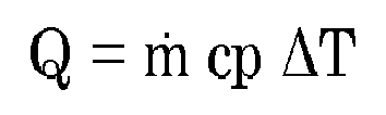
- the exhaust gas enthalpy is calculated by:
- the engine aftertreatment system contains components with a relatively high thermal mass. Therefore the operating temperature of the system cannot be changed rapidly under varying driving conditions. Therefore, conventionally, the aftertreatment operating temperature is controlled to a temperature which can result in robust deNOx control, irrespective of its required conversion efficiency. This comes at a CO2 cost when the amount of fuel is increased.
- an internal combustion engine comprising: a heater system disposed in or near an exhaust aftertreatment system including a catalytic converter to generate heat to the exhaust aftertreatment system; a control system arranged to control the heater system; wherein the control system is programmed to calculate an enthalpy difference of an actual measured exhaust gas enthalpy signal and a time filtered exhaust gas enthalpy signal. When a calculated enthalpy difference signal value is lower than a set threshold value, the control system activates the heater system to generate a catalytic converter temperature to a calculated set target temperature of the catalytic converter, based on a calculated or measured engine NOx output level and a target NOx output level.
- the specific position of the heater system may be dependent on practical conditions. It may be a system that can be integral to the aftertreatment system.
- the aftertreatment system may be timely heated to an increased conversion efficiency of the engine aftertreatment system at higher temperature.
- the invention obviates a necessity to keep the catalytic converter at high conversion efficiency temperature at all times, in order to cope with dynamic transient behaviour of the engine. According to the invention, in a steady state engine condition, i.e.
- a lower aftertreatment temperature may be accepted that is yet optimal, minimizes a fuel cost and is based on a calculated or measured engine NOx output level, thus allowing for reduced CO2 emissions due to reduced activation of the heater system.
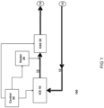
- FIG. 1 shows a simplified schematic representation of a system setup 100 of an internal combustion engine (ICE 10) and a typical aftertreatment system (EAS 30).
- the EAS system may comprise a hydrocarbon (HC) dosing unit, a Diesel Oxidation Catalyst (DOC), a Diesel Particulate Filter (DPF), a Urea dosing unit, a Selective Catalytic Reduction catalyst (SCR), an Ammonia Slip Catalyst (ASC) and a Control Module (CM) placed downstream in the exhaust line 13 of the ICE 10 typically including a turbo compressor.
- This setup is conventional, in the sense that the system elements are known to the skilled person.
- EAS control 50 in Figure 1 can be provided on the basis of NOx sensor data or a model.
- Internal combustion engine (ICE 10) comprises an exhaust line 13 configured to receive exhaust gas from the internal combustion engine 10 and an intake line 12 configured to supply pressurized air from an air intake 14 to the internal combustion engine 10.
- a heater system 20 is disposed in or adjacent the exhaust line 13 to generate heat that is transported via the exhaust line 13 to an exhaust aftertreatment system (EAS) 30.
- a control system 50 is arranged to control the heater system 20 to transport heat generated by the heater system 20 towards EAS 30.
- the heater system 20 may also be activated.
- Heater system 20 may be an electric heater system or it may be a burner or other heat source.
- a turbo can be controlled to achieve certain boost pressure for the engine intake line 12 and may be a turbo compressor of a known type, where mechanical energy derived from the exhaust turbine may be electrically boosted by an electric motor.
- the compressor may also be all-electric or may be hybrid - that is, the compressor can be mechanically driven by the turbine and at the same time boosted by an electric motor.
- the control system 50 may calculate the heat addition delivered by the heater system/burner. This can be determined by a temperature sensor or a model, in view of the exhaust gas flow, that is provided by the heater system 20.
- the exhaust mass flow is normally limited to ⁇ 20-50 g/s, which is lower than e.g. a desired 100g/s.
- the exhaust gas temperature upstream of a heater system/heater system can be in the range of 100-150 degC, or even colder in the case of a cold-start event.
- the maximum heat enthalpy may be limited to about 5 kW, which is below a typical capacity of a heater system, which could be in the order of 8-30 kW, e.g. 10 kW.
- the exhaust flow may be increased to increase heat transport out of the heater and to prevent the heater system exceeding a maximum temperature.
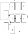
- an internal combustion engine 10 is illustrated with a conventional turbo compressor arrangement, i.e. a turbine 18 arranged in the exhaust line 13, that is mechanically coupled to a compressor 400 via a turbo shaft 19.
- the compressor can be of a conventional type.
- the compressor 400 boosts the pressure, via a charge air cooler 402 into the engine 10. If a control system detects that the EAS 30 is in need for additional heating , heater system, e.g. diesel burner 20 is activated, to generate a catalytic converter temperature to a calculated set target temperature of the catalytic converter. This can be executed by a feed forward control, e.g.
- a control system implemented in hardware or software in a control system, geared to a standard acceptable flow provided to the heater system 20 that allows the heater system to heat at its maximum heater system capacity. It can also in a feedback loop control, e.g. by a flow controlled process, that increases the fuel in dependence of increased flow in the exhaust line 13 or by a temperature controlled process, that increases the flow in dependence of a measured or calculated threshold temperature of the heater system 20 adjacent the exhaust line 13. Since heat transfer is most efficient at high temperatures, this latter option is a preferred mode.
- an e-turbo may be arranged in the intake line 12, that is mechanically driven by turboshaft 19, but can also be powered by an electromotor.
- the e-turbo is arranged in a fluid communication path in intake line 12 between the air intake 15.
- the internal combustion engine 10 may comprise an exhaust gas recirculation (egr) line 11 for use, in egr mode, to supply exhaust gas to the intake line 12.
- egr exhaust gas recirculation
- Figure 3 further exemplifies a control scheme 500 executed by control system 50 (see Figure 1 ) for selective control of the heater system 20 for generating heat generated by the heater system towards the aftertreatment system.
- the control flow has a control decision mode 51 that continuously or at least at intermittent intervals queries an available heat enthalpy Q from the exhaust gas. This can be done by measuring, temperature, pressure and a flow, essentially, or using engine parameters that will provide equivalent results or estimations known to a skilled person. Such a query may be dependent on vehicle state operations such as engine temperature, engine load and may be active in initial stages of an engine control after cold start.
- TRA transient indicator
- the transient indicator TRA shows an increased transient level of exhaust gas energy, it will go to a robust constant aftertreatment operating temperature target Tm of e.g. higher than 200-250 deg Celsius.
- the controller 500 may calculate a variable SCR target temperature based on the transient indicator in block 52.
- One optimization strategy may be using a set of fixed, lower temperature settings, via a calibration routine that correlates a transient indicator to a set target temperature Tt.
- Figure 4A and 4B show exemplary traces of a dynamic cycle and a steady state cycle respectively.
- an actual measured enthalpy Q and a time filtered enthalpy Qfltr are shown, together with a measured temperature TeaSCR.
- the temperature is measured downstream the heater - eg. just before, at or after the catalytic converter.
- the measured temperature substantially follows the time filtered exhaust gas enthalpy signal, which is thus a good predictor of the temperature profile of the catalytic converter.
- a model may be formed by a calibratable lookup table, of which an exemplary view is shown in Figure 5A .
- This model outputs a variable target SCR bed temperature Tt.
- the model may include a temperature drop estimation of all the aftertreatment components between the SCR and the heating element introduced which can be captured by a look-up table (fed with the engine massflow and the ambient temperature). Accordingly a heater target temperature may be calculated as a function of a temperature drop of a measured exhaust gas.
- the SCR efficiency target may be determined differently for two operational cases:
- NO x spec N O ⁇ x M ⁇ ⁇ 3600
- NO x spec N O ⁇ x ⁇ 3600
- the SCR efficiency target ⁇ may be defined by the specific NOx target and a calibratable NOx target in g/kWh for driving operation and a target in g/h for idle operation.
- ⁇ 1 ⁇ NO x trgt NO x spec
- an inverse model may provide a target temperature Tt which can be used in an optional closed loop control logic 53.
- a feedforward enthalpy gap can be calculated with respect to the difference between the temperature target and the engine outlet temperature measured at 54. The enthalpy loss is given by Where
- Figure 5B shows a practical example flow chart wherein input values 1-4 are provided as
- a difference is provided by a substractor resulting ⁇ T: Temperature difference between the exhaust gas and ambient.
- a multiplicator is provided for multiplying the resultant ⁇ T with input values 2 and 4, amounting to a calculated heat enthalpy of the exhaust gas.
- a time discrete filter is provided, with a filter constant e.g. of 1-5 seconds, preferably 2 seconds.
- a subtractor is provided that substracts the calculated heat enthalpy with the time filtered enthalpy, resulting in an absolute value of transient level error signal
- a flag is rased that a steady state is reached when the time error signal u is smaller than the set calibration threshold for e.g. about 50-150 seconds.
- Figure 6 shows a further flow diagram, of control steps executed by a controller, eg. of the type disclosed in Figure 1 for providing a calibratable target temperature of the catalytic converter to a calculated set target temperature of the catalytic converter, based on a calculated or measured engine NOx output level in a first engine state C5, or, in a second engine state C7, to a fixed robust target temperature that is higher than the converter temperature in the first engine state C5.
- a first control step S1 may check whether the engine is in an engine brake or motoring condition. If yes, due to absence of combustion, an alternative heater strategy C1 may be used e.g. if the thermal measure is directly powered by flywheel power.
- a precheck is executed whether the after treatment system is already in a heated state, obviating control of the heater system. If no, the aftertreatment system may be conventionally heated using full power of the e-heater that may be limited by the exhaust mass flow in condition C2. If yes, engine after treatment system is in a keep warm control state. In step S3, it may be checked whether the engine (while the engine after treatment system is in heated state) is still in a heat up condition or a fuel conversion mode wherein the amount of produced NOx is relatively low. If no, a control step S6 may be executed to check whether the heater may be used in a regeneration mode. If no, the heater may be switched off in condition C3.
- a regeneration program may be executed in condition C4. If, in step S3 it is found that the engine is in a heat up condition or in a low NOx (e.g: less efficient) engine efficiency mode; in step S4 it may be tested whether the engine is in an idle mode; e.g. idling sufficiently long so that the exhaust temperature will become too low; which may be controlled in a different manner, e.g. a converter temperature may be set according to a calibratable target temperature that may be controlled by a heater control loop.
- a low NOx e.g: less efficient
- control system 500 calculates an enthalpy difference of an actual exhaust gas enthalpy signal and a time filtered exhaust gas enthalpy signal, wherein, when a calculated enthalpy difference signal is lower than a set threshold value, the control system activates the heater system, after a predetermined set time duration, to generate a catalytic converter temperature to a calculated set target temperature of the catalytic converter, based on an engine NOx output level and a target NOx output level in, steady state condition condition C6.
- step S5 If in step S5 the calculated enthalpy difference is found higher than a set threshold value, in step S5 a transient condition C7 is controlled wherein the control system activates the heater system to generate an elevated catalytic converter temperature higher than the calculated set target temperature that is robust for substantial variation of NOx output values in a more transient condition. It is noted that steps S1-S4 non-essential prechecks that are merely exemplary to illustrate how inventive controller 500 can be combined with other control steps.
Landscapes
- Engineering & Computer Science (AREA)
- Chemical & Material Sciences (AREA)
- Chemical Kinetics & Catalysis (AREA)
- Combustion & Propulsion (AREA)
- Mechanical Engineering (AREA)
- General Engineering & Computer Science (AREA)
- Health & Medical Sciences (AREA)
- Toxicology (AREA)
- Exhaust Gas After Treatment (AREA)
Abstract
Description
- In modern day diesel engines, measures are taken to minimize fuel consumption and harmful emissions. The emissions of diesel soot and NOx can be reduced in an engine aftertreatment system (EAS). Typical components of such an aftertreatment system may be a diesel particulate filter to capture soot, and a catalytic converter more specifically an SCR (Selective Catalytic Reduction) catalyst that converts NOx into harmless products also known as the deNOx process and a diesel oxidation catalyst (DOC) to (inter alia) increase de deNOX efficiency and oxydize unburned hydrocarbon. Aftertreatment systems may further include a heater system, such as an electric heater system, diesel burner or a diesel oxidation catalyst (DOC) in combination with a HC-doser or elevated hydrocarbon levels. Typically the reactivity of aftertreatment systems increases when temperature of the catalyst material and the exhaust gas increases at least up to a certain temperature. In order to quickly reach a high conversion efficiency of the aftertreatment system after engine start, the heater system may be used to heat the aftertreatment system to an operating temperature, which may be around 200-300 °C. In normal operation, the aftertreatment system can be heated by residual heat from the combustion engine, however, at very low loads, the temperature of the exhaust gas may be too low. The temperature may be influenced by an engine efficiency mode, which controls the efficiency of the engine and an engine out temperature. For high efficiency engine power settings, the temperature may be too low to accommodate a required NOx conversion efficiency of the catalytic converter, in which case the engine aftertreatment system temperature should be increased.
- The operating temperature of the aftertreatment system is dependent on the energy content of the exhaust gas, generated by the ICE. In other words, changes in the energy content, i.e. exhaust gas enthalpy, of the exhaust gas, will be the root cause for a changing aftertreatment operating temperature, that may result in different SCR conversion rates. The exhaust gas enthalpy is calculated by:
- Q =
- Exhaust gas enthalpy
- ṁ =
- Exhaust gas massflow
- cp =
- Specific heat of gas at constant pressure
- ΔT =
- Temperature difference between the exhaust gas and ambient
- However, the engine aftertreatment system contains components with a relatively high thermal mass. Therefore the operating temperature of the system cannot be changed rapidly under varying driving conditions. Therefore, conventionally, the aftertreatment operating temperature is controlled to a temperature which can result in robust deNOx control, irrespective of its required conversion efficiency. This comes at a CO2 cost when the amount of fuel is increased.
- It is an object of the invention to more efficiently control the heater system, while at the same time generate an amount of enthalpy necessary for a sufficient SCR conversion.
- It is an aspect of the present invention to alleviate, at least partially, the problems discussed above by an internal combustion engine comprising: a heater system disposed in or near an exhaust aftertreatment system including a catalytic converter to generate heat to the exhaust aftertreatment system;
a control system arranged to control the heater system; wherein the control system is programmed to calculate an enthalpy difference of an actual measured exhaust gas enthalpy signal and a time filtered exhaust gas enthalpy signal. When a calculated enthalpy difference signal value is lower than a set threshold value, the control system activates the heater system to generate a catalytic converter temperature to a calculated set target temperature of the catalytic converter, based on a calculated or measured engine NOx output level and a target NOx output level. - By using the time filtered enthalpy signal accordingly it is found that a reliable indicator of the catalytic converter temperature profile can be provided, that is able to display a corresponding dynamic behaviour as a future catalytic converter temperature. Conversely, it can be predicted that a catalytic converter temperature will change when a calculated enthalpy difference signal value is higher than a set threshold value.
- The specific position of the heater system may be dependent on practical conditions. It may be a system that can be integral to the aftertreatment system.
- Additionally, it can be identified that a prolonged transient driving condition of the engine exists, in which case the aftertreatment system may be timely heated to an increased conversion efficiency of the engine aftertreatment system at higher temperature. At the same time, there will be a reduced CO2 penalty for increasing the aftertreatment temperature when a higher temperature is not necessary. The invention obviates a necessity to keep the catalytic converter at high conversion efficiency temperature at all times, in order to cope with dynamic transient behaviour of the engine. According to the invention, in a steady state engine condition, i.e. a condition where a difference between an actual measured exhaust gas enthalpy and a time filtered exhaust gas enthalpy is lower than a set threshold value, a lower aftertreatment temperature may be accepted that is yet optimal, minimizes a fuel cost and is based on a calculated or measured engine NOx output level, thus allowing for reduced CO2 emissions due to reduced activation of the heater system.
- The accompanying drawings, which are incorporated herein and form part of the specification, illustrate the present invention and, together with the description, further serve to explain the principles of the invention and to enable a person skilled in the relevant art(s) to make and use the invention.
-
Figure 1 shows a simplified schematic representation of a system setup of an internal combustion engine; -
Figure 2 an shows an embodiment with a conventional turbo compressor arrangement; -
Figure 3 further exemplifies a control scheme executed by the control system of seeFigure 1 ; -
Figure 4A and 4B show exemplary traces of a dynamic cycle and a steady state cycle respectively; -
Figure 5 (A, B) shows an exemplary example of an inverse SCR model; -
Figure 6 shows a further implementation of the inventive heater control; - Unless otherwise defined, all terms (including technical and scientific terms) used herein have the same meaning as commonly understood by one of ordinary skill in the art to which this invention belongs as read in the context of the description and drawings. It will be further understood that terms, such as those defined in commonly used dictionaries, should be interpreted as having a meaning that is consistent with their meaning in the context of the relevant art and will not be interpreted in an idealized or overly formal sense unless expressly so defined herein. In some instances, detailed descriptions of well-known devices and methods may be omitted so as not to obscure the description of the present systems and methods. The term "and/or" includes any and all combinations of one or more of the associated listed items. It will be further understood that the terms "comprises" and/or "comprising" specify the presence of stated features but do not preclude the presence or addition of one or more other features. All publications, patent applications, patents, and other references mentioned herein are incorporated by reference in their entirety. In case of conflict, the present specification, including definitions, will control.
-
Figure 1 shows a simplified schematic representation of asystem setup 100 of an internal combustion engine (ICE 10) and a typical aftertreatment system (EAS 30). The EAS system may comprise a hydrocarbon (HC) dosing unit, a Diesel Oxidation Catalyst (DOC), a Diesel Particulate Filter (DPF), a Urea dosing unit, a Selective Catalytic Reduction catalyst (SCR), an Ammonia Slip Catalyst (ASC) and a Control Module (CM) placed downstream in theexhaust line 13 of the ICE 10 typically including a turbo compressor. This setup is conventional, in the sense that the system elements are known to the skilled person. EAScontrol 50 inFigure 1 can be provided on the basis of NOx sensor data or a model. This means that this sensor is used indicatively for the control of NOx out of the system, and therefore for the dosing of DEF fluid, which implies the functioning of part of the EAS. In addition, in addition to a NOx sensor, other sensors may be used, for example flow sensors, chemical substance sensors, etc., that can indicate whether the aftertreatment system is affected by degradation. Internal combustion engine (ICE 10) comprises anexhaust line 13 configured to receive exhaust gas from theinternal combustion engine 10 and anintake line 12 configured to supply pressurized air from anair intake 14 to theinternal combustion engine 10. Aheater system 20 is disposed in or adjacent theexhaust line 13 to generate heat that is transported via theexhaust line 13 to an exhaust aftertreatment system (EAS) 30. Acontrol system 50 is arranged to control theheater system 20 to transport heat generated by theheater system 20 towards EAS 30. - During cold start or in other conditions where the operating temperature of the EAS 30 is insufficient, the
heater system 20 may also be activated.Heater system 20 may be an electric heater system or it may be a burner or other heat source. A turbo can be controlled to achieve certain boost pressure for theengine intake line 12 and may be a turbo compressor of a known type, where mechanical energy derived from the exhaust turbine may be electrically boosted by an electric motor. The compressor may also be all-electric or may be hybrid - that is, the compressor can be mechanically driven by the turbine and at the same time boosted by an electric motor. Thecontrol system 50 may calculate the heat addition delivered by the heater system/burner. This can be determined by a temperature sensor or a model, in view of the exhaust gas flow, that is provided by theheater system 20. - By physical law:

- Q_heater system =
- Exhaust gas enthalpy addition by the heater system
- ṁ =
- Exhaust gas massflow
- cp =
- Specific heat of gas at constant pressure
- exh_temp_ab =
- Exhaust gas temperature downstream of heater system/heater system
- exh_temp bb =
- Exhaust gas temperature upstream of heater system/heater system
- As a non limiting example, e.g. during engine idling the exhaust mass flow is normally limited to ~20-50 g/s, which is lower than e.g. a desired 100g/s. in such cases also, the exhaust gas temperature upstream of a heater system/heater system can be in the range of 100-150 degC, or even colder in the case of a cold-start event. In such a condition taking into account a maximum temperature tolerance of the heater system or engine after treatment system, the maximum heat enthalpy may be limited to about 5 kW, which is below a typical capacity of a heater system, which could be in the order of 8-30 kW, e.g. 10 kW. To be able to deliver the heat power while keeping the temperature in acceptable limits, the exhaust flow may be increased to increase heat transport out of the heater and to prevent the heater system exceeding a maximum temperature.
- Turning to
Figure 2 aninternal combustion engine 10 is illustrated with a conventional turbo compressor arrangement, i.e. aturbine 18 arranged in theexhaust line 13, that is mechanically coupled to acompressor 400 via aturbo shaft 19. In this example, the compressor can be of a conventional type. Thecompressor 400 boosts the pressure, via acharge air cooler 402 into theengine 10. If a control system detects that theEAS 30 is in need for additional heating , heater system,e.g. diesel burner 20 is activated, to generate a catalytic converter temperature to a calculated set target temperature of the catalytic converter. This can be executed by a feed forward control, e.g. implemented in hardware or software in a control system, geared to a standard acceptable flow provided to theheater system 20 that allows the heater system to heat at its maximum heater system capacity. It can also in a feedback loop control, e.g. by a flow controlled process, that increases the fuel in dependence of increased flow in theexhaust line 13 or by a temperature controlled process, that increases the flow in dependence of a measured or calculated threshold temperature of theheater system 20 adjacent theexhaust line 13. Since heat transfer is most efficient at high temperatures, this latter option is a preferred mode. - Instead of a conventional compressor an e-turbo may be arranged in the
intake line 12, that is mechanically driven byturboshaft 19, but can also be powered by an electromotor. The e-turbo is arranged in a fluid communication path inintake line 12 between theair intake 15. - The
internal combustion engine 10 may comprise an exhaust gas recirculation (egr)line 11 for use, in egr mode, to supply exhaust gas to theintake line 12. -
Figure 3 further exemplifies acontrol scheme 500 executed by control system 50 (seeFigure 1 ) for selective control of theheater system 20 for generating heat generated by the heater system towards the aftertreatment system. The control flow has acontrol decision mode 51 that continuously or at least at intermittent intervals queries an available heat enthalpy Q from the exhaust gas. This can be done by measuring, temperature, pressure and a flow, essentially, or using engine parameters that will provide equivalent results or estimations known to a skilled person. Such a query may be dependent on vehicle state operations such as engine temperature, engine load and may be active in initial stages of an engine control after cold start. - At the same time, a time filtered signal TRA is derived of the calculated enthalpy signal, which smoothens transient variations within a chosen time constant, e.g. in the order of 50 and 150 sec. The more transient the cycle's nature is, the larger the discrepancy between the low pass filtered and the unfiltered signal will be. Therefore, the transient indicator (TRA) may be suitably defined by:

- If the transient indicator TRA shows an increased transient level of exhaust gas energy, it will go to a robust constant aftertreatment operating temperature target Tm of e.g. higher than 200-250 deg Celsius.
- If the transient indicator is below a calibratable threshold for a certain amount of time, the
controller 500 may calculate a variable SCR target temperature based on the transient indicator inblock 52. One optimization strategy may be using a set of fixed, lower temperature settings, via a calibration routine that correlates a transient indicator to a set target temperature Tt. -
Figure 4A and 4B show exemplary traces of a dynamic cycle and a steady state cycle respectively. In particular, an actual measured enthalpy Q and a time filtered enthalpy Qfltr are shown, together with a measured temperature TeaSCR. The temperature is measured downstream the heater - eg. just before, at or after the catalytic converter. In both the dynamic cycle and the steady state cycle it is shown that the measured temperature substantially follows the time filtered exhaust gas enthalpy signal, which is thus a good predictor of the temperature profile of the catalytic converter. - Another optimation strategy that may be based on a required SCR NOx conversion using an inverse SCR model. Such a model may be formed by a calibratable lookup table, of which an exemplary view is shown in
Figure 5A . This model outputs a variable target SCR bed temperature Tt. The model may include a temperature drop estimation of all the aftertreatment components between the SCR and the heating element introduced which can be captured by a look-up table (fed with the engine massflow and the ambient temperature). Accordingly a heater target temperature may be calculated as a function of a temperature drop of a measured exhaust gas. The engine outlet NOx flow may be calculated as
- ṄOx =
- Exhaust gas NOx flow
- ṁ =
- Exhaust gas massflow
- NOx =
- NOx concentration [ppm]
- MNO2 =
- Molar mass of NO2
- Mexh =
- Molar mass of diesel exhaust gas
- The SCR efficiency target may be determined differently for two operational cases:
- based on specific NOx emissions while driving (g/kWh)
- based on specific NOx emissions while the engine is in idle state (g/h)
- The specific NOx target in driving operation is defined as:

- M =
- Engine flywheel torque
- ω =
- The angular velocity of the engine flywheel.
- In idle operation specific NOx emissions may be defined as

- The SCR efficiency target η may be defined by the specific NOx target and a calibratable NOx target in g/kWh for driving operation and a target in g/h for idle operation.

- Thus, an inverse model may provide a target temperature Tt which can be used in an optional closed
loop control logic 53. Alternatively a feedforward enthalpy gap can be calculated with respect to the difference between the temperature target and the engine outlet temperature measured at 54. The enthalpy loss is given by
- Q =
- Exhaust gas enthalpy
- ṁ =
- Exhaust gas massflow
- cp =
- Specific heat of gas at constant pressure
- ΔT =
- Temperature difference between the temperature target and the engine outlet temperature:
-
Figure 5B shows a practical example flow chart wherein input values 1-4 are provided as - 1= Ambient temperature
- 3= Exhaust gas temperature
- 2= ṁ (Exhaust gas massflow)
- 4= cp (specific heat of gas at constant pressure)
- A difference is provided by a substractor resulting ΔT: Temperature difference between the exhaust gas and ambient.
- A multiplicator is provided for multiplying the resultant ΔT with
input values 2 and 4, amounting to a calculated heat enthalpy of the exhaust gas. A time discrete filter is provided, with a filter constant e.g. of 1-5 seconds, preferably 2 seconds. - A subtractor is provided that substracts the calculated heat enthalpy with the time filtered enthalpy, resulting in an absolute value of transient level error signal |u|, which is compared with a calibration level to distinguish between a transient and steady state.
- A flag is rased that a steady state is reached when the time error signal u is smaller than the set calibration threshold for e.g. about 50-150 seconds.
-
Figure 6 shows a further flow diagram, of control steps executed by a controller, eg. of the type disclosed inFigure 1 for providing a calibratable target temperature of the catalytic converter to a calculated set target temperature of the catalytic converter, based on a calculated or measured engine NOx output level in a first engine state C5, or, in a second engine state C7, to a fixed robust target temperature that is higher than the converter temperature in the first engine state C5. To this end a first control step S1 may check whether the engine is in an engine brake or motoring condition. If yes, due to absence of combustion, an alternative heater strategy C1 may be used e.g. if the thermal measure is directly powered by flywheel power. - If no or not relevant, in a further control step S2 a precheck is executed whether the after treatment system is already in a heated state, obviating control of the heater system. If no, the aftertreatment system may be conventionally heated using full power of the e-heater that may be limited by the exhaust mass flow in condition C2. If yes, engine after treatment system is in a keep warm control state. In step S3, it may be checked whether the engine (while the engine after treatment system is in heated state) is still in a heat up condition or a fuel conversion mode wherein the amount of produced NOx is relatively low. If no, a control step S6 may be executed to check whether the heater may be used in a regeneration mode. If no, the heater may be switched off in condition C3. If yes, a regeneration program may be executed in condition C4. If, in step S3 it is found that the engine is in a heat up condition or in a low NOx (e.g: less efficient) engine efficiency mode; in step S4 it may be tested whether the engine is in an idle mode; e.g. idling sufficiently long so that the exhaust temperature will become too low; which may be controlled in a different manner, e.g. a converter temperature may be set according to a calibratable target temperature that may be controlled by a heater control loop. If the engine is not in an extended idle mode (S4) in step
S5 control system 500 calculates an enthalpy difference of an actual exhaust gas enthalpy signal and a time filtered exhaust gas enthalpy signal, wherein, when a calculated enthalpy difference signal is lower than a set threshold value, the control system activates the heater system, after a predetermined set time duration, to generate a catalytic converter temperature to a calculated set target temperature of the catalytic converter, based on an engine NOx output level and a target NOx output level in, steady state condition condition C6. If in step S5 the calculated enthalpy difference is found higher than a set threshold value, in step S5 a transient condition C7 is controlled wherein the control system activates the heater system to generate an elevated catalytic converter temperature higher than the calculated set target temperature that is robust for substantial variation of NOx output values in a more transient condition. It is noted that steps S1-S4 non-essential prechecks that are merely exemplary to illustrate howinventive controller 500 can be combined with other control steps. - Other variations to the disclosed embodiments can be understood and by those skilled in the art in practicing the claimed invention, from a study of the drawings, the disclosure, and the appended claims. In the claims, the word "comprising" does not exclude other elements or steps, and the indefinite article "a" or "an" does not exclude a plurality. A single unit may fulfil the functions of several items recited in the claims. The mere fact that certain measures are recited in mutually different dependent claims does not indicate that a combination of these measured cannot be used to advantage. Any reference signs in the claims should not be construed as limiting the scope.

Claims (8)
- An internal combustion engine comprising:- a heater system disposed near or in an exhaust aftertreatment system to generate heat to the exhaust aftertreatment system including a catalytic converter;- a control system arranged to control the heater system; wherein the control system is programmed to calculate an enthalpy difference of an actual exhaust gas enthalpy signal and a time filtered exhaust gas enthalpy signal, wherein, when a calculated enthalpy difference signal is lower than a set threshold value, the control system activates the heater system, after a predetermined set time duration, to generate a catalytic converter temperature to a calculated set target temperature of the catalytic converter, based on an engine NOx output level and a target NOx output level.
- An internal combustion engine according to claim 1, wherein, when a calculated enthalpy difference is higher than a set threshold value, the control system activates the heater system to generate an elevated catalytic converter temperature higher than the calculated set target temperature.
- An internal combustion engine according to any preceding claim, wherein the predetermined set time duration ranges between 30 and 250 seconds.
- An internal combustion engine according to any preceding claim, wherein a time constant of the time filtered gas enthalpy ranges between 75 and 400 sec.
- An internal combustion engine according to any preceding claim, wherein a calculated set target temperature of the catalytic converter ranges between 170 and 400 deg Celsius if a calculated enthalpy difference is lower than the set threshold value.
- An internal combustion engine according to any preceding claim, wherein the set target temperature is calculated with a calibratable lookup table correlating an conversion effciency target of the catalytic converter and engine NOx output level to the set target temperature.
- An internal combustion engine according to any preceding claim, wherein the heater system is disposed in or near an exhaust line of the internal combustion engine, and wherein the heat is transported via the exhaust line to the after treatment system.
- An internal combustion engine according to any preceding claim, wherein the heater system is disposed in the engine aftertreatment system.
Applications Claiming Priority (1)
| Application Number | Priority Date | Filing Date | Title |
|---|---|---|---|
| NL2030304A NL2030304B1 (en) | 2021-12-27 | 2021-12-27 | After treatment heater system and control |
Publications (3)
| Publication Number | Publication Date |
|---|---|
| EP4202194A1 true EP4202194A1 (en) | 2023-06-28 |
| EP4202194B1 EP4202194B1 (en) | 2026-02-11 |
| EP4202194C0 EP4202194C0 (en) | 2026-02-11 |
Family
ID=81386544
Family Applications (1)
| Application Number | Title | Priority Date | Filing Date |
|---|---|---|---|
| EP22216785.0A Active EP4202194B1 (en) | 2021-12-27 | 2022-12-27 | After treatment heater system and control |
Country Status (2)
| Country | Link |
|---|---|
| EP (1) | EP4202194B1 (en) |
| NL (1) | NL2030304B1 (en) |
Citations (4)
| Publication number | Priority date | Publication date | Assignee | Title |
|---|---|---|---|---|
| WO2020192973A1 (en) * | 2019-03-25 | 2020-10-01 | Eaton Intelligent Power Limited | System and method to maintain hot aftertreatment at engine idle |
| WO2020223199A2 (en) * | 2019-05-01 | 2020-11-05 | Achates Power, Inc. | Exhaust catalyst light-off in an opposed-piston engine |
| WO2021015613A1 (en) * | 2019-07-22 | 2021-01-28 | Daf Trucks N.V. | Air flow heater assist by e-turbo |
| US20210301743A1 (en) * | 2020-03-25 | 2021-09-30 | Cummins Inc. | SYSTEMS AND METHODS FOR ULTRA-LOW NOx COLD START WARMUP CONTROL AND FAULT DIAGNOSIS |
-
2021
- 2021-12-27 NL NL2030304A patent/NL2030304B1/en active
-
2022
- 2022-12-27 EP EP22216785.0A patent/EP4202194B1/en active Active
Patent Citations (4)
| Publication number | Priority date | Publication date | Assignee | Title |
|---|---|---|---|---|
| WO2020192973A1 (en) * | 2019-03-25 | 2020-10-01 | Eaton Intelligent Power Limited | System and method to maintain hot aftertreatment at engine idle |
| WO2020223199A2 (en) * | 2019-05-01 | 2020-11-05 | Achates Power, Inc. | Exhaust catalyst light-off in an opposed-piston engine |
| WO2021015613A1 (en) * | 2019-07-22 | 2021-01-28 | Daf Trucks N.V. | Air flow heater assist by e-turbo |
| US20210301743A1 (en) * | 2020-03-25 | 2021-09-30 | Cummins Inc. | SYSTEMS AND METHODS FOR ULTRA-LOW NOx COLD START WARMUP CONTROL AND FAULT DIAGNOSIS |
Also Published As
| Publication number | Publication date |
|---|---|
| EP4202194B1 (en) | 2026-02-11 |
| NL2030304B1 (en) | 2023-07-03 |
| EP4202194C0 (en) | 2026-02-11 |
Similar Documents
| Publication | Publication Date | Title |
|---|---|---|
| US11255244B2 (en) | Virtual sensing system | |
| US8650860B2 (en) | Catalyst temperature control system for a hybrid engine | |
| CN102812223B (en) | The method of the catalyst converter in heated engine system and diagnosis catalyst converter heating measures effectiveness | |
| US10408103B1 (en) | Method to power multiple electric heaters with a single power source | |
| TWI741490B (en) | Control system and control method | |
| US12116919B2 (en) | Control of selective catalytic reduction in heavy-duty motor vehicle engines | |
| US8484956B2 (en) | Diesel particulate filter regeneration control using a wide band oxygen sensor | |
| NL2023547B1 (en) | Air Flow Heater Assist by E-Turbo | |
| US11047282B2 (en) | Exhaust gas purification device | |
| US9512785B2 (en) | Exhaust gas purification system for internal combustion engine | |
| CN111197533A (en) | Vehicle micro gas turbine system and method of operating the same | |
| US8527185B2 (en) | Energy-based closed-loop control of turbine outlet temperature in a vehicle | |
| EP2612002A1 (en) | Method and system for exhaust emission control | |
| CN119137357A (en) | Robust control system and method for catalyst temperature stability with heater assistance | |
| EP4202194B1 (en) | After treatment heater system and control | |
| US10830115B2 (en) | Exhaust gas treatment system and method | |
| CN120251361A (en) | Heating control method, heating control unit and exhaust gas after-treatment system | |
| EP4030041B1 (en) | Systems and methods for thermal management of aftertreatment systems | |
| EP4343126A1 (en) | Improved heater control for an after treatment system | |
| WO2013081529A1 (en) | Method and system pertaining to adaptation of at least one injector for a combustion engine | |
| CN118728577B (en) | Energy joint management method for enhancing cold start performance of diesel engine | |
| US20240328334A1 (en) | Method for heating an exhaust system | |
| WO2024263080A1 (en) | Method of controlling operation of a hydraulic metering system, computer program, computer-readable medium, control arrangement, hydraulic metering system, an engine, and a vehicle |
Legal Events
| Date | Code | Title | Description |
|---|---|---|---|
| PUAI | Public reference made under article 153(3) epc to a published international application that has entered the european phase |
Free format text: ORIGINAL CODE: 0009012 |
|
| STAA | Information on the status of an ep patent application or granted ep patent |
Free format text: STATUS: REQUEST FOR EXAMINATION WAS MADE |
|
| 17P | Request for examination filed |
Effective date: 20221227 |
|
| AK | Designated contracting states |
Kind code of ref document: A1 Designated state(s): AL AT BE BG CH CY CZ DE DK EE ES FI FR GB GR HR HU IE IS IT LI LT LU LV MC ME MK MT NL NO PL PT RO RS SE SI SK SM TR |
|
| STAA | Information on the status of an ep patent application or granted ep patent |
Free format text: STATUS: EXAMINATION IS IN PROGRESS |
|
| 17Q | First examination report despatched |
Effective date: 20241011 |
|
| GRAP | Despatch of communication of intention to grant a patent |
Free format text: ORIGINAL CODE: EPIDOSNIGR1 |
|
| STAA | Information on the status of an ep patent application or granted ep patent |
Free format text: STATUS: GRANT OF PATENT IS INTENDED |
|
| INTG | Intention to grant announced |
Effective date: 20250826 |
|
| GRAS | Grant fee paid |
Free format text: ORIGINAL CODE: EPIDOSNIGR3 |
|
| GRAA | (expected) grant |
Free format text: ORIGINAL CODE: 0009210 |
|
| STAA | Information on the status of an ep patent application or granted ep patent |
Free format text: STATUS: THE PATENT HAS BEEN GRANTED |
|
| AK | Designated contracting states |
Kind code of ref document: B1 Designated state(s): AL AT BE BG CH CY CZ DE DK EE ES FI FR GB GR HR HU IE IS IT LI LT LU LV MC ME MK MT NL NO PL PT RO RS SE SI SK SM TR |
|
| REG | Reference to a national code |
Ref country code: CH Ref legal event code: F10 Free format text: ST27 STATUS EVENT CODE: U-0-0-F10-F00 (AS PROVIDED BY THE NATIONAL OFFICE) Effective date: 20260211 Ref country code: GB Ref legal event code: FG4D |
|
| REG | Reference to a national code |
Ref country code: DE Ref legal event code: R096 Ref document number: 602022030125 Country of ref document: DE |
|
| REG | Reference to a national code |
Ref country code: IE Ref legal event code: FG4D |
|
| U01 | Request for unitary effect filed |
Effective date: 20260305 |
|
| U07 | Unitary effect registered |
Designated state(s): AT BE BG DE DK EE FI FR IT LT LU LV MT NL PT RO SE SI Effective date: 20260311 |
|
| PG25 | Lapsed in a contracting state [announced via postgrant information from national office to epo] |
Ref country code: RS Free format text: LAPSE BECAUSE OF FAILURE TO SUBMIT A TRANSLATION OF THE DESCRIPTION OR TO PAY THE FEE WITHIN THE PRESCRIBED TIME-LIMIT Effective date: 20260511 |
|
| PG25 | Lapsed in a contracting state [announced via postgrant information from national office to epo] |
Ref country code: ES Free format text: LAPSE BECAUSE OF FAILURE TO SUBMIT A TRANSLATION OF THE DESCRIPTION OR TO PAY THE FEE WITHIN THE PRESCRIBED TIME-LIMIT Effective date: 20260211 |
|
| PG25 | Lapsed in a contracting state [announced via postgrant information from national office to epo] |
Ref country code: PL Free format text: LAPSE BECAUSE OF FAILURE TO SUBMIT A TRANSLATION OF THE DESCRIPTION OR TO PAY THE FEE WITHIN THE PRESCRIBED TIME-LIMIT Effective date: 20260211 |
|
| PG25 | Lapsed in a contracting state [announced via postgrant information from national office to epo] |
Ref country code: GR Free format text: LAPSE BECAUSE OF FAILURE TO SUBMIT A TRANSLATION OF THE DESCRIPTION OR TO PAY THE FEE WITHIN THE PRESCRIBED TIME-LIMIT Effective date: 20260512 |
|
| PG25 | Lapsed in a contracting state [announced via postgrant information from national office to epo] |
Ref country code: NO Free format text: LAPSE BECAUSE OF FAILURE TO SUBMIT A TRANSLATION OF THE DESCRIPTION OR TO PAY THE FEE WITHIN THE PRESCRIBED TIME-LIMIT Effective date: 20260511 |
|
| PG25 | Lapsed in a contracting state [announced via postgrant information from national office to epo] |
Ref country code: HR Free format text: LAPSE BECAUSE OF FAILURE TO SUBMIT A TRANSLATION OF THE DESCRIPTION OR TO PAY THE FEE WITHIN THE PRESCRIBED TIME-LIMIT Effective date: 20260211 |
|
| PG25 | Lapsed in a contracting state [announced via postgrant information from national office to epo] |
Ref country code: IS Free format text: LAPSE BECAUSE OF FAILURE TO SUBMIT A TRANSLATION OF THE DESCRIPTION OR TO PAY THE FEE WITHIN THE PRESCRIBED TIME-LIMIT Effective date: 20260611 |