EP4202143A1 - A plated beam - Google Patents
A plated beam Download PDFInfo
- Publication number
- EP4202143A1 EP4202143A1 EP22215972.5A EP22215972A EP4202143A1 EP 4202143 A1 EP4202143 A1 EP 4202143A1 EP 22215972 A EP22215972 A EP 22215972A EP 4202143 A1 EP4202143 A1 EP 4202143A1
- Authority
- EP
- European Patent Office
- Prior art keywords
- plate
- timber
- nail
- stud
- top rail
- Prior art date
- Legal status (The legal status is an assumption and is not a legal conclusion. Google has not performed a legal analysis and makes no representation as to the accuracy of the status listed.)
- Withdrawn
Links
Images


Classifications
-
- E—FIXED CONSTRUCTIONS
- E04—BUILDING
- E04C—STRUCTURAL ELEMENTS; BUILDING MATERIALS
- E04C3/00—Structural elongated elements designed for load-supporting
- E04C3/02—Joists; Girders, trusses, or trusslike structures, e.g. prefabricated; Lintels; Transoms; Braces
- E04C3/12—Joists; Girders, trusses, or trusslike structures, e.g. prefabricated; Lintels; Transoms; Braces of wood, e.g. with reinforcements, with tensioning members
- E04C3/16—Joists; Girders, trusses, or trusslike structures, e.g. prefabricated; Lintels; Transoms; Braces of wood, e.g. with reinforcements, with tensioning members with apertured web, e.g. trusses
-
- E—FIXED CONSTRUCTIONS
- E04—BUILDING
- E04B—GENERAL BUILDING CONSTRUCTIONS; WALLS, e.g. PARTITIONS; ROOFS; FLOORS; CEILINGS; INSULATION OR OTHER PROTECTION OF BUILDINGS
- E04B1/00—Constructions in general; Structures which are not restricted either to walls, e.g. partitions, or floors or ceilings or roofs
- E04B1/02—Structures consisting primarily of load-supporting, block-shaped, or slab-shaped elements
- E04B1/10—Structures consisting primarily of load-supporting, block-shaped, or slab-shaped elements the elements consisting of wood
-
- E—FIXED CONSTRUCTIONS
- E04—BUILDING
- E04B—GENERAL BUILDING CONSTRUCTIONS; WALLS, e.g. PARTITIONS; ROOFS; FLOORS; CEILINGS; INSULATION OR OTHER PROTECTION OF BUILDINGS
- E04B1/00—Constructions in general; Structures which are not restricted either to walls, e.g. partitions, or floors or ceilings or roofs
- E04B1/18—Structures comprising elongated load-supporting parts, e.g. columns, girders, skeletons
- E04B1/26—Structures comprising elongated load-supporting parts, e.g. columns, girders, skeletons the supporting parts consisting of wood
- E04B1/2604—Connections specially adapted therefor
- E04B2001/2644—Brackets, gussets or joining plates
-
- E—FIXED CONSTRUCTIONS
- E04—BUILDING
- E04B—GENERAL BUILDING CONSTRUCTIONS; WALLS, e.g. PARTITIONS; ROOFS; FLOORS; CEILINGS; INSULATION OR OTHER PROTECTION OF BUILDINGS
- E04B1/00—Constructions in general; Structures which are not restricted either to walls, e.g. partitions, or floors or ceilings or roofs
- E04B1/18—Structures comprising elongated load-supporting parts, e.g. columns, girders, skeletons
- E04B1/26—Structures comprising elongated load-supporting parts, e.g. columns, girders, skeletons the supporting parts consisting of wood
- E04B2001/2696—Shear bracing
Definitions
- This invention relates generally to a plated beam. More specifically, although not exclusively, this invention relates to an adhesive-free plated beam, for example an adhesive-free plated beam for a timber-frame panel and a timber-frame panel including an adhesive-free plated beam.
- Timber frame panels are used in the construction of walls, for example for structures such as buildings. Such panels include a timber frame, which may be covered with a facing of brickwork, tiles, rendering or other suitable materials. The majority of the loads imposed on the wall are carried by the timber frame, not the facing material.
- One approach to improving the racking resistance of a timber frame panel is to apply a sheathing lining to the outside of the frame.
- Lining boards such as oriented strand board (OSB) contribute to racking resistance.
- High racking resistance values have been achieved by the application of a double layer of OSB; however, there are a number of disadvantages associated with the use of a sheathing lining.
- a sheathing board is fixed to the timber frame by nailing the sheathing board to the top and bottom rails and to the vertical studs within the timber frame. Failure can occur as the sheathing board is pulled through the nails at the leading corner of the timber framed panel during racking.
- an aspect of the invention provides an adhesive-free plated beam for a timber-frame panel, the adhesive-free plated beam comprising a top rail and at least one beam plate in parallel orientation relative to one another, wherein the at least one beam plate abuts the top rail and is connected to the top rail by means of a nail plate.
- the invention enables the use of off cuts from the manufacture of timber frame panels as structural components of a panel, reducing the amount of timber waste produced and improving the racking resistance of the resulting panel.
- Racking resistance is understood to be a panel's ability to withstand wind loads, for example wind loads which cause timber panels to be pushed out of shape.
- the characteristic or predetermined racking load resistance of a timber frame panel is understood to be the force that the panel can withstand in a given direction without the panel being deformed permanently as a result of the force.
- the invention also enables the use of a continuous top rail for a timber frame panel or module incorporating the plated beam, which further improves the integrity of the plated beam and the resistance of the resulting panel to racking loads. In other words, the invention obviates the need to cut the top rail in order to insert a plated beam into the timber frame panel or module.
- the at least one beam plate may include a first beam plate or ply and a second beam plate or ply.
- the beam plate may include three beam plates or plies. In other embodiments of the invention, the beam plate may include four beam plates or plies.
- the number of beam plates may be varied according to the required racking resistance of a timber frame panel or module, and/or with the desired height of the aperture or opening and/or with the desired length or span of the aperture or opening.
- the nail plate may be a first nail plate.
- the plated beam may also include a second nail plate.
- the first nail plate may connect a first end of the at least one beam plate to the top rail.
- the second nail plate may connect a second, opposite, end of the at least one beam plate to the top rail.
- the plated beam may include one or more additional nail plates.
- the one or more additional nail plates may be spaced apart from the first nail plate and the second nail plate. In other words, the one or more additional nail plates may be spaced apart from the first end of the at least one beam plate and the second, opposite, end of the at least one beam plate.
- the at least one beam plate may have a width, for example a fixed width.
- the width may be approximately 35 mm. In other examples, the fixed width may be approximately 47 mm.
- the at least beam plate may have a depth, for example a fixed depth.
- the depth may be 72 mm.
- the at least one beam plate may have a length.
- the length may be approximately 600 mm. In other examples, the length may be approximately 1200 mm, or approximately 1800 mm or approximately 2400 mm.
- a timber-frame panel including a top rail, a first stud, and a second, opposing, stud, wherein each of the first stud and the second stud are connected to the top rail and are spaced apart by a distance
- the timber-frame panel further comprising: at least one beam plate, wherein the at least one beam plate extends in parallel orientation relative to the top rail, abuts the top rail and is connected to the top rail by means of a nail plate.
- the at least one beam plate may have a length which corresponds to the distance between the first stud and the second stud.
- the nail plate may be a first nail plate.
- a first end of the at least one beam plate may be connected to the top rail and the first stud by the first nail plate.
- a second, opposite, end of the at least one beam plate may be connected to the top rail and the second stud by a second nail plate.
- the timber-frame panel may comprise any one or more features of the beam.
- top, bottom, upper, lower, vertical, horizontal are not intended to limit the apparatus to a particular orientation, but are intended to show the orientation of the elements of the apparatus relative to one another only.
- the timber frame module 10 includes a first timber frame panel 12, a second timber frame panel 4 and a third timber frame panel 16.
- the timber frame module 10 also includes a top rail 18 and a base rail 20.
- the top rail 18 and the base rail 20 form the top rail of each of the first timber frame panel 12, the second timber frame panel 14 and the third timber frame panel 16.
- the top rail 18 and the base rail 20 are in parallel orientation relative to each other.
- the top rail 18 and the base rail 20 are arranged to be horizontally oriented when the timber frame module 10 is in situ in a timber framed structure.
- the first timber frame panel 12 includes a first stud 22 and an opposing second stud 24. Each of the first stud 22 and the second stud 24 is connected at a first end to the top rail 18 and at a second, opposite, end to the base rail 20.
- the first timber frame panel 12 also includes a mid rail 26, a first diagonal brace 28 and a second diagonal brace 30.
- the mid rail 26 extends between and is connected to each of the first stud 22 and the second stud 24.
- the first diagonal brace 28 extends between and is connected to the top rail 18 and the mid rail 26.
- the second diagonal brace 30 extends between and is connected to the mid rail 26 and the base rail 20.
- the second timber frame panel 14 includes a first stud 32 and an opposing second stud 34. Each of the first stud 32 and the second stud 34 is connected at a first end to the top rail 18 and at a second, opposite, end to the base rail 20.
- the second timber frame 14 also includes a plated or laminate beam 100 as will be described in more detail below.
- An aperture or opening 36 is defined between the plated beam 100, the first stud 32, the second stud 36 and the base rail 20.
- the third timber frame panel 16 includes a first stud 42, a second stud 44 and a third stud 45. Each of the first stud 42, the second stud 44 and the third stud 45 is connected at a first end to the top rail 18 and at a second, opposite, end to the base rail 20.
- the third timber frame panel 16 also includes a first mid rail 46, and a second mid rail 47, a first diagonal brace 48, a second diagonal brace 50, a third diagonal brace 49 and a fourth diagonal brace 51.
- the first mid rail 46 extends between and is connected to each of the first stud 42 and the second stud 44.
- the second mid rail 47 extends between and is connected to each of the second stud 44 and the third stud 45 .
- the first diagonal brace 48 extends between and is connected to the top rail 18 and the first mid rail 46.
- the second diagonal brace 50 extends between and is connected to the first mid rail 46 and the base rail 20.
- the third diagonal brace 49 extends between and is connected to the top rail 18 and the second mid rail 47.
- the fourth diagonal brace 51 extends between and is connected to the second mid rail 47 and the base rail 20.
- the first timber panel 12 is connected to the second timber panel 14 by means of a plurality of nail plates 52a, 52b, 52c.
- the second timber panel 14 is positioned adjacent to the first timber panel 12 such that the first stud 32 of the second timber panel 14 abuts the second stud 24 of the first timber panel 12.
- Nail plate 52a is used to connect the first stud 32 of the second timber panel 14 and the second stud 24 of the first timber panel 12 to each other and to the top rail 18.
- Nail plate 52b is used to connect the first stud 32 of the second timber panel 14 and the second stud 24 of the first timber panel 12 to each other and to the mid rail 26, the first diagonal brace 28 and the second diagonal brace 30.
- Nail plate 52c is used to connect the first stud 32 of the second timber panel 14 and the second stud 24 of the first timber panel 12 to each other and to the base rail 20.
- the third timber panel 16 is connected to the second timber panel 14 by means of a plurality of nail plates 54a, 54b, 54c.
- the third timber panel 16 is positioned adjacent to the second timber panel 14 such that the first stud 42 of the third timber panel 16 abuts the second stud 34 of the second timber panel 14.
- Nail plate 54a is used to connect the first stud 42 of the third timber panel 16 and the second stud 34 of the second timber panel 14 to each other, as well as to the top rail 18 and the first diagonal brace 48.
- Nail plate 54b is used to connect the first stud 42 of the third timber panel 16 and the second stud 34 of the second timber panel 14 to each other and to the first mid rail 46.
- Nail plate 54c is used to connect the first stud 42 of the third timber panel 16 and the second stud 34 of the second timber panel 14 to each other, as well as to the bottom rail 20 and the second diagonal brace 50. At each location where a nail plate is provided, a nail plate is provided on either face of the module 10.
- the first and second studs 22, 24 of the first timber frame panel 12, the first and second studs 32, 34 of the second timber frame panel 14 and the first, second and third studs 42, 44, 45 of the third timber frame panel 16 are in parallel orientation relative to each other.
- Each of the first and second studs 22, 24 of the first timber frame panel 12, the first and second studs 32, 34 of the second timber frame panel 14 and the first, second and third studs 42, 44, 45 of the third timber frame panel 16 are arranged to be vertically oriented when the timber frame module 10 is in situ in a timber frame structure.
- each of the first and second studs 22, 24 of the first timber frame panel 12, the first and second studs 32, 34 of the second timber frame panel 14 and the first, second and third studs 42, 44, 45 of the third timber frame panel 16 are perpendicular to the longitudinal axis of each of the top rail 18 and the base rail 20.
- top rail 18, the base rail 20, the first stud 22 of the first timber frame panel 12 and the third stud 45 of the third timber frame panel 16 define a perimeter of the timber frame module 10. More specifically, first stud 22 of the first timber frame panel 12 and the third stud 45 of the third timber frame panel 16 are each attached at opposing ends of each of the top rail 18 and the base rail 20.
- Each of the top rail 18, the base rail 20, first and second studs 22, 24, the mid rail 26 and the diagonal braces 28, 30 of the first timber frame panel 12, the first and second studs 32, 34 and the plated beam 100 of the second timber frame panel 14 and the first, second and third studs 42, 44, 45, the first and second mid rails 46, 47 and the diagonal braces 48, 49, 50, 51 of the third timber frame panel 16 are manufactured from timber, for example TR26 timber.
- the timber used for the components of the module 10 has a width of approximately 35 mm and a depth of approximately 72 mm. In this way, the depth (or thickness) of each module 10 will be approximately 72 mm.
- the plated beam 100 will now be described with particular reference to Figure 2 .
- the plated beam 100 is an adhesive-free plated beam.
- the adhesive-free plated beam 100 includes a plurality of beam plates 160a, 160b, 160c, 160d and a nail plate 162.
- a first beam plate 160a is positioned in parallel orientation relative to the top rail 18 such that the first beam plate 160a abuts the top rail 18.
- a second beam plate 160b is positioned in parallel orientation relative to the top rail 18 and the first beam plate 160a such that the second beam plate 160b abuts the first beam plate 160a.
- a third beam plate 160c is positioned in parallel orientation relative to the top rail 18, the first beam plate 160a and the second beam plate 160b such that the third beam plate 160c abuts the second beam plate 160b.
- a fourth beam plate 160d is positioned in parallel orientation relative to the top rail 18, the first beam plate 160a, the second beam plate 160b and the third beam plated 160c such that the fourth beam plate 160d abuts the third beam plate 160c.
- the nail plate 162 provides a connection between adjacent beam plates and the top rail 18 in a central portion of the plated beam 100, that is a portion of the plated beam 100 which is spaced apart from each of the first stud 32 and the second stud 34 of the second timber panel 14.
- the nail plate 52a of the timber frame module 10 provides a further connection between adjacent beam plates, the top rail 18 and the first stud 32.
- the nail plate 54a of the timber frame module 10 provides a further connection between adjacent beam plates, the top rail 18 and the second stud 34.
- the invention enables the use of off cuts from the manufacture of timber frame panels as structural components of a panel, reducing the amount of timber waste produced and improving the resistance of the resulting panel to racking loads.
- the invention also enables the use of a continuous top rail for a timber frame panel or module incorporating the plated beam, which further improves the integrity of the plated beam and the resistance of the resulting panel to racking loads. In other words, the invention obviates the need to cut the top rail in order to insert a plated beam into the timber frame panel or module.
- the plated beam 100 includes four beam plates 160a, 160b, 160c, 160d.
- the number of beam plates included within the plated beam may be varied according to the desired racking resistance of the resulting timber frame structure and/or the desired height of the opening and/or the desired length of the opening provided within the structure. For example, as the length or span of an opening or aperture within the timber frame structure is increased, the number of beam plates or plies within the plated beam may be increased in order to ensure that a characteristic or predetermined racking load resistance can be achieved for the timber frame structure.
- a single central nail plate 162 provides a connection between adjacent beam plates and the top rail 18 in a central portion of the plated beam 100.
- the number of nail plates included within the plated beam may be varied according to the desired racking resistance of the resulting timber frame structure and/or the desired height of the opening and/or the desired length of the opening provided within the structure. As the length or span of an opening or aperture within the timber frame structure is increased, the number of nail plates within the plated beam may be increased in order to ensure that a characteristic or predetermined racking load resistance can be achieved for the timber frame structure.
- the central nail plate or central nail plates may be omitted.
- the plated beams 200, 300, 400, 500 of Figures 3 to 6 each include three adjacent beam plates 260a, 260b, 260c, 360a, 360b, 360c, 460a, 460b, 460c, 560a, 560b, 560c
- the plated beams 600, 700, 800, 900 of Figures 7 to 10 each include four adjacent beam plates 660a, 660b, 660c, 660d, 760a, 760b, 760c, 760d, 860a, 860b, 860c, 860d, 960a, 960b, 960c, 960d.
- the plated beam 200 of Figure 3 has a length or span D 1 .
- the length D 1 may be approximately 600 mm.
- the plated beam 300 of Figure 4 has a length or span D 2 .
- the length D 2 may be approximately 1200 mm.
- the plated beam 400 of Figure 5 has a length or span D 3 .
- the length D 3 may be approximately 1800 mm.
- the plated beam 500 of Figure 6 has a length or span D 4 .
- the length D 4 may be approximately 2400 mm.
- the plated beam 600 of Figure 7 has a length or span D 5 .
- the length D 5 may be approximately 600 mm.
- the plated beam 700 of Figure 8 has a length or span D 6 .
- the length D 6 may be approximately 1200 mm.
- the plated beam 800 of Figure 9 has a length or span D 7 .
- the length D 7 may be approximately 1800 mm.
- the plated beam 900 of Figure 10 has a length or span D 8 .
- the plated beam 200 of Figure 3 does not include a central nail plate.
- Each beam plate 260a, 260b, 260c within the plated beam 200 is connected to an adjacent beam plate and/or to the top rail 18 by means of nail plates 52a, 54a which are provided at each end of the plated beam 200.
- the nail plates 52a, 54a also connect the plated beam 200 to the end studs 32, 34.
- the plated beam 300 of Figure 4 includes a single central nail plate 362 in addition to nail plates 52a, 54a, which are provided at each end of the plated beam 300.
- Each beam plate 360a, 360b, 360c within the plated beam 300 is connected to an adjacent beam plate and/or to the top rail 18 by means of nail plates 362, 52a, 54a.
- the central nail plate 362 is spaced apart from the nail plate 52a by a distance of approximately 600mm.
- the central nail plate 362 is spaced apart from the nail plate 54a by a distance of approximately 600 mm.
- the plated beam 400 of Figure 5 includes two central nail plates 462a, 462b in addition to nail plates 52a, 54a, which are provided at each end of the plated beam 400.
- Each beam plate 460a, 460b, 460c within the plated beam 400 is connected to an adjacent beam plate and/or to the top rail 18 by means of nail plates 462a, 462b, 52a, 54a.
- the nail plate 462a is spaced apart from each of the nail plate 52a and the nail plate 462b by a distance of approximately 600mm.
- the nail plate 462b is spaced apart from the nail plate 54a by a distance of approximately 600 mm.
- the plated beam 500 of Figure 6 includes three central nail plates 562a, 562b, 562c in addition to nail plates 52a, 54a, which are provided at each end of the plated beam 500.
- Each beam plate 560a, 560b, 560c within the plated beam 500 is connected to an adjacent beam plate and/or to the top rail 18 by means of nail plates 562a, 562b, 562c, 52a, 54a.
- the nail plate 562a is spaced apart from each of the nail plate 52a and the nail plate 562b by a distance of approximately 600mm.
- the nail plate 562b is spaced apart from the nail plate 562c by a distance of approximately 600 mm.
- the nail plate 562c is spaced apart from the nail plate 54a by a distance of approximately 600 mm.
- the plated beam 600 of Figure 7 does not include a central nail plate.
- Each beam plate 660a, 660b, 660c, 660d within the plated beam 600 is connected to an adjacent beam plate and/or to the top rail 18 by means of nail plates 52a, 54a which are provided at each end of the plated beam 600.
- the nail plates 52a, 54a also connect the plated beam 600 to the end studs 32, 34.
- the plated beam 700 of Figure 8 includes a single central nail plate 762 in addition to nail plates 52a, 54a, which are provided at each end of the plated beam 700.
- Each beam plate 760a, 760b, 760c, 760d within the plated beam 700 is connected to an adjacent beam plate and/or to the top rail 18 by means of nail plates 762, 52a, 54a.
- the central nail plate 762 is spaced apart from the nail plate 52a by a distance of approximately 600mm.
- the central nail plate 762 is spaced apart from the nail plate 54a by a distance of approximately 600 mm.
- the plated beam 800 of Figure 9 includes two central nail plates 862a, 862b in addition to nail plates 52a, 54a, which are provided at each end of the plated beam 800.
- Each beam plate 860a, 860b, 860c, 860d within the plated beam 800 is connected to an adjacent beam plate and/or to the top rail 18 by means of nail plates 862a, 862b, 52a, 54a.
- the nail plate 862a is spaced apart from each of the nail plate 52a and the nail plate 862b by a distance of approximately 600mm.
- the nail plate 862b is spaced apart from the nail plate 54a by a distance of approximately 600 mm.
- the plated beam 900 of Figure 10 includes three central nail plates 962a, 962b, 962c in addition to nail plates 52a, 54a, which are provided at each end of the plated beam 900.
- Each beam plate 960a, 960b, 960c, 960d within the plated beam 900 is connected to an adjacent beam plate and/or to the top rail 18 by means of nail plates 962a, 962b, 962c, 52a, 54a.
- the nail plate 962a is spaced apart from each of the nail plate 52a and the nail plate 962b by a distance of approximately 600mm.
- the nail plate 962b is spaced apart from the nail plate 962c by a distance of approximately 600 mm.
- the nail plate 962c is spaced apart from the nail plate 54a by a distance of approximately 600 mm.
Landscapes
- Engineering & Computer Science (AREA)
- Architecture (AREA)
- Life Sciences & Earth Sciences (AREA)
- Wood Science & Technology (AREA)
- Civil Engineering (AREA)
- Structural Engineering (AREA)
- Physics & Mathematics (AREA)
- Electromagnetism (AREA)
- Rod-Shaped Construction Members (AREA)
Abstract
Description
- This invention relates generally to a plated beam. More specifically, although not exclusively, this invention relates to an adhesive-free plated beam, for example an adhesive-free plated beam for a timber-frame panel and a timber-frame panel including an adhesive-free plated beam.
- Timber frame panels are used in the construction of walls, for example for structures such as buildings. Such panels include a timber frame, which may be covered with a facing of brickwork, tiles, rendering or other suitable materials. The majority of the loads imposed on the wall are carried by the timber frame, not the facing material.
- "Racking" forces occur when timber frame structures are subjected to horizontal loads, for example wind loads. The application of such loads to the side of a timber frame panel of such a structure can result in the deformation of the timber framed panel from being rectangular, to being an oblique angled quadrilateral shape.
- One approach to improving the racking resistance of a timber frame panel is to apply a sheathing lining to the outside of the frame. Lining boards such as oriented strand board (OSB) contribute to racking resistance. High racking resistance values have been achieved by the application of a double layer of OSB; however, there are a number of disadvantages associated with the use of a sheathing lining.
- Firstly, the use of wood-based lining materials such as plywood or OSB increases both the weight and the material cost of the panel. The labour costs involved in manufacturing a panel with sheathing are also substantially higher than the cost of producing an unsheathed panel. A further disadvantage of using a sheathing board is that the sheathing board is fixed to the timber frame by nailing the sheathing board to the top and bottom rails and to the vertical studs within the timber frame. Failure can occur as the sheathing board is pulled through the nails at the leading corner of the timber framed panel during racking.
- It would therefore be advantageous to overcome one or more of the disadvantages associated with known timber frame panels.
- Accordingly, an aspect of the invention provides an adhesive-free plated beam for a timber-frame panel, the adhesive-free plated beam comprising a top rail and at least one beam plate in parallel orientation relative to one another, wherein the at least one beam plate abuts the top rail and is connected to the top rail by means of a nail plate.
- Advantageously, the invention enables the use of off cuts from the manufacture of timber frame panels as structural components of a panel, reducing the amount of timber waste produced and improving the racking resistance of the resulting panel.
- Racking resistance is understood to be a panel's ability to withstand wind loads, for example wind loads which cause timber panels to be pushed out of shape. The characteristic or predetermined racking load resistance of a timber frame panel is understood to be the force that the panel can withstand in a given direction without the panel being deformed permanently as a result of the force.
- The invention also enables the use of a continuous top rail for a timber frame panel or module incorporating the plated beam, which further improves the integrity of the plated beam and the resistance of the resulting panel to racking loads. In other words, the invention obviates the need to cut the top rail in order to insert a plated beam into the timber frame panel or module.
- The at least one beam plate may include a first beam plate or ply and a second beam plate or ply. In preferable embodiments of the invention, the beam plate may include three beam plates or plies. In other embodiments of the invention, the beam plate may include four beam plates or plies.
- The number of beam plates may be varied according to the required racking resistance of a timber frame panel or module, and/or with the desired height of the aperture or opening and/or with the desired length or span of the aperture or opening.
- The nail plate may be a first nail plate. The plated beam may also include a second nail plate. The first nail plate may connect a first end of the at least one beam plate to the top rail. The second nail plate may connect a second, opposite, end of the at least one beam plate to the top rail. The plated beam may include one or more additional nail plates. The one or more additional nail plates may be spaced apart from the first nail plate and the second nail plate. In other words, the one or more additional nail plates may be spaced apart from the first end of the at least one beam plate and the second, opposite, end of the at least one beam plate.
- The at least one beam plate may have a width, for example a fixed width. The width may be approximately 35 mm. In other examples, the fixed width may be approximately 47 mm.
- The at least beam plate may have a depth, for example a fixed depth. The depth may be 72 mm.
- The at least one beam plate may have a length. The length may be approximately 600 mm. In other examples, the length may be approximately 1200 mm, or approximately 1800 mm or approximately 2400 mm.
- According to another aspect of the invention, there is provided a timber-frame panel including a top rail, a first stud, and a second, opposing, stud, wherein each of the first stud and the second stud are connected to the top rail and are spaced apart by a distance, the timber-frame panel further comprising: at least one beam plate, wherein the at least one beam plate extends in parallel orientation relative to the top rail, abuts the top rail and is connected to the top rail by means of a nail plate.
- The at least one beam plate may have a length which corresponds to the distance between the first stud and the second stud.
- The nail plate may be a first nail plate. A first end of the at least one beam plate may be connected to the top rail and the first stud by the first nail plate. A second, opposite, end of the at least one beam plate may be connected to the top rail and the second stud by a second nail plate.
- For the avoidance of doubt, any of the features described herein apply equally to any aspect of the invention. For example, the timber-frame panel may comprise any one or more features of the beam.
- Throughout the description and claims of this specification, the word "comprise" and variations of the word, for example "comprising" and "comprises" mean "including, but not limited to" and is not intended (nor does it) exclude other components, integers or steps.
- Throughout the description and claims of this specification the words "top", "bottom", "upper", "lower", "vertical", "horizontal" are not intended to limit the apparatus to a particular orientation, but are intended to show the orientation of the elements of the apparatus relative to one another only.
- When referred to herein, "rectangle" and "rectangular" should be taken as including square.
- Within the scope of this application it is expressly intended that the various aspects, embodiments, examples and alternatives set out in the preceding paragraphs, in the claims and/or in the following description and drawings, and in particular the individual features thereof, may be taken independently or in any combination. That is, all embodiments and/or features of any embodiment can be combined in any way and/or combination, unless such features are incompatible. For the avoidance of doubt, the terms "may", "and/or", "e.g.", "for example" and any similar term as used herein should be interpreted as non-limiting such that any feature so-described need not be present. Indeed, any combination of optional features is expressly envisaged without departing from the scope of the invention, whether or not these are expressly claimed. The applicant reserves the right to change any originally filed claim or file any new claim accordingly, including the right to amend any originally filed claim to depend from and/or incorporate any feature of any other claim although not originally claimed in that manner.
- Embodiment of the invention will now be described by way of example only with reference to the accompanying drawings in which:
-
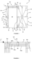
Figure 1 is a front view of a racking resistant timber frame module including a plated beam according to an embodiment of the present invention; -
Figure 2 is a partial front view of the racking resistant timber frame module and plated beam ofFigure 1 ; -
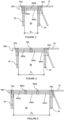
Figure 3 is a partial front view of a timber frame panel including a plated beam according to an embodiment of the present invention; -
Figure 4 is a partial front view of a timber frame panel including a plated beam according to another embodiment of the present invention; -
Figure 5 is a partial front view of a timber frame panel including a plated beam according to a further embodiment of the present invention; -
Figure 6 is a partial front view of a timber frame panel including a plated beam according to an alternative embodiment of the present invention; -
Figure 7 is a partial front view of a timber frame panel including a plated beam according to another embodiment of the present invention; -
Figure 8 is a partial front view of a timber frame panel including a plated beam according to an alternative embodiment of the present invention; -
Figure 9 is a partial front view of a timber frame panel including a plated beam according to a further embodiment of the present invention; and -
Figure 10 is a partial front view of a timber frame panel including a plated beam according to another embodiment of the present invention. - Referring now to
Figure 1 , there is shown a racking resistanttimber frame module 10. Thetimber frame module 10 includes a firsttimber frame panel 12, a secondtimber frame panel 4 and a thirdtimber frame panel 16. Thetimber frame module 10 also includes atop rail 18 and abase rail 20. Thetop rail 18 and thebase rail 20 form the top rail of each of the firsttimber frame panel 12, the secondtimber frame panel 14 and the thirdtimber frame panel 16. - The
top rail 18 and thebase rail 20 are in parallel orientation relative to each other. Thetop rail 18 and thebase rail 20 are arranged to be horizontally oriented when thetimber frame module 10 is in situ in a timber framed structure. - The first
timber frame panel 12 includes afirst stud 22 and an opposingsecond stud 24. Each of thefirst stud 22 and thesecond stud 24 is connected at a first end to thetop rail 18 and at a second, opposite, end to thebase rail 20. The firsttimber frame panel 12 also includes amid rail 26, a firstdiagonal brace 28 and a seconddiagonal brace 30. Themid rail 26 extends between and is connected to each of thefirst stud 22 and thesecond stud 24. The firstdiagonal brace 28 extends between and is connected to thetop rail 18 and themid rail 26. The seconddiagonal brace 30 extends between and is connected to themid rail 26 and thebase rail 20. - The second
timber frame panel 14 includes afirst stud 32 and an opposingsecond stud 34. Each of thefirst stud 32 and thesecond stud 34 is connected at a first end to thetop rail 18 and at a second, opposite, end to thebase rail 20. Thesecond timber frame 14 also includes a plated orlaminate beam 100 as will be described in more detail below. An aperture oropening 36, for example an opening suitable for receiving a door frame, is defined between the platedbeam 100, thefirst stud 32, thesecond stud 36 and thebase rail 20. - The third
timber frame panel 16 includes afirst stud 42, asecond stud 44 and athird stud 45. Each of thefirst stud 42, thesecond stud 44 and thethird stud 45 is connected at a first end to thetop rail 18 and at a second, opposite, end to thebase rail 20. The thirdtimber frame panel 16 also includes a firstmid rail 46, and a secondmid rail 47, a firstdiagonal brace 48, a seconddiagonal brace 50, a thirddiagonal brace 49 and a fourthdiagonal brace 51. The firstmid rail 46 extends between and is connected to each of thefirst stud 42 and thesecond stud 44. The secondmid rail 47 extends between and is connected to each of thesecond stud 44 and thethird stud 45 . The firstdiagonal brace 48 extends between and is connected to thetop rail 18 and the firstmid rail 46. The seconddiagonal brace 50 extends between and is connected to the firstmid rail 46 and thebase rail 20. The thirddiagonal brace 49 extends between and is connected to thetop rail 18 and the secondmid rail 47. The fourthdiagonal brace 51 extends between and is connected to the secondmid rail 47 and thebase rail 20. - The
first timber panel 12 is connected to thesecond timber panel 14 by means of a plurality ofnail plates second timber panel 14 is positioned adjacent to thefirst timber panel 12 such that thefirst stud 32 of thesecond timber panel 14 abuts thesecond stud 24 of thefirst timber panel 12.Nail plate 52a is used to connect thefirst stud 32 of thesecond timber panel 14 and thesecond stud 24 of thefirst timber panel 12 to each other and to thetop rail 18.Nail plate 52b is used to connect thefirst stud 32 of thesecond timber panel 14 and thesecond stud 24 of thefirst timber panel 12 to each other and to themid rail 26, the firstdiagonal brace 28 and the seconddiagonal brace 30.Nail plate 52c is used to connect thefirst stud 32 of thesecond timber panel 14 and thesecond stud 24 of thefirst timber panel 12 to each other and to thebase rail 20. - Similarly, the
third timber panel 16 is connected to thesecond timber panel 14 by means of a plurality ofnail plates third timber panel 16 is positioned adjacent to thesecond timber panel 14 such that thefirst stud 42 of thethird timber panel 16 abuts thesecond stud 34 of thesecond timber panel 14.Nail plate 54a is used to connect thefirst stud 42 of thethird timber panel 16 and thesecond stud 34 of thesecond timber panel 14 to each other, as well as to thetop rail 18 and the firstdiagonal brace 48.Nail plate 54b is used to connect thefirst stud 42 of thethird timber panel 16 and thesecond stud 34 of thesecond timber panel 14 to each other and to the firstmid rail 46.Nail plate 54c is used to connect thefirst stud 42 of thethird timber panel 16 and thesecond stud 34 of thesecond timber panel 14 to each other, as well as to thebottom rail 20 and the seconddiagonal brace 50. At each location where a nail plate is provided, a nail plate is provided on either face of themodule 10. - The first and
second studs timber frame panel 12, the first andsecond studs timber frame panel 14 and the first, second andthird studs timber frame panel 16 are in parallel orientation relative to each other. Each of the first andsecond studs timber frame panel 12, the first andsecond studs timber frame panel 14 and the first, second andthird studs timber frame panel 16 are arranged to be vertically oriented when thetimber frame module 10 is in situ in a timber frame structure. In other words, the longitudinal axis of each of the first andsecond studs timber frame panel 12, the first andsecond studs timber frame panel 14 and the first, second andthird studs timber frame panel 16 are perpendicular to the longitudinal axis of each of thetop rail 18 and thebase rail 20. - The
top rail 18, thebase rail 20, thefirst stud 22 of the firsttimber frame panel 12 and thethird stud 45 of the thirdtimber frame panel 16 define a perimeter of thetimber frame module 10. More specifically,first stud 22 of the firsttimber frame panel 12 and thethird stud 45 of the thirdtimber frame panel 16 are each attached at opposing ends of each of thetop rail 18 and thebase rail 20. - Each of the
top rail 18, thebase rail 20, first andsecond studs mid rail 26 and thediagonal braces timber frame panel 12, the first andsecond studs beam 100 of the secondtimber frame panel 14 and the first, second andthird studs mid rails diagonal braces timber frame panel 16 are manufactured from timber, for example TR26 timber. The timber used for the components of themodule 10 has a width of approximately 35 mm and a depth of approximately 72 mm. In this way, the depth (or thickness) of eachmodule 10 will be approximately 72 mm. - The plated
beam 100 will now be described with particular reference toFigure 2 . - The plated
beam 100 is an adhesive-free plated beam. The adhesive-free platedbeam 100 includes a plurality ofbeam plates nail plate 162. - A
first beam plate 160a is positioned in parallel orientation relative to thetop rail 18 such that thefirst beam plate 160a abuts thetop rail 18. Asecond beam plate 160b is positioned in parallel orientation relative to thetop rail 18 and thefirst beam plate 160a such that thesecond beam plate 160b abuts thefirst beam plate 160a. Similarly, athird beam plate 160c is positioned in parallel orientation relative to thetop rail 18, thefirst beam plate 160a and thesecond beam plate 160b such that thethird beam plate 160c abuts thesecond beam plate 160b. Likewise, afourth beam plate 160d is positioned in parallel orientation relative to thetop rail 18, thefirst beam plate 160a, thesecond beam plate 160b and the third beam plated 160c such that thefourth beam plate 160d abuts thethird beam plate 160c. - The
nail plate 162 provides a connection between adjacent beam plates and thetop rail 18 in a central portion of the platedbeam 100, that is a portion of the platedbeam 100 which is spaced apart from each of thefirst stud 32 and thesecond stud 34 of thesecond timber panel 14. - The
nail plate 52a of thetimber frame module 10 provides a further connection between adjacent beam plates, thetop rail 18 and thefirst stud 32. Similarly, thenail plate 54a of thetimber frame module 10 provides a further connection between adjacent beam plates, thetop rail 18 and thesecond stud 34. - Advantageously, the invention enables the use of off cuts from the manufacture of timber frame panels as structural components of a panel, reducing the amount of timber waste produced and improving the resistance of the resulting panel to racking loads.
- The invention also enables the use of a continuous top rail for a timber frame panel or module incorporating the plated beam, which further improves the integrity of the plated beam and the resistance of the resulting panel to racking loads. In other words, the invention obviates the need to cut the top rail in order to insert a plated beam into the timber frame panel or module.
- It will be appreciated by those skilled in the art that several variations to the aforementioned embodiments are envisaged without departing from the scope of the invention. For example, in the example described above, the plated
beam 100 includes fourbeam plates - In the example described above, a single
central nail plate 162 provides a connection between adjacent beam plates and thetop rail 18 in a central portion of the platedbeam 100. The number of nail plates included within the plated beam may be varied according to the desired racking resistance of the resulting timber frame structure and/or the desired height of the opening and/or the desired length of the opening provided within the structure. As the length or span of an opening or aperture within the timber frame structure is increased, the number of nail plates within the plated beam may be increased in order to ensure that a characteristic or predetermined racking load resistance can be achieved for the timber frame structure. In some examples of the invention, the central nail plate or central nail plates may be omitted. - Examples of variations to the invention will now be described with reference to
Figures 3 to 10 . - The plated beams 200, 300, 400, 500 of
Figures 3 to 6 each include threeadjacent beam plates beams Figures 7 to 10 each include fouradjacent beam plates - The plated
beam 200 ofFigure 3 has a length or span D1. The length D1 may be approximately 600 mm. The platedbeam 300 ofFigure 4 has a length or span D2. The length D2 may be approximately 1200 mm. The platedbeam 400 ofFigure 5 has a length or span D3. The length D3 may be approximately 1800 mm. The platedbeam 500 ofFigure 6 has a length or span D4. The length D4 may be approximately 2400 mm. The platedbeam 600 ofFigure 7 has a length or span D5. The length D5 may be approximately 600 mm. The platedbeam 700 ofFigure 8 has a length or span D6. The length D6 may be approximately 1200 mm. The platedbeam 800 ofFigure 9 has a length or span D7. The length D7 may be approximately 1800 mm. The platedbeam 900 ofFigure 10 has a length or span D8. The length D8 may be approximately 2400 mm. - The plated
beam 200 ofFigure 3 does not include a central nail plate. Eachbeam plate beam 200 is connected to an adjacent beam plate and/or to thetop rail 18 by means ofnail plates beam 200. Thenail plates beam 200 to theend studs - The plated
beam 300 ofFigure 4 includes a singlecentral nail plate 362 in addition tonail plates beam 300. Eachbeam plate beam 300 is connected to an adjacent beam plate and/or to thetop rail 18 by means ofnail plates central nail plate 362 is spaced apart from thenail plate 52a by a distance of approximately 600mm. Thecentral nail plate 362 is spaced apart from thenail plate 54a by a distance of approximately 600 mm. - The plated
beam 400 ofFigure 5 includes twocentral nail plates nail plates beam 400. Eachbeam plate beam 400 is connected to an adjacent beam plate and/or to thetop rail 18 by means ofnail plates nail plate 462a is spaced apart from each of thenail plate 52a and thenail plate 462b by a distance of approximately 600mm. Thenail plate 462b is spaced apart from thenail plate 54a by a distance of approximately 600 mm. - The plated
beam 500 ofFigure 6 includes threecentral nail plates nail plates beam 500. Eachbeam plate beam 500 is connected to an adjacent beam plate and/or to thetop rail 18 by means ofnail plates nail plate 562a is spaced apart from each of thenail plate 52a and thenail plate 562b by a distance of approximately 600mm. Thenail plate 562b is spaced apart from thenail plate 562c by a distance of approximately 600 mm. Thenail plate 562c is spaced apart from thenail plate 54a by a distance of approximately 600 mm. - The plated
beam 600 ofFigure 7 does not include a central nail plate. Eachbeam plate beam 600 is connected to an adjacent beam plate and/or to thetop rail 18 by means ofnail plates beam 600. Thenail plates beam 600 to theend studs - The plated
beam 700 ofFigure 8 includes a singlecentral nail plate 762 in addition tonail plates beam 700. Eachbeam plate beam 700 is connected to an adjacent beam plate and/or to thetop rail 18 by means ofnail plates central nail plate 762 is spaced apart from thenail plate 52a by a distance of approximately 600mm. Thecentral nail plate 762 is spaced apart from thenail plate 54a by a distance of approximately 600 mm. - The plated
beam 800 ofFigure 9 includes twocentral nail plates nail plates beam 800. Eachbeam plate beam 800 is connected to an adjacent beam plate and/or to thetop rail 18 by means ofnail plates nail plate 862a is spaced apart from each of thenail plate 52a and thenail plate 862b by a distance of approximately 600mm. Thenail plate 862b is spaced apart from thenail plate 54a by a distance of approximately 600 mm. - The plated
beam 900 ofFigure 10 includes threecentral nail plates nail plates beam 900. Eachbeam plate beam 900 is connected to an adjacent beam plate and/or to thetop rail 18 by means ofnail plates nail plate 962a is spaced apart from each of thenail plate 52a and thenail plate 962b by a distance of approximately 600mm. Thenail plate 962b is spaced apart from thenail plate 962c by a distance of approximately 600 mm. Thenail plate 962c is spaced apart from thenail plate 54a by a distance of approximately 600 mm. - It will also be appreciated by those skilled in the art that any number of combinations of the aforementioned features and/or those shown in the appended drawings provide clear advantages over the prior art and are therefore within the scope of the invention described herein.
Claims (12)
- An adhesive-free plated beam for a timber-frame panel, the adhesive-free plated beam comprising a top rail and at least one beam plate in parallel orientation relative to one another, wherein the at least one beam plate abuts the top rail and is connected to the top rail by means of a nail plate.
- An adhesive-free plated beam according to claim 1, wherein the at least one beam plate comprises a first beam plate and a second beam plate.
- An adhesive-free plated beam according to claim 1 or claim 2, wherein the nail plate is a first nail plate, the plated beam further comprising a second nail plate, wherein the first nail plate connects a first end of the at least one beam plate to the top rail and the second nail plate connects a second, opposite, end of the at least one nail plate to the top rail.
- An adhesive-free plated beam according to claim 3, the adhesive-free plated beam including at least one additional nail plate.
- An adhesive-free plated beam according to claim 4, wherein the at least one additional nail plate is spaced apart from the first nail plate and/or the second nail plate.
- An adhesive-free plated beam according to any of claims 1 to 5, wherein the at least one beam plate has a width, for example wherein the width is 35 mm.
- An adhesive-free plated beam according to any of claims 1 to 6, wherein the at least beam plate has a depth, for example wherein the depth is 72 mm.
- A timber-frame panel comprising:a top rail,a first stud, anda second, opposing, stud,wherein each of the first stud and the second stud are connected to the top rail and are spaced apart by a distance,
the timber-frame panel further comprising:
at least one beam plate, wherein the at least one beam plate extends in parallel orientation relative to the top rail, abuts the top rail and is connected to the top rail by means of a nail plate. - A timber-frame panel according to claim 8, wherein the at least one beam plate has a length which corresponds to the distance between the first stud and the second stud.
- A timber-frame panel according to claim 8 or claim 9, wherein the nail plate is a first nail plate and a first end of the at least one beam plate is connected to the top rail and the first stud by the first nail plate, and a second, opposite, end of the at least one beam plate is connected to the top rail and the second stud by a second nail plate.
- A timber-frame panel according to claim 10, wherein the timber-frame panel includes at least one additional nail plate.
- An adhesive-free plated beam according to claim 11, wherein the at least one additional nail plate is spaced apart from the first nail plate and/or the second nail plate.
Applications Claiming Priority (1)
| Application Number | Priority Date | Filing Date | Title |
|---|---|---|---|
| GB202118820 | 2021-12-22 |
Publications (1)
| Publication Number | Publication Date |
|---|---|
| EP4202143A1 true EP4202143A1 (en) | 2023-06-28 |
Family
ID=84980884
Family Applications (1)
| Application Number | Title | Priority Date | Filing Date |
|---|---|---|---|
| EP22215972.5A Withdrawn EP4202143A1 (en) | 2021-12-22 | 2022-12-22 | A plated beam |
Country Status (1)
| Country | Link |
|---|---|
| EP (1) | EP4202143A1 (en) |
Citations (3)
| Publication number | Priority date | Publication date | Assignee | Title |
|---|---|---|---|---|
| US5867963A (en) * | 1997-09-23 | 1999-02-09 | Truswal Systems Corporation | Trimmable truss apparatus |
| US6185898B1 (en) * | 1998-07-10 | 2001-02-13 | Robert F. Pratt | High strength wall frames and system utilizing same |
| WO2005035893A1 (en) * | 2003-10-07 | 2005-04-21 | Trussed, Inc. | Load-resisting truss segments for buildings |
-
2022
- 2022-12-22 EP EP22215972.5A patent/EP4202143A1/en not_active Withdrawn
Patent Citations (3)
| Publication number | Priority date | Publication date | Assignee | Title |
|---|---|---|---|---|
| US5867963A (en) * | 1997-09-23 | 1999-02-09 | Truswal Systems Corporation | Trimmable truss apparatus |
| US6185898B1 (en) * | 1998-07-10 | 2001-02-13 | Robert F. Pratt | High strength wall frames and system utilizing same |
| WO2005035893A1 (en) * | 2003-10-07 | 2005-04-21 | Trussed, Inc. | Load-resisting truss segments for buildings |
Similar Documents
| Publication | Publication Date | Title |
|---|---|---|
| US9194118B2 (en) | Brick bracket for installation of a ledger on the brick facing or veneer of a structure and associated methods for the installation of the brick bracket on the brick facing | |
| US10024057B2 (en) | Construction panel system and methods of assembly thereof | |
| US20220213684A1 (en) | Modular composite action panel and structural systems using same | |
| US9328506B2 (en) | Construction panel system and methods of assembly | |
| US8621803B2 (en) | Structural interlocking wood panel | |
| US20140245693A1 (en) | Method for preparing a composite membrane/wood floor diaphragm | |
| US20100088986A1 (en) | Method of constructing a building, such building, and wall and floor elements for use therein | |
| EP1757417A1 (en) | Method of manufacturing a timber frame structural panel assembly, and timber frame structural panel assembly | |
| US20060179757A1 (en) | Panel and a system of panels having improved dimensions | |
| EP1536077B1 (en) | Method of constructing a building, such building, and wall element for use therein | |
| EP3529444B1 (en) | Burglary resistant room partitioning structure and method associated therewith | |
| US6256951B1 (en) | Lateral bracing system | |
| EP4202138A1 (en) | A timber frame panel | |
| JP4334742B2 (en) | Method for manufacturing wooden beams and building members such as wooden beams and columns | |
| EP1953300B1 (en) | Arrangement for joining wood-based construction elements | |
| JP2021017802A (en) | Bearing wall | |
| JP7628429B2 (en) | Earthquake-resistant reinforcement structure | |
| JP2026502676A (en) | Wood-concrete composite connectors and ductile reinforcement supports | |
| GB2300204A (en) | A timber-frame panel | |
| JP2024036886A (en) | wooden shear wall | |
| WO2023182919A1 (en) | A building stud and a framework structure | |
| JP2025067447A (en) | Composite floor | |
| JP2026061076A (en) | Composite material | |
| WO2025027930A1 (en) | Building wall and method for constructing same | |
| JP2000204692A (en) | Plate-shaped heat insulating member used in building and heat insulating method using the same |
Legal Events
| Date | Code | Title | Description |
|---|---|---|---|
| PUAI | Public reference made under article 153(3) epc to a published international application that has entered the european phase |
Free format text: ORIGINAL CODE: 0009012 |
|
| STAA | Information on the status of an ep patent application or granted ep patent |
Free format text: STATUS: THE APPLICATION HAS BEEN PUBLISHED |
|
| AK | Designated contracting states |
Kind code of ref document: A1 Designated state(s): AL AT BE BG CH CY CZ DE DK EE ES FI FR GB GR HR HU IE IS IT LI LT LU LV MC ME MK MT NL NO PL PT RO RS SE SI SK SM TR |
|
| STAA | Information on the status of an ep patent application or granted ep patent |
Free format text: STATUS: REQUEST FOR EXAMINATION WAS MADE |
|
| 17P | Request for examination filed |
Effective date: 20231221 |
|
| RBV | Designated contracting states (corrected) |
Designated state(s): AL AT BE BG CH CY CZ DE DK EE ES FI FR GB GR HR HU IE IS IT LI LT LU LV MC ME MK MT NL NO PL PT RO RS SE SI SK SM TR |
|
| GRAP | Despatch of communication of intention to grant a patent |
Free format text: ORIGINAL CODE: EPIDOSNIGR1 |
|
| STAA | Information on the status of an ep patent application or granted ep patent |
Free format text: STATUS: GRANT OF PATENT IS INTENDED |
|
| RIC1 | Information provided on ipc code assigned before grant |
Ipc: E04C 3/16 20060101AFI20250724BHEP Ipc: E04B 1/10 20060101ALI20250724BHEP Ipc: E04B 1/26 20060101ALN20250724BHEP |
|
| INTG | Intention to grant announced |
Effective date: 20250801 |
|
| STAA | Information on the status of an ep patent application or granted ep patent |
Free format text: STATUS: THE APPLICATION IS DEEMED TO BE WITHDRAWN |
|
| 18D | Application deemed to be withdrawn |
Effective date: 20251202 |