EP4202107A1 - Inner drum assembly and laundry treatment apparatus - Google Patents
Inner drum assembly and laundry treatment apparatus Download PDFInfo
- Publication number
- EP4202107A1 EP4202107A1 EP20951056.9A EP20951056A EP4202107A1 EP 4202107 A1 EP4202107 A1 EP 4202107A1 EP 20951056 A EP20951056 A EP 20951056A EP 4202107 A1 EP4202107 A1 EP 4202107A1
- Authority
- EP
- European Patent Office
- Prior art keywords
- water inlet
- water
- inner tub
- hole
- sub
- Prior art date
- Legal status (The legal status is an assumption and is not a legal conclusion. Google has not performed a legal analysis and makes no representation as to the accuracy of the status listed.)
- Pending
Links
Images


Classifications
-
- D—TEXTILES; PAPER
- D06—TREATMENT OF TEXTILES OR THE LIKE; LAUNDERING; FLEXIBLE MATERIALS NOT OTHERWISE PROVIDED FOR
- D06F—LAUNDERING, DRYING, IRONING, PRESSING OR FOLDING TEXTILE ARTICLES
- D06F37/00—Details specific to washing machines covered by groups D06F21/00 - D06F25/00
- D06F37/02—Rotary receptacles, e.g. drums
- D06F37/04—Rotary receptacles, e.g. drums adapted for rotation or oscillation about a horizontal or inclined axis
-
- D—TEXTILES; PAPER
- D06—TREATMENT OF TEXTILES OR THE LIKE; LAUNDERING; FLEXIBLE MATERIALS NOT OTHERWISE PROVIDED FOR
- D06F—LAUNDERING, DRYING, IRONING, PRESSING OR FOLDING TEXTILE ARTICLES
- D06F37/00—Details specific to washing machines covered by groups D06F21/00 - D06F25/00
- D06F37/30—Driving arrangements
-
- D—TEXTILES; PAPER
- D06—TREATMENT OF TEXTILES OR THE LIKE; LAUNDERING; FLEXIBLE MATERIALS NOT OTHERWISE PROVIDED FOR
- D06F—LAUNDERING, DRYING, IRONING, PRESSING OR FOLDING TEXTILE ARTICLES
- D06F39/00—Details of washing machines not specific to a single type of machines covered by groups D06F9/00 - D06F27/00
- D06F39/08—Liquid supply or discharge arrangements
-
- D—TEXTILES; PAPER
- D06—TREATMENT OF TEXTILES OR THE LIKE; LAUNDERING; FLEXIBLE MATERIALS NOT OTHERWISE PROVIDED FOR
- D06F—LAUNDERING, DRYING, IRONING, PRESSING OR FOLDING TEXTILE ARTICLES
- D06F39/00—Details of washing machines not specific to a single type of machines covered by groups D06F9/00 - D06F27/00
- D06F39/08—Liquid supply or discharge arrangements
- D06F39/088—Liquid supply arrangements
-
- D—TEXTILES; PAPER
- D06—TREATMENT OF TEXTILES OR THE LIKE; LAUNDERING; FLEXIBLE MATERIALS NOT OTHERWISE PROVIDED FOR
- D06F—LAUNDERING, DRYING, IRONING, PRESSING OR FOLDING TEXTILE ARTICLES
- D06F23/00—Washing machines with receptacles, e.g. perforated, having a rotary movement, e.g. oscillatory movement, the receptacle serving both for washing and for centrifugally separating water from the laundry
- D06F23/02—Washing machines with receptacles, e.g. perforated, having a rotary movement, e.g. oscillatory movement, the receptacle serving both for washing and for centrifugally separating water from the laundry and rotating or oscillating about a horizontal axis
- D06F23/025—Washing machines with receptacles, e.g. perforated, having a rotary movement, e.g. oscillatory movement, the receptacle serving both for washing and for centrifugally separating water from the laundry and rotating or oscillating about a horizontal axis with a rotatable imperforate tub
-
- D—TEXTILES; PAPER
- D06—TREATMENT OF TEXTILES OR THE LIKE; LAUNDERING; FLEXIBLE MATERIALS NOT OTHERWISE PROVIDED FOR
- D06F—LAUNDERING, DRYING, IRONING, PRESSING OR FOLDING TEXTILE ARTICLES
- D06F37/00—Details specific to washing machines covered by groups D06F21/00 - D06F25/00
- D06F37/02—Rotary receptacles, e.g. drums
- D06F37/04—Rotary receptacles, e.g. drums adapted for rotation or oscillation about a horizontal or inclined axis
- D06F37/06—Ribs, lifters, or rubbing means forming part of the receptacle
-
- D—TEXTILES; PAPER
- D06—TREATMENT OF TEXTILES OR THE LIKE; LAUNDERING; FLEXIBLE MATERIALS NOT OTHERWISE PROVIDED FOR
- D06F—LAUNDERING, DRYING, IRONING, PRESSING OR FOLDING TEXTILE ARTICLES
- D06F37/00—Details specific to washing machines covered by groups D06F21/00 - D06F25/00
- D06F37/26—Casings; Tubs
- D06F37/267—Tubs specially adapted for mounting thereto components or devices not provided for in preceding subgroups
- D06F37/269—Tubs specially adapted for mounting thereto components or devices not provided for in preceding subgroups for the bearing of the rotary receptacle
Definitions
- the application relates to the technical field of laundry cleaning, and in particular to an inner tub assembly and a laundry treatment device.
- an inner tub and an outer tub are communicated with each other, the inner tub is used to hold clothes, the outer tub is used to hold water, a large number of water passing holes are arranged in the inner tub, so that the inner tub and the outer tub are communicated through the water passing holes, water in the outer tub enters the inner tub, injection and drainage of water is implemented through the outer tub.
- dirt is easily accumulated between the inner tub and the outer tub, which breeds bacteria and is not easily cleaned.
- a washing machine with a single tub used for washing is present in the related art, which is different from existing washing modes in that the inner tub is a non-porous inner tub and is isolated from the outer tub, and the single tub is not only used to hold clothes and beat or stir the clothes, but also used to hold water.
- water inflow of the washing machine with a single tub used for washing becomes a difficult technology urgently to be overcome.
- a rotation shaft 300' driving an inner tub 110' to rotate is configured as a hollow shaft which is hermetically connected to a water inlet pipe 400' by an oil seal 150' and a bearing 160', and a water flow flowing out of the water inlet pipe 400' enters a washing cavity 110a' of the inner tub 110' through an inner cavity 300a' of the hollow shaft.
- this water inflow mode may cause greases on the oil seal 150' to enter the washing cavity 110a' along with the water flow, contaminating a water source.
- an aspect of the embodiments of the application provides an inner tub assembly, including an inner tub and a water inlet disc.
- the inner tub is provided with a washing cavity, an axial end of the inner tub is provided with an opening in communication with the washing cavity, the other axial end of the inner tub is a closed end provided with a shaft mounting hole.
- the water inlet disc is connected to the closed end, provided with a water storage cavity, a water outlet and an annular water inlet surrounding the shaft mounting hole, and arranged around the shaft mounting hole, the annular water inlet is arranged on a side of the water inlet disc away from the closed end to receive an inlet water flow, and the water outlet guides water in the water storage cavity into the washing cavity.
- a plane perpendicular to an axis of the inner tub may be a projection plane, and a projection of the water outlet on the projection plane is positioned outside a projection of the annular water inlet on the projection plane.
- the inner tub assembly may further comprise a lifting rib arranged in the inner tub and provided with an accommodating cavity in communication with the washing cavity, and water flow from the water outlet entering the washing cavity through the accommodating cavity.
- the water inlet disc may comprise a disc body and a connector, and the closed end of the inner tub further includes a first through hole.
- the water storage cavity and the annular water inlet are arranged on the disc body, the annular water inlet is arranged on a side of the disc body, the connector is arranged on a side of the disc body away from the annular water inlet, an end of the connector is communicated with the water storage cavity, and the water outlet is arranged at the other end of the connector.
- the disc body is arranged around the shaft mounting hole, and the connector is hermetically arranged in the first through hole and passes through the first through hole.
- the disc body may comprise an annular convex rib, a first side plate provided with a first through hole, and a second side plate provided with a second through hole and positioned on a side of the first side plate away from the washing cavity, the first through hole and the second through hole are coaxially arranged, and a diameter of the first through hole is smaller than that of the second through hole.
- An edge of the first side plate is connected to an edge of the second side plate in a closed manner, to enclose together to form the water storage cavity.
- the annular convex rib is protruded from a side of the first side plate facing toward the second side plate, arranged around the first through hole and spaced apart from an inner wall corresponding to the second through hole, and the annular convex rib, the first side plate and the second side plate together form the annular water inlet at a position close to the first through hole.
- the connector is connected to the first side plate.
- a side of the disc body away from the connector may be partially recessed inward to form the annular water inlet.
- a side wall corresponding to the annular water inlet is provided with a first water passage port in communication with the water storage cavity, and an inlet water flow in the annular water inlet enters the water storage cavity through the first water passage port.
- the connector may comprise a first sub-segment and a second sub-segment connected along a length direction of the connector, and the inner tub assembly may further comprise a sealing ring.
- An end of the first sub-segment is connected to the disc body, a step surface facing away from the disc body is formed at an interface between the first sub-segment and the second sub-segment, and an end of the second sub-segment away from the first sub-segment passes through the first through hole and extends into the inner tub.
- the sealing ring is sleeved on the second sub-segment, and sandwiched between the step surface and the closed end of the inner tub.
- Another aspect of the embodiments of the application further provides a laundry treatment device, including an outer tub, a rotation shaft, a driving mechanism, a water inlet pipe, and the above inner tub assembly.
- the inner tub assembly is rotatably arranged in the outer tub.
- the rotation shaft is rotatably supported on the outer tub and in driving-connection with the driving mechanism, an end of the rotation shaft extends into the shaft mounting hole to drive the inner tub assembly to rotate under drive of the driving mechanism.
- the water inlet pipe is connected to the outer tub and supplies water to the annular water inlet.
- the water inlet pipe may comprise a pipe body and a nozzle connected to an end of the pipe body.
- a structure of the nozzle at least partially extends into the annular water inlet.
- the pipe body may comprise a first sub-pipe and a second sub-pipe connected to each other, and an end of the outer tub close to the water inlet disc is provided with a second through hole eccentrically arranged relative to the rotation shaft.
- the first sub-pipe is arranged in the second through hole and passes through the second through hole, an end of the first sub-pipe extends into the outer tub and is connected to the nozzle, and the other end of the first sub-pipe is positioned outside the outer tub.
- the second sub-pipe is positioned outside the outer tub and extends along a lateral side of the first sub-pipe.
- the water inlet disc provided with the water storage cavity, the water outlet and the annular water inlet is arranged at the closed end of the inner tub, the inlet water flow may be directly injected into the annular water inlet through the water inlet pipe during rotation of the inner tub, and water flowing into the water storage cavity is guided into the washing cavity through the water outlet, without configuring the rotation shaft as a hollow shaft, even without injecting the inlet water flow into the washing cavity through an inner cavity of the hollow shaft. Therefore, greases on an oil seal and other parts may also be prevented from being brought into the washing cavity of the inner tub and contaminating the water source, while water inflow is facilitated.
- the inner tub assembly 100 includes an inner tub 110 and a water inlet disc 120.
- the inner tub 110 is provided with a washing cavity 110a, an axial end of the inner tub 110 is provided with an opening 110b in communication with the washing cavity 110a, the other axial end of the inner tub 110 is a closed end 110c provided with a shaft mounting hole 110d, and the shaft mounting hole 110d is configured to mount a rotation shaft 300 driving the inner tub 110 to rotate.
- the water inlet disc 120 is provided with a water storage cavity 120a, a water outlet 120b and an annular water inlet 120c surrounding the shaft mounting hole 110d, is connected to the closed end 110c and arranged around the shaft mounting hole 110d.
- the water inlet disc 120 is fixed on the inner tub 110, and when the rotation shaft 300 is mounted in the shaft mounting hole 110d, the water inlet disc 120 and the annular water inlet 120c surround a circumferential side of the rotation shaft 300.
- the annular water inlet 120c is arranged on a side of the water inlet disc 120 away from the closed end 110c to receive an inlet water flow, and the water outlet 120b guides water in the water storage cavity 120a into the washing cavity 110a. That is, the inlet water flow flows into the water storage cavity 120a through the annular water inlet 120c, and water in the water storage cavity 120a flows into the washing cavity 110a through the water outlet 120b.
- the laundry treatment device may be a washing machine or an integrated washing and drying machine.
- the laundry treatment device is a drum washing machine, and an axis of the inner tub 110 substantially extends in a horizontal direction, that is, the axis of the inner tub 110 may be horizontally arranged, or may have a certain inclination angle.
- the inner tub 110 of the embodiment of the application may hold water, that is, washing water is held in the inner tub 11 in a process of the laundry treatment device washing laundries, and the inner tub 11 may also be referred to as a non-porous inner tub 11, which may avoid the problem of accumulating dirt easily due to water held in an outer tub 12 of the related art.
- the inlet water flow flows out from a water inlet pipe 400 connected to an outer tub 200 of the laundry treatment device, and when the inner tub 110 rotates, only the water inlet disc 120 rotates along with the inner tub 110, and the water inlet pipe 400 does not rotate along with the inner tub 110.
- the annular water inlet 120c is arranged on the water inlet disc 120, the water inlet pipe 400 facing toward the annular water inlet 120c may always remain in communication with the annular water inlet 120c during rotation of the inner tub 110, and continuously inject the inlet water flow into the annular water inlet 120c.
- injection of water is implemented by the water inlet pipe 400 directly injecting the inlet water flow into the annular water inlet 120c, therefore, it is unnecessary to configure the rotation shaft 300 as a hollow shaft, even unnecessary to inject the inlet water flow into the washing cavity 110a through an inner cavity of the hollow shaft. It may be seen that with usage of the inner tub assembly 100 of the embodiment of the application, greases on an oil seal and other parts may be prevented from being brought into the washing cavity 110a and contaminating the water source during water inflow.
- the oil seal 150' arranged on the rotation shaft 300' increases resistance of the rotation shaft 300', and thus affects washing and dewatering efficiencies of the laundry treatment device.
- the rotation shaft 300 of the embodiment of the application is not connected to the water inlet pipe 400, it is unnecessary to arrange a sealing structure such as an oil seal or the like on the rotation shaft 300, so that rotation resistance of the rotation shaft 300 may be prevented from being increased due to arrangement of the sealing structure such as the oil seal or the like, and thus washing and dewatering efficiencies of the laundry treatment device may be improved.
- a plane perpendicular to an axis of the inner tub 110 is a projection plane, and a projection of the water outlet 120b on the projection plane is positioned outside a projection of the annular water inlet 120c on the projection plane. That is, a distance between the water outlet 120b and the axis of the inner tub 110 is greater than a distance between the annular water inlet 120c and the axis of the inner tub 110.
- the axis of the inner tub 110 of the embodiment of the application substantially extends in the horizontal direction
- the inlet water flow naturally flows to a lower portion of the water storage cavity 120a under an action of gravity, and flows into the washing cavity 110a through the water outlet 120b at the lower portion of the water storage cavity 120a.
- the water inlet pipe 400 injects water into the annular water inlet 120c during rotation of the inner tub 110, the inlet water flow flows outward to the water outlet 120b along a radial direction of the inner tub 110 under an action of centrifugal force and gravity.
- the water outlet 120b is arranged at a position relatively far from the axis of the inner tub 110, so that water in the water storage cavity 120a may be conveniently guided into the washing cavity 110a.
- the inner tub assembly 100 further includes a lifting rib 130 arranged in the inner tub 110 and provided with an accommodating cavity 130a in communication with the washing cavity 110a, and water flow from the water outlet 120b enters the washing cavity 110a through the accommodating cavity 130a. That is, the water outlet 120b of the water inlet disc 120 may be hidden in the lifting rib 130, to prevent laundries in the washing cavity 110a from blocking the water outlet 120b, and also prevent the water outlet 120b from scratching laundries in the washing cavity 110a.
- an edge of the lifting rib 130 is provided with a plurality of second water passage ports 130b, and after water from the water outlet 120b enters the accommodating cavity 130a, water enters the washing cavity 110a through the plurality of second water passage ports 130b.
- water outlet 120b may also be directly communicated with the washing cavity 110a, that is, water from the water outlet 120b may directly enter the washing cavity 110a without entering the washing cavity 110a through the accommodating cavity 130a.
- the water inlet disc 120 includes a disc body 121 and a connector 122, and the closed end 110c of the inner tub 110 further includes a first through hole (not shown in the figure).
- the water storage cavity 120a and the annular water inlet 120c are arranged on the disc body 121, the annular water inlet 120c is arranged on a side of the disc body 121, the connector 122 is arranged on a side of the disc body 121 away from the annular water inlet 120c, an end of the connector 122 is communicated with the water storage cavity 120a, and the water outlet 120b is arranged at the other end of the connector 122.
- the disc body 121 is arranged around the shaft mounting hole 110d, and the connector 122 is hermetically arranged in the first through hole and passes through the first through hole.
- the disc body 121 is provided to facilitate receiving and holding the inlet water flow, and the connector 122 is provided to facilitate connection between the water inlet disc 120 and the closed end 110c of the inner tub 110.
- the disc body 121 includes an annular convex rib 1211, a first side plate 1212 provided with a first through hole 1212a, and a second side plate 1213 provided with a second through hole 1213a and positioned on a side of the first side plate 1212 away from the washing cavity 110a, the first through hole 1212a and the second through hole 1213a are coaxially arranged, and a diameter of the first through hole 1212a is smaller than that of the second through hole 1213a.
- An edge of the first side plate 1211 is connected to an edge of the second side plate 1213 in a closed manner, to enclose together to form the water storage cavity 120a.
- the annular convex rib 1211 is protruded from a side of the first side plate 1212 facing toward the second side plate 1213, arranged around the first through hole 1212a and spaced apart from an inner wall corresponding to the second through hole 1213a, and the annular convex rib 1211, the first side plate 1212 and the second side plate 1213 together form the annular water inlet 120c at a position close to the first through hole 1212a.
- the connector 122 is connected to the first side plate 1212.
- the water inlet disc 120 is positioned between the inner tub 110 and the outer tub 200. Therefore, the water storage cavity 120a and the annular water inlet 120c are configured by the annular convex rib 1211, the first side plate 1212 provided with the first through hole 1212a, and the second side plate 1213 provided with the second through hole 1213a, so that the whole structure of the disc body 121 may be small, extraordinar and compact, and thus the water inlet disc 120 may be accommodated by fully utilizing a free space between the inner tub 110 and the outer tub 200 without occupying too much internal space of the outer tub 200, thereby preventing an effective volume of the inner tub 110 from being reduced to a certain extent due to arrangement of the water inlet disc 120.
- shape of the disc body 121 may be appropriately adjusted according to shapes of the outer tub 200 and other components mounted on the outer tub 200.
- a middle region of the disc body 121 may be recessed in a direction in which the inner tub 110 is positioned, to form an avoidance space for avoiding the outer tub 200 and other components mounted on the outer tub 200, thereby further reducing space occupied by the water inlet disc 120.
- Communication modes of the annular water inlet 120c on the disc body 121 and the water storage cavity 120a are not limited, as long as the inlet water flow entering the annular water inlet 120c may flow into the water storage cavity 120a.
- a side of the annular water inlet 120c close to the water storage cavity 120a is opened, that is, there is no side wall arranged on the side of the annular water inlet 120c close to the water storage cavity 120a, and the inlet water flow entering the annular water inlet 120c may directly flow into the water storage cavity 120a, thereby improving efficiency of the inlet water flow flowing into the water storage cavity 120a.
- a side of the disc body 121 away from the connector 122 is partially recessed inward to form the annular water inlet 120c.
- a side wall 120d corresponding to the annular water inlet 120c is provided with a first water passage port 120e in communication with the water storage cavity 120a, and an inlet water flow in the annular water inlet 120c enters the water storage cavity 120a through the first water passage port 120e. That is, the side of the annular water inlet 120c close to the water storage cavity 120a is provided with the side wall 120d, and the side wall 120d is provided with the first water passage port 120e, and the number of the first water passage port 120e is not limited.
- the inlet water flow entering the annular water inlet 120c needs to flow into the water storage cavity 120a through the first water passage port 120e.
- the side wall 120d may be provided to support the first side plate 1212 and the second side plate 1213, so as to prevent deformation of the first side plate 1212 and the second side plate 1213.
- the number of the connector 122 is not limited, there may be one or more connectors.
- there are a plurality of connectors 122 and a plurality of first through holes the plurality of connectors 122 are arranged at intervals on the same side of the disc body 121, and each of the connectors 122 is hermetically arranged in a corresponding one of the first through holes and passes through the corresponding one of the first through holes.
- the plurality of connectors 122 are provided to facilitate fixing the water inlet disc 120 firmly to the closed end 110c of the inner tub 110, and improve water inflow efficiency.
- an end of the connector 122 provided with the water outlet 120b may extend into the washing cavity 110a, and in some other embodiments, this end may also extend into the accommodating cavity 130a, and the connector 122 is provided to facilitate connection between the water inlet disc 120 and the closed end 110c of the inner tub 110.
- the connector 122 includes a first sub-segment 122a and a second sub-segment 122b connected along a length direction of the connector 122, and the inner tub assembly 100 further includes a sealing ring 140.
- An end of the first sub-segment 122a is connected to the disc body 121, a step surface 122c facing away from the disc body 121 is formed at an interface between the first sub-segment 122a and the second sub-segment 122b, and an end of the second sub-segment 122b away from the first sub-segment 122a passes through the first through hole and extends into the inner tub 110.
- the sealing ring 140 is sleeved on the second sub-segment 122b, and sandwiched between the step surface 122c and the closed end 110c of the inner tub 110.
- the sealing ring 140 is arranged outside the closed end 110c of the inner tub 110, and clamped by cooperation of the step surface 122c and the closed end 110c of the inner tub 110, thereby facilitating hermetical connection between the connector 122 and the first through hole.
- the laundry treatment device includes an outer tub 200, a rotation shaft 300, a driving mechanism (not shown in the figure), a water inlet pipe 400, and the above inner tub assembly 100.
- the inner tub assembly 100 is rotatably arranged in the outer tub 200.
- the rotation shaft 300 is rotatably supported on the outer tub 200 and in driving-connection with the driving mechanism, an end of the rotation shaft 300 extends into the shaft mounting hole 110d to drive the inner tub assembly 100 to rotate under drive of the driving mechanism.
- the water inlet pipe 400 is connected to the outer tub 200 and supplies water to the annular water inlet 120c. That is, the water inlet pipe 400 is fixed on the outer tub 200, rather than being connected to the inner tub 110, and the water inlet pipe 400 does not rotate along with the inner tub 110 during rotation of the inner tub 110.
- the water inlet pipe 400 includes a pipe body 410 and a nozzle 420 connected to an end of the pipe body 410.
- a structure of the nozzle 420 at least partially extends into the annular water inlet 120c.
- the nozzle 420 may spray the inlet water flow to the annular water inlet 120c, so that water supply efficiency of the water inlet pipe 400 may be improved, and the inlet water flow may also be conveniently received by the annular water inlet 120c.
- the pipe body 410 includes a first sub-pipe 411 and a second sub-pipe 412 connected to each other, and an end of the outer tub 200 close to the water inlet disc 120 is provided with a second through hole (not shown in the figure) eccentrically arranged relative to the rotation shaft 300.
- the first sub-pipe 411 is arranged in the second through hole and passes through the second through hole, an end of the first sub-pipe 411 extends into the outer tub 200 and is connected to the nozzle 420, and the other end of the first sub-pipe 411 is positioned outside the outer tub 200.
- the second sub-pipe 412 is positioned outside the outer tub 200 and extends along a lateral side of the first sub-pipe 411.
- the first sub-pipe 411 is connected to the nozzle 420 by passing through the outer tub 200 from a side of the rotation shaft 300, and the second sub-pipe 412 is arranged outside the outer tub 200 along a radial direction of the rotation shaft 300.
- the water inlet pipe 400 of the embodiment of the application may save mounting space, so that internal structures of the laundry treatment device may be more compact.
Landscapes
- Engineering & Computer Science (AREA)
- Textile Engineering (AREA)
- Detail Structures Of Washing Machines And Dryers (AREA)
Abstract
Description
- This application is filed based on and claims priority to
Chinese Patent Application No. 202010876785.4 filed on August 27, 2020 - The application relates to the technical field of laundry cleaning, and in particular to an inner tub assembly and a laundry treatment device.
- In an existing washing machine, an inner tub and an outer tub are communicated with each other, the inner tub is used to hold clothes, the outer tub is used to hold water, a large number of water passing holes are arranged in the inner tub, so that the inner tub and the outer tub are communicated through the water passing holes, water in the outer tub enters the inner tub, injection and drainage of water is implemented through the outer tub. In this type of washing machine, dirt is easily accumulated between the inner tub and the outer tub, which breeds bacteria and is not easily cleaned. To this end, a washing machine with a single tub used for washing is present in the related art, which is different from existing washing modes in that the inner tub is a non-porous inner tub and is isolated from the outer tub, and the single tub is not only used to hold clothes and beat or stir the clothes, but also used to hold water. However, water inflow of the washing machine with a single tub used for washing becomes a difficult technology urgently to be overcome.
- With reference to
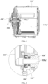
FIG. 1 and FIG. 2 , in the related art, a rotation shaft 300' driving an inner tub 110' to rotate is configured as a hollow shaft which is hermetically connected to a water inlet pipe 400' by an oil seal 150' and a bearing 160', and a water flow flowing out of the water inlet pipe 400' enters awashing cavity 110a' of the inner tub 110' through aninner cavity 300a' of the hollow shaft. - However, this water inflow mode may cause greases on the oil seal 150' to enter the
washing cavity 110a' along with the water flow, contaminating a water source. - In view of this, it is desirable for embodiments of the application to provide an inner tub assembly which facilitates water inflow and does not contaminate the water source, and a laundry treatment device.
- In order to achieve the above purpose, an aspect of the embodiments of the application provides an inner tub assembly, including an inner tub and a water inlet disc.
- The inner tub is provided with a washing cavity, an axial end of the inner tub is provided with an opening in communication with the washing cavity, the other axial end of the inner tub is a closed end provided with a shaft mounting hole.
- The water inlet disc is connected to the closed end, provided with a water storage cavity, a water outlet and an annular water inlet surrounding the shaft mounting hole, and arranged around the shaft mounting hole, the annular water inlet is arranged on a side of the water inlet disc away from the closed end to receive an inlet water flow, and the water outlet guides water in the water storage cavity into the washing cavity.
- In an implementation, a plane perpendicular to an axis of the inner tub may be a projection plane, and a projection of the water outlet on the projection plane is positioned outside a projection of the annular water inlet on the projection plane.
- In an implementation, the inner tub assembly may further comprise a lifting rib arranged in the inner tub and provided with an accommodating cavity in communication with the washing cavity, and water flow from the water outlet entering the washing cavity through the accommodating cavity.
- In an implementation, the water inlet disc may comprise a disc body and a connector, and the closed end of the inner tub further includes a first through hole.
- The water storage cavity and the annular water inlet are arranged on the disc body, the annular water inlet is arranged on a side of the disc body, the connector is arranged on a side of the disc body away from the annular water inlet, an end of the connector is communicated with the water storage cavity, and the water outlet is arranged at the other end of the connector.
- The disc body is arranged around the shaft mounting hole, and the connector is hermetically arranged in the first through hole and passes through the first through hole.
- In an implementation, the disc body may comprise an annular convex rib, a first side plate provided with a first through hole, and a second side plate provided with a second through hole and positioned on a side of the first side plate away from the washing cavity, the first through hole and the second through hole are coaxially arranged, and a diameter of the first through hole is smaller than that of the second through hole.
- An edge of the first side plate is connected to an edge of the second side plate in a closed manner, to enclose together to form the water storage cavity.
- The annular convex rib is protruded from a side of the first side plate facing toward the second side plate, arranged around the first through hole and spaced apart from an inner wall corresponding to the second through hole, and the annular convex rib, the first side plate and the second side plate together form the annular water inlet at a position close to the first through hole.
- The connector is connected to the first side plate.
- In an implementation, a side of the disc body away from the connector may be partially recessed inward to form the annular water inlet.
- A side wall corresponding to the annular water inlet is provided with a first water passage port in communication with the water storage cavity, and an inlet water flow in the annular water inlet enters the water storage cavity through the first water passage port.
- In an implementation, the connector may comprise a first sub-segment and a second sub-segment connected along a length direction of the connector, and the inner tub assembly may further comprise a sealing ring.
- An end of the first sub-segment is connected to the disc body, a step surface facing away from the disc body is formed at an interface between the first sub-segment and the second sub-segment, and an end of the second sub-segment away from the first sub-segment passes through the first through hole and extends into the inner tub.
- The sealing ring is sleeved on the second sub-segment, and sandwiched between the step surface and the closed end of the inner tub.
- In an implementation, there may be a plurality of connectors and a plurality of first through holes, the plurality of connectors are arranged at intervals on the same side of the disc body, and each of the connectors is hermetically arranged in a corresponding one of the first through holes and passes through the corresponding one of the first through holes.
- Another aspect of the embodiments of the application further provides a laundry treatment device, including an outer tub, a rotation shaft, a driving mechanism, a water inlet pipe, and the above inner tub assembly.
- The inner tub assembly is rotatably arranged in the outer tub.
- The rotation shaft is rotatably supported on the outer tub and in driving-connection with the driving mechanism, an end of the rotation shaft extends into the shaft mounting hole to drive the inner tub assembly to rotate under drive of the driving mechanism.
- The water inlet pipe is connected to the outer tub and supplies water to the annular water inlet.
- In an implementation, the water inlet pipe may comprise a pipe body and a nozzle connected to an end of the pipe body.
- A structure of the nozzle at least partially extends into the annular water inlet.
- In an implementation, the pipe body may comprise a first sub-pipe and a second sub-pipe connected to each other, and an end of the outer tub close to the water inlet disc is provided with a second through hole eccentrically arranged relative to the rotation shaft.
- The first sub-pipe is arranged in the second through hole and passes through the second through hole, an end of the first sub-pipe extends into the outer tub and is connected to the nozzle, and the other end of the first sub-pipe is positioned outside the outer tub.
- The second sub-pipe is positioned outside the outer tub and extends along a lateral side of the first sub-pipe.
- According to the inner tub assembly and the laundry treatment device provided by the embodiments of the application, the water inlet disc provided with the water storage cavity, the water outlet and the annular water inlet is arranged at the closed end of the inner tub, the inlet water flow may be directly injected into the annular water inlet through the water inlet pipe during rotation of the inner tub, and water flowing into the water storage cavity is guided into the washing cavity through the water outlet, without configuring the rotation shaft as a hollow shaft, even without injecting the inlet water flow into the washing cavity through an inner cavity of the hollow shaft. Therefore, greases on an oil seal and other parts may also be prevented from being brought into the washing cavity of the inner tub and contaminating the water source, while water inflow is facilitated.
-
-
FIG. 1 is a schematic diagram of internal structures of a laundry treatment device in the related art, with dotted arrows in the figure representing a direction of water flow. -
FIG. 2 is a partially enlarged view at A ofFIG. 1 . -
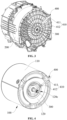
FIG. 3 is a schematic diagram of a positional relationship among an outer tub, a rotation shaft and a water inlet pipe of a laundry treatment device according to an embodiment of the application. -
FIG. 4 is a schematic structural diagram of the structure shown inFIG. 3 after the outer tub is omitted, with dotted arrows in the figure representing a direction of water flow. -
FIG. 5 is a cross-sectional view of the structure shown inFIG. 4 along an axial direction, with continuous arrows in the figure representing a direction of water flow. -
FIG. 6 is a partially enlarged view at B ofFIG. 5 . -
FIG. 7 is a partially enlarged view at C ofFIG. 5 . -
FIG. 8 is a schematic diagram of a cooperation relationship between a water inlet disc and the water inlet pipe shown inFIG. 4 , with dotted arrows in the figure representing a direction of water flow. -
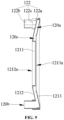
FIG. 9 is a cross-sectional view of the water inlet disc shown inFIG. 8 along an axial direction. -
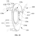
FIG. 10 is a schematic diagram of a cooperation relationship between a water inlet disc and a water inlet pipe according to another embodiment of the application, with dotted arrows in the figure representing a direction of water flow. - It should be noted that embodiments of the application and technical features in the embodiments may be combined with each other without conflict, and detailed descriptions in specific implementations should be understood as explanation and illustration of the purpose of the application, and should not be regarded as an improper limitation to the application.
- An embodiment of the application provides an
inner tub assembly 100, with reference toFIG. 4 to FIG. 9 , theinner tub assembly 100 includes aninner tub 110 and awater inlet disc 120. Theinner tub 110 is provided with awashing cavity 110a, an axial end of theinner tub 110 is provided with anopening 110b in communication with thewashing cavity 110a, the other axial end of theinner tub 110 is aclosed end 110c provided with ashaft mounting hole 110d, and theshaft mounting hole 110d is configured to mount arotation shaft 300 driving theinner tub 110 to rotate. Thewater inlet disc 120 is provided with awater storage cavity 120a, awater outlet 120b and anannular water inlet 120c surrounding theshaft mounting hole 110d, is connected to theclosed end 110c and arranged around theshaft mounting hole 110d. That is, thewater inlet disc 120 is fixed on theinner tub 110, and when therotation shaft 300 is mounted in theshaft mounting hole 110d, thewater inlet disc 120 and theannular water inlet 120c surround a circumferential side of therotation shaft 300. Theannular water inlet 120c is arranged on a side of thewater inlet disc 120 away from theclosed end 110c to receive an inlet water flow, and thewater outlet 120b guides water in thewater storage cavity 120a into thewashing cavity 110a. That is, the inlet water flow flows into thewater storage cavity 120a through theannular water inlet 120c, and water in thewater storage cavity 120a flows into thewashing cavity 110a through thewater outlet 120b. - Specifically, the laundry treatment device according to the embodiment of the application may be a washing machine or an integrated washing and drying machine. Exemplarily, the laundry treatment device is a drum washing machine, and an axis of the
inner tub 110 substantially extends in a horizontal direction, that is, the axis of theinner tub 110 may be horizontally arranged, or may have a certain inclination angle. - The
inner tub 110 of the embodiment of the application may hold water, that is, washing water is held in the inner tub 11 in a process of the laundry treatment device washing laundries, and the inner tub 11 may also be referred to as a non-porous inner tub 11, which may avoid the problem of accumulating dirt easily due to water held in an outer tub 12 of the related art. - With reference to
FIG. 3 and FIG. 4 , in the embodiment of the application, the inlet water flow flows out from awater inlet pipe 400 connected to anouter tub 200 of the laundry treatment device, and when theinner tub 110 rotates, only thewater inlet disc 120 rotates along with theinner tub 110, and thewater inlet pipe 400 does not rotate along with theinner tub 110. However, since theannular water inlet 120c is arranged on thewater inlet disc 120, thewater inlet pipe 400 facing toward theannular water inlet 120c may always remain in communication with theannular water inlet 120c during rotation of theinner tub 110, and continuously inject the inlet water flow into theannular water inlet 120c. That is, injection of water is implemented by thewater inlet pipe 400 directly injecting the inlet water flow into theannular water inlet 120c, therefore, it is unnecessary to configure therotation shaft 300 as a hollow shaft, even unnecessary to inject the inlet water flow into thewashing cavity 110a through an inner cavity of the hollow shaft. It may be seen that with usage of theinner tub assembly 100 of the embodiment of the application, greases on an oil seal and other parts may be prevented from being brought into thewashing cavity 110a and contaminating the water source during water inflow. - Furthermore, with reference to
FIG. 1 , in the related art, the oil seal 150' arranged on the rotation shaft 300' increases resistance of the rotation shaft 300', and thus affects washing and dewatering efficiencies of the laundry treatment device. However, since therotation shaft 300 of the embodiment of the application is not connected to thewater inlet pipe 400, it is unnecessary to arrange a sealing structure such as an oil seal or the like on therotation shaft 300, so that rotation resistance of therotation shaft 300 may be prevented from being increased due to arrangement of the sealing structure such as the oil seal or the like, and thus washing and dewatering efficiencies of the laundry treatment device may be improved. - In an embodiment, with reference to
FIG. 5 to FIG. 7 andFIG. 9 , a plane perpendicular to an axis of theinner tub 110 is a projection plane, and a projection of thewater outlet 120b on the projection plane is positioned outside a projection of theannular water inlet 120c on the projection plane. That is, a distance between thewater outlet 120b and the axis of theinner tub 110 is greater than a distance between theannular water inlet 120c and the axis of theinner tub 110. - Specifically, since the axis of the
inner tub 110 of the embodiment of the application substantially extends in the horizontal direction, when thewater inlet pipe 400 injects water into theannular water inlet 120c when theinner tub 110 is in a static state, the inlet water flow naturally flows to a lower portion of thewater storage cavity 120a under an action of gravity, and flows into thewashing cavity 110a through thewater outlet 120b at the lower portion of thewater storage cavity 120a. When thewater inlet pipe 400 injects water into theannular water inlet 120c during rotation of theinner tub 110, the inlet water flow flows outward to thewater outlet 120b along a radial direction of theinner tub 110 under an action of centrifugal force and gravity. Therefore, compared with an arrangement position of theannular water inlet 120c, thewater outlet 120b is arranged at a position relatively far from the axis of theinner tub 110, so that water in thewater storage cavity 120a may be conveniently guided into thewashing cavity 110a. - In an embodiment, with reference to
FIG. 5 , theinner tub assembly 100 further includes a liftingrib 130 arranged in theinner tub 110 and provided with anaccommodating cavity 130a in communication with thewashing cavity 110a, and water flow from thewater outlet 120b enters thewashing cavity 110a through theaccommodating cavity 130a. That is, thewater outlet 120b of thewater inlet disc 120 may be hidden in the liftingrib 130, to prevent laundries in thewashing cavity 110a from blocking thewater outlet 120b, and also prevent thewater outlet 120b from scratching laundries in thewashing cavity 110a. - Specific modes by which the
accommodating cavity 130a is communicated with thewashing cavity 110a are not limited. Exemplarily, with reference toFIG. 5 , an edge of the liftingrib 130 is provided with a plurality of secondwater passage ports 130b, and after water from thewater outlet 120b enters theaccommodating cavity 130a, water enters thewashing cavity 110a through the plurality of secondwater passage ports 130b. - It should be noted that the
water outlet 120b may also be directly communicated with thewashing cavity 110a, that is, water from thewater outlet 120b may directly enter thewashing cavity 110a without entering thewashing cavity 110a through theaccommodating cavity 130a. - In an embodiment, with reference to
FIG. 5 to FIG. 9 , thewater inlet disc 120 includes adisc body 121 and aconnector 122, and theclosed end 110c of theinner tub 110 further includes a first through hole (not shown in the figure). Thewater storage cavity 120a and theannular water inlet 120c are arranged on thedisc body 121, theannular water inlet 120c is arranged on a side of thedisc body 121, theconnector 122 is arranged on a side of thedisc body 121 away from theannular water inlet 120c, an end of theconnector 122 is communicated with thewater storage cavity 120a, and thewater outlet 120b is arranged at the other end of theconnector 122. Thedisc body 121 is arranged around theshaft mounting hole 110d, and theconnector 122 is hermetically arranged in the first through hole and passes through the first through hole. Thedisc body 121 is provided to facilitate receiving and holding the inlet water flow, and theconnector 122 is provided to facilitate connection between thewater inlet disc 120 and theclosed end 110c of theinner tub 110. - In an embodiment, with reference to
FIG. 8 andFIG. 9 , thedisc body 121 includes an annularconvex rib 1211, afirst side plate 1212 provided with a first throughhole 1212a, and asecond side plate 1213 provided with a second throughhole 1213a and positioned on a side of thefirst side plate 1212 away from thewashing cavity 110a, the first throughhole 1212a and the second throughhole 1213a are coaxially arranged, and a diameter of the first throughhole 1212a is smaller than that of the second throughhole 1213a. An edge of thefirst side plate 1211 is connected to an edge of thesecond side plate 1213 in a closed manner, to enclose together to form thewater storage cavity 120a. The annularconvex rib 1211 is protruded from a side of thefirst side plate 1212 facing toward thesecond side plate 1213, arranged around the first throughhole 1212a and spaced apart from an inner wall corresponding to the second throughhole 1213a, and the annularconvex rib 1211, thefirst side plate 1212 and thesecond side plate 1213 together form theannular water inlet 120c at a position close to the first throughhole 1212a. Theconnector 122 is connected to thefirst side plate 1212. - Specifically, with reference to
FIG. 5 , after theinner tub assembly 100 is mounted in theouter tub 200, thewater inlet disc 120 is positioned between theinner tub 110 and theouter tub 200. Therefore, thewater storage cavity 120a and theannular water inlet 120c are configured by the annularconvex rib 1211, thefirst side plate 1212 provided with the first throughhole 1212a, and thesecond side plate 1213 provided with the second throughhole 1213a, so that the whole structure of thedisc body 121 may be small, exquisite and compact, and thus thewater inlet disc 120 may be accommodated by fully utilizing a free space between theinner tub 110 and theouter tub 200 without occupying too much internal space of theouter tub 200, thereby preventing an effective volume of theinner tub 110 from being reduced to a certain extent due to arrangement of thewater inlet disc 120. - Furthermore, shape of the
disc body 121 may be appropriately adjusted according to shapes of theouter tub 200 and other components mounted on theouter tub 200. Exemplarily, with reference toFIG. 5 ,FIG. 8 andFIG. 9 , a middle region of thedisc body 121 may be recessed in a direction in which theinner tub 110 is positioned, to form an avoidance space for avoiding theouter tub 200 and other components mounted on theouter tub 200, thereby further reducing space occupied by thewater inlet disc 120. - Communication modes of the
annular water inlet 120c on thedisc body 121 and thewater storage cavity 120a are not limited, as long as the inlet water flow entering theannular water inlet 120c may flow into thewater storage cavity 120a. - Exemplarily, with reference to
FIG. 8 andFIG. 9 , a side of theannular water inlet 120c close to thewater storage cavity 120a is opened, that is, there is no side wall arranged on the side of theannular water inlet 120c close to thewater storage cavity 120a, and the inlet water flow entering theannular water inlet 120c may directly flow into thewater storage cavity 120a, thereby improving efficiency of the inlet water flow flowing into thewater storage cavity 120a. - Exemplarily, in another embodiment, with reference to
FIG. 10 , a side of thedisc body 121 away from theconnector 122 is partially recessed inward to form theannular water inlet 120c. Aside wall 120d corresponding to theannular water inlet 120c is provided with a firstwater passage port 120e in communication with thewater storage cavity 120a, and an inlet water flow in theannular water inlet 120c enters thewater storage cavity 120a through the firstwater passage port 120e. That is, the side of theannular water inlet 120c close to thewater storage cavity 120a is provided with theside wall 120d, and theside wall 120d is provided with the firstwater passage port 120e, and the number of the firstwater passage port 120e is not limited. The inlet water flow entering theannular water inlet 120c needs to flow into thewater storage cavity 120a through the firstwater passage port 120e. Theside wall 120d may be provided to support thefirst side plate 1212 and thesecond side plate 1213, so as to prevent deformation of thefirst side plate 1212 and thesecond side plate 1213. - The number of the
connector 122 is not limited, there may be one or more connectors. Exemplarily, with reference toFIG. 8 andFIG. 9 , there are a plurality ofconnectors 122 and a plurality of first through holes, the plurality ofconnectors 122 are arranged at intervals on the same side of thedisc body 121, and each of theconnectors 122 is hermetically arranged in a corresponding one of the first through holes and passes through the corresponding one of the first through holes. The plurality ofconnectors 122 are provided to facilitate fixing thewater inlet disc 120 firmly to theclosed end 110c of theinner tub 110, and improve water inflow efficiency. - In some embodiments, an end of the
connector 122 provided with thewater outlet 120b may extend into thewashing cavity 110a, and in some other embodiments, this end may also extend into theaccommodating cavity 130a, and theconnector 122 is provided to facilitate connection between thewater inlet disc 120 and theclosed end 110c of theinner tub 110. - Specific structures of the
connector 122 are not limited. Exemplarily, with reference toFIG. 5 andFIG. 7 toFIG. 9 , theconnector 122 includes a first sub-segment 122a and a second sub-segment 122b connected along a length direction of theconnector 122, and theinner tub assembly 100 further includes asealing ring 140. An end of the first sub-segment 122a is connected to thedisc body 121, astep surface 122c facing away from thedisc body 121 is formed at an interface between the first sub-segment 122a and thesecond sub-segment 122b, and an end of the second sub-segment 122b away from thefirst sub-segment 122a passes through the first through hole and extends into theinner tub 110. The sealingring 140 is sleeved on thesecond sub-segment 122b, and sandwiched between thestep surface 122c and theclosed end 110c of theinner tub 110. That is, the sealingring 140 is arranged outside theclosed end 110c of theinner tub 110, and clamped by cooperation of thestep surface 122c and theclosed end 110c of theinner tub 110, thereby facilitating hermetical connection between theconnector 122 and the first through hole. - An embodiment of the application further provides a laundry treatment device, with reference to
FIG. 3 to FIG. 5 , the laundry treatment device includes anouter tub 200, arotation shaft 300, a driving mechanism (not shown in the figure), awater inlet pipe 400, and the aboveinner tub assembly 100. Theinner tub assembly 100 is rotatably arranged in theouter tub 200. Therotation shaft 300 is rotatably supported on theouter tub 200 and in driving-connection with the driving mechanism, an end of therotation shaft 300 extends into theshaft mounting hole 110d to drive theinner tub assembly 100 to rotate under drive of the driving mechanism. Thewater inlet pipe 400 is connected to theouter tub 200 and supplies water to theannular water inlet 120c. That is, thewater inlet pipe 400 is fixed on theouter tub 200, rather than being connected to theinner tub 110, and thewater inlet pipe 400 does not rotate along with theinner tub 110 during rotation of theinner tub 110. - In an embodiment, with reference to
FIG. 3, FIG. 4 andFIG. 8 , thewater inlet pipe 400 includes apipe body 410 and anozzle 420 connected to an end of thepipe body 410. A structure of thenozzle 420 at least partially extends into theannular water inlet 120c. When thewater inlet pipe 400 injects water into thewater storage cavity 120a, thenozzle 420 may spray the inlet water flow to theannular water inlet 120c, so that water supply efficiency of thewater inlet pipe 400 may be improved, and the inlet water flow may also be conveniently received by theannular water inlet 120c. - In an embodiment, with reference to
FIG. 3, FIG. 4 andFIG. 8 , thepipe body 410 includes afirst sub-pipe 411 and asecond sub-pipe 412 connected to each other, and an end of theouter tub 200 close to thewater inlet disc 120 is provided with a second through hole (not shown in the figure) eccentrically arranged relative to therotation shaft 300. Thefirst sub-pipe 411 is arranged in the second through hole and passes through the second through hole, an end of thefirst sub-pipe 411 extends into theouter tub 200 and is connected to thenozzle 420, and the other end of thefirst sub-pipe 411 is positioned outside theouter tub 200. Thesecond sub-pipe 412 is positioned outside theouter tub 200 and extends along a lateral side of thefirst sub-pipe 411. That is, thefirst sub-pipe 411 is connected to thenozzle 420 by passing through theouter tub 200 from a side of therotation shaft 300, and thesecond sub-pipe 412 is arranged outside theouter tub 200 along a radial direction of therotation shaft 300. Compared with a mounting mode of connecting the water inlet pipe 400' to an end of the hollow shaft as shown inFIG. 1 , thewater inlet pipe 400 of the embodiment of the application may save mounting space, so that internal structures of the laundry treatment device may be more compact. - Various embodiments/implementations provided in the application may be combined with each other without contradiction.
- The foregoing are merely preferred embodiments of the application, and are not intended to limit the application, and various changes and variations may be made to the application for those skilled in the art. Any modification, equivalent replacement, improvement, or the like made within the spirit and principle of the application shall fall within the scope of protection of the application.
Claims (11)
- An inner tub assembly, comprising:an inner tub (110), provided with a washing cavity (110a), an axial end of the inner tub (110) provided with an opening (110b) in communication with the washing cavity (110a), the other axial end of the inner tub (110) being a closed end (110c) provided with a shaft mounting hole (110d); anda water inlet disc (120), connected to the closed end (110c), provided with a water storage cavity (120a), a water outlet (120b) and an annular water inlet (120c) surrounding the shaft mounting hole (110d), and arranged around the shaft mounting hole (110d), the annular water inlet (120c) arranged on a side of the water inlet disc (120) away from the closed end (110c) to receive an inlet water flow, and the water outlet (120b) guiding water in the water storage cavity (120a) into the washing cavity (110a).
- The inner tub assembly of claim 1, wherein a plane perpendicular to an axis of the inner tub (110) is a projection plane, and a projection of the water outlet (120b) on the projection plane is positioned outside a projection of the annular water inlet (120c) on the projection plane.
- The inner tub assembly of claim 1 or 2, further comprising a lifting rib (130) arranged in the inner tub (110) and provided with an accommodating cavity (130a) in communication with the washing cavity (110a), and water flow from the water outlet (120b) entering the washing cavity (110a) through the accommodating cavity (130a).
- The inner tub assembly of claim 1, wherein the water inlet disc (120) comprises a disc body (121) and a connector (122), and the closed end (110c) of the inner tub (110) further comprises a first through hole,the water storage cavity (120a) and the annular water inlet (120c) are arranged on the disc body (121), the annular water inlet (120c) is arranged on a side of the disc body (121), the connector (122) is arranged on a side of the disc body (121) away from the annular water inlet (120c), an end of the connector (122) is communicated with the water storage cavity (120a), and the water outlet (120b) is arranged at the other end of the connector (122),the disc body (121) is arranged around the shaft mounting hole (110d), and the connector (122) is hermetically arranged in the first through hole and passes through the first through hole.
- The inner tub assembly of claim 4, wherein the disc body (121) comprises an annular convex rib (1211), a first side plate (1212) provided with a first through hole (1212a), and a second side plate (1213) provided with a second through hole (1213a) and positioned on a side of the first side plate (1212) away from the washing cavity (110a), the first through hole (1212a) and the second through hole (1213a) are coaxially arranged, and a diameter of the first through hole (1212a) is smaller than that of the second through hole (1213a),an edge of the first side plate (1212) is connected to an edge of the second side plate (1213) in a closed manner, to enclose together to form the water storage cavity (120a),the annular convex rib (1211) is protruded from a side of the first side plate (1212) facing toward the second side plate (1213), arranged around the first through hole (1212a) and spaced apart from an inner wall corresponding to the second through hole (1213a), and the annular convex rib (1211), the first side plate (1212) and the second side plate (1213) together form the annular water inlet (120c) at a position close to the first through hole (1212a),the connector (122) is connected to the first side plate (1212).
- The inner tub assembly of claim 4, wherein a side of the disc body (121) away from the connector (122) is partially recessed inward to form the annular water inlet (120c),
a side wall (120d) corresponding to the annular water inlet (120c) is provided with a first water passage port (120e) in communication with the water storage cavity (120a), and an inlet water flow in the annular water inlet (120c) enters the water storage cavity (120a) through the first water passage port (120e). - The inner tub assembly of any one of claims 4 to 6, wherein the connector (122) comprises a first sub-segment (122a) and a second sub-segment (122b) connected along a length direction of the connector (122), and the inner tub assembly (100) further comprises a sealing ring (140),an end of the first sub-segment (122a) is connected to the disc body (121), a step surface (122c) facing away from the disc body (121) is formed at an interface between the first sub-segment (122a) and the second sub-segment (122b), and an end of the second sub-segment (122b) away from the first sub-segment (122a) passes through the first through hole and extends into the inner tub (110),the sealing ring (140) is sleeved on the second sub-segment (122b), and is sandwiched between the step surface (122c) and the closed end (110c) of the inner tub (110).
- The inner tub assembly of any one of claims 4 to 6, wherein there are a plurality of connectors (122) and a plurality of first through holes, the plurality of connectors (122) are arranged at intervals on the same side of the disc body (121), and each of the connectors (122) is hermetically arranged in a corresponding one of the first through holes and passes through the corresponding one of the first through holes.
- A laundry treatment device, comprising an outer tub (200), a rotation shaft (300), a driving mechanism, a water inlet pipe (400), and the inner tub assembly (100) of any one of claims 1 to 8,the inner tub assembly (100) rotatably arranged in the outer tub (200),the rotation shaft (300) rotatably supported on the outer tub (200) and in driving-connection with the driving mechanism, an end of the rotation shaft (300) extending into the shaft mounting hole (110d) to drive the inner tub assembly (100) to rotate under drive of the driving mechanism,the water inlet pipe (400) connected to the outer tub (200) and supplying water to the annular water inlet (120c).
- The laundry treatment device of claim 9, wherein the water inlet pipe (400) comprises a pipe body (410) and a nozzle (420) connected to an end of the pipe body (410),
a structure of the nozzle (420) at least partially extends into the annular water inlet (120c). - The laundry treatment device of claim 9, wherein the pipe body (410) comprises a first sub-pipe (411) and a second sub-pipe (412) connected to each other, and an end of the outer tub (200) close to the water inlet disc (120) is provided with a second through hole eccentrically arranged relative to the rotation shaft (300),the first sub-pipe (411) is arranged in the second through hole and passes through the second through hole, an end of the first sub-pipe (411) extends into the outer tub (200) and is connected to the nozzle (420), and the other end of the first sub-pipe (411) is positioned outside the outer tub (200),the second sub-pipe (412) is positioned outside the outer tub (200) and extends along a lateral side of the first sub-pipe (411).
Applications Claiming Priority (2)
| Application Number | Priority Date | Filing Date | Title |
|---|---|---|---|
| CN202010876785.4A CN114197162B (en) | 2020-08-27 | 2020-08-27 | Inner tube subassembly and clothing treatment facility |
| PCT/CN2020/118592 WO2022041388A1 (en) | 2020-08-27 | 2020-09-28 | Inner drum assembly and laundry treatment apparatus |
Publications (2)
| Publication Number | Publication Date |
|---|---|
| EP4202107A1 true EP4202107A1 (en) | 2023-06-28 |
| EP4202107A4 EP4202107A4 (en) | 2024-01-24 |
Family
ID=80354463
Family Applications (1)
| Application Number | Title | Priority Date | Filing Date |
|---|---|---|---|
| EP20951056.9A Pending EP4202107A4 (en) | 2020-08-27 | 2020-09-28 | INTERNAL DRUM AND LAUNDRY TREATMENT ASSEMBLY |
Country Status (3)
| Country | Link |
|---|---|
| EP (1) | EP4202107A4 (en) |
| CN (1) | CN114197162B (en) |
| WO (1) | WO2022041388A1 (en) |
Family Cites Families (23)
| Publication number | Priority date | Publication date | Assignee | Title |
|---|---|---|---|---|
| BE660007A (en) * | 1964-02-25 | 1965-08-19 | ||
| GB2364716A (en) * | 2000-07-12 | 2002-02-06 | Notetry Ltd | Washing machine with water retentive drum |
| JP3618077B2 (en) * | 2000-08-25 | 2005-02-09 | テクノエクセル株式会社 | Impeller for bath water self-priming pump for washing machine |
| JP2002355491A (en) * | 2001-03-28 | 2002-12-10 | Sanyo Electric Co Ltd | Washing machine |
| CN101886318B (en) * | 2010-05-19 | 2015-09-23 | 海尔集团公司 | Rotary drum washing machine, detergent dissolving control method and device |
| JP5447333B2 (en) * | 2010-10-20 | 2014-03-19 | パナソニック株式会社 | Drum washing machine |
| KR20130017196A (en) * | 2011-08-10 | 2013-02-20 | 삼성전자주식회사 | Washing machine |
| EP2463432A1 (en) * | 2012-03-08 | 2012-06-13 | V-Zug AG | Washing machine with water supply through drum ribs |
| KR101646315B1 (en) * | 2013-12-20 | 2016-08-05 | 동부대우전자 주식회사 | Washing machine |
| CN104005201B (en) * | 2014-05-21 | 2016-09-14 | 惠而浦(中国)股份有限公司 | Drum washing machine |
| JP6454875B2 (en) * | 2015-09-15 | 2019-01-23 | パナソニックIpマネジメント株式会社 | Drum washing machine |
| CN205676671U (en) * | 2016-06-02 | 2016-11-09 | 深圳创新设计研究院有限公司 | Roller washing machine |
| CN106436135B (en) * | 2016-08-30 | 2019-03-22 | 无锡小天鹅股份有限公司 | Roller washing machine |
| CN206266887U (en) * | 2016-10-25 | 2017-06-20 | 无锡小天鹅股份有限公司 | Washing machine |
| CN108252029A (en) * | 2016-12-29 | 2018-07-06 | 青岛海尔洗衣机有限公司 | The outer bung and washing machine of outer barrel in washing machine capable of washing |
| CN108866916B (en) * | 2017-05-09 | 2022-02-01 | 青岛海尔洗涤电器有限公司 | Drum washing machine |
| CN108866918B (en) * | 2017-05-09 | 2021-09-28 | 青岛海尔洗涤电器有限公司 | Drum washing machine |
| CN110195330B (en) * | 2018-02-27 | 2023-03-31 | 青岛海尔洗衣机有限公司 | Water outlet structure and washing-free washing machine |
| CN110195313B (en) * | 2018-02-27 | 2023-04-25 | 青岛海尔洗衣机有限公司 | An inner cylinder and no-cleaning washing machine |
| US10815597B2 (en) * | 2018-05-31 | 2020-10-27 | Whirlpool Corporation | Laundry treating appliance having a liquid distribution assembly |
| CN111041779B (en) * | 2018-10-12 | 2023-05-16 | 青岛海尔洗衣机有限公司 | Drum washing machine |
| CN111101316B (en) * | 2018-10-26 | 2022-04-26 | 无锡小天鹅电器有限公司 | Clothes treating device |
| CN111379116B (en) * | 2018-12-29 | 2022-07-12 | 青岛海尔洗涤电器有限公司 | Drum washing machine and control method thereof |
-
2020
- 2020-08-27 CN CN202010876785.4A patent/CN114197162B/en active Active
- 2020-09-28 WO PCT/CN2020/118592 patent/WO2022041388A1/en not_active Ceased
- 2020-09-28 EP EP20951056.9A patent/EP4202107A4/en active Pending
Also Published As
| Publication number | Publication date |
|---|---|
| CN114197162B (en) | 2022-08-26 |
| WO2022041388A1 (en) | 2022-03-03 |
| EP4202107A4 (en) | 2024-01-24 |
| CN114197162A (en) | 2022-03-18 |
Similar Documents
| Publication | Publication Date | Title |
|---|---|---|
| EP2808435B1 (en) | Washing machine comprising an injection nozzle | |
| US9903066B2 (en) | Washing machine | |
| US9657428B2 (en) | Drain pump and washing machine having the same | |
| CN110195314B (en) | An inner tub and a no-clean washing machine | |
| US9464374B2 (en) | Pulsator device usable with washing machine and washing machine having the same | |
| EP3103912B1 (en) | Device and washing machine | |
| KR20110020364A (en) | Washing machine, inner tub of washing machine and assembly method | |
| US20150128657A1 (en) | Washing machine | |
| JP2022138163A (en) | Drum washing machine and its spray system | |
| CN107923106A (en) | Washing machine | |
| CN108350639A (en) | Washing machine | |
| JP2018524026A (en) | Clothing processing equipment | |
| US11365501B2 (en) | Washing machine | |
| CN110195313A (en) | A kind of inner cylinder and washing machine free of cleaning | |
| JP2018518996A (en) | Clothing processing equipment | |
| CN113529367B (en) | Washing machine | |
| CN114197162B (en) | Inner tube subassembly and clothing treatment facility | |
| EP4008828A1 (en) | Laundry treating apparatus | |
| CN108691141A (en) | Washing machine | |
| BR112023003570B1 (en) | INNER DRUM ASSEMBLY FOR LAUNDRY TREATMENT DEVICE AND LAUNDRY TREATMENT DEVICE | |
| CN218165062U (en) | Food preparation machine safe in utilization | |
| CN114606718B (en) | Barrel body assembly and clothes treatment equipment | |
| KR20190006330A (en) | An water pump for a vechicle | |
| KR100310506B1 (en) | A door braket for drum washing machine | |
| KR102598162B1 (en) | Washing machine |
Legal Events
| Date | Code | Title | Description |
|---|---|---|---|
| STAA | Information on the status of an ep patent application or granted ep patent |
Free format text: STATUS: THE INTERNATIONAL PUBLICATION HAS BEEN MADE |
|
| PUAI | Public reference made under article 153(3) epc to a published international application that has entered the european phase |
Free format text: ORIGINAL CODE: 0009012 |
|
| STAA | Information on the status of an ep patent application or granted ep patent |
Free format text: STATUS: REQUEST FOR EXAMINATION WAS MADE |
|
| 17P | Request for examination filed |
Effective date: 20230322 |
|
| AK | Designated contracting states |
Kind code of ref document: A1 Designated state(s): AL AT BE BG CH CY CZ DE DK EE ES FI FR GB GR HR HU IE IS IT LI LT LU LV MC MK MT NL NO PL PT RO RS SE SI SK SM TR |
|
| DAV | Request for validation of the european patent (deleted) | ||
| DAX | Request for extension of the european patent (deleted) | ||
| A4 | Supplementary search report drawn up and despatched |
Effective date: 20231222 |
|
| RIC1 | Information provided on ipc code assigned before grant |
Ipc: D06F 23/02 20060101ALN20231218BHEP Ipc: D06F 37/26 20060101ALN20231218BHEP Ipc: D06F 37/06 20060101ALN20231218BHEP Ipc: D06F 37/04 20060101ALI20231218BHEP Ipc: D06F 39/08 20060101AFI20231218BHEP |
|
| STAA | Information on the status of an ep patent application or granted ep patent |
Free format text: STATUS: EXAMINATION IS IN PROGRESS |
|
| 17Q | First examination report despatched |
Effective date: 20251008 |