EP4202096A1 - Loom with fixing device for support body - Google Patents
Loom with fixing device for support body Download PDFInfo
- Publication number
- EP4202096A1 EP4202096A1 EP22182497.2A EP22182497A EP4202096A1 EP 4202096 A1 EP4202096 A1 EP 4202096A1 EP 22182497 A EP22182497 A EP 22182497A EP 4202096 A1 EP4202096 A1 EP 4202096A1
- Authority
- EP
- European Patent Office
- Prior art keywords
- support body
- shaped head
- head portion
- fastening member
- sley
- Prior art date
- Legal status (The legal status is an assumption and is not a legal conclusion. Google has not performed a legal analysis and makes no representation as to the accuracy of the status listed.)
- Granted
Links
Images



Classifications
-
- D—TEXTILES; PAPER
- D03—WEAVING
- D03D—WOVEN FABRICS; METHODS OF WEAVING; LOOMS
- D03D49/00—Details or constructional features not specially adapted for looms of a particular type
- D03D49/60—Construction or operation of slay
-
- D—TEXTILES; PAPER
- D03—WEAVING
- D03D—WOVEN FABRICS; METHODS OF WEAVING; LOOMS
- D03D47/00—Looms in which bulk supply of weft does not pass through shed, e.g. shuttleless looms, gripper shuttle looms, dummy shuttle looms
- D03D47/28—Looms in which bulk supply of weft does not pass through shed, e.g. shuttleless looms, gripper shuttle looms, dummy shuttle looms wherein the weft itself is projected into the shed
- D03D47/30—Looms in which bulk supply of weft does not pass through shed, e.g. shuttleless looms, gripper shuttle looms, dummy shuttle looms wherein the weft itself is projected into the shed by gas jet
-
- F—MECHANICAL ENGINEERING; LIGHTING; HEATING; WEAPONS; BLASTING
- F16—ENGINEERING ELEMENTS AND UNITS; GENERAL MEASURES FOR PRODUCING AND MAINTAINING EFFECTIVE FUNCTIONING OF MACHINES OR INSTALLATIONS; THERMAL INSULATION IN GENERAL
- F16B—DEVICES FOR FASTENING OR SECURING CONSTRUCTIONAL ELEMENTS OR MACHINE PARTS TOGETHER, e.g. NAILS, BOLTS, CIRCLIPS, CLAMPS, CLIPS OR WEDGES; JOINTS OR JOINTING
- F16B2/00—Friction-grip releasable fastenings
- F16B2/20—Clips, i.e. with gripping action effected solely by the inherent resistance to deformation of the material of the fastening
- F16B2/22—Clips, i.e. with gripping action effected solely by the inherent resistance to deformation of the material of the fastening of resilient material, e.g. rubbery material
-
- F—MECHANICAL ENGINEERING; LIGHTING; HEATING; WEAPONS; BLASTING
- F16—ENGINEERING ELEMENTS AND UNITS; GENERAL MEASURES FOR PRODUCING AND MAINTAINING EFFECTIVE FUNCTIONING OF MACHINES OR INSTALLATIONS; THERMAL INSULATION IN GENERAL
- F16B—DEVICES FOR FASTENING OR SECURING CONSTRUCTIONAL ELEMENTS OR MACHINE PARTS TOGETHER, e.g. NAILS, BOLTS, CIRCLIPS, CLAMPS, CLIPS OR WEDGES; JOINTS OR JOINTING
- F16B37/00—Nuts or like thread-engaging members
- F16B37/04—Devices for fastening nuts to surfaces, e.g. sheets, plates
- F16B37/045—Devices for fastening nuts to surfaces, e.g. sheets, plates specially adapted for fastening in channels, e.g. sliding bolts, channel nuts
Definitions
- the present invention relates to a loom with a fixing device for a support body.
- a support body In an air jet loom, for example, multiple kinds of parts such as a sub-nozzle and a cable are supported by a support body.
- the support body is fixed to a sley with a fastening member.
- Japanese Patent Application Publication No. 2014-201864 discloses a loom with a fixing device for fixing a support body to a sley.
- a fastening member in the fixing device for the support body disclosed in the above-cited Publication, includes a T-shaped head portion, a shank portion extending from the T-shaped head portion, and a threaded portion formed on a tip end of the shank portion.
- the fastening member has a protrusion protruding from the shank portion in a radial direction of the shank portion. The shank portion of the fastening member is inserted through a through hole of the support body.
- the T-shaped head portion of the fastening member is inserted into a T-shaped groove of the sley through a front surface opening portion of the T-shaped groove.
- the T-shaped head portion is engaged with an upper wall and a lower wall of the T-shaped groove.
- the shank portion inserted through the through hole of the support body is tightened with a nut.
- the support body is fixed to the sley.
- the protrusion engages with a restriction surface that defines the through hole. This engagement restricts rotation of the T-shaped head portion in a direction that may cause the T-shaped head portion to be escaped out of the front surface opening portion.
- the T-shaped head portion of the fastening member is inserted through the front surface opening portion so that a longitudinal direction of the T-shaped head portion is arranged in parallel with a longitudinal direction of the T-shaped groove. Then, the fastening member is rotated so as to engage the T-shaped head portion with the T-shaped groove. At this time, the support body also needs to be rotated together with the fastening member. This may cause the support body to interfere with parts fixed to the sley while the support body is being fixed to the sley. Therefore, fixing the support body to the sley needs to be performed so as not to interfere with the parts attached to the sley.
- the present invention has been made in view of the above circumstances and is directed to providing a loom with a fixing device for a support body that improves workability while fixing the support body to the sley.
- a loom with a fixing device for a support body includes a sley having a front surface, a rear surface, and a T-shaped groove.
- the T-shaped groove has a front surface opening portion that is opened at the front surface and a groove that is located closer to the rear surface than the front surface opening portion is.
- the fixing device includes a fastening member and the support body.
- the fastening member has a T-shaped head portion to be inserted into the T-shaped groove and placed in the groove, a shank portion extending from the T-shaped head portion, and a threaded portion formed on a tip end of the shank portion.
- the support body is configured to support an object to be supported, and has a facing surface facing the front surface on one side of the support body in a thickness direction of the support body and a through hole extending through the support body in the thickness direction.
- the T-shaped head portion is placed in an engagement state in which the T-shaped head portion is engaged with an upper wall and a lower wall of the groove when the fastening member is rotated by a predetermined angle in an engagement direction in a state where the T-shaped head portion is inserted through the front surface opening portion into the groove, the facing surface faces the front surface of the sley, and the threaded portion is inserted through the through hole of the support body.
- the threaded portion is tightened with a nut to cause the sley to be held between the support body and the T-shaped head portion so that the support body is fixed to the sley.
- the fastening member includes a protrusion protruding from the shank portion in a radial direction of the shank portion.
- the support body includes a restriction surface configured to restrict rotation of the T-shaped head portion in a direction opposite to the engagement direction with the restriction surface engaged with the protrusion in the engagement state.
- the support body includes a guide surface connecting the facing surface to the restriction surface. The guide surface is configured to guide the protrusion so that the T-shaped head portion rotates in the engagement direction when the threaded portion is tightened with the nut.
- FIGS. 1 to 10 The following will describe an embodiment of a loom with a fixing device for a support body embodied in an air jet loom with a fixing device for a support body with reference to FIGS. 1 to 10 .
- a right side, a left side, an upper side, and a lower side of FIG. 2 are referred to as a rear side, a front side, an upper side, and a lower side of the air jet loom, respectively.
- an air jet loom 10 includes a reed 11, a sley 20, a main nozzle (not illustrated) for weft insertion, and a plurality of sub-nozzles 12 for weft insertion.
- the reed 11, the main nozzle (not illustrated) for weft insertion, and the plurality of sub-nozzles 12 for weft insertion are fixed to the sley 20.
- the air jet loom 10 has a cable 13 routed therethrough.
- the air jet loom 10 includes a support body 40 for supporting the cable 13, and a fastening member 30 for fixing the support body 40 to the sley 20.
- the air jet loom 10 includes a fixing device 1 for the support body 40.
- the fixing device 1 for the support body 40 includes the support body 40 and the fastening member 30.
- the sley 20 has an inclined surface 21 and a T-shaped groove 22.
- the inclined surface 21 is located adjacent to a front surface 20a of the sley 20.
- the sley 20 has a rear surface 20b disposed on a side opposite to the front surface 20a in a short-length direction of the sley 20.
- a side on which the reed 11 protrudes is referred to as an upper side of the sley 20, and a side opposite to the upper side is referred to as a lower side of the sley 20.
- the inclined surface 21 is a flat surface inclined relative to the vertical direction.
- the inclined surface 21 extends along the entire sley 20 in a longitudinal direction of the sley 20.
- the T-shaped groove 22 is opened at the inclined surface 21.
- the T-shaped groove 22 opened at the inclined surface 21 extends along the entire sley in the longitudinal direction of the sley 20.
- the T-shaped groove 22 has a front surface opening portion 22a and a groove 22b.
- the T-shaped groove 22 has a T-shape as viewed from an end of the sley 20 in the longitudinal direction of the sley 20.
- the front surface opening portion 22a is opened at the front surface 20a of the sley 20.
- the groove 22b is located closer to the rear surface 20b of the sley 20 than the front surface opening portion 22a is.
- the groove 22b has an upper wall 23, a lower wall 24, an upper front wall 25, a lower front wall 26, and a rear wall 27.
- the upper wall 23 and the lower wall 24 are in parallel with each other.
- the upper front wall 25 and the lower front wall 26 are in parallel with the rear wall 27.
- a groove width W1 of the groove 22b has a dimension corresponding to a length of the shortest line connecting the upper wall 23 to the lower wall 24.
- the front surface opening portion 22a extends from the inclined surface 21 to a middle position between the upper wall 23 and the lower wall 24 in a direction perpendicular to the groove 22b.
- the front surface opening portion 22a is defined by a pair of opening forming surfaces 220a facing to each other in an up and down direction.
- An opening width W2 of the front surface opening portion 22a has a dimension corresponding to a length of a shortest line connecting the pair of the opening forming surfaces 220a facing to each other.
- the opening width W2 is smaller than the groove width W1.
- the T-shaped groove 22 is formed so as to extend along the entire length of the sley 20.
- the fastening member 30 has a T-shaped head portion 31, a shank portion 32, and a threaded portion 33.
- a direction in which the shank portion 32 of the fastening member 30 extends is referred to as an axial direction of the shank portion 32.
- the T-shaped head portion 31 is to be inserted through the front surface opening portion 22a of the T-shaped groove 22 into the groove 22b.
- the T-shaped head portion 31 has a parallelogram shape as viewed in the axial direction of the shank portion 32.
- the T-shaped head portion 31 has a pair of short sides 31a and a pair of long sides 31b.
- a length of the shortest line connecting the pair of long sides 31b to each other is referred to as a first length L1 of the T-shaped head portion 31.
- a length of the shortest line connecting the pair of short sides 31a to each other is referred to as a second length L2 of the T-shaped head portion 31.
- the first length L1 of the T-shaped head portion 31 is slightly smaller than the opening width W2 of the front surface opening portion 22a. This allows the T-shaped head portion 31 to be inserted through the front surface opening portion 22a. A position where the T-shaped head portion 31 is inserted into the groove 22b through the front surface opening portion 22a is referred to as an insertion position of the fastening member 30.
- the second length L2 of the T-shaped head portion 31 is greater than the opening width W2 of the front surface opening portion 22a and slightly smaller than the groove width W1 of the groove 22b. This allows one of the short sides 31a to be engaged with the upper wall 23 and the other of the short sides 31a to be engaged with the lower wall 24 when the T-shaped head portion 31 rotates around an axial center of the shank portion 32 by a predetermined angle after the T-shaped head portion 31 is inserted into the groove 22b of the T-shaped groove 22. In this way, the T-shaped head portion 31 is placed in an engagement state.
- the engagement state refers to a state where the T-shaped head portion 31 is engaged with an inner surface of the groove 22b. A direction in which the fastening member 30 is rotated so that the T-shaped head portion 31 is engaged with the inner surface of the groove 22b and placed in the engagement state is referred to as an engagement direction R1.
- the shank portion 32 extends from the T-shaped head portion 31.
- a diameter of the shank portion 32 is slightly smaller than the opening width W2. This allows the shank portion 32 to be inserted through the front surface opening portion 22a.
- the shank portion 32 has two protrusions 34.
- the two protrusions 34 protrude from an outer peripheral surface of the shank portion 32 in a radial direction of the shank portion 32.
- the fastening member 30 has the protrusions 34 protruding from the shank portion 32 in the radial direction of the shank portion 32.
- Each of the two protrusions 34 has a thin plate shape a longitudinal side of which extends in the axial direction of the fastening member 30.
- the protrusion 34 is disposed between the T-shaped head portion 31 and the threaded portion 33 in the axial direction of the fastening member 30.
- the protrusion 34 protrudes from the shank portion 32 in a direction perpendicular to the short sides 31a.
- the two protrusions 34 are disposed opposite to each other across the shank portion 32.
- the long sides 31b of the fastening member 30 are inclined with respect to protruding directions of the protrusions 34 as viewed in the axial direction of the fastening member 30.
- Each of the two protrusions 34 has a contact edge 34a at one end of the protrusion 34 in a longitudinal direction thereof close to the threaded portion 33. The contact edge 34a will be described later.
- the threaded portion 33 is formed on a tip end of the shank portion 32.
- the threaded portion 33 can be screwed through a nut 35.
- the support body 40 has a main body 41, a clamp 42, and a through hole 50.
- the main body 41 has a substantially rectangular parallelepiped block shape.
- a direction in which the through hole 50 extends through the support body 40 is referred to as a thickness direction X1 of the support body 40.
- the main body 41 has a front surface 40a on one side of the main body 41 in the thickness direction X1 and a rear surface 40b on the other side of the main body 41 in the thickness direction X1.
- the support body 40 is fixed to the sley 20 with the front surface 40a facing the inclined surface 21.
- the front surface 40a corresponds to a facing surface of the support body 40.
- the clamp 42 is disposed below the main body 41.
- the clamp 42 has two holding portions 43.
- the holding portions 43 hold the cable 13.
- the cable 13 is supported by the support body 40.
- the cable 13 corresponds to an object to be supported by the support body 40.
- the holding portions 43 are formed so as to clamp the cable 13 from the rear surface 40b of the support body 40.
- the through hole 50 extends through the main body 41 of the support body 40.
- a diameter of the through hole 50 is slightly greater than the diameter of the shank portion 32 and the diameter of the threaded portion 33 of the fastening member 30.
- the through hole 50 is a hole formed around a central axis A1 and extending along a first imaginary circle C1 having a radius R.
- a circumferential direction of the first imaginary circle C1 corresponds to a circumferential direction of the support body 40.
- the support body 40 has two restriction surfaces 52. Each of the two restriction surfaces 52 continues to the through hole 50.
- the restriction surface 52 extends from an intermediate position of the support body 40 in the thickness direction X1 to the rear surface 40b of the support body 40.
- the restriction surface 52 has a rectangular shape, the longitudinal sides of which extend in the thickness direction X1 of the support body 40.
- the two restriction surfaces 52 are located substantially opposite to each other across the central axis A1 of the through hole 50.
- the support body 40 has two free spaces 53 that allow the protrusions 34 to change their positions.
- Each of the free spaces 53 has a width in the circumferential direction of the support body 40 and extends in the thickness direction X1 of the support body 40.
- the free spaces 53 are open at the rear surface 40b of the support body 40.
- the free spaces 53 are a space communicating with the through hole 50.
- the two free spaces 53 are radially opposite to each other across the through hole 50.
- the free spaces 53 are defined by the restriction surfaces 52, two first defining surfaces 54, and two second defining surfaces 55, respectively.
- Each of the two first defining surfaces 54 extends along the entire length of the support body 40 in the thickness direction X1 of the support body 40.
- Each of the first defining surfaces 54 connects the front surface 40a to the rear surface 40b of the support body 40.
- Each of the first defining surfaces 54 has a rectangular shape, the longitudinal sides of which extend in the thickness direction X1 of the support body 40.
- the two first defining surfaces 54 are disposed substantially opposite to each other across the central axis A1 of the through hole 50.
- the restriction surfaces 52 are spaced from their associated first defining surfaces 54 in the circumferential direction of the support body 40.
- Each of the two second defining surfaces 55 connects the restriction surface 52 to the first defining surface 54 adjacent to the restriction surface 52 in the circumferential direction of the support body 40.
- Each of the second defining surfaces 55 extends in the thickness direction X1 of the support body 40.
- An imaginary circle formed around the central axis A1 and extending along the two second defining surfaces 55 when the support body 40 is viewed in the thickness direction X1 is defined as a second imaginary circle C2.
- a diameter of the second imaginary circle C2 is greater than that of the first imaginary circle C1.
- the two second defining surfaces 55 are disposed substantially opposite to each other across the central axis A1 of the through hole 50.
- Each of the free spaces 53 is a space outwardly recessed from the through hole 50.
- the support body 40 has two guide surfaces 51. Each of the two guide surfaces 51 continues to the through hole 50.
- the guide surface 51 connects the front surface 40a of the support body 40 to the restriction surface 52.
- the guide surface 51 extends from the front surface 40a of the support body 40 to an intermediate position of the support body 40 in the thickness direction X1.
- Each of the guide surfaces 51 extends from the front surface 40a of the support body 40 in the circumferential direction of the support body 40 toward a center of the support body 40 in the thickness direction X1.
- Each of the guide surfaces 51 is a spiral surface extending spirally around the central axis A1.
- Each of the guide surfaces 51 has a first end 51a connected to the front surface 40a of the support body 40, and a second end 51b to its associated restriction surface 52.
- Each of the first ends 51a of the guide surfaces 51 is disposed at a position displaced from the corresponding second end 51b by approximately 90 degrees in a circumferential direction of the through hole 50.
- the support body 40 has open spaces 56.
- Each of the open spaces 56 is a space extending from the front surface 40a to the guide surface 51 in the thickness direction X1 of the support body 40.
- Each of the open spaces 56 communicates with its associated free space 53.
- the contact edges 34a of the two protrusions 34 are contactable with their associated guide surfaces 51.
- the two protrusions 34 are insertable into the respective free spaces 53.
- an operator places the cable 13 to be held by the holding portions 43 of the support body 40. Then, the operator arranges the T-shaped head portion 31 so that the long sides 31b of the T-shaped head portion 31 are in parallel with the opening forming surfaces 220a of the front surface opening portion 22a. The operator moves the fastening member 30 toward the sley 20 and inserts the T-shaped head portion 31 through the front surface opening portion 22a into the groove 22b. The position of the T-shaped head portion 31 at this time corresponds to the insertion position of the fastening member 30.
- the long sides 31b of the T-shaped head portion 31 are substantially in parallel with the upper wall 23 and the lower wall 24 as indicated with chain double-dashed lines in FIG. 3 .
- the shank portion 32 is supported on the opening forming surface 220a.
- the two protrusions 34 protrude from the shank portion 32 in the longitudinal direction of the sley 20.
- the operator inserts the shank portion 32 and the threaded portion 33 through the through hole 50 so that the threaded portion 33 project out from the rear surface 40b of the support body 40.
- the support body 40 is arranged so that the holding portions 43 of the support body 40 are positioned below the main body 41. In other words, the support body 40 is brought to a position to be attached to the sley 20. At this time, the contact edges 34a of the two protrusions 34 face the open spaces 56.
- the two protrusions 34 are located closer to the sley 20 than the front surface 40a of the support body 40 is.
- the support body 40 is assembled with the fastening member 30 after the T-shaped head portion 31 is inserted into the T-shaped groove 22.
- inserting the T-shaped head portion 31 and assembling the support body 40 need not be performed in this order.
- the T-shaped head portion 31 may be inserted into the T-shaped groove 22 after the shank portion 32 and the threaded portion 33 are inserted through the through hole 50, the threaded portion 33 is protruded from the rear surface 40b of the support body 40, and the support body 40 is assembled with the fastening member 30.
- the operator screws the nut 35 onto the threaded portion 33 projected out from the support body 40 and tighten the threaded portion 33 with the nut 35, so that the fastening member 30 is moved into the nut 35.
- the contact edges 34a of the respective protrusions 34 being in sliding contact with the guide surfaces 51, part of a linear movement of the fastening member 30 in the axial direction is converted into rotation.
- tightening the nut 35 causes the guide surfaces 51 to guide the protrusions 34.
- the T-shaped head portion 31 rotates in the engagement direction R1, and the protrusions 34 are placed in the open spaces 56.
- the protrusions 34 reach the restriction surfaces 52 after the fastening member 30 rotates by a predetermined angle. Then, the threaded portion 33 is further tightened with the nut 35, so that the fastening member 30 linearly moves along the restriction surfaces 52. As a result, the T-shaped head portion 31 approaches the upper front wall 25 and the lower front wall 26.
- the fastening member 30 linearly moves in the axial direction of the fastening member 30 so that the fastening member 30 is spaced away from the guide surfaces 51.
- the protrusions 34 move in the free spaces 53 so that the protrusions 34 are spaced away from the guide surfaces 51.
- the protrusions 34 are positioned adjacent to the restriction surfaces 52, which restricts the rotation of the fastening member 30 in a direction opposite to the engagement direction R1.
- the threaded portion 33 is tightened with the nut 35 even further, so that the T-shaped head portion 31 comes in contact with the upper front wall 25 and the lower front wall 26.
- the sley 20 is held between the T-shaped head portion 31 and the support body 40, so that the support body 40 is fixed to the sley 20.
- the fastening member 30 rotates by the predetermined angle, the protrusions 34 reach the restriction surfaces 52. Further tightening the threaded portion 33 with the nut 35 causes the fastening member 30 to move linearly along the restriction surfaces 52, and the T-shaped head portion 31 to approach the sley 20.
- the fastening member 30 linearly moves in the axial direction of the fastening member 30 so that the fastening member 30 is spaced away from the guide surfaces 51.
- the protrusions 34 are positioned adjacent to the restriction surfaces 52, which restricts the rotation of the fastening member 30 in a direction opposite to the engagement direction R1.
- the threaded portion 33 is tightened with the nut 35 even further, the sley 20 is held between the support body 40 and the T-shaped head portion 31, so that the support body 40 is fixed to the sley 20.
- the fixing device 1 for the support body 40 simply tightening the threaded portion 33 with the nut 35 allows the guide surfaces 51 to change only the position of the T-shaped head portion 31 into the engagement state without changing the position of the support body 40.
- the restriction surfaces 52 restrict rotation of the fastening member 30 in the direction opposite to the engagement direction R1. As a result, the engagement state is maintained.
- the guide surfaces 51 are the spiral surfaces extending spirally around the central axis A1 of the through hole 50.
- This configuration allows the guide surfaces 51 to guide the contact edges 34a of the protrusions 34 more smoothly compared to a case where, for example, the guide surfaces 51 have tapered surfaces. Therefore, this configuration suppresses a force applied to the protrusions 34 when the contact edges 34a of the protrusions 34 are in sliding contact with the guide surfaces 51. As a result, reliability of the guide surfaces 51 in guiding the protrusions 34 may be improved.
- the fixing device 1 for the support body 40 simply tightening the threaded portion 33 with the nut 35 allows the guide surfaces 51 to change only the position of the T-shaped head portion 31 into the engagement state without changing the position of the support body 40.
- simply tightening the threaded portion 33 with the nut 35 accomplishes changing the position of the T-shaped head portion 31, restricting the rotation of the T-shaped head portion 31 in the direction opposite to the engagement direction R1, and fixing the support body 40 to the sley 20.
- the fixing device 1 for the support body 40 further improves the workability o when the support body 40 is fixed to the sley 20.
- the support body 40 has the clamp 42 below the main body 41.
- the support body 40 is a member having a relatively large dimension between the through hole 50 and the clamp 42. If the position of such a support body 40 is changed rotationally around the central axis A1, the support body 40 having a large radius of rotation is likely to interfere with the other parts. However, the fixing device 1 for the support body 40 does not change the position of the support body 40, which is enormously effective to the support body 40 having the relatively large dimension between the through hole 50 and the clamp 42.
- the guide surfaces 51 may be spiral grooves that extend from the front surface 40a to the restriction surfaces 52. In this case, the open spaces 56 are not formed, and the protrusions 34 have columnar shapes insertable into the spiral grooves.
- the guide surfaces 51 may be inclined surfaces that extend from the front surface 40a to the restriction surfaces 52.
- the shape of the protrusions 34 is not limited to any particular shape as long as the protrusions 34 are able to be in sliding contact with the guide surfaces 51.
- the fastening member 30 may only have a single protrusion 34.
- the number of the guide surfaces 51 may be only one, or two.
- the object to be supported by the support body 40 is not limited to the cable, but may be, for example, a sub-nozzle or a weft feeler.
- the loom is not limited to the air jet loom, but may be a water jet loom, a rapier loom, or a projectile loom.
- the fixing device (1) includes a fastening member (30) and the support body (40).
- the fastening member (30) includes a protrusion (34) protruding from a shank portion (32) in a radial direction (R) of the shank portion (32).
- the support body (40) includes a restriction surface (52) and a guide surface (51).
- the restriction surface (52) is configured to restrict rotation of a T-shaped head portion (31) in a direction opposite to an engagement direction (R1) with the restriction surface (52) engaged with the protrusion (34).
- the guide surface (51) connects the facing surface (40a) to the restriction surface (52).
- the guide surface (51) guides the protrusion (34) so that the T-shaped head portion (31) rotates in the engagement direction (R1) when the threaded portion (33) is tightened with the nut (35).
Landscapes
- Engineering & Computer Science (AREA)
- Textile Engineering (AREA)
- Clamps And Clips (AREA)
- Looms (AREA)
- Connection Of Plates (AREA)
Abstract
Description
- The present invention relates to a loom with a fixing device for a support body.
- In an air jet loom, for example, multiple kinds of parts such as a sub-nozzle and a cable are supported by a support body. The support body is fixed to a sley with a fastening member. For example,
Japanese Patent Application Publication No. 2014-201864 - In the fixing device for the support body disclosed in the above-cited Publication, a fastening member includes a T-shaped head portion, a shank portion extending from the T-shaped head portion, and a threaded portion formed on a tip end of the shank portion. The fastening member has a protrusion protruding from the shank portion in a radial direction of the shank portion. The shank portion of the fastening member is inserted through a through hole of the support body.
- In the fixing device for the support body, the T-shaped head portion of the fastening member is inserted into a T-shaped groove of the sley through a front surface opening portion of the T-shaped groove. By rotating the fastening member, the T-shaped head portion is engaged with an upper wall and a lower wall of the T-shaped groove. The shank portion inserted through the through hole of the support body is tightened with a nut. Thus, the support body is fixed to the sley.
- The protrusion engages with a restriction surface that defines the through hole. This engagement restricts rotation of the T-shaped head portion in a direction that may cause the T-shaped head portion to be escaped out of the front surface opening portion.
- In the fixing device for the support body disclosed in the above-cited Publication, the T-shaped head portion of the fastening member is inserted through the front surface opening portion so that a longitudinal direction of the T-shaped head portion is arranged in parallel with a longitudinal direction of the T-shaped groove. Then, the fastening member is rotated so as to engage the T-shaped head portion with the T-shaped groove. At this time, the support body also needs to be rotated together with the fastening member. This may cause the support body to interfere with parts fixed to the sley while the support body is being fixed to the sley. Therefore, fixing the support body to the sley needs to be performed so as not to interfere with the parts attached to the sley.
- The present invention has been made in view of the above circumstances and is directed to providing a loom with a fixing device for a support body that improves workability while fixing the support body to the sley.
- In accordance with an aspect of the present disclosure, there is provided a loom with a fixing device for a support body. The loom includes a sley having a front surface, a rear surface, and a T-shaped groove. The T-shaped groove has a front surface opening portion that is opened at the front surface and a groove that is located closer to the rear surface than the front surface opening portion is. The fixing device includes a fastening member and the support body. The fastening member has a T-shaped head portion to be inserted into the T-shaped groove and placed in the groove, a shank portion extending from the T-shaped head portion, and a threaded portion formed on a tip end of the shank portion. The support body is configured to support an object to be supported, and has a facing surface facing the front surface on one side of the support body in a thickness direction of the support body and a through hole extending through the support body in the thickness direction. The T-shaped head portion is placed in an engagement state in which the T-shaped head portion is engaged with an upper wall and a lower wall of the groove when the fastening member is rotated by a predetermined angle in an engagement direction in a state where the T-shaped head portion is inserted through the front surface opening portion into the groove, the facing surface faces the front surface of the sley, and the threaded portion is inserted through the through hole of the support body. The threaded portion is tightened with a nut to cause the sley to be held between the support body and the T-shaped head portion so that the support body is fixed to the sley. The fastening member includes a protrusion protruding from the shank portion in a radial direction of the shank portion. The support body includes a restriction surface configured to restrict rotation of the T-shaped head portion in a direction opposite to the engagement direction with the restriction surface engaged with the protrusion in the engagement state. The support body includes a guide surface connecting the facing surface to the restriction surface. The guide surface is configured to guide the protrusion so that the T-shaped head portion rotates in the engagement direction when the threaded portion is tightened with the nut.
- Other aspects and advantages of the invention will become apparent from the following description, taken in conjunction with the accompanying drawings, illustrating by way of example the principles of the invention.
- The invention, together with objects and advantages thereof, may best be understood by reference to the following description of the embodiments together with the accompanying drawings in which:
-
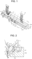
FIG. 1 is a perspective view of an air jet loom with a fixing device for a support body; -
FIG. 2 is a section view taken along a line 2-2 illustrated inFIG. 1 ; -
FIG. 3 is a front view illustrating a state where the support body is fixed to a sley; -
FIG. 4 is a side view of a fastening member and a nut; -
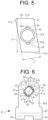
FIG. 5 is a front view of the fastening member; -
FIG. 6 is a front view of the support body; -
FIG. 7 is a perspective view of the support body; -
FIG. 8 is a schematic diagram illustrating a fastening state of the fastening member and the support body; -
FIG. 9 is a schematic diagram illustrating the fastening state of the fastening member and the support body; and -
FIG. 10 is a schematic diagram illustrating the fastening state of the fastening member and the support body. - The following will describe an embodiment of a loom with a fixing device for a support body embodied in an air jet loom with a fixing device for a support body with reference to
FIGS. 1 to 10 . In the description, a right side, a left side, an upper side, and a lower side ofFIG. 2 are referred to as a rear side, a front side, an upper side, and a lower side of the air jet loom, respectively. - As illustrated in
FIGS. 1 and 2 , anair jet loom 10 includes areed 11, asley 20, a main nozzle (not illustrated) for weft insertion, and a plurality ofsub-nozzles 12 for weft insertion. Thereed 11, the main nozzle (not illustrated) for weft insertion, and the plurality ofsub-nozzles 12 for weft insertion are fixed to thesley 20. Theair jet loom 10 has acable 13 routed therethrough. - The
air jet loom 10 includes asupport body 40 for supporting thecable 13, and a fasteningmember 30 for fixing thesupport body 40 to thesley 20. Theair jet loom 10 includes a fixing device 1 for thesupport body 40. The fixing device 1 for thesupport body 40 includes thesupport body 40 and thefastening member 30. - The
sley 20 has aninclined surface 21 and a T-shaped groove 22. Theinclined surface 21 is located adjacent to afront surface 20a of thesley 20. Thesley 20 has arear surface 20b disposed on a side opposite to thefront surface 20a in a short-length direction of thesley 20. In thesley 20, a side on which thereed 11 protrudes is referred to as an upper side of thesley 20, and a side opposite to the upper side is referred to as a lower side of thesley 20. Theinclined surface 21 is a flat surface inclined relative to the vertical direction. Theinclined surface 21 extends along theentire sley 20 in a longitudinal direction of thesley 20. The T-shaped groove 22 is opened at theinclined surface 21. The T-shaped groove 22 opened at theinclined surface 21 extends along the entire sley in the longitudinal direction of thesley 20. - As illustrated in
FIGS. 2 and3 , the T-shapedgroove 22 has a frontsurface opening portion 22a and agroove 22b. The T-shapedgroove 22 has a T-shape as viewed from an end of thesley 20 in the longitudinal direction of thesley 20. The frontsurface opening portion 22a is opened at thefront surface 20a of thesley 20. - The
groove 22b is located closer to therear surface 20b of thesley 20 than the frontsurface opening portion 22a is. Thegroove 22b has anupper wall 23, alower wall 24, an upperfront wall 25, a lowerfront wall 26, and arear wall 27. Theupper wall 23 and thelower wall 24 are in parallel with each other. The upperfront wall 25 and thelower front wall 26 are in parallel with therear wall 27. A groove width W1 of thegroove 22b has a dimension corresponding to a length of the shortest line connecting theupper wall 23 to thelower wall 24. - The front
surface opening portion 22a extends from theinclined surface 21 to a middle position between theupper wall 23 and thelower wall 24 in a direction perpendicular to thegroove 22b. The frontsurface opening portion 22a is defined by a pair ofopening forming surfaces 220a facing to each other in an up and down direction. An opening width W2 of the frontsurface opening portion 22a has a dimension corresponding to a length of a shortest line connecting the pair of theopening forming surfaces 220a facing to each other. The opening width W2 is smaller than the groove width W1. The T-shapedgroove 22 is formed so as to extend along the entire length of thesley 20. - As illustrated in
FIGS. 3, 4 , and5 , thefastening member 30 has a T-shapedhead portion 31, ashank portion 32, and a threadedportion 33. A direction in which theshank portion 32 of thefastening member 30 extends is referred to as an axial direction of theshank portion 32. - The T-shaped
head portion 31 is to be inserted through the frontsurface opening portion 22a of the T-shapedgroove 22 into thegroove 22b. The T-shapedhead portion 31 has a parallelogram shape as viewed in the axial direction of theshank portion 32. The T-shapedhead portion 31 has a pair ofshort sides 31a and a pair oflong sides 31b. A length of the shortest line connecting the pair oflong sides 31b to each other is referred to as a first length L1 of the T-shapedhead portion 31. A length of the shortest line connecting the pair ofshort sides 31a to each other is referred to as a second length L2 of the T-shapedhead portion 31. - The first length L1 of the T-shaped
head portion 31 is slightly smaller than the opening width W2 of the frontsurface opening portion 22a. This allows the T-shapedhead portion 31 to be inserted through the frontsurface opening portion 22a. A position where the T-shapedhead portion 31 is inserted into thegroove 22b through the frontsurface opening portion 22a is referred to as an insertion position of thefastening member 30. - The second length L2 of the T-shaped
head portion 31 is greater than the opening width W2 of the frontsurface opening portion 22a and slightly smaller than the groove width W1 of thegroove 22b. This allows one of theshort sides 31a to be engaged with theupper wall 23 and the other of theshort sides 31a to be engaged with thelower wall 24 when the T-shapedhead portion 31 rotates around an axial center of theshank portion 32 by a predetermined angle after the T-shapedhead portion 31 is inserted into thegroove 22b of the T-shapedgroove 22. In this way, the T-shapedhead portion 31 is placed in an engagement state. The engagement state refers to a state where the T-shapedhead portion 31 is engaged with an inner surface of thegroove 22b. A direction in which thefastening member 30 is rotated so that the T-shapedhead portion 31 is engaged with the inner surface of thegroove 22b and placed in the engagement state is referred to as an engagement direction R1. - The
shank portion 32 extends from the T-shapedhead portion 31. A diameter of theshank portion 32 is slightly smaller than the opening width W2. This allows theshank portion 32 to be inserted through the frontsurface opening portion 22a. Theshank portion 32 has twoprotrusions 34. The twoprotrusions 34 protrude from an outer peripheral surface of theshank portion 32 in a radial direction of theshank portion 32. Thus, thefastening member 30 has theprotrusions 34 protruding from theshank portion 32 in the radial direction of theshank portion 32. Each of the twoprotrusions 34 has a thin plate shape a longitudinal side of which extends in the axial direction of thefastening member 30. Theprotrusion 34 is disposed between the T-shapedhead portion 31 and the threadedportion 33 in the axial direction of thefastening member 30. Theprotrusion 34 protrudes from theshank portion 32 in a direction perpendicular to theshort sides 31a. The twoprotrusions 34 are disposed opposite to each other across theshank portion 32. Thelong sides 31b of thefastening member 30 are inclined with respect to protruding directions of theprotrusions 34 as viewed in the axial direction of thefastening member 30. Each of the twoprotrusions 34 has acontact edge 34a at one end of theprotrusion 34 in a longitudinal direction thereof close to the threadedportion 33. Thecontact edge 34a will be described later. - The threaded
portion 33 is formed on a tip end of theshank portion 32. The threadedportion 33 can be screwed through anut 35. - As illustrated in
FIGS. 3 ,6 , and7 , thesupport body 40 has amain body 41, aclamp 42, and a throughhole 50. Themain body 41 has a substantially rectangular parallelepiped block shape. - A direction in which the through
hole 50 extends through thesupport body 40 is referred to as a thickness direction X1 of thesupport body 40. Themain body 41 has afront surface 40a on one side of themain body 41 in the thickness direction X1 and arear surface 40b on the other side of themain body 41 in the thickness direction X1. Thesupport body 40 is fixed to thesley 20 with thefront surface 40a facing theinclined surface 21. Thefront surface 40a corresponds to a facing surface of thesupport body 40. - The
clamp 42 is disposed below themain body 41. Theclamp 42 has two holdingportions 43. The holdingportions 43 hold thecable 13. Thus, thecable 13 is supported by thesupport body 40. Thecable 13 corresponds to an object to be supported by thesupport body 40. The holdingportions 43 are formed so as to clamp thecable 13 from therear surface 40b of thesupport body 40. - As illustrated in
FIG. 6 , the throughhole 50 extends through themain body 41 of thesupport body 40. A diameter of the throughhole 50 is slightly greater than the diameter of theshank portion 32 and the diameter of the threadedportion 33 of thefastening member 30. The throughhole 50 is a hole formed around a central axis A1 and extending along a first imaginary circle C1 having a radius R. A circumferential direction of the first imaginary circle C1 corresponds to a circumferential direction of thesupport body 40. - The
support body 40 has two restriction surfaces 52. Each of the two restriction surfaces 52 continues to the throughhole 50. Therestriction surface 52 extends from an intermediate position of thesupport body 40 in the thickness direction X1 to therear surface 40b of thesupport body 40. Therestriction surface 52 has a rectangular shape, the longitudinal sides of which extend in the thickness direction X1 of thesupport body 40. The tworestriction surfaces 52 are located substantially opposite to each other across the central axis A1 of the throughhole 50. - As illustrated in
FIGS. 6 and7 , thesupport body 40 has twofree spaces 53 that allow theprotrusions 34 to change their positions. Each of thefree spaces 53 has a width in the circumferential direction of thesupport body 40 and extends in the thickness direction X1 of thesupport body 40. Thefree spaces 53 are open at therear surface 40b of thesupport body 40. Thefree spaces 53 are a space communicating with the throughhole 50. The twofree spaces 53 are radially opposite to each other across the throughhole 50. - The
free spaces 53 are defined by the restriction surfaces 52, two first definingsurfaces 54, and two second definingsurfaces 55, respectively. Each of the two first definingsurfaces 54 extends along the entire length of thesupport body 40 in the thickness direction X1 of thesupport body 40. Each of the first definingsurfaces 54 connects thefront surface 40a to therear surface 40b of thesupport body 40. Each of the first definingsurfaces 54 has a rectangular shape, the longitudinal sides of which extend in the thickness direction X1 of thesupport body 40. The two first definingsurfaces 54 are disposed substantially opposite to each other across the central axis A1 of the throughhole 50. The restriction surfaces 52 are spaced from their associated first definingsurfaces 54 in the circumferential direction of thesupport body 40. - Each of the two second defining
surfaces 55 connects therestriction surface 52 to the first definingsurface 54 adjacent to therestriction surface 52 in the circumferential direction of thesupport body 40. Each of the second definingsurfaces 55 extends in the thickness direction X1 of thesupport body 40. An imaginary circle formed around the central axis A1 and extending along the two second definingsurfaces 55 when thesupport body 40 is viewed in the thickness direction X1 is defined as a second imaginary circle C2. A diameter of the second imaginary circle C2 is greater than that of the first imaginary circle C1. The two second definingsurfaces 55 are disposed substantially opposite to each other across the central axis A1 of the throughhole 50. Each of thefree spaces 53 is a space outwardly recessed from the throughhole 50. - The
support body 40 has two guide surfaces 51. Each of the two guide surfaces 51 continues to the throughhole 50. Theguide surface 51 connects thefront surface 40a of thesupport body 40 to therestriction surface 52. Theguide surface 51 extends from thefront surface 40a of thesupport body 40 to an intermediate position of thesupport body 40 in the thickness direction X1. Each of the guide surfaces 51 extends from thefront surface 40a of thesupport body 40 in the circumferential direction of thesupport body 40 toward a center of thesupport body 40 in the thickness direction X1. Each of the guide surfaces 51 is a spiral surface extending spirally around the central axis A1. - Each of the guide surfaces 51 has a
first end 51a connected to thefront surface 40a of thesupport body 40, and asecond end 51b to its associatedrestriction surface 52. Each of the first ends 51a of the guide surfaces 51 is disposed at a position displaced from the correspondingsecond end 51b by approximately 90 degrees in a circumferential direction of the throughhole 50. - The
support body 40 hasopen spaces 56. Each of theopen spaces 56 is a space extending from thefront surface 40a to theguide surface 51 in the thickness direction X1 of thesupport body 40. Each of theopen spaces 56 communicates with its associatedfree space 53. - The contact edges 34a of the two
protrusions 34 are contactable with their associated guide surfaces 51. The twoprotrusions 34 are insertable into the respectivefree spaces 53. - The following will describe a method of fixing the
support body 40 to thesley 20 and operations thereof. The method and the operations will be described with reference toFIGS. 8 ,9, and 10 in which thenut 35 is not illustrated for the sake of illustration. - First, an operator places the
cable 13 to be held by the holdingportions 43 of thesupport body 40. Then, the operator arranges the T-shapedhead portion 31 so that thelong sides 31b of the T-shapedhead portion 31 are in parallel with theopening forming surfaces 220a of the frontsurface opening portion 22a. The operator moves thefastening member 30 toward thesley 20 and inserts the T-shapedhead portion 31 through the frontsurface opening portion 22a into thegroove 22b. The position of the T-shapedhead portion 31 at this time corresponds to the insertion position of thefastening member 30. - At the insertion position, the
long sides 31b of the T-shapedhead portion 31 are substantially in parallel with theupper wall 23 and thelower wall 24 as indicated with chain double-dashed lines inFIG. 3 . At the insertion position of the T-shapedhead portion 31, theshank portion 32 is supported on theopening forming surface 220a. At the insertion position of the T-shapedhead portion 31, the twoprotrusions 34 protrude from theshank portion 32 in the longitudinal direction of thesley 20. - As illustrated in
FIG. 8 , the operator inserts theshank portion 32 and the threadedportion 33 through the throughhole 50 so that the threadedportion 33 project out from therear surface 40b of thesupport body 40. Thesupport body 40 is arranged so that the holdingportions 43 of thesupport body 40 are positioned below themain body 41. In other words, thesupport body 40 is brought to a position to be attached to thesley 20. At this time, the contact edges 34a of the twoprotrusions 34 face theopen spaces 56. The twoprotrusions 34 are located closer to thesley 20 than thefront surface 40a of thesupport body 40 is. - In the above description, the
support body 40 is assembled with thefastening member 30 after the T-shapedhead portion 31 is inserted into the T-shapedgroove 22. However, inserting the T-shapedhead portion 31 and assembling thesupport body 40 need not be performed in this order. The T-shapedhead portion 31 may be inserted into the T-shapedgroove 22 after theshank portion 32 and the threadedportion 33 are inserted through the throughhole 50, the threadedportion 33 is protruded from therear surface 40b of thesupport body 40, and thesupport body 40 is assembled with thefastening member 30. - Subsequently, the operator screws the
nut 35 onto the threadedportion 33 projected out from thesupport body 40 and tighten the threadedportion 33 with thenut 35, so that thefastening member 30 is moved into thenut 35. At this time, with the contact edges 34a of therespective protrusions 34 being in sliding contact with the guide surfaces 51, part of a linear movement of thefastening member 30 in the axial direction is converted into rotation. In other words, tightening thenut 35 causes the guide surfaces 51 to guide theprotrusions 34. As a result, the T-shapedhead portion 31 rotates in the engagement direction R1, and theprotrusions 34 are placed in theopen spaces 56. - As illustrated in
FIG. 10 , theprotrusions 34 reach the restriction surfaces 52 after thefastening member 30 rotates by a predetermined angle. Then, the threadedportion 33 is further tightened with thenut 35, so that thefastening member 30 linearly moves along the restriction surfaces 52. As a result, the T-shapedhead portion 31 approaches the upperfront wall 25 and thelower front wall 26. - At the same time, the
fastening member 30 linearly moves in the axial direction of thefastening member 30 so that thefastening member 30 is spaced away from the guide surfaces 51. Theprotrusions 34 move in thefree spaces 53 so that theprotrusions 34 are spaced away from the guide surfaces 51. When thefastening member 30 is placed in the engagement state, theprotrusions 34 are positioned adjacent to the restriction surfaces 52, which restricts the rotation of thefastening member 30 in a direction opposite to the engagement direction R1. Then, the threadedportion 33 is tightened with thenut 35 even further, so that the T-shapedhead portion 31 comes in contact with the upperfront wall 25 and thelower front wall 26. As a result, thesley 20 is held between the T-shapedhead portion 31 and thesupport body 40, so that thesupport body 40 is fixed to thesley 20. - The following will describe advantageous effects of the present embodiment.
- (1) The
support body 40 has the restriction surfaces 52 and the guide surfaces 51. In this configuration, when the threadedportion 33 is tightened with thenut 35, thefastening member 30 is moved into thenut 35. At this time, theprotrusions 34 are guided along the guide surfaces 51, and part of the linear movement of thefastening member 30 in the axial direction is converted into rotation. This causes the T-shapedhead portion 31 to rotate in the engagement direction R1. - After the
fastening member 30 rotates by the predetermined angle, theprotrusions 34 reach the restriction surfaces 52. Further tightening the threadedportion 33 with thenut 35 causes thefastening member 30 to move linearly along the restriction surfaces 52, and the T-shapedhead portion 31 to approach thesley 20. - At the same time, the
fastening member 30 linearly moves in the axial direction of thefastening member 30 so that thefastening member 30 is spaced away from the guide surfaces 51. When thefastening member 30 is placed in the engagement state, theprotrusions 34 are positioned adjacent to the restriction surfaces 52, which restricts the rotation of thefastening member 30 in a direction opposite to the engagement direction R1. When the threadedportion 33 is tightened with thenut 35 even further, thesley 20 is held between thesupport body 40 and the T-shapedhead portion 31, so that thesupport body 40 is fixed to thesley 20. - According to the fixing device 1 for the
support body 40, simply tightening the threadedportion 33 with thenut 35 allows the guide surfaces 51 to change only the position of the T-shapedhead portion 31 into the engagement state without changing the position of thesupport body 40. In addition, the restriction surfaces 52 restrict rotation of thefastening member 30 in the direction opposite to the engagement direction R1. As a result, the engagement state is maintained. - In this way, for example, even while a part is being attached to the
sley 20, thesupport body 40 is unlikely to interfere with other parts attached to thesley 20. Therefore, attachment positions of the other parts need not be changed. As a result, this configuration improves the workability when thesupport body 40 is fixed to thesley 20. - (2) The guide surfaces 51 are the spiral surfaces extending spirally around the central axis A1 of the through
hole 50. This configuration allows the guide surfaces 51 to guide the contact edges 34a of theprotrusions 34 more smoothly compared to a case where, for example, the guide surfaces 51 have tapered surfaces. Therefore, this configuration suppresses a force applied to theprotrusions 34 when the contact edges 34a of theprotrusions 34 are in sliding contact with the guide surfaces 51. As a result, reliability of the guide surfaces 51 in guiding theprotrusions 34 may be improved. - (3) According to the fixing device 1 for the
support body 40, simply tightening the threadedportion 33 with thenut 35 allows the guide surfaces 51 to change only the position of the T-shapedhead portion 31 into the engagement state without changing the position of thesupport body 40. In other words, simply tightening the threadedportion 33 with thenut 35 accomplishes changing the position of the T-shapedhead portion 31, restricting the rotation of the T-shapedhead portion 31 in the direction opposite to the engagement direction R1, and fixing thesupport body 40 to thesley 20. As a result, the fixing device 1 for thesupport body 40 further improves the workability o when thesupport body 40 is fixed to thesley 20. - (4) The
support body 40 has theclamp 42 below themain body 41. Thesupport body 40 is a member having a relatively large dimension between the throughhole 50 and theclamp 42. If the position of such asupport body 40 is changed rotationally around the central axis A1, thesupport body 40 having a large radius of rotation is likely to interfere with the other parts. However, the fixing device 1 for thesupport body 40 does not change the position of thesupport body 40, which is enormously effective to thesupport body 40 having the relatively large dimension between the throughhole 50 and theclamp 42. - The embodiment according to the present invention may be modified as follows. The above-described embodiment and the following modifications may be implemented in combination with each other within a technically consistent range.
- The guide surfaces 51 may be spiral grooves that extend from the
front surface 40a to the restriction surfaces 52. In this case, theopen spaces 56 are not formed, and theprotrusions 34 have columnar shapes insertable into the spiral grooves. - The guide surfaces 51 may be inclined surfaces that extend from the
front surface 40a to the restriction surfaces 52. - The shape of the
protrusions 34 is not limited to any particular shape as long as theprotrusions 34 are able to be in sliding contact with the guide surfaces 51. - The
fastening member 30 may only have asingle protrusion 34. In this case, the number of the guide surfaces 51 may be only one, or two. - The object to be supported by the
support body 40 is not limited to the cable, but may be, for example, a sub-nozzle or a weft feeler. - The loom is not limited to the air jet loom, but may be a water jet loom, a rapier loom, or a projectile loom.
- There is provided a loom (10) with a fixing device (1) for a support body (40). The fixing device (1) includes a fastening member (30) and the support body (40). The fastening member (30) includes a protrusion (34) protruding from a shank portion (32) in a radial direction (R) of the shank portion (32). The support body (40) includes a restriction surface (52) and a guide surface (51). The restriction surface (52) is configured to restrict rotation of a T-shaped head portion (31) in a direction opposite to an engagement direction (R1) with the restriction surface (52) engaged with the protrusion (34). The guide surface (51) connects the facing surface (40a) to the restriction surface (52). The guide surface (51) guides the protrusion (34) so that the T-shaped head portion (31) rotates in the engagement direction (R1) when the threaded portion (33) is tightened with the nut (35).
Claims (2)
- A loom (10) with a fixing device (1) for a support body (40), the loom (10) including a sley (20) having a front surface (20a), a rear surface (20b), and a T-shaped groove (22), the T-shaped groove (22) having a front surface opening portion (22a) that is opened at the front surface (20a) and a groove (22b) that is located closer to the rear surface (20b) than the front surface opening portion (22a) is, the fixing device (1) comprising:a fastening member (30) having a T-shaped head portion (31) to be inserted into the T-shaped groove (22) and placed in the groove (22b), a shank portion (32) extending from the T-shaped head portion (31), and a threaded portion (33) formed on a tip end of the shank portion (32); andthe support body (40) configured to support an object to be supported, and having a facing surface (40a) facing the front surface (20a) on one side of the support body (40) in a thickness direction (X1) of the support body (40) and a through hole (50) extending through the support body (40) in the thickness direction (X1),wherein the T-shaped head portion (31) is placed in an engagement state in which the T-shaped head portion (31) is engaged with an upper wall (23) and a lower wall (24) of the groove (22b) when the fastening member (30) is rotated by a predetermined angle in an engagement direction (R1) in a state where the T-shaped head portion (31) is inserted through the front surface opening portion (22a) into the groove (22b), the facing surface (40a) faces the front surface (20a) of the sley (20), and the threaded portion (33) is inserted through the through hole (50) of the support body (40),wherein the threaded portion (33) is tightened with a nut (35) to cause the sley (20) to be held between the support body (40) and the T-shaped head portion (31) so that the support body (40) is fixed to the sley (20),wherein the fastening member (30) includes a protrusion (34) protruding from the shank portion (32) in a radial direction of the shank portion (32), andwherein the support body (40) includes a restriction surface (52) configured to restrict rotation of the T-shaped head portion (31) in a direction opposite to the engagement direction (R1) with the restriction surface (52) engaged with the protrusion (34) in the engagement state, characterized in thatthe support body (40) includes a guide surface (51) connecting the facing surface (40a) to the restriction surface (52), andthe guide surface (51) is configured to guide the protrusion (34) so that the T-shaped head portion (31) rotates in the engagement direction (R1) when the threaded portion (33) is tightened with the nut (35).
- The loom (10) with the fixing device (1) for the support body (40) according to claim 1, characterized in that
the guide surface (51) includes a spiral surface extending spirally around a central axis (A1) of the through hole (50).
Applications Claiming Priority (1)
| Application Number | Priority Date | Filing Date | Title |
|---|---|---|---|
| JP2021209840A JP7567770B2 (en) | 2021-12-23 | 2021-12-23 | Fixing device for supports in a weaving machine |
Publications (2)
| Publication Number | Publication Date |
|---|---|
| EP4202096A1 true EP4202096A1 (en) | 2023-06-28 |
| EP4202096B1 EP4202096B1 (en) | 2024-09-18 |
Family
ID=82492388
Family Applications (1)
| Application Number | Title | Priority Date | Filing Date |
|---|---|---|---|
| EP22182497.2A Active EP4202096B1 (en) | 2021-12-23 | 2022-07-01 | Loom with fixing device for support body |
Country Status (3)
| Country | Link |
|---|---|
| EP (1) | EP4202096B1 (en) |
| JP (1) | JP7567770B2 (en) |
| CN (1) | CN116334818A (en) |
Families Citing this family (1)
| Publication number | Priority date | Publication date | Assignee | Title |
|---|---|---|---|---|
| KR102792131B1 (en) * | 2023-12-31 | 2025-04-10 | (주)전인엔지니어링건축사사무소 | Reverse Rotation T-bolt for Fastening Exterior Panels |
Citations (2)
| Publication number | Priority date | Publication date | Assignee | Title |
|---|---|---|---|---|
| JP3408698B2 (en) * | 1996-08-09 | 2003-05-19 | 津田駒工業株式会社 | Fastening and fixing device for target members in loom |
| JP2014201864A (en) | 2013-04-10 | 2014-10-27 | 株式会社豊田自動織機 | Fixing device of supporting body in weaving machine |
Family Cites Families (8)
| Publication number | Priority date | Publication date | Assignee | Title |
|---|---|---|---|---|
| JPS526185A (en) * | 1975-07-03 | 1977-01-18 | Taiichi Oka | Clamp tool |
| BE1003804A3 (en) * | 1989-04-28 | 1992-06-16 | Picanol Nv | DEVICE FOR FIXING A COMPONENT TO THE DRAWER of a loom. |
| JPH063536U (en) * | 1992-06-19 | 1994-01-18 | ブラザー工業株式会社 | Mounting device |
| JPH07173742A (en) * | 1993-12-17 | 1995-07-11 | Tsudakoma Corp | Mounting apparatus for objective members in loom |
| JPH08246298A (en) * | 1995-03-08 | 1996-09-24 | Toyota Autom Loom Works Ltd | Apparatus for attaching parts to sleigh of loom |
| JP3532559B1 (en) * | 2003-04-04 | 2004-05-31 | 光洋器材株式会社 | Blind bolts and blind nuts |
| CN201705760U (en) * | 2010-05-24 | 2011-01-12 | 镇江奇佩支吊架有限公司 | Locking device for fast-assembled flange groove mechanism |
| CN101852231B (en) * | 2010-05-24 | 2011-11-30 | 镇江奇佩支吊架有限公司 | Quick locking device for flange groove mechanism |
-
2021
- 2021-12-23 JP JP2021209840A patent/JP7567770B2/en active Active
-
2022
- 2022-07-01 EP EP22182497.2A patent/EP4202096B1/en active Active
- 2022-08-22 CN CN202211006277.6A patent/CN116334818A/en active Pending
Patent Citations (2)
| Publication number | Priority date | Publication date | Assignee | Title |
|---|---|---|---|---|
| JP3408698B2 (en) * | 1996-08-09 | 2003-05-19 | 津田駒工業株式会社 | Fastening and fixing device for target members in loom |
| JP2014201864A (en) | 2013-04-10 | 2014-10-27 | 株式会社豊田自動織機 | Fixing device of supporting body in weaving machine |
Also Published As
| Publication number | Publication date |
|---|---|
| EP4202096B1 (en) | 2024-09-18 |
| JP7567770B2 (en) | 2024-10-16 |
| JP2023094392A (en) | 2023-07-05 |
| CN116334818A (en) | 2023-06-27 |
Similar Documents
| Publication | Publication Date | Title |
|---|---|---|
| US6883762B2 (en) | Clamp | |
| EP4202096B1 (en) | Loom with fixing device for support body | |
| NO339633B1 (en) | Cable entry device | |
| KR20080109018A (en) | How to Install Optical Fiber Cords in the Optical Connector and the Optical Connector | |
| KR20150020091A (en) | Wall feed-through element for a fluid line and wall feed-through | |
| EP2167280A1 (en) | Attachment mechanism | |
| JP2001280323A (en) | Rotating nut | |
| US4732178A (en) | Loom | |
| US20220305573A1 (en) | Milling cutter | |
| US20160190755A1 (en) | Connector | |
| US8082820B2 (en) | Fastening system | |
| US12441559B2 (en) | Feeding device for guiding and providing one-piece ties | |
| WO2006114587A1 (en) | Cable gland assembly and seal therefor | |
| KR0157352B1 (en) | Fixture | |
| EP3967892B1 (en) | Fastener of weaving machine and fixing device for support of the weaving machine | |
| JP2022037416A (en) | Connector holder and wire harness with connector holder | |
| JP6071149B2 (en) | Vehicle door handle device assembly structure, vehicle door handle device assembly method, and vehicle door handle device | |
| JP7818148B2 (en) | Mounting structure and fixtures | |
| US20240401991A1 (en) | Sensor mounting structure | |
| JP4071844B2 (en) | Thread clamp used for rapier, rapier with thread clamp and rapier loom | |
| JP3466100B2 (en) | Wiring box and wiring box device | |
| US20240209886A1 (en) | Clip and clip attachment structure | |
| CN217992318U (en) | Auxiliary device for mounting drift tube of linear accelerator | |
| US12508660B2 (en) | Rotary cutting tool and holding element for a rotary cutting tool | |
| US20240351111A1 (en) | Cutting tool |
Legal Events
| Date | Code | Title | Description |
|---|---|---|---|
| PUAI | Public reference made under article 153(3) epc to a published international application that has entered the european phase |
Free format text: ORIGINAL CODE: 0009012 |
|
| STAA | Information on the status of an ep patent application or granted ep patent |
Free format text: STATUS: REQUEST FOR EXAMINATION WAS MADE |
|
| 17P | Request for examination filed |
Effective date: 20220701 |
|
| AK | Designated contracting states |
Kind code of ref document: A1 Designated state(s): AL AT BE BG CH CY CZ DE DK EE ES FI FR GB GR HR HU IE IS IT LI LT LU LV MC MK MT NL NO PL PT RO RS SE SI SK SM TR |
|
| GRAP | Despatch of communication of intention to grant a patent |
Free format text: ORIGINAL CODE: EPIDOSNIGR1 |
|
| STAA | Information on the status of an ep patent application or granted ep patent |
Free format text: STATUS: GRANT OF PATENT IS INTENDED |
|
| RIC1 | Information provided on ipc code assigned before grant |
Ipc: D03D 47/30 20060101ALI20240325BHEP Ipc: D03D 49/60 20060101AFI20240325BHEP |
|
| INTG | Intention to grant announced |
Effective date: 20240410 |
|
| GRAS | Grant fee paid |
Free format text: ORIGINAL CODE: EPIDOSNIGR3 |
|
| P01 | Opt-out of the competence of the unified patent court (upc) registered |
Free format text: CASE NUMBER: APP_38589/2024 Effective date: 20240627 |
|
| GRAA | (expected) grant |
Free format text: ORIGINAL CODE: 0009210 |
|
| STAA | Information on the status of an ep patent application or granted ep patent |
Free format text: STATUS: THE PATENT HAS BEEN GRANTED |
|
| AK | Designated contracting states |
Kind code of ref document: B1 Designated state(s): AL AT BE BG CH CY CZ DE DK EE ES FI FR GB GR HR HU IE IS IT LI LT LU LV MC MK MT NL NO PL PT RO RS SE SI SK SM TR |
|
| REG | Reference to a national code |
Ref country code: GB Ref legal event code: FG4D |
|
| REG | Reference to a national code |
Ref country code: CH Ref legal event code: EP |
|
| REG | Reference to a national code |
Ref country code: IE Ref legal event code: FG4D |
|
| REG | Reference to a national code |
Ref country code: DE Ref legal event code: R096 Ref document number: 602022006152 Country of ref document: DE |
|
| REG | Reference to a national code |
Ref country code: LT Ref legal event code: MG9D |
|
| PG25 | Lapsed in a contracting state [announced via postgrant information from national office to epo] |
Ref country code: NO Free format text: LAPSE BECAUSE OF FAILURE TO SUBMIT A TRANSLATION OF THE DESCRIPTION OR TO PAY THE FEE WITHIN THE PRESCRIBED TIME-LIMIT Effective date: 20241218 |
|
| PG25 | Lapsed in a contracting state [announced via postgrant information from national office to epo] |
Ref country code: GR Free format text: LAPSE BECAUSE OF FAILURE TO SUBMIT A TRANSLATION OF THE DESCRIPTION OR TO PAY THE FEE WITHIN THE PRESCRIBED TIME-LIMIT Effective date: 20241219 Ref country code: FI Free format text: LAPSE BECAUSE OF FAILURE TO SUBMIT A TRANSLATION OF THE DESCRIPTION OR TO PAY THE FEE WITHIN THE PRESCRIBED TIME-LIMIT Effective date: 20240918 |
|
| PG25 | Lapsed in a contracting state [announced via postgrant information from national office to epo] |
Ref country code: BG Free format text: LAPSE BECAUSE OF FAILURE TO SUBMIT A TRANSLATION OF THE DESCRIPTION OR TO PAY THE FEE WITHIN THE PRESCRIBED TIME-LIMIT Effective date: 20240918 |
|
| PG25 | Lapsed in a contracting state [announced via postgrant information from national office to epo] |
Ref country code: LV Free format text: LAPSE BECAUSE OF FAILURE TO SUBMIT A TRANSLATION OF THE DESCRIPTION OR TO PAY THE FEE WITHIN THE PRESCRIBED TIME-LIMIT Effective date: 20240918 |
|
| PG25 | Lapsed in a contracting state [announced via postgrant information from national office to epo] |
Ref country code: HR Free format text: LAPSE BECAUSE OF FAILURE TO SUBMIT A TRANSLATION OF THE DESCRIPTION OR TO PAY THE FEE WITHIN THE PRESCRIBED TIME-LIMIT Effective date: 20240918 |
|
| REG | Reference to a national code |
Ref country code: NL Ref legal event code: MP Effective date: 20240918 |
|
| PG25 | Lapsed in a contracting state [announced via postgrant information from national office to epo] |
Ref country code: RS Free format text: LAPSE BECAUSE OF FAILURE TO SUBMIT A TRANSLATION OF THE DESCRIPTION OR TO PAY THE FEE WITHIN THE PRESCRIBED TIME-LIMIT Effective date: 20241218 |
|
| PG25 | Lapsed in a contracting state [announced via postgrant information from national office to epo] |
Ref country code: RS Free format text: LAPSE BECAUSE OF FAILURE TO SUBMIT A TRANSLATION OF THE DESCRIPTION OR TO PAY THE FEE WITHIN THE PRESCRIBED TIME-LIMIT Effective date: 20241218 Ref country code: NO Free format text: LAPSE BECAUSE OF FAILURE TO SUBMIT A TRANSLATION OF THE DESCRIPTION OR TO PAY THE FEE WITHIN THE PRESCRIBED TIME-LIMIT Effective date: 20241218 Ref country code: LV Free format text: LAPSE BECAUSE OF FAILURE TO SUBMIT A TRANSLATION OF THE DESCRIPTION OR TO PAY THE FEE WITHIN THE PRESCRIBED TIME-LIMIT Effective date: 20240918 Ref country code: HR Free format text: LAPSE BECAUSE OF FAILURE TO SUBMIT A TRANSLATION OF THE DESCRIPTION OR TO PAY THE FEE WITHIN THE PRESCRIBED TIME-LIMIT Effective date: 20240918 Ref country code: GR Free format text: LAPSE BECAUSE OF FAILURE TO SUBMIT A TRANSLATION OF THE DESCRIPTION OR TO PAY THE FEE WITHIN THE PRESCRIBED TIME-LIMIT Effective date: 20241219 Ref country code: FI Free format text: LAPSE BECAUSE OF FAILURE TO SUBMIT A TRANSLATION OF THE DESCRIPTION OR TO PAY THE FEE WITHIN THE PRESCRIBED TIME-LIMIT Effective date: 20240918 Ref country code: BG Free format text: LAPSE BECAUSE OF FAILURE TO SUBMIT A TRANSLATION OF THE DESCRIPTION OR TO PAY THE FEE WITHIN THE PRESCRIBED TIME-LIMIT Effective date: 20240918 |
|
| REG | Reference to a national code |
Ref country code: AT Ref legal event code: MK05 Ref document number: 1724768 Country of ref document: AT Kind code of ref document: T Effective date: 20240918 |
|
| PG25 | Lapsed in a contracting state [announced via postgrant information from national office to epo] |
Ref country code: NL Free format text: LAPSE BECAUSE OF FAILURE TO SUBMIT A TRANSLATION OF THE DESCRIPTION OR TO PAY THE FEE WITHIN THE PRESCRIBED TIME-LIMIT Effective date: 20240918 |
|
| PG25 | Lapsed in a contracting state [announced via postgrant information from national office to epo] |
Ref country code: IS Free format text: LAPSE BECAUSE OF FAILURE TO SUBMIT A TRANSLATION OF THE DESCRIPTION OR TO PAY THE FEE WITHIN THE PRESCRIBED TIME-LIMIT Effective date: 20250118 Ref country code: PT Free format text: LAPSE BECAUSE OF FAILURE TO SUBMIT A TRANSLATION OF THE DESCRIPTION OR TO PAY THE FEE WITHIN THE PRESCRIBED TIME-LIMIT Effective date: 20250120 |
|
| PG25 | Lapsed in a contracting state [announced via postgrant information from national office to epo] |
Ref country code: RO Free format text: LAPSE BECAUSE OF FAILURE TO SUBMIT A TRANSLATION OF THE DESCRIPTION OR TO PAY THE FEE WITHIN THE PRESCRIBED TIME-LIMIT Effective date: 20240918 Ref country code: SM Free format text: LAPSE BECAUSE OF FAILURE TO SUBMIT A TRANSLATION OF THE DESCRIPTION OR TO PAY THE FEE WITHIN THE PRESCRIBED TIME-LIMIT Effective date: 20240918 |
|
| PG25 | Lapsed in a contracting state [announced via postgrant information from national office to epo] |
Ref country code: ES Free format text: LAPSE BECAUSE OF FAILURE TO SUBMIT A TRANSLATION OF THE DESCRIPTION OR TO PAY THE FEE WITHIN THE PRESCRIBED TIME-LIMIT Effective date: 20240918 |
|
| PG25 | Lapsed in a contracting state [announced via postgrant information from national office to epo] |
Ref country code: AT Free format text: LAPSE BECAUSE OF FAILURE TO SUBMIT A TRANSLATION OF THE DESCRIPTION OR TO PAY THE FEE WITHIN THE PRESCRIBED TIME-LIMIT Effective date: 20240918 Ref country code: EE Free format text: LAPSE BECAUSE OF FAILURE TO SUBMIT A TRANSLATION OF THE DESCRIPTION OR TO PAY THE FEE WITHIN THE PRESCRIBED TIME-LIMIT Effective date: 20240918 |
|
| PG25 | Lapsed in a contracting state [announced via postgrant information from national office to epo] |
Ref country code: CZ Free format text: LAPSE BECAUSE OF FAILURE TO SUBMIT A TRANSLATION OF THE DESCRIPTION OR TO PAY THE FEE WITHIN THE PRESCRIBED TIME-LIMIT Effective date: 20240918 Ref country code: PL Free format text: LAPSE BECAUSE OF FAILURE TO SUBMIT A TRANSLATION OF THE DESCRIPTION OR TO PAY THE FEE WITHIN THE PRESCRIBED TIME-LIMIT Effective date: 20240918 |
|
| PG25 | Lapsed in a contracting state [announced via postgrant information from national office to epo] |
Ref country code: SK Free format text: LAPSE BECAUSE OF FAILURE TO SUBMIT A TRANSLATION OF THE DESCRIPTION OR TO PAY THE FEE WITHIN THE PRESCRIBED TIME-LIMIT Effective date: 20240918 |
|
| REG | Reference to a national code |
Ref country code: DE Ref legal event code: R097 Ref document number: 602022006152 Country of ref document: DE |
|
| PG25 | Lapsed in a contracting state [announced via postgrant information from national office to epo] |
Ref country code: DK Free format text: LAPSE BECAUSE OF FAILURE TO SUBMIT A TRANSLATION OF THE DESCRIPTION OR TO PAY THE FEE WITHIN THE PRESCRIBED TIME-LIMIT Effective date: 20240918 |
|
| PGFP | Annual fee paid to national office [announced via postgrant information from national office to epo] |
Ref country code: BE Payment date: 20250619 Year of fee payment: 4 |
|
| PLBE | No opposition filed within time limit |
Free format text: ORIGINAL CODE: 0009261 |
|
| STAA | Information on the status of an ep patent application or granted ep patent |
Free format text: STATUS: NO OPPOSITION FILED WITHIN TIME LIMIT |
|
| 26N | No opposition filed |
Effective date: 20250619 |
|
| PG25 | Lapsed in a contracting state [announced via postgrant information from national office to epo] |
Ref country code: SE Free format text: LAPSE BECAUSE OF FAILURE TO SUBMIT A TRANSLATION OF THE DESCRIPTION OR TO PAY THE FEE WITHIN THE PRESCRIBED TIME-LIMIT Effective date: 20240918 |
|
| PGFP | Annual fee paid to national office [announced via postgrant information from national office to epo] |
Ref country code: DE Payment date: 20250528 Year of fee payment: 4 |
|
| PGFP | Annual fee paid to national office [announced via postgrant information from national office to epo] |
Ref country code: IT Payment date: 20250731 Year of fee payment: 4 |
|
| REG | Reference to a national code |
Ref country code: CH Ref legal event code: H13 Free format text: ST27 STATUS EVENT CODE: U-0-0-H10-H13 (AS PROVIDED BY THE NATIONAL OFFICE) Effective date: 20260224 |
|
| PG25 | Lapsed in a contracting state [announced via postgrant information from national office to epo] |
Ref country code: LU Free format text: LAPSE BECAUSE OF NON-PAYMENT OF DUE FEES Effective date: 20250701 |
|
| PG25 | Lapsed in a contracting state [announced via postgrant information from national office to epo] |
Ref country code: FR Free format text: LAPSE BECAUSE OF NON-PAYMENT OF DUE FEES Effective date: 20250731 |
|
| PG25 | Lapsed in a contracting state [announced via postgrant information from national office to epo] |
Ref country code: CH Free format text: LAPSE BECAUSE OF NON-PAYMENT OF DUE FEES Effective date: 20250731 |