EP4202080A1 - Method of forming protective coating - Google Patents
Method of forming protective coating Download PDFInfo
- Publication number
- EP4202080A1 EP4202080A1 EP22208968.2A EP22208968A EP4202080A1 EP 4202080 A1 EP4202080 A1 EP 4202080A1 EP 22208968 A EP22208968 A EP 22208968A EP 4202080 A1 EP4202080 A1 EP 4202080A1
- Authority
- EP
- European Patent Office
- Prior art keywords
- aluminium
- phase
- basecoat
- substrate
- protective coating
- Prior art date
- Legal status (The legal status is an assumption and is not a legal conclusion. Google has not performed a legal analysis and makes no representation as to the accuracy of the status listed.)
- Pending
Links
- 239000011253 protective coating Substances 0.000 title claims abstract description 92
- 238000000034 method Methods 0.000 title claims abstract description 61
- 239000004411 aluminium Substances 0.000 claims abstract description 111
- 229910052782 aluminium Inorganic materials 0.000 claims abstract description 111
- XAGFODPZIPBFFR-UHFFFAOYSA-N aluminium Chemical compound [Al] XAGFODPZIPBFFR-UHFFFAOYSA-N 0.000 claims abstract description 111
- 239000000758 substrate Substances 0.000 claims abstract description 103
- 239000000203 mixture Substances 0.000 claims abstract description 71
- 238000006243 chemical reaction Methods 0.000 claims abstract description 46
- 238000010438 heat treatment Methods 0.000 claims abstract description 35
- 229910052729 chemical element Inorganic materials 0.000 claims abstract description 23
- PXHVJJICTQNCMI-UHFFFAOYSA-N Nickel Chemical compound [Ni] PXHVJJICTQNCMI-UHFFFAOYSA-N 0.000 claims description 36
- NBIIXXVUZAFLBC-UHFFFAOYSA-N Phosphoric acid Chemical compound OP(O)(O)=O NBIIXXVUZAFLBC-UHFFFAOYSA-N 0.000 claims description 29
- 239000011230 binding agent Substances 0.000 claims description 27
- 229910000147 aluminium phosphate Inorganic materials 0.000 claims description 18
- 229910052759 nickel Inorganic materials 0.000 claims description 18
- WNROFYMDJYEPJX-UHFFFAOYSA-K aluminium hydroxide Chemical compound [OH-].[OH-].[OH-].[Al+3] WNROFYMDJYEPJX-UHFFFAOYSA-K 0.000 claims description 14
- 229910021502 aluminium hydroxide Inorganic materials 0.000 claims description 14
- 150000004820 halides Chemical class 0.000 claims description 14
- VYZAMTAEIAYCRO-UHFFFAOYSA-N Chromium Chemical compound [Cr] VYZAMTAEIAYCRO-UHFFFAOYSA-N 0.000 claims description 11
- 229910052804 chromium Inorganic materials 0.000 claims description 11
- 239000011651 chromium Substances 0.000 claims description 11
- 229910000838 Al alloy Inorganic materials 0.000 claims description 10
- NPXOKRUENSOPAO-UHFFFAOYSA-N Raney nickel Chemical compound [Al].[Ni] NPXOKRUENSOPAO-UHFFFAOYSA-N 0.000 claims description 9
- RPUZVWKKWXPKIP-UHFFFAOYSA-H dialuminum;hydrogen phosphate Chemical compound [Al+3].[Al+3].OP([O-])([O-])=O.OP([O-])([O-])=O.OP([O-])([O-])=O RPUZVWKKWXPKIP-UHFFFAOYSA-H 0.000 claims description 9
- 229910000907 nickel aluminide Inorganic materials 0.000 claims description 9
- -1 aluminium-manganese Chemical compound 0.000 claims description 7
- NLXLAEXVIDQMFP-UHFFFAOYSA-N Ammonia chloride Chemical compound [NH4+].[Cl-] NLXLAEXVIDQMFP-UHFFFAOYSA-N 0.000 claims description 6
- 229910052710 silicon Inorganic materials 0.000 claims description 6
- 239000010703 silicon Substances 0.000 claims description 6
- 229910052715 tantalum Inorganic materials 0.000 claims description 6
- GUVRBAGPIYLISA-UHFFFAOYSA-N tantalum atom Chemical compound [Ta] GUVRBAGPIYLISA-UHFFFAOYSA-N 0.000 claims description 6
- QCWXUUIWCKQGHC-UHFFFAOYSA-N Zirconium Chemical compound [Zr] QCWXUUIWCKQGHC-UHFFFAOYSA-N 0.000 claims description 5
- 229910052735 hafnium Inorganic materials 0.000 claims description 5
- VBJZVLUMGGDVMO-UHFFFAOYSA-N hafnium atom Chemical compound [Hf] VBJZVLUMGGDVMO-UHFFFAOYSA-N 0.000 claims description 5
- 229910052758 niobium Inorganic materials 0.000 claims description 5
- 239000010955 niobium Substances 0.000 claims description 5
- GUCVJGMIXFAOAE-UHFFFAOYSA-N niobium atom Chemical compound [Nb] GUCVJGMIXFAOAE-UHFFFAOYSA-N 0.000 claims description 5
- 229910052726 zirconium Inorganic materials 0.000 claims description 5
- 229910021586 Nickel(II) chloride Inorganic materials 0.000 claims description 4
- XUIMIQQOPSSXEZ-UHFFFAOYSA-N Silicon Chemical compound [Si] XUIMIQQOPSSXEZ-UHFFFAOYSA-N 0.000 claims description 4
- ZCDOYSPFYFSLEW-UHFFFAOYSA-N chromate(2-) Chemical class [O-][Cr]([O-])(=O)=O ZCDOYSPFYFSLEW-UHFFFAOYSA-N 0.000 claims description 4
- QMMRZOWCJAIUJA-UHFFFAOYSA-L nickel dichloride Chemical compound Cl[Ni]Cl QMMRZOWCJAIUJA-UHFFFAOYSA-L 0.000 claims description 4
- 238000003756 stirring Methods 0.000 claims description 4
- 229910052727 yttrium Inorganic materials 0.000 claims description 4
- VWQVUPCCIRVNHF-UHFFFAOYSA-N yttrium atom Chemical compound [Y] VWQVUPCCIRVNHF-UHFFFAOYSA-N 0.000 claims description 4
- 229910000789 Aluminium-silicon alloy Inorganic materials 0.000 claims description 3
- 229910000599 Cr alloy Inorganic materials 0.000 claims description 3
- 229910000914 Mn alloy Inorganic materials 0.000 claims description 3
- 229910001257 Nb alloy Inorganic materials 0.000 claims description 3
- 229910001362 Ta alloys Inorganic materials 0.000 claims description 3
- QRRWWGNBSQSBAM-UHFFFAOYSA-N alumane;chromium Chemical compound [AlH3].[Cr] QRRWWGNBSQSBAM-UHFFFAOYSA-N 0.000 claims description 3
- PEQFPKIXNHTCSJ-UHFFFAOYSA-N alumane;niobium Chemical compound [AlH3].[Nb] PEQFPKIXNHTCSJ-UHFFFAOYSA-N 0.000 claims description 3
- 235000019270 ammonium chloride Nutrition 0.000 claims description 3
- 239000000788 chromium alloy Substances 0.000 claims description 3
- GVPFVAHMJGGAJG-UHFFFAOYSA-L cobalt dichloride Chemical compound [Cl-].[Cl-].[Co+2] GVPFVAHMJGGAJG-UHFFFAOYSA-L 0.000 claims description 3
- 150000003013 phosphoric acid derivatives Chemical class 0.000 claims description 3
- WPBNNNQJVZRUHP-UHFFFAOYSA-L manganese(2+);methyl n-[[2-(methoxycarbonylcarbamothioylamino)phenyl]carbamothioyl]carbamate;n-[2-(sulfidocarbothioylamino)ethyl]carbamodithioate Chemical compound [Mn+2].[S-]C(=S)NCCNC([S-])=S.COC(=O)NC(=S)NC1=CC=CC=C1NC(=S)NC(=O)OC WPBNNNQJVZRUHP-UHFFFAOYSA-L 0.000 claims 1
- 239000007789 gas Substances 0.000 description 44
- 230000015572 biosynthetic process Effects 0.000 description 23
- 238000005275 alloying Methods 0.000 description 18
- 229910000601 superalloy Inorganic materials 0.000 description 15
- 238000000576 coating method Methods 0.000 description 14
- XKRFYHLGVUSROY-UHFFFAOYSA-N Argon Chemical compound [Ar] XKRFYHLGVUSROY-UHFFFAOYSA-N 0.000 description 10
- 150000002500 ions Chemical class 0.000 description 10
- 230000007797 corrosion Effects 0.000 description 9
- 238000005260 corrosion Methods 0.000 description 9
- 239000000463 material Substances 0.000 description 9
- 239000011248 coating agent Substances 0.000 description 8
- RTAQQCXQSZGOHL-UHFFFAOYSA-N Titanium Chemical compound [Ti] RTAQQCXQSZGOHL-UHFFFAOYSA-N 0.000 description 6
- 229910045601 alloy Inorganic materials 0.000 description 6
- 239000000956 alloy Substances 0.000 description 6
- 230000007613 environmental effect Effects 0.000 description 6
- 230000005496 eutectics Effects 0.000 description 6
- 239000010936 titanium Substances 0.000 description 6
- 229910052719 titanium Inorganic materials 0.000 description 6
- PMZURENOXWZQFD-UHFFFAOYSA-L Sodium Sulfate Chemical compound [Na+].[Na+].[O-]S([O-])(=O)=O PMZURENOXWZQFD-UHFFFAOYSA-L 0.000 description 5
- 229910052786 argon Inorganic materials 0.000 description 5
- 229910017052 cobalt Inorganic materials 0.000 description 5
- 239000010941 cobalt Substances 0.000 description 5
- GUTLYIVDDKVIGB-UHFFFAOYSA-N cobalt atom Chemical compound [Co] GUTLYIVDDKVIGB-UHFFFAOYSA-N 0.000 description 5
- 238000002485 combustion reaction Methods 0.000 description 5
- 238000002844 melting Methods 0.000 description 5
- 230000008018 melting Effects 0.000 description 5
- 230000003647 oxidation Effects 0.000 description 5
- 238000007254 oxidation reaction Methods 0.000 description 5
- 230000001141 propulsive effect Effects 0.000 description 5
- 238000011282 treatment Methods 0.000 description 5
- PWHULOQIROXLJO-UHFFFAOYSA-N Manganese Chemical compound [Mn] PWHULOQIROXLJO-UHFFFAOYSA-N 0.000 description 4
- 229910019142 PO4 Inorganic materials 0.000 description 4
- 230000002159 abnormal effect Effects 0.000 description 4
- ILRRQNADMUWWFW-UHFFFAOYSA-K aluminium phosphate Chemical compound O1[Al]2OP1(=O)O2 ILRRQNADMUWWFW-UHFFFAOYSA-K 0.000 description 4
- 229940001007 aluminium phosphate Drugs 0.000 description 4
- 238000000151 deposition Methods 0.000 description 4
- 229910052748 manganese Inorganic materials 0.000 description 4
- 239000011572 manganese Substances 0.000 description 4
- 239000010452 phosphate Substances 0.000 description 4
- 235000021317 phosphate Nutrition 0.000 description 4
- 230000008569 process Effects 0.000 description 4
- 239000000126 substance Substances 0.000 description 4
- XLYOFNOQVPJJNP-UHFFFAOYSA-N water Substances O XLYOFNOQVPJJNP-UHFFFAOYSA-N 0.000 description 4
- ZOKXTWBITQBERF-UHFFFAOYSA-N Molybdenum Chemical compound [Mo] ZOKXTWBITQBERF-UHFFFAOYSA-N 0.000 description 3
- 238000007792 addition Methods 0.000 description 3
- 230000001419 dependent effect Effects 0.000 description 3
- 229910052750 molybdenum Inorganic materials 0.000 description 3
- 239000011733 molybdenum Substances 0.000 description 3
- 239000002694 phosphate binding agent Substances 0.000 description 3
- 239000000843 powder Substances 0.000 description 3
- 239000002002 slurry Substances 0.000 description 3
- 229910052938 sodium sulfate Inorganic materials 0.000 description 3
- IJGRMHOSHXDMSA-UHFFFAOYSA-N Atomic nitrogen Chemical compound N#N IJGRMHOSHXDMSA-UHFFFAOYSA-N 0.000 description 2
- ZAMOUSCENKQFHK-UHFFFAOYSA-N Chlorine atom Chemical compound [Cl] ZAMOUSCENKQFHK-UHFFFAOYSA-N 0.000 description 2
- XEEYBQQBJWHFJM-UHFFFAOYSA-N Iron Chemical compound [Fe] XEEYBQQBJWHFJM-UHFFFAOYSA-N 0.000 description 2
- 239000004698 Polyethylene Substances 0.000 description 2
- VYPSYNLAJGMNEJ-UHFFFAOYSA-N Silicium dioxide Chemical compound O=[Si]=O VYPSYNLAJGMNEJ-UHFFFAOYSA-N 0.000 description 2
- 239000004480 active ingredient Substances 0.000 description 2
- 230000015556 catabolic process Effects 0.000 description 2
- 230000008859 change Effects 0.000 description 2
- 238000005229 chemical vapour deposition Methods 0.000 description 2
- 239000000460 chlorine Substances 0.000 description 2
- 229910052801 chlorine Inorganic materials 0.000 description 2
- 230000008021 deposition Effects 0.000 description 2
- 239000003989 dielectric material Substances 0.000 description 2
- 238000003618 dip coating Methods 0.000 description 2
- 238000004090 dissolution Methods 0.000 description 2
- 238000011065 in-situ storage Methods 0.000 description 2
- 229910001026 inconel Inorganic materials 0.000 description 2
- 239000011261 inert gas Substances 0.000 description 2
- 238000010849 ion bombardment Methods 0.000 description 2
- 229910052751 metal Inorganic materials 0.000 description 2
- 239000002184 metal Substances 0.000 description 2
- NBIIXXVUZAFLBC-UHFFFAOYSA-K phosphate Chemical compound [O-]P([O-])([O-])=O NBIIXXVUZAFLBC-UHFFFAOYSA-K 0.000 description 2
- 229920001343 polytetrafluoroethylene Polymers 0.000 description 2
- 239000004810 polytetrafluoroethylene Substances 0.000 description 2
- 230000005855 radiation Effects 0.000 description 2
- 150000003839 salts Chemical class 0.000 description 2
- 235000011152 sodium sulphate Nutrition 0.000 description 2
- 239000007921 spray Substances 0.000 description 2
- 230000001960 triggered effect Effects 0.000 description 2
- QGZKDVFQNNGYKY-UHFFFAOYSA-N Ammonia Chemical compound N QGZKDVFQNNGYKY-UHFFFAOYSA-N 0.000 description 1
- ZOXJGFHDIHLPTG-UHFFFAOYSA-N Boron Chemical compound [B] ZOXJGFHDIHLPTG-UHFFFAOYSA-N 0.000 description 1
- OKTJSMMVPCPJKN-UHFFFAOYSA-N Carbon Chemical compound [C] OKTJSMMVPCPJKN-UHFFFAOYSA-N 0.000 description 1
- 229910052684 Cerium Inorganic materials 0.000 description 1
- MBMLMWLHJBBADN-UHFFFAOYSA-N Ferrous sulfide Chemical compound [Fe]=S MBMLMWLHJBBADN-UHFFFAOYSA-N 0.000 description 1
- FYYHWMGAXLPEAU-UHFFFAOYSA-N Magnesium Chemical compound [Mg] FYYHWMGAXLPEAU-UHFFFAOYSA-N 0.000 description 1
- 239000007832 Na2SO4 Substances 0.000 description 1
- 230000004913 activation Effects 0.000 description 1
- 239000000443 aerosol Substances 0.000 description 1
- PNEYBMLMFCGWSK-UHFFFAOYSA-N aluminium oxide Inorganic materials [O-2].[O-2].[O-2].[Al+3].[Al+3] PNEYBMLMFCGWSK-UHFFFAOYSA-N 0.000 description 1
- 230000009286 beneficial effect Effects 0.000 description 1
- 238000005422 blasting Methods 0.000 description 1
- 229910052796 boron Inorganic materials 0.000 description 1
- 229910052799 carbon Inorganic materials 0.000 description 1
- UBAZGMLMVVQSCD-UHFFFAOYSA-N carbon dioxide;molecular oxygen Chemical compound O=O.O=C=O UBAZGMLMVVQSCD-UHFFFAOYSA-N 0.000 description 1
- 239000000969 carrier Substances 0.000 description 1
- 239000000919 ceramic Substances 0.000 description 1
- GWXLDORMOJMVQZ-UHFFFAOYSA-N cerium Chemical compound [Ce] GWXLDORMOJMVQZ-UHFFFAOYSA-N 0.000 description 1
- 238000004140 cleaning Methods 0.000 description 1
- 230000006835 compression Effects 0.000 description 1
- 238000007906 compression Methods 0.000 description 1
- 238000010276 construction Methods 0.000 description 1
- 238000001816 cooling Methods 0.000 description 1
- 239000013078 crystal Substances 0.000 description 1
- 230000007423 decrease Effects 0.000 description 1
- 230000003247 decreasing effect Effects 0.000 description 1
- 239000008367 deionised water Substances 0.000 description 1
- 238000009792 diffusion process Methods 0.000 description 1
- 238000007865 diluting Methods 0.000 description 1
- 238000001035 drying Methods 0.000 description 1
- 238000009713 electroplating Methods 0.000 description 1
- 238000004110 electrostatic spray deposition (ESD) technique Methods 0.000 description 1
- 239000000446 fuel Substances 0.000 description 1
- 229910001679 gibbsite Inorganic materials 0.000 description 1
- 238000000227 grinding Methods 0.000 description 1
- 239000001307 helium Substances 0.000 description 1
- 229910052734 helium Inorganic materials 0.000 description 1
- SWQJXJOGLNCZEY-UHFFFAOYSA-N helium atom Chemical compound [He] SWQJXJOGLNCZEY-UHFFFAOYSA-N 0.000 description 1
- BHEPBYXIRTUNPN-UHFFFAOYSA-N hydridophosphorus(.) (triplet) Chemical compound [PH] BHEPBYXIRTUNPN-UHFFFAOYSA-N 0.000 description 1
- 230000003993 interaction Effects 0.000 description 1
- 229910052742 iron Inorganic materials 0.000 description 1
- 229910052746 lanthanum Inorganic materials 0.000 description 1
- FZLIPJUXYLNCLC-UHFFFAOYSA-N lanthanum atom Chemical compound [La] FZLIPJUXYLNCLC-UHFFFAOYSA-N 0.000 description 1
- 238000010329 laser etching Methods 0.000 description 1
- 238000003754 machining Methods 0.000 description 1
- 229910052749 magnesium Inorganic materials 0.000 description 1
- 239000011777 magnesium Substances 0.000 description 1
- 238000004519 manufacturing process Methods 0.000 description 1
- 150000002739 metals Chemical class 0.000 description 1
- 238000005459 micromachining Methods 0.000 description 1
- 230000000116 mitigating effect Effects 0.000 description 1
- 230000004048 modification Effects 0.000 description 1
- 238000012986 modification Methods 0.000 description 1
- 229910052757 nitrogen Inorganic materials 0.000 description 1
- 229910000069 nitrogen hydride Inorganic materials 0.000 description 1
- 239000002245 particle Substances 0.000 description 1
- 238000009832 plasma treatment Methods 0.000 description 1
- 238000002203 pretreatment Methods 0.000 description 1
- 230000001902 propagating effect Effects 0.000 description 1
- 238000010298 pulverizing process Methods 0.000 description 1
- 229910052761 rare earth metal Inorganic materials 0.000 description 1
- 150000002910 rare earth metals Chemical class 0.000 description 1
- 238000000926 separation method Methods 0.000 description 1
- 239000000377 silicon dioxide Substances 0.000 description 1
- 239000002904 solvent Substances 0.000 description 1
- 238000004901 spalling Methods 0.000 description 1
- 238000009718 spray deposition Methods 0.000 description 1
- VRRFSFYSLSPWQY-UHFFFAOYSA-N sulfanylidenecobalt Chemical compound [Co]=S VRRFSFYSLSPWQY-UHFFFAOYSA-N 0.000 description 1
- WWNBZGLDODTKEM-UHFFFAOYSA-N sulfanylidenenickel Chemical compound [Ni]=S WWNBZGLDODTKEM-UHFFFAOYSA-N 0.000 description 1
- 239000012720 thermal barrier coating Substances 0.000 description 1
- 238000009736 wetting Methods 0.000 description 1
Images





Classifications
-
- C—CHEMISTRY; METALLURGY
- C23—COATING METALLIC MATERIAL; COATING MATERIAL WITH METALLIC MATERIAL; CHEMICAL SURFACE TREATMENT; DIFFUSION TREATMENT OF METALLIC MATERIAL; COATING BY VACUUM EVAPORATION, BY SPUTTERING, BY ION IMPLANTATION OR BY CHEMICAL VAPOUR DEPOSITION, IN GENERAL; INHIBITING CORROSION OF METALLIC MATERIAL OR INCRUSTATION IN GENERAL
- C23C—COATING METALLIC MATERIAL; COATING MATERIAL WITH METALLIC MATERIAL; SURFACE TREATMENT OF METALLIC MATERIAL BY DIFFUSION INTO THE SURFACE, BY CHEMICAL CONVERSION OR SUBSTITUTION; COATING BY VACUUM EVAPORATION, BY SPUTTERING, BY ION IMPLANTATION OR BY CHEMICAL VAPOUR DEPOSITION, IN GENERAL
- C23C28/00—Coating for obtaining at least two superposed coatings either by methods not provided for in a single one of groups C23C2/00 - C23C26/00 or by combinations of methods provided for in subclasses C23C and C25C or C25D
- C23C28/02—Coating for obtaining at least two superposed coatings either by methods not provided for in a single one of groups C23C2/00 - C23C26/00 or by combinations of methods provided for in subclasses C23C and C25C or C25D only coatings only including layers of metallic material
- C23C28/028—Including graded layers in composition or in physical properties, e.g. density, porosity, grain size
-
- C—CHEMISTRY; METALLURGY
- C09—DYES; PAINTS; POLISHES; NATURAL RESINS; ADHESIVES; COMPOSITIONS NOT OTHERWISE PROVIDED FOR; APPLICATIONS OF MATERIALS NOT OTHERWISE PROVIDED FOR
- C09D—COATING COMPOSITIONS, e.g. PAINTS, VARNISHES OR LACQUERS; FILLING PASTES; CHEMICAL PAINT OR INK REMOVERS; INKS; CORRECTING FLUIDS; WOODSTAINS; PASTES OR SOLIDS FOR COLOURING OR PRINTING; USE OF MATERIALS THEREFOR
- C09D1/00—Coating compositions, e.g. paints, varnishes or lacquers, based on inorganic substances
-
- C—CHEMISTRY; METALLURGY
- C23—COATING METALLIC MATERIAL; COATING MATERIAL WITH METALLIC MATERIAL; CHEMICAL SURFACE TREATMENT; DIFFUSION TREATMENT OF METALLIC MATERIAL; COATING BY VACUUM EVAPORATION, BY SPUTTERING, BY ION IMPLANTATION OR BY CHEMICAL VAPOUR DEPOSITION, IN GENERAL; INHIBITING CORROSION OF METALLIC MATERIAL OR INCRUSTATION IN GENERAL
- C23C—COATING METALLIC MATERIAL; COATING MATERIAL WITH METALLIC MATERIAL; SURFACE TREATMENT OF METALLIC MATERIAL BY DIFFUSION INTO THE SURFACE, BY CHEMICAL CONVERSION OR SUBSTITUTION; COATING BY VACUUM EVAPORATION, BY SPUTTERING, BY ION IMPLANTATION OR BY CHEMICAL VAPOUR DEPOSITION, IN GENERAL
- C23C10/00—Solid state diffusion of only metal elements or silicon into metallic material surfaces
- C23C10/02—Pretreatment of the material to be coated
-
- C—CHEMISTRY; METALLURGY
- C23—COATING METALLIC MATERIAL; COATING MATERIAL WITH METALLIC MATERIAL; CHEMICAL SURFACE TREATMENT; DIFFUSION TREATMENT OF METALLIC MATERIAL; COATING BY VACUUM EVAPORATION, BY SPUTTERING, BY ION IMPLANTATION OR BY CHEMICAL VAPOUR DEPOSITION, IN GENERAL; INHIBITING CORROSION OF METALLIC MATERIAL OR INCRUSTATION IN GENERAL
- C23C—COATING METALLIC MATERIAL; COATING MATERIAL WITH METALLIC MATERIAL; SURFACE TREATMENT OF METALLIC MATERIAL BY DIFFUSION INTO THE SURFACE, BY CHEMICAL CONVERSION OR SUBSTITUTION; COATING BY VACUUM EVAPORATION, BY SPUTTERING, BY ION IMPLANTATION OR BY CHEMICAL VAPOUR DEPOSITION, IN GENERAL
- C23C10/00—Solid state diffusion of only metal elements or silicon into metallic material surfaces
- C23C10/18—Solid state diffusion of only metal elements or silicon into metallic material surfaces using liquids, e.g. salt baths, liquid suspensions
- C23C10/20—Solid state diffusion of only metal elements or silicon into metallic material surfaces using liquids, e.g. salt baths, liquid suspensions only one element being diffused
- C23C10/24—Salt bath containing the element to be diffused
-
- C—CHEMISTRY; METALLURGY
- C23—COATING METALLIC MATERIAL; COATING MATERIAL WITH METALLIC MATERIAL; CHEMICAL SURFACE TREATMENT; DIFFUSION TREATMENT OF METALLIC MATERIAL; COATING BY VACUUM EVAPORATION, BY SPUTTERING, BY ION IMPLANTATION OR BY CHEMICAL VAPOUR DEPOSITION, IN GENERAL; INHIBITING CORROSION OF METALLIC MATERIAL OR INCRUSTATION IN GENERAL
- C23C—COATING METALLIC MATERIAL; COATING MATERIAL WITH METALLIC MATERIAL; SURFACE TREATMENT OF METALLIC MATERIAL BY DIFFUSION INTO THE SURFACE, BY CHEMICAL CONVERSION OR SUBSTITUTION; COATING BY VACUUM EVAPORATION, BY SPUTTERING, BY ION IMPLANTATION OR BY CHEMICAL VAPOUR DEPOSITION, IN GENERAL
- C23C10/00—Solid state diffusion of only metal elements or silicon into metallic material surfaces
- C23C10/28—Solid state diffusion of only metal elements or silicon into metallic material surfaces using solids, e.g. powders, pastes
- C23C10/34—Embedding in a powder mixture, i.e. pack cementation
- C23C10/36—Embedding in a powder mixture, i.e. pack cementation only one element being diffused
- C23C10/48—Aluminising
-
- C—CHEMISTRY; METALLURGY
- C23—COATING METALLIC MATERIAL; COATING MATERIAL WITH METALLIC MATERIAL; CHEMICAL SURFACE TREATMENT; DIFFUSION TREATMENT OF METALLIC MATERIAL; COATING BY VACUUM EVAPORATION, BY SPUTTERING, BY ION IMPLANTATION OR BY CHEMICAL VAPOUR DEPOSITION, IN GENERAL; INHIBITING CORROSION OF METALLIC MATERIAL OR INCRUSTATION IN GENERAL
- C23C—COATING METALLIC MATERIAL; COATING MATERIAL WITH METALLIC MATERIAL; SURFACE TREATMENT OF METALLIC MATERIAL BY DIFFUSION INTO THE SURFACE, BY CHEMICAL CONVERSION OR SUBSTITUTION; COATING BY VACUUM EVAPORATION, BY SPUTTERING, BY ION IMPLANTATION OR BY CHEMICAL VAPOUR DEPOSITION, IN GENERAL
- C23C10/00—Solid state diffusion of only metal elements or silicon into metallic material surfaces
- C23C10/60—After-treatment
-
- C—CHEMISTRY; METALLURGY
- C23—COATING METALLIC MATERIAL; COATING MATERIAL WITH METALLIC MATERIAL; CHEMICAL SURFACE TREATMENT; DIFFUSION TREATMENT OF METALLIC MATERIAL; COATING BY VACUUM EVAPORATION, BY SPUTTERING, BY ION IMPLANTATION OR BY CHEMICAL VAPOUR DEPOSITION, IN GENERAL; INHIBITING CORROSION OF METALLIC MATERIAL OR INCRUSTATION IN GENERAL
- C23C—COATING METALLIC MATERIAL; COATING MATERIAL WITH METALLIC MATERIAL; SURFACE TREATMENT OF METALLIC MATERIAL BY DIFFUSION INTO THE SURFACE, BY CHEMICAL CONVERSION OR SUBSTITUTION; COATING BY VACUUM EVAPORATION, BY SPUTTERING, BY ION IMPLANTATION OR BY CHEMICAL VAPOUR DEPOSITION, IN GENERAL
- C23C22/00—Chemical surface treatment of metallic material by reaction of the surface with a reactive liquid, leaving reaction products of surface material in the coating, e.g. conversion coatings, passivation of metals
- C23C22/05—Chemical surface treatment of metallic material by reaction of the surface with a reactive liquid, leaving reaction products of surface material in the coating, e.g. conversion coatings, passivation of metals using aqueous solutions
- C23C22/06—Chemical surface treatment of metallic material by reaction of the surface with a reactive liquid, leaving reaction products of surface material in the coating, e.g. conversion coatings, passivation of metals using aqueous solutions using aqueous acidic solutions with pH less than 6
- C23C22/07—Chemical surface treatment of metallic material by reaction of the surface with a reactive liquid, leaving reaction products of surface material in the coating, e.g. conversion coatings, passivation of metals using aqueous solutions using aqueous acidic solutions with pH less than 6 containing phosphates
- C23C22/08—Orthophosphates
- C23C22/20—Orthophosphates containing aluminium cations
-
- C—CHEMISTRY; METALLURGY
- C23—COATING METALLIC MATERIAL; COATING MATERIAL WITH METALLIC MATERIAL; CHEMICAL SURFACE TREATMENT; DIFFUSION TREATMENT OF METALLIC MATERIAL; COATING BY VACUUM EVAPORATION, BY SPUTTERING, BY ION IMPLANTATION OR BY CHEMICAL VAPOUR DEPOSITION, IN GENERAL; INHIBITING CORROSION OF METALLIC MATERIAL OR INCRUSTATION IN GENERAL
- C23C—COATING METALLIC MATERIAL; COATING MATERIAL WITH METALLIC MATERIAL; SURFACE TREATMENT OF METALLIC MATERIAL BY DIFFUSION INTO THE SURFACE, BY CHEMICAL CONVERSION OR SUBSTITUTION; COATING BY VACUUM EVAPORATION, BY SPUTTERING, BY ION IMPLANTATION OR BY CHEMICAL VAPOUR DEPOSITION, IN GENERAL
- C23C22/00—Chemical surface treatment of metallic material by reaction of the surface with a reactive liquid, leaving reaction products of surface material in the coating, e.g. conversion coatings, passivation of metals
- C23C22/78—Pretreatment of the material to be coated
-
- C—CHEMISTRY; METALLURGY
- C23—COATING METALLIC MATERIAL; COATING MATERIAL WITH METALLIC MATERIAL; CHEMICAL SURFACE TREATMENT; DIFFUSION TREATMENT OF METALLIC MATERIAL; COATING BY VACUUM EVAPORATION, BY SPUTTERING, BY ION IMPLANTATION OR BY CHEMICAL VAPOUR DEPOSITION, IN GENERAL; INHIBITING CORROSION OF METALLIC MATERIAL OR INCRUSTATION IN GENERAL
- C23C—COATING METALLIC MATERIAL; COATING MATERIAL WITH METALLIC MATERIAL; SURFACE TREATMENT OF METALLIC MATERIAL BY DIFFUSION INTO THE SURFACE, BY CHEMICAL CONVERSION OR SUBSTITUTION; COATING BY VACUUM EVAPORATION, BY SPUTTERING, BY ION IMPLANTATION OR BY CHEMICAL VAPOUR DEPOSITION, IN GENERAL
- C23C28/00—Coating for obtaining at least two superposed coatings either by methods not provided for in a single one of groups C23C2/00 - C23C26/00 or by combinations of methods provided for in subclasses C23C and C25C or C25D
- C23C28/02—Coating for obtaining at least two superposed coatings either by methods not provided for in a single one of groups C23C2/00 - C23C26/00 or by combinations of methods provided for in subclasses C23C and C25C or C25D only coatings only including layers of metallic material
- C23C28/021—Coating for obtaining at least two superposed coatings either by methods not provided for in a single one of groups C23C2/00 - C23C26/00 or by combinations of methods provided for in subclasses C23C and C25C or C25D only coatings only including layers of metallic material including at least one metal alloy layer
-
- C—CHEMISTRY; METALLURGY
- C23—COATING METALLIC MATERIAL; COATING MATERIAL WITH METALLIC MATERIAL; CHEMICAL SURFACE TREATMENT; DIFFUSION TREATMENT OF METALLIC MATERIAL; COATING BY VACUUM EVAPORATION, BY SPUTTERING, BY ION IMPLANTATION OR BY CHEMICAL VAPOUR DEPOSITION, IN GENERAL; INHIBITING CORROSION OF METALLIC MATERIAL OR INCRUSTATION IN GENERAL
- C23C—COATING METALLIC MATERIAL; COATING MATERIAL WITH METALLIC MATERIAL; SURFACE TREATMENT OF METALLIC MATERIAL BY DIFFUSION INTO THE SURFACE, BY CHEMICAL CONVERSION OR SUBSTITUTION; COATING BY VACUUM EVAPORATION, BY SPUTTERING, BY ION IMPLANTATION OR BY CHEMICAL VAPOUR DEPOSITION, IN GENERAL
- C23C30/00—Coating with metallic material characterised only by the composition of the metallic material, i.e. not characterised by the coating process
Definitions
- the present invention relates to a protective coating, a coated article, and a method of forming the protective coating.
- corrosion protective coatings for gas turbine engine components are aimed at protection against low temperature hot corrosion.
- Such corrosion protective coatings are formed using traditional methods, such as chemical vapour deposition (CVD), electroplating, deposition of a reactive metal (e.g., aluminium) within a binder material (e.g., a phosphate), and thermal/plasma spray methods that permit deposition of a corrosion resistant alloy onto a surface of the components.
- CVD chemical vapour deposition
- electroplating deposition of a reactive metal (e.g., aluminium) within a binder material (e.g., a phosphate)
- thermal/plasma spray methods that permit deposition of a corrosion resistant alloy onto a surface of the components.
- a method of forming a protective coating includes providing a substrate including at least one chemical element and a surface.
- the method further includes forming a basecoat composition including an aluminium phase including aluminium.
- the method further includes applying the basecoat composition on the surface of the substrate to form a basecoat layer.
- the method further includes heating the basecoat layer to a first temperature for a predetermined period of time.
- the method further includes applying a glow discharge plasma on the basecoat layer and heating the basecoat layer to a second temperature greater than the first temperature in order to activate an exothermic reaction between at least the aluminium phase of the basecoat layer and the at least one chemical element of the substrate.
- the exothermic reaction forms the protective coating on the surface of the substrate.
- the disclosed method restricts the process of formation of the protective coating on the surface of the substrate to the second temperature ensuring that optimum mechanical properties of the substrate are preserved.
- the method is based on developing the basecoat composition (e.g., a slurry) which may be sprayed, painted or otherwise applied, cheaply and efficiently on the surface of the substrate.
- the basecoat composition may support reactive elements (i.e., the aluminium phase) during application on the surface of the substrate, whilst providing environmental protection to the reactive elements during handling and subsequent heat treatment of the basecoat layer.
- heating the basecoat layer to the first temperature may cure the basecoat layer, thereby providing environmental protection to the aluminium phase of the basecoat composition.
- the aluminium phase of the basecoat composition may interdiffuse with the surface of the substrate forming the protective coating on the substrate.
- the proposed method is robust, but simple, and may be easily implemented in factory environments.
- the at least one chemical element is nickel.
- the exothermic reaction between at least the aluminium phase of the basecoat layer and nickel produces nickel aluminide.
- Nickel aluminide in the protective coating may provide desirable corrosion resistance to the substrate.
- the basecoat layer includes a binder phase including at least one of a phosphate salt and a chromate salt.
- the aluminium phase is dispersed in the binder phase.
- the binder phase may be capable of carrying and protecting the aluminium phase dispersed in the binder phase while the basecoat layer is heated to the second temperature.
- the method further includes eliminating the binder phase from the protective coating.
- the chemical composition of the binder phase (that includes phosphate) may lead to a formation of low melting point eutectics, e.g., with sodium sulphate typically present in environment.
- the binder phase is removed from the protective coating.
- the method further includes removing a plurality of projections extending from a major surface of the protective coating.
- the plurality of projections is formed during the exothermic reaction.
- the plurality of projections may be removed as part of a surface finishing of the substrate after formation of the protective coating.
- the basecoat composition comprises, in weight percent, at least about 50% aluminium.
- forming the basecoat composition further includes forming a solution including phosphoric acid. In some embodiments, forming the basecoat composition further includes adding aluminium hydroxide to the solution. In some embodiments, forming the basecoat composition further includes adding the aluminium phase to the solution. In some embodiments, forming the basecoat composition further includes stirring the solution to obtain the basecoat composition including aluminium hydrogen phosphate and the aluminium phase. The solution may be capable of carrying and protecting the aluminium phase dispersed in the solution for further processing and subsequent heat treatment of the basecoat layer.
- the method further includes treating the aluminium phase with a halide-based wash coat solution prior to adding the aluminium phase to the solution.
- Treating the aluminium phase with the halide-based wash coat solution may encourage vapour phase transport of aluminium and other alloying elements associated with the aluminium phase to the surface of the substrate during heating of the basecoat layer.
- treating the aluminium phase with the halide-based wash coat solution may enhance the exothermic reaction between the aluminium phase and the at least one chemical element.
- the halide-based wash coat solution includes at least one of nickel chloride, ammonium chloride, and cobalt chloride. Chlorine present in the halide-based wash coat solution may help transport of aluminium associated with the aluminium phase to the surface of the substrate during heating of the basecoat layer.
- a ratio of a weight of phosphoric acid to a weight of aluminium hydroxide is about 3:1. Such a ratio of the weight of phosphoric acid to the weight of aluminium hydroxide may produce a hard layer when the basecoat layer is heated to the first temperature.
- the hard layer may be highly resistant to damage, thereby providing optimum mechanical protection of the aluminium phase against handling damage. Additionally, this ratio may enable any particulates (e.g., alloying elements) suspended in the solution to be held significantly longer than other ratios, thereby improving reproducibility and consistency of formation of the protective coating.
- the aluminium phase of the basecoat composition includes at least one of pure aluminium, an aluminium-chromium alloy, an aluminium-niobium alloy, an aluminium-tantalum-alloy, an aluminium-manganese alloy, an aluminium-silicon alloy, an intermetallic aluminium alloy, and an aluminium alloy comprising at least 50% aluminium.
- the basecoat composition further includes at least one of niobium, tantalum, chromium and manganese. Inclusion of such elements may provide desirable properties to the protective coating.
- the basecoat composition further includes at least one of yttrium, zirconium, hafnium and silicon. Such elements may improve oxidation resistance of the basecoat composition during intermediate stages of the formation of the protective coating.
- Heating the basecoat layer to the second temperature further includes applying a glow discharge plasma on the basecoat layer.
- Application of the glow discharge plasma on the basecoat layer involves exposing the basecoat layer to ionising radiation produced by the glow discharge plasma. The ion bombardment then triggers the exothermic reaction between the aluminium phase of the basecoat layer and the at least one chemical element of the substrate, thereby forming the protective coating in situ.
- Localized application of the glow discharge plasma on the basecoat layer may allow formation of the protective coating without the need to heat up a bulk of the substrate, saving both time (as heating up the bulk may need a significant period of time, as well as the time to cool from the heat-treatment temperature) and energy (as a significant thermal energy input is needed to heat up the bulk of the substrate to the required heat-treatment temperature and to maintain that temperature).
- a mass of the substrate may be used as a heat sink to remove thermal energy from the surface of the substrate during the exothermic reaction and post formation of the protective coating.
- the glow discharge plasma is generated using a pulsed direct current (DC) power supply.
- Pulsed DC power supply may enable improved control over the glow discharge plasma while allowing simplification of electrodes used for the generation of the glow discharge plasma.
- the first temperature is about 250 degrees Celsius (°C). Such a temperature may be sufficient to cure the basecoat layer to produce a hard layer that may be difficult to damage, thereby offering optimum mechanical protection of the aluminium phase against handling damage.
- the second temperature is less than or equal to 900 degrees Celsius. Heating the basecoat layer to the second temperature that is less than or equal to 900 degrees Celsius may allow formation of the protective coating on certain components (e.g., blade root portions of blades) of gas turbine engines where such temperatures may be utilized while preserving the optimum mechanical properties of that component.
- certain components e.g., blade root portions of blades
- the second temperature is less than or equal to 800 degrees Celsius. Heating the basecoat layer to the second temperature that is less than or equal to 800 degrees Celsius may activate the exothermic reaction based on the application of the glow discharge plasma for heating the basecoat layer to the second temperature.
- the second temperature is from about 750 degrees Celsius to about 850 degrees Celsius. Heating the basecoat layer to the second temperature that is from about 750 degrees Celsius to about 850 degrees Celsius may activate the exothermic reaction without using the glow discharge plasma.
- particle generally refers to a particle, powder, flake, etc., that inherently exists in a relatively small form, or may be formed by, e.g., grinding, shredding, fragmenting, pulverizing or otherwise, subdividing a larger form of material into a relatively smaller form.
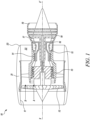
- Figure 1 shows a ducted gas turbine engine 10 having a principal rotational axis X-X'.
- the gas turbine engine 10 includes, in axial flow series, an air intake 11, a propulsive fan 12, an intermediate pressure compressor 13, a high pressure compressor 14, combustion equipment 15, a high pressure turbine 16, an intermediate pressure turbine 17, a low pressure turbine 18, and a core engine exhaust nozzle 19.
- a nacelle 21 generally surrounds the gas turbine engine 10 and defines the air intake 11, a bypass duct 22 and a bypass exhaust nozzle 23.
- air entering the air intake 11 is accelerated by the propulsive fan 12 to produce two air flows: a first air flow A into the intermediate pressure compressor 13 and a second air flow B which passes through the bypass duct 22 to provide propulsive thrust.
- the intermediate pressure compressor 13 compresses the first air flow A directed into it before delivering that air to the high pressure compressor 14 where further compression takes place.
- the compressed air exhausted from the high pressure compressor 14 is directed into the combustion equipment 15 where it is mixed with fuel and the mixture is combusted.
- the resultant hot combustion products then expand through, and thereby drive the high, intermediate and low pressure turbines 16, 17, 18 before being exhausted through the core engine exhaust nozzle 19 to provide additional propulsive thrust.
- the high, intermediate and low pressure turbines 16, 17, 18 respectively drive the high and intermediate pressure compressors 14, 13 and the propulsive fan 12 by suitable interconnecting shafts.
- the gas turbine engine 10 is used in an aircraft. In some embodiments, the gas turbine engine 10 is an ultra-high bypass ratio engine (UHBPR).
- UHBPR ultra-high bypass ratio engine
- present invention is equally applicable to aero gas turbine engines, marine gas turbine engines, and land-based gas turbine engines.
- Figure 2 illustrates a schematic sectional side view of a coated article 100.
- the gas turbine engine 10 shown in Figure 1
- the coated article 100 includes a substrate 102 including a surface 104.
- the coated article 100 further includes a protective coating 106.
- the protective coating 106 is disposed on the surface 104 of the substrate 102.
- the protective coating 106 is positioned to define an external surface of the substrate 102, such that the protective coating 106 is directly exposed to extreme temperature conditions (e.g., hot gas flow path), and may improve oxidation and corrosion resistance of the substrate 102.
- the protective coating 106 may have, in certain embodiments, a thickness from about 20 microns ( ⁇ m) to about 300 ⁇ m.
- the protective coating 106 may have a coefficient of thermal expansion (CTE) that closely matches that of the substrate 102 and may exhibit limited mechanical property interactions with a material of the substrate 102 over an extended period of time at elevated temperatures. Furthermore, the protective coating 106 may be capable of being metallurgically bonded to the material of the substrate 102 to be highly resistant to spalling.
- CTE coefficient of thermal expansion
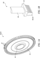
- FIG 3A illustrates a schematic perspective view of a turbine disc 110 of the gas turbine engine 10 (shown in Figure 1 ).
- the turbine disc 110 may be, e.g., a disc of the high pressure turbine 16, the intermediate pressure turbine 17 or the low pressure turbine 18 shown in Figure 1 .
- the coated article 100 is the turbine disc 110.
- the turbine disc 110 includes a hub 112 arranged along the primary rotational axis X-X' (shown in Figure 1 ) of the gas turbine engine 10 (shown in Figure 1 ).
- the turbine disc 110 further includes a bore through which a shaft (not shown) may extend.
- the turbine disc 110 further includes slots 114 arranged along an outer periphery of the turbine disc 110 into which turbine blades (not shown) may be inserted.
- a web section 116 of the turbine disc 110 extends between the outer periphery, where the slots 114 are located, and the hub 112.
- the protective coating 106 may be disposed on the web section 116 of the turbine disc 110 and/or the slots 114, which are is directly exposed to extreme temperatures.
- the protective coating 106 may be utilized anywhere on the turbine disc 110 and the substrate 102 (shown in Figure 2 ) may be any portion of the turbine disc 110.
- FIG 3B illustrates a schematic perspective view of a blade 120 of the gas turbine engine 10 (shown in Figure 1 ).
- the blade 120 includes a blade root 122, a platform 124 coupled to the blade root 122, and an aerofoil 126 coupled to the platform 124.
- the blade root 122, the platform 124 and the aerofoil 126 may be a single piece construction or may be separate components joined together.
- the platform 124 may be sandwiched between the blade root 122 and the aerofoil 126 and may separate the blade root 122 from the aerofoil 126 such that gasses passing over the aerofoil 126 may be blocked from moving down towards the blade root 122.
- the aerofoil 126 may be shaped aerodynamically to interact with gases moving over the blade 120.
- the blade root 122 may be arranged to couple the blade 120 with a disc (e.g., the turbine disc 110 shown in Figure 3A ).
- the coated article 100 is the blade root 122 the blade 120.
- the protective coating 106 may be disposed on the blade root 122 of the blade 120 under the platform 124 that enables the blade 120 to operate at high temperatures.
- a protective coating e.g., the protective coating 106
- a substrate e.g., the turbine disc 110 or the blade root 1202.
- the methods and processes described hereinafter are not limited to this use and application only, and those methods and processes are described by way of an example for forming the protective coating on the substrate using the described methods and processes.
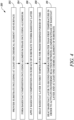
- Figure 4 is a flow chart illustrating a method 200 of forming a protective coating.
- the protective coating may be similar to the protective coating 106 described with reference to Figure 2 .
- the method 200 will be described hereinafter with reference to the coated article 100 of Figure 2 and Figures 4-8 .
- Figure 5 illustrates a schematic sectional view of the substrate 102, according to an embodiment of the present invention.
- the method 200 includes providing the substrate 102 including at least one chemical element 130 and the surface 104.
- the at least one chemical element 130 is nickel. It should be understood that nickel is described hereinafter as the at least one chemical element 130 by way of example only, and the at least one chemical element 130 may be any element based on application requirements.
- Suitable alloys for the substrate 102 may include, but are not limited to, nickel-based superalloys, cobalt-based superalloys, iron-based superalloys, low sulphur nickel-based superalloys, low sulphur cobalt-based superalloys, low sulphur iron-based superalloys, etc.
- Such superalloys may typically include a polycrystalline structure, but may have portions with a single-crystal or directionally solidified crystalline structure.
- the substrate 102 may include nickel-based superalloys commercially available under the trademark Inconel ® .
- the method 200 further includes forming a basecoat composition 140 (shown in Figure 6D ) including an aluminium phase 142 (shown in Figure 6D ) including aluminium.
- Figures 6A-6D illustrate steps of forming the basecoat composition 140 (shown in Figure 6D ). Specifically, formation of the basecoat composition 140 will be described with reference to Figures 6A-6D .
- forming the basecoat composition 140 at step 204 further includes forming a solution 144 including phosphoric acid (H 3 PO 4 ).
- the solution 144 maybe formed by diluting a required mass of phosphoric acid, e.g., with water.
- forming the basecoat composition 140 at step 204 further includes adding aluminium hydroxide (Al(OH) 3 ) 141 to the solution 144.
- aluminium hydroxide Al(OH) 3
- a ratio of a weight of phosphoric acid to a weight of aluminium hydroxide is about 3:1.
- the ratio of the weight of phosphoric acid to the weight of aluminium hydroxide may vary from about 1:1 to about 23:1, preferably 3:1.
- forming the basecoat composition 140 (shown in Figure 6D ) at step 204 further includes adding the aluminium phase 142 to the solution 144.
- the aluminium phase 142 may be added to the solution 144 in the form of powder or particulates.
- the aluminium phase 142 of the basecoat composition 140 (shown in Figure 6D ) includes at least one of pure aluminium, an aluminium-chromium alloy, an aluminium-niobium alloy, an aluminium-tantalum-alloy, an aluminium-manganese alloy, an aluminium-silicon alloy, an intermetallic aluminium alloy, and an aluminium alloy comprising at least 50% aluminium.
- the aluminium phase 142 may be a high entropy mix of aluminium, niobium, tantalum, chromium and manganese.
- the basecoat composition 140 may further include at least one of yttrium, zirconium, hafnium and silicon.
- the aluminium phase 142 may contain a minor addition of other elements, including, but not limited to, yttrium, zirconium, hafnium and/or silicon as active elements.
- Such alloying elements may improve oxidation resistance of the aluminium phase 142 in the basecoat composition 140 (shown in Figure 6D ) during intermediate stages of formation of the protective coating 106 (shown in Figure 2 ).
- silicon and other allowing elements may be added to the aluminium phase 142 as an aluminium alloy or separately.
- Other optional additions including, but not limited to, lanthanum, cerium, magnesium, and other rare earth or reactive metals, may also be added to obtain enhanced environmental resistance.
- the aluminium phase 142 may be added to the solution 144 as an aluminium eutectic.
- aluminium eutectics are low melting mixtures of aluminium and other alloying elements desirable for further processing.
- the method 200 further includes treating the aluminium phase 142 with a halide-based wash coat solution 146 or a mixed blend of halide-based salts prior to adding the aluminium phase 142 to the solution 144.
- treating the aluminium phase 142 with the halide-based wash coat solution 146 may encourage vapour phase transport of aluminium, chromium, silicon, titanium, tantalum, niobium, manganese and other alloying elements to the surface 104 (shown in Figure 2 ) during further processing.
- the halide-based wash coat solution 146 includes at least one of nickel chloride, ammonium chloride, and cobalt chloride.
- forming the basecoat composition 140 at step 204 further includes stirring the solution 144 (shown in Figure 6C ) to obtain the basecoat composition 140 including aluminium hydrogen phosphate (i.e., a binder phase 148) and the aluminium phase 142.
- stirring the solution 144 leads to a chemical reaction between phosphoric acid and aluminium hydroxide leading to the formation of aluminium hydrogen phosphate.
- the aluminium phase 142 along with the other alloying elements, may remain suspended in aluminium hydrogen phosphate, which may act as a binder for the aluminium phase 142.
- the binder phase 148 may be capable of carrying and protecting the aluminium phase 142 as the basecoat composition 140 is further processed.
- the basecoat composition 140 includes, in weight percent, at least about 50% aluminium. In some embodiments, the basecoat composition 140 includes, in weight percent, at least about 55%, at least about 60%, at least about 65%, at least about 70% or at least about 75% aluminium. It should be understood that the aluminium phase 142 is schematically shown dispersed in the binder phase 148 for illustrative purposes.
- the binder phase 148 may include other salts instead of aluminium hydrogen phosphate (a phosphate salt), e.g., a chromate salt, based on application requirements. Specifically, in some embodiments, the binder phase 148 includes at least one of a phosphate salt and a chromate salt. Desired composition of the binder phase 148 may be obtained by appropriately choosing the initial reaction elements.
- Figure 7 illustrates a schematic sectional side view of the substrate 102 and a basecoat layer 150.
- the method 200 further includes applying the basecoat composition 140 (shown in Figure 6D ) on the surface 104 of the substrate 102 to form the basecoat layer 150.
- the basecoat composition 140 may be applied on the surface 104 of the substrate 102 using any known method, e.g., brush application, solvent spray deposition, electrostatic spray deposition, dip coating, etc. Such methods may be cheap and efficient as well.
- the surface 104 may be pre-treated mechanically, chemically, or both to prepare the surface 104 for reception of the basecoat composition 140 (shown in Figure 6D ).
- Suitable pretreatment methods may include grit blasting, micromachining, laser etching, treatment with chemical etchants, treatment with pressurized water, and the like, as well as combinations of the one or more aforementioned methods.
- the basecoat layer 150 includes the binder phase 148 that may include hydrated aluminium hydrogen phosphate (a phosphate salt).
- the aluminium phase 142 is dispersed in the binder phase 148 as shown schematically in Figure 7 .
- the binder phase 148 may support and protect aluminium and other alloying elements present in the aluminium phase 142 such that the basecoat composition 140 (shown in Figure 6D ) may be easily applied on the surface 104 of the substrate 102 in factory environments.
- a thickness of the protective coating 106 may be controlled over a wide range, from about 20 ⁇ m to about 300 ⁇ m, according to application requirements.
- the thickness of the protective coating 106 may be controlled by controlling the thickness of the basecoat layer 150.
- thinner coatings, below 50 ⁇ m may be obtained by depositing the basecoat layer 150 by an aerosol spray technique, while thicker coatings may be obtained by depositing the basecoat layer 150 by brush coating or dip coating methods.
- Figure 8 illustrates a schematic sectional side view of the substrate 102 and the basecoat layer 150.
- the method 200 further includes heating the basecoat layer 150 to a first temperature T1 for a predetermined period of time.
- the first temperature T1 is about 250 degrees Celsius (°C).
- the predetermined period of time may be, for example, about 12 hours, however, the predetermined period of time may depend upon factors, such as the composition of the basecoat layer 150.
- the basecoat layer 150 may be heated to cure the basecoat layer 150 and provide environmental protection to the aluminium phase 142 dispersed in the binder phase 148 of the basecoat layer 150 during handling and subsequent processing.
- the ratio (i.e., 3:1) of the weight of phosphoric acid to the weight of aluminium hydroxide in the solution 144 may enable, after heating, formation of the basecoat layer 150 that is hard and difficult to damage, enabling optimum mechanical protection against handling damage. Additionally, this ratio of the weight of phosphoric acid to the weight of aluminium hydroxide in the solution 144 (shown in Figure 6B ) may retain any particulates (i.e., the alloying elements), suspended in the solution 144 (shown in Figure 6C ), significantly longer than other ratios, thereby improving reproducibility and consistency of formation of the protective coating 106 (shown in Figure 2 ).
- Figure 9 illustrates a schematic sectional side view of the substrate 102 and the basecoat layer 150.
- the method 200 further includes heating the basecoat layer 150 to a second temperature T2 greater than the first temperature T1 in order to activate an exothermic reaction between at least the aluminium phase 142 of the basecoat layer 150 and the at least one chemical element 130 of the substrate 102.
- heating the basecoat layer 150 provides the activation energy for the exothermic chemical reaction between at least a portion of the aluminium phase 142 present in the basecoat layer 150 adjacent to the surface 104 of the substrate 102 and the at least one chemical element 130 of the substrate 102.
- the aluminium phase 142 of the basecoat layer 150 may interdiffuse with the substrate 102, thereby forming the protective coating 106 (shown in Figure 2 ) on the surface 104 of the substrate 102.
- the exothermic reaction may take place in air or in a controlled environment.
- the second temperature T2 is less than or equal to 900 degrees Celsius. Such temperatures may be utilized for forming the protective coating 106 (shown in Figure 2 ) on the blade root 122 of the blade 120 below the platform 124 (shown in Figure 3B ). Selecting such values of the second temperature T2 may allow formation of the protective coating 106 (shown in Figure 2 ) without significant change in mechanical properties of the blade root 122 (shown in Figure 3B ).
- the second temperature T2 is from about 750 degrees Celsius to about 850 degrees Celsius. Such temperatures may be utilized for forming the protective coating 106 (shown in Figure 2 ) on surfaces of the turbine disc 110 (shown in Figure 3A ).
- Heating the basecoat layer 150 to the second temperature T2 may provide the initial energy to activate the exothermic reaction that leads to formation of the protective coating 106 (shown in Figure 2 ).
- the at least one chemical element 130 may be nickel as described earlier.
- the exothermic reaction between at least the aluminium phase 142 of the basecoat layer 150 and nickel produces nickel aluminide.
- the exothermic reaction may be activated at the second temperature T2 of about 650 degrees Celsius, a self-propagating exothermic reaction may be achieved at the second temperature T2 of about 800 degrees Celsius. Such an exothermic reaction may lead to a formation of a nickel aluminide coating with desirable thickness.
- the exothermic reaction may be enhanced by treatment of the aluminium phase 142 with the halide-based wash coat solution 146 (Shown in Figure 6C ). This may allow transport of aluminium present in the aluminium phase 142 towards the surface 104 of the substrate 102 for exothermic reaction with the at least one chemical element 130 (e.g., nickel).
- the halide-based wash coat solution 146 may include nickel chloride. Since the substrate 102 already contains nickel as the at least one chemical element 130, treatment of aluminium phase 142 with the halide-based wash coat solution 146 may not lead to addition of any other element to the final coating. Further, in this example, chlorine may facilitate the transport of aluminium towards the surface 104 of the substrate 102, and may be eliminated during heating of the basecoat layer 150 to the second temperature T2.
- use of eutectic aluminium alloy powders may allow the exothermic reaction to be customised based on application requirements, by either lowering the aluminium alloy melting point, adding alloy elements that increase hot corrosion resistance, and/or adding alloy elements that increase the exothermic energy release.
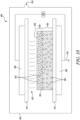
- FIG 10 illustrates a schematic view of an apparatus 160 for applying glow discharge plasma 162 on the basecoat layer 150.
- heating the basecoat layer 150 to the second temperature T2 at step 210 further includes applying the glow discharge plasma 162 on the basecoat layer 150.
- Application of the glow discharge plasma 162 on the basecoat layer 150 involves exposing the basecoat layer 150 to ionising radiation produced by the glow discharge plasma 162. The ion bombardment then activates the exothermic reaction between the aluminium phase 142 of the basecoat layer 150 and the at least one chemical element 130 of the substrate 102 present at the surface 104, thereby forming the protective coating 106 (shown in Figure 2 ) in situ.
- a plasma torch may be utilized for heating the basecoat layer 150 to the second temperature T2.
- Localized application of the glow discharge plasma 162 on the basecoat layer 150 may allow formation of the protective coating 106 (shown in Figure 2 ) without the need to heat up the bulk of the substrate 102 (e.g., the turbine disc 110 shown in Figure 3A ), saving both time (as heating up the bulk may need a significant period of time, as well as the time to cool from the heat-treatment temperature) and energy (as a significant thermal energy input is needed to heat the entire bulk of the substrate 102 to the required process temperature and to maintain that temperature). Further, a mass of the substrate 102 may be used as a heat sink to remove thermal energy from the surface 104 of the substrate 102 during the exothermic reaction and post formation of the protective coating 106 (shown in Figure 2 ).
- the basecoat layer 150 may be heated up to 800 degrees Celsius.
- the second temperature T2 is less than or equal to 800 degrees Celsius.
- Such temperatures may be beneficial for forming the protective coating 106 (shown in Figure 2 ) on surfaces of the turbine disc 110 (shown in Figure 3A ) since application of heat may not lead to any significant change in mechanical properties of a material that the turbine disc 110 (shown in Figure 3A ) is typically made of (e.g., a nickel-based superalloy).
- temperatures below 800 degrees Celsius may prevent over-aging of an alloy microstructure of the turbine disc 110 (shown in Figure 3A ).
- the apparatus 160 includes a control chamber 164 that can be pumped down to a soft vacuum using a vacuum pump (not shown).
- the apparatus 160 further includes a first electrode 166 for mounting the substrate 102 along with the basecoat layer 150 to be treated.
- the first electrode 166 and the second electrode 168 are opposingly arranged.
- the second electrode 168 is spaced apart from the substrate 102 and the basecoat layer 150.
- a first dielectric 172 is coupled to the first electrode 166 and a second dielectric 174 is coupled to the second electrode 168.
- the substrate 102 is mounted on the first dielectric 172. It should be understood that either or both the first and second electrodes 166, 168 may be covered by a respective dielectric.
- the first and second dielectrics 172, 174 may include a material such as Poly-ethylene Terephtalate (PET), Poly-ethylene Naphtalate (PEN), Polytetrafluoroethylene (PTFE), or a ceramic such as silica or alumina. Any combination or mixture of the aforementioned materials may be used as well.
- PET Poly-ethylene Terephtalate
- PEN Poly-ethylene Naphtalate
- PTFE Polytetrafluoroethylene
- ceramic such as silica or alumina. Any combination or mixture of the aforementioned materials may be used as well.
- the glow discharge plasma 162 is generated using a pulsed direct current (DC) power supply 176.
- the second electrode 168 is connected to one end of the pulsed DC power supply 176 and the first electrode 166 is coupled to the other end of the pulsed DC power supply 176 as well as to ground 178.
- control chamber 164 is supplied with a flow of plasma gas through an inlet 170. Air in the control chamber 164 may be replaced with the plasma gas.
- the plasma gas may be an inert gas such as argon.
- the plasma gas may be any other gas, e.g., nitrogen, oxygen, carbon dioxide, Helium, NH 3 , etc., or any combination or mixture of these gasses.
- the first and second electrodes 166, 168 are energized using the pulsed DC power supply 176.
- the glow discharge plasma 162 may be generated between the second dielectric 174 and the basecoat layer 150 of the substrate 102. This may heat the basecoat layer 150 disposed on the surface 104 of the substrate 102.
- voltage may not be applied to the first and second electrodes 166, 168 to initiate generation of the glow discharge plasma 162 until a pressure inside the control chamber 164 is sufficiently low such that a gas molecule density inside the control chamber 164 may be low enough to maintain the glow discharge plasma 162 essentially in an "abnormal glow" state within the control chamber 164.
- "abnormal glow” occurs when essentially all gas molecules inside the control chamber 164 may be ionized to act as carriers for current.
- the pressure inside the control chamber 164 may be maintained between 100 millitorrs (mTorr) and 1,500 mTorr when establishing the "abnormal glow" state of the glow discharge plasma 162, by controlling flow of the plasma gas into the control chamber 164.
- the apparatus 160 may further include one or more mass flow controllers (not shown) which may be operated individually or in combination to provide a wide range of operating pressures within the control chamber 164.
- a pressure gauge (not shown) may also be provided to continuously monitor and control pressure inside the control chamber 164.
- the glow discharge plasma 162 may be maintained using a DC, pulsed DC, or radio frequency (RF) power supplies.
- the pulsed DC power supply 176 is preferred, providing more control over the "abnormal glow" state of the glow discharge plasma 162, while allowing simplification of the electrode system since it may not be necessary to impedance match the substrate electrode (i.e., the first electrode 166) as would be required when using RF power supply.
- the glow discharge plasma 162 generated using the pulsed DC power supply 176 may be more stable, thereby mitigating plasma breakdown and arcing.
- a frequency of the pulsed DC power supply 176 may be varied up to 350 kilohertz (kHz), with a preferred range of about 150-350 kHz. At frequencies above this range, the apparatus 160 may become unstable and the glow discharge plasma 162 may start to arc. Surface temperatures in excess of 700 degrees Celsius may be achieved to heat the basecoat layer 150 using the pulsed DC power supply 176.
- Figure 11 illustrates a schematic detailed sectional view of the coated article 100.
- the protective coating 106 e.g., nickel aluminide
- the protective coating 106 may be a multi-phase coating, formed by dissolution of the alloying elements, rather than diffusion, as a result of the exothermic reaction. This may be evident from a planar melt front of the protective coating 106 forming a demarcation with the substrate 102.
- the protective coating 106 is formed in layers as the exothermic reaction proceeds.
- energy from the glow discharge plasma 162 may trigger a local, very energetic exothermic reaction giving rise to a plurality of projections 180 (i.e., peak asperities) formed during the exothermic reaction.
- the plurality of projections 180 extend from a major surface 182 of the protective coating 106.
- chemical energy released from the exothermic reaction may lead to local melting of the alloying elements present in the aluminium phase 142 of the basecoat layer 150, lateral wetting of the surface 104 of the substrate 102, and release of further energy by the exothermic reaction, propagating formation of the protective coating 106.
- the exothermic reaction stops.
- the plurality of projections 180 may include nickel aluminide as well as other alloying elements present in the aluminium phase 142.
- the method 200 further includes removing the plurality of projections 180 extending from the major surface 182 of the protective coating 106.
- the plurality of projections 180 may be brittle, may crack, and may be removed as part of subsequent component manufacture (e.g., machining, surface cleaning, etc).
- a dense, multi-phase, aluminium-rich protective coating 106 is obtained that may resist oxidation and hot corrosion at temperatures up to 800 degrees Celsius.
- the protective coating 106 may also function at higher temperatures, provided a material of the substrate 102 is designed to operate at such increased temperatures.
- the method 200 further includes eliminating the binder phase 148 (shown in Figures 7-9 ) from the protective coating 106.
- the presence of certain elements (e.g., phosphorous) in the chemical composition of the binder phase 148 may lead to formation of low melting point eutectics, e.g., with sodium sulphate (Na 2 SO 4 ) typically present in environment.
- Na 2 SO 4 sodium sulphate
- the binder phase 148 (shown in Figures 7-9 ) may be removed through surface finishing techniques.
- Figure 12 illustrates a schematic sectional view of the coated article 100.
- the thermally activated, intermetallic protective coating 106 segregates into five different elemental rich zones during formation of the protective coating 106, as a result of progression of the exothermic reaction front between the aluminium phase 142 (shown in Figure 10 ) and the substrate 102 (e.g., a nickel-based superalloy, such as Inconel ® ). Aluminium content of the protective coating 106 decreases from an outer surface 107 of the protective coating 106 to the surface 104 of the substrate 102.
- the protective coating 106 includes a layer 184 disposed adjacent to the substrate 102.
- the layer 184 may be regarded as a first layer of the protective coating 106 next to the surface 104 of the substrate 102.
- the layer 184 may include an aluminium rich nickel aluminide, but with chromium, cobalt and titanium, along with other elements of the substrate 102 all present but in small quantities.
- the protective coating 106 further includes a layer 186 disposed adjacent to the layer 184 and away from the surface 104 of the substrate 102.
- the layer 186 may be regarded as a second layer of the protective coating 106.
- the layer 186 may be a narrow band that is enriched with cobalt, aluminium, and titanium, but depleted in nickel and chromium.
- the protective coating 106 further includes a layer 188 disposed adjacent to the layer 186 and away from the surface 104 of the substrate 102.
- the layer 188 may be regarded as a third layer of the protective coating 106.
- the layer 188 may be a zone similar to the layer 184 but containing a lower chromium content.
- the protective coating 106 further includes a layer 190 disposed adjacent to the layer 188 and away from the surface 104 of the substrate 102.
- the layer 190 may be regarded as a fourth layer of the protective coating 106.
- the layer 190 may be a narrow band that is enriched in aluminium, chromium, molybdenum, and titanium, but depleted in nickel.
- the protective coating 106 further includes a layer 192 disposed adjacent to the layer 190 and away from the surface 104 of the substrate 102.
- the layer 192 may be regarded as a fifth layer of the protective coating 106.
- the layer 192 may be similar to the layer 184, but further enriched in aluminium, with a lower cobalt content.
- the layer 192 may include asperity peaks associated with early exothermic reaction between the aluminium phase 142 (shown in Figure 10 ) and the substrate 102.
- the layer 192 may include the outer surface 107 of the protective coating 106.
- the narrow bands enriched with chromium, molybdenum, and titanium may be caused by separation of low solubility alloying elements from the intermetallic phase of the protective coating 106 during cooling.
- the protective coating 106 includes, in weight percent, at least 70.35% of aluminium, at least 16.11% of nickel, at least 5.68% of cobalt, at least 5.22% of chromium, at least 1.36% of titanium, at least 0.94% of molybdenum, at least 0.2% of tantalum, at least 0.05% of hafnium, at least 0.05% of boron, at least 0.03% carbon, and at least 0.01% of zirconium.
- a final composition the protective coating 106 may depend upon a composition of the substrate 102 and the alloying elements added to the aluminium phase 142 as the protective coating 106 is formed by dissolution of the surface 104 of the substrate 102 into a heat activated melt zone.
- the disclosed method 200 restricts the process of forming the protective coating 106 to the second temperature T2 ensuring that optimum mechanical properties of the substrate 102 are preserved during formation of the protective coating 106. Further, the aluminium phase 142 of the basecoat composition 140 may interdiffuse with the substrate 102 when the basecoat layer 150 is heated to the second temperature T2, thereby forming the protective coating 106 on the substrate 102.
- the method 200 is based on developing the basecoat composition 140 (e.g., a slurry) which may be sprayed, painted or otherwise applied, cheaply and efficiently on the surface 104 of the substrate 102.
- the basecoat composition 140 may support reactive elements (i.e., the aluminium phase 142) during application of the basecoat composition 140 on the surface 104 of the substrate 102, whilst providing environmental protection to the reactive elements during part handling and subsequent heat treatment.
- heating the basecoat layer 150 to the first temperature T1 may cure the basecoat layer 150, thereby providing environmental protection to the aluminium phase 142 of the basecoat composition 140.
- the proposed method 200 is robust, but simple, and may be easily implemented in factory environments.
- a basecoat composition was first prepared.
- the basecoat composition did not form part of the final protective coating.
- the basecoat composition was capable of carrying and protecting active ingredients while the binder composition along with the active ingredients were processed by a plasma treatment.
- the basecoat composition For forming the basecoat composition, a required mass of phosphoric acid was diluted to form a solution. Aluminium hydroxide was then added to this solution to obtain an aluminium phosphate binder solution where a ratio of a weight of phosphoric acid to a weight of aluminium hydroxide is 3:1. Aluminium, and other desired alloying elements were added to this solution as aluminium eutectics in a concentration of 2.5 grams (g) of aluminium/aluminium alloy (325 mesh) added to 5 g of the aluminium phosphate binder solution dissolved in water (1 part aluminium phosphate binder to 15 parts of de-ionised water, by weight). The solution was then stirred at about 150 degrees Celsius for about 30 minutes. The final slurry was obtained as the basecoat composition.
- aluminium/aluminium alloy 325 mesh
- a diluted basecoat composition was then pipetted onto the surface of the substrate to obtain a basecoat layer.
- the basecoat layer was then dried in air at about 250 degrees Celsius for about 12 hours.
- the basecoat layer comprised of hydrated aluminium hydrogen phosphates and aluminium, along with various alloying elements.
- the basecoat layer was then heated to temperatures up to 800 degrees Celsius for about 4 hours, which converted hydrated aluminium hydrogen phosphates to aluminium phosphate, by losing water vapour. Heat treatment triggered an exothermic reaction between aluminium (along with other alloying elements) and the substrate that produced a thick nickel-aluminide based complex alloy coating.
- Heating treatment was performed through application of glow discharge plasma on the basecoat layer in argon gas atmosphere for about 4 hours.
- the glow discharge plasma was triggered using a pulsed DC power supply, output 5 kilowatts (kW), at a pulsed DC voltage from about 200 volts (V) to about 650 V, and a maximum frequency of 350 kHz, with a 15 milliseconds (ms) on-time.
- the optimum frequency was 250 kHz with a 15 ms on-time.
- the final protective coating was produced at 650 V, a current density of 9.25 milliamperes per square centimetre (mA/cm 2 ), and a power density of 6 W/cm 2 .
- surface temperature measured was about 710 degrees Celsius. Further, the aforementioned parameters consistently produced a thin coating with a thickness of about 30-50 ⁇ m.
- Figure 13 illustrates an exemplary graph 300 showing curves 302, 304 of power versus substrate temperature for air and argon gas, respectively.
- air as the plasma gas may not allow the required power density / current density to activate the exothermic reaction.
- temperatures greater than 320 degrees Celsius were not reached with air as the plasma gas before plasma breakdown. Air was prone to breaking down when high voltages were applied, and therefore, the preferred plasma gas was argon, although any other heavy inert gas may also be utilized. Surface temperatures in excess of 700 degrees Celsius were achieved to heat the basecoat layer using the pulsed DC power supply.
- Figure 14 illustrates an exemplary graph 310 showing curves 312, 314, 316 of ion current versus plasma voltage corresponding to three different chamber pressure conditions 187 mTorr / 10 standard cubic centimetres per minute (sccm), 860 mTorr / 198 sccm, and 1271 mTorr / 300 sccm, respectively, of a glow discharge plasma apparatus.
- Available operating power density was dependent on the induced plasma voltage and ion current density that results. Controlling chamber pressure was critical to obtaining a stable operating condition, and thus, the power density, which in turn may control the induced surface temperature at the basecoat layer.
- the chamber pressure range was maintained between 100 mTorr and 1500 mTorr to adjust the power density of glow discharge plasma, the ion current density, and the plasma voltage.
- the preferred operating pressure was 225 mTorr and 198 sccm. This operating point may be obtained with the plasma voltage of 350 V and the ion current density of 8.5 mA/cm 2 , thereby achieving the power density of 3 W/cm 2 .
- Such conditions were sufficient to develop the glow discharge plasma that was stable and supplied enough energy (i.e., current density) to enable or activate the exothermic reaction.
- Figure 15 illustrates an exemplary graph 320 showing a curve 322 of surface temperature versus ion current. Plotting the ion current against the surface temperature, under a given set of operating conditions, provided a linear relationship, which allowed the ion current density to be calibrated against the surface temperature. This was dependent on a component surface area, the chamber pressure, and the plasma voltage induced. These plasma conditions were modelled, and the graph 320 demonstrates that the surface temperatures above 700 degrees Celsius were achieved for certain ion current values, whilst a bulk of the substrate remained unaffected from heat due to a heat capacity of the substrate restricting a rate of rise of the temperature of the substrate.
- the preferred parameters were current density of about 8.5 mA/cm 2 , nominal pressure of about 225 mTorr, voltage of about 350 V, and pulse DC frequency of about 250 kHz with 1.6 ⁇ s on-time.
- the present invention refers to a turbine disc and a blade of a gas turbine engine, the present invention is equally applicable to a turbine shroud, an abradable seal, a combustion chamber wall, or a combustion chamber tile.
- the present invention has been described with reference to a metallic, superalloy, article for a gas turbine engine, the present invention is equally applicable to a metallic, superalloy, article for aero gas turbine engines, marine gas turbine engines, automotive gas turbine engines, or industrial gas turbine engines.
- the present invention is equally applicable to metallic, superalloy, articles for other turbomachines, e.g., steam turbines or other apparatus requiring metallic, superalloy, articles with thermal barrier coatings.
Landscapes
- Chemical & Material Sciences (AREA)
- Materials Engineering (AREA)
- Organic Chemistry (AREA)
- Engineering & Computer Science (AREA)
- Metallurgy (AREA)
- Mechanical Engineering (AREA)
- Chemical Kinetics & Catalysis (AREA)
- General Chemical & Material Sciences (AREA)
- Inorganic Chemistry (AREA)
- Life Sciences & Earth Sciences (AREA)
- Wood Science & Technology (AREA)
- Coating By Spraying Or Casting (AREA)
- Turbine Rotor Nozzle Sealing (AREA)
Abstract
Description
- The present invention relates to a protective coating, a coated article, and a method of forming the protective coating.
- Existing corrosion protective coatings for gas turbine engine components (e.g., turbine discs) are aimed at protection against low temperature hot corrosion. Such corrosion protective coatings are formed using traditional methods, such as chemical vapour deposition (CVD), electroplating, deposition of a reactive metal (e.g., aluminium) within a binder material (e.g., a phosphate), and thermal/plasma spray methods that permit deposition of a corrosion resistant alloy onto a surface of the components.
- Most current coating processes require processing at high temperatures, typically above 900°C, or a subsequent heat-treatment of the coating above such temperatures as part of the coating process. For certain components of gas turbine engines (e.g., turbine discs), it is critical that the temperatures involved in the coating process should be kept below certain temperatures (e.g., 900 °C) to preserve optimum mechanical properties of materials of those components.
- According to a first aspect there is provided a method of forming a protective coating. The method includes providing a substrate including at least one chemical element and a surface. The method further includes forming a basecoat composition including an aluminium phase including aluminium. The method further includes applying the basecoat composition on the surface of the substrate to form a basecoat layer. The method further includes heating the basecoat layer to a first temperature for a predetermined period of time. The method further includes applying a glow discharge plasma on the basecoat layer and heating the basecoat layer to a second temperature greater than the first temperature in order to activate an exothermic reaction between at least the aluminium phase of the basecoat layer and the at least one chemical element of the substrate. The exothermic reaction forms the protective coating on the surface of the substrate.
- The disclosed method restricts the process of formation of the protective coating on the surface of the substrate to the second temperature ensuring that optimum mechanical properties of the substrate are preserved. The method is based on developing the basecoat composition (e.g., a slurry) which may be sprayed, painted or otherwise applied, cheaply and efficiently on the surface of the substrate. Further, the basecoat composition may support reactive elements (i.e., the aluminium phase) during application on the surface of the substrate, whilst providing environmental protection to the reactive elements during handling and subsequent heat treatment of the basecoat layer. Specifically, heating the basecoat layer to the first temperature may cure the basecoat layer, thereby providing environmental protection to the aluminium phase of the basecoat composition.
- When the basecoat layer is heated to the second temperature, the aluminium phase of the basecoat composition may interdiffuse with the surface of the substrate forming the protective coating on the substrate. The proposed method is robust, but simple, and may be easily implemented in factory environments.
- In some embodiments, the at least one chemical element is nickel.
- In some embodiments, the exothermic reaction between at least the aluminium phase of the basecoat layer and nickel produces nickel aluminide. Nickel aluminide in the protective coating may provide desirable corrosion resistance to the substrate.
- In some embodiments, the basecoat layer includes a binder phase including at least one of a phosphate salt and a chromate salt. In some embodiments, the aluminium phase is dispersed in the binder phase. The binder phase may be capable of carrying and protecting the aluminium phase dispersed in the binder phase while the basecoat layer is heated to the second temperature.
- In some embodiments, the method further includes eliminating the binder phase from the protective coating. The chemical composition of the binder phase (that includes phosphate) may lead to a formation of low melting point eutectics, e.g., with sodium sulphate typically present in environment. Thus, the binder phase is removed from the protective coating.
- In some embodiments, the method further includes removing a plurality of projections extending from a major surface of the protective coating. In some embodiments, the plurality of projections is formed during the exothermic reaction. The plurality of projections may be removed as part of a surface finishing of the substrate after formation of the protective coating.
- In some embodiments, the basecoat composition comprises, in weight percent, at least about 50% aluminium.
- In some embodiments, forming the basecoat composition further includes forming a solution including phosphoric acid. In some embodiments, forming the basecoat composition further includes adding aluminium hydroxide to the solution. In some embodiments, forming the basecoat composition further includes adding the aluminium phase to the solution. In some embodiments, forming the basecoat composition further includes stirring the solution to obtain the basecoat composition including aluminium hydrogen phosphate and the aluminium phase. The solution may be capable of carrying and protecting the aluminium phase dispersed in the solution for further processing and subsequent heat treatment of the basecoat layer.
- In some embodiments, the method further includes treating the aluminium phase with a halide-based wash coat solution prior to adding the aluminium phase to the solution. Treating the aluminium phase with the halide-based wash coat solution may encourage vapour phase transport of aluminium and other alloying elements associated with the aluminium phase to the surface of the substrate during heating of the basecoat layer. Thus, treating the aluminium phase with the halide-based wash coat solution may enhance the exothermic reaction between the aluminium phase and the at least one chemical element.
- In some embodiments, the halide-based wash coat solution includes at least one of nickel chloride, ammonium chloride, and cobalt chloride. Chlorine present in the halide-based wash coat solution may help transport of aluminium associated with the aluminium phase to the surface of the substrate during heating of the basecoat layer.
- In some embodiments, a ratio of a weight of phosphoric acid to a weight of aluminium hydroxide is about 3:1. Such a ratio of the weight of phosphoric acid to the weight of aluminium hydroxide may produce a hard layer when the basecoat layer is heated to the first temperature. The hard layer may be highly resistant to damage, thereby providing optimum mechanical protection of the aluminium phase against handling damage. Additionally, this ratio may enable any particulates (e.g., alloying elements) suspended in the solution to be held significantly longer than other ratios, thereby improving reproducibility and consistency of formation of the protective coating.
- In some embodiments, the aluminium phase of the basecoat composition includes at least one of pure aluminium, an aluminium-chromium alloy, an aluminium-niobium alloy, an aluminium-tantalum-alloy, an aluminium-manganese alloy, an aluminium-silicon alloy, an intermetallic aluminium alloy, and an aluminium alloy comprising at least 50% aluminium.
- In some embodiments, the basecoat composition further includes at least one of niobium, tantalum, chromium and manganese. Inclusion of such elements may provide desirable properties to the protective coating.
- In some embodiments, the basecoat composition further includes at least one of yttrium, zirconium, hafnium and silicon. Such elements may improve oxidation resistance of the basecoat composition during intermediate stages of the formation of the protective coating.
- Heating the basecoat layer to the second temperature further includes applying a glow discharge plasma on the basecoat layer. Application of the glow discharge plasma on the basecoat layer involves exposing the basecoat layer to ionising radiation produced by the glow discharge plasma. The ion bombardment then triggers the exothermic reaction between the aluminium phase of the basecoat layer and the at least one chemical element of the substrate, thereby forming the protective coating in situ.
- Localized application of the glow discharge plasma on the basecoat layer may allow formation of the protective coating without the need to heat up a bulk of the substrate, saving both time (as heating up the bulk may need a significant period of time, as well as the time to cool from the heat-treatment temperature) and energy (as a significant thermal energy input is needed to heat up the bulk of the substrate to the required heat-treatment temperature and to maintain that temperature). Further, a mass of the substrate may be used as a heat sink to remove thermal energy from the surface of the substrate during the exothermic reaction and post formation of the protective coating.
- In some embodiments, the glow discharge plasma is generated using a pulsed direct current (DC) power supply. Pulsed DC power supply may enable improved control over the glow discharge plasma while allowing simplification of electrodes used for the generation of the glow discharge plasma.
- In some embodiments, the first temperature is about 250 degrees Celsius (°C). Such a temperature may be sufficient to cure the basecoat layer to produce a hard layer that may be difficult to damage, thereby offering optimum mechanical protection of the aluminium phase against handling damage.
- In some embodiments, the second temperature is less than or equal to 900 degrees Celsius. Heating the basecoat layer to the second temperature that is less than or equal to 900 degrees Celsius may allow formation of the protective coating on certain components (e.g., blade root portions of blades) of gas turbine engines where such temperatures may be utilized while preserving the optimum mechanical properties of that component.
- In some embodiments, the second temperature is less than or equal to 800 degrees Celsius. Heating the basecoat layer to the second temperature that is less than or equal to 800 degrees Celsius may activate the exothermic reaction based on the application of the glow discharge plasma for heating the basecoat layer to the second temperature.
- In some embodiments, the second temperature is from about 750 degrees Celsius to about 850 degrees Celsius. Heating the basecoat layer to the second temperature that is from about 750 degrees Celsius to about 850 degrees Celsius may activate the exothermic reaction without using the glow discharge plasma.
- Embodiments will now be described by way of example only, with reference to the Figures, in which:
-
Figure 1 is a schematic sectional view of a gas turbine engine, , according to an embodiment of the present invention; -
Figure 2 is a schematic sectional view of a coated article associated with the gas turbine engine ofFigure 1 , according to an embodiment of the present invention; -
Figure 3A is a schematic perspective view of a turbine disc of the gas turbine engine ofFigure 1 , according to an embodiment of the present invention; -
Figure 3B is a schematic perspective view of a blade of the gas turbine engine ofFigure 1 , according to an embodiment of the present invention; -
Figure 4 is a flow chart illustrating a method of forming a protective coating, according to an embodiment of the present invention; -
Figure 5 is a schematic sectional view of a substrate, according to an embodiment of the present invention; -
Figures 6A-6D illustrate various steps of forming a basecoat composition, according to an embodiment of the present invention; -
Figure 7 is a schematic sectional view of the substrate and a basecoat layer upon application of the basecoat composition on a surface of the substrate, according to an embodiment of the present invention; -
Figure 8 is a schematic sectional view of the substrate and the basecoat layer where the basecoat layer is heated to a first temperature, according to an embodiment of the present invention; -
Figure 9 is a schematic sectional view of the substrate and the basecoat layer where the basecoat layer is heated to a second temperature, according to an embodiment of the present invention; -
Figure 10 is a schematic view of an apparatus for applying glow discharge plasma on the basecoat layer, according to an embodiment of the present invention; -
Figure 11 is a schematic detailed sectional view of the coated article ofFigure 2 , according to another embodiment of the present invention; -
Figure 12 is a schematic sectional view of the coated article ofFigure 2 , according to yet another embodiment of the present invention; -
Figure 13 is an exemplary graph illustrating curves of power versus substrate temperature for air and argon gas, respectively; -
Figure 14 is an exemplary graph illustrating curves of ion current versus plasma voltage corresponding to three different chamber pressure conditions of a glow discharge plasma apparatus; and -
Figure 15 is an exemplary graph illustrating a curve of surface temperature versus ion current. - Aspects and embodiments of the present invention will now be discussed with reference to the accompanying figures. Further aspects and embodiments will be apparent to those skilled in the art.
- As used in, the term "particulate" generally refers to a particle, powder, flake, etc., that inherently exists in a relatively small form, or may be formed by, e.g., grinding, shredding, fragmenting, pulverizing or otherwise, subdividing a larger form of material into a relatively smaller form.
-
Figure 1 shows a ductedgas turbine engine 10 having a principal rotational axis X-X'. Thegas turbine engine 10 includes, in axial flow series, anair intake 11, apropulsive fan 12, anintermediate pressure compressor 13, ahigh pressure compressor 14,combustion equipment 15, ahigh pressure turbine 16, anintermediate pressure turbine 17, alow pressure turbine 18, and a coreengine exhaust nozzle 19. Anacelle 21 generally surrounds thegas turbine engine 10 and defines theair intake 11, a bypass duct 22 and abypass exhaust nozzle 23. - During operation, air entering the
air intake 11 is accelerated by thepropulsive fan 12 to produce two air flows: a first air flow A into theintermediate pressure compressor 13 and a second air flow B which passes through the bypass duct 22 to provide propulsive thrust. Theintermediate pressure compressor 13 compresses the first air flow A directed into it before delivering that air to thehigh pressure compressor 14 where further compression takes place. - The compressed air exhausted from the
high pressure compressor 14 is directed into thecombustion equipment 15 where it is mixed with fuel and the mixture is combusted. The resultant hot combustion products then expand through, and thereby drive the high, intermediate andlow pressure turbines engine exhaust nozzle 19 to provide additional propulsive thrust. The high, intermediate andlow pressure turbines intermediate pressure compressors propulsive fan 12 by suitable interconnecting shafts. - In some embodiments, the
gas turbine engine 10 is used in an aircraft. In some embodiments, thegas turbine engine 10 is an ultra-high bypass ratio engine (UHBPR). - In addition, the present invention is equally applicable to aero gas turbine engines, marine gas turbine engines, and land-based gas turbine engines.
-
Figure 2 illustrates a schematic sectional side view of acoated article 100. In some embodiments, the gas turbine engine 10 (shown inFigure 1 ) includes thecoated article 100. Thecoated article 100 includes asubstrate 102 including asurface 104. In some embodiments, thecoated article 100 further includes aprotective coating 106. Theprotective coating 106 is disposed on thesurface 104 of thesubstrate 102. In some embodiments, theprotective coating 106 is positioned to define an external surface of thesubstrate 102, such that theprotective coating 106 is directly exposed to extreme temperature conditions (e.g., hot gas flow path), and may improve oxidation and corrosion resistance of thesubstrate 102. Theprotective coating 106 may have, in certain embodiments, a thickness from about 20 microns (µm) to about 300 µm. - In some embodiments, the
protective coating 106 may have a coefficient of thermal expansion (CTE) that closely matches that of thesubstrate 102 and may exhibit limited mechanical property interactions with a material of thesubstrate 102 over an extended period of time at elevated temperatures. Furthermore, theprotective coating 106 may be capable of being metallurgically bonded to the material of thesubstrate 102 to be highly resistant to spalling. -
Figure 3A illustrates a schematic perspective view of a turbine disc 110 of the gas turbine engine 10 (shown inFigure 1 ). The turbine disc 110 may be, e.g., a disc of thehigh pressure turbine 16, theintermediate pressure turbine 17 or thelow pressure turbine 18 shown inFigure 1 . In the illustrated embodiment ofFigure 3A , thecoated article 100 is the turbine disc 110. In some embodiments, the turbine disc 110 includes ahub 112 arranged along the primary rotational axis X-X' (shown inFigure 1 ) of the gas turbine engine 10 (shown inFigure 1 ). In some embodiments, the turbine disc 110 further includes a bore through which a shaft (not shown) may extend. - In some embodiments, the turbine disc 110 further includes
slots 114 arranged along an outer periphery of the turbine disc 110 into which turbine blades (not shown) may be inserted. In some embodiments, aweb section 116 of the turbine disc 110 extends between the outer periphery, where theslots 114 are located, and thehub 112. In some embodiments, the protective coating 106 (shown inFigure 2 ) may be disposed on theweb section 116 of the turbine disc 110 and/or theslots 114, which are is directly exposed to extreme temperatures. However, it should be understood that the protective coating 106 (shown inFigure 2 ) may be utilized anywhere on the turbine disc 110 and the substrate 102 (shown inFigure 2 ) may be any portion of the turbine disc 110. -
Figure 3B illustrates a schematic perspective view of ablade 120 of the gas turbine engine 10 (shown inFigure 1 ). Theblade 120 includes a blade root 122, aplatform 124 coupled to the blade root 122, and anaerofoil 126 coupled to theplatform 124. In some embodiments, the blade root 122, theplatform 124 and theaerofoil 126 may be a single piece construction or may be separate components joined together. Theplatform 124 may be sandwiched between the blade root 122 and theaerofoil 126 and may separate the blade root 122 from theaerofoil 126 such that gasses passing over theaerofoil 126 may be blocked from moving down towards the blade root 122. Theaerofoil 126 may be shaped aerodynamically to interact with gases moving over theblade 120. - In some embodiments, the blade root 122 may be arranged to couple the
blade 120 with a disc (e.g., the turbine disc 110 shown inFigure 3A ). In some embodiments, thecoated article 100 is the blade root 122 theblade 120. Specifically, theprotective coating 106 may be disposed on the blade root 122 of theblade 120 under theplatform 124 that enables theblade 120 to operate at high temperatures. - Those skilled in the art will appreciate that the teachings and benefits of an embodiment of the present invention are also applicable to compressor discs and blisk of gas turbine engines, as well as numerous other components that are subjected to stresses at high temperatures, and therefore, require resistance from oxidation and corrosion.
- In the invention, embodiments are described hereinafter in detail for a method of forming a protective coating (e.g., the protective coating 106) on a substrate (e.g., the turbine disc 110 or the blade root 122). A skilled person will appreciate that the methods and processes described hereinafter are not limited to this use and application only, and those methods and processes are described by way of an example for forming the protective coating on the substrate using the described methods and processes.
-
Figure 4 is a flow chart illustrating amethod 200 of forming a protective coating. In some embodiments, the protective coating may be similar to theprotective coating 106 described with reference toFigure 2 . Themethod 200 will be described hereinafter with reference to thecoated article 100 ofFigure 2 andFigures 4-8 . -
Figure 5 illustrates a schematic sectional view of thesubstrate 102, according to an embodiment of the present invention. Referring now toFigures 4 and5 , atstep 202, themethod 200 includes providing thesubstrate 102 including at least onechemical element 130 and thesurface 104. In some embodiments, the at least onechemical element 130 is nickel. It should be understood that nickel is described hereinafter as the at least onechemical element 130 by way of example only, and the at least onechemical element 130 may be any element based on application requirements. - Further, it should be understood that the at least one
chemical element 130 is schematically shown inFigure 5 for descriptive and illustrative purposes. - Suitable alloys for the
substrate 102 may include, but are not limited to, nickel-based superalloys, cobalt-based superalloys, iron-based superalloys, low sulphur nickel-based superalloys, low sulphur cobalt-based superalloys, low sulphur iron-based superalloys, etc. Such superalloys may typically include a polycrystalline structure, but may have portions with a single-crystal or directionally solidified crystalline structure. In some embodiments, thesubstrate 102 may include nickel-based superalloys commercially available under the trademark Inconel®. - Referring now to
Figure 4 , atstep 204, themethod 200 further includes forming a basecoat composition 140 (shown inFigure 6D ) including an aluminium phase 142 (shown inFigure 6D ) including aluminium.Figures 6A-6D illustrate steps of forming the basecoat composition 140 (shown inFigure 6D ). Specifically, formation of thebasecoat composition 140 will be described with reference toFigures 6A-6D . - Referring now to
Figures 4 and6A , forming the basecoat composition 140 (shown inFigure 6D ) atstep 204 further includes forming asolution 144 including phosphoric acid (H3PO4). In some embodiments, thesolution 144 maybe formed by diluting a required mass of phosphoric acid, e.g., with water. - Referring now to
Figures 4 and6B , forming the basecoat composition 140 (shown inFigure 6D ) atstep 204 further includes adding aluminium hydroxide (Al(OH)3) 141 to thesolution 144. In some embodiments, a ratio of a weight of phosphoric acid to a weight of aluminium hydroxide is about 3:1. In some embodiments, the ratio of the weight of phosphoric acid to the weight of aluminium hydroxide may vary from about 1:1 to about 23:1, preferably 3:1. - Referring now to
Figures 4 and6C , forming the basecoat composition 140 (shown inFigure 6D ) atstep 204 further includes adding thealuminium phase 142 to thesolution 144. In some embodiments, thealuminium phase 142 may be added to thesolution 144 in the form of powder or particulates. In some embodiments, thealuminium phase 142 of the basecoat composition 140 (shown inFigure 6D ) includes at least one of pure aluminium, an aluminium-chromium alloy, an aluminium-niobium alloy, an aluminium-tantalum-alloy, an aluminium-manganese alloy, an aluminium-silicon alloy, an intermetallic aluminium alloy, and an aluminium alloy comprising at least 50% aluminium. - Additionally, in some embodiments, other alloying elements may be added to the
aluminium phase 142 such that the final basecoat composition 140 (shown inFigure 6D ) further includes at least one of niobium, tantalum, chromium and manganese. In some embodiments, thealuminium phase 142 may be a high entropy mix of aluminium, niobium, tantalum, chromium and manganese. - Further, in some embodiments, the
basecoat composition 140 may further include at least one of yttrium, zirconium, hafnium and silicon. Specifically, thealuminium phase 142 may contain a minor addition of other elements, including, but not limited to, yttrium, zirconium, hafnium and/or silicon as active elements. Such alloying elements may improve oxidation resistance of thealuminium phase 142 in the basecoat composition 140 (shown inFigure 6D ) during intermediate stages of formation of the protective coating 106 (shown inFigure 2 ). Further, silicon and other allowing elements may be added to thealuminium phase 142 as an aluminium alloy or separately. Other optional additions including, but not limited to, lanthanum, cerium, magnesium, and other rare earth or reactive metals, may also be added to obtain enhanced environmental resistance. - In some embodiments, the
aluminium phase 142 may be added to thesolution 144 as an aluminium eutectic. Generally, aluminium eutectics are low melting mixtures of aluminium and other alloying elements desirable for further processing. - In some embodiments, the
method 200 further includes treating thealuminium phase 142 with a halide-basedwash coat solution 146 or a mixed blend of halide-based salts prior to adding thealuminium phase 142 to thesolution 144. In some embodiments, treating thealuminium phase 142 with the halide-basedwash coat solution 146 may encourage vapour phase transport of aluminium, chromium, silicon, titanium, tantalum, niobium, manganese and other alloying elements to the surface 104 (shown inFigure 2 ) during further processing. In some embodiments, the halide-basedwash coat solution 146 includes at least one of nickel chloride, ammonium chloride, and cobalt chloride. - Referring now to
Figures 4 and6D , forming thebasecoat composition 140 atstep 204 further includes stirring the solution 144 (shown inFigure 6C ) to obtain thebasecoat composition 140 including aluminium hydrogen phosphate (i.e., a binder phase 148) and thealuminium phase 142. In some embodiments, stirring the solution 144 (shown inFigure 6C ) leads to a chemical reaction between phosphoric acid and aluminium hydroxide leading to the formation of aluminium hydrogen phosphate. In some embodiments, thealuminium phase 142, along with the other alloying elements, may remain suspended in aluminium hydrogen phosphate, which may act as a binder for thealuminium phase 142. In some embodiments, thebinder phase 148 may be capable of carrying and protecting thealuminium phase 142 as thebasecoat composition 140 is further processed. - In some embodiments, the
basecoat composition 140 includes, in weight percent, at least about 50% aluminium. In some embodiments, thebasecoat composition 140 includes, in weight percent, at least about 55%, at least about 60%, at least about 65%, at least about 70% or at least about 75% aluminium. It should be understood that thealuminium phase 142 is schematically shown dispersed in thebinder phase 148 for illustrative purposes. - It should be understood that the
binder phase 148 may include other salts instead of aluminium hydrogen phosphate (a phosphate salt), e.g., a chromate salt, based on application requirements. Specifically, in some embodiments, thebinder phase 148 includes at least one of a phosphate salt and a chromate salt. Desired composition of thebinder phase 148 may be obtained by appropriately choosing the initial reaction elements. -
Figure 7 illustrates a schematic sectional side view of thesubstrate 102 and abasecoat layer 150. Referring now toFigures 4 and7 , atstep 206, themethod 200 further includes applying the basecoat composition 140 (shown inFigure 6D ) on thesurface 104 of thesubstrate 102 to form thebasecoat layer 150. In some embodiments, the basecoat composition 140 (shown inFigure 6D ) may be applied on thesurface 104 of thesubstrate 102 using any known method, e.g., brush application, solvent spray deposition, electrostatic spray deposition, dip coating, etc. Such methods may be cheap and efficient as well. - In some embodiments, prior to application of the
basecoat composition 140 on thesurface 104 of thesubstrate 102, thesurface 104 may be pre-treated mechanically, chemically, or both to prepare thesurface 104 for reception of the basecoat composition 140 (shown inFigure 6D ). Suitable pretreatment methods may include grit blasting, micromachining, laser etching, treatment with chemical etchants, treatment with pressurized water, and the like, as well as combinations of the one or more aforementioned methods. - In some embodiments, the
basecoat layer 150 includes thebinder phase 148 that may include hydrated aluminium hydrogen phosphate (a phosphate salt). In some embodiments, thealuminium phase 142 is dispersed in thebinder phase 148 as shown schematically inFigure 7 . Thus, at least a portion of thealuminium phase 142 may be in direct contact with the at least onechemical element 130 of thesubstrate 102 through thesurface 104 of thesubstrate 102. Thebinder phase 148 may support and protect aluminium and other alloying elements present in thealuminium phase 142 such that the basecoat composition 140 (shown inFigure 6D ) may be easily applied on thesurface 104 of thesubstrate 102 in factory environments. - Decreasing a thickness of the
basecoat layer 150 may result in thinner end coatings. In some embodiments, a thickness of the protective coating 106 (shown inFigure 2 ) may be controlled over a wide range, from about 20 µm to about 300 µm, according to application requirements. The thickness of theprotective coating 106 may be controlled by controlling the thickness of thebasecoat layer 150. Typically, thinner coatings, below 50 µm, may be obtained by depositing thebasecoat layer 150 by an aerosol spray technique, while thicker coatings may be obtained by depositing thebasecoat layer 150 by brush coating or dip coating methods. -
Figure 8 illustrates a schematic sectional side view of thesubstrate 102 and thebasecoat layer 150. Referring now toFigures 4 and8 , atstep 208, themethod 200 further includes heating thebasecoat layer 150 to a first temperature T1 for a predetermined period of time. In some embodiments, the first temperature T1 is about 250 degrees Celsius (°C). In some embodiments, the predetermined period of time may be, for example, about 12 hours, however, the predetermined period of time may depend upon factors, such as the composition of thebasecoat layer 150. In some embodiments, thebasecoat layer 150 may be heated to cure thebasecoat layer 150 and provide environmental protection to thealuminium phase 142 dispersed in thebinder phase 148 of thebasecoat layer 150 during handling and subsequent processing. - In some embodiments, the ratio (i.e., 3:1) of the weight of phosphoric acid to the weight of aluminium hydroxide in the solution 144 (shown in
Figure 6B ) may enable, after heating, formation of thebasecoat layer 150 that is hard and difficult to damage, enabling optimum mechanical protection against handling damage. Additionally, this ratio of the weight of phosphoric acid to the weight of aluminium hydroxide in the solution 144 (shown inFigure 6B ) may retain any particulates (i.e., the alloying elements), suspended in the solution 144 (shown inFigure 6C ), significantly longer than other ratios, thereby improving reproducibility and consistency of formation of the protective coating 106 (shown inFigure 2 ). -
Figure 9 illustrates a schematic sectional side view of thesubstrate 102 and thebasecoat layer 150. Referring now toFigures 4 and9 , atstep 210, themethod 200 further includes heating thebasecoat layer 150 to a second temperature T2 greater than the first temperature T1 in order to activate an exothermic reaction between at least thealuminium phase 142 of thebasecoat layer 150 and the at least onechemical element 130 of thesubstrate 102. In other words, heating thebasecoat layer 150 provides the activation energy for the exothermic chemical reaction between at least a portion of thealuminium phase 142 present in thebasecoat layer 150 adjacent to thesurface 104 of thesubstrate 102 and the at least onechemical element 130 of thesubstrate 102. During the exothermic reaction, thealuminium phase 142 of thebasecoat layer 150 may interdiffuse with thesubstrate 102, thereby forming the protective coating 106 (shown inFigure 2 ) on thesurface 104 of thesubstrate 102. In some embodiments, the exothermic reaction may take place in air or in a controlled environment. - In some embodiments, the second temperature T2 is less than or equal to 900 degrees Celsius. Such temperatures may be utilized for forming the protective coating 106 (shown in
Figure 2 ) on the blade root 122 of theblade 120 below the platform 124 (shown inFigure 3B ). Selecting such values of the second temperature T2 may allow formation of the protective coating 106 (shown inFigure 2 ) without significant change in mechanical properties of the blade root 122 (shown inFigure 3B ). - In some embodiments, the second temperature T2 is from about 750 degrees Celsius to about 850 degrees Celsius. Such temperatures may be utilized for forming the protective coating 106 (shown in
Figure 2 ) on surfaces of the turbine disc 110 (shown inFigure 3A ). - Heating the
basecoat layer 150 to the second temperature T2 may provide the initial energy to activate the exothermic reaction that leads to formation of the protective coating 106 (shown inFigure 2 ). As thebasecoat layer 150 is heated, localized reaction occurs between thealuminium phase 142 and the at least onechemical element 130. In some embodiments, the at least onechemical element 130 may be nickel as described earlier. In some embodiments, the exothermic reaction between at least thealuminium phase 142 of thebasecoat layer 150 and nickel produces nickel aluminide. - Although the exothermic reaction may be activated at the second temperature T2 of about 650 degrees Celsius, a self-propagating exothermic reaction may be achieved at the second temperature T2 of about 800 degrees Celsius. Such an exothermic reaction may lead to a formation of a nickel aluminide coating with desirable thickness.
- The exothermic reaction may be enhanced by treatment of the
aluminium phase 142 with the halide-based wash coat solution 146 (Shown inFigure 6C ). This may allow transport of aluminium present in thealuminium phase 142 towards thesurface 104 of thesubstrate 102 for exothermic reaction with the at least one chemical element 130 (e.g., nickel). The halide-basedwash coat solution 146 may include nickel chloride. Since thesubstrate 102 already contains nickel as the at least onechemical element 130, treatment ofaluminium phase 142 with the halide-basedwash coat solution 146 may not lead to addition of any other element to the final coating. Further, in this example, chlorine may facilitate the transport of aluminium towards thesurface 104 of thesubstrate 102, and may be eliminated during heating of thebasecoat layer 150 to the second temperature T2. - In some embodiments, use of eutectic aluminium alloy powders may allow the exothermic reaction to be customised based on application requirements, by either lowering the aluminium alloy melting point, adding alloy elements that increase hot corrosion resistance, and/or adding alloy elements that increase the exothermic energy release.
-
Figure 10 illustrates a schematic view of anapparatus 160 for applyingglow discharge plasma 162 on thebasecoat layer 150. Referring now toFigures 4 and10 , heating thebasecoat layer 150 to the second temperature T2 atstep 210 further includes applying theglow discharge plasma 162 on thebasecoat layer 150. Application of theglow discharge plasma 162 on thebasecoat layer 150 involves exposing thebasecoat layer 150 to ionising radiation produced by theglow discharge plasma 162. The ion bombardment then activates the exothermic reaction between thealuminium phase 142 of thebasecoat layer 150 and the at least onechemical element 130 of thesubstrate 102 present at thesurface 104, thereby forming the protective coating 106 (shown inFigure 2 ) in situ. In some other embodiments, a plasma torch may be utilized for heating thebasecoat layer 150 to the second temperature T2. - Localized application of the
glow discharge plasma 162 on thebasecoat layer 150 may allow formation of the protective coating 106 (shown inFigure 2 ) without the need to heat up the bulk of the substrate 102 (e.g., the turbine disc 110 shown inFigure 3A ), saving both time (as heating up the bulk may need a significant period of time, as well as the time to cool from the heat-treatment temperature) and energy (as a significant thermal energy input is needed to heat the entire bulk of thesubstrate 102 to the required process temperature and to maintain that temperature). Further, a mass of thesubstrate 102 may be used as a heat sink to remove thermal energy from thesurface 104 of thesubstrate 102 during the exothermic reaction and post formation of the protective coating 106 (shown inFigure 2 ). - In the illustrated embodiment of
Figure 10 , thebasecoat layer 150 may be heated up to 800 degrees Celsius. In other words, the second temperature T2 is less than or equal to 800 degrees Celsius. Such temperatures may be beneficial for forming the protective coating 106 (shown inFigure 2 ) on surfaces of the turbine disc 110 (shown inFigure 3A ) since application of heat may not lead to any significant change in mechanical properties of a material that the turbine disc 110 (shown inFigure 3A ) is typically made of (e.g., a nickel-based superalloy). Specifically, temperatures below 800 degrees Celsius may prevent over-aging of an alloy microstructure of the turbine disc 110 (shown inFigure 3A ). - The
apparatus 160 includes acontrol chamber 164 that can be pumped down to a soft vacuum using a vacuum pump (not shown). Theapparatus 160 further includes afirst electrode 166 for mounting thesubstrate 102 along with thebasecoat layer 150 to be treated. Thefirst electrode 166 and thesecond electrode 168 are opposingly arranged. Thesecond electrode 168 is spaced apart from thesubstrate 102 and thebasecoat layer 150. Afirst dielectric 172 is coupled to thefirst electrode 166 and asecond dielectric 174 is coupled to thesecond electrode 168. Specifically, thesubstrate 102 is mounted on thefirst dielectric 172. It should be understood that either or both the first andsecond electrodes second dielectrics - In some embodiments, the
glow discharge plasma 162 is generated using a pulsed direct current (DC)power supply 176. Thesecond electrode 168 is connected to one end of the pulsedDC power supply 176 and thefirst electrode 166 is coupled to the other end of the pulsedDC power supply 176 as well as toground 178. - In some embodiments, the
control chamber 164 is supplied with a flow of plasma gas through aninlet 170. Air in thecontrol chamber 164 may be replaced with the plasma gas. In some embodiments, the plasma gas may be an inert gas such as argon. In some other embodiments, the plasma gas may be any other gas, e.g., nitrogen, oxygen, carbon dioxide, Helium, NH3, etc., or any combination or mixture of these gasses. - After establishing the flow of plasma gas through the
inlet 170, the first andsecond electrodes DC power supply 176. Upon reaching a break down voltage, which may be dependent on, amongst others, the plasma gas used and the properties of the first andsecond dielectrics glow discharge plasma 162 may be generated between thesecond dielectric 174 and thebasecoat layer 150 of thesubstrate 102. This may heat thebasecoat layer 150 disposed on thesurface 104 of thesubstrate 102. - In some embodiments, voltage may not be applied to the first and
second electrodes glow discharge plasma 162 until a pressure inside thecontrol chamber 164 is sufficiently low such that a gas molecule density inside thecontrol chamber 164 may be low enough to maintain theglow discharge plasma 162 essentially in an "abnormal glow" state within thecontrol chamber 164. As is known to those skilled in the art, "abnormal glow" occurs when essentially all gas molecules inside thecontrol chamber 164 may be ionized to act as carriers for current. Typically, the pressure inside thecontrol chamber 164 may be maintained between 100 millitorrs (mTorr) and 1,500 mTorr when establishing the "abnormal glow" state of theglow discharge plasma 162, by controlling flow of the plasma gas into thecontrol chamber 164. - In some embodiments, the
apparatus 160 may further include one or more mass flow controllers (not shown) which may be operated individually or in combination to provide a wide range of operating pressures within thecontrol chamber 164. A pressure gauge (not shown) may also be provided to continuously monitor and control pressure inside thecontrol chamber 164. - In some embodiments, the
glow discharge plasma 162 may be maintained using a DC, pulsed DC, or radio frequency (RF) power supplies. The pulsedDC power supply 176 is preferred, providing more control over the "abnormal glow" state of theglow discharge plasma 162, while allowing simplification of the electrode system since it may not be necessary to impedance match the substrate electrode (i.e., the first electrode 166) as would be required when using RF power supply. Thus, theglow discharge plasma 162 generated using the pulsedDC power supply 176 may be more stable, thereby mitigating plasma breakdown and arcing. - In some embodiments, a frequency of the pulsed
DC power supply 176 may be varied up to 350 kilohertz (kHz), with a preferred range of about 150-350 kHz. At frequencies above this range, theapparatus 160 may become unstable and theglow discharge plasma 162 may start to arc. Surface temperatures in excess of 700 degrees Celsius may be achieved to heat thebasecoat layer 150 using the pulsedDC power supply 176. -
Figure 11 illustrates a schematic detailed sectional view of thecoated article 100. In some embodiments, the protective coating 106 (e.g., nickel aluminide) may be a multi-phase coating, formed by dissolution of the alloying elements, rather than diffusion, as a result of the exothermic reaction. This may be evident from a planar melt front of theprotective coating 106 forming a demarcation with thesubstrate 102. In some embodiments, theprotective coating 106 is formed in layers as the exothermic reaction proceeds. - Referring now to
Figures 10 and11 , in some embodiments, at a first point of contact of thealuminium phase 142 dispersed in thebasecoat layer 150 with thesubstrate 102, energy from theglow discharge plasma 162 may trigger a local, very energetic exothermic reaction giving rise to a plurality of projections 180 (i.e., peak asperities) formed during the exothermic reaction. In some embodiments, the plurality ofprojections 180 extend from amajor surface 182 of theprotective coating 106. - In some embodiments, chemical energy released from the exothermic reaction may lead to local melting of the alloying elements present in the
aluminium phase 142 of thebasecoat layer 150, lateral wetting of thesurface 104 of thesubstrate 102, and release of further energy by the exothermic reaction, propagating formation of theprotective coating 106. When all the aluminium and other alloying elements blended in thebasecoat layer 150 are consumed, then the exothermic reaction stops. In some embodiments, the plurality ofprojections 180 may include nickel aluminide as well as other alloying elements present in thealuminium phase 142. - Referring now to
Figures 4 and11 , in some embodiments, themethod 200 further includes removing the plurality ofprojections 180 extending from themajor surface 182 of theprotective coating 106. In some embodiments, the plurality ofprojections 180 may be brittle, may crack, and may be removed as part of subsequent component manufacture (e.g., machining, surface cleaning, etc). After further processing, a dense, multi-phase, aluminium-richprotective coating 106 is obtained that may resist oxidation and hot corrosion at temperatures up to 800 degrees Celsius. Theprotective coating 106 may also function at higher temperatures, provided a material of thesubstrate 102 is designed to operate at such increased temperatures. - In some embodiments, the
method 200 further includes eliminating the binder phase 148 (shown inFigures 7-9 ) from theprotective coating 106. The presence of certain elements (e.g., phosphorous) in the chemical composition of thebinder phase 148 may lead to formation of low melting point eutectics, e.g., with sodium sulphate (Na2SO4) typically present in environment. Thus, it is desirable to remove thebinder phase 148 from the finalprotective coating 106. In some embodiments, the binder phase 148 (shown inFigures 7-9 ) may be removed through surface finishing techniques. -
Figure 12 illustrates a schematic sectional view of thecoated article 100. In the illustrated embodiment ofFigure 15 , the thermally activated, intermetallicprotective coating 106 segregates into five different elemental rich zones during formation of theprotective coating 106, as a result of progression of the exothermic reaction front between the aluminium phase 142 (shown inFigure 10 ) and the substrate 102 (e.g., a nickel-based superalloy, such as Inconel®). Aluminium content of theprotective coating 106 decreases from anouter surface 107 of theprotective coating 106 to thesurface 104 of thesubstrate 102. - In some embodiments, the
protective coating 106 includes alayer 184 disposed adjacent to thesubstrate 102. Thelayer 184 may be regarded as a first layer of theprotective coating 106 next to thesurface 104 of thesubstrate 102. In some embodiments, thelayer 184 may include an aluminium rich nickel aluminide, but with chromium, cobalt and titanium, along with other elements of thesubstrate 102 all present but in small quantities. - In some embodiments, the
protective coating 106 further includes alayer 186 disposed adjacent to thelayer 184 and away from thesurface 104 of thesubstrate 102. Thelayer 186 may be regarded as a second layer of theprotective coating 106. In some embodiments, thelayer 186 may be a narrow band that is enriched with cobalt, aluminium, and titanium, but depleted in nickel and chromium. - In some embodiments, the
protective coating 106 further includes alayer 188 disposed adjacent to thelayer 186 and away from thesurface 104 of thesubstrate 102. Thelayer 188 may be regarded as a third layer of theprotective coating 106. In some embodiments, thelayer 188 may be a zone similar to thelayer 184 but containing a lower chromium content. - In some embodiments, the
protective coating 106 further includes alayer 190 disposed adjacent to thelayer 188 and away from thesurface 104 of thesubstrate 102. Thelayer 190 may be regarded as a fourth layer of theprotective coating 106. In some embodiments, thelayer 190 may be a narrow band that is enriched in aluminium, chromium, molybdenum, and titanium, but depleted in nickel. - In some embodiments, the
protective coating 106 further includes alayer 192 disposed adjacent to thelayer 190 and away from thesurface 104 of thesubstrate 102. Thelayer 192 may be regarded as a fifth layer of theprotective coating 106. In some embodiments, thelayer 192 may be similar to thelayer 184, but further enriched in aluminium, with a lower cobalt content. Thelayer 192 may include asperity peaks associated with early exothermic reaction between the aluminium phase 142 (shown inFigure 10 ) and thesubstrate 102. Thelayer 192 may include theouter surface 107 of theprotective coating 106. - In some embodiments, the narrow bands enriched with chromium, molybdenum, and titanium may be caused by separation of low solubility alloying elements from the intermetallic phase of the
protective coating 106 during cooling. - In some embodiments, the
protective coating 106 includes, in weight percent, at least 70.35% of aluminium, at least 16.11% of nickel, at least 5.68% of cobalt, at least 5.22% of chromium, at least 1.36% of titanium, at least 0.94% of molybdenum, at least 0.2% of tantalum, at least 0.05% of hafnium, at least 0.05% of boron, at least 0.03% carbon, and at least 0.01% of zirconium. - In some embodiments, a final composition the
protective coating 106 may depend upon a composition of thesubstrate 102 and the alloying elements added to thealuminium phase 142 as theprotective coating 106 is formed by dissolution of thesurface 104 of thesubstrate 102 into a heat activated melt zone. - Referring now to
Figures 2-10 , the disclosedmethod 200 restricts the process of forming theprotective coating 106 to the second temperature T2 ensuring that optimum mechanical properties of thesubstrate 102 are preserved during formation of theprotective coating 106. Further, thealuminium phase 142 of thebasecoat composition 140 may interdiffuse with thesubstrate 102 when thebasecoat layer 150 is heated to the second temperature T2, thereby forming theprotective coating 106 on thesubstrate 102. - The
method 200 is based on developing the basecoat composition 140 (e.g., a slurry) which may be sprayed, painted or otherwise applied, cheaply and efficiently on thesurface 104 of thesubstrate 102. Further, thebasecoat composition 140 may support reactive elements (i.e., the aluminium phase 142) during application of thebasecoat composition 140 on thesurface 104 of thesubstrate 102, whilst providing environmental protection to the reactive elements during part handling and subsequent heat treatment. Specifically, heating thebasecoat layer 150 to the first temperature T1 may cure thebasecoat layer 150, thereby providing environmental protection to thealuminium phase 142 of thebasecoat composition 140. Additionally, the proposedmethod 200 is robust, but simple, and may be easily implemented in factory environments. - The following examples are offered for illustrative purposes only and are not intended to limit the scope of the invention in any way. Indeed, various modifications of the invention in addition to those shown and described herein will become apparent to those skilled in the art from the foregoing description and the following examples and fall within the scope of the appended claims.
- For forming a protective coating on a surface of a substrate (a nickel-based superalloy, IN625), a basecoat composition was first prepared. The basecoat composition did not form part of the final protective coating. The basecoat composition was capable of carrying and protecting active ingredients while the binder composition along with the active ingredients were processed by a plasma treatment.
- For forming the basecoat composition, a required mass of phosphoric acid was diluted to form a solution. Aluminium hydroxide was then added to this solution to obtain an aluminium phosphate binder solution where a ratio of a weight of phosphoric acid to a weight of aluminium hydroxide is 3:1. Aluminium, and other desired alloying elements were added to this solution as aluminium eutectics in a concentration of 2.5 grams (g) of aluminium/aluminium alloy (325 mesh) added to 5 g of the aluminium phosphate binder solution dissolved in water (1 part aluminium phosphate binder to 15 parts of de-ionised water, by weight). The solution was then stirred at about 150 degrees Celsius for about 30 minutes. The final slurry was obtained as the basecoat composition.
- A diluted basecoat composition was then pipetted onto the surface of the substrate to obtain a basecoat layer. The basecoat layer was then dried in air at about 250 degrees Celsius for about 12 hours. Following the drying step, the basecoat layer comprised of hydrated aluminium hydrogen phosphates and aluminium, along with various alloying elements.
- The basecoat layer was then heated to temperatures up to 800 degrees Celsius for about 4 hours, which converted hydrated aluminium hydrogen phosphates to aluminium phosphate, by losing water vapour. Heat treatment triggered an exothermic reaction between aluminium (along with other alloying elements) and the substrate that produced a thick nickel-aluminide based complex alloy coating.
- Heating treatment was performed through application of glow discharge plasma on the basecoat layer in argon gas atmosphere for about 4 hours. The glow discharge plasma was triggered using a pulsed DC power supply, output 5 kilowatts (kW), at a pulsed DC voltage from about 200 volts (V) to about 650 V, and a maximum frequency of 350 kHz, with a 15 milliseconds (ms) on-time. For this system configuration, the optimum frequency was 250 kHz with a 15 ms on-time. The final protective coating was produced at 650 V, a current density of 9.25 milliamperes per square centimetre (mA/cm2), and a power density of 6 W/cm2. For the aforementioned conditions, surface temperature measured was about 710 degrees Celsius. Further, the aforementioned parameters consistently produced a thin coating with a thickness of about 30-50 µm.
-
Figure 13 illustrates anexemplary graph 300 showingcurves -
Figure 14 illustrates anexemplary graph 310 showingcurves - The chamber pressure range was maintained between 100 mTorr and 1500 mTorr to adjust the power density of glow discharge plasma, the ion current density, and the plasma voltage. The preferred operating pressure was 225 mTorr and 198 sccm. This operating point may be obtained with the plasma voltage of 350 V and the ion current density of 8.5 mA/cm2, thereby achieving the power density of 3 W/cm2. Such conditions were sufficient to develop the glow discharge plasma that was stable and supplied enough energy (i.e., current density) to enable or activate the exothermic reaction.
-
Figure 15 illustrates anexemplary graph 320 showing acurve 322 of surface temperature versus ion current. Plotting the ion current against the surface temperature, under a given set of operating conditions, provided a linear relationship, which allowed the ion current density to be calibrated against the surface temperature. This was dependent on a component surface area, the chamber pressure, and the plasma voltage induced. These plasma conditions were modelled, and thegraph 320 demonstrates that the surface temperatures above 700 degrees Celsius were achieved for certain ion current values, whilst a bulk of the substrate remained unaffected from heat due to a heat capacity of the substrate restricting a rate of rise of the temperature of the substrate. - Since coating formation proceeds due to the exothermic reaction, activated by heating of the basecoat layer using the glow discharge plasma induced surface energy, much shorter process times were feasible. It was important that the input energy density should be sufficient to trigger the exothermic reaction, which at a power density of 3 W/cm2 required about 150 s for the basecoat layer to reach about 700 degrees Celsius.
- The preferred parameters were current density of about 8.5 mA/cm2, nominal pressure of about 225 mTorr, voltage of about 350 V, and pulse DC frequency of about 250 kHz with 1.6 µs on-time.
- Although the present invention refers to a turbine disc and a blade of a gas turbine engine, the present invention is equally applicable to a turbine shroud, an abradable seal, a combustion chamber wall, or a combustion chamber tile.
- Although the present invention has been described with reference to a metallic, superalloy, article for a gas turbine engine, the present invention is equally applicable to a metallic, superalloy, article for aero gas turbine engines, marine gas turbine engines, automotive gas turbine engines, or industrial gas turbine engines. The present invention is equally applicable to metallic, superalloy, articles for other turbomachines, e.g., steam turbines or other apparatus requiring metallic, superalloy, articles with thermal barrier coatings.
Claims (15)
- A method (200) of forming a protective coating (106), the method (200) comprising:providing a substrate (102) comprising at least one chemical element (130) and a surface (104);forming a basecoat composition (140) comprising an aluminium phase (142) comprising aluminium;applying the basecoat composition (140) on the surface (104) of the substrate (102) to form a basecoat layer (150);heating the basecoat layer (150) to a first temperature (T1) for a predetermined period of time;applying a glow discharge plasma (162) on the basecoat layer (150); andheating the basecoat layer (150) to a second temperature (T2) greater than the first temperature (T1), in order to activate an exothermic reaction between at least the aluminium phase (142) of the basecoat layer (150) and the at least one chemical element (130) of the substrate (102), wherein the exothermic reaction forms the protective coating (106) on the surface (104) of the substrate (102).
- The method (200) of claim 1, wherein the at least one chemical element (130) is nickel.
- The method (200) of claim 2, wherein the exothermic reaction between at least the aluminium phase (142) of the basecoat layer (150) and nickel produces nickel aluminide.
- The method (200) of any preceding claim, wherein the basecoat layer (150) comprises a binder phase (148) comprising at least one of a phosphate salt and a chromate salt, and wherein the aluminium phase (142) is dispersed in the binder phase (148).
- The method (200) of claim 4, further comprising eliminating the binder phase (148) from the protective coating (106).
- The method (200) of any preceding claim, further comprising removing a plurality of projections (180) extending from a major surface (182) of the protective coating (106), wherein the plurality of projections (180) is formed during the exothermic reaction.
- The method (200) of any preceding claim, wherein the basecoat composition (140) comprises, in weight percent, at least about 50% aluminium.
- The method (200) of any preceding claim, wherein forming the basecoat composition (140) further comprises:forming a solution (144) comprising phosphoric acid;adding aluminium hydroxide (141) to the solution (144);adding the aluminium phase (142) to the solution (144); andstirring the solution (144) to obtain the basecoat composition (140) comprising aluminium hydrogen phosphate and the aluminium phase (142).
- The method (200) of claim 8, further comprising treating the aluminium phase (142) with a halide-based wash coat solution (146) prior to adding the aluminium phase (142) to the solution, the halide-based wash coat solution (146) optionally comprising at least one of nickel chloride, ammonium chloride, and cobalt chloride.
- The method (200) of any one of claims 8 to 10, wherein a ratio of a weight of phosphoric acid to a weight of aluminium hydroxide is about 3:1.
- The method (200) of any preceding claim, wherein the aluminium phase (142) of the basecoat composition (140) comprises at least one of pure aluminium, an aluminium-chromium alloy, an aluminium-niobium alloy, an aluminium-tantalum-alloy, an aluminium-manganese alloy, an aluminium-silicon alloy, an intermetallic aluminium alloy, and an aluminium alloy comprising at least 50% aluminium.
- The method (200) of any preceding claim, wherein the basecoat composition (140) further comprises at least one of niobium, tantalum, chromium and manganese, and, optionally, further comprises at least one of yttrium, zirconium, hafnium and silicon.
- The method (200) of any preceding claim, wherein the glow discharge plasma (162) is generated using a pulsed direct current (DC) power supply (176).
- The method (200) of any preceding claim, wherein the first temperature (T1) is about 250 degrees Celsius.
- The method (200) of any preceding claim, wherein the second temperature (T2) is less than or equal to 900 degrees Celsius, optionally less than or equal to 800 degrees Celsius or from 750 degrees Celsius to 850 degrees Celsius.
Applications Claiming Priority (1)
| Application Number | Priority Date | Filing Date | Title |
|---|---|---|---|
| GBGB2118927.9A GB202118927D0 (en) | 2021-12-23 | 2021-12-23 | Method of forming protective coating, protective coating, and coated article |
Publications (1)
| Publication Number | Publication Date |
|---|---|
| EP4202080A1 true EP4202080A1 (en) | 2023-06-28 |
Family
ID=80111778
Family Applications (1)
| Application Number | Title | Priority Date | Filing Date |
|---|---|---|---|
| EP22208968.2A Pending EP4202080A1 (en) | 2021-12-23 | 2022-11-23 | Method of forming protective coating |
Country Status (3)
| Country | Link |
|---|---|
| US (1) | US12240983B2 (en) |
| EP (1) | EP4202080A1 (en) |
| GB (1) | GB202118927D0 (en) |
Citations (4)
| Publication number | Priority date | Publication date | Assignee | Title |
|---|---|---|---|---|
| US4005989A (en) * | 1976-01-13 | 1977-02-01 | United Technologies Corporation | Coated superalloy article |
| US5741604A (en) * | 1993-02-15 | 1998-04-21 | The Secretary Of State For Defence In Her Britannic Majesty's Government Of The United Kingdom Of Great Britain & Northern Ireland Of Defence & Evaluation Research Agency,Dra | Diffusion barrier layers |
| US6428630B1 (en) * | 2000-05-18 | 2002-08-06 | Sermatech International, Inc. | Method for coating and protecting a substrate |
| US20210172069A1 (en) * | 2017-05-18 | 2021-06-10 | Magna International Inc. | Coating for steel, coated steel and a method of the same |
Family Cites Families (2)
| Publication number | Priority date | Publication date | Assignee | Title |
|---|---|---|---|---|
| US3248251A (en) * | 1963-06-28 | 1966-04-26 | Teleflex Inc | Inorganic coating and bonding composition |
| DE3700633C2 (en) * | 1987-01-12 | 1997-02-20 | Reinar Dr Gruen | Method and device for the gentle coating of electrically conductive objects by means of plasma |
-
2021
- 2021-12-23 GB GBGB2118927.9A patent/GB202118927D0/en not_active Ceased
-
2022
- 2022-11-23 EP EP22208968.2A patent/EP4202080A1/en active Pending
- 2022-12-06 US US18/062,041 patent/US12240983B2/en active Active
Patent Citations (4)
| Publication number | Priority date | Publication date | Assignee | Title |
|---|---|---|---|---|
| US4005989A (en) * | 1976-01-13 | 1977-02-01 | United Technologies Corporation | Coated superalloy article |
| US5741604A (en) * | 1993-02-15 | 1998-04-21 | The Secretary Of State For Defence In Her Britannic Majesty's Government Of The United Kingdom Of Great Britain & Northern Ireland Of Defence & Evaluation Research Agency,Dra | Diffusion barrier layers |
| US6428630B1 (en) * | 2000-05-18 | 2002-08-06 | Sermatech International, Inc. | Method for coating and protecting a substrate |
| US20210172069A1 (en) * | 2017-05-18 | 2021-06-10 | Magna International Inc. | Coating for steel, coated steel and a method of the same |
Also Published As
| Publication number | Publication date |
|---|---|
| US12240983B2 (en) | 2025-03-04 |
| GB202118927D0 (en) | 2022-02-09 |
| US20230203316A1 (en) | 2023-06-29 |
Similar Documents
| Publication | Publication Date | Title |
|---|---|---|
| US8739404B2 (en) | Turbine components with cooling features and methods of manufacturing the same | |
| US8387245B2 (en) | Components with re-entrant shaped cooling channels and methods of manufacture | |
| US6273678B1 (en) | Modified diffusion aluminide coating for internal surfaces of gas turbine components | |
| US20060222776A1 (en) | Environment-resistant platinum aluminide coatings, and methods of applying the same onto turbine components | |
| EP2604796B1 (en) | Gas turbine components with microchannel cooling | |
| US8601691B2 (en) | Component and methods of fabricating a coated component using multiple types of fillers | |
| CA2441490C (en) | Method for vapor phase aluminiding of a gas turbine blade partially masked with a masking enclosure | |
| US9248530B1 (en) | Backstrike protection during machining of cooling features | |
| JP2007231422A (en) | Coating process and coated article | |
| CN102562305A (en) | Component and methods of fabricating and coating a component | |
| JP2000186574A (en) | Air seal for gas turbine engine, seal system, and method for forming air seal for gas turbine engine | |
| EP1577415B1 (en) | Method for aluminide coating a hollow article | |
| US20130056184A1 (en) | Components with re-entrant shaped cooling channels and methods of manufacture | |
| CN101410214A (en) | Dielectric fluid for electric discharge machining a non electrically conductive material | |
| US9278462B2 (en) | Backstrike protection during machining of cooling features | |
| WO2008140588A1 (en) | Method for producing an environmentally-resistant thermal barrier coating system on a component | |
| US20070141385A1 (en) | Method of coating gas turbine components | |
| EP2728033B1 (en) | Methods of manufacturing components with micro cooled patterned coating layer | |
| US12240983B2 (en) | Method of forming protective coating | |
| EP1338668B1 (en) | Method for manufacturing or repairing superalloy articles and preventing the formation of secondary reaction zone in susceptible articles | |
| CN100586586C (en) | Method for plasma cleaning of components | |
| CA2055897C (en) | Chamber for applying a thermal spray coating and method of using the same | |
| KR102650620B1 (en) | Method for treating surface of superalloy components for gas turbine and the superalloy components with its surface treated by the same | |
| US20140190834A1 (en) | Plating process | |
| US20150367460A1 (en) | Methods of forming cooling channels using backstrike protection |
Legal Events
| Date | Code | Title | Description |
|---|---|---|---|
| PUAI | Public reference made under article 153(3) epc to a published international application that has entered the european phase |
Free format text: ORIGINAL CODE: 0009012 |
|
| STAA | Information on the status of an ep patent application or granted ep patent |
Free format text: STATUS: THE APPLICATION HAS BEEN PUBLISHED |
|
| AK | Designated contracting states |
Kind code of ref document: A1 Designated state(s): AL AT BE BG CH CY CZ DE DK EE ES FI FR GB GR HR HU IE IS IT LI LT LU LV MC ME MK MT NL NO PL PT RO RS SE SI SK SM TR |
|
| STAA | Information on the status of an ep patent application or granted ep patent |
Free format text: STATUS: REQUEST FOR EXAMINATION WAS MADE |
|
| 17P | Request for examination filed |
Effective date: 20231211 |
|
| RBV | Designated contracting states (corrected) |
Designated state(s): AL AT BE BG CH CY CZ DE DK EE ES FI FR GB GR HR HU IE IS IT LI LT LU LV MC ME MK MT NL NO PL PT RO RS SE SI SK SM TR |