EP4201822A1 - Machine for packaging groups of pouch wrappings - Google Patents
Machine for packaging groups of pouch wrappings Download PDFInfo
- Publication number
- EP4201822A1 EP4201822A1 EP22214752.2A EP22214752A EP4201822A1 EP 4201822 A1 EP4201822 A1 EP 4201822A1 EP 22214752 A EP22214752 A EP 22214752A EP 4201822 A1 EP4201822 A1 EP 4201822A1
- Authority
- EP
- European Patent Office
- Prior art keywords
- pouch
- gripping means
- configuration
- group
- pouch wrapping
- Prior art date
- Legal status (The legal status is an assumption and is not a legal conclusion. Google has not performed a legal analysis and makes no representation as to the accuracy of the status listed.)
- Granted
Links
Images



Classifications
-
- B—PERFORMING OPERATIONS; TRANSPORTING
- B65—CONVEYING; PACKING; STORING; HANDLING THIN OR FILAMENTARY MATERIAL
- B65B—MACHINES, APPARATUS OR DEVICES FOR, OR METHODS OF, PACKAGING ARTICLES OR MATERIALS; UNPACKING
- B65B11/00—Wrapping, e.g. partially or wholly enclosing, articles or quantities of material, in strips, sheets or blanks, of flexible material
-
- B—PERFORMING OPERATIONS; TRANSPORTING
- B65—CONVEYING; PACKING; STORING; HANDLING THIN OR FILAMENTARY MATERIAL
- B65B—MACHINES, APPARATUS OR DEVICES FOR, OR METHODS OF, PACKAGING ARTICLES OR MATERIALS; UNPACKING
- B65B35/00—Supplying, feeding, arranging or orientating articles to be packaged
- B65B35/10—Feeding, e.g. conveying, single articles
- B65B35/16—Feeding, e.g. conveying, single articles by grippers
-
- B—PERFORMING OPERATIONS; TRANSPORTING
- B65—CONVEYING; PACKING; STORING; HANDLING THIN OR FILAMENTARY MATERIAL
- B65B—MACHINES, APPARATUS OR DEVICES FOR, OR METHODS OF, PACKAGING ARTICLES OR MATERIALS; UNPACKING
- B65B35/00—Supplying, feeding, arranging or orientating articles to be packaged
- B65B35/30—Arranging and feeding articles in groups
- B65B35/36—Arranging and feeding articles in groups by grippers
-
- B—PERFORMING OPERATIONS; TRANSPORTING
- B65—CONVEYING; PACKING; STORING; HANDLING THIN OR FILAMENTARY MATERIAL
- B65B—MACHINES, APPARATUS OR DEVICES FOR, OR METHODS OF, PACKAGING ARTICLES OR MATERIALS; UNPACKING
- B65B35/00—Supplying, feeding, arranging or orientating articles to be packaged
- B65B35/30—Arranging and feeding articles in groups
- B65B35/50—Stacking one article, or group of articles, upon another before packaging
-
- B—PERFORMING OPERATIONS; TRANSPORTING
- B65—CONVEYING; PACKING; STORING; HANDLING THIN OR FILAMENTARY MATERIAL
- B65B—MACHINES, APPARATUS OR DEVICES FOR, OR METHODS OF, PACKAGING ARTICLES OR MATERIALS; UNPACKING
- B65B35/00—Supplying, feeding, arranging or orientating articles to be packaged
- B65B35/56—Orientating, i.e. changing the attitude of, articles, e.g. of non-uniform cross-section
-
- B—PERFORMING OPERATIONS; TRANSPORTING
- B65—CONVEYING; PACKING; STORING; HANDLING THIN OR FILAMENTARY MATERIAL
- B65B—MACHINES, APPARATUS OR DEVICES FOR, OR METHODS OF, PACKAGING ARTICLES OR MATERIALS; UNPACKING
- B65B5/00—Packaging individual articles in containers or receptacles, e.g. bags, sacks, boxes, cartons, cans, jars
- B65B5/06—Packaging groups of articles, the groups being treated as single articles
- B65B5/061—Filled bags
Definitions
- the present invention relates to a machine for packaging pouch wrappings. More in detail, the present invention relates to a machine configured to bundle pouch wrappings, for example paper pouches, to allow them to be easily transported. In other words, the machine in question is configured to pack stacks of pouch wrappings.
- the present invention finds advantageous use in the technical field of the production and marketing of packaging machines, and more particularly in the technical field of the production and marketing of substantially automatic machines for packaging together a plurality of products.
- machines for packaging are known, and in particular machines for packaging pouch wrappings are known.
- pouch wrapping is to be understood, for the purposes of this privative, as meaning a substantially flexible container shaped like a pouch, for example made of paper or plastic or similar, intended to contain further products, for example foodstuffs or similar.
- pouch-shaped wrapping made of substantially paper material intended to contain bakery products.
- pouch wrapping have an opening for the products to be contained and an opposite bottom, realised by fixing, normally by sealing or gluing, two opposing flaps. This fixing of the flaps defines a larger footprint than the footprint of the opening.
- a further drawback is that the stack of pouch wrappings thus formed is difficult to wrap with the plastic layer, increasing costs and packaging time.
- An example of a packaging machine known in the relevant technical field is equipped with a conveyor belt to transport the pouch wrappings along a movement direction.
- the pouch wrappings are loaded onto the machine's conveyor belt in groups comprising a plurality of wrappings stacked vertically all in the same direction.
- the groups of pouch wrappings are loaded onto the conveyor belt in succession, one group following the other.
- Said machine of a known type comprises a rotating platform placed at the interception of said conveyor belt and capable of rotating one group of pouch wrappings by 180° with respect to the previous one and to the next one in such a way as to realise a column of pouch wrappings groups rotated by 180° compared to each other in an alternating manner.
- the machine of the known type further comprises a mobile platform placed at the exit section of the conveyor belt and configured to receive the pouch wrappings groups.
- Said movable platform is vertically movable downwards step-by-step, i.e. as it receives a new group of pouches wrapping to allow the next group to stack on top of the previous one.
- the pouch wrappings groups stack on top of each other rotated 180° each relative to the next and the previous one.
- the known type of machine involves packing the stack of pouch wrappings groups inside a package, e.g. a cardboard box or a layer of flexible plastic material.
- a package e.g. a cardboard box or a layer of flexible plastic material.
- the main drawback lies is that it is very complex to set up a conveyor belt.
- a further drawback is that the known machine is very expensive to manufacture, which results into a high selling price.
- a further purpose of the invention is to provide a machine for packaging pouch wrappings which is more easily realisable than the known art.
- a further purpose of the invention is to provide a machine for packaging pouch wrappings which is more economical than machines of the known art.
- a further purpose of the invention is to provide a machine for packaging pouch wrappings which is both economically advantageous and technically completely reliable.
- a further purpose of the present invention is to provide a machine for packaging pouch wrappings which is alternative and/or improved compared to conventional solutions.
- Another purpose of the present invention is to propose a machine for packaging pouch wrappings which has an alternative and/or improved configuration, both in terms of construction and in terms of function, compared to traditional solutions.
- the machine in question is advantageously used in the technical area of the production and marketing of machines for packaging products, and in particular in the technical area of the packaging of pouch wrappings, such as, in particular, flexible pouches made of plastic and/or paper material or similar.
- the machine 1 object of the present invention is advantageously applicable to a larger plant for the production of pouch wrappings, suitably placed downstream of suitable further machines (not object of the present invention and therefore not described in detail below) for making the wrapping and/or machines for making groups of pouch wrappings vertically stacked on each other.
- the term "pouch wrapping” is to be understood in the following as meaning a containing element, preferably flexible, made of plastic and/or paper and/or similar and/or analogous material, configured to contain at least one product inside it, in particular provided with a main body extending between a first end in which an access opening is realised for inserting the products inside it and a second end in which a closed bottom is realised, opposed to the opening.
- the closed bottom of each pouch wrapping is thicker than the opening.
- group of pouch wrappings is to be understood in the following as meaning a plurality of pouch wrapping vertically stacked with each other, one overlapping the other with all first ends vertically aligned with each other and all second ends vertically aligned with each other.
- the group of pouch wrappings therefore has a larger footprint at the second end wherein the closed ends are aligned, and a smaller footprint at the first end wherein the access apertures of the plurality of pouch wrappings comprising it are aligned.
- the term "stack" of pouch wrappings groups is to be understood hereafter as meaning a succession of vertically stacked groups, wherein each group is rotated 180° around a vertical axis compared to the preceding group and to the following group.
- the groups are stacked vertically in a staggered manner so that the openings of a first group are then covered by the closed bottoms of the next group.
- the machine 1 for packaging pouch wrappings comprises a support frame 2 defining an inlet section 3 for at least one group of pouch wrappings and an outlet section 4 for packaging a plurality of pouch wrappings groups.
- the inlet section 3 and the outlet section 4 are realised laterally compared to a longitudinal X-direction (coinciding with a movement direction X described below).
- the inlet section 3 and the outlet section 4 can be provided specularly compared to the highlighted one, or again the inlet section 3 can be provided on a different side compared to the outlet section 4, without thereby departing from the purpose of protection of this privative.
- the inlet section 3 is configured to allow the entry of only one group of pouch wrappings to make a package comprising a single stack of pouch wrappings groups.
- the inlet section 3 may be configured to receive two or more groups of pouches wrappings horizontally arranged side-by-side with each other to realise a corresponding pack comprising two or more stacks of pouch wrappings groups.
- the machine advantageously comprises first gripping means 5 mechanically mounted on said support frame 2 in the proximity of said inlet section 3 and configured and controlled to be movable at least between a loading configuration in which they receive said group of pouch wrappings, a first unloading configuration and a second unloading configuration rotated about 180° compared to said first unloading configuration.
- the machine 1 further comprises second gripping means 6 mechanically mounted on said support frame 2 and configured and controlled to be movable between a first configuration in which they pick up said group of pouch wrappings directly from said first gripping means 5 in said first unloading configuration with said group of pouch wrappings in a first angular position and, alternatively, in said second unloading configuration with said group of pouch wrappings in a second angular position, and a second configuration in which they release said group of pouch wrappings to form a stack of pouch wrappings groups.
- second gripping means 6 mechanically mounted on said support frame 2 and configured and controlled to be movable between a first configuration in which they pick up said group of pouch wrappings directly from said first gripping means 5 in said first unloading configuration with said group of pouch wrappings in a first angular position and, alternatively, in said second unloading configuration with said group of pouch wrappings in a second angular position, and a second configuration in which they release said group of pouch wrappings to form a stack of pouch wrappings groups.
- the stack of pouch wrappings groups is made with groups vertically stacked with each other in the first angular position and in the second angular position alternately.
- the packaging means 7 are mechanically mounted on said support frame 2 and configured to receive said stack of pouch wrappings groups and wrap said stack with at least one layer of flexible material and thus realize said package.
- said first gripping means 5 are configured to rotate about a first substantially vertical rotation axis Y, wherein said first unloading configuration is rotated about 90° clockwise compared to said loading configuration and said second unloading configuration is rotated about 90° counter clockwise compared to said loading configuration.
- said second gripping means 6 are configured at least to rotate about a second rotation axis Y' substantially vertical and parallel to said first rotation axis Y of said first gripping means 5, wherein in a first angular position they are turned towards said first gripping means 5 to pick up said group of pouch wrappings and in a second angular position they are turned towards said packaging means 7.
- said second gripping means 6 in said second configuration are intersected with said first gripping means 5 in said first unloading configuration or in said second unloading configuration to pick up said pouch wrappings group.
- said first gripping means comprise a first loading base 9 configured to support said pouch wrappings groups and comprising a first series of elongated elements 10 parallel to each other and spaced apart.
- said second gripping means 6 comprise a second loading base 11 configured to support said pouch wrappings group and comprising a second series of elongated elements 12 parallel to each other and spaced apart and configured to be interposed between said first series of elongated elements 10 with said second gripping means 6 in said first configuration.
- said first gripping means 5 comprise an upper jaw 13 movable between an open configuration, wherein it is moved away from said first loading base 9 to allow said pouch wrappings group to rest on said first loading base 9, and a closed configuration wherein it is placed substantially counter faced to said first loading base 9 to block said pouch wrappings group.
- the upper jaw 13 of the first gripping means 5 is rotatably mounted at an end of said first loading base 9 and is rotatably movable around a rotation axis Z orthogonal compared to said first rotation axis Y and preferably is substantially horizontal. In this way, the upper jaw 13 is rotatable around the horizontal rotation axis X between the open configuration and the closed configuration.
- the first gripping means 5 block the pouch wrappings group on the first loading base 9 by movement of the first upper jaw 13 from the open configuration to the closed configuration, such that the pouch wrappings group remains stable during movement of the first gripping means 5 from the loading configuration to the first unloading configuration or to the second unloading configuration.
- first upper jaw 13 of the first gripping means 5 is configured to be moved from the closed configuration to the open configuration when the first gripping means 5 themselves reach the first unloading configuration or the second unloading configuration. In this way, the first gripping means 5 allow the second gripping means 6 to pick up the pouch wrappings group.
- said upper jaw 13 of said first gripping means 5 comprises a third series of elongated elements 14 which are parallel to each other and spaced apart and arranged vertically offset from corresponding first series of elongated elements 10, thereby defining spaces between them to allow the insertion of said second series of elongated elements 12 with said second gripping means 6 in said first configuration.
- the second gripping means 6 comprise a second upper jaw 15 movable between an open configuration, wherein it is moved away from said second loading base 11 to allow the pick-up of said set of pouch wrappings from said first gripping means 5, and a closed configuration wherein it is placed substantially counter faced to said second loading base 11 to block said set of pouch wrappings, in particular to hold them against said second loading base 11.
- the second gripping means 6 are movable along a movement direction X, substantially orthogonal compared to the second rotation axis Y'.
- the first series of elongated elements 10 of the first loading base 9 of the first gripping means 5 and preferably the second series of elongated elements 12 of the second loading base 11 are movable parallel to the movement direction X, i.e. they are movable substantially horizontally.
- the second gripping means 6 are moved along the movement direction X towards the first gripping means to intersect the second series of elongated elements 12 of the second loading base 11 with the first series of elongated elements 10 of the first loading base 9.
- the second series of elongated elements 12, as intersected with the first series of elongated elements 10 is placed at an equal and preferably lower height than the height at which the first series of elongated elements 10 is arranged.
- the first upper jaw 13 is placed in its open configuration to allow the second gripping means 6 to pick up the pouch wrapping.
- the second gripping means 6, with the second series of elongated elements 12 placed below the first series of elongated elements 10 and thus below the pouch wrappings group resting on the first loading base 9, are moved vertically along the second rotation axis Y', so that the second series of elongated elements 12 passes between the first series of elongated elements 10, thereby picking up the pouch wrappings group.
- the second gripping means 6 pick up the pouch wrappings group in the same angular position in which they are presented by the first gripping means 5, i.e. in particular with the closed bottoms arranged either on one side or on the other side of the second loading base 11.
- the movement of the second gripping means 6 is numerically controlled by an electronic control unit and is commanded to intersect with the first gripping means 5 for a linear distance equal to or greater than the width of the pouch wrapping.
- the electronic control unit controls the movement of the second gripping means 6 along the movement direction X for a linear distance equal to a multiple of the width of the pouch wrappings. For example, if a pack is to be made with two groups stacks, then the second gripping means 6 will move at the intersection of the first gripping means 5 by a distance equal to or greater than two times the width of the gripping means.
- the second gripping means 6 is moved from its open configuration to the second closed configuration.
- the first series of elongated elements 10 of the first loading base 9 are movable towards or away from each other to define a first loading base 9 of different width.
- the second series of elongated elements 12 of the second loading base 11 are movable towards or away from each other to define a second loading base 11 of different amplitude.
- the first gripping means 5 comprise a support ferrule 16 on which the elongated elements 10 of the first loading base 9 are mounted.
- the support ferrule 16 is interchangeable by an operator with a ferrule 16 having elongated elements 10 at different relative spacing.
- the second gripping means 6 comprise a support crossbar17 extending transversely compared to the second rotation axis Y' and compared to the movement direction X and preferably substantially horizontally, on which the elongated elements 12 are fixed.
- the elongated elements 12 of the second loading base 11 are fixed to the support crossbarl7 by means of corresponding fixing pillars 18 extending parallel to the second rotation axis Y'.
- the support crossbar 17 (preferably fixed) is arranged at a higher height than the second loading base 11 defined by the second series of elongated elements 12. Therefore, the fixing pillars 18 are arranged as a mechanical connection between the support crossbar 17 and the elongated elements 12 thereof.
- the support crossbar 17 is provided with mechanical coupling means, comprising in particular a plurality of holes 19 arranged along its prevailing extension and configured to be occupied by corresponding mechanical coupling counter-means of the fixing pillars 18.
- the operator is able to vary the relative distance between the second series of elongated elements 12 of the second loading base 11 on the basis of necessity, i.e. on the basis of, for example, a different size of the pouch wrapping.
- the machine 1 comprises a stacking zone 8 configured to receive said stack of pouch wrappings groups is configured to be moved parallel to a substantially horizontal movement direction X to transport said stack towards said packaging means 7.
- the stacking zone 8 of the machine 1 advantageously comprises a platform 20 configured to support the pouch wrappings group stacked with each other, arranged by the second gripping means 6.
- the platform 20 of the stacking zone 8 may support a single stack of pouch wrappings group.
- the platform 20 of the stacking zone 8 may be configured and/or dimensioned to support two or more stacks of pouch wrappings groups.
- the stacking zone 8 advantageously comprises stop means 21, extending substantially vertically and configured to act as a stop and/or end-stack for the pouch wrappings group arranged by the second gripping means 6.
- the second gripping means are configured to be moved along the direction X until reaching the second series of elongated elements 12 the stacking zone 8, at a higher height than the stop means 21, as long as the group of pouch casings exceeds, along the movement direction X, the stop barrier means 21.
- said second gripping means 6 are movable, preferably vertically, at least along said second rotation axis Y' to release said pouch wrappings group above at least one further pouch wrappings group.
- the second gripping means 6 are moved vertically along said second rotation axis Y' until the pouch wrappings group supported by the second loading base 11 reaches the platform 20 or reaches another pouch wrappings group(arranged in another angular position, i.e. with the bottom arranged on the other side).
- the second gripping means 6 Upon reaching such a position, the second gripping means 6 are moved in the open configuration and thus along the movement direction X.
- the pouch wrappings group encounters the stop means 21 which block their movement, holding them in their position on the platform 20, thus creating a stack of pouch wrappings groups staggered between them, i.e. alternately provided with a different angular position.
- the stack of pouch wrappings group is advantageously formed against the stop means 21 and the assemblies are arranged such that the bottom of one assembly is overlaid by the openings of a subsequent assembly and vice versa.
- the stop means 21 comprise at least one pillar 22 and preferably two pillars 22 parallel to each other and configured to be interposed to the second series of elongated elements 12 of the second loading base 11 of the second gripping means 6.
- the at least one pillar 22 of the stop means 21 comprises, at an upper free end thereof, a wheel 23 configured to assist the descent of the pouch wrappings group with the second gripping means and, preferably, to assist the handling of the flexible material layer of the packaging means 7, as described in more detail below.
- the stop means 21 are movable parallel to the movement direction X to push the stack of pouch wrappings group towards the packaging means 7.
- the packaging means 7 comprise at least one support base 24 configured to support the stack of pouch wrappings group pushed by the stop means 21 from the stacking zone 8.
- a tract of a flexible material layer 25 is interposed between the stop means 21 and the support base 24 of the packaging means, which extends substantially vertically. More in detail, the layer of flexible material 25 is maintained in said vertical position by suitable tensioning means 26 comprising at least one reel and preferably two reels 27 of flexible material.
- the tensioning means 26 comprise two reels 27 of flexible material web, preferably rotatably constrained to the support frame 2, around corresponding preferably horizontal and parallel axes of rotation, at one end thereof, located in proximity to the support base 24.
- Each reel 27 is unrolled in the opposite direction to the other and the free edges of each strip of flexible material are mechanically constrained to each other at the section of flexible material interposed between the stop means 21 and the packaging means 7.
- the stack of pouch wrappings group pushed by the stop means 21 intercepts the vertical tract of flexible material 25, which wraps itself around the same stack, partially wrapping it until the stack reaches the support base 24 of the packaging means 7.
- the tract 25 of flexible material wraps around a front part of the stack and defines two substantially horizontal or inclined tracts, with the stack placed above the support base 24.
- the reels 27 of flexible material are unrolled to allow proper wrapping of the stack and preferably are actively unroll by at least one electric motor 28 connected to at least one reel 27. Active unrolling of the reels 27 obviates the risk that the pulling performed by the pushing of the stop means 21 and the tapping of the stack will tear and/or damage the flexible material.
- the flexible material 25 is a plastic material, e.g. transparent, such as a polyethylene or similar.
- the packaging means 7 comprise a sealing and cutting device 29 interposed between the stop means 21 and the tract 25 of flexible material, preferably comprising at least one sealing bar, which extends horizontally transversely compared to the movement direction X and is movable between a raised position in which it allows the passage of the 21 pushing the stack of pouch wrappings groups and a lowered position in which it intercepts the substantially horizontal or inclined layers of flexible material and thermally joins and seals them together, thereby creating a horizontal sealing line.
- a sealing and cutting device 29 interposed between the stop means 21 and the tract 25 of flexible material, preferably comprising at least one sealing bar, which extends horizontally transversely compared to the movement direction X and is movable between a raised position in which it allows the passage of the 21 pushing the stack of pouch wrappings groups and a lowered position in which it intercepts the substantially horizontal or inclined layers of flexible material and thermally joins and seals them together, thereby creating a horizontal sealing line.
- the sealing and cutting device 29 further comprises at least one cutting bar, arranged parallel to the sealing bar.
- the sealing and cutting device 29 comprises two sealing bars.
- the cutting bar of the sealing and cutting device 29 is interposed between the two sealing bars, such that with the sealing and cutting device 29 intercepting substantially horizontal or inclined sections of the flexible material seals along the two sealing lines made by the two sealing bars and cuts along a cutting line interposed between the two sealing lines.
- the sealing and cutting device 29 allows the plastic material to be closed around the stack of pouch wrappings groups and simultaneously joins together the free edges of the plastic material strips unroll from the two reels to define again a vertical tract 25 of flexible material intended to be intercepted again by a subsequent stack of pouch wrappings groups.
- the packaging means 7 comprise a heating means 30 provided at the support base 24 and configured to heat the flexible plastic material wrapping the stack of pouch wrappings group.
- the plastic material is a shrinkable material, i.e. configured to decrease its extension when exposed to a heat source.
- the heating means 30 are configured to shrink the plastic material wrapping the stack and thus make a compact and easy to handle and transport package.
- the heating means 30 comprise a device for delivering a flow of hot air, in particular comprising at least one duct 31 and preferably two ducts 31 arranged on the sides of the support base 24, in particular symmetrically compared to the movement direction X.
- the ducts 31 terminate with exhaust ports facing a volume defined above the support base 24 intended to be occupied by the stack wrapped by the flexible material.
- the discharge outlets of the ducts 31 of the heating means 30 are configured to emit said flow of hot air over the side edges of the shrinkable plastic material in order to make them retract and thus wrap the stack of pouch wrappings groups.
- the packaging means 7 comprise at least one covering body 32 movable between a position distal to the support base 24, to allow the arrival of the stack wrapped by the plastic material, and a position proximal to the support base in which it covers superiorly (and preferably at least partially also laterally) the volume defined superiorly to the support base 24 and thus the stack of pouch wrappings groups.
- the covering body 32 is provided with side openings 33 configured to be aligned with the duct discharge outlets 31 when in the position proximal to the support base 24 to allow the flow of hot air to enter it.
- the covering body 32 is configured to retain within it the hot air and thus the heat generated by the heating means 30.
- the machine 1 comprises at least one electronic control unit (not illustrated in the appended figures), at which it is configured and/or programmed to control the movement of appropriate handling means mechanically mounted on the support frame.
- the movement means are configured to move each moving part of the machine 1, for example the movement of the first and second gripping means 5, 6 and/or the handling of the stop barrier means 21 and/or the movement of the sealing and cutting device 29 etc.
- the machine 1 comprises at least one user interface device, for example a screen and at least one numeric keypad and/or a touch screen, for setting initial working parameters, such as for example the size of the pouch wrappings, the number of group stacks desired in the final package, etc.
- the movement of the moving parts of machine 1 is carried out in feedback and/or numerical control on the basis of appropriate command signals sent by the electronic control unit.
- the pouch wrappings machine is particularly advantageous in that:
Landscapes
- Engineering & Computer Science (AREA)
- Mechanical Engineering (AREA)
- Auxiliary Devices For And Details Of Packaging Control (AREA)
- Supplying Of Containers To The Packaging Station (AREA)
Abstract
Description
- The present invention relates to a machine for packaging pouch wrappings. More in detail, the present invention relates to a machine configured to bundle pouch wrappings, for example paper pouches, to allow them to be easily transported. In other words, the machine in question is configured to pack stacks of pouch wrappings.
- Accordingly, the present invention finds advantageous use in the technical field of the production and marketing of packaging machines, and more particularly in the technical field of the production and marketing of substantially automatic machines for packaging together a plurality of products.
- The present description of the known art is intended as an introduction of certain aspects of the known art in the relevant technical field, which may be associated with and/or related to the description of the present invention in order to facilitate a better understanding of certain particular aspects of the present invention. Accordingly, this description of the known art is not necessarily intended as a description and/or disclosure of a particular embodiment of the prior art.
- In the relevant technical field, machines for packaging are known, and in particular machines for packaging pouch wrappings are known.
- The term "pouch wrapping" is to be understood, for the purposes of this privative, as meaning a substantially flexible container shaped like a pouch, for example made of paper or plastic or similar, intended to contain further products, for example foodstuffs or similar. Known in the industry are for example pouch-shaped wrapping made of substantially paper material intended to contain bakery products.
- In the relevant industry, it is known to stack pouch wrapping groups and then wrap them with a layer of flexible material, normally plastic material, to make a pouch wrapping, suitable for shipping.
- As is well known, pouch wrapping have an opening for the products to be contained and an opposite bottom, realised by fixing, normally by sealing or gluing, two opposing flaps. This fixing of the flaps defines a larger footprint than the footprint of the opening.
- In this situation, stacking pouch wrappings vertically against each other all positioned at the same angle results in a stack of pouch wrappings with greater height at the bottoms of the wrappings than the height the stack reaches at the openings, due to the greater thickness of the bottoms, which is accentuated by stacking them.
- This stack proved difficult in practice to pack and transport due to its uneven shape, making it difficult to store with other stacks.
- A further drawback is that the stack of pouch wrappings thus formed is difficult to wrap with the plastic layer, increasing costs and packaging time.
- It is therefore well known in the technical field of machines for packaging pouch wrapping that pouches need to be stacked in a so-called staggered manner, i.e. by stacking groups of pouches at different angular positions in a staggered manner so that the bottom of a first group is positioned above the openings of a second group below, or vice versa, to obtain a stack of pouch wrappings groups of substantially uniform height.
- For this purpose, several machines for packaging pouch wrappings are known which are capable of stacking pouch wrappings groups at different angular positions in an alternating manner.
- An example of a packaging machine known in the relevant technical field is equipped with a conveyor belt to transport the pouch wrappings along a movement direction. Normally, the pouch wrappings are loaded onto the machine's conveyor belt in groups comprising a plurality of wrappings stacked vertically all in the same direction. The groups of pouch wrappings are loaded onto the conveyor belt in succession, one group following the other. Said machine of a known type comprises a rotating platform placed at the interception of said conveyor belt and capable of rotating one group of pouch wrappings by 180° with respect to the previous one and to the next one in such a way as to realise a column of pouch wrappings groups rotated by 180° compared to each other in an alternating manner.
- The machine of the known type further comprises a mobile platform placed at the exit section of the conveyor belt and configured to receive the pouch wrappings groups.
- Said movable platform is vertically movable downwards step-by-step, i.e. as it receives a new group of pouches wrapping to allow the next group to stack on top of the previous one. In this way, the pouch wrappings groups stack on top of each other rotated 180° each relative to the next and the previous one.
- Subsequently, the known type of machine involves packing the stack of pouch wrappings groups inside a package, e.g. a cardboard box or a layer of flexible plastic material. The known type of machine briefly described so far has proved to be not without its drawbacks in practice.
- The main drawback lies is that it is very complex to set up a conveyor belt.
- Another drawback is that the known machine is very bulky and difficult to install.
- A further drawback is that the known machine is very expensive to manufacture, which results into a high selling price.
- Examples of machines of the known type are described in the documents
US 2010/146907 andUS 8997438 . - It is the purpose of the present invention to provide a machine for packaging pouch wrappings which enables the above-mentioned requirements to be met, at least in part, and overcome the drawbacks of the above-mentioned known art.
- A further purpose of the invention is to provide a machine for packaging pouch wrappings which is more easily realisable than the known art.
- A further purpose of the invention is to provide a machine for packaging pouch wrappings which is more economical than machines of the known art.
- A further purpose of the invention is to provide a machine for packaging pouch wrappings which is both economically advantageous and technically completely reliable. A further purpose of the present invention is to provide a machine for packaging pouch wrappings which is alternative and/or improved compared to conventional solutions. Another purpose of the present invention is to propose a machine for packaging pouch wrappings which has an alternative and/or improved configuration, both in terms of construction and in terms of function, compared to traditional solutions.
- All of these purposes, either singly or in any combination thereof, and others which will result from the following description are achieved, according to the invention, with a machine for packaging pouch wrappings having the features indicated in
claim 1. - The present invention is further described herein in some preferred embodiments thereof, shown for illustrative and non-limiting purposes only with reference to the appended tables of drawings, wherein:
-
figure 1A is a first front perspective view of a machine for packaging pouch wrappings according to the present invention; -
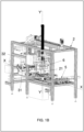
figure 1B is a second front perspective view of a machine for packaging pouch wrappings according to the present invention; -
figure 2 shows a plan view from above of the machine according to the invention; -
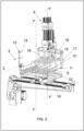
figure 3 shows a perspective view of a detail of the machine according to the invention, regarding first and second gripping means; -
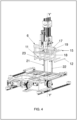
figure 4 shows a perspective view of a detail of the machine according to the invention, regarding second gripping means in a second configuration thereof; -
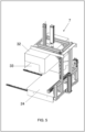
figure 5 a perspective view of a machine detail according to the invention, regarding packaging means; -
figure 6 a further perspective view of a detail of the machine according to the invention, regarding said packaging means. - An example of a machine for packaging pouch wrappings according to the invention has been identified as a whole by
reference 1 in the appended figures. - The machine in question is advantageously used in the technical area of the production and marketing of machines for packaging products, and in particular in the technical area of the packaging of pouch wrappings, such as, in particular, flexible pouches made of plastic and/or paper material or similar.
- The
machine 1 object of the present invention is advantageously applicable to a larger plant for the production of pouch wrappings, suitably placed downstream of suitable further machines (not object of the present invention and therefore not described in detail below) for making the wrapping and/or machines for making groups of pouch wrappings vertically stacked on each other. - For the purposes of this privative right, the term "pouch wrapping" is to be understood in the following as meaning a containing element, preferably flexible, made of plastic and/or paper and/or similar and/or analogous material, configured to contain at least one product inside it, in particular provided with a main body extending between a first end in which an access opening is realised for inserting the products inside it and a second end in which a closed bottom is realised, opposed to the opening. The closed bottom of each pouch wrapping is thicker than the opening.
- Furthermore, for the purposes of this privative, the term "group" of pouch wrappings is to be understood in the following as meaning a plurality of pouch wrapping vertically stacked with each other, one overlapping the other with all first ends vertically aligned with each other and all second ends vertically aligned with each other. The group of pouch wrappings therefore has a larger footprint at the second end wherein the closed ends are aligned, and a smaller footprint at the first end wherein the access apertures of the plurality of pouch wrappings comprising it are aligned.
- Furthermore, for the purposes of the present privative, the term "stack" of pouch wrappings groups is to be understood hereafter as meaning a succession of vertically stacked groups, wherein each group is rotated 180° around a vertical axis compared to the preceding group and to the following group.
- In other words, in the stack of pouch wrapping groups, the groups are stacked vertically in a staggered manner so that the openings of a first group are then covered by the closed bottoms of the next group.
- The
machine 1 for packaging pouch wrappings comprises asupport frame 2 defining aninlet section 3 for at least one group of pouch wrappings and anoutlet section 4 for packaging a plurality of pouch wrappings groups. - With particular reference to the attached figures, the
inlet section 3 and theoutlet section 4 are realised laterally compared to a longitudinal X-direction (coinciding with a movement direction X described below). Obviously, in accordance with a further, not illustrated embodiment, theinlet section 3 and theoutlet section 4 can be provided specularly compared to the highlighted one, or again theinlet section 3 can be provided on a different side compared to theoutlet section 4, without thereby departing from the purpose of protection of this privative. - In accordance with a first embodiment, the
inlet section 3 is configured to allow the entry of only one group of pouch wrappings to make a package comprising a single stack of pouch wrappings groups. - In accordance with a further embodiment, the
inlet section 3 may be configured to receive two or more groups of pouches wrappings horizontally arranged side-by-side with each other to realise a corresponding pack comprising two or more stacks of pouch wrappings groups. - The machine advantageously comprises first gripping means 5 mechanically mounted on said
support frame 2 in the proximity of saidinlet section 3 and configured and controlled to be movable at least between a loading configuration in which they receive said group of pouch wrappings, a first unloading configuration and a second unloading configuration rotated about 180° compared to said first unloading configuration. - The
machine 1 according to the invention further comprises secondgripping means 6 mechanically mounted on saidsupport frame 2 and configured and controlled to be movable between a first configuration in which they pick up said group of pouch wrappings directly from said firstgripping means 5 in said first unloading configuration with said group of pouch wrappings in a first angular position and, alternatively, in said second unloading configuration with said group of pouch wrappings in a second angular position, and a second configuration in which they release said group of pouch wrappings to form a stack of pouch wrappings groups. - Suitably, the stack of pouch wrappings groups is made with groups vertically stacked with each other in the first angular position and in the second angular position alternately. Advantageously, the packaging means 7 are mechanically mounted on said
support frame 2 and configured to receive said stack of pouch wrappings groups and wrap said stack with at least one layer of flexible material and thus realize said package. - Advantageously, said first
gripping means 5 are configured to rotate about a first substantially vertical rotation axis Y, wherein said first unloading configuration is rotated about 90° clockwise compared to said loading configuration and said second unloading configuration is rotated about 90° counter clockwise compared to said loading configuration. - Advantageously, said second
gripping means 6 are configured at least to rotate about a second rotation axis Y' substantially vertical and parallel to said first rotation axis Y of said firstgripping means 5, wherein in a first angular position they are turned towards said firstgripping means 5 to pick up said group of pouch wrappings and in a second angular position they are turned towards said packaging means 7. - Advantageously, said second
gripping means 6 in said second configuration are intersected with said firstgripping means 5 in said first unloading configuration or in said second unloading configuration to pick up said pouch wrappings group. Advantageously, said first gripping means comprise afirst loading base 9 configured to support said pouch wrappings groups and comprising a first series ofelongated elements 10 parallel to each other and spaced apart. - Advantageously, said second
gripping means 6 comprise asecond loading base 11 configured to support said pouch wrappings group and comprising a second series ofelongated elements 12 parallel to each other and spaced apart and configured to be interposed between said first series ofelongated elements 10 with said secondgripping means 6 in said first configuration. - Advantageously, said first
gripping means 5 comprise anupper jaw 13 movable between an open configuration, wherein it is moved away from saidfirst loading base 9 to allow said pouch wrappings group to rest on saidfirst loading base 9, and a closed configuration wherein it is placed substantially counter faced to saidfirst loading base 9 to block said pouch wrappings group. - Preferably, the
upper jaw 13 of the firstgripping means 5 is rotatably mounted at an end of saidfirst loading base 9 and is rotatably movable around a rotation axis Z orthogonal compared to said first rotation axis Y and preferably is substantially horizontal. In this way, theupper jaw 13 is rotatable around the horizontal rotation axis X between the open configuration and the closed configuration. - Suitably, the first
gripping means 5 block the pouch wrappings group on thefirst loading base 9 by movement of the firstupper jaw 13 from the open configuration to the closed configuration, such that the pouch wrappings group remains stable during movement of the firstgripping means 5 from the loading configuration to the first unloading configuration or to the second unloading configuration. - Furthermore, the first
upper jaw 13 of the firstgripping means 5 is configured to be moved from the closed configuration to the open configuration when the firstgripping means 5 themselves reach the first unloading configuration or the second unloading configuration. In this way, the firstgripping means 5 allow the secondgripping means 6 to pick up the pouch wrappings group. - Advantageously, said
upper jaw 13 of said firstgripping means 5 comprises a third series ofelongated elements 14 which are parallel to each other and spaced apart and arranged vertically offset from corresponding first series ofelongated elements 10, thereby defining spaces between them to allow the insertion of said second series ofelongated elements 12 with said secondgripping means 6 in said first configuration. - Preferably, the second
gripping means 6 comprise a secondupper jaw 15 movable between an open configuration, wherein it is moved away from saidsecond loading base 11 to allow the pick-up of said set of pouch wrappings from said firstgripping means 5, and a closed configuration wherein it is placed substantially counter faced to saidsecond loading base 11 to block said set of pouch wrappings, in particular to hold them against saidsecond loading base 11. - Advantageously, the second
gripping means 6 are movable along a movement direction X, substantially orthogonal compared to the second rotation axis Y'. - Advantageously, the first series of
elongated elements 10 of thefirst loading base 9 of the firstgripping means 5 and preferably the second series ofelongated elements 12 of thesecond loading base 11 are movable parallel to the movement direction X, i.e. they are movable substantially horizontally. - Appropriately, the second
gripping means 6 are moved along the movement direction X towards the first gripping means to intersect the second series ofelongated elements 12 of thesecond loading base 11 with the first series ofelongated elements 10 of thefirst loading base 9. Advantageously, the second series ofelongated elements 12, as intersected with the first series ofelongated elements 10, is placed at an equal and preferably lower height than the height at which the first series ofelongated elements 10 is arranged. Advantageously, with the secondgripping means 6 intersected with the firstgripping means 5, the firstupper jaw 13 is placed in its open configuration to allow the secondgripping means 6 to pick up the pouch wrapping. - For this purpose, the second
gripping means 6, with the second series ofelongated elements 12 placed below the first series ofelongated elements 10 and thus below the pouch wrappings group resting on thefirst loading base 9, are moved vertically along the second rotation axis Y', so that the second series ofelongated elements 12 passes between the first series ofelongated elements 10, thereby picking up the pouch wrappings group. It is clear that the secondgripping means 6 pick up the pouch wrappings group in the same angular position in which they are presented by the firstgripping means 5, i.e. in particular with the closed bottoms arranged either on one side or on the other side of thesecond loading base 11. - Advantageously, the movement of the second
gripping means 6 is numerically controlled by an electronic control unit and is commanded to intersect with the firstgripping means 5 for a linear distance equal to or greater than the width of the pouch wrapping. Suitably, in the case where a package is to be made with more than one stack of pouch wrappings, the electronic control unit controls the movement of the secondgripping means 6 along the movement direction X for a linear distance equal to a multiple of the width of the pouch wrappings. For example, if a pack is to be made with two groups stacks, then the secondgripping means 6 will move at the intersection of the firstgripping means 5 by a distance equal to or greater than two times the width of the gripping means. Appropriately, following the pick-up of the pouch wrappings group, the secondgripping means 6 is moved from its open configuration to the second closed configuration. Advantageously, the first series ofelongated elements 10 of thefirst loading base 9 are movable towards or away from each other to define afirst loading base 9 of different width. - Similarly, advantageously, the second series of
elongated elements 12 of thesecond loading base 11 are movable towards or away from each other to define asecond loading base 11 of different amplitude. - In a preferred embodiment, the first
gripping means 5 comprise asupport ferrule 16 on which theelongated elements 10 of thefirst loading base 9 are mounted. - The
support ferrule 16 is interchangeable by an operator with aferrule 16 havingelongated elements 10 at different relative spacing. - Advantageously, the second
gripping means 6 comprise a support crossbar17 extending transversely compared to the second rotation axis Y' and compared to the movement direction X and preferably substantially horizontally, on which theelongated elements 12 are fixed. In particular, theelongated elements 12 of thesecond loading base 11 are fixed to the support crossbarl7 by means of corresponding fixingpillars 18 extending parallel to the second rotation axis Y'. - In fact, in accordance with the preferred embodiment illustrated in the attached figures, the support crossbar 17 (preferably fixed) is arranged at a higher height than the
second loading base 11 defined by the second series ofelongated elements 12. Therefore, the fixingpillars 18 are arranged as a mechanical connection between thesupport crossbar 17 and theelongated elements 12 thereof. - Suitably, the
support crossbar 17 is provided with mechanical coupling means, comprising in particular a plurality ofholes 19 arranged along its prevailing extension and configured to be occupied by corresponding mechanical coupling counter-means of the fixingpillars 18. - In this way, the operator is able to vary the relative distance between the second series of
elongated elements 12 of thesecond loading base 11 on the basis of necessity, i.e. on the basis of, for example, a different size of the pouch wrapping. - Advantageously, the
machine 1 comprises a stackingzone 8 configured to receive said stack of pouch wrappings groups is configured to be moved parallel to a substantially horizontal movement direction X to transport said stack towards said packaging means 7. - Advantageously, the stacking
zone 8 of themachine 1 advantageously comprises aplatform 20 configured to support the pouch wrappings group stacked with each other, arranged by the secondgripping means 6. - Advantageously, in accordance with a first embodiment, the
platform 20 of the stackingzone 8 may support a single stack of pouch wrappings group. Advantageously, in accordance with a further embodiment of the present invention, theplatform 20 of the stackingzone 8 may be configured and/or dimensioned to support two or more stacks of pouch wrappings groups. - For the purpose of enabling the unloading of the pouch wrappings groups, the stacking
zone 8 advantageously comprises stop means 21, extending substantially vertically and configured to act as a stop and/or end-stack for the pouch wrappings group arranged by the secondgripping means 6. - More in detail, the second gripping means are configured to be moved along the direction X until reaching the second series of
elongated elements 12 the stackingzone 8, at a higher height than the stop means 21, as long as the group of pouch casings exceeds, along the movement direction X, the stop barrier means 21. - Advantageously, said second
gripping means 6 are movable, preferably vertically, at least along said second rotation axis Y' to release said pouch wrappings group above at least one further pouch wrappings group. - Suitably, in other words, with the second series of
elongated elements 12 beyond the stop means 21, the secondgripping means 6 are moved vertically along said second rotation axis Y' until the pouch wrappings group supported by thesecond loading base 11 reaches theplatform 20 or reaches another pouch wrappings group(arranged in another angular position, i.e. with the bottom arranged on the other side). - Upon reaching such a position, the second
gripping means 6 are moved in the open configuration and thus along the movement direction X. During such movement along the movement direction X, the pouch wrappings group encounters the stop means 21 which block their movement, holding them in their position on theplatform 20, thus creating a stack of pouch wrappings groups staggered between them, i.e. alternately provided with a different angular position. In other words, the stack of pouch wrappings group is advantageously formed against the stop means 21 and the assemblies are arranged such that the bottom of one assembly is overlaid by the openings of a subsequent assembly and vice versa. - Advantageously, the stop means 21 comprise at least one
pillar 22 and preferably twopillars 22 parallel to each other and configured to be interposed to the second series ofelongated elements 12 of thesecond loading base 11 of the secondgripping means 6. Advantageously, the at least onepillar 22 of the stop means 21 comprises, at an upper free end thereof, awheel 23 configured to assist the descent of the pouch wrappings group with the second gripping means and, preferably, to assist the handling of the flexible material layer of the packaging means 7, as described in more detail below. Advantageously, the stop means 21 are movable parallel to the movement direction X to push the stack of pouch wrappings group towards the packaging means 7. - The packaging means 7 comprise at least one
support base 24 configured to support the stack of pouch wrappings group pushed by the stop means 21 from the stackingzone 8. Suitably, a tract of aflexible material layer 25 is interposed between the stop means 21 and thesupport base 24 of the packaging means, which extends substantially vertically. More in detail, the layer offlexible material 25 is maintained in said vertical position by suitable tensioning means 26 comprising at least one reel and preferably tworeels 27 of flexible material. - In accordance with the embodiment illustrated in the annexed figures, the tensioning means 26 comprise two
reels 27 of flexible material web, preferably rotatably constrained to thesupport frame 2, around corresponding preferably horizontal and parallel axes of rotation, at one end thereof, located in proximity to thesupport base 24. - Each
reel 27 is unrolled in the opposite direction to the other and the free edges of each strip of flexible material are mechanically constrained to each other at the section of flexible material interposed between the stop means 21 and the packaging means 7. - Operationally, the stack of pouch wrappings group pushed by the stop means 21 intercepts the vertical tract of
flexible material 25, which wraps itself around the same stack, partially wrapping it until the stack reaches thesupport base 24 of the packaging means 7. - More in detail, the
tract 25 of flexible material wraps around a front part of the stack and defines two substantially horizontal or inclined tracts, with the stack placed above thesupport base 24. - For this purpose, the
reels 27 of flexible material are unrolled to allow proper wrapping of the stack and preferably are actively unroll by at least oneelectric motor 28 connected to at least onereel 27. Active unrolling of thereels 27 obviates the risk that the pulling performed by the pushing of the stop means 21 and the tapping of the stack will tear and/or damage the flexible material. - Preferably, the
flexible material 25 is a plastic material, e.g. transparent, such as a polyethylene or similar. - Suitably, the packaging means 7 comprise a sealing and cutting
device 29 interposed between the stop means 21 and thetract 25 of flexible material, preferably comprising at least one sealing bar, which extends horizontally transversely compared to the movement direction X and is movable between a raised position in which it allows the passage of the 21 pushing the stack of pouch wrappings groups and a lowered position in which it intercepts the substantially horizontal or inclined layers of flexible material and thermally joins and seals them together, thereby creating a horizontal sealing line. - Suitably, the sealing and cutting
device 29 further comprises at least one cutting bar, arranged parallel to the sealing bar. - Preferably, the sealing and cutting
device 29 comprises two sealing bars. Preferably, the cutting bar of the sealing and cuttingdevice 29 is interposed between the two sealing bars, such that with the sealing and cuttingdevice 29 intercepting substantially horizontal or inclined sections of the flexible material seals along the two sealing lines made by the two sealing bars and cuts along a cutting line interposed between the two sealing lines. In this way, the sealing and cuttingdevice 29 allows the plastic material to be closed around the stack of pouch wrappings groups and simultaneously joins together the free edges of the plastic material strips unroll from the two reels to define again avertical tract 25 of flexible material intended to be intercepted again by a subsequent stack of pouch wrappings groups. - Suitably, the packaging means 7 comprise a heating means 30 provided at the
support base 24 and configured to heat the flexible plastic material wrapping the stack of pouch wrappings group. - Preferably, the plastic material is a shrinkable material, i.e. configured to decrease its extension when exposed to a heat source. Thus, the heating means 30 are configured to shrink the plastic material wrapping the stack and thus make a compact and easy to handle and transport package.
- Preferably, the heating means 30 comprise a device for delivering a flow of hot air, in particular comprising at least one
duct 31 and preferably twoducts 31 arranged on the sides of thesupport base 24, in particular symmetrically compared to the movement direction X. Theducts 31 terminate with exhaust ports facing a volume defined above thesupport base 24 intended to be occupied by the stack wrapped by the flexible material. Advantageously, the discharge outlets of theducts 31 of the heating means 30 are configured to emit said flow of hot air over the side edges of the shrinkable plastic material in order to make them retract and thus wrap the stack of pouch wrappings groups. - Advantageously, the packaging means 7 comprise at least one covering
body 32 movable between a position distal to thesupport base 24, to allow the arrival of the stack wrapped by the plastic material, and a position proximal to the support base in which it covers superiorly (and preferably at least partially also laterally) the volume defined superiorly to thesupport base 24 and thus the stack of pouch wrappings groups. The coveringbody 32 is provided withside openings 33 configured to be aligned with theduct discharge outlets 31 when in the position proximal to thesupport base 24 to allow the flow of hot air to enter it. - The covering
body 32 is configured to retain within it the hot air and thus the heat generated by the heating means 30. - Advantageously, the
machine 1 according to the invention comprises at least one electronic control unit (not illustrated in the appended figures), at which it is configured and/or programmed to control the movement of appropriate handling means mechanically mounted on the support frame. - More in detail, the movement means are configured to move each moving part of the
machine 1, for example the movement of the first and secondgripping means device 29 etc. - Advantageously, the
machine 1 comprises at least one user interface device, for example a screen and at least one numeric keypad and/or a touch screen, for setting initial working parameters, such as for example the size of the pouch wrappings, the number of group stacks desired in the final package, etc. - Advantageously, the movement of the moving parts of
machine 1 is carried out in feedback and/or numerical control on the basis of appropriate command signals sent by the electronic control unit. - From what has been said, it is clear that the pouch wrappings machine, according to the invention, is particularly advantageous in that:
- allows to satisfy, at least in part, the aforementioned requirements and to overcome the drawbacks of the aforementioned known art;
- it is more easily feasible than the known art;
- it is more economical than the known art;
- it is economically advantageous and at the same time technically completely reliable;
- it is alternative and/or improved compared to conventional solutions;
- has an alternative and/or improved configuration, both in terms of construction and function, compared to traditional solutions.
- The present invention has been illustrated and described in a preferred embodiment, but it is understood that executive variations may be made to it in practice, without, however, going beyond the scope of protection of the present patent for industrial invention.
Claims (15)
- Machine for packaging pouch wrapping, comprising:- a support frame (2) defining an inlet section (3) for at least one pouch wrapping group and an outlet section (4) for a package of a plurality of pouch wrapping groups;- first gripping means (5) mechanically mounted on said support frame (2) in proximity of said inlet section (3) and configured and controlled to be movable at least between a loading configuration in which they receive said pouch wrapping group , a first unloading configuration and a second unloading configuration rotated about 180° compared to said first unloading configuration;- packaging means (7) mechanically mounted on said support frame (2) and configured to receive said stack of pouch wrapping group and wrap said stack with at least one layer of flexible material and thus make said package;- second gripping means (6) mechanically mounted on said support frame (2); said machine being characterised in that said second gripping means (6) are configured and controlled to be movable between a first configuration in which they pick up said pouch wrapping group directly from said first gripping means (5) in said first unloading configuration with said pouch wrapping group in a first angular position, and alternatively, in said second unloading configuration with said pouch wrapping group in a second angular position, and a second configuration in which they release said pouch wrapping group to form a stack of pouch wrapping group;said stack of pouch wrapping group being made with pouch wrapping groups stacked vertically together in the first angular position and in the second angular position in an alternating manner.
- Machine for packaging pouch wrapping according to claim 1, characterised in that said first gripping means (5) are configured to rotate about a first rotation axis (Y) substantially vertical, wherein said first unloading configuration is rotated about 90° clockwise compared to said loading configuration and said second unloading configuration is rotated about 90° counter-clockwise compared to said loading configuration.
- Machine for packaging pouch wrapping according to claim 2, characterised in that said second gripping means (6) are configured at least to rotate about a second rotation axis (Y') substantially vertical and parallel to said first rotation axis (Y) of said first gripping means (5), wherein in a first angular position they are turned towards said first gripping means (5) to pick up said pouch wrapping group and in a second angular position they are turned towards said packaging means (7).
- Machine for packaging pouch wrapping according to one or more of the preceding claims, characterized in that said second gripping means (6) in said second configuration are intersected with said first gripping means (5) in said first unloading configuration or in said second unloading configuration to pick up said pouch wrapping group.
- Machine for packaging pouch wrapping according to claim 4, characterised in that said first gripping means comprise a first loading base (9) configured to support said pouch wrapping group and comprising a first series of elongated elements (10) parallel to each other and spaced apart.
- Machine for packaging pouch wrapping according to claim 5, characterised in that said second gripping means comprise a second loading base (11) configured to support said pouch wrapping group and comprising a second series of elongated elements (12) parallel to each other and spaced apart and configured to be interposed between said first series of elongated elements (10) with said second gripping means (6) in said first configuration.
- Machine for packaging pouch wrapping according to claim 5 or 6, characterised in that said first gripping means comprise an upper jaw (13) movable between an open configuration, wherein it is displaced from said first loading base (9) to allow support of said pouch wrapping group on said first loading base (9), and a closed configuration wherein it is placed substantially counterfeited to said first loading base (9) to block said pouch wrapping group.
- Machine for packaging pouch wrapping according to claim 7, characterised in that said upper jaw (13) of said first gripping means (5) comprises a third series of elongated elements (14) parallel to each other and spaced apart and arranged vertically counterfeited to corresponding first series of elongated elements (10), thus defining spaces between them to allow the insertion of said second series of elongated elements (12) with said second gripping means (6) in said first configuration.
- Machine for packaging pouch wrapping according to one or more of the preceding claims, characterised in that said second gripping means (6) are movable at least along said second rotation axis (Y') to release said pouch wrapping group above at least one further pouch wrapping group.
- Machine for packaging pouch wrappers according to one or more of the preceding claims, characterised in that it comprises a stacking zone (8) configured to receive said stack of pouch wrapping group and configured to be moved parallel to a substantially horizontal movement direction (X) for conveying said stack towards said packaging means (7).
- Machine for packaging pouch wrapping according to one or more of the preceding claims, characterised in that said first gripping means (5) lock said pouch wrapping group on said first loading base (9) by movement of said first jaw (13) from the open configuration to the closed configuration, such that said pouch wrapping group remains stable during movement of said first gripping means (5) from the loading configuration to the first unloading configuration or to the second unloading configuration.
- Machine for packaging pouch wrapping according to one or more of the preceding claims, characterised in that said first jaw (13) of said first gripping means (5) is configured to be moved from the closed configuration to the open configuration when said first gripping means (5) reach the first unloading configuration or the second unloading configuration.
- Machine for packaging pouch wrapping according to one or more of the preceding claims, characterised in that said second gripping means (6) comprise a second upper jaw (15) movable between an open configuration, wherein it is displaced from said second loading base (11) to allow picking up of said pouch wrapping group from said first gripping means (5), and a closed configuration wherein it is placed substantially counterfeited to said second loading base (11) to block said pouch wrapping group.
- Machine for packaging pouch wrapping according to one or more of the preceding claims, characterised in that the movement of the second gripping means (6) is numerically controlled by an electronic control unit and is controlled to intersect with the first gripping means (5) for a linear distance equal to or greater than the width of the pouch wrapping.
- Machine for packaging pouch wrapping according to one or more of the preceding claims, characterised in that the first series of elongated elements (10) of the first loading base (9) are movable towards or away from each other to define a first loading base (9) of different widths.
Applications Claiming Priority (1)
| Application Number | Priority Date | Filing Date | Title |
|---|---|---|---|
| IT102021000032072A IT202100032072A1 (en) | 2021-12-21 | 2021-12-21 | MACHINE FOR PACKAGING BAGS |
Publications (3)
| Publication Number | Publication Date |
|---|---|
| EP4201822A1 true EP4201822A1 (en) | 2023-06-28 |
| EP4201822C0 EP4201822C0 (en) | 2024-09-18 |
| EP4201822B1 EP4201822B1 (en) | 2024-09-18 |
Family
ID=80625185
Family Applications (1)
| Application Number | Title | Priority Date | Filing Date |
|---|---|---|---|
| EP22214752.2A Active EP4201822B1 (en) | 2021-12-21 | 2022-12-19 | Machine for packaging groups of pouch wrappings |
Country Status (2)
| Country | Link |
|---|---|
| EP (1) | EP4201822B1 (en) |
| IT (1) | IT202100032072A1 (en) |
Citations (5)
| Publication number | Priority date | Publication date | Assignee | Title |
|---|---|---|---|---|
| EP0146643A1 (en) * | 1983-12-06 | 1985-07-03 | Icoma Packtechnik GmbH | Pallet loader |
| EP1657191A1 (en) * | 2004-11-12 | 2006-05-17 | Bema s.r.l. | A process and plant for palletizing deformable and unstable containers |
| US20100146907A1 (en) | 2008-11-21 | 2010-06-17 | Dematic Corp. | Stacking apparatus and method of multi-layer stacking of objects on a support |
| US8997438B1 (en) | 2012-09-18 | 2015-04-07 | David M. Fallas | Case packing system having robotic pick and place mechanism and dual dump bins |
| US20200361650A1 (en) * | 2017-08-16 | 2020-11-19 | Ishida Co., Ltd. | Box packing apparatus |
-
2021
- 2021-12-21 IT IT102021000032072A patent/IT202100032072A1/en unknown
-
2022
- 2022-12-19 EP EP22214752.2A patent/EP4201822B1/en active Active
Patent Citations (5)
| Publication number | Priority date | Publication date | Assignee | Title |
|---|---|---|---|---|
| EP0146643A1 (en) * | 1983-12-06 | 1985-07-03 | Icoma Packtechnik GmbH | Pallet loader |
| EP1657191A1 (en) * | 2004-11-12 | 2006-05-17 | Bema s.r.l. | A process and plant for palletizing deformable and unstable containers |
| US20100146907A1 (en) | 2008-11-21 | 2010-06-17 | Dematic Corp. | Stacking apparatus and method of multi-layer stacking of objects on a support |
| US8997438B1 (en) | 2012-09-18 | 2015-04-07 | David M. Fallas | Case packing system having robotic pick and place mechanism and dual dump bins |
| US20200361650A1 (en) * | 2017-08-16 | 2020-11-19 | Ishida Co., Ltd. | Box packing apparatus |
Also Published As
| Publication number | Publication date |
|---|---|
| IT202100032072A1 (en) | 2023-06-21 |
| EP4201822C0 (en) | 2024-09-18 |
| EP4201822B1 (en) | 2024-09-18 |
Similar Documents
| Publication | Publication Date | Title |
|---|---|---|
| EP1988020B1 (en) | Equipment and process for continuously making stack packages of tiles or the like | |
| CN102358445B (en) | The equipment of wrap film and method around stack of articles | |
| ES2304648T3 (en) | MACHINE TO PACK IN SEMIAUTOMATIC BOXES. | |
| JP2019520238A (en) | Corrugated blank folding station and machine for packing articles in corrugated boxes obtained from corrugated blanks | |
| JPS5952092B2 (en) | Device for forming pallet-free stacks of single cargo, especially bags, surrounded by sheets | |
| EP0860356B1 (en) | Apparatus for placing groups of products on pallets | |
| JPH0343323A (en) | Manufacturing factory of large unit of cleansing tissue | |
| EP4201822B1 (en) | Machine for packaging groups of pouch wrappings | |
| JP7492579B2 (en) | Packaging machine for producing filter bags containing infusion products | |
| US6935091B2 (en) | Method and apparatus for wrapping articles with a packaging sheet | |
| CN101181938B (en) | Sheet material supplying apparatus and sheet packing machine employing the same | |
| CN120897875A (en) | Machines and methods for forming layers of a product | |
| EP1775233B1 (en) | Outer package for packaged groups of rolls of products. | |
| US20250074639A1 (en) | An apparatus for packaging articles | |
| JP2004155428A (en) | Boxing equipment | |
| KR100485788B1 (en) | Machine for packaging four-sides of hexahedral goods | |
| EP2392513B1 (en) | Equipment, method and station for lateral wrapping of products by means of plastic film | |
| WO2014078828A1 (en) | Method and system for conveying rolled absorbent products | |
| EP1254839B1 (en) | Method and apparatus for wrapping articles with a packaging sheet | |
| EP0532785B1 (en) | Film-wrapping and boxing machine particularly for spools of thread and the like | |
| JP7614645B2 (en) | Position shift prevention device and packaging machine | |
| CN112839872A (en) | Apparatus and method for gathering and unloading items | |
| ITMI950774A1 (en) | DEVICE FOR FOLDING THE FOLDING FLAPS OF A PACKAGE AND TO TRANSPORT THE SAME | |
| EP4671141A2 (en) | PACKING MACHINE FOR PACKING POUCH SUBSTRATES | |
| GB2573779A (en) | Multi-pack and method of making a multi-pack |
Legal Events
| Date | Code | Title | Description |
|---|---|---|---|
| PUAI | Public reference made under article 153(3) epc to a published international application that has entered the european phase |
Free format text: ORIGINAL CODE: 0009012 |
|
| STAA | Information on the status of an ep patent application or granted ep patent |
Free format text: STATUS: THE APPLICATION HAS BEEN PUBLISHED |
|
| AK | Designated contracting states |
Kind code of ref document: A1 Designated state(s): AL AT BE BG CH CY CZ DE DK EE ES FI FR GB GR HR HU IE IS IT LI LT LU LV MC ME MK MT NL NO PL PT RO RS SE SI SK SM TR |
|
| STAA | Information on the status of an ep patent application or granted ep patent |
Free format text: STATUS: REQUEST FOR EXAMINATION WAS MADE |
|
| 17P | Request for examination filed |
Effective date: 20231115 |
|
| RBV | Designated contracting states (corrected) |
Designated state(s): AL AT BE BG CH CY CZ DE DK EE ES FI FR GB GR HR HU IE IS IT LI LT LU LV MC ME MK MT NL NO PL PT RO RS SE SI SK SM TR |
|
| GRAP | Despatch of communication of intention to grant a patent |
Free format text: ORIGINAL CODE: EPIDOSNIGR1 |
|
| STAA | Information on the status of an ep patent application or granted ep patent |
Free format text: STATUS: GRANT OF PATENT IS INTENDED |
|
| RIC1 | Information provided on ipc code assigned before grant |
Ipc: B65B 35/50 20060101ALI20240404BHEP Ipc: B65B 5/06 20060101ALI20240404BHEP Ipc: B65B 35/52 20060101ALI20240404BHEP Ipc: B65B 35/56 20060101ALI20240404BHEP Ipc: B65B 35/36 20060101ALI20240404BHEP Ipc: B65B 35/16 20060101ALI20240404BHEP Ipc: B65B 11/00 20060101AFI20240404BHEP |
|
| INTG | Intention to grant announced |
Effective date: 20240418 |
|
| GRAS | Grant fee paid |
Free format text: ORIGINAL CODE: EPIDOSNIGR3 |
|
| GRAA | (expected) grant |
Free format text: ORIGINAL CODE: 0009210 |
|
| STAA | Information on the status of an ep patent application or granted ep patent |
Free format text: STATUS: THE PATENT HAS BEEN GRANTED |
|
| AK | Designated contracting states |
Kind code of ref document: B1 Designated state(s): AL AT BE BG CH CY CZ DE DK EE ES FI FR GB GR HR HU IE IS IT LI LT LU LV MC ME MK MT NL NO PL PT RO RS SE SI SK SM TR |
|
| REG | Reference to a national code |
Ref country code: GB Ref legal event code: FG4D |
|
| REG | Reference to a national code |
Ref country code: CH Ref legal event code: EP |
|
| REG | Reference to a national code |
Ref country code: IE Ref legal event code: FG4D |
|
| REG | Reference to a national code |
Ref country code: DE Ref legal event code: R096 Ref document number: 602022006215 Country of ref document: DE |
|
| U01 | Request for unitary effect filed |
Effective date: 20241015 |
|
| U07 | Unitary effect registered |
Designated state(s): AT BE BG DE DK EE FI FR IT LT LU LV MT NL PT RO SE SI Effective date: 20241031 |
|
| PG25 | Lapsed in a contracting state [announced via postgrant information from national office to epo] |
Ref country code: NO Free format text: LAPSE BECAUSE OF FAILURE TO SUBMIT A TRANSLATION OF THE DESCRIPTION OR TO PAY THE FEE WITHIN THE PRESCRIBED TIME-LIMIT Effective date: 20241218 |
|
| PG25 | Lapsed in a contracting state [announced via postgrant information from national office to epo] |
Ref country code: GR Free format text: LAPSE BECAUSE OF FAILURE TO SUBMIT A TRANSLATION OF THE DESCRIPTION OR TO PAY THE FEE WITHIN THE PRESCRIBED TIME-LIMIT Effective date: 20241219 |
|
| PG25 | Lapsed in a contracting state [announced via postgrant information from national office to epo] |
Ref country code: HR Free format text: LAPSE BECAUSE OF FAILURE TO SUBMIT A TRANSLATION OF THE DESCRIPTION OR TO PAY THE FEE WITHIN THE PRESCRIBED TIME-LIMIT Effective date: 20240918 |
|
| PG25 | Lapsed in a contracting state [announced via postgrant information from national office to epo] |
Ref country code: RS Free format text: LAPSE BECAUSE OF FAILURE TO SUBMIT A TRANSLATION OF THE DESCRIPTION OR TO PAY THE FEE WITHIN THE PRESCRIBED TIME-LIMIT Effective date: 20241218 |
|
| PG25 | Lapsed in a contracting state [announced via postgrant information from national office to epo] |
Ref country code: RS Free format text: LAPSE BECAUSE OF FAILURE TO SUBMIT A TRANSLATION OF THE DESCRIPTION OR TO PAY THE FEE WITHIN THE PRESCRIBED TIME-LIMIT Effective date: 20241218 Ref country code: NO Free format text: LAPSE BECAUSE OF FAILURE TO SUBMIT A TRANSLATION OF THE DESCRIPTION OR TO PAY THE FEE WITHIN THE PRESCRIBED TIME-LIMIT Effective date: 20241218 Ref country code: HR Free format text: LAPSE BECAUSE OF FAILURE TO SUBMIT A TRANSLATION OF THE DESCRIPTION OR TO PAY THE FEE WITHIN THE PRESCRIBED TIME-LIMIT Effective date: 20240918 Ref country code: GR Free format text: LAPSE BECAUSE OF FAILURE TO SUBMIT A TRANSLATION OF THE DESCRIPTION OR TO PAY THE FEE WITHIN THE PRESCRIBED TIME-LIMIT Effective date: 20241219 |
|
| U21 | Renewal fee for the european patent with unitary effect paid with additional fee |
Year of fee payment: 3 Effective date: 20250228 |
|
| PG25 | Lapsed in a contracting state [announced via postgrant information from national office to epo] |
Ref country code: IS Free format text: LAPSE BECAUSE OF FAILURE TO SUBMIT A TRANSLATION OF THE DESCRIPTION OR TO PAY THE FEE WITHIN THE PRESCRIBED TIME-LIMIT Effective date: 20250118 |
|
| PG25 | Lapsed in a contracting state [announced via postgrant information from national office to epo] |
Ref country code: SM Free format text: LAPSE BECAUSE OF FAILURE TO SUBMIT A TRANSLATION OF THE DESCRIPTION OR TO PAY THE FEE WITHIN THE PRESCRIBED TIME-LIMIT Effective date: 20240918 |
|
| PG25 | Lapsed in a contracting state [announced via postgrant information from national office to epo] |
Ref country code: ES Free format text: LAPSE BECAUSE OF FAILURE TO SUBMIT A TRANSLATION OF THE DESCRIPTION OR TO PAY THE FEE WITHIN THE PRESCRIBED TIME-LIMIT Effective date: 20240918 |
|
| PG25 | Lapsed in a contracting state [announced via postgrant information from national office to epo] |
Ref country code: CZ Free format text: LAPSE BECAUSE OF FAILURE TO SUBMIT A TRANSLATION OF THE DESCRIPTION OR TO PAY THE FEE WITHIN THE PRESCRIBED TIME-LIMIT Effective date: 20240918 Ref country code: PL Free format text: LAPSE BECAUSE OF FAILURE TO SUBMIT A TRANSLATION OF THE DESCRIPTION OR TO PAY THE FEE WITHIN THE PRESCRIBED TIME-LIMIT Effective date: 20240918 |
|
| PG25 | Lapsed in a contracting state [announced via postgrant information from national office to epo] |
Ref country code: SK Free format text: LAPSE BECAUSE OF FAILURE TO SUBMIT A TRANSLATION OF THE DESCRIPTION OR TO PAY THE FEE WITHIN THE PRESCRIBED TIME-LIMIT Effective date: 20240918 |
|
| PG25 | Lapsed in a contracting state [announced via postgrant information from national office to epo] |
Ref country code: MC Free format text: LAPSE BECAUSE OF FAILURE TO SUBMIT A TRANSLATION OF THE DESCRIPTION OR TO PAY THE FEE WITHIN THE PRESCRIBED TIME-LIMIT Effective date: 20240918 |
|
| PLBE | No opposition filed within time limit |
Free format text: ORIGINAL CODE: 0009261 |
|
| STAA | Information on the status of an ep patent application or granted ep patent |
Free format text: STATUS: NO OPPOSITION FILED WITHIN TIME LIMIT |
|
| 26N | No opposition filed |
Effective date: 20250619 |
|
| PG25 | Lapsed in a contracting state [announced via postgrant information from national office to epo] |
Ref country code: IE Free format text: LAPSE BECAUSE OF NON-PAYMENT OF DUE FEES Effective date: 20241219 |
|
| U21 | Renewal fee for the european patent with unitary effect paid with additional fee |
Year of fee payment: 4 Effective date: 20260126 |
|
| PG25 | Lapsed in a contracting state [announced via postgrant information from national office to epo] |
Ref country code: CY Free format text: LAPSE BECAUSE OF FAILURE TO SUBMIT A TRANSLATION OF THE DESCRIPTION OR TO PAY THE FEE WITHIN THE PRESCRIBED TIME-LIMIT Effective date: 20240918 |
|
| PG25 | Lapsed in a contracting state [announced via postgrant information from national office to epo] |
Ref country code: TR Free format text: LAPSE BECAUSE OF FAILURE TO SUBMIT A TRANSLATION OF THE DESCRIPTION OR TO PAY THE FEE WITHIN THE PRESCRIBED TIME-LIMIT Effective date: 20240918 |
|
| PG25 | Lapsed in a contracting state [announced via postgrant information from national office to epo] |
Ref country code: HU Free format text: LAPSE BECAUSE OF FAILURE TO SUBMIT A TRANSLATION OF THE DESCRIPTION OR TO PAY THE FEE WITHIN THE PRESCRIBED TIME-LIMIT; INVALID AB INITIO Effective date: 20221219 |
|
| PG25 | Lapsed in a contracting state [announced via postgrant information from national office to epo] |
Ref country code: ME Free format text: LAPSE BECAUSE OF FAILURE TO SUBMIT A TRANSLATION OF THE DESCRIPTION OR TO PAY THE FEE WITHIN THE PRESCRIBED TIME-LIMIT Effective date: 20240925 |
|
| REG | Reference to a national code |
Ref country code: CH Ref legal event code: H13 Free format text: ST27 STATUS EVENT CODE: U-0-0-H10-H13 (AS PROVIDED BY THE NATIONAL OFFICE) Effective date: 20260723 |