EP4201805A1 - Marine vessel and control method for marine vessel propulsion control system - Google Patents
Marine vessel and control method for marine vessel propulsion control system Download PDFInfo
- Publication number
- EP4201805A1 EP4201805A1 EP22210821.9A EP22210821A EP4201805A1 EP 4201805 A1 EP4201805 A1 EP 4201805A1 EP 22210821 A EP22210821 A EP 22210821A EP 4201805 A1 EP4201805 A1 EP 4201805A1
- Authority
- EP
- European Patent Office
- Prior art keywords
- marine vessel
- control
- operation piece
- lateral direction
- propulsion devices
- Prior art date
- Legal status (The legal status is an assumption and is not a legal conclusion. Google has not performed a legal analysis and makes no representation as to the accuracy of the status listed.)
- Granted
Links
Images






Classifications
-
- B—PERFORMING OPERATIONS; TRANSPORTING
- B63—SHIPS OR OTHER WATERBORNE VESSELS; RELATED EQUIPMENT
- B63H—MARINE PROPULSION OR STEERING
- B63H25/00—Steering; Slowing-down otherwise than by use of propulsive elements; Dynamic anchoring, i.e. positioning vessels by means of main or auxiliary propulsive elements
- B63H25/42—Steering or dynamic anchoring by propulsive elements; Steering or dynamic anchoring by propellers used therefor only; Steering or dynamic anchoring by rudders carrying propellers
-
- B—PERFORMING OPERATIONS; TRANSPORTING
- B63—SHIPS OR OTHER WATERBORNE VESSELS; RELATED EQUIPMENT
- B63H—MARINE PROPULSION OR STEERING
- B63H25/00—Steering; Slowing-down otherwise than by use of propulsive elements; Dynamic anchoring, i.e. positioning vessels by means of main or auxiliary propulsive elements
- B63H25/02—Initiating means for steering, for slowing down, otherwise than by use of propulsive elements, or for dynamic anchoring
- B63H25/04—Initiating means for steering, for slowing down, otherwise than by use of propulsive elements, or for dynamic anchoring automatic, e.g. reacting to compass
-
- B—PERFORMING OPERATIONS; TRANSPORTING
- B63—SHIPS OR OTHER WATERBORNE VESSELS; RELATED EQUIPMENT
- B63H—MARINE PROPULSION OR STEERING
- B63H20/00—Outboard propulsion units, e.g. outboard motors or Z-drives; Arrangements thereof on vessels
- B63H20/08—Means enabling movement of the position of the propulsion element, e.g. for trim, tilt or steering; Control of trim or tilt
- B63H20/12—Means enabling steering
-
- B—PERFORMING OPERATIONS; TRANSPORTING
- B63—SHIPS OR OTHER WATERBORNE VESSELS; RELATED EQUIPMENT
- B63H—MARINE PROPULSION OR STEERING
- B63H20/00—Outboard propulsion units, e.g. outboard motors or Z-drives; Arrangements thereof on vessels
- B63H2020/003—Arrangements of two, or more outboard propulsion units
-
- B—PERFORMING OPERATIONS; TRANSPORTING
- B63—SHIPS OR OTHER WATERBORNE VESSELS; RELATED EQUIPMENT
- B63H—MARINE PROPULSION OR STEERING
- B63H25/00—Steering; Slowing-down otherwise than by use of propulsive elements; Dynamic anchoring, i.e. positioning vessels by means of main or auxiliary propulsive elements
- B63H25/02—Initiating means for steering, for slowing down, otherwise than by use of propulsive elements, or for dynamic anchoring
- B63H2025/026—Initiating means for steering, for slowing down, otherwise than by use of propulsive elements, or for dynamic anchoring using multi-axis control levers, or the like, e.g. joysticks, wherein at least one degree of freedom is employed for steering, slowing down, or dynamic anchoring
-
- B—PERFORMING OPERATIONS; TRANSPORTING
- B63—SHIPS OR OTHER WATERBORNE VESSELS; RELATED EQUIPMENT
- B63H—MARINE PROPULSION OR STEERING
- B63H25/00—Steering; Slowing-down otherwise than by use of propulsive elements; Dynamic anchoring, i.e. positioning vessels by means of main or auxiliary propulsive elements
- B63H25/02—Initiating means for steering, for slowing down, otherwise than by use of propulsive elements, or for dynamic anchoring
- B63H25/04—Initiating means for steering, for slowing down, otherwise than by use of propulsive elements, or for dynamic anchoring automatic, e.g. reacting to compass
- B63H2025/045—Initiating means for steering, for slowing down, otherwise than by use of propulsive elements, or for dynamic anchoring automatic, e.g. reacting to compass making use of satellite radio beacon positioning systems, e.g. the Global Positioning System [GPS]
Definitions
- the present invention relates to a marine vessel and a control method for a marine vessel propulsion control system.
- marine vessels that are each provided with a joystick, which is a marine vessel maneuvering mechanism separate from a steering and a remote control unit, are known.
- the marine vessel moves in a direction toward which a marine vessel operator tilts the joystick, and a moving speed of the marine vessel at that time changes according to a tilting amount of the joystick (For example, see “ Helm Master EX”, [online], Hyundai Motor Co., Ltd., [searched on December 14, 2021], Internet ⁇ URL: https://www.yamaha-motor.co.jp/marine/lineup/outboard/helmmasterex/> ).
- It is the object of the present invention provide a marine vessel and a control method for a marine vessel propulsion control system that are each able to cause a marine vessel to hold a course in a lateral direction desired by a marine vessel operator.
- said object is solved by a control method for a marine vessel propulsion control system having the features of independent claim 1. Moreover, said object is solved by a marine vessel having the features of independent claim 2. Preferred embodiments are laid down in the dependent claims.
- a marine vessel includes a plurality of propulsion devices configured such that are each able to individually control a magnitude and a direction of a thrust generated, a rod-shaped operation piece for moving the marine vessel in a tilting direction, and a controller configured or programmed to control the magnitude and the direction of the thrust generated by each of the plurality of propulsion devices so as to move the marine vessel in the tilting direction of the operation piece.
- the controller When the operation piece is tilted toward a lateral direction perpendicular to a front-rear direction of the marine vessel, the controller is configured or programmed to execute first control that moves the marine vessel in the lateral direction, and causes each of the plurality of propulsion devices to generate a thrust, which eliminating a deviation in the front-rear direction from a position of the marine vessel when the operation piece is tilted, during moving of the marine vessel in the lateral direction.
- the controller is configured or programmed to interrupt the first control and execute second control that causes each of the plurality of propulsion devices to generate a thrust corresponding to tilting with respect to the front-rear direction of the operation piece.
- a control method for a marine vessel propulsion control system that is capable of individually controlling magnitudes and directions of thrusts generated by a plurality of propulsion devices provided on a marine vessel, includes a rod-shaped operation piece configured for control of moving the marine vessel in a tilting direction, and is configured or programmed to control the magnitude and the direction of the thrust generated by each of the plurality of propulsion devices so as to move the marine vessel in the tilting direction of the operation piece, the control method including the following steps: when the operation piece is tilted toward a lateral direction perpendicular to a front-rear direction of the marine vessel, executing first control that controls moving of the marine vessel in the lateral direction, and controls each of the plurality of propulsion devices to cause each of the plurality of propulsion devices to generate a thrust, which eliminating a deviation in the front-rear direction from a position of the marine vessel when the operation piece is tilted, during moving of the marine vessel in the lateral direction; and when the operation piece is tilted with respect to the front
- a marine vessel includes a plurality of propulsion devices configured such that are each able to individually control a magnitude and a direction of a thrust generated, a rod-shaped operation piece for moving the marine vessel in a tilting direction, and a controller configured or programmed to control the magnitude and the direction of the thrust generated by each of the plurality of propulsion devices so as to move the marine vessel in the tilting direction of the operation piece.
- the controller is configured or programmed to set a movement target line extending in the lateral direction, and move the marine vessel along the movement target line.
- the controller moves the marine vessel in the lateral direction, and causes each of the plurality of propulsion devices to generate the thrust, which eliminating the deviation in the front-rear direction from the position of the marine vessel when the operation piece is tilted, during moving of the marine vessel in the lateral direction.
- the controller sets the movement target line extending in the lateral direction according to the tilting of the operation piece toward the lateral direction, and moves the marine vessel along the movement target line.
- FIG. 1 is a perspective view of a marine vessel provided with a marine vessel propulsion control system 15 according to a preferred embodiment.
- a marine vessel 1 includes a hull 2, and a plurality of, for example, three outboard motors 3 that function as propulsion devices and are mounted on the hull 2. It should be noted that the number of the outboard motors 3 provided in the marine vessel 1 is not limited to three, and may be two or four or more.
- the three outboard motors 3 are mounted side by side on the stern of the hull 2.
- Each outboard motor 3 includes an engine (not shown) which is an internal combustion engine functioning as a power source, and obtains a thrust from a propeller (not shown) which is rotated by a driving force of the corresponding engine. It should be noted that each outboard motor 3 may include an electric motor functioning as the power source, or may include both an engine and an electric motor functioning as the power source.
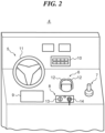
- FIG. 2 is a perspective view of a principal part of the maneuvering seat 4.
- a steering mechanism 5, a remote control unit 6, a joystick 7, a main operation unit 8, a multi function display (an MFD) 9, and a maneuvering panel 10 are located on the maneuvering seat 4.
- the steering mechanism 5 is a device for a marine vessel operator to determine a course of the marine vessel 1.
- the steering mechanism 5 includes a steering wheel 11 which can be rotatably operated.
- the marine vessel operator is able to turn the marine vessel 1 the left or the right by rotatably operating the steering wheel 11 the left or the right.
- the remote control unit 6 includes levers 12 corresponding to the outboard motors 3, respectively. By operating each lever 12, the marine vessel operator is able to switch a direction of the thrust generated by the corresponding outboard motor 3 between a forward moving direction and a backward moving direction, and adjust the output of the corresponding outboard motor 3 so as to adjust a vessel speed of the marine vessel 1.
- the joystick 7 is a control stick for the marine vessel operator to navigate the marine vessel 1.
- the outboard motor 3 works mainly according to an operation of the steering mechanism 5 and an operation of the remote control unit 6.
- the outboard motor 3 works mainly according to an operation of the joystick 7. It is possible to switch between the normal mode and the joystick mode by a change-over switch (not shown).
- the main operation unit 8 includes a main switch 13 and an engine shutoff switch 14.
- the main switch 13 (one main switch 13) is provided in common for the outboard motors 3 (respective outboard motors 3).
- the main switch 13 is an operation piece for collectively starting and collectively stopping the engines of the outboard motors 3 (the respective outboard motors 3).
- the engine shutoff switch 14 is a switch for emergency-stopping the engines of the outboard motors 3 (the respective outboard motors 3).
- the MFD 9 is, for example, a color LCD display.
- the MFD 9 functions as a display that displays various kinds of information, and also functions as a touch panel that accepts inputs from the marine vessel operator.
- FIG. 3 is a block diagram for schematically explaining a configuration of the marine vessel propulsion control system 15 mounted on the marine vessel 1 of FIG. 1 .
- the marine vessel propulsion control system 15 includes the outboard motors 3, a boat control unit (a BCU) 16 functioning as a controller, the MFD 9, a global positioning system (a GPS) 17, a compass 18, a keyless entry receiver 19, the remote control unit 6, the joystick 7, the steering mechanism 5, the maneuvering panel 10, remote control engine control units (remote control ECUs) 20, the main operation unit 8, and steering control units (SCUs) 21.
- Respective components of the marine vessel propulsion control system 15 are communicably connected to each other. It should be noted that although the marine vessel 1 is originally equipped with the three outboard motors 3, in order to avoid complicated wiring in FIG. 3 , two outboard motors 3 are drawn in FIG. 3 for convenience.
- the GPS 17 obtains the current position of the marine vessel 1 and transmits the current position of the marine vessel 1 to the BCU 16.
- the compass 18 obtains a direction (a yaw angle) of the marine vessel 1 and transmits the direction of the marine vessel 1 to the BCU 16.
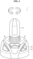
- FIG. 4 is an external view that schematically shows a configuration of the joystick 7 shown in FIG. 3 .
- the joystick 7 includes a base 22, a rod-shaped stick 23 (an operation piece) attached to the top of the base 22, and a plurality of buttons 24 provided on the base 22.
- the stick 23 is able to swing freely with respect to the base 22 so that the marine vessel operator is able to intuitively perform maneuvering of the marine vessel 1.
- the joystick mode for example, when the marine vessel operator tilts the stick 23 forward or backward, the joystick 7 emits a signal for moving the marine vessel 1 forward or backward, and when the marine vessel operator tilts the stick 23 toward the left or the right, the joystick 7 emits a signal for moving the marine vessel 1 to the left or the right.
- the stick 23 is able to be twisted (moved rotationally) with respect to the base 22 (see arrows in FIG. 4 ).
- the joystick 7 emits a signal for turning the marine vessel 1.
- the joystick 7 emits a signal for generating a thrust corresponding to a tilting amount of the stick 23.
- the signals from the joystick 7 are transmitted to each of the remote control ECUs 20 and the BCU 16.
- the marine vessel operator In the joystick mode, by operating the stick 23, the marine vessel operator is able to navigate the marine vessel 1 with a course corresponding to a tilting direction of the stick 23 and the thrust corresponding to the tilting amount of the stick 23.
- Instructions to start/end various kinds of maneuvering modes are assigned to the plurality of buttons 24 of the joystick 7, and depending on pressing down each of the plurality of buttons 24, the joystick 7 transmits an instruction signal for starting or ending a maneuvering mode corresponding to each of the plurality of buttons 24 pressed down to each of the remote control ECUs 20 and the BCU 16.
- the maneuvering modes that can be selected by each of the plurality of buttons 24 include, for example, a fixed point holding mode.
- the marine vessel operator is able to set the level of the thrust generated by the engine of each outboard motor 3 when the marine vessel operator tilts the stick 23 in the joystick mode (hereinafter, referred to as "a thrust level").
- a thrust level the level of the thrust generated by the engine of each outboard motor 3 when the marine vessel operator tilts the stick 23 in the joystick mode
- the thrust level increases, and when the marine vessel operator presses down the "-" side of the button 25, the thrust level decreases.
- the joystick 7 transmits the content of an operation input to the button 25 to the BCU 16, and the BCU 16 changes the thrust level according to the content of the operation input to the button 25.
- the maneuvering panel 10 also includes buttons similar to the plurality of buttons 24 and the button 25.
- the marine vessel operator is able to select various kinds of maneuvering modes and is also able to set the thrust level.
- the steering mechanism 5 accepts the operation with respect to the steering wheel 11 performed by the marine vessel operator, and transmits a steering angle corresponding to the accepted operation to each of the remote control ECUs 20.
- the keyless entry receiver 19 is a radio wave receiver that receives an operation input signal of an external key (not shown) as a radio wave.
- the keyless entry receiver 19 receives operation input signals of the external key to the main switch and a start/stop switch, and transmits these signals to the BCU 16 and each of the remote control ECUs 20.
- the SCU 21 is provided corresponding to each outboard motor 3, and controls a steering unit (not shown) that horizontally turns the corresponding outboard motor 3 with respect to the hull 2 of the marine vessel 1 so as to change an acting direction of the thrust of each outboard motor 3.
- the BCU 16 obtains the situation of the marine vessel 1 based on the signals transmitted from the respective components of the marine vessel propulsion control system 15, determines the magnitude of a thrust that each outboard motor 3 should generate and an acting direction of the thrust that should be taken, and transmits the result of determining to each of the remote control ECUs 20.
- the remote control ECU 20 is provided for each outboard motor 3, and controls the engine of the corresponding outboard motor 3 and the steering unit in response to the signals transmitted from the BCU 16, the steering mechanism 5, the remote control unit 6, the joystick 7, etc. so as to adjust the thrust and the acting direction of the thrust of the corresponding outboard motor 3. Therefore, in the marine vessel propulsion control system 15, by the marine vessel operator operating the steering wheel 11 of the steering mechanism 5, the joystick 7 or the levers of the remote control unit 6, it is possible to control the vessel speed and the yaw angle of the marine vessel 1.
- the marine vessel 1 when the marine vessel 1 avoids other marine vessels within a harbor or when the marine vessel 1 docks with a quay, the marine vessel 1 often moves in a lateral direction perpendicular to a front-rear direction (a keel direction) of the hull 2.
- a resultant thrust When the marine vessel 1 moves in the lateral direction, it is necessary to individually adjust the acting direction and the magnitude of the thrust of each outboard motor 3 so that a resultant force of the thrusts of the respective outboard motors 3 (hereinafter, referred to as "a resultant thrust") becomes a lateral direction thrust with respect to the marine vessel 1.
- a resultant thrust a resultant force of the thrusts of the respective outboard motors 3
- this adjustment is quite difficult for the marine vessel operator because it is necessary to make the acting direction of the thrust of one outboard motor 3 different from that of the other outboard motors 3.
- the BCU 16 when the BCU 16 detects tilting of the stick 23 of the joystick 7 toward the lateral direction performed by the marine vessel operator, the BCU 16 individually adjusts the acting direction and the magnitude of the thrust of each outboard motor 3 so as to generate the thrust for moving the marine vessel 1 in the lateral direction.
- Such adjustment of the acting direction and the magnitude of the thrust of each outboard motor 3 for moving the marine vessel 1 in the lateral direction, which is performed by the BCU 16, is generally referred to as "lateral assist".
- the BCU 16 continues to generate the resultant thrust moving the marine vessel 1 in the lateral direction perpendicular to the front-rear direction of the hull 2, which sometimes results in the marine vessel 1 moving in a direction which is different from a lateral direction initially desired by the marine vessel operator.
- a line along the lateral direction when the marine vessel operator tilts the stick 23 toward the lateral direction is set as a movement target line, and in the lateral assist, the BCU 16 controls the acting direction and the magnitude of the thrust of each outboard motor 3 so that the marine vessel 1 does not move away from the movement target line when the marine vessel 1 moves in the lateral direction.
- FIG. 5 is a view for explaining the lateral assist in the preferred embodiment. It should be noted that in FIGs. 5 , 6 , 8 , 9 , and 10 , an open arrow near the stick 23 indicates the tilting direction of the stick 23, and a dashed arrow indicates an actual moving track of the marine vessel 1. It should also be noted that in FIGs. 5 , 6 , 8 , 9 , and 10 , the state of tilting or moving rotationally of the joystick 7 in each state of the marine vessel 1 is drawn above the marine vessel 1 in each state.
- the BCU 16 sets a line along a lateral direction perpendicular to the front-rear direction of the hull 2 at that time as a movement target line 26.
- a direction of the movement target line 26 is based on the earth coordinate system and is not affected by the turning of the marine vessel 1.
- each outboard motor 3 is changed so that the three outboard motors 3 form an inverted V shape in a plan view. Also, when it is desired to move the marine vessel 1 to the right in FIG. 5 , the outboard motor 3 of the starboard and the outboard motor 3 of the center are caused to generate a backward moving direction thrust, and the outboard motor 3 of the port side is caused to generate a forward moving direction thrust.
- the BCU 16 performs correction control in the front-rear direction (first control) that changes the resultant thrust so as to eliminate a deviation in the front-rear direction of the marine vessel 1 from the movement target line 26.
- FIG. 6 is a graph for explaining a change in the resultant thrust in the correction control in the front-rear direction of the lateral assist in the preferred embodiment.
- the horizontal axis indicates a moving distance of the marine vessel 1
- the vertical axis indicates a forward and backward output ratio which is a ratio of output(s) of the outboard motor(s) 3 generating the forward moving direction thrust among a plurality of the outboard motors 3 (hereinafter, referred to as "a forward moving output”) to output(s) of the outboard motor(s) 3 generating the backward moving direction thrust among the plurality of the outboard motors 3 (hereinafter, referred to as "a backward moving output”).
- the forward and backward output ratio is calculated by the following Expression 1.
- the forward and backward output ratio the forward moving output / the backward moving output
- an initial correction ratio in FIG. 6 is a forward and backward output ratio in the case that the resultant thrust does not have a component in the front-rear direction and consists only of the thrust in the lateral direction.
- the BCU 16 makes the forward and backward output ratio higher than the initial correction ratio to move the marine vessel 1 forward and eliminate the deviation of the marine vessel 1 from the movement target line 26. Further, when the marine vessel 1 deviates forward from the movement target line 26 due to the external disturbances or the like, the BCU 16 makes the forward and backward output ratio lower than the initial correction ratio to move the marine vessel 1 backward and eliminate the deviation of the marine vessel 1 from the movement target line 26. For example, as shown in FIG.
- the BCU 16 increases the forward and backward output ratio to generate a front-rear direction component 27 (see a hatched arrow in FIG. 5 ) in the resultant thrust to suppress that the marine vessel 1 moves away from the movement target line 26.
- the forward and backward output ratio is not changed sharply, but is changed gradually as shown in FIG. 6 .
- the BCU 16 gradually increases the forward and backward output ratio, and then when the marine vessel 1 begins to move forward toward the movement target line 26, the BCU 16 gradually lowers the forward and backward output ratio.
- the BCU 16 gradually lowers the forward and backward output ratio, and then when the marine vessel 1 begins to move backward toward the movement target line 26, the BCU 16 gradually increases the forward and backward output ratio.
- the change tendency of the forward and backward output ratio is not immediately changed.
- the BCU 16 starts to lower the forward and backward output ratio after a predetermined time (see t1 in FIG. 6 ) has elapsed since the marine vessel 1 deviated backward from the movement target line 26 starts to move forward toward the movement target line 26.
- the BCU 16 starts to increase the forward and backward output ratio after a predetermined time (see t2 in FIG. 6 ) has elapsed since the marine vessel 1 deviated forward from the movement target line 26 starts to move backward toward the movement target line 26.
- the BCU 16 calculates the deviation of the marine vessel 1 from the movement target line 26 on the basis of a comparison between the current position of the marine vessel 1 in the earth coordinate system obtained by the GPS 17 and the movement target line 26 in the earth coordinate system.
- the correction control in the front-rear direction in the lateral assist is terminated, and when the tilting of the stick 23 toward the lateral direction performed by the marine vessel operator is released and the stick 23 returns to a neutral position with respect to the lateral direction, the lateral assist itself is terminated.
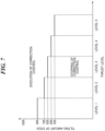
- FIG. 7 is a graph for explaining the predetermined tilting amount of the stick (hereinafter, referred to as "a tilting amount for judgment") used for judging whether or not to terminate the correction control in the front-rear direction in the lateral assist in the preferred embodiment.
- a tilting amount for judgment the predetermined tilting amount of the stick used for judging whether or not to terminate the correction control in the front-rear direction in the lateral assist in the preferred embodiment.
- the marine vessel operator since the higher the thrust level in the joystick mode, the larger the thrust generated by the engine of each outboard motor 3, when the thrust level is high, the marine vessel operator is able to easily feel moving in the lateral direction of the marine vessel 1 even if the stick 23 is not tilted so much. Furthermore, in the case that the marine vessel operator feels moving in the lateral direction of the marine vessel 1, when the marine vessel operator recognizes that the marine vessel 1 is moving in the lateral direction aimed by the marine vessel operator, that is, when the marine vessel operator recognizes that the marine vessel 1 will not move away from the movement target line 26, the marine vessel operator will feel a sense of security. That is, it is preferable that the correction control in the front-rear direction in the lateral assist is performed in the case that the marine vessel operator feels moving in the lateral direction of the marine vessel 1.
- the tilting amount for judgment is changed according to the thrust level. Specifically, the tilting amount for judgment is set lower as the thrust level is higher and the marine vessel operator is able to more easily feel moving in the lateral direction of the marine vessel 1 even if the stick 23 is not tilted so much.
- the tilting amount for judgment is set to 80% of the total tilting amount of the stick 23, and in the case that the thrust level is level 5 where the thrust generated by the engine of each outboard motor 3 is the largest, the tilting amount for judgment is set to 55% of the total tilting amount of the stick 23.
- the correction control in the front-rear direction will be terminated in the lateral assist just by returning the stick 23 slightly from the tilted state.
- the thrust level is high and the marine vessel operator does not become not to be able to feel moving in the lateral direction of the marine vessel 1 unless the stick 23 is largely returned from the tilted state
- the correction control in the front-rear direction will not be terminated in the lateral assist.
- FIG. 8 is a view for explaining moving in the front-rear direction in the lateral assist in the preferred embodiment.
- the BCU 16 When the lateral assist is being executed in response to tilting the stick 23 toward the lateral direction performed by the marine vessel operator, the BCU 16 generates the front-rear direction component 27 in the resultant thrust so that the correction control in the front-rear direction described above is executed to eliminate the deviation in the front-rear direction of the marine vessel 1 from the movement target line 26.
- the BCU 16 temporarily interrupts the correction control in the front-rear direction, and performs midway movement control (second control) that generates a forward component having a magnitude corresponding to an amount of tilting forward of the stick 23 in the resultant thrust.
- midway movement control second control
- moving in the lateral direction of the marine vessel 1 is continued.
- the marine vessel 1 moves obliquely forward (in the right obliquely upward direction in FIG. 8 ).
- the BCU 16 stores the forward and backward output ratio when the correction control in the front-rear direction is interrupted.
- the BCU 16 ends the midway movement control and terminates generating the forward component of the resultant thrust. Then, the BCU 16 sets a line along a lateral direction perpendicular to the front-rear direction of the hull 2 when the stick 23 is returned to the neutral position with respect to the front-rear direction as a new movement target line 28, and resumes the correction control in the front-rear direction so that the marine vessel 1 does not deviate from the new movement target line 28 with respect to the front-rear direction while continuing to move the marine vessel 1 in the lateral direction.
- the BCU 16 After that, the BCU 16 generates a front-rear direction component 29 in the resultant thrust so as to eliminate a deviation in the front-rear direction from the new movement target line 28.
- the BCU 16 adjusts the output of each outboard motor 3 according to the stored forward and backward output ratio, and generates the same resultant thrust as the resultant thrust when the correction control in the front-rear direction is interrupted. It should be noted that when returning the stick 23 to the neutral position with respect to the front-rear direction, the marine vessel operator also continues to tilt the stick 23 toward the lateral direction.
- FIG. 8 shows an example in which the marine vessel 1 deviates backward from the movement target line 26 and the new movement target line 28, when the marine vessel 1 deviates forward from the movement target line 26 and the new movement target line 28, the same correction control in the front-rear direction is executed.
- the marine vessel operator may lose sight of the target position existing on the movement target line 26.
- a yaw angle of the marine vessel 1 when the marine vessel operator tilts the stick 23 toward the lateral direction is set as a reference yaw angle, and in the lateral assist, the BCU 16 controls the acting direction and the magnitude of the thrust of each outboard motor 3 so that the marine vessel 1 does not deviate from the reference yaw angle when the marine vessel 1 moves in the lateral direction.
- FIG. 9 is a view for explaining control of the yaw angle of the marine vessel 1 in the lateral assist in the preferred embodiment.
- the BCU 16 sets the movement target line 26 and sets the yaw angle of the marine vessel 1 at that time as the reference yaw angle.
- the reference yaw angle is based on the earth coordinate system and is not affected by the turning of the marine vessel 1.
- the BCU 16 performs correction control in a yaw direction (third control) that changes the resultant thrust so as to eliminate a deviation in the yaw direction from the reference yaw angle.
- a yaw direction third control
- the BCU 16 performs correction control in a yaw direction (third control) that changes the resultant thrust so as to eliminate a deviation in the yaw direction from the reference yaw angle.
- the BCU 16 generates the front-rear direction component 27 in the resultant thrust so as to eliminate the deviation in the front-rear direction of the marine vessel 1.
- the BCU 16 calculates the deviation of the marine vessel 1 from the reference yaw angle on the basis of a comparison between the current yaw angle of the marine vessel 1 obtained by the compass 18 and the reference yaw angle.
- the BCU 16 temporarily interrupts the correction control in the yaw direction and the correction control in the front-rear direction, and performs midway turning control (fourth control) that generates a turning direction component having a magnitude corresponding to an amount of moving rotationally of the stick 23 in the resultant thrust.
- midway turning control fourth control
- the BCU 16 ends the midway turning control and terminates generating the turning direction component of the resultant thrust. Then, the BCU 16 sets a line along a lateral direction perpendicular to the front-rear direction of the hull 2 when the stick 23 is returned to the neutral position with respect to the yaw direction as a new movement target line 28, and sets the yaw angle of the marine vessel 1 at this time as a new reference yaw angle.
- the BCU 16 resumes the correction control in the yaw direction and the correction control in the front-rear direction (fifth control), generates a front-rear direction component 29 in the resultant thrust so as to eliminate a deviation in the front-rear direction from the new movement target line 28, and further generates a turning direction component 31 in the resultant thrust so as to eliminate a deviation in the yaw direction from the new reference yaw angle.
- FIG. 9 shows an example in which the marine vessel 1 deviates clockwise from the reference yaw angle and the new reference yaw angle, when the marine vessel 1 deviates counterclockwise from the reference yaw angle and the new reference yaw angle, the same correction control in the yaw direction is executed.
- FIG. 10 is a view for explaining a case that the midway turning control is performed for a relatively long time in the lateral assist in the preferred embodiment.
- the marine vessel 1 since moving in the lateral direction of the marine vessel 1 is continued while the midway turning control is being performed, the marine vessel 1 does not turn on the spot, but turns while moving in the lateral direction. As a result, while the marine vessel operator is rotationally moving the stick 23, the marine vessel 1 moves so as to draw a circle.
- the tilting amount toward the lateral direction of the stick 23 is equal to or more than a tilting amount for judgment
- the lateral assist not only the correction control in the front-rear direction is executed, but also the correction control in the yaw direction is executed, and on the other hand, in the case that the tilting amount toward the lateral direction of the stick 23 is less than the tilting amount for judgment, in the lateral assist, not only the correction control in the front-rear direction is terminated, but also the correction control in the yaw direction is terminated.
- the tilting amount for judgment at this time is the same as the tilting amount for judgment shown in FIG. 7 , as a result, when the thrust level is low, if the stick 23 is not largely tilted, the correction control in the yaw direction will not be executed in the lateral assist. On the other hand, when the thrust level is high, the correction control in the yaw direction will be executed in the lateral assist even if the stick 23 is not largely tilted. Conversely, when the thrust level is low, the correction control in the yaw direction will be terminated in the lateral assist just by returning the stick 23 slightly from the tilted state. On the other hand, when the thrust level is high, if the stick 23 is not largely returned from the tilted state, the correction control in the yaw direction will not be terminated in the lateral assist.
- FIG. 11 is a flowchart for explaining the flow of a processing in the lateral assist in the preferred embodiment.
- the BCU 16 judges whether or not the stick 23 is tilted toward the lateral direction, specifically, judges whether or not the tilting amount of the stick 23 exceeds the tilting amount for judgment (step S1101). In the case that the tilting amount of the stick 23 does not exceed the tilting amount for judgment, the processing returns to step S1101. On the other hand, in the case that the tilting amount of the stick 23 exceeds the tilting amount for judgment, the BCU 16 judges whether or not a precondition is satisfied (step S1102).
- the precondition in step S1102 includes, for example, whether or not the execution of the lateral assist is permitted by the MFD 9, whether or not the compass 18 is calibrated with respect to a traveling direction of the marine vessel 1, whether or not the marine vessel 1 includes two or more outboard motors 3, whether or not an error occurs in the GPS 17 or the compass 18, whether or not to shift to the joystick mode, and/or whether or not a forward speed component of the marine vessel 1 is lower than a predetermined speed.
- step S1102 the BCU 16 stores (latches) the current position of the marine vessel 1 and the current direction (the current yaw angle) of the marine vessel 1 (step S1103), sets the current yaw angle as the reference yaw angle, and sets the movement target line 26 based on the current position and the current yaw angle (step S1104).
- the BCU 16 causes the respective outboard motors 3 to generate the resultant thrust and move the marine vessel 1 in the lateral direction (step S1105), and performs the correction control in the front-rear direction and the correction control in the yaw direction while the marine vessel 1 is moving in the lateral direction (step S1106).
- the BCU 16 judges whether or not the stick 23 is tilted with respect to the front-rear direction (whether or not the stick 23 is tilted forward or backward) (step S1107).
- the BCU 16 temporarily interrupts the correction control in the front-rear direction and the correction control in the yaw direction (step S1108), stores the forward and backward output ratio at this time, and then performs the midway movement control (step S1109).
- step S1110 the BCU 16 judges whether or not tilting with respect to the front-rear direction of the stick 23 is released (whether or not the stick 23 is returned to the neutral position with respect to the front-rear direction) (step S1110). In the case that the tilting with respect to the front-rear direction of the stick 23 is not released, the processing returns to step S1110. On the other hand, in the case that the stick 23 is returned to the neutral position with respect to the front-rear direction, the processing proceeds to step S1103.
- step S1107 in the case that the stick 23 is not tilted with respect to the front-rear direction, the BCU 16 judges whether or not the stick 23 is moved rotationally (twisted) (step S1111). In the case that the stick 23 is moved rotationally (twisted) (YES in step S1111), the BCU 16 temporarily interrupts the correction control in the front-rear direction and the correction control in the yaw direction (step S1112), and performs the midway turning control (step S1113).
- step S1114 the BCU 16 judges whether or not moving rotationally of the stick 23 is released (whether or not the stick 23 is returned to the neutral position with respect to the yaw direction) (step S1114). In the case that the moving rotationally of the stick 23 is not released, the processing returns to step S1114. On the other hand, in the case that the stick 23 is returned to the neutral position with respect to the yaw direction, the processing proceeds to step S1103.
- step S1111 in the case that the stick 23 is not moved rotationally, the BCU 16 judges whether or not tilting toward the lateral direction of the stick 23 is released (step S 1115).
- step S1115 In the case that the tilting toward the lateral direction of the stick 23 is not released (NO in step S1115), more specifically, in the case that the tilting amount toward the lateral direction of the stick 23 is equal to or more than the tilting amount for judgment, the processing returns to step S1106. On the other hand, in the case that the tilting toward the lateral direction of the stick 23 is released (YES in step S1115), the BCU 16 stops moving in the lateral direction of the marine vessel 1 and ends the lateral assist.
- the BCU 16 sets the line along the lateral direction perpendicular to the front-rear direction of the hull 2 when the stick 23 is tilted toward the lateral direction as the movement target line 26, and when the marine vessel 1 moves in the lateral direction, the BCU 16 generates the front-rear direction component in the resultant thrust, which is the resultant force of the thrusts of the respective outboard motors 3, so as to suppress that the marine vessel 1 moves away from the movement target line 26.
- the marine vessel 1 moves in the lateral direction, it is possible to suppress that the marine vessel 1 deviates in the front-rear direction from the position of the marine vessel 1 when the stick 23 is tilted. Therefore, it is possible to cause the marine vessel 1 to hold the course in the lateral direction desired by the marine vessel operator.
- the BCU 16 sets the yaw angle of the marine vessel 1 when the stick 23 is tilted toward the lateral direction as the reference yaw angle, and when the marine vessel 1 moves in the lateral direction, the BCU 16 generates the turning direction component in the resultant thrust, which is the resultant force of the thrusts of the respective outboard motors 3, so that the marine vessel 1 does not deviate from the reference yaw angle.
- the marine vessel 1 moves in the lateral direction, it is possible to suppress that the marine vessel operator loses sight of the target position existing on the movement target line 26.
- the BCU 16 when the stick 23 is tilted toward the front-rear direction (forward or backward), the BCU 16 generates a front-rear direction component (a forward component or a backward component) having a magnitude corresponding to a tilting amount toward the front-rear direction of the stick 23 (an amount of tilting forward of the stick 23 or an amount of tilting backward of the stick 23) in the resultant thrust. Further, when the stick 23 is moved rotationally, the BCU 16 generates the turning direction component having the magnitude corresponding to the amount of moving rotationally of the stick 23 in the resultant thrust.
- a front-rear direction component a forward component or a backward component
- the marine vessel operator is able to easily change the direction of the movement target line by moving rotationally the stick 23, the marine vessel operator is able to intuitively change the course of the marine vessel 1, and it is possible to reduce the burden of the course change operation on the marine vessel operator.
- the marine vessel operator is able to easily instruct the execution of the lateral assist with the stick 23.
- the BCU 16 when the midway movement control ends and the correction control in the front-rear direction is resumed, the BCU 16 generates the front-rear direction component 29 when the midway movement control is started in the resultant thrust.
- the marine vessel propulsion control system 15 is applied to the marine vessel 1 including the outboard motors 3, there is no limitation on the type of the marine vessel to which the marine vessel propulsion control system 15 according to the preferred embodiment is applied, and it may be applied to a marine vessel equipped with inboard/outboard motors or inboard motors.
- Preferred embodiment may be realized by reading out a program that performs the functions of the above-described preferred embodiment from a memory or the like included in the BCU 16 and executing the program by the BCU 16.
- preferred embodiment may be realized by supplying the program that performs the functions of the above-described preferred embodiment to the marine vessel propulsion control system 15 via a network or a storage medium, and executing the supplied program by the BCU 16.
- preferred embodiment may also be realized by a circuit (for example, an ASIC) that achieves one or more functions of the BCU 16.
Landscapes
- Chemical & Material Sciences (AREA)
- Engineering & Computer Science (AREA)
- Combustion & Propulsion (AREA)
- Mechanical Engineering (AREA)
- Ocean & Marine Engineering (AREA)
- Control Of Position, Course, Altitude, Or Attitude Of Moving Bodies (AREA)
- Mechanical Control Devices (AREA)
Abstract
Description
- The present invention relates to a marine vessel and a control method for a marine vessel propulsion control system.
- For the purpose of improving operability, marine vessels that are each provided with a joystick, which is a marine vessel maneuvering mechanism separate from a steering and a remote control unit, are known. In such a marine vessel, the marine vessel moves in a direction toward which a marine vessel operator tilts the joystick, and a moving speed of the marine vessel at that time changes according to a tilting amount of the joystick (For example, see "Helm Master EX", [online], Yamaha Motor Co., Ltd., [searched on December 14, 2021], Internet <URL: https://www.yamaha-motor.co.jp/marine/lineup/outboard/helmmasterex/>).
- For example, when the marine vessel operator wants to move the marine vessel in a lateral direction perpendicular to a front-rear direction (a longitudinal direction) of a hull of the marine vessel, the marine vessel operator tilts the joystick toward the lateral direction, and the marine vessel moves in the lateral direction according to the tilting of the joystick. However, since external disturbances such as tidal currents and wind act on the hull, furthermore, since sometimes the speed of the marine vessel itself remains and this may cause the marine vessel to move in the front-rear direction during moving in the lateral direction, sometimes the marine vessel moves forward or backward while deviating from a tilting direction of the joystick. Therefore, control is performed to reduce the moving speed of the marine vessel in the front-rear direction at a point of time when the marine vessel starts to move in the lateral direction.
- However, since it takes some time for the moving speed of the marine vessel in the front-rear direction to sufficiently decrease, the marine vessel will move somewhat in the front-rear direction while moving in the lateral direction. Furthermore, since when the marine vessel receives the external disturbances during moving in the lateral direction and rotates (turns) in a yaw direction, the lateral direction with respect to the marine vessel rotates according to the turning of the marine vessel, as shown in
FIG. 12 , sometimes amarine vessel 100 moves in a direction (a direction indicated by a dashed arrow inFIG. 12 ) which is different from a lateral direction initially desired by the marine vessel operator (a direction indicated by an open arrow inFIG. 12 ). Therefore, there is room for improvement in holding the course of themarine vessel 100 in the lateral direction when the marine vessel operator tilts thejoystick 101 toward the lateral direction. - It is the object of the present invention provide a marine vessel and a control method for a marine vessel propulsion control system that are each able to cause a marine vessel to hold a course in a lateral direction desired by a marine vessel operator.
- According to the present invention said object is solved by a control method for a marine vessel propulsion control system having the features of
independent claim 1. Moreover, said object is solved by a marine vessel having the features ofindependent claim 2. Preferred embodiments are laid down in the dependent claims. - Accordingly, a marine vessel includes a plurality of propulsion devices configured such that are each able to individually control a magnitude and a direction of a thrust generated, a rod-shaped operation piece for moving the marine vessel in a tilting direction, and a controller configured or programmed to control the magnitude and the direction of the thrust generated by each of the plurality of propulsion devices so as to move the marine vessel in the tilting direction of the operation piece. When the operation piece is tilted toward a lateral direction perpendicular to a front-rear direction of the marine vessel, the controller is configured or programmed to execute first control that moves the marine vessel in the lateral direction, and causes each of the plurality of propulsion devices to generate a thrust, which eliminating a deviation in the front-rear direction from a position of the marine vessel when the operation piece is tilted, during moving of the marine vessel in the lateral direction. When the operation piece is tilted with respect to the front-rear direction of the marine vessel while the marine vessel moves in the lateral direction, the controller is configured or programmed to interrupt the first control and execute second control that causes each of the plurality of propulsion devices to generate a thrust corresponding to tilting with respect to the front-rear direction of the operation piece.
- According to another preferred embodiment, a control method for a marine vessel propulsion control system that is capable of individually controlling magnitudes and directions of thrusts generated by a plurality of propulsion devices provided on a marine vessel, includes a rod-shaped operation piece configured for control of moving the marine vessel in a tilting direction, and is configured or programmed to control the magnitude and the direction of the thrust generated by each of the plurality of propulsion devices so as to move the marine vessel in the tilting direction of the operation piece, the control method including the following steps: when the operation piece is tilted toward a lateral direction perpendicular to a front-rear direction of the marine vessel, executing first control that controls moving of the marine vessel in the lateral direction, and controls each of the plurality of propulsion devices to cause each of the plurality of propulsion devices to generate a thrust, which eliminating a deviation in the front-rear direction from a position of the marine vessel when the operation piece is tilted, during moving of the marine vessel in the lateral direction; and when the operation piece is tilted with respect to the front-rear direction of the marine vessel while the marine vessel moves in the lateral direction, interrupting the first control and executing second control that controls each of the plurality of propulsion devices to cause each of the plurality of propulsion devices to generate a thrust corresponding to tilting with respect to the front-rear direction of the operation piece.
- According to another preferred embodiment, a marine vessel includes a plurality of propulsion devices configured such that are each able to individually control a magnitude and a direction of a thrust generated, a rod-shaped operation piece for moving the marine vessel in a tilting direction, and a controller configured or programmed to control the magnitude and the direction of the thrust generated by each of the plurality of propulsion devices so as to move the marine vessel in the tilting direction of the operation piece. When the operation piece is tilted toward a lateral direction perpendicular to a front-rear direction of the marine vessel, the controller is configured or programmed to set a movement target line extending in the lateral direction, and move the marine vessel along the movement target line.
- According to the preferred embodiments, the controller moves the marine vessel in the lateral direction, and causes each of the plurality of propulsion devices to generate the thrust, which eliminating the deviation in the front-rear direction from the position of the marine vessel when the operation piece is tilted, during moving of the marine vessel in the lateral direction. Alternatively, the controller sets the movement target line extending in the lateral direction according to the tilting of the operation piece toward the lateral direction, and moves the marine vessel along the movement target line. As a result, when the marine vessel moves in the lateral direction, it is possible to suppress that the marine vessel deviates in the front-rear direction from the position of the marine vessel when the operation piece is tilted. Therefore, it is possible to cause the marine vessel to hold the course in the lateral direction desired by the marine vessel operator.
- The above and other elements, features, steps, characteristics and advantages of the present invention will become more apparent from the following detailed description of the preferred embodiments with reference to the attached drawings.
-
-
FIG. 1 is a perspective view of a marine vessel provided with a marine vessel propulsion control system according to a preferred embodiment. -
FIG. 2 is a perspective view of a principal part of a maneuvering seat of the marine vessel ofFIG. 1 . -
FIG. 3 is a block diagram for schematically explaining a configuration of the marine vessel propulsion control system mounted on the marine vessel ofFIG. 1 . -
FIG. 4 is an external view that schematically shows a configuration of a joystick shown inFIG. 3 . -
FIG. 5 is a view for explaining lateral assist in the preferred embodiment. -
FIG. 6 is a graph for explaining a change in a resultant thrust in correction control in a front-rear direction of the lateral assist in the preferred embodiment. -
FIG. 7 is a graph for explaining a predetermined tilting amount of a stick used for judging whether or not to terminate the correction control in the front-rear direction in the lateral assist in the preferred embodiment. -
FIG. 8 is a view for explaining moving in the front-rear direction in the lateral assist in the preferred embodiment. -
FIG. 9 is a view for explaining control of a yaw angle of the marine vessel in the lateral assist in the preferred embodiment. -
FIG. 10 is a view for explaining a case that midway turning control is performed for a relatively long time in the lateral assist in the preferred embodiment. -
FIG. 11 is a flowchart for explaining the flow of a processing in the lateral assist in the preferred embodiment. -
FIG. 12 is a view for explaining moving of a conventional marine vessel in a lateral direction. - Hereinafter, preferred embodiments of the present invention will be described with reference to the drawings.
-
FIG. 1 is a perspective view of a marine vessel provided with a marine vesselpropulsion control system 15 according to a preferred embodiment. Amarine vessel 1 includes ahull 2, and a plurality of, for example, threeoutboard motors 3 that function as propulsion devices and are mounted on thehull 2. It should be noted that the number of theoutboard motors 3 provided in themarine vessel 1 is not limited to three, and may be two or four or more. The threeoutboard motors 3 are mounted side by side on the stern of thehull 2. Eachoutboard motor 3 includes an engine (not shown) which is an internal combustion engine functioning as a power source, and obtains a thrust from a propeller (not shown) which is rotated by a driving force of the corresponding engine. It should be noted that eachoutboard motor 3 may include an electric motor functioning as the power source, or may include both an engine and an electric motor functioning as the power source. - In addition, in the
marine vessel 1, amaneuvering seat 4 is provided on the bow side, which is the front part of thehull 2.FIG. 2 is a perspective view of a principal part of the maneuveringseat 4. Asteering mechanism 5, aremote control unit 6, ajoystick 7, amain operation unit 8, a multi function display (an MFD) 9, and amaneuvering panel 10 are located on themaneuvering seat 4. - The
steering mechanism 5 is a device for a marine vessel operator to determine a course of themarine vessel 1. Thesteering mechanism 5 includes asteering wheel 11 which can be rotatably operated. The marine vessel operator is able to turn themarine vessel 1 the left or the right by rotatably operating thesteering wheel 11 the left or the right. Theremote control unit 6 includeslevers 12 corresponding to theoutboard motors 3, respectively. By operating eachlever 12, the marine vessel operator is able to switch a direction of the thrust generated by thecorresponding outboard motor 3 between a forward moving direction and a backward moving direction, and adjust the output of thecorresponding outboard motor 3 so as to adjust a vessel speed of themarine vessel 1. - The
joystick 7 is a control stick for the marine vessel operator to navigate themarine vessel 1. In a normal mode, theoutboard motor 3 works mainly according to an operation of thesteering mechanism 5 and an operation of theremote control unit 6. On the other hand, in a joystick mode, theoutboard motor 3 works mainly according to an operation of thejoystick 7. It is possible to switch between the normal mode and the joystick mode by a change-over switch (not shown). - The
main operation unit 8 includes amain switch 13 and anengine shutoff switch 14. The main switch 13 (one main switch 13) is provided in common for the outboard motors 3 (respective outboard motors 3). Themain switch 13 is an operation piece for collectively starting and collectively stopping the engines of the outboard motors 3 (the respective outboard motors 3). Theengine shutoff switch 14 is a switch for emergency-stopping the engines of the outboard motors 3 (the respective outboard motors 3). - The MFD 9 is, for example, a color LCD display. The MFD 9 functions as a display that displays various kinds of information, and also functions as a touch panel that accepts inputs from the marine vessel operator.
-
FIG. 3 is a block diagram for schematically explaining a configuration of the marine vesselpropulsion control system 15 mounted on themarine vessel 1 ofFIG. 1 . As shown inFIG. 3 , the marine vesselpropulsion control system 15 includes theoutboard motors 3, a boat control unit (a BCU) 16 functioning as a controller, theMFD 9, a global positioning system (a GPS) 17, acompass 18, akeyless entry receiver 19, theremote control unit 6, thejoystick 7, thesteering mechanism 5, themaneuvering panel 10, remote control engine control units (remote control ECUs) 20, themain operation unit 8, and steering control units (SCUs) 21. Respective components of the marine vesselpropulsion control system 15 are communicably connected to each other. It should be noted that although themarine vessel 1 is originally equipped with the threeoutboard motors 3, in order to avoid complicated wiring inFIG. 3 , twooutboard motors 3 are drawn inFIG. 3 for convenience. - The
GPS 17 obtains the current position of themarine vessel 1 and transmits the current position of themarine vessel 1 to theBCU 16. Thecompass 18 obtains a direction (a yaw angle) of themarine vessel 1 and transmits the direction of themarine vessel 1 to theBCU 16. -
FIG. 4 is an external view that schematically shows a configuration of thejoystick 7 shown inFIG. 3 . As shown inFIG. 4 , thejoystick 7 includes abase 22, a rod-shaped stick 23 (an operation piece) attached to the top of thebase 22, and a plurality ofbuttons 24 provided on thebase 22. - The
stick 23 is able to swing freely with respect to the base 22 so that the marine vessel operator is able to intuitively perform maneuvering of themarine vessel 1. In the joystick mode, for example, when the marine vessel operator tilts thestick 23 forward or backward, thejoystick 7 emits a signal for moving themarine vessel 1 forward or backward, and when the marine vessel operator tilts thestick 23 toward the left or the right, thejoystick 7 emits a signal for moving themarine vessel 1 to the left or the right. In addition, thestick 23 is able to be twisted (moved rotationally) with respect to the base 22 (see arrows inFIG. 4 ). When the marine vessel operator twists thestick 23, thejoystick 7 emits a signal for turning themarine vessel 1. Furthermore, thejoystick 7 emits a signal for generating a thrust corresponding to a tilting amount of thestick 23. The signals from thejoystick 7 are transmitted to each of theremote control ECUs 20 and theBCU 16. - In the joystick mode, by operating the
stick 23, the marine vessel operator is able to navigate themarine vessel 1 with a course corresponding to a tilting direction of thestick 23 and the thrust corresponding to the tilting amount of thestick 23. - Instructions to start/end various kinds of maneuvering modes are assigned to the plurality of
buttons 24 of thejoystick 7, and depending on pressing down each of the plurality ofbuttons 24, thejoystick 7 transmits an instruction signal for starting or ending a maneuvering mode corresponding to each of the plurality ofbuttons 24 pressed down to each of theremote control ECUs 20 and theBCU 16. The maneuvering modes that can be selected by each of the plurality ofbuttons 24 include, for example, a fixed point holding mode. - In addition, by using the
joystick 7, the marine vessel operator is able to set the level of the thrust generated by the engine of eachoutboard motor 3 when the marine vessel operator tilts thestick 23 in the joystick mode (hereinafter, referred to as "a thrust level"). Specifically, when the marine vessel operator presses down the "+" side of abutton 25 provided on thebase 22, the thrust level increases, and when the marine vessel operator presses down the "-" side of thebutton 25, the thrust level decreases. Thejoystick 7 transmits the content of an operation input to thebutton 25 to theBCU 16, and theBCU 16 changes the thrust level according to the content of the operation input to thebutton 25. - It should be noted that the
maneuvering panel 10 also includes buttons similar to the plurality ofbuttons 24 and thebutton 25. By using themaneuvering panel 10, the marine vessel operator is able to select various kinds of maneuvering modes and is also able to set the thrust level. - Returning to
FIG. 3 , thesteering mechanism 5 accepts the operation with respect to thesteering wheel 11 performed by the marine vessel operator, and transmits a steering angle corresponding to the accepted operation to each of theremote control ECUs 20. Thekeyless entry receiver 19 is a radio wave receiver that receives an operation input signal of an external key (not shown) as a radio wave. For example, thekeyless entry receiver 19 receives operation input signals of the external key to the main switch and a start/stop switch, and transmits these signals to theBCU 16 and each of theremote control ECUs 20. - The
SCU 21 is provided corresponding to eachoutboard motor 3, and controls a steering unit (not shown) that horizontally turns the correspondingoutboard motor 3 with respect to thehull 2 of themarine vessel 1 so as to change an acting direction of the thrust of eachoutboard motor 3. - The
BCU 16 obtains the situation of themarine vessel 1 based on the signals transmitted from the respective components of the marine vesselpropulsion control system 15, determines the magnitude of a thrust that eachoutboard motor 3 should generate and an acting direction of the thrust that should be taken, and transmits the result of determining to each of theremote control ECUs 20. Theremote control ECU 20 is provided for eachoutboard motor 3, and controls the engine of the correspondingoutboard motor 3 and the steering unit in response to the signals transmitted from theBCU 16, thesteering mechanism 5, theremote control unit 6, thejoystick 7, etc. so as to adjust the thrust and the acting direction of the thrust of the correspondingoutboard motor 3. Therefore, in the marine vesselpropulsion control system 15, by the marine vessel operator operating thesteering wheel 11 of thesteering mechanism 5, thejoystick 7 or the levers of theremote control unit 6, it is possible to control the vessel speed and the yaw angle of themarine vessel 1. - By the way, when the
marine vessel 1 avoids other marine vessels within a harbor or when themarine vessel 1 docks with a quay, themarine vessel 1 often moves in a lateral direction perpendicular to a front-rear direction (a keel direction) of thehull 2. - When the
marine vessel 1 moves in the lateral direction, it is necessary to individually adjust the acting direction and the magnitude of the thrust of eachoutboard motor 3 so that a resultant force of the thrusts of the respective outboard motors 3 (hereinafter, referred to as "a resultant thrust") becomes a lateral direction thrust with respect to themarine vessel 1. However, this adjustment is quite difficult for the marine vessel operator because it is necessary to make the acting direction of the thrust of oneoutboard motor 3 different from that of the otheroutboard motors 3. Therefore, in general, when theBCU 16 detects tilting of thestick 23 of thejoystick 7 toward the lateral direction performed by the marine vessel operator, theBCU 16 individually adjusts the acting direction and the magnitude of the thrust of eachoutboard motor 3 so as to generate the thrust for moving themarine vessel 1 in the lateral direction. Such adjustment of the acting direction and the magnitude of the thrust of eachoutboard motor 3 for moving themarine vessel 1 in the lateral direction, which is performed by theBCU 16, is generally referred to as "lateral assist". - On the other hand, during moving of the
marine vessel 1 in the lateral direction, since the external disturbances such as tidal currents and wind act on thehull 2, sometimes the yaw angle of themarine vessel 1 changes and the lateral direction perpendicular to the front-rear direction of thehull 2 rotates, and as a result, the lateral direction perpendicular to the front-rear direction of thehull 2 becomes deviating from a lateral direction when the marine vessel operator tilts thestick 23 toward the lateral direction. In addition, in the lateral assist, theBCU 16 continues to generate the resultant thrust moving themarine vessel 1 in the lateral direction perpendicular to the front-rear direction of thehull 2, which sometimes results in themarine vessel 1 moving in a direction which is different from a lateral direction initially desired by the marine vessel operator. - In the preferred embodiment, in order to deal with this issue, a line along the lateral direction when the marine vessel operator tilts the
stick 23 toward the lateral direction is set as a movement target line, and in the lateral assist, theBCU 16 controls the acting direction and the magnitude of the thrust of eachoutboard motor 3 so that themarine vessel 1 does not move away from the movement target line when themarine vessel 1 moves in the lateral direction. -
FIG. 5 is a view for explaining the lateral assist in the preferred embodiment. It should be noted that inFIGs. 5 ,6 ,8 ,9 , and10 , an open arrow near thestick 23 indicates the tilting direction of thestick 23, and a dashed arrow indicates an actual moving track of themarine vessel 1. It should also be noted that inFIGs. 5 ,6 ,8 ,9 , and10 , the state of tilting or moving rotationally of thejoystick 7 in each state of themarine vessel 1 is drawn above themarine vessel 1 in each state. - As shown in
FIG. 5 , first, when the marine vessel operator tilts thestick 23 of thejoystick 7 toward the lateral direction, theBCU 16 sets a line along a lateral direction perpendicular to the front-rear direction of thehull 2 at that time as amovement target line 26. A direction of themovement target line 26 is based on the earth coordinate system and is not affected by the turning of themarine vessel 1. - After that, while the marine vessel operator continues to tilt the
stick 23 toward the lateral direction, although theBCU 16 continues to generate the resultant thrust for moving themarine vessel 1 in the lateral direction, at this time, the orientation of eachoutboard motor 3 is changed so that the threeoutboard motors 3 form an inverted V shape in a plan view. Also, when it is desired to move themarine vessel 1 to the right inFIG. 5 , theoutboard motor 3 of the starboard and theoutboard motor 3 of the center are caused to generate a backward moving direction thrust, and theoutboard motor 3 of the port side is caused to generate a forward moving direction thrust. - Then, when the
marine vessel 1 deviates in the front-rear direction from themovement target line 26 while moving in the lateral direction, theBCU 16 performs correction control in the front-rear direction (first control) that changes the resultant thrust so as to eliminate a deviation in the front-rear direction of themarine vessel 1 from themovement target line 26. -
FIG. 6 is a graph for explaining a change in the resultant thrust in the correction control in the front-rear direction of the lateral assist in the preferred embodiment. InFIG. 6 , the horizontal axis indicates a moving distance of themarine vessel 1, and the vertical axis indicates a forward and backward output ratio which is a ratio of output(s) of the outboard motor(s) 3 generating the forward moving direction thrust among a plurality of the outboard motors 3 (hereinafter, referred to as "a forward moving output") to output(s) of the outboard motor(s) 3 generating the backward moving direction thrust among the plurality of the outboard motors 3 (hereinafter, referred to as "a backward moving output"). The forward and backward output ratio is calculated by the followingExpression 1.
- Furthermore, an initial correction ratio in
FIG. 6 is a forward and backward output ratio in the case that the resultant thrust does not have a component in the front-rear direction and consists only of the thrust in the lateral direction. - As shown in
FIG. 6 , while themarine vessel 1 is moving in the lateral direction, when themarine vessel 1 deviates backward from themovement target line 26 due to the external disturbances or the like, theBCU 16 makes the forward and backward output ratio higher than the initial correction ratio to move themarine vessel 1 forward and eliminate the deviation of themarine vessel 1 from themovement target line 26. Further, when themarine vessel 1 deviates forward from themovement target line 26 due to the external disturbances or the like, theBCU 16 makes the forward and backward output ratio lower than the initial correction ratio to move themarine vessel 1 backward and eliminate the deviation of themarine vessel 1 from themovement target line 26. For example, as shown inFIG. 5 , while themarine vessel 1 is moving in the lateral direction, when themarine vessel 1 deviates backward from themovement target line 26, theBCU 16 increases the forward and backward output ratio to generate a front-rear direction component 27 (see a hatched arrow inFIG. 5 ) in the resultant thrust to suppress that themarine vessel 1 moves away from themovement target line 26. - It should be noted that in order to avoid that the
marine vessel 1 suddenly moves forward or backward, the forward and backward output ratio is not changed sharply, but is changed gradually as shown inFIG. 6 . Specifically, when themarine vessel 1 begins to deviate backward from themovement target line 26, theBCU 16 gradually increases the forward and backward output ratio, and then when themarine vessel 1 begins to move forward toward themovement target line 26, theBCU 16 gradually lowers the forward and backward output ratio. In addition, when themarine vessel 1 begins to deviate forward from themovement target line 26, theBCU 16 gradually lowers the forward and backward output ratio, and then when themarine vessel 1 begins to move backward toward themovement target line 26, theBCU 16 gradually increases the forward and backward output ratio. - It should be noted that in order to reliably return the
marine vessel 1 toward themovement target line 26, in the preferred embodiment, even in the case that themarine vessel 1 stops deviating from themovement target line 26 and begins to move toward themovement target line 26, the change tendency of the forward and backward output ratio is not immediately changed. Specifically, theBCU 16 starts to lower the forward and backward output ratio after a predetermined time (see t1 inFIG. 6 ) has elapsed since themarine vessel 1 deviated backward from themovement target line 26 starts to move forward toward themovement target line 26. In addition, theBCU 16 starts to increase the forward and backward output ratio after a predetermined time (see t2 inFIG. 6 ) has elapsed since themarine vessel 1 deviated forward from themovement target line 26 starts to move backward toward themovement target line 26. - In the preferred embodiment, the
BCU 16 calculates the deviation of themarine vessel 1 from themovement target line 26 on the basis of a comparison between the current position of themarine vessel 1 in the earth coordinate system obtained by theGPS 17 and themovement target line 26 in the earth coordinate system. - Also, in order for the
BCU 16 to execute the lateral assist ofFIG. 5 , although it is necessary for the marine vessel operator to tilt thestick 23 toward the lateral direction, since it is difficult for the marine vessel operator to accurately tilt thestick 23 toward the lateral direction in themarine vessel 1 which is shaken by the influence of waves and wind, a certain degree of an allowable range for tilting toward the lateral direction is provided. Specifically, as shown in the upper left ofFIG. 5 , when thestick 23 is tilted toward a range (see hatching inFIG. 5 ) sandwiched between directions moved rotationally by predetermined angles (θ1 and θ2 inFIG. 5 ) clockwise and counterclockwise respectively from the lateral direction indicated by a one-dot chain line, theBCU 16 executes the lateral assist ofFIG. 5 . - Furthermore, when the tilting amount toward the lateral direction of the
stick 23 is less than a predetermined tilting amount, the correction control in the front-rear direction in the lateral assist is terminated, and when the tilting of thestick 23 toward the lateral direction performed by the marine vessel operator is released and thestick 23 returns to a neutral position with respect to the lateral direction, the lateral assist itself is terminated. -
FIG. 7 is a graph for explaining the predetermined tilting amount of the stick (hereinafter, referred to as "a tilting amount for judgment") used for judging whether or not to terminate the correction control in the front-rear direction in the lateral assist in the preferred embodiment. In the preferred embodiment, in the case that the tilting amount toward the lateral direction of thestick 23 is equal to or more than the tilting amount for judgment, the correction control in the front-rear direction is executed in the lateral assist, and on the other hand, in the case that the tilting amount toward the lateral direction of thestick 23 is less than the tilting amount for judgment, the correction control in the front-rear direction is terminated in the lateral assist. - By the way, since the higher the thrust level in the joystick mode, the larger the thrust generated by the engine of each
outboard motor 3, when the thrust level is high, the marine vessel operator is able to easily feel moving in the lateral direction of themarine vessel 1 even if thestick 23 is not tilted so much. Furthermore, in the case that the marine vessel operator feels moving in the lateral direction of themarine vessel 1, when the marine vessel operator recognizes that themarine vessel 1 is moving in the lateral direction aimed by the marine vessel operator, that is, when the marine vessel operator recognizes that themarine vessel 1 will not move away from themovement target line 26, the marine vessel operator will feel a sense of security. That is, it is preferable that the correction control in the front-rear direction in the lateral assist is performed in the case that the marine vessel operator feels moving in the lateral direction of themarine vessel 1. - Accordingly, in the preferred embodiment, the tilting amount for judgment is changed according to the thrust level. Specifically, the tilting amount for judgment is set lower as the thrust level is higher and the marine vessel operator is able to more easily feel moving in the lateral direction of the
marine vessel 1 even if thestick 23 is not tilted so much. For example, as shown inFIG. 7 , in the case that the thrust level islevel 1 where the thrust generated by the engine of eachoutboard motor 3 is the smallest, the tilting amount for judgment is set to 80% of the total tilting amount of thestick 23, and in the case that the thrust level islevel 5 where the thrust generated by the engine of eachoutboard motor 3 is the largest, the tilting amount for judgment is set to 55% of the total tilting amount of thestick 23. - As a result, in the case that the thrust level is low and the marine vessel operator is not able to feel moving in the lateral direction of the
marine vessel 1 unless thestick 23 is largely tilted, if thestick 23 is not largely tilted, the correction control in the front-rear direction will not be executed in the lateral assist. On the other hand, in the case that the thrust level is high and the marine vessel operator is able to feel moving in the lateral direction of themarine vessel 1 even if thestick 23 is not largely tilted, the correction control in the front-rear direction will be executed in the lateral assist even if thestick 23 is not largely tilted. Conversely, in the case that the thrust level is low and the marine vessel operator becomes not to be able to feel moving in the lateral direction of themarine vessel 1 when thestick 23 is slightly returned from the tilted state, the correction control in the front-rear direction will be terminated in the lateral assist just by returning thestick 23 slightly from the tilted state. On the other hand, in the case that the thrust level is high and the marine vessel operator does not become not to be able to feel moving in the lateral direction of themarine vessel 1 unless thestick 23 is largely returned from the tilted state, if thestick 23 is not largely returned from the tilted state, the correction control in the front-rear direction will not be terminated in the lateral assist. - Further, when the lateral assist of
FIG. 5 is executed and themarine vessel 1 moves in the lateral direction, there are times when it is desired to actively move themarine vessel 1 in the front-rear direction. In particular, when a beginner navigates themarine vessel 1, since sometimes themovement target line 26 set when thestick 23 is first tilted toward the lateral direction deviates from the target position, there is a demand to actively move themarine vessel 1 in the front-rear direction when themarine vessel 1 moves in the lateral direction. In the preferred embodiment, in response to this demand, the operation of tilting thestick 23 toward the front-rear direction performed by the marine vessel operator is accepted during execution of the lateral assist. -
FIG. 8 is a view for explaining moving in the front-rear direction in the lateral assist in the preferred embodiment. When the lateral assist is being executed in response to tilting thestick 23 toward the lateral direction performed by the marine vessel operator, theBCU 16 generates the front-rear direction component 27 in the resultant thrust so that the correction control in the front-rear direction described above is executed to eliminate the deviation in the front-rear direction of themarine vessel 1 from themovement target line 26. - After that, when the marine vessel operator further tilts the
stick 23 toward the front-rear direction of themarine vessel 1 while tilting thestick 23 toward the lateral direction, for example, when the marine vessel operator further tilts thestick 23 forward (see the open arrow pointing up inFIG. 8 ) while tilting thestick 23 toward the lateral direction, theBCU 16 temporarily interrupts the correction control in the front-rear direction, and performs midway movement control (second control) that generates a forward component having a magnitude corresponding to an amount of tilting forward of thestick 23 in the resultant thrust. At this time as well, moving in the lateral direction of themarine vessel 1 is continued. As a result, themarine vessel 1 moves obliquely forward (in the right obliquely upward direction inFIG. 8 ). In addition, theBCU 16 stores the forward and backward output ratio when the correction control in the front-rear direction is interrupted. - Next, when the marine vessel operator releases the tilting forward of the
stick 23 and returns thestick 23 to the neutral position with respect to the front-rear direction, theBCU 16 ends the midway movement control and terminates generating the forward component of the resultant thrust. Then, theBCU 16 sets a line along a lateral direction perpendicular to the front-rear direction of thehull 2 when thestick 23 is returned to the neutral position with respect to the front-rear direction as a newmovement target line 28, and resumes the correction control in the front-rear direction so that themarine vessel 1 does not deviate from the newmovement target line 28 with respect to the front-rear direction while continuing to move themarine vessel 1 in the lateral direction. After that, theBCU 16 generates a front-rear direction component 29 in the resultant thrust so as to eliminate a deviation in the front-rear direction from the newmovement target line 28. In addition, when theBCU 16 resumes the correction control in the front-rear direction, first, theBCU 16 adjusts the output of eachoutboard motor 3 according to the stored forward and backward output ratio, and generates the same resultant thrust as the resultant thrust when the correction control in the front-rear direction is interrupted. It should be noted that when returning thestick 23 to the neutral position with respect to the front-rear direction, the marine vessel operator also continues to tilt thestick 23 toward the lateral direction. - Although
FIG. 8 shows an example in which themarine vessel 1 deviates backward from themovement target line 26 and the newmovement target line 28, when themarine vessel 1 deviates forward from themovement target line 26 and the newmovement target line 28, the same correction control in the front-rear direction is executed. - Further, as described above, during moving of the
marine vessel 1 in the lateral direction, since the external disturbances such as tidal currents and wind act on thehull 2, sometimes the yaw angle of themarine vessel 1 changes (themarine vessel 1 turns). In this case, sometimes the marine vessel operator's line of sight deviates from themovement target line 26, and the marine vessel operator may lose sight of the target position existing on themovement target line 26. - In the preferred embodiment, in order to deal with this issue, a yaw angle of the
marine vessel 1 when the marine vessel operator tilts thestick 23 toward the lateral direction is set as a reference yaw angle, and in the lateral assist, theBCU 16 controls the acting direction and the magnitude of the thrust of eachoutboard motor 3 so that themarine vessel 1 does not deviate from the reference yaw angle when themarine vessel 1 moves in the lateral direction. -
FIG. 9 is a view for explaining control of the yaw angle of themarine vessel 1 in the lateral assist in the preferred embodiment. - As shown in
FIG. 9 , first, when the marine vessel operator tilts thestick 23 of thejoystick 7 toward the lateral direction, theBCU 16 sets themovement target line 26 and sets the yaw angle of themarine vessel 1 at that time as the reference yaw angle. The reference yaw angle is based on the earth coordinate system and is not affected by the turning of themarine vessel 1. - After that, when the yaw angle of the
marine vessel 1 deviates from the reference yaw angle while the lateral assist is being executed and themarine vessel 1 is moving in the lateral direction, theBCU 16 performs correction control in a yaw direction (third control) that changes the resultant thrust so as to eliminate a deviation in the yaw direction from the reference yaw angle. Specifically, by changing the forward and backward output ratio described above and the acting direction of the thrust of eachoutboard motor 3, generating a turning direction component 30 (a turning force) in the resultant thrust, and turning themarine vessel 1, the deviation in the yaw direction from the reference yaw angle is eliminated. - Further, while the
marine vessel 1 is moving in the lateral direction, when not only the correction control in the yaw direction is executed, but also the correction control in the front-rear direction described above is executed, and themarine vessel 1 deviates from themovement target line 26 with respect to the front-rear direction, theBCU 16 generates the front-rear direction component 27 in the resultant thrust so as to eliminate the deviation in the front-rear direction of themarine vessel 1. - In the preferred embodiment, the
BCU 16 calculates the deviation of themarine vessel 1 from the reference yaw angle on the basis of a comparison between the current yaw angle of themarine vessel 1 obtained by thecompass 18 and the reference yaw angle. - Further, when the lateral assist of
FIG. 5 is executed and themarine vessel 1 moves in the lateral direction, there are times when it is desired to actively turn themarine vessel 1. In the preferred embodiment, in response to this, the operation of moving rotationally thestick 23 performed by the marine vessel operator is accepted during the execution of the lateral assist. - As shown in
FIG. 9 , in the case that themarine vessel 1 moves in the lateral direction in the lateral assist, when the marine vessel operator twists (moves rotationally) thestick 23 while tilting thestick 23 toward the lateral direction, for example, when the marine vessel operator moves rotationally thestick 23 clockwise (see the clockwise open arrow inFIG. 9 ), theBCU 16 temporarily interrupts the correction control in the yaw direction and the correction control in the front-rear direction, and performs midway turning control (fourth control) that generates a turning direction component having a magnitude corresponding to an amount of moving rotationally of thestick 23 in the resultant thrust. At this time as well, moving in the lateral direction of themarine vessel 1 is continued. As a result, themarine vessel 1 turns while moving in the lateral direction. - Next, when the marine vessel operator releases the moving rotationally of the
stick 23 and returns thestick 23 to the neutral position with respect to the yaw direction, theBCU 16 ends the midway turning control and terminates generating the turning direction component of the resultant thrust. Then, theBCU 16 sets a line along a lateral direction perpendicular to the front-rear direction of thehull 2 when thestick 23 is returned to the neutral position with respect to the yaw direction as a newmovement target line 28, and sets the yaw angle of themarine vessel 1 at this time as a new reference yaw angle. - As shown in
FIG. 9 , since the newmovement target line 28 is rotationally moved with respect to themovement target line 26 by the yaw angle at which themarine vessel 1 turns in the midway turning control, it is possible to easily change the direction of the movement target line by the midway turning control. - After that, the
BCU 16 resumes the correction control in the yaw direction and the correction control in the front-rear direction (fifth control), generates a front-rear direction component 29 in the resultant thrust so as to eliminate a deviation in the front-rear direction from the newmovement target line 28, and further generates a turningdirection component 31 in the resultant thrust so as to eliminate a deviation in the yaw direction from the new reference yaw angle. - Although
FIG. 9 shows an example in which themarine vessel 1 deviates clockwise from the reference yaw angle and the new reference yaw angle, when themarine vessel 1 deviates counterclockwise from the reference yaw angle and the new reference yaw angle, the same correction control in the yaw direction is executed. -
FIG. 10 is a view for explaining a case that the midway turning control is performed for a relatively long time in the lateral assist in the preferred embodiment. - As described above, since moving in the lateral direction of the
marine vessel 1 is continued while the midway turning control is being performed, themarine vessel 1 does not turn on the spot, but turns while moving in the lateral direction. As a result, while the marine vessel operator is rotationally moving thestick 23, themarine vessel 1 moves so as to draw a circle. - Furthermore, in the preferred embodiment, in the case that the tilting amount toward the lateral direction of the
stick 23 is equal to or more than a tilting amount for judgment, in the lateral assist, not only the correction control in the front-rear direction is executed, but also the correction control in the yaw direction is executed, and on the other hand, in the case that the tilting amount toward the lateral direction of thestick 23 is less than the tilting amount for judgment, in the lateral assist, not only the correction control in the front-rear direction is terminated, but also the correction control in the yaw direction is terminated. - The tilting amount for judgment at this time is the same as the tilting amount for judgment shown in
FIG. 7 , as a result, when the thrust level is low, if thestick 23 is not largely tilted, the correction control in the yaw direction will not be executed in the lateral assist. On the other hand, when the thrust level is high, the correction control in the yaw direction will be executed in the lateral assist even if thestick 23 is not largely tilted. Conversely, when the thrust level is low, the correction control in the yaw direction will be terminated in the lateral assist just by returning thestick 23 slightly from the tilted state. On the other hand, when the thrust level is high, if thestick 23 is not largely returned from the tilted state, the correction control in the yaw direction will not be terminated in the lateral assist. -
FIG. 11 is a flowchart for explaining the flow of a processing in the lateral assist in the preferred embodiment. - As shown in
FIG. 11 , first, theBCU 16 judges whether or not thestick 23 is tilted toward the lateral direction, specifically, judges whether or not the tilting amount of thestick 23 exceeds the tilting amount for judgment (step S1101). In the case that the tilting amount of thestick 23 does not exceed the tilting amount for judgment, the processing returns to step S1101. On the other hand, in the case that the tilting amount of thestick 23 exceeds the tilting amount for judgment, theBCU 16 judges whether or not a precondition is satisfied (step S1102). - The precondition in step S1102 includes, for example, whether or not the execution of the lateral assist is permitted by the
MFD 9, whether or not thecompass 18 is calibrated with respect to a traveling direction of themarine vessel 1, whether or not themarine vessel 1 includes two or moreoutboard motors 3, whether or not an error occurs in theGPS 17 or thecompass 18, whether or not to shift to the joystick mode, and/or whether or not a forward speed component of themarine vessel 1 is lower than a predetermined speed. - In the case that the precondition is not satisfied, the processing returns to step S1102. On the other hand, in the case that the precondition is satisfied (YES in step S1102), the
BCU 16 stores (latches) the current position of themarine vessel 1 and the current direction (the current yaw angle) of the marine vessel 1 (step S1103), sets the current yaw angle as the reference yaw angle, and sets themovement target line 26 based on the current position and the current yaw angle (step S1104). - Next, the
BCU 16 causes the respectiveoutboard motors 3 to generate the resultant thrust and move themarine vessel 1 in the lateral direction (step S1105), and performs the correction control in the front-rear direction and the correction control in the yaw direction while themarine vessel 1 is moving in the lateral direction (step S1106). - After that, the
BCU 16 judges whether or not thestick 23 is tilted with respect to the front-rear direction (whether or not thestick 23 is tilted forward or backward) (step S1107). In the case that thestick 23 is tilted with respect to the front-rear direction (YES in step S1107), theBCU 16 temporarily interrupts the correction control in the front-rear direction and the correction control in the yaw direction (step S1108), stores the forward and backward output ratio at this time, and then performs the midway movement control (step S1109). - Next, the
BCU 16 judges whether or not tilting with respect to the front-rear direction of thestick 23 is released (whether or not thestick 23 is returned to the neutral position with respect to the front-rear direction) (step S1110). In the case that the tilting with respect to the front-rear direction of thestick 23 is not released, the processing returns to step S1110. On the other hand, in the case that thestick 23 is returned to the neutral position with respect to the front-rear direction, the processing proceeds to step S1103. - In step S1107, in the case that the
stick 23 is not tilted with respect to the front-rear direction, theBCU 16 judges whether or not thestick 23 is moved rotationally (twisted) (step S1111). In the case that thestick 23 is moved rotationally (twisted) (YES in step S1111), theBCU 16 temporarily interrupts the correction control in the front-rear direction and the correction control in the yaw direction (step S1112), and performs the midway turning control (step S1113). - Next, the
BCU 16 judges whether or not moving rotationally of thestick 23 is released (whether or not thestick 23 is returned to the neutral position with respect to the yaw direction) (step S1114). In the case that the moving rotationally of thestick 23 is not released, the processing returns to step S1114. On the other hand, in the case that thestick 23 is returned to the neutral position with respect to the yaw direction, the processing proceeds to step S1103. - In step S1111, in the case that the
stick 23 is not moved rotationally, theBCU 16 judges whether or not tilting toward the lateral direction of thestick 23 is released (step S 1115). - In the case that the tilting toward the lateral direction of the
stick 23 is not released (NO in step S1115), more specifically, in the case that the tilting amount toward the lateral direction of thestick 23 is equal to or more than the tilting amount for judgment, the processing returns to step S1106. On the other hand, in the case that the tilting toward the lateral direction of thestick 23 is released (YES in step S1115), theBCU 16 stops moving in the lateral direction of themarine vessel 1 and ends the lateral assist. - According to the preferred embodiment, in the lateral assist, the
BCU 16 sets the line along the lateral direction perpendicular to the front-rear direction of thehull 2 when thestick 23 is tilted toward the lateral direction as themovement target line 26, and when themarine vessel 1 moves in the lateral direction, theBCU 16 generates the front-rear direction component in the resultant thrust, which is the resultant force of the thrusts of the respectiveoutboard motors 3, so as to suppress that themarine vessel 1 moves away from themovement target line 26. As a result, when themarine vessel 1 moves in the lateral direction, it is possible to suppress that themarine vessel 1 deviates in the front-rear direction from the position of themarine vessel 1 when thestick 23 is tilted. Therefore, it is possible to cause themarine vessel 1 to hold the course in the lateral direction desired by the marine vessel operator. - In addition, in the preferred embodiment, in the lateral assist, the
BCU 16 sets the yaw angle of themarine vessel 1 when thestick 23 is tilted toward the lateral direction as the reference yaw angle, and when themarine vessel 1 moves in the lateral direction, theBCU 16 generates the turning direction component in the resultant thrust, which is the resultant force of the thrusts of the respectiveoutboard motors 3, so that themarine vessel 1 does not deviate from the reference yaw angle. As a result, when themarine vessel 1 moves in the lateral direction, it is possible to suppress that the marine vessel operator loses sight of the target position existing on themovement target line 26. - Moreover, in the preferred embodiment, in the case that the
marine vessel 1 moves in the lateral direction in the lateral assist, when thestick 23 is tilted toward the front-rear direction (forward or backward), theBCU 16 generates a front-rear direction component (a forward component or a backward component) having a magnitude corresponding to a tilting amount toward the front-rear direction of the stick 23 (an amount of tilting forward of thestick 23 or an amount of tilting backward of the stick 23) in the resultant thrust. Further, when thestick 23 is moved rotationally, theBCU 16 generates the turning direction component having the magnitude corresponding to the amount of moving rotationally of thestick 23 in the resultant thrust. As a result, it is possible to correct the moving direction of themarine vessel 1 even during the execution of the lateral assist, and it is possible to suppress that the marine vessel operator feels difficulty in maneuvering the marine vessel. In particular, since the marine vessel operator is able to easily change the direction of the movement target line by moving rotationally thestick 23, the marine vessel operator is able to intuitively change the course of themarine vessel 1, and it is possible to reduce the burden of the course change operation on the marine vessel operator. - Moreover, in the preferred embodiment, since the allowable range is provided for the tilting toward the lateral direction of the
stick 23 for executing the lateral assist, the marine vessel operator is able to easily instruct the execution of the lateral assist with thestick 23. - Moreover, in the preferred embodiment, in the lateral assist, when the midway movement control ends and the correction control in the front-rear direction is resumed, the
BCU 16 generates the front-rear direction component 29 when the midway movement control is started in the resultant thrust. As a result, even in the case that similar external disturbances act on themarine vessel 1 before and after the midway movement control, it is possible to suppress that immediately after the correction control in the front-rear direction is resumed, themarine vessel 1 moves far away from the newmovement target line 28. - Although the marine vessel
propulsion control system 15 according to the preferred embodiment is applied to themarine vessel 1 including theoutboard motors 3, there is no limitation on the type of the marine vessel to which the marine vesselpropulsion control system 15 according to the preferred embodiment is applied, and it may be applied to a marine vessel equipped with inboard/outboard motors or inboard motors. - Preferred embodiment may be realized by reading out a program that performs the functions of the above-described preferred embodiment from a memory or the like included in the
BCU 16 and executing the program by theBCU 16. Alternatively, preferred embodiment may be realized by supplying the program that performs the functions of the above-described preferred embodiment to the marine vesselpropulsion control system 15 via a network or a storage medium, and executing the supplied program by theBCU 16. Furthermore, preferred embodiment may also be realized by a circuit (for example, an ASIC) that achieves one or more functions of theBCU 16.
Claims (16)
- A control method for a marine vessel (1) propulsion control system that is capable of individually controlling magnitudes and directions of thrusts generated by a plurality of propulsion devices (3) provided on a marine vessel (1), comprises a rod-shaped operation piece (23) configured for control of moving the marine vessel (1) in a tilting direction, and is configured or programmed to control the magnitude and the direction of the thrust generated by each of the plurality of propulsion devices (3) so as to move the marine vessel (1) in the tilting direction of the operation piece (23),
the control method comprising the following steps:when the operation piece (23) is tilted toward a lateral direction perpendicular to a front-rear direction of the marine vessel (1), executing first control that controls moving of the marine vessel (1) in the lateral direction, and controls each of the plurality of propulsion devices (3) to cause each of the plurality of propulsion devices (3) to generate a thrust, which eliminating a deviation in the front-rear direction from a position of the marine vessel (1) when the operation piece (23) is tilted, during moving of the marine vessel (1) in the lateral direction; andwhen the operation piece (23) is tilted with respect to the front-rear direction of the marine vessel (1) while the marine vessel (1) moves in the lateral direction, interrupting the first control and executing second control that controls each of the plurality of propulsion devices (3) to cause each of the plurality of propulsion devices (3) to generate a thrust corresponding to tilting with respect to the front-rear direction of the operation piece (23). - A marine vessel (1) comprising:a plurality of propulsion devices (3) configured such that are each able to individually control a magnitude and a direction of a thrust generated;a rod-shaped operation piece (23) configured for control of moving the marine vessel (1) in a tilting direction; anda controller (16) configured or programmed to control the magnitude and the direction of the thrust generated by each of the plurality of propulsion devices (3) so as to move the marine vessel (1) in the tilting direction of the operation piece (23), and wherein, when the operation piece (23) is tilted toward a lateral direction perpendicular to a front-rear direction of the marine vessel (1), the controller (16) is configured or programmed to set a movement target line extending in the lateral direction, and to control of moving the marine vessel (1) along the movement target line.
- The marine vessel (1) according to claim 2, wherein while the marine vessel (1) moves along the movement target line, the controller (16) is configured or programmed to control each of the plurality of propulsion devices (3) to cause each of the plurality of propulsion devices (3) to generate a thrust, which eliminating a deviation in the front-rear direction between the marine vessel (1) and the movement target line.
- The marine vessel (1) according to claim 2,wherein, when the operation piece (23) is tilted toward a lateral direction perpendicular to a front-rear direction of the marine vessel (1), the controller (16) is configured or programmed to execute first control that controls moving of the marine vessel (1) in the lateral direction, and causes each of the plurality of propulsion devices (3) to generate a thrust, which eliminating a deviation in the front-rear direction from a position of the marine vessel (1) when the operation piece (23) is tilted, during moving of the marine vessel (1) in the lateral direction, andwhen the operation piece (23) is tilted with respect to the front-rear direction of the marine vessel (1) while the marine vessel (1) moves in the lateral direction, the controller (16) is configured or programmed to interrupt the first control and execute second control that controls each of the plurality of propulsion devices (3) to cause each of the plurality of propulsion devices (3) to generate a thrust corresponding to tilting with respect to the front-rear direction of the operation piece (23).
- The marine vessel (1) according to claim 4, wherein when the operation piece (23) is tilted toward a range sandwiched between directions moved rotationally by predetermined angles clockwise and counterclockwise respectively from the lateral direction, the controller (16) is configured or programmed to control moving of the marine vessel (1) in the lateral direction and execute the first control.
- The marine vessel (1) according to claim 4 or 5, wherein when the operation piece (23) is returned to a neutral position with respect to the front-rear direction, the controller (16) is configured or programmed to terminate the second control and resume the first control.
- The marine vessel (1) according to claim 6, wherein the thrust generated by each of the plurality of propulsion devices (3) caused by the controller (16) when the first control is resumed is the same as the thrust generated by each of the plurality of propulsion devices (3) caused by the controller (16) when the first control is interrupted.
- The marine vessel (1) according to any one of claims 4 to 7, wherein the controller (16) is configured or programmed to individually control the magnitudes and the directions of the thrusts generated by the plurality of propulsion devices (3) to generate a lateral direction resultant thrust for moving the marine vessel (1) in the lateral direction, and
when executing the first control, adjust a ratio of a forward moving output for forward movement generated by some propulsion devices (3) of the plurality of propulsion devices (3) to a backward moving output for backward movement generated by the remaining propulsion devices (3) of the plurality of propulsion devices (3) to adjust a front-rear direction resultant thrust for moving the marine vessel (1) in the front-rear direction. - The marine vessel (1) according to any one of claims 4 to 8, wherein when a tilting amount toward the lateral direction of the operation piece (23) is less than a predetermined tilting amount, the controller (16) is configured or programmed to terminate the first control.
- The marine vessel (1) according to claim 9, wherein the predetermined tilting amount is changed according to a level of the thrust that each of the plurality of propulsion devices (3) is allowed to generate according to tilting of the operation piece (23).
- The marine vessel (1) according to any one of claims 4 to 10, wherein while the marine vessel (1) moves in the lateral direction, the controller (16) is configured or programmed to execute third control that controls each of the plurality of propulsion devices (3) to cause each of the plurality of propulsion devices (3) to generate a turning force for eliminating a deviation in a yaw direction from a yaw angle of the marine vessel (1) when the operation piece (23) is tilted.
- The marine vessel (1) according to claim 11, wherein when the operation piece (23) is twisted while the marine vessel (1) moves in the lateral direction, the controller (16) is configured or programmed to interrupt the third control and execute fourth control that that controls each of the plurality of propulsion devices (3) to cause each of the plurality of propulsion devices (3) to generate a turning force corresponding to twisting of the operation piece (23).
- The marine vessel (1) according to claim 12, wherein when the operation piece (23) is returned to a neutral position with respect to the twisting, the controller (16) is configured or programmed to terminate the fourth control and resume the third control.
- The marine vessel (1) according to claim 13, wherein when the operation piece (23) is returned to the neutral position with respect to the twisting, the controller (16) is configured or programmed to execute fifth control that controls moving the marine vessel (1) in a new lateral direction perpendicular to the front-rear direction of the marine vessel (1) when the operation piece (23) is returned to the neutral position with respect to the twisting, and controls each of the plurality of propulsion devices (3) to cause each of the plurality of propulsion devices (3) to generate a thrust, which eliminating a deviation in the front-rear direction from the position of the marine vessel (1) when the operation piece (23) is returned to the neutral position with respect to the twisting, during moving of the marine vessel (1) in the new lateral direction.
- The marine vessel (1) according to any one of claims 11 to 14, wherein when a tilting amount toward the lateral direction of the operation piece (23) is less than a predetermined tilting amount, the controller (16) is configured or programmed to terminate the third control.
- The marine vessel (1) according to claim 15, wherein the predetermined tilting amount is changed according to a level of the thrust that each of the plurality of propulsion devices (3) is allowed to generate according to tilting of the operation piece (23).
Applications Claiming Priority (1)
| Application Number | Priority Date | Filing Date | Title |
|---|---|---|---|
| JP2021207063A JP2023092071A (en) | 2021-12-21 | 2021-12-21 | Ship and ship propulsion control system |
Publications (2)
| Publication Number | Publication Date |
|---|---|
| EP4201805A1 true EP4201805A1 (en) | 2023-06-28 |
| EP4201805B1 EP4201805B1 (en) | 2025-09-17 |
Family
ID=84370770
Family Applications (1)
| Application Number | Title | Priority Date | Filing Date |
|---|---|---|---|
| EP22210821.9A Active EP4201805B1 (en) | 2021-12-21 | 2022-12-01 | Marine vessel and control method for marine vessel propulsion control system |
Country Status (3)
| Country | Link |
|---|---|
| US (1) | US12583572B2 (en) |
| EP (1) | EP4201805B1 (en) |
| JP (1) | JP2023092071A (en) |
Families Citing this family (4)
| Publication number | Priority date | Publication date | Assignee | Title |
|---|---|---|---|---|
| JP2025000096A (en) * | 2023-06-19 | 2025-01-07 | 株式会社三共 | Game machine |
| JP7897189B2 (en) * | 2023-06-19 | 2026-07-29 | 株式会社三共 | Gaming machine |
| JP2025025667A (en) * | 2023-08-10 | 2025-02-21 | ヤマハ発動機株式会社 | Marine propulsion system and vessel |
| JP7795224B2 (en) * | 2024-05-31 | 2026-01-07 | マロール株式会社 | Control device for ship, control method for ship, ship |
Citations (3)
| Publication number | Priority date | Publication date | Assignee | Title |
|---|---|---|---|---|
| US20140364018A1 (en) * | 2011-06-28 | 2014-12-11 | Yanmar Co., Ltd. | Ship Steering Device And Ship Steering Method |
| US20150166159A1 (en) * | 2013-12-16 | 2015-06-18 | Yamaha Hatsudoki Kabushiki Kaisha Kaisha | Vessel propulsion system and vessel having the same |
| US20170349257A1 (en) * | 2014-10-23 | 2017-12-07 | Yanmar Co., Ltd. | Vessel steering apparatus |
Family Cites Families (15)
| Publication number | Priority date | Publication date | Assignee | Title |
|---|---|---|---|---|
| US6234853B1 (en) * | 2000-02-11 | 2001-05-22 | Brunswick Corporation | Simplified docking method and apparatus for a multiple engine marine vessel |
| US6511354B1 (en) * | 2001-06-04 | 2003-01-28 | Brunswick Corporation | Multipurpose control mechanism for a marine vessel |
| US20070028824A1 (en) * | 2005-05-24 | 2007-02-08 | James Stallings | Boat control system |
| US7267588B1 (en) * | 2006-03-01 | 2007-09-11 | Brunswick Corporation | Selectively lockable marine propulsion devices |
| US7467595B1 (en) * | 2007-01-17 | 2008-12-23 | Brunswick Corporation | Joystick method for maneuvering a marine vessel with two or more sterndrive units |
| US20080269968A1 (en) * | 2007-04-30 | 2008-10-30 | Alan Stewart | Watercraft position management system & method |
| US8925414B1 (en) * | 2011-08-30 | 2015-01-06 | Brunswick Corporation | Devices for inputting command signals to marine vessel control systems |
| US8807059B1 (en) * | 2011-09-08 | 2014-08-19 | Brunswick Corporation | Marine vessels and systems for laterally maneuvering marine vessels |
| US9039468B1 (en) * | 2013-03-06 | 2015-05-26 | Brunswick Corporation | Systems and methods for controlling speed of a marine vessel |
| US10640190B1 (en) * | 2016-03-01 | 2020-05-05 | Brunswick Corporation | System and method for controlling course of a marine vessel |
| JP6430988B2 (en) * | 2016-03-31 | 2018-11-28 | ヤンマー株式会社 | Maneuvering equipment |
| US10913524B1 (en) * | 2019-04-04 | 2021-02-09 | Brunswick Corporation | Methods for maneuvering a marine vessel |
| US11480966B2 (en) * | 2020-03-10 | 2022-10-25 | Brunswick Corporation | Marine propulsion control system and method |
| US11091243B1 (en) * | 2020-05-29 | 2021-08-17 | Brunswick Corporation | Marine propulsion control system and method |
| US12065230B1 (en) * | 2022-02-15 | 2024-08-20 | Brunswick Corporation | Marine propulsion control system and method with rear and lateral marine drives |
-
2021
- 2021-12-21 JP JP2021207063A patent/JP2023092071A/en active Pending
-
2022
- 2022-12-01 EP EP22210821.9A patent/EP4201805B1/en active Active
- 2022-12-02 US US18/073,647 patent/US12583572B2/en active Active
Patent Citations (3)
| Publication number | Priority date | Publication date | Assignee | Title |
|---|---|---|---|---|
| US20140364018A1 (en) * | 2011-06-28 | 2014-12-11 | Yanmar Co., Ltd. | Ship Steering Device And Ship Steering Method |
| US20150166159A1 (en) * | 2013-12-16 | 2015-06-18 | Yamaha Hatsudoki Kabushiki Kaisha Kaisha | Vessel propulsion system and vessel having the same |
| US20170349257A1 (en) * | 2014-10-23 | 2017-12-07 | Yanmar Co., Ltd. | Vessel steering apparatus |
Non-Patent Citations (1)
| Title |
|---|
| YAMAHA: "Helm Master-EX", 19 April 2021 (2021-04-19), XP093047951, Retrieved from the Internet <URL:https://www.youtube.com/watch?v=qNzBa2yqrPs> [retrieved on 20230517] * |
Also Published As
| Publication number | Publication date |
|---|---|
| US20230192264A1 (en) | 2023-06-22 |
| US12583572B2 (en) | 2026-03-24 |
| JP2023092071A (en) | 2023-07-03 |
| EP4201805B1 (en) | 2025-09-17 |
Similar Documents
| Publication | Publication Date | Title |
|---|---|---|
| EP4201805B1 (en) | Marine vessel and control method for marine vessel propulsion control system | |
| EP3805088B1 (en) | Method for controlling posture control tabs of marine vessel, control system for controlling posture control tabs to be mounted on marine vessel, and marine vessel | |
| US12259728B2 (en) | Marine vessel propulsion control system and marine vessel | |
| US20240152146A1 (en) | Watercraft propulsion system, and watercraft including the watercraft propulsion system | |
| US20150166159A1 (en) | Vessel propulsion system and vessel having the same | |
| EP4201806B1 (en) | Marine vessel propulsion control system and method and marine vessel | |
| US12286208B2 (en) | Marine vessel maneuvering system and marine vessel | |
| US20150261222A1 (en) | Control system for boat, control method for boat, and program | |
| EP4311761A1 (en) | Boat maneuvering device, boat and boat maneuvering method | |
| US12589852B2 (en) | Ship steering control device | |
| US20240425168A1 (en) | Steering control device and control method capable of controlling turning angle of propulsion device in control of steering mode, and marine vessel | |
| US11753132B1 (en) | System and method for controlling propulsion device mounted on watercraft | |
| US20250236378A1 (en) | Boat control system and boat | |
| EP4592172A1 (en) | Automatic docking device and automatic docking system | |
| US20240425167A1 (en) | Steering control device that makes control of a steering mode of marine vessel, method thereof, and marine vessel | |
| US20250236379A1 (en) | Boat control system and boat | |
| US20250050998A1 (en) | Watercraft propulsion system and watercraft | |
| US20250236374A1 (en) | Boat control system and boat | |
| US20250050991A1 (en) | Watercraft propulsion system, and watercraft | |
| US20250050994A1 (en) | Watercraft propulsion system and watercraft | |
| US20250050992A1 (en) | Watercraft propulsion system, and watercraft | |
| US20260138720A1 (en) | System for controlling watercraft and watercraft | |
| JP7690043B2 (en) | Ship Navigation System | |
| US20250236380A1 (en) | Boat control system and boat | |
| US20250289556A1 (en) | Control system and ship |
Legal Events
| Date | Code | Title | Description |
|---|---|---|---|
| PUAI | Public reference made under article 153(3) epc to a published international application that has entered the european phase |
Free format text: ORIGINAL CODE: 0009012 |
|
| STAA | Information on the status of an ep patent application or granted ep patent |
Free format text: STATUS: THE APPLICATION HAS BEEN PUBLISHED |
|
| AK | Designated contracting states |
Kind code of ref document: A1 Designated state(s): AL AT BE BG CH CY CZ DE DK EE ES FI FR GB GR HR HU IE IS IT LI LT LU LV MC ME MK MT NL NO PL PT RO RS SE SI SK SM TR |
|
| P01 | Opt-out of the competence of the unified patent court (upc) registered |
Effective date: 20230713 |
|
| STAA | Information on the status of an ep patent application or granted ep patent |
Free format text: STATUS: REQUEST FOR EXAMINATION WAS MADE |
|
| 17P | Request for examination filed |
Effective date: 20231227 |
|
| RBV | Designated contracting states (corrected) |
Designated state(s): AL AT BE BG CH CY CZ DE DK EE ES FI FR GB GR HR HU IE IS IT LI LT LU LV MC ME MK MT NL NO PL PT RO RS SE SI SK SM TR |
|
| GRAP | Despatch of communication of intention to grant a patent |
Free format text: ORIGINAL CODE: EPIDOSNIGR1 |
|
| STAA | Information on the status of an ep patent application or granted ep patent |
Free format text: STATUS: GRANT OF PATENT IS INTENDED |
|
| RIC1 | Information provided on ipc code assigned before grant |
Ipc: B63H 25/04 20060101AFI20250508BHEP |
|
| INTG | Intention to grant announced |
Effective date: 20250605 |
|
| GRAS | Grant fee paid |
Free format text: ORIGINAL CODE: EPIDOSNIGR3 |
|
| GRAA | (expected) grant |
Free format text: ORIGINAL CODE: 0009210 |
|
| STAA | Information on the status of an ep patent application or granted ep patent |
Free format text: STATUS: THE PATENT HAS BEEN GRANTED |
|
| AK | Designated contracting states |
Kind code of ref document: B1 Designated state(s): AL AT BE BG CH CY CZ DE DK EE ES FI FR GB GR HR HU IE IS IT LI LT LU LV MC ME MK MT NL NO PL PT RO RS SE SI SK SM TR |
|
| REG | Reference to a national code |
Ref country code: GB Ref legal event code: FG4D |
|
| REG | Reference to a national code |
Ref country code: CH Ref legal event code: EP |
|
| REG | Reference to a national code |
Ref country code: DE Ref legal event code: R096 Ref document number: 602022021536 Country of ref document: DE |
|
| REG | Reference to a national code |
Ref country code: IE Ref legal event code: FG4D |
|
| PGFP | Annual fee paid to national office [announced via postgrant information from national office to epo] |
Ref country code: DE Payment date: 20251211 Year of fee payment: 4 |
|
| PG25 | Lapsed in a contracting state [announced via postgrant information from national office to epo] |
Ref country code: NO Free format text: LAPSE BECAUSE OF FAILURE TO SUBMIT A TRANSLATION OF THE DESCRIPTION OR TO PAY THE FEE WITHIN THE PRESCRIBED TIME-LIMIT Effective date: 20251217 |
|
| REG | Reference to a national code |
Ref country code: LT Ref legal event code: MG9D |
|
| PGFP | Annual fee paid to national office [announced via postgrant information from national office to epo] |
Ref country code: AT Payment date: 20260113 Year of fee payment: 4 |
|
| PG25 | Lapsed in a contracting state [announced via postgrant information from national office to epo] |
Ref country code: FI Free format text: LAPSE BECAUSE OF FAILURE TO SUBMIT A TRANSLATION OF THE DESCRIPTION OR TO PAY THE FEE WITHIN THE PRESCRIBED TIME-LIMIT Effective date: 20250917 |
|
| PG25 | Lapsed in a contracting state [announced via postgrant information from national office to epo] |
Ref country code: HR Free format text: LAPSE BECAUSE OF FAILURE TO SUBMIT A TRANSLATION OF THE DESCRIPTION OR TO PAY THE FEE WITHIN THE PRESCRIBED TIME-LIMIT Effective date: 20250917 |
|
| PGFP | Annual fee paid to national office [announced via postgrant information from national office to epo] |
Ref country code: FR Payment date: 20251229 Year of fee payment: 4 |
|
| PG25 | Lapsed in a contracting state [announced via postgrant information from national office to epo] |
Ref country code: GR Free format text: LAPSE BECAUSE OF FAILURE TO SUBMIT A TRANSLATION OF THE DESCRIPTION OR TO PAY THE FEE WITHIN THE PRESCRIBED TIME-LIMIT Effective date: 20251218 |
|
| PG25 | Lapsed in a contracting state [announced via postgrant information from national office to epo] |
Ref country code: SE Free format text: LAPSE BECAUSE OF FAILURE TO SUBMIT A TRANSLATION OF THE DESCRIPTION OR TO PAY THE FEE WITHIN THE PRESCRIBED TIME-LIMIT Effective date: 20250917 |
|
| REG | Reference to a national code |
Ref country code: NL Ref legal event code: MP Effective date: 20250917 |
|
| PG25 | Lapsed in a contracting state [announced via postgrant information from national office to epo] |
Ref country code: LV Free format text: LAPSE BECAUSE OF FAILURE TO SUBMIT A TRANSLATION OF THE DESCRIPTION OR TO PAY THE FEE WITHIN THE PRESCRIBED TIME-LIMIT Effective date: 20250917 |
|
| PG25 | Lapsed in a contracting state [announced via postgrant information from national office to epo] |
Ref country code: BG Free format text: LAPSE BECAUSE OF FAILURE TO SUBMIT A TRANSLATION OF THE DESCRIPTION OR TO PAY THE FEE WITHIN THE PRESCRIBED TIME-LIMIT Effective date: 20250917 |
|
| PG25 | Lapsed in a contracting state [announced via postgrant information from national office to epo] |
Ref country code: RS Free format text: LAPSE BECAUSE OF FAILURE TO SUBMIT A TRANSLATION OF THE DESCRIPTION OR TO PAY THE FEE WITHIN THE PRESCRIBED TIME-LIMIT Effective date: 20251217 |
|
| PG25 | Lapsed in a contracting state [announced via postgrant information from national office to epo] |
Ref country code: NL Free format text: LAPSE BECAUSE OF FAILURE TO SUBMIT A TRANSLATION OF THE DESCRIPTION OR TO PAY THE FEE WITHIN THE PRESCRIBED TIME-LIMIT Effective date: 20250917 |
|
| REG | Reference to a national code |
Ref country code: AT Ref legal event code: MK05 Ref document number: 1838110 Country of ref document: AT Kind code of ref document: T Effective date: 20250917 |
|
| PG25 | Lapsed in a contracting state [announced via postgrant information from national office to epo] |
Ref country code: SM Free format text: LAPSE BECAUSE OF FAILURE TO SUBMIT A TRANSLATION OF THE DESCRIPTION OR TO PAY THE FEE WITHIN THE PRESCRIBED TIME-LIMIT Effective date: 20250917 |
|
| PG25 | Lapsed in a contracting state [announced via postgrant information from national office to epo] |
Ref country code: ES Free format text: LAPSE BECAUSE OF FAILURE TO SUBMIT A TRANSLATION OF THE DESCRIPTION OR TO PAY THE FEE WITHIN THE PRESCRIBED TIME-LIMIT Effective date: 20250917 |
|
| PG25 | Lapsed in a contracting state [announced via postgrant information from national office to epo] |
Ref country code: AT Free format text: LAPSE BECAUSE OF FAILURE TO SUBMIT A TRANSLATION OF THE DESCRIPTION OR TO PAY THE FEE WITHIN THE PRESCRIBED TIME-LIMIT Effective date: 20250917 |
|
| PG25 | Lapsed in a contracting state [announced via postgrant information from national office to epo] |
Ref country code: RO Free format text: LAPSE BECAUSE OF FAILURE TO SUBMIT A TRANSLATION OF THE DESCRIPTION OR TO PAY THE FEE WITHIN THE PRESCRIBED TIME-LIMIT Effective date: 20250917 |
|
| PGFP | Annual fee paid to national office [announced via postgrant information from national office to epo] |
Ref country code: IT Payment date: 20251231 Year of fee payment: 4 |
|
| PG25 | Lapsed in a contracting state [announced via postgrant information from national office to epo] |
Ref country code: IS Free format text: LAPSE BECAUSE OF FAILURE TO SUBMIT A TRANSLATION OF THE DESCRIPTION OR TO PAY THE FEE WITHIN THE PRESCRIBED TIME-LIMIT Effective date: 20260117 |
|
| PG25 | Lapsed in a contracting state [announced via postgrant information from national office to epo] |
Ref country code: PT Free format text: LAPSE BECAUSE OF FAILURE TO SUBMIT A TRANSLATION OF THE DESCRIPTION OR TO PAY THE FEE WITHIN THE PRESCRIBED TIME-LIMIT Effective date: 20260119 Ref country code: CZ Free format text: LAPSE BECAUSE OF FAILURE TO SUBMIT A TRANSLATION OF THE DESCRIPTION OR TO PAY THE FEE WITHIN THE PRESCRIBED TIME-LIMIT Effective date: 20250917 |
|
| PG25 | Lapsed in a contracting state [announced via postgrant information from national office to epo] |
Ref country code: PL Free format text: LAPSE BECAUSE OF FAILURE TO SUBMIT A TRANSLATION OF THE DESCRIPTION OR TO PAY THE FEE WITHIN THE PRESCRIBED TIME-LIMIT Effective date: 20250917 |
|
| PG25 | Lapsed in a contracting state [announced via postgrant information from national office to epo] |
Ref country code: EE Free format text: LAPSE BECAUSE OF FAILURE TO SUBMIT A TRANSLATION OF THE DESCRIPTION OR TO PAY THE FEE WITHIN THE PRESCRIBED TIME-LIMIT Effective date: 20250917 Ref country code: SK Free format text: LAPSE BECAUSE OF FAILURE TO SUBMIT A TRANSLATION OF THE DESCRIPTION OR TO PAY THE FEE WITHIN THE PRESCRIBED TIME-LIMIT Effective date: 20250917 |
|
| REG | Reference to a national code |
Ref country code: DE Ref legal event code: R097 Ref document number: 602022021536 Country of ref document: DE |
|
| PG25 | Lapsed in a contracting state [announced via postgrant information from national office to epo] |
Ref country code: LT Free format text: LAPSE BECAUSE OF FAILURE TO SUBMIT A TRANSLATION OF THE DESCRIPTION OR TO PAY THE FEE WITHIN THE PRESCRIBED TIME-LIMIT Effective date: 20250917 |
|
| PG25 | Lapsed in a contracting state [announced via postgrant information from national office to epo] |
Ref country code: MC Free format text: LAPSE BECAUSE OF FAILURE TO SUBMIT A TRANSLATION OF THE DESCRIPTION OR TO PAY THE FEE WITHIN THE PRESCRIBED TIME-LIMIT Effective date: 20250917 |
|
| PG25 | Lapsed in a contracting state [announced via postgrant information from national office to epo] |
Ref country code: DK Free format text: LAPSE BECAUSE OF FAILURE TO SUBMIT A TRANSLATION OF THE DESCRIPTION OR TO PAY THE FEE WITHIN THE PRESCRIBED TIME-LIMIT Effective date: 20250917 |
|
| REG | Reference to a national code |
Ref country code: CH Ref legal event code: H13 Free format text: ST27 STATUS EVENT CODE: U-0-0-H10-H13 (AS PROVIDED BY THE NATIONAL OFFICE) Effective date: 20260723 |
|
| PLBE | No opposition filed within time limit |
Free format text: ORIGINAL CODE: 0009261 |
|
| STAA | Information on the status of an ep patent application or granted ep patent |
Free format text: STATUS: NO OPPOSITION FILED WITHIN TIME LIMIT |
|
| REG | Reference to a national code |
Ref country code: CH Ref legal event code: L10 Free format text: ST27 STATUS EVENT CODE: U-0-0-L10-L00 (AS PROVIDED BY THE NATIONAL OFFICE) Effective date: 20260729 |