EP4201721A1 - Vehicle - Google Patents
Vehicle Download PDFInfo
- Publication number
- EP4201721A1 EP4201721A1 EP22213428.0A EP22213428A EP4201721A1 EP 4201721 A1 EP4201721 A1 EP 4201721A1 EP 22213428 A EP22213428 A EP 22213428A EP 4201721 A1 EP4201721 A1 EP 4201721A1
- Authority
- EP
- European Patent Office
- Prior art keywords
- battery
- vehicle
- frame
- upper portion
- lower portion
- Prior art date
- Legal status (The legal status is an assumption and is not a legal conclusion. Google has not performed a legal analysis and makes no representation as to the accuracy of the status listed.)
- Granted
Links
Images


Classifications
-
- B—PERFORMING OPERATIONS; TRANSPORTING
- B62—LAND VEHICLES FOR TRAVELLING OTHERWISE THAN ON RAILS
- B62J—CYCLE SADDLES OR SEATS; AUXILIARY DEVICES OR ACCESSORIES SPECIALLY ADAPTED TO CYCLES AND NOT OTHERWISE PROVIDED FOR, e.g. ARTICLE CARRIERS OR CYCLE PROTECTORS
- B62J43/00—Arrangements of batteries
- B62J43/20—Arrangements of batteries characterised by the mounting
-
- B—PERFORMING OPERATIONS; TRANSPORTING
- B60—VEHICLES IN GENERAL
- B60K—ARRANGEMENT OR MOUNTING OF PROPULSION UNITS OR OF TRANSMISSIONS IN VEHICLES; ARRANGEMENT OR MOUNTING OF PLURAL DIVERSE PRIME-MOVERS IN VEHICLES; AUXILIARY DRIVES FOR VEHICLES; INSTRUMENTATION OR DASHBOARDS FOR VEHICLES; ARRANGEMENTS IN CONNECTION WITH COOLING, AIR INTAKE, GAS EXHAUST OR FUEL SUPPLY OF PROPULSION UNITS IN VEHICLES
- B60K1/00—Arrangement or mounting of electrical propulsion units
- B60K1/04—Arrangement or mounting of electrical propulsion units of the electric storage means for propulsion
-
- B—PERFORMING OPERATIONS; TRANSPORTING
- B60—VEHICLES IN GENERAL
- B60K—ARRANGEMENT OR MOUNTING OF PROPULSION UNITS OR OF TRANSMISSIONS IN VEHICLES; ARRANGEMENT OR MOUNTING OF PLURAL DIVERSE PRIME-MOVERS IN VEHICLES; AUXILIARY DRIVES FOR VEHICLES; INSTRUMENTATION OR DASHBOARDS FOR VEHICLES; ARRANGEMENTS IN CONNECTION WITH COOLING, AIR INTAKE, GAS EXHAUST OR FUEL SUPPLY OF PROPULSION UNITS IN VEHICLES
- B60K1/00—Arrangement or mounting of electrical propulsion units
-
- B—PERFORMING OPERATIONS; TRANSPORTING
- B60—VEHICLES IN GENERAL
- B60L—PROPULSION OF ELECTRICALLY-PROPELLED VEHICLES; SUPPLYING ELECTRIC POWER FOR AUXILIARY EQUIPMENT OF ELECTRICALLY-PROPELLED VEHICLES; ELECTRODYNAMIC BRAKE SYSTEMS FOR VEHICLES IN GENERAL; MAGNETIC SUSPENSION OR LEVITATION FOR VEHICLES; MONITORING OPERATING VARIABLES OF ELECTRICALLY-PROPELLED VEHICLES; ELECTRIC SAFETY DEVICES FOR ELECTRICALLY-PROPELLED VEHICLES
- B60L50/00—Electric propulsion with power supplied within the vehicle
- B60L50/50—Electric propulsion with power supplied within the vehicle using propulsion power supplied by batteries or fuel cells
- B60L50/60—Electric propulsion with power supplied within the vehicle using propulsion power supplied by batteries or fuel cells using power supplied by batteries
- B60L50/64—Constructional details of batteries specially adapted for electric vehicles
-
- B—PERFORMING OPERATIONS; TRANSPORTING
- B62—LAND VEHICLES FOR TRAVELLING OTHERWISE THAN ON RAILS
- B62J—CYCLE SADDLES OR SEATS; AUXILIARY DEVICES OR ACCESSORIES SPECIALLY ADAPTED TO CYCLES AND NOT OTHERWISE PROVIDED FOR, e.g. ARTICLE CARRIERS OR CYCLE PROTECTORS
- B62J43/00—Arrangements of batteries
- B62J43/10—Arrangements of batteries for propulsion
- B62J43/16—Arrangements of batteries for propulsion on motorcycles or the like
-
- B—PERFORMING OPERATIONS; TRANSPORTING
- B62—LAND VEHICLES FOR TRAVELLING OTHERWISE THAN ON RAILS
- B62K—CYCLES; CYCLE FRAMES; CYCLE STEERING DEVICES; RIDER-OPERATED TERMINAL CONTROLS SPECIALLY ADAPTED FOR CYCLES; CYCLE AXLE SUSPENSIONS; CYCLE SIDECARS, FORECARS, OR THE LIKE
- B62K5/00—Cycles with handlebars, equipped with three or more main road wheels
- B62K5/01—Motorcycles with four or more wheels
-
- B—PERFORMING OPERATIONS; TRANSPORTING
- B62—LAND VEHICLES FOR TRAVELLING OTHERWISE THAN ON RAILS
- B62M—RIDER PROPULSION OF WHEELED VEHICLES OR SLEDGES; POWERED PROPULSION OF SLEDGES OR SINGLE-TRACK CYCLES; TRANSMISSIONS SPECIALLY ADAPTED FOR SUCH VEHICLES
- B62M7/00—Motorcycles characterised by position of motor or engine
- B62M7/02—Motorcycles characterised by position of motor or engine with engine between front and rear wheels
- B62M7/04—Motorcycles characterised by position of motor or engine with engine between front and rear wheels below the frame
-
- H—ELECTRICITY
- H01—ELECTRIC ELEMENTS
- H01M—PROCESSES OR MEANS, e.g. BATTERIES, FOR THE DIRECT CONVERSION OF CHEMICAL ENERGY INTO ELECTRICAL ENERGY
- H01M50/00—Constructional details or processes of manufacture of the non-active parts of electrochemical cells other than fuel cells, e.g. hybrid cells
- H01M50/20—Mountings; Secondary casings or frames; Racks, modules or packs; Suspension devices; Shock absorbers; Transport or carrying devices; Holders
- H01M50/204—Racks, modules or packs for multiple batteries or multiple cells
- H01M50/207—Racks, modules or packs for multiple batteries or multiple cells characterised by their shape
-
- H—ELECTRICITY
- H01—ELECTRIC ELEMENTS
- H01M—PROCESSES OR MEANS, e.g. BATTERIES, FOR THE DIRECT CONVERSION OF CHEMICAL ENERGY INTO ELECTRICAL ENERGY
- H01M50/00—Constructional details or processes of manufacture of the non-active parts of electrochemical cells other than fuel cells, e.g. hybrid cells
- H01M50/20—Mountings; Secondary casings or frames; Racks, modules or packs; Suspension devices; Shock absorbers; Transport or carrying devices; Holders
- H01M50/249—Mountings; Secondary casings or frames; Racks, modules or packs; Suspension devices; Shock absorbers; Transport or carrying devices; Holders specially adapted for aircraft or vehicles, e.g. cars or trains
-
- B—PERFORMING OPERATIONS; TRANSPORTING
- B60—VEHICLES IN GENERAL
- B60L—PROPULSION OF ELECTRICALLY-PROPELLED VEHICLES; SUPPLYING ELECTRIC POWER FOR AUXILIARY EQUIPMENT OF ELECTRICALLY-PROPELLED VEHICLES; ELECTRODYNAMIC BRAKE SYSTEMS FOR VEHICLES IN GENERAL; MAGNETIC SUSPENSION OR LEVITATION FOR VEHICLES; MONITORING OPERATING VARIABLES OF ELECTRICALLY-PROPELLED VEHICLES; ELECTRIC SAFETY DEVICES FOR ELECTRICALLY-PROPELLED VEHICLES
- B60L2200/00—Type of vehicles
- B60L2200/12—Bikes
-
- B—PERFORMING OPERATIONS; TRANSPORTING
- B60—VEHICLES IN GENERAL
- B60Y—INDEXING SCHEME RELATING TO ASPECTS CROSS-CUTTING VEHICLE TECHNOLOGY
- B60Y2200/00—Type of vehicle
- B60Y2200/10—Road Vehicles
- B60Y2200/12—Motorcycles, Trikes; Quads; Scooters
-
- B—PERFORMING OPERATIONS; TRANSPORTING
- B60—VEHICLES IN GENERAL
- B60Y—INDEXING SCHEME RELATING TO ASPECTS CROSS-CUTTING VEHICLE TECHNOLOGY
- B60Y2200/00—Type of vehicle
- B60Y2200/10—Road Vehicles
- B60Y2200/12—Motorcycles, Trikes; Quads; Scooters
- B60Y2200/124—Buggies, Quads
-
- B—PERFORMING OPERATIONS; TRANSPORTING
- B62—LAND VEHICLES FOR TRAVELLING OTHERWISE THAN ON RAILS
- B62K—CYCLES; CYCLE FRAMES; CYCLE STEERING DEVICES; RIDER-OPERATED TERMINAL CONTROLS SPECIALLY ADAPTED FOR CYCLES; CYCLE AXLE SUSPENSIONS; CYCLE SIDECARS, FORECARS, OR THE LIKE
- B62K2204/00—Adaptations for driving cycles by electric motor
-
- H—ELECTRICITY
- H01—ELECTRIC ELEMENTS
- H01M—PROCESSES OR MEANS, e.g. BATTERIES, FOR THE DIRECT CONVERSION OF CHEMICAL ENERGY INTO ELECTRICAL ENERGY
- H01M2220/00—Batteries for particular applications
- H01M2220/20—Batteries in motive systems, e.g. vehicle, ship, plane
-
- Y—GENERAL TAGGING OF NEW TECHNOLOGICAL DEVELOPMENTS; GENERAL TAGGING OF CROSS-SECTIONAL TECHNOLOGIES SPANNING OVER SEVERAL SECTIONS OF THE IPC; TECHNICAL SUBJECTS COVERED BY FORMER USPC CROSS-REFERENCE ART COLLECTIONS [XRACs] AND DIGESTS
- Y02—TECHNOLOGIES OR APPLICATIONS FOR MITIGATION OR ADAPTATION AGAINST CLIMATE CHANGE
- Y02T—CLIMATE CHANGE MITIGATION TECHNOLOGIES RELATED TO TRANSPORTATION
- Y02T10/00—Road transport of goods or passengers
- Y02T10/60—Other road transportation technologies with climate change mitigation effect
- Y02T10/70—Energy storage systems for electromobility, e.g. batteries
Definitions
- the present invention relates to vehicles, and more specifically to electric ATVs (All Terrain Vehicles) and the like.
- JP 5509811 B discloses an electric rough terrain vehicle which is pertinent to conventional techniques of this kind.
- the vehicle includes a steering shaft which is supported pivotably at a front portion of a vehicle frame; a left-right pair of front wheels steered by means of the steering shaft; a left-right pair of rear wheels; a left-right pair of electric motors disposed between the left and right front wheels for driving the left and right front wheels respectively; a left-right pair of electric motors disposed between the left and right rear wheels for driving the left and right rear wheels respectively; and a rectangular parallelepiped battery disposed between the front and the rear wheels.
- JP 4214759 B discloses a four-wheeled electric rough terrain vehicle.
- the vehicle includes an electric motor disposed at a position near a rear portion of a body frame; a plurality of rectangular parallelepiped batteries provided in line in a fore-aft direction at a generally intermediate portion of the body frame; and a controller disposed ahead of the batteries.
- the battery is formed in a rectangular parallelepiped shape, and the battery and the electric motor are apart from each other. In other words, there is room for consideration of a layout of the battery and the electric motor within a limited space while allowing for an increased volume of the battery.
- a vehicle includes an upper frame, a lower frame, a front frame connecting a front portion of the upper frame with the lower frame, a rear frame connecting a rear portion of the upper frame with a rear portion of the lower frame, a pair of rear wheels, a drive motor to drive the pair of rear wheels, and a battery supported by the upper frame and the lower frame to supply electric power to the drive motor.
- the battery includes a battery lower portion and a battery upper portion above the battery lower portion, the battery upper portion includes a projection that overhangs in at least a horizontal direction with respect to the battery lower portion, and at least a portion of the drive motor is below the projection.
- the battery upper portion includes a projection that overhangs at least in a horizontal direction with respect to the battery lower portion, and at least a portion of the drive motor is below or directly below the projection.
- a length of the battery upper portion is greater than a length of the battery lower portion. In this case, it is possible to easily provide the projection, and make effective use of the space below the projection.
- an area of a cross section of the battery upper portion is greater than an area of a cross section of the battery lower portion.
- the projection overhangs rearward with respect to the battery lower portion.
- the drive motor behind the battery.
- the battery in a vacant space forward of the drive motor, thus making effective use of the limited space.
- the battery includes a battery case including the projection.
- the battery case including the projection.
- the battery upper portion projects forward with respect to the battery lower portion and corresponds to a shape of the front frame. In this case, it is possible to position the battery satisfactorily in the space defined by the front frame.
- the battery upper portion projection overhangs forward and rearward with respect to the battery lower portion.
- the region which is surrounded by the upper frame, the lower frame, the front frame, and the rear frame is narrower in its lower portion than its upper portion in a side view of the vehicle, it is possible to position the battery and the drive motor satisfactorily within the region.
- a lateral width of the battery upper portion is equal or substantially equal to a lateral width of the battery lower portion. In this case, it is possible to provide a battery with a larger volume even if the space is limited.
- the vehicle further includes a charging/discharging connector provided in the battery upper portion that does protrude from a front end and a rear end of the battery upper portion.
- a charging/discharging connector provided in the battery upper portion that does protrude from a front end and a rear end of the battery upper portion.
- the battery upper portion further includes a slanted portion including the charging/discharging connector.
- the charging/discharging connector it is possible to provide the charging/discharging connector so as not to protrude very much from the sides of the battery.
- the vehicle further includes an elastic member between the battery and at least one of the upper frame and the lower frame.
- the elastic member it is possible for the elastic member to reduce impacts and vibrations to the battery when the vehicle is running.
- the vehicle further includes a straddled seat at a higher position than the drive motor, and a bar handle is at a higher position than the straddled seat.
- the straddled seat and the bar handle are suitably applied to an ATV which is configured as above.
- front and rear, left and right, and up and down used in the preferred embodiments refer to front and rear, left and right, and up and down based on the state where a driver of the vehicle 10 is seated in a straddled seat 114 (which will be described below), facing a bar handle 50 (which will be described below).
- a driver of the vehicle 10 is seated in a straddled seat 114 (which will be described below), facing a bar handle 50 (which will be described below).
- “Fr” indicates forward
- Rr indicates rearward
- R indicates rightward
- L indicates leftward
- U indicates upward
- “Lo” indicates downward. Accordingly, a fore-aft direction of the vehicle extends from rearward Rr to forward Fr and vice versa.
- a left-right direction of the vehicle extends from the rightward R to leftward L and vice versa.
- the left-right direction of the vehicle is synonymous to the widthwise direction of the vehicle.
- An upward-downward direction of the vehicle extends from upward U to downward and vice versa.
- the upward-downward direction of the vehicle is synonymous to the vertical direction of the vehicle.
- a vehicle 10 is an electric ATV which carries one person.
- the vehicle 10 includes a body frame 12.
- the body frame 12 includes a pair of upper frames 14a, 14b, a pair of lower frames 16a, 16b, a front frame 18, and a rear frame 20.
- the pair of upper frames 14a, 14b extend in a fore-aft direction at a distance from each other in a left-right direction, with their intermediate portions having an inverted V-shape in a side view so as to slightly protrude upward.
- the pair of upper frames 14a, 14b have their generally intermediate portions connected by a support frame 14c which supports a steering shaft 48 (which will be described below).
- the support frame 14c is generally V-shaped, and is provided on the pair of upper frames 14a, 14b to extend forward and diagonally upward in a side view.
- the pair of lower frames 16a, 16b extend in a fore-aft direction below the pair of upper frames 14a, 14b, at a distance from each other in a left-right direction, such that the distance between the pair is greater between rearward portions than between forward portions.
- the front frame 18 connects front portions of the pair of upper frames 14a, 14b to the pair of lower frames 16a, 16b. More specifically, the front frame 18 includes a pair of first frames 18a, 18b which connect the front portions of the pair of upper frames 14a, 14b with front portions of the pair of lower frames 16a, 16b; and a pair of second frames 18c, 18d which connect the front portions of the pair of upper frames 14a, 14b with generally intermediate portions of the pair of lower frames 16a, 16b.
- the pair of second frames 18c, 18d function as reinforcing members.
- the rear frame 20 connects rear portions of the pair of upper frames 14a, 14b to rear portions of the pair of lower frames 16a, 16b. More specifically, the rear frame 20 includes a third frame 20a which is generally U-shaped in a rear view and generally V-shaped in a side view and connects the rear portions of the pair of upper frames 14a, 14b to the rear portions of the pair of lower frames 16a, 16b; a cross member 20b which connects two end portions of the third frame 20a; a pair of fourth frames 20c, 20d which extend rearward and slightly upward from upper portions of both sides of the third frame 20a; a pair of fifth frames 20e, 20f which extend rearward and upward from generally intermediate portions of both sides of the third frame 20a; and a sixth frame 20g which is generally U-shaped.
- a third frame 20a which is generally U-shaped in a rear view and generally V-shaped in a side view and connects the rear portions of the pair of upper frames 14a, 14b to the rear portions of the pair of lower frames 16
- the sixth frame 20g is located so that its first end portion is sandwiched by a rear end portion of the fourth frame 20c and a rear end portion of the fifth frame 20e while its second end portion is sandwiched by a rear end portion of the fourth frame 20d and a rear end portion of the fifth frame 20f.
- a pair of front wheels 22a, 22b are provided near a front portion of the body frame 12 and a pair of rear wheels 24a, 24b are provided near a rear portion of the body frame 12 (see
- the front wheels 22a, 22b include wheels 26a, 26b and tires 28a, 28b assembled to the wheels 26a, 26b, respectively.
- the rear wheels 24a, 24b include wheels 30a, 30b and tires 32a, 32b assembled to the wheels 30a, 30b, respectively.
- the pair of front wheels 22a, 22b are connected to the body frame 12 via suspensions 34a, 34b, respectively.
- the pair of rear wheels 24a, 24b are connected to the body frame 12 via a suspension 36, swing arms 38a, 38b and so on.
- two side portions of the third frame 20a of the rear frame 20 are connected with each other via a pivot shaft 40 which extends in a widthwise direction of the vehicle.
- the rear wheels 24a, 24b are connected with each other via an axle 42 which extends widthwise of the vehicle.
- an arm support portion 44 is attached rotatably with respect to the axle 42.
- the pivot shaft 40 and the arm support portion 44 are connected with each other by the swing arms 38a, 38b extending in a fore-aft direction at a space in a left-right direction from each other.
- the swing arms 38a, 38b have their rear portions connected with each other by a connecting portion 46.
- the suspension 36 is provided at an intermediate portion in the vehicle's widthwise direction, and connects the third frame 20a with the connecting portion 46.
- a steering shaft 48 is provided to extend through a space between the pair of upper frames 14a, 14b.
- the steering shaft 48 has its lower end portion connected with the pair of first frames 18a, 18b of the front frame 18.
- the steering shaft 48 is supported, at a position slightly above its intermediate portion, by the support frame 14c.
- a bar handle 50 to steer the pair of front wheels 22a, 22b is attached to an upper end portion of the steering shaft 48.
- the bar handle 50 is provided at a higher position than the straddled seat 114. When the bar handle 50 is operated, the steering shaft 48 is rotated to steer the front wheels 22a, 22b via an unillustrated pair of tie rods.
- a pair of steps 52a, 52b are attached to two end portions of the third frame 20a of the rear frame 20 to extend outward of the vehicle.
- the body frame 12 supports a drive motor 54 which drives the pair of rear wheels 24a, 24b, and a battery 56 which supplies electric power to the drive motor 54.
- the drive motor 54 and the battery 56 are located on the pair of lower frames 16a, 16b.
- the drive motor 54 is behind the battery 56.
- the battery 56 is an interchangeable rechargeable battery.
- the battery 56 includes a battery case 56a.
- the battery case 56a includes projections 56b, 56c that extend outward and overhang in horizontal directions.
- the battery case 56a houses a battery module 56d (see Fig. 10 ).
- the battery 56 includes a battery lower portion 56e and a battery upper portion 56f provided on and above the battery lower portion 56e.
- a protruding portion 56g is provided on a front surface of the battery lower portion 56e, at its generally intermediate region.
- a protruding portion 56h is provided on an upper surface of the battery upper portion 56f.
- the battery upper portion 56f includes the projection 56b overhanging farther forward than the battery lower portion 56e, and the projection 56c overhanging farther rearward than the battery lower portion 56e. As described, the battery upper portion 56f overhangs forward and rearward with respect to the battery lower portion 56e.
- the battery upper portion 56f and the battery lower portion 56e look like a letter T in a side view.
- the battery upper portion 56f has a shape that corresponds or follows a shape of the pair of second frames 18c, 18d of the front frame 18 (see Fig. 10 ). At least a portion of the drive motor 54 is below the projection 56c, preferably directly below the projection 56c. In other words, at least a portion of the drive motor 54 overlaps the projection 56c in a plan view.
- the battery upper portion 56f has a length L1 which is greater than a length L2 of the battery lower portion 56e. Also, in a horizontal direction, the battery upper portion 56f has an area of cross section which is greater than an area of cross section of the battery lower portion 56e. The battery upper portion 56f has a lateral width W1 which is equal or substantially equal to a lateral width W2 of the battery lower portion 56e.
- the battery upper portion 56f includes slanted portions 56i, 56j in its front two corners. More specifically, the projection 56b includes the slanted portions 56i, 56j in its two corners.
- the slanted portions 56i, 56j are provided with charging/discharging connectors 56k, 56l, respectively.
- the charging/discharging connectors 56k, 56l are provided in the battery upper portion 56f such that it does not protrude from a front end and a rear end of the battery upper portion 56f.
- the drive motor 54 and the battery 56 are located in a region which is surrounded by the upper frames 14a, 14b, the lower frames 16a, 16b, the pair of second frames 18c, 18d of the front frame 18, and the third frame 20a of the rear frame 20.
- the drive motor 54 and the battery 56 are located inside the region which is surrounded by the upper frames 14a, 14b, the lower frames 16a, 16b, the second frames 18c, 18d of the front frame 18, and the third frame 20a of the rear frame 20, and do not overlap these frames in a side view.
- An output shaft 54a of the drive motor 54 is able to be positioned rearward and downward in the region. In a side view, the drive motor 54 and the battery 56 do not protrude downward from the pair of lower frames 16a, 16b.
- the battery 56 is supported by the upper frames 14a, 14b and the lower frames 16a, 16b. More specifically, the battery 56 is supported as described below.
- the pair of second frames 18c, 18d of the front frame 18 are connected with each other by a rectangular pipe 58 extending in the vehicle's width direction.
- the rectangular pipe 58 includes a flange portion 58a in its first end region (left end region), and a flange portion 58b in its second end region (right end region).
- the flange portion 58b of the rectangular pipe 58 includes a bracket 60 attached thereto with two fasteners 62.
- the bracket 60 and the flange portion 58a of the rectangular pipe 58 hold the protruding portion 56g which is provided on the front surface of the battery lower portion 56e from both sides.
- an elastic member 64 made of, for example, rubber is inserted.
- an elastic member 66 made of, for example, rubber is inserted.
- the lower frames 16a, 16b are connected with each other by a bracket 68.
- a bracket 68 On the bracket 68, there is provided a rectangular pipe 70 which extends in the vehicle's width direction.
- the bracket 68 supports a lower surface of the battery lower portion 56e.
- the rectangular pipe 70 supports a lower portion of a rear surface of the battery lower portion 56e.
- an elastic member 72 made of, for example, rubber is inserted between the bracket 68 and the lower surface of the battery lower portion 56e.
- an elastic member 74 made of, for example, rubber is inserted.
- platy flange portions 76a, 76b are provided respectively in the pair of upper frames 14a, 14b, at locations slightly forward than locations where the support frame 14c is attached.
- the flange portions 76a, 76b are connected with each other by a bracket 78 that extends in the vehicle's width direction and has a generally U-shaped section.
- the bracket 78 is fixed to the flange portions 76a, 76b with two fasteners 80.
- the bracket 78 has a lower surface to which an elastic member 82 made of, for example, rubber and extending in the vehicle's width direction is attached with two fasteners 84.
- the elastic member 82 is inserted between the bracket 78 and a forward portion of the upper surface of the battery upper portion 56f.
- Platy flange portions 86a, 86b are provided respectively in the pair of upper frames 14a, 14b, at locations more rearward than the flange portions 76a, 76b.
- the flange portions 86a, 86b are connected with each other by a bracket 88 extending in the vehicle's width direction and having a generally J-shaped section.
- the bracket 88 is fixed to the flange portions 86a, 86b with two fasteners 90.
- the bracket 88 includes a rear portion, to both sides of which there are brackets 92a, 92b attached respectively with fasteners 94 to support the upper frames 14a, 14b.
- the bracket 88 has a lower surface, to which an elastic member 96 made of, for example, rubber and extending in the vehicle's width direction is attached with two fasteners 98.
- the elastic member 96 is inserted between the bracket 88 and a rearward portion of the upper surface of the battery upper portion 56f.
- an elastic member 100 made of, for example, rubber is inserted between the bracket 88 and an upper portion of a rear surface of the battery upper portion 56f.
- Brackets 102a, 102b each having a generally U-shaped section are provided respectively in the pair of upper frames 14a, 14b, between the flange portions 76a, 76b and the flange portions 86a, 86b.
- Platy brackets 104a, 104b are attached to the brackets 102a, 102b, respectively.
- the bracket 104a is fixed to the bracket 102a with two fasteners 106.
- the bracket 104b is fixed to the bracket 102b with two fasteners 106.
- the brackets 104a, 104b sandwich the protruding portion 56h of the upper surface of the battery upper portion 56f from the vehicle's width direction.
- An elastic member 108 made of, for example, rubber is inserted between each of the brackets 104a, 104b and the protruding portion 56h.
- the elastic members 82, 96, 100, 108 are provided between the upper frames 14a, 14b and the battery 56, and the elastic members 64, 66, 72, 74 are provided between the lower frames 16a, 16b and the battery 56.
- the rectangular pipe 58 and the bracket 60 are in face-to-face contact with a front portion of the battery 56 via the elastic members 64, 66; the bracket 68 is in face-to-face contact with a lower surface of the battery 56 via the elastic member 72; and the rectangular pipe 70 in face-to-face contact with a lower portion of a rear surface of the battery 56 via the elastic member 74.
- the bracket 78 is in face-to-face contact with a front portion of the upper surface of the battery 56 via the elastic members 82; the bracket 88 in face-to-face contact with a rear portion of the upper surface and an upper portion of the rear surface of the battery 56 via the elastic members 96, 100; and the brackets 104a, 104b are in face-to-face contact with an upper portion of the battery 56 via the two elastic members 108.
- the battery 56 is fixed from up-down, left-right, and fore-aft directions for easy attachment/detachment.
- a motor control unit (MCU) 110 is provided above the battery 56 in order to control the drive motor 54.
- the motor control unit 110 is supported by the pair of upper frames 14a, 14b via an unillustrated bracket. Power from the output shaft 54a of the drive motor 54 is transmitted to the pair of rear wheels 24a, 24b via a power transmission member 112 to drive the pair of rear wheels 24a, 24b.
- the power transmission member 112 includes a sprocket 112a attached to the output shaft 54a, a sprocket (not illustrated) attached to the axle 42, and a chain 112b connecting the sprocket 112a and the axle-side sprocket with each other. Therefore, the power from the output shaft 54a is transmitted through the sprocket 112a, the chain 112b, and the axle-side sprocket, to the axle 42, and then to the pair of rear wheels 24a, 24b.
- the straddled seat 114 and an exterior portion 116 are mounted to the body frame 12.
- the straddled seat 114 is at a position higher than the drive motor 54, and is supported by the pair of fourth frames 20c, 20d of the rear frame 20.
- the exterior portion 116 includes a top cover 116a located ahead of the straddled seat 114, a front fender 116b located ahead of the top cover 116a, and a rear fender 116c located behind the top cover 116a to surround the straddled seat 114.
- the top cover 116a includes a console box 116d attached thereto. The console box 116d is above the battery 56.
- the battery upper portion 56f includes the projections 56b, 56c overhanging at least in a horizontal direction with respect to the battery lower portion 56e, and at least a portion of the drive motor 54 is below or directly below the projection 56c.
- the battery upper portion 56f has the length L1, which is greater than the length L2 of the battery lower portion 56e. Therefore, it is possible to easily provide the projections 56b, 56c, and make effective use of the space below the projections 56b, 56c.
- the battery upper portion 56f has an area of cross section which is greater than an area of cross section of the battery lower portion 56e. Therefore, it is possible to easily provide the projections 56b, 56c, and make effective use of the space below the projections 56b, 56c.
- the projection 56c overhangs rearward with respect to the battery lower portion 56e. Therefore, it is possible to position the drive motor 54 behind the battery 56. In other words, it is possible to position the battery 56 in a vacant space ahead of the drive motor 54, thus making effective use of the limited space.
- the battery 56 includes the battery case 56a which includes the projections 56b, 56c. Therefore, even in a case where the battery 56 includes a battery case, it is possible to easily provide the projections 56b, 56c, and make effective use of the space below the projections 56b, 56c.
- the battery upper portion 56f projects forward with respect to the battery lower portion 56e and corresponds to or follows the shape of the pair of second frames 18c, 18d of the front frame 18. Therefore, it is possible to position the battery 56 satisfactorily in the space which is defined by the pair of second frames 18c, 18d of the front frame 18.
- the battery upper portion 56f overhangs forward and rearward with respect to the battery lower portion 56e. Therefore, even in a case where the region which is surrounded by the upper frames 14a, 14b, the lower frames 16a, 16b, the front frame 18, and the rear frame 20 is narrower in its lower portion than its upper portion in a side view, it is possible to position the battery 56 and the drive motor 54 satisfactorily in the region.
- the battery upper portion 56f has a lateral width W1 which is equal or substantially equal to a lateral width W2 of the battery lower portion 56e. Therefore, it is possible to provide the battery 56 with a larger volume even if the space is limited.
- the charging/discharging connectors 56k, 56l are provided in the battery upper portion 56f so as not to protrude from a front end and a rear end of the battery upper portion 56f. Therefore, when the battery 56 is removed from the vehicle 10, it is possible to easily remove the battery 56 without causing the charging/discharging connectors 56k, 56l to be caught by the front frame 18 or the rear frame 20.
- the battery upper portion 56f includes the slanted portions 56i, 56j where the charging/discharging connectors 56k, 561 are provided. Therefore, it is possible to provide the charging/discharging connectors 56k, 561 so as not to protrude very much from the sides of the battery 56.
- the elastic members 82, 96, 100, 108 are provided between the upper frames 14a, 14b and the battery 56, and the elastic members 64, 66, 72, 74 are provided between the lower frames 16a, 16b and the battery 56. Therefore, it is possible for the elastic members 64, 66, 72, 74, 82, 96, 100, 108 to reduce impacts and vibrations to the battery 56 when the vehicle is running.
- Preferred embodiments described above may be suitably applied to an ATV.
- the battery may be configured as described below.
- a battery 118 includes a battery case 118a.
- the battery case 118a includes a projection 118b overhanging rearward.
- the battery case 118a houses one battery module 118c.
- the battery 118 includes a battery lower portion 118d and a battery upper portion 118e provided on the battery lower portion 118d.
- the battery upper portion 118e includes the projection 118b overhanging more rearward than the battery lower portion 118d. As described, the battery upper portion 118e overhangs rearward with respect to the battery lower portion 118d.
- the battery upper portion 118e and the battery lower portion 118d have the shape of an inverted letter L in a side view.
- the battery upper portion 118e has a length which is greater than a length of the battery lower portion 118d. Also, in a horizontal direction, the battery upper portion 118e has an area of cross section which is greater than an area of cross section of the battery lower portion 118d. The battery upper portion 118e has a lateral width which is equal or substantially equal to a lateral width of the battery lower portion 118d.
- the battery 118 it is possible to effectively use a layout space, and to have the battery 118 follow or correspond to the shape of the battery module 118c.
- a battery 120 includes a battery case 120a.
- the battery case 120a includes a projection 120b overhanging rearward.
- the battery case 120a houses two battery modules 120c, 120d.
- the battery 120 includes a battery lower portion 120e and a battery upper portion 120f provided on the battery lower portion 120e.
- the battery upper portion 120f includes the projection 120b overhanging more rearward than the battery lower portion 120e. As described, the battery upper portion 120f overhangs rearward with respect to the battery lower portion 120e.
- the battery upper portion 120f and the battery lower portion 120e have the shape of an inverted letter L in a side view.
- the battery upper portion 120f has a length which is greater than a length of the battery lower portion 120e. Also, in a horizontal direction, the battery upper portion 120f has an area of cross section which is greater than an area of cross section of the battery lower portion 120e. The battery upper portion 120f has a lateral width which is equal or substantially equal to a lateral width of the battery lower portion 120e.
- the battery 120 it is possible to effectively use a layout space, and to easily provide the battery 120 with two battery modules 120c, 120d.
- a battery 122 includes a battery case 122a.
- the battery case 122a includes a projection 122b overhanging rearward.
- the battery case 122a houses three battery modules 122c, 122d, 122e.
- the battery 122 includes a battery lower portion 122f and a battery upper portion 122g provided on the battery lower portion 122f.
- the battery upper portion 122g includes the projection 122b overhanging more rearward than the battery lower portion 122f. As described, the battery upper portion 122g overhangs rearward with respect to the battery lower portion 122f.
- the battery upper portion 122g and the battery lower portion 122f have the shape of an inverted letter L in a side view.
- the battery upper portion 122g has a length which is greater than a length of the battery lower portion 122f. Also, in a horizontal direction, the battery upper portion 122g has an area of cross section which is greater than an area of cross section of the battery lower portion 122f. The battery upper portion 122g has a lateral width which is equal or substantially equal to a lateral width of the battery lower portion 122f.
- the battery 122 it is possible to effectively use a layout space, and to easily provide the battery 122 with three battery modules 122c, 122d, 122e.
- a battery 124 includes a battery case 124a.
- the battery case 124a includes a projection 124b overhanging laterally (leftward in the present preferred embodiment).
- the battery case 124a houses one battery module 124c.
- the battery 124 includes a battery lower portion 124d and a battery upper portion 124e provided on the battery lower portion 124d.
- the battery upper portion 124e includes a projection 124b overhanging more laterally than the battery lower portion 124d. As described, the battery upper portion 124e overhangs laterally with respect to the battery lower portion 124d.
- the battery upper portion 124e and the battery lower portion 124d have the shape of an inverted letter L in a front view.
- the battery upper portion 124e has a length which is equal or substantially equal to a length of the battery lower portion 124d. Also, in a horizontal direction, the battery upper portion 124e has an area of cross section which is greater than an area of cross section of the battery lower portion 124d. The battery upper portion 124e has a lateral width which is greater than a lateral width of the battery lower portion 124d.
- the battery 124 it is possible to effectively use a layout space, and to easily provide the battery 124 with a shape that follows the shape of the battery module 124c.
- a battery 126 includes a battery case 126a.
- the battery case 126a includes a projection 126b overhanging laterally (leftward in the present preferred embodiment) and rearward.
- the battery case 126a houses one battery module 126c.
- the battery 126 includes a battery lower portion 126d and a battery upper portion 126e provided on the battery lower portion 126d.
- the battery upper portion 126e includes a projection 126b overhanging more laterally and rearward than the battery lower portion 126d. As described, the battery upper portion 126e overhangs laterally and rearward with respect to the battery lower portion 126d.
- the battery upper portion 126e and the battery lower portion 126d have the shape of an inverted letter L in a front view and a side view.
- the battery upper portion 126e has a length which is greater than a length of the battery lower portion 126d. Also, in a horizontal direction, the battery upper portion 126e has an area of cross section which is greater than an area of cross section of the battery lower portion 126d. The battery upper portion 126e has a lateral width which is greater than a lateral width of the battery lower portion 126d.
- the battery 126 it is possible to effectively use a layout space, and to form the battery 126 to follow the shape of the battery module 126c.
- a battery 128 includes battery cases 128a, 128b.
- the battery case 128b includes a projection 128c overhanging rearward.
- the battery case 128a houses one battery module 128d, while the battery case 128b houses one battery module 128e.
- a battery lower portion 128f includes the battery case 128a and the battery module 128d
- a battery upper portion 128g includes the battery case 128b and the battery module 128e
- the battery upper portion 128g includes the projection 128c overhanging more rearward than the battery lower portion 128f. As described, the battery upper portion 128g overhangs rearward with respect to the battery lower portion 128f.
- the battery upper portion 128g and the battery lower portion 128f have the shape of an inverted letter L in a side view.
- the battery upper portion 128g has a length which is greater than a length of the battery lower portion 128f. Also, in a horizontal direction, the battery upper portion 128g has an area of cross section which is greater than an area of cross section of the battery lower portion 128f. The battery upper portion 128g has a lateral width which is equal or substantially equal to a lateral width of the battery lower portion 128f.
- the battery 128 it is possible to effectively use a layout space, and by making the battery upper portion 128g and the battery lower portion 128f as separate components from each other, it becomes possible to easily obtain the battery 128 having a desirable shape by simply placing the battery upper portion 128g on the battery lower portion 128f.
- a battery 130 includes a battery case 130a.
- the battery case 130a includes a projection 130b overhanging rearward.
- the battery case 130a houses two battery modules 130c, 130d.
- the battery 130 includes a battery lower portion 130e and a battery upper portion 130f provided on the battery lower portion 130e.
- the battery upper portion 130f is provided on the battery lower portion 130e at an intermediate region in a width direction. Therefore, in a front view, the battery upper portion 130f and the battery lower portion 130e have a convex shape.
- the battery upper portion 130f includes a projection 130b overhanging more rearward than the battery lower portion 130e. As described, the battery upper portion 130f overhangs rearward with respect to the battery lower portion 130e.
- the battery upper portion 130f and the battery lower portion 130e have the shape of an inverted letter L in a side view.
- the battery upper portion 130f has a length which is greater than a length of the battery lower portion 130e.
- the battery upper portion 130f has a lateral width which is smaller than a lateral width of the battery lower portion 130e.
- the battery 130 it is possible to effectively use a layout space, and it becomes possible for the driver of the vehicle to straddle the battery 130 easily.
- a battery 132 includes a battery case 132a.
- the battery case 132a includes a projection 132b overhanging rearward.
- the battery case 132a houses three battery modules 132c, 132d, 132e.
- the battery 132 includes a battery lower portion 132f and a battery upper portion 132g provided on the battery lower portion 132f.
- the battery upper portion 132g includes a projection 132b overhanging more rearward than battery lower portion 132f. As described, the battery upper portion 132g overhangs rearward with respect to the battery lower portion 132f.
- the battery upper portion 132g and the battery lower portion 132f have the shape of an inverted letter of L in a side view. Also, the battery upper portion 132g includes a protruding portion 132h protruding upward.
- the battery upper portion 132g has a length which is greater than a length of the battery lower portion 132f. Also, in a horizontal direction, the battery upper portion 132g has an area of cross section which is greater than an area of cross section of the battery lower portion 132f. The battery upper portion 132g has a lateral width which is equal or substantially equal to a lateral width of the battery lower portion 132f.
- the battery 132 it is possible to provide the battery 132 within a given layout space by ingeniously designing the shapes of the battery case 132a and the battery modules 132c, 132d, 132e.
- the projection of the battery upper portion should project at least in a horizontal direction with respect to the battery lower portion.
- the battery may have the shape of an inverted triangle as a result of a combination of the battery upper portion and the battery lower portion.
- the elastic member should be provided between the battery and at least one of the upper frame and the lower frame.
Landscapes
- Engineering & Computer Science (AREA)
- Mechanical Engineering (AREA)
- Chemical & Material Sciences (AREA)
- Transportation (AREA)
- Combustion & Propulsion (AREA)
- Sustainable Energy (AREA)
- Power Engineering (AREA)
- Life Sciences & Earth Sciences (AREA)
- Sustainable Development (AREA)
- Chemical Kinetics & Catalysis (AREA)
- Electrochemistry (AREA)
- General Chemical & Material Sciences (AREA)
- Aviation & Aerospace Engineering (AREA)
- Arrangement Or Mounting Of Propulsion Units For Vehicles (AREA)
- Automatic Cycles, And Cycles In General (AREA)
Abstract
Description
- The present invention relates to vehicles, and more specifically to electric ATVs (All Terrain Vehicles) and the like.
-
JP 5509811 B - Also,
JP 4214759 B - As shown in
JP 5509811 B JP 4214759 B - However, in both of
JP 5509811 B JP 4214759 B - It is the object of the present invention to provide a vehicle that can allow a satisfactory layout of the battery and the drive motor within a limited space and an increased volume of the battery.
- According to the present invention said object is solved by a vehicle having the features of independent claim 1. Preferred embodiments are laid down in the dependent claims.
- According to a preferred embodiment, a vehicle includes an upper frame, a lower frame, a front frame connecting a front portion of the upper frame with the lower frame, a rear frame connecting a rear portion of the upper frame with a rear portion of the lower frame, a pair of rear wheels, a drive motor to drive the pair of rear wheels, and a battery supported by the upper frame and the lower frame to supply electric power to the drive motor. In this vehicle, the battery includes a battery lower portion and a battery upper portion above the battery lower portion, the battery upper portion includes a projection that overhangs in at least a horizontal direction with respect to the battery lower portion, and at least a portion of the drive motor is below the projection.
- In a preferred embodiment, the battery upper portion includes a projection that overhangs at least in a horizontal direction with respect to the battery lower portion, and at least a portion of the drive motor is below or directly below the projection. By ingeniously designing the shape of the battery in this way, it becomes possible to make effective use of the space below the projection, position the drive motor closely to the battery, i.e., to lay out the battery and the drive motor satisfactorily within a limited space while also providing an increased battery volume.
- Preferably, in a side view of the vehicle, a length of the battery upper portion is greater than a length of the battery lower portion. In this case, it is possible to easily provide the projection, and make effective use of the space below the projection.
- Further preferably, in a horizontal direction, an area of a cross section of the battery upper portion is greater than an area of a cross section of the battery lower portion. In this case, it is possible to easily provide the projection, and make effective use of the space below the projection.
- Further, preferably, the projection overhangs rearward with respect to the battery lower portion. In this case, it is possible to position the drive motor behind the battery. In other words, it is possible to position the battery in a vacant space forward of the drive motor, thus making effective use of the limited space.
- Preferably, the battery includes a battery case including the projection. With this arrangement, even in a case where the battery includes a battery case, it is possible to easily provide the projection, and make effective use of the space below the projection.
- Further preferably, the battery upper portion projects forward with respect to the battery lower portion and corresponds to a shape of the front frame. In this case, it is possible to position the battery satisfactorily in the space defined by the front frame.
- Further, preferably, the battery upper portion projection overhangs forward and rearward with respect to the battery lower portion. In this case, even in a case where the region which is surrounded by the upper frame, the lower frame, the front frame, and the rear frame is narrower in its lower portion than its upper portion in a side view of the vehicle, it is possible to position the battery and the drive motor satisfactorily within the region.
- Preferably, a lateral width of the battery upper portion is equal or substantially equal to a lateral width of the battery lower portion. In this case, it is possible to provide a battery with a larger volume even if the space is limited.
- Further preferably, the vehicle further includes a charging/discharging connector provided in the battery upper portion that does protrude from a front end and a rear end of the battery upper portion. In this case, when the battery is removed from the vehicle, it is possible to easily remove the battery without causing the charging/discharging connector to be caught by the front frame or the rear frame.
- Further, preferably, the battery upper portion further includes a slanted portion including the charging/discharging connector. In this case, it is possible to provide the charging/discharging connector so as not to protrude very much from the sides of the battery.
- Preferably, the vehicle further includes an elastic member between the battery and at least one of the upper frame and the lower frame. In this case, it is possible for the elastic member to reduce impacts and vibrations to the battery when the vehicle is running.
- Further preferably, the vehicle further includes a straddled seat at a higher position than the drive motor, and a bar handle is at a higher position than the straddled seat. Thus, the straddled seat and the bar handle are suitably applied to an ATV which is configured as above.
- The above and other elements, features, steps, characteristics and advantages of the present invention will become more apparent from the following detailed description of the preferred embodiments with reference to the attached drawings.
-
-
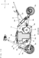
Fig. 1 is a side view which shows a vehicle according to a preferred embodiment. -
Fig. 2 is a plan view which shows the vehicle inFig. 1 . -
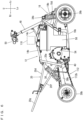
Fig. 3 is a perspective view which shows the vehicle with exterior components removed. -
Fig. 4 is a front view which shows the vehicle inFig. 3 . -
Fig. 5 is a side view which shows the vehicle inFig. 3 viewed from the left. -
Fig. 6 is a side view which shows the vehicle inFig. 3 viewed from the right. -
Fig. 7 is a plan view which shows the vehicle inFig. 3 . -
Fig. 8 is a bottom view which shows the vehicle inFig. 3 . -
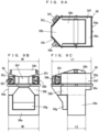
Figs. 9A to 9C show a battery, whereinFig. 9A is a plan view,Fig. 9B is a front view, andFig. 9C is a side view. -
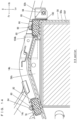
Fig. 10 is an illustrative sectional view taken along line A-A inFig. 7 . -
Fig. 11 is an illustrative sectional view taken along line B-B inFig. 5 . -
Fig. 12 is an illustrative sectional view taken along the line A-A which shows a vicinity of a battery lower portion. -
Fig. 13 is an enlarged perspective view which shows a vicinity of a battery upper portion. -
Fig. 14 is an illustrative sectional view taken along the line A-A which shows a vicinity of the battery upper portion. -
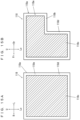
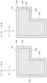
Figs. 15A and 15B show a variation of the battery, whereinFig. 15A is an illustrative front view, andFig. 15B is an illustrative side view. -
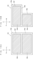
Figs. 16A and 16B show another variation of the battery, whereinFig. 16A is an illustrative front view, andFig. 16B is an illustrative side view. -
Figs. 17A and 17B show still another variation of the battery, whereinFig. 17A is an illustrative front view, andFig. 17B is an illustrative side view. -
Figs. 18A and 18B show still another variation of the battery, whereinFig. 18A is an illustrative front view, andFig. 18B is an illustrative side view. -
Figs. 19A and 19B show another variation of the battery, whereinFig. 19A is an illustrative front view, andFig. 19B is an illustrative side view. -
Figs. 20A and 20B show another variation of the battery, whereinFig. 20A is an illustrative front view, andFig. 20B is an illustrative side view. -
Figs. 21A and 21B show still another variation of the battery, whereinFig. 21A is an illustrative front view, andFig. 21B is an illustrative side view. -
Figs. 22A and 22B show still another variation of the battery, whereinFig. 22A is an illustrative front view, andFig. 22B is an illustrative side view. - Hereinafter, preferred embodiments will be described with reference to the drawings. It should be noted here that the terms front and rear, left and right, and up and down used in the preferred embodiments refer to front and rear, left and right, and up and down based on the state where a driver of the
vehicle 10 is seated in a straddled seat 114 (which will be described below), facing a bar handle 50 (which will be described below). In the drawings, "Fr" indicates forward, "Rr" indicates rearward, "R" indicates rightward, "L" indicates leftward, "U" indicates upward and "Lo" indicates downward. Accordingly, a fore-aft direction of the vehicle extends from rearward Rr to forward Fr and vice versa. A left-right direction of the vehicle extends from the rightward R to leftward L and vice versa. The left-right direction of the vehicle is synonymous to the widthwise direction of the vehicle. An upward-downward direction of the vehicle extends from upward U to downward and vice versa. The upward-downward direction of the vehicle is synonymous to the vertical direction of the vehicle. - Referring to
Fig. 1 andFig. 2 , avehicle 10 according to a preferred embodiment is an electric ATV which carries one person. - Referring to
Fig. 3 through Fig. 8 , thevehicle 10 includes abody frame 12. Thebody frame 12 includes a pair ofupper frames lower frames front frame 18, and arear frame 20. - The pair of
upper frames upper frames support frame 14c which supports a steering shaft 48 (which will be described below). Thesupport frame 14c is generally V-shaped, and is provided on the pair ofupper frames - The pair of
lower frames upper frames - The
front frame 18 connects front portions of the pair ofupper frames lower frames front frame 18 includes a pair offirst frames upper frames lower frames second frames upper frames lower frames second frames - The
rear frame 20 connects rear portions of the pair ofupper frames lower frames rear frame 20 includes athird frame 20a which is generally U-shaped in a rear view and generally V-shaped in a side view and connects the rear portions of the pair ofupper frames lower frames cross member 20b which connects two end portions of thethird frame 20a; a pair offourth frames third frame 20a; a pair offifth frames third frame 20a; and asixth frame 20g which is generally U-shaped. Thesixth frame 20g is located so that its first end portion is sandwiched by a rear end portion of thefourth frame 20c and a rear end portion of thefifth frame 20e while its second end portion is sandwiched by a rear end portion of thefourth frame 20d and a rear end portion of thefifth frame 20f. - A pair of
front wheels body frame 12 and a pair ofrear wheels -
Fig. 1 andFig. 2 ). Thefront wheels wheels tires wheels rear wheels wheels tires wheels - The pair of
front wheels body frame 12 viasuspensions - The pair of
rear wheels body frame 12 via asuspension 36,swing arms third frame 20a of therear frame 20 are connected with each other via apivot shaft 40 which extends in a widthwise direction of the vehicle. Therear wheels axle 42 which extends widthwise of the vehicle. At an intermediate portion of theaxle 42, anarm support portion 44 is attached rotatably with respect to theaxle 42. Thepivot shaft 40 and thearm support portion 44 are connected with each other by theswing arms swing arms portion 46. Thesuspension 36 is provided at an intermediate portion in the vehicle's widthwise direction, and connects thethird frame 20a with the connectingportion 46. - A steering
shaft 48 is provided to extend through a space between the pair ofupper frames shaft 48 has its lower end portion connected with the pair offirst frames front frame 18. The steeringshaft 48 is supported, at a position slightly above its intermediate portion, by thesupport frame 14c. A bar handle 50 to steer the pair offront wheels shaft 48. The bar handle 50 is provided at a higher position than the straddledseat 114. When the bar handle 50 is operated, the steeringshaft 48 is rotated to steer thefront wheels - A pair of
steps third frame 20a of therear frame 20 to extend outward of the vehicle. - The
body frame 12 supports adrive motor 54 which drives the pair ofrear wheels battery 56 which supplies electric power to thedrive motor 54. Thedrive motor 54 and thebattery 56 are located on the pair oflower frames drive motor 54 is behind thebattery 56. Preferably, thebattery 56 is an interchangeable rechargeable battery. - Referring to
Figs. 9A to 9C , thebattery 56 includes abattery case 56a. Thebattery case 56a includesprojections battery case 56a houses abattery module 56d (seeFig. 10 ). - The
battery 56 includes a batterylower portion 56e and a batteryupper portion 56f provided on and above the batterylower portion 56e. On a front surface of the batterylower portion 56e, at its generally intermediate region, a protrudingportion 56g is provided. On an upper surface of the batteryupper portion 56f, a protrudingportion 56h is provided. The batteryupper portion 56f includes theprojection 56b overhanging farther forward than the batterylower portion 56e, and theprojection 56c overhanging farther rearward than the batterylower portion 56e. As described, the batteryupper portion 56f overhangs forward and rearward with respect to the batterylower portion 56e. The batteryupper portion 56f and the batterylower portion 56e look like a letter T in a side view. Also, the batteryupper portion 56f has a shape that corresponds or follows a shape of the pair ofsecond frames Fig. 10 ). At least a portion of thedrive motor 54 is below theprojection 56c, preferably directly below theprojection 56c. In other words, at least a portion of thedrive motor 54 overlaps theprojection 56c in a plan view. - In a side view, the battery
upper portion 56f has a length L1 which is greater than a length L2 of the batterylower portion 56e. Also, in a horizontal direction, the batteryupper portion 56f has an area of cross section which is greater than an area of cross section of the batterylower portion 56e. The batteryupper portion 56f has a lateral width W1 which is equal or substantially equal to a lateral width W2 of the batterylower portion 56e. - The battery
upper portion 56f includes slantedportions projection 56b includes the slantedportions slanted portions connectors 56k, 56l, respectively. The charging/dischargingconnectors 56k, 56l are provided in the batteryupper portion 56f such that it does not protrude from a front end and a rear end of the batteryupper portion 56f. - Referring to
Fig. 5 ,Fig. 6 andFig. 10 , in a side view, thedrive motor 54 and thebattery 56 are located in a region which is surrounded by theupper frames lower frames second frames front frame 18, and thethird frame 20a of therear frame 20. In the present preferred embodiment, thedrive motor 54 and thebattery 56 are located inside the region which is surrounded by theupper frames lower frames second frames front frame 18, and thethird frame 20a of therear frame 20, and do not overlap these frames in a side view. Anoutput shaft 54a of thedrive motor 54 is able to be positioned rearward and downward in the region. In a side view, thedrive motor 54 and thebattery 56 do not protrude downward from the pair oflower frames - The
battery 56 is supported by theupper frames lower frames battery 56 is supported as described below. - Referring to
Fig. 5 ,Fig. 6 , andFig. 10 throughFig. 12 , the pair ofsecond frames front frame 18 are connected with each other by arectangular pipe 58 extending in the vehicle's width direction. Therectangular pipe 58 includes aflange portion 58a in its first end region (left end region), and aflange portion 58b in its second end region (right end region). Theflange portion 58b of therectangular pipe 58 includes abracket 60 attached thereto with twofasteners 62. Thebracket 60 and theflange portion 58a of therectangular pipe 58 hold the protrudingportion 56g which is provided on the front surface of the batterylower portion 56e from both sides. Between therectangular pipe 58 and the protrudingportion 56g, anelastic member 64 made of, for example, rubber is inserted. Between thebracket 60 and the protrudingportion 56g, anelastic member 66 made of, for example, rubber is inserted. - Referring to
Fig. 8 andFig. 12 , thelower frames bracket 68. On thebracket 68, there is provided arectangular pipe 70 which extends in the vehicle's width direction. Thebracket 68 supports a lower surface of the batterylower portion 56e. Therectangular pipe 70 supports a lower portion of a rear surface of the batterylower portion 56e. Between thebracket 68 and the lower surface of the batterylower portion 56e, anelastic member 72 made of, for example, rubber is inserted. Between therectangular pipe 70 and the lower portion of the rear surface of the batterylower portion 56e, anelastic member 74 made of, for example, rubber is inserted. - Referring to
Fig. 13 andFig. 14 ,platy flange portions upper frames support frame 14c is attached. Theflange portions bracket 78 that extends in the vehicle's width direction and has a generally U-shaped section. Thebracket 78 is fixed to theflange portions fasteners 80. Thebracket 78 has a lower surface to which anelastic member 82 made of, for example, rubber and extending in the vehicle's width direction is attached with twofasteners 84. Theelastic member 82 is inserted between thebracket 78 and a forward portion of the upper surface of the batteryupper portion 56f. -
Platy flange portions upper frames flange portions flange portions bracket 88 extending in the vehicle's width direction and having a generally J-shaped section. Thebracket 88 is fixed to theflange portions fasteners 90. Thebracket 88 includes a rear portion, to both sides of which there arebrackets fasteners 94 to support theupper frames bracket 88 has a lower surface, to which anelastic member 96 made of, for example, rubber and extending in the vehicle's width direction is attached with twofasteners 98. Theelastic member 96 is inserted between thebracket 88 and a rearward portion of the upper surface of the batteryupper portion 56f. Also, anelastic member 100 made of, for example, rubber is inserted between thebracket 88 and an upper portion of a rear surface of the batteryupper portion 56f. -
Brackets upper frames flange portions flange portions Platy brackets brackets bracket 104a is fixed to thebracket 102a with twofasteners 106. Thebracket 104b is fixed to thebracket 102b with twofasteners 106. Thebrackets portion 56h of the upper surface of the batteryupper portion 56f from the vehicle's width direction. Anelastic member 108 made of, for example, rubber is inserted between each of thebrackets portion 56h. - In this way, the
elastic members upper frames battery 56, and theelastic members lower frames battery 56. - Also, the
rectangular pipe 58 and thebracket 60 are in face-to-face contact with a front portion of thebattery 56 via theelastic members bracket 68 is in face-to-face contact with a lower surface of thebattery 56 via theelastic member 72; and therectangular pipe 70 in face-to-face contact with a lower portion of a rear surface of thebattery 56 via theelastic member 74. Also, thebracket 78 is in face-to-face contact with a front portion of the upper surface of thebattery 56 via theelastic members 82; thebracket 88 in face-to-face contact with a rear portion of the upper surface and an upper portion of the rear surface of thebattery 56 via theelastic members brackets battery 56 via the twoelastic members 108. In this arrangement, thebattery 56 is fixed from up-down, left-right, and fore-aft directions for easy attachment/detachment. - Referring to
Fig. 5 through Fig. 7 , a motor control unit (MCU) 110 is provided above thebattery 56 in order to control thedrive motor 54. Themotor control unit 110 is supported by the pair ofupper frames output shaft 54a of thedrive motor 54 is transmitted to the pair ofrear wheels power transmission member 112 to drive the pair ofrear wheels power transmission member 112 includes asprocket 112a attached to theoutput shaft 54a, a sprocket (not illustrated) attached to theaxle 42, and achain 112b connecting thesprocket 112a and the axle-side sprocket with each other. Therefore, the power from theoutput shaft 54a is transmitted through thesprocket 112a, thechain 112b, and the axle-side sprocket, to theaxle 42, and then to the pair ofrear wheels - Referring to
Fig. 1 andFig. 2 , the straddledseat 114 and anexterior portion 116 are mounted to thebody frame 12. - The straddled
seat 114 is at a position higher than thedrive motor 54, and is supported by the pair offourth frames rear frame 20. - The
exterior portion 116 includes atop cover 116a located ahead of the straddledseat 114, afront fender 116b located ahead of thetop cover 116a, and arear fender 116c located behind thetop cover 116a to surround the straddledseat 114. Thetop cover 116a includes aconsole box 116d attached thereto. Theconsole box 116d is above thebattery 56. - According to the
vehicle 10 as described thus far, the batteryupper portion 56f includes theprojections lower portion 56e, and at least a portion of thedrive motor 54 is below or directly below theprojection 56c. By ingeniously designing the shape of thebattery 56, it becomes possible to make effective use of the space below theprojections drive motor 54 closely to thebattery 56, i.e., to lay out thebattery 56 and thedrive motor 54 satisfactorily within a limited space while allowing for increased battery volume. - In a side view, the battery
upper portion 56f has the length L1, which is greater than the length L2 of the batterylower portion 56e. Therefore, it is possible to easily provide theprojections projections - In a horizontal direction, the battery
upper portion 56f has an area of cross section which is greater than an area of cross section of the batterylower portion 56e. Therefore, it is possible to easily provide theprojections projections - The
projection 56c overhangs rearward with respect to the batterylower portion 56e. Therefore, it is possible to position thedrive motor 54 behind thebattery 56. In other words, it is possible to position thebattery 56 in a vacant space ahead of thedrive motor 54, thus making effective use of the limited space. - The
battery 56 includes thebattery case 56a which includes theprojections battery 56 includes a battery case, it is possible to easily provide theprojections projections - The battery
upper portion 56f projects forward with respect to the batterylower portion 56e and corresponds to or follows the shape of the pair ofsecond frames front frame 18. Therefore, it is possible to position thebattery 56 satisfactorily in the space which is defined by the pair ofsecond frames front frame 18. - The battery
upper portion 56f overhangs forward and rearward with respect to the batterylower portion 56e. Therefore, even in a case where the region which is surrounded by theupper frames lower frames front frame 18, and therear frame 20 is narrower in its lower portion than its upper portion in a side view, it is possible to position thebattery 56 and thedrive motor 54 satisfactorily in the region. - The battery
upper portion 56f has a lateral width W1 which is equal or substantially equal to a lateral width W2 of the batterylower portion 56e. Therefore, it is possible to provide thebattery 56 with a larger volume even if the space is limited. - The charging/discharging
connectors 56k, 56l are provided in the batteryupper portion 56f so as not to protrude from a front end and a rear end of the batteryupper portion 56f. Therefore, when thebattery 56 is removed from thevehicle 10, it is possible to easily remove thebattery 56 without causing the charging/dischargingconnectors 56k, 56l to be caught by thefront frame 18 or therear frame 20. - The battery
upper portion 56f includes the slantedportions connectors connectors battery 56. - The
elastic members upper frames battery 56, and theelastic members lower frames battery 56. Therefore, it is possible for theelastic members battery 56 when the vehicle is running. - Preferred embodiments described above may be suitably applied to an ATV.
- The battery may be configured as described below.
- Referring to
Figs. 15A and 15B , abattery 118 includes abattery case 118a. Thebattery case 118a includes aprojection 118b overhanging rearward. Thebattery case 118a houses onebattery module 118c. - The
battery 118 includes a batterylower portion 118d and a batteryupper portion 118e provided on the batterylower portion 118d. The batteryupper portion 118e includes theprojection 118b overhanging more rearward than the batterylower portion 118d. As described, the batteryupper portion 118e overhangs rearward with respect to the batterylower portion 118d. The batteryupper portion 118e and the batterylower portion 118d have the shape of an inverted letter L in a side view. - In a side view, the battery
upper portion 118e has a length which is greater than a length of the batterylower portion 118d. Also, in a horizontal direction, the batteryupper portion 118e has an area of cross section which is greater than an area of cross section of the batterylower portion 118d. The batteryupper portion 118e has a lateral width which is equal or substantially equal to a lateral width of the batterylower portion 118d. - According to the
battery 118, it is possible to effectively use a layout space, and to have thebattery 118 follow or correspond to the shape of thebattery module 118c. - Referring to
Figs. 16A and 16B , abattery 120 includes abattery case 120a. Thebattery case 120a includes aprojection 120b overhanging rearward. Thebattery case 120a houses twobattery modules - The
battery 120 includes a batterylower portion 120e and a batteryupper portion 120f provided on the batterylower portion 120e. The batteryupper portion 120f includes theprojection 120b overhanging more rearward than the batterylower portion 120e. As described, the batteryupper portion 120f overhangs rearward with respect to the batterylower portion 120e. The batteryupper portion 120f and the batterylower portion 120e have the shape of an inverted letter L in a side view. - In a side view, the battery
upper portion 120f has a length which is greater than a length of the batterylower portion 120e. Also, in a horizontal direction, the batteryupper portion 120f has an area of cross section which is greater than an area of cross section of the batterylower portion 120e. The batteryupper portion 120f has a lateral width which is equal or substantially equal to a lateral width of the batterylower portion 120e. - According to the
battery 120, it is possible to effectively use a layout space, and to easily provide thebattery 120 with twobattery modules - Referring to
Figs. 17A and 17B , abattery 122 includes abattery case 122a. Thebattery case 122a includes aprojection 122b overhanging rearward. Thebattery case 122a houses threebattery modules - The
battery 122 includes a batterylower portion 122f and a batteryupper portion 122g provided on the batterylower portion 122f. The batteryupper portion 122g includes theprojection 122b overhanging more rearward than the batterylower portion 122f. As described, the batteryupper portion 122g overhangs rearward with respect to the batterylower portion 122f. The batteryupper portion 122g and the batterylower portion 122f have the shape of an inverted letter L in a side view. - In a side view, the battery
upper portion 122g has a length which is greater than a length of the batterylower portion 122f. Also, in a horizontal direction, the batteryupper portion 122g has an area of cross section which is greater than an area of cross section of the batterylower portion 122f. The batteryupper portion 122g has a lateral width which is equal or substantially equal to a lateral width of the batterylower portion 122f. - According to the
battery 122, it is possible to effectively use a layout space, and to easily provide thebattery 122 with threebattery modules - Referring to
Figs. 18A and 18B , abattery 124 includes abattery case 124a. Thebattery case 124a includes aprojection 124b overhanging laterally (leftward in the present preferred embodiment). Thebattery case 124a houses onebattery module 124c. - The
battery 124 includes a batterylower portion 124d and a batteryupper portion 124e provided on the batterylower portion 124d. The batteryupper portion 124e includes aprojection 124b overhanging more laterally than the batterylower portion 124d. As described, the batteryupper portion 124e overhangs laterally with respect to the batterylower portion 124d. The batteryupper portion 124e and the batterylower portion 124d have the shape of an inverted letter L in a front view. - In a side view, the battery
upper portion 124e has a length which is equal or substantially equal to a length of the batterylower portion 124d. Also, in a horizontal direction, the batteryupper portion 124e has an area of cross section which is greater than an area of cross section of the batterylower portion 124d. The batteryupper portion 124e has a lateral width which is greater than a lateral width of the batterylower portion 124d. - According to the
battery 124, it is possible to effectively use a layout space, and to easily provide thebattery 124 with a shape that follows the shape of thebattery module 124c. - Referring to
Figs. 19A and 19B , abattery 126 includes abattery case 126a. Thebattery case 126a includes aprojection 126b overhanging laterally (leftward in the present preferred embodiment) and rearward. Thebattery case 126a houses onebattery module 126c. - The
battery 126 includes a batterylower portion 126d and a batteryupper portion 126e provided on the batterylower portion 126d. The batteryupper portion 126e includes aprojection 126b overhanging more laterally and rearward than the batterylower portion 126d. As described, the batteryupper portion 126e overhangs laterally and rearward with respect to the batterylower portion 126d. The batteryupper portion 126e and the batterylower portion 126d have the shape of an inverted letter L in a front view and a side view. - In a side view, the battery
upper portion 126e has a length which is greater than a length of the batterylower portion 126d. Also, in a horizontal direction, the batteryupper portion 126e has an area of cross section which is greater than an area of cross section of the batterylower portion 126d. The batteryupper portion 126e has a lateral width which is greater than a lateral width of the batterylower portion 126d. - According to the
battery 126, it is possible to effectively use a layout space, and to form thebattery 126 to follow the shape of thebattery module 126c. - Referring to
Figs. 20A and 20B , abattery 128 includesbattery cases battery case 128b includes aprojection 128c overhanging rearward. Thebattery case 128a houses onebattery module 128d, while thebattery case 128b houses onebattery module 128e. - In this variation, a battery
lower portion 128f includes thebattery case 128a and thebattery module 128d, while a batteryupper portion 128g includes thebattery case 128b and thebattery module 128e. The batteryupper portion 128g includes theprojection 128c overhanging more rearward than the batterylower portion 128f. As described, the batteryupper portion 128g overhangs rearward with respect to the batterylower portion 128f. The batteryupper portion 128g and the batterylower portion 128f have the shape of an inverted letter L in a side view. - In a side view, the battery
upper portion 128g has a length which is greater than a length of the batterylower portion 128f. Also, in a horizontal direction, the batteryupper portion 128g has an area of cross section which is greater than an area of cross section of the batterylower portion 128f. The batteryupper portion 128g has a lateral width which is equal or substantially equal to a lateral width of the batterylower portion 128f. - According to the
battery 128, it is possible to effectively use a layout space, and by making the batteryupper portion 128g and the batterylower portion 128f as separate components from each other, it becomes possible to easily obtain thebattery 128 having a desirable shape by simply placing the batteryupper portion 128g on the batterylower portion 128f. - Referring to
Figs. 21A and 21B , abattery 130 includes abattery case 130a. Thebattery case 130a includes aprojection 130b overhanging rearward. Thebattery case 130a houses twobattery modules - The
battery 130 includes a batterylower portion 130e and a batteryupper portion 130f provided on the batterylower portion 130e. The batteryupper portion 130f is provided on the batterylower portion 130e at an intermediate region in a width direction. Therefore, in a front view, the batteryupper portion 130f and the batterylower portion 130e have a convex shape. The batteryupper portion 130f includes aprojection 130b overhanging more rearward than the batterylower portion 130e. As described, the batteryupper portion 130f overhangs rearward with respect to the batterylower portion 130e. The batteryupper portion 130f and the batterylower portion 130e have the shape of an inverted letter L in a side view. - In a side view, the battery
upper portion 130f has a length which is greater than a length of the batterylower portion 130e. The batteryupper portion 130f has a lateral width which is smaller than a lateral width of the batterylower portion 130e. - According to the
battery 130, it is possible to effectively use a layout space, and it becomes possible for the driver of the vehicle to straddle thebattery 130 easily. - Referring to
Figs. 22A and 22B , abattery 132 includes abattery case 132a. Thebattery case 132a includes aprojection 132b overhanging rearward. Thebattery case 132a houses threebattery modules - The
battery 132 includes a batterylower portion 132f and a batteryupper portion 132g provided on the batterylower portion 132f. The batteryupper portion 132g includes aprojection 132b overhanging more rearward than batterylower portion 132f. As described, the batteryupper portion 132g overhangs rearward with respect to the batterylower portion 132f. The batteryupper portion 132g and the batterylower portion 132f have the shape of an inverted letter of L in a side view. Also, the batteryupper portion 132g includes a protrudingportion 132h protruding upward. - In a side view, the battery
upper portion 132g has a length which is greater than a length of the batterylower portion 132f. Also, in a horizontal direction, the batteryupper portion 132g has an area of cross section which is greater than an area of cross section of the batterylower portion 132f. The batteryupper portion 132g has a lateral width which is equal or substantially equal to a lateral width of the batterylower portion 132f. - According to the
battery 132, it is possible to provide thebattery 132 within a given layout space by ingeniously designing the shapes of thebattery case 132a and thebattery modules - It should be noted here that the projection of the battery upper portion should project at least in a horizontal direction with respect to the battery lower portion.
- The battery may have the shape of an inverted triangle as a result of a combination of the battery upper portion and the battery lower portion.
- The elastic member should be provided between the battery and at least one of the upper frame and the lower frame.
Claims (13)
- A vehicle (10) comprising:at least one upper frame (14a, 14b);at least one lower frame (16a, 16b);a front frame (18) connecting a front portion of the upper frame (14a, 14b) with the lower frame (16a, 16b);a rear frame (20) connecting a rear portion of the upper frame (14a, 14b) with a rear portion of the lower frame (16a, 16b);a pair of rear wheels (24a, 24b);a drive motor (54) configured to drive the pair of rear wheels (24a, 24b); anda battery (56, 118, 120, 122, 124, 126, 128, 130, 132) supported by the upper frame (14a, 14b) and the lower frame (16a, 16b) and configured to supply electric power to the drive motor (54); whereinthe battery (56, 118, 120, 122, 124, 126, 128, 130, 132) includes a battery lower portion (56e, 118d, 120e, 122f, 124d, 126d, 128f, 130e, 132f) and a battery upper portion (56f, 118e, 120f, 122g, 124e, 126e, 128g, 130f, 132g) above the battery lower portion (56e, 118d, 120e, 122f, 124d, 126d, 128f, 130e, 132f) with regard to an upward-downward direction of the vehicle;the battery upper portion (56f, 118e, 120f, 122g, 124e, 126e, 128g, 130f, 132g) includes a projection (56b, 56c, 118b, 120b, 122b, 124b, 126b, 128c, 130b, 132b) that overhangs in at least a horizontal direction of the vehicle with respect to the battery lower portion (56e, 118d, 120e, 122f, 124d, 126d, 128f, 130e, 132f); andat least a portion of the drive motor (54) is below the projection (56b, 56c, 118b, 120b, 122b, 124b, 126b, 128c, 130b, 132b) with regard to an upward-downward direction of the vehicle.
- The vehicle (10) according to claim 1, wherein a length (L1) of the battery upper portion (56f, 118e, 120f, 122g, 124e, 126e, 128g, 130f, 132g) is greater than a length (L2) of the battery lower portion (56e, 118d, 120e, 122f, 124d, 126d, 128f, 130e, 132f) with regard to a fore-aft direction of the vehicle in a side view of the vehicle.
- The vehicle (10) according to claim 1 or 2, wherein an area of a cross section of the battery upper portion (56f, 118e, 120f, 122g, 124e, 126e, 128g, 130f, 132g) is greater than an area of a cross section of the battery lower portion (56e, 118d, 120e, 122f, 124d, 126d, 128f, 130e, 132f) in the horizontal direction.
- The vehicle (10) according to any one of the claims 1 to 3, wherein the projection (56c, 118b, 120b, 122b, 124b, 126b, 128c, 130b, 132b) overhangs rearward with respect to the battery lower portion (56e, 118d, 120e, 122f, 124d, 126d, 128f, 130e, 132f) with regard to the fore-aft direction of the vehicle.
- The vehicle (10) according to any one of the claims 1 to 4, wherein the battery (56, 118, 120, 122, 124, 126, 128, 130, 132) includes a battery case (56a, 118a, 120a, 122a, 124a, 126a, 128b, 130a, 132a) that includes the projection (56b, 56c, 118b, 120b, 122b, 124b, 126b, 128c, 130b, 132b).
- The vehicle (10) according to any one of the claims 1 to 5, wherein the battery upper portion (56f) projects forward with respect to the battery lower portion (56e) with regard to the fore-aft direction of the vehicle and corresponds to a shape of the front frame (18).
- The vehicle (10) according to any one of the claims 1 to 6, wherein the battery upper portion (56f) overhangs forward and rearward with respect to the battery lower portion (56e) with regard to the fore-aft direction of the vehicle.
- The vehicle (10) according to any one of the claims 1 to 7, wherein a lateral width (W1) of the battery upper portion (56f, 118e, 120f, 122g, 128g, 132g) is equal or substantially equal to a lateral width (W2) of the battery lower portion (56e, 118d, 120e, 122f, 128f, 132f) with regard to a widthwise direction of the vehicle.
- The vehicle (10) according to any one of the claims 1 to 7, further comprising a charging/discharging connector (56k, 56l) in the battery upper portion (56f) that does protrude from a front end or a rear end of the battery upper portion (56f) with regard to the fore-aft direction of the vehicle.
- The vehicle (10) according to claim 9, wherein the battery upper portion (56f) further includes a slanted portion (56i, 56j) including the charging/discharging connector (56k, 56l).
- The vehicle (10) according to any one of the claims 1 to 10, further comprising an elastic member (82, 96, 100, 108; 64, 66, 72, 74) between the battery (56, 118, 120, 122, 124, 126, 128, 130, 132) and at least one of the upper frame (14a, 14b) and the lower frame (16a, 16b).
- The vehicle (10) according to any one of the claims 1 to 11, further comprising:a straddled seat (114) at a higher position than the drive motor (54) with regard to the upward-downward direction of the vehicle; anda bar handle (50) is at a higher position than the straddled seat (114) with regard to the upward-downward direction of the vehicle.
- The vehicle (10) according to any one of the claims 1 to 11, comprising:
a body frame (12) with a pair of the upper frames (14a, 14b) and a pair of the lower frames (16a, 16b), the front frame (18) connects the front portions of the pair of upper frames (14a, 14b) to the pair of lower frames (16a, 16b), and the rear frame (20) connects the rear portions of the pair of upper frames (14a, 14b) to the rear portions of the pair of lower frames (16a, 16b).
Applications Claiming Priority (1)
| Application Number | Priority Date | Filing Date | Title |
|---|---|---|---|
| JP2021207429A JP2023092281A (en) | 2021-12-21 | 2021-12-21 | vehicle |
Publications (2)
| Publication Number | Publication Date |
|---|---|
| EP4201721A1 true EP4201721A1 (en) | 2023-06-28 |
| EP4201721B1 EP4201721B1 (en) | 2024-08-07 |
Family
ID=84535889
Family Applications (1)
| Application Number | Title | Priority Date | Filing Date |
|---|---|---|---|
| EP22213428.0A Active EP4201721B1 (en) | 2021-12-21 | 2022-12-14 | Vehicle |
Country Status (3)
| Country | Link |
|---|---|
| US (1) | US12377929B2 (en) |
| EP (1) | EP4201721B1 (en) |
| JP (1) | JP2023092281A (en) |
Families Citing this family (3)
| Publication number | Priority date | Publication date | Assignee | Title |
|---|---|---|---|---|
| CN218703666U (en) * | 2022-01-25 | 2023-03-24 | 浙江春风动力股份有限公司 | Electric all-terrain vehicle |
| JP7756741B2 (en) * | 2024-03-15 | 2025-10-20 | 本田技研工業株式会社 | Vehicle structure |
| US20250296653A1 (en) * | 2024-03-22 | 2025-09-25 | Honda Motor Co., Ltd. | Mounting bracket for electric motor |
Citations (4)
| Publication number | Priority date | Publication date | Assignee | Title |
|---|---|---|---|---|
| JP4214759B2 (en) | 2002-10-29 | 2009-01-28 | スズキ株式会社 | Electric rough terrain vehicle |
| US20120103716A1 (en) * | 2010-10-29 | 2012-05-03 | Honda Motor Co., Ltd. | Drive assembly for an electric motorcycle, and electric motorcycle incorporating same |
| JP5509811B2 (en) | 2009-11-25 | 2014-06-04 | スズキ株式会社 | Electric rough terrain vehicle |
| US20150314830A1 (en) * | 2012-12-25 | 2015-11-05 | Kawasaki Jukogyo Kabushiki Kaisha | Electric vehicle |
Family Cites Families (12)
| Publication number | Priority date | Publication date | Assignee | Title |
|---|---|---|---|---|
| EP1836064A4 (en) * | 2004-12-30 | 2010-10-06 | American Off Road Technologies | IMPROVED REDUCED SIZE VEHICLE |
| CN103946108B (en) * | 2011-12-28 | 2016-08-24 | 川崎重工业株式会社 | Saddle-type electric vehicle |
| JP5797775B2 (en) * | 2011-12-28 | 2015-10-21 | 川崎重工業株式会社 | Straddle-type electric vehicle |
| US9238497B2 (en) * | 2011-12-28 | 2016-01-19 | Kawasaki Jukogyo Kabushiki Kaisha | Electric motorcycle |
| US9840306B2 (en) * | 2012-10-03 | 2017-12-12 | Kawasaki Jukogyo Kabushiki Kaisha | Electric vehicle, and battery pack |
| US10011324B2 (en) * | 2012-12-25 | 2018-07-03 | Kawasaki Jukogyo Kabushiki Kaisha | Electric vehicle |
| US9868490B2 (en) * | 2012-12-25 | 2018-01-16 | Kawasaki Jukogyo Kabushiki Kaisha | Electric vehicle |
| JP6001681B2 (en) * | 2012-12-25 | 2016-10-05 | 川崎重工業株式会社 | Electric vehicle |
| CN104884344B (en) * | 2012-12-25 | 2017-07-07 | 川崎重工业株式会社 | straddle vehicle |
| CN105705408A (en) * | 2013-11-06 | 2016-06-22 | 雅马哈发动机株式会社 | Riding Electric Vehicle |
| US10710635B2 (en) * | 2017-12-18 | 2020-07-14 | Honda Motor Co., Ltd. | Autonomous all-terrain vehicle frame structure |
| WO2023044439A1 (en) * | 2021-09-17 | 2023-03-23 | Polaris Industries Inc. | Electric all-terrain vehicle |
-
2021
- 2021-12-21 JP JP2021207429A patent/JP2023092281A/en active Pending
-
2022
- 2022-12-14 EP EP22213428.0A patent/EP4201721B1/en active Active
- 2022-12-15 US US18/081,748 patent/US12377929B2/en active Active
Patent Citations (4)
| Publication number | Priority date | Publication date | Assignee | Title |
|---|---|---|---|---|
| JP4214759B2 (en) | 2002-10-29 | 2009-01-28 | スズキ株式会社 | Electric rough terrain vehicle |
| JP5509811B2 (en) | 2009-11-25 | 2014-06-04 | スズキ株式会社 | Electric rough terrain vehicle |
| US20120103716A1 (en) * | 2010-10-29 | 2012-05-03 | Honda Motor Co., Ltd. | Drive assembly for an electric motorcycle, and electric motorcycle incorporating same |
| US20150314830A1 (en) * | 2012-12-25 | 2015-11-05 | Kawasaki Jukogyo Kabushiki Kaisha | Electric vehicle |
Also Published As
| Publication number | Publication date |
|---|---|
| US12377929B2 (en) | 2025-08-05 |
| US20230192216A1 (en) | 2023-06-22 |
| EP4201721B1 (en) | 2024-08-07 |
| JP2023092281A (en) | 2023-07-03 |
Similar Documents
| Publication | Publication Date | Title |
|---|---|---|
| EP4201721B1 (en) | Vehicle | |
| US8047557B2 (en) | Vehicle body frame structure | |
| CA3123823C (en) | Electric snowmobile | |
| KR102785686B1 (en) | High voltage battery unit of vehicle and underbody of vehicle | |
| CA3101727A1 (en) | Side by side all terrain vehicle | |
| CN111114676B (en) | straddle-type electric vehicle | |
| US8641065B2 (en) | Battery-powered towing tractor | |
| KR102916833B1 (en) | Battery unit for vehicle and underbody of vehicle including the same | |
| CN112770964B (en) | Saddle-ride type electric vehicle | |
| EP4005842B1 (en) | Lower structure of vehicle | |
| US12594844B2 (en) | Electric work vehicle | |
| EP4046840B1 (en) | Electric vehicle | |
| US20230192232A1 (en) | Vehicle | |
| EP4206013B1 (en) | Vehicle | |
| JP7596747B2 (en) | Vehicle undercarriage | |
| CN120051413A (en) | Electric working vehicle | |
| WO2024142481A1 (en) | Electric work vehicle | |
| JP7552299B2 (en) | Vehicle undercarriage | |
| US20230192215A1 (en) | Vehicle | |
| JP4314663B2 (en) | Vehicle fuel tank structure | |
| CN223821786U (en) | All-terrain vehicle | |
| JP7103317B2 (en) | Work vehicle | |
| KR102898360B1 (en) | Battery unit for vehicle and underbody of vehicle including the same | |
| US20240157775A1 (en) | Work Vehicle | |
| JPS62214076A (en) | Battery housing structure of saddling type four-wheel car |
Legal Events
| Date | Code | Title | Description |
|---|---|---|---|
| PUAI | Public reference made under article 153(3) epc to a published international application that has entered the european phase |
Free format text: ORIGINAL CODE: 0009012 |
|
| STAA | Information on the status of an ep patent application or granted ep patent |
Free format text: STATUS: REQUEST FOR EXAMINATION WAS MADE |
|
| 17P | Request for examination filed |
Effective date: 20221214 |
|
| AK | Designated contracting states |
Kind code of ref document: A1 Designated state(s): AL AT BE BG CH CY CZ DE DK EE ES FI FR GB GR HR HU IE IS IT LI LT LU LV MC ME MK MT NL NO PL PT RO RS SE SI SK SM TR |
|
| P01 | Opt-out of the competence of the unified patent court (upc) registered |
Effective date: 20230713 |
|
| RBV | Designated contracting states (corrected) |
Designated state(s): AL AT BE BG CH CY CZ DE DK EE ES FI FR GB GR HR HU IE IS IT LI LT LU LV MC ME MK MT NL NO PL PT RO RS SE SI SK SM TR |
|
| RIC1 | Information provided on ipc code assigned before grant |
Ipc: B62J 43/20 20200101ALN20240313BHEP Ipc: H01M 50/249 20210101ALN20240313BHEP Ipc: B62K 5/01 20130101ALN20240313BHEP Ipc: B62J 43/16 20200101ALN20240313BHEP Ipc: B60L 50/64 20190101ALN20240313BHEP Ipc: H01M 50/207 20210101ALN20240313BHEP Ipc: H01M 50/102 20210101ALN20240313BHEP Ipc: B60K 1/00 20060101ALI20240313BHEP Ipc: B60K 1/04 20190101AFI20240313BHEP |
|
| GRAP | Despatch of communication of intention to grant a patent |
Free format text: ORIGINAL CODE: EPIDOSNIGR1 |
|
| STAA | Information on the status of an ep patent application or granted ep patent |
Free format text: STATUS: GRANT OF PATENT IS INTENDED |
|
| INTG | Intention to grant announced |
Effective date: 20240422 |
|
| GRAS | Grant fee paid |
Free format text: ORIGINAL CODE: EPIDOSNIGR3 |
|
| GRAA | (expected) grant |
Free format text: ORIGINAL CODE: 0009210 |
|
| STAA | Information on the status of an ep patent application or granted ep patent |
Free format text: STATUS: THE PATENT HAS BEEN GRANTED |
|
| AK | Designated contracting states |
Kind code of ref document: B1 Designated state(s): AL AT BE BG CH CY CZ DE DK EE ES FI FR GB GR HR HU IE IS IT LI LT LU LV MC ME MK MT NL NO PL PT RO RS SE SI SK SM TR |
|
| REG | Reference to a national code |
Ref country code: GB Ref legal event code: FG4D |
|
| REG | Reference to a national code |
Ref country code: CH Ref legal event code: EP |
|
| REG | Reference to a national code |
Ref country code: DE Ref legal event code: R096 Ref document number: 602022005168 Country of ref document: DE |
|
| REG | Reference to a national code |
Ref country code: IE Ref legal event code: FG4D |
|
| REG | Reference to a national code |
Ref country code: LT Ref legal event code: MG9D |
|
| REG | Reference to a national code |
Ref country code: NL Ref legal event code: MP Effective date: 20240807 |
|
| PG25 | Lapsed in a contracting state [announced via postgrant information from national office to epo] |
Ref country code: NO Free format text: LAPSE BECAUSE OF FAILURE TO SUBMIT A TRANSLATION OF THE DESCRIPTION OR TO PAY THE FEE WITHIN THE PRESCRIBED TIME-LIMIT Effective date: 20241107 |
|
| REG | Reference to a national code |
Ref country code: AT Ref legal event code: MK05 Ref document number: 1710564 Country of ref document: AT Kind code of ref document: T Effective date: 20240807 |
|
| PG25 | Lapsed in a contracting state [announced via postgrant information from national office to epo] |
Ref country code: GR Free format text: LAPSE BECAUSE OF FAILURE TO SUBMIT A TRANSLATION OF THE DESCRIPTION OR TO PAY THE FEE WITHIN THE PRESCRIBED TIME-LIMIT Effective date: 20241108 Ref country code: FI Free format text: LAPSE BECAUSE OF FAILURE TO SUBMIT A TRANSLATION OF THE DESCRIPTION OR TO PAY THE FEE WITHIN THE PRESCRIBED TIME-LIMIT Effective date: 20240807 Ref country code: NL Free format text: LAPSE BECAUSE OF FAILURE TO SUBMIT A TRANSLATION OF THE DESCRIPTION OR TO PAY THE FEE WITHIN THE PRESCRIBED TIME-LIMIT Effective date: 20240807 Ref country code: PL Free format text: LAPSE BECAUSE OF FAILURE TO SUBMIT A TRANSLATION OF THE DESCRIPTION OR TO PAY THE FEE WITHIN THE PRESCRIBED TIME-LIMIT Effective date: 20240807 Ref country code: PT Free format text: LAPSE BECAUSE OF FAILURE TO SUBMIT A TRANSLATION OF THE DESCRIPTION OR TO PAY THE FEE WITHIN THE PRESCRIBED TIME-LIMIT Effective date: 20241209 |
|
| PG25 | Lapsed in a contracting state [announced via postgrant information from national office to epo] |
Ref country code: BG Free format text: LAPSE BECAUSE OF FAILURE TO SUBMIT A TRANSLATION OF THE DESCRIPTION OR TO PAY THE FEE WITHIN THE PRESCRIBED TIME-LIMIT Effective date: 20240807 |
|
| PG25 | Lapsed in a contracting state [announced via postgrant information from national office to epo] |
Ref country code: LV Free format text: LAPSE BECAUSE OF FAILURE TO SUBMIT A TRANSLATION OF THE DESCRIPTION OR TO PAY THE FEE WITHIN THE PRESCRIBED TIME-LIMIT Effective date: 20240807 |
|
| PG25 | Lapsed in a contracting state [announced via postgrant information from national office to epo] |
Ref country code: AT Free format text: LAPSE BECAUSE OF FAILURE TO SUBMIT A TRANSLATION OF THE DESCRIPTION OR TO PAY THE FEE WITHIN THE PRESCRIBED TIME-LIMIT Effective date: 20240807 Ref country code: IS Free format text: LAPSE BECAUSE OF FAILURE TO SUBMIT A TRANSLATION OF THE DESCRIPTION OR TO PAY THE FEE WITHIN THE PRESCRIBED TIME-LIMIT Effective date: 20241207 |
|
| PG25 | Lapsed in a contracting state [announced via postgrant information from national office to epo] |
Ref country code: HR Free format text: LAPSE BECAUSE OF FAILURE TO SUBMIT A TRANSLATION OF THE DESCRIPTION OR TO PAY THE FEE WITHIN THE PRESCRIBED TIME-LIMIT Effective date: 20240807 |
|
| PG25 | Lapsed in a contracting state [announced via postgrant information from national office to epo] |
Ref country code: RS Free format text: LAPSE BECAUSE OF FAILURE TO SUBMIT A TRANSLATION OF THE DESCRIPTION OR TO PAY THE FEE WITHIN THE PRESCRIBED TIME-LIMIT Effective date: 20241107 Ref country code: ES Free format text: LAPSE BECAUSE OF FAILURE TO SUBMIT A TRANSLATION OF THE DESCRIPTION OR TO PAY THE FEE WITHIN THE PRESCRIBED TIME-LIMIT Effective date: 20240807 |
|
| PG25 | Lapsed in a contracting state [announced via postgrant information from national office to epo] |
Ref country code: RS Free format text: LAPSE BECAUSE OF FAILURE TO SUBMIT A TRANSLATION OF THE DESCRIPTION OR TO PAY THE FEE WITHIN THE PRESCRIBED TIME-LIMIT Effective date: 20241107 Ref country code: PT Free format text: LAPSE BECAUSE OF FAILURE TO SUBMIT A TRANSLATION OF THE DESCRIPTION OR TO PAY THE FEE WITHIN THE PRESCRIBED TIME-LIMIT Effective date: 20241209 Ref country code: PL Free format text: LAPSE BECAUSE OF FAILURE TO SUBMIT A TRANSLATION OF THE DESCRIPTION OR TO PAY THE FEE WITHIN THE PRESCRIBED TIME-LIMIT Effective date: 20240807 Ref country code: NO Free format text: LAPSE BECAUSE OF FAILURE TO SUBMIT A TRANSLATION OF THE DESCRIPTION OR TO PAY THE FEE WITHIN THE PRESCRIBED TIME-LIMIT Effective date: 20241107 Ref country code: NL Free format text: LAPSE BECAUSE OF FAILURE TO SUBMIT A TRANSLATION OF THE DESCRIPTION OR TO PAY THE FEE WITHIN THE PRESCRIBED TIME-LIMIT Effective date: 20240807 Ref country code: LV Free format text: LAPSE BECAUSE OF FAILURE TO SUBMIT A TRANSLATION OF THE DESCRIPTION OR TO PAY THE FEE WITHIN THE PRESCRIBED TIME-LIMIT Effective date: 20240807 Ref country code: IS Free format text: LAPSE BECAUSE OF FAILURE TO SUBMIT A TRANSLATION OF THE DESCRIPTION OR TO PAY THE FEE WITHIN THE PRESCRIBED TIME-LIMIT Effective date: 20241207 Ref country code: HR Free format text: LAPSE BECAUSE OF FAILURE TO SUBMIT A TRANSLATION OF THE DESCRIPTION OR TO PAY THE FEE WITHIN THE PRESCRIBED TIME-LIMIT Effective date: 20240807 Ref country code: GR Free format text: LAPSE BECAUSE OF FAILURE TO SUBMIT A TRANSLATION OF THE DESCRIPTION OR TO PAY THE FEE WITHIN THE PRESCRIBED TIME-LIMIT Effective date: 20241108 Ref country code: FI Free format text: LAPSE BECAUSE OF FAILURE TO SUBMIT A TRANSLATION OF THE DESCRIPTION OR TO PAY THE FEE WITHIN THE PRESCRIBED TIME-LIMIT Effective date: 20240807 Ref country code: ES Free format text: LAPSE BECAUSE OF FAILURE TO SUBMIT A TRANSLATION OF THE DESCRIPTION OR TO PAY THE FEE WITHIN THE PRESCRIBED TIME-LIMIT Effective date: 20240807 Ref country code: BG Free format text: LAPSE BECAUSE OF FAILURE TO SUBMIT A TRANSLATION OF THE DESCRIPTION OR TO PAY THE FEE WITHIN THE PRESCRIBED TIME-LIMIT Effective date: 20240807 Ref country code: AT Free format text: LAPSE BECAUSE OF FAILURE TO SUBMIT A TRANSLATION OF THE DESCRIPTION OR TO PAY THE FEE WITHIN THE PRESCRIBED TIME-LIMIT Effective date: 20240807 |
|
| PG25 | Lapsed in a contracting state [announced via postgrant information from national office to epo] |
Ref country code: DK Free format text: LAPSE BECAUSE OF FAILURE TO SUBMIT A TRANSLATION OF THE DESCRIPTION OR TO PAY THE FEE WITHIN THE PRESCRIBED TIME-LIMIT Effective date: 20240807 Ref country code: SM Free format text: LAPSE BECAUSE OF FAILURE TO SUBMIT A TRANSLATION OF THE DESCRIPTION OR TO PAY THE FEE WITHIN THE PRESCRIBED TIME-LIMIT Effective date: 20240807 |
|
| PG25 | Lapsed in a contracting state [announced via postgrant information from national office to epo] |
Ref country code: EE Free format text: LAPSE BECAUSE OF FAILURE TO SUBMIT A TRANSLATION OF THE DESCRIPTION OR TO PAY THE FEE WITHIN THE PRESCRIBED TIME-LIMIT Effective date: 20240807 |
|
| PG25 | Lapsed in a contracting state [announced via postgrant information from national office to epo] |
Ref country code: CZ Free format text: LAPSE BECAUSE OF FAILURE TO SUBMIT A TRANSLATION OF THE DESCRIPTION OR TO PAY THE FEE WITHIN THE PRESCRIBED TIME-LIMIT Effective date: 20240807 |
|
| PG25 | Lapsed in a contracting state [announced via postgrant information from national office to epo] |
Ref country code: SK Free format text: LAPSE BECAUSE OF FAILURE TO SUBMIT A TRANSLATION OF THE DESCRIPTION OR TO PAY THE FEE WITHIN THE PRESCRIBED TIME-LIMIT Effective date: 20240807 |
|
| REG | Reference to a national code |
Ref country code: DE Ref legal event code: R097 Ref document number: 602022005168 Country of ref document: DE |
|
| PLBE | No opposition filed within time limit |
Free format text: ORIGINAL CODE: 0009261 |
|
| STAA | Information on the status of an ep patent application or granted ep patent |
Free format text: STATUS: NO OPPOSITION FILED WITHIN TIME LIMIT |
|
| PG25 | Lapsed in a contracting state [announced via postgrant information from national office to epo] |
Ref country code: MC Free format text: LAPSE BECAUSE OF FAILURE TO SUBMIT A TRANSLATION OF THE DESCRIPTION OR TO PAY THE FEE WITHIN THE PRESCRIBED TIME-LIMIT Effective date: 20240807 |
|
| 26N | No opposition filed |
Effective date: 20250508 |
|
| PG25 | Lapsed in a contracting state [announced via postgrant information from national office to epo] |
Ref country code: LU Free format text: LAPSE BECAUSE OF NON-PAYMENT OF DUE FEES Effective date: 20241214 |
|
| PG25 | Lapsed in a contracting state [announced via postgrant information from national office to epo] |
Ref country code: SE Free format text: LAPSE BECAUSE OF FAILURE TO SUBMIT A TRANSLATION OF THE DESCRIPTION OR TO PAY THE FEE WITHIN THE PRESCRIBED TIME-LIMIT Effective date: 20240807 |
|
| REG | Reference to a national code |
Ref country code: BE Ref legal event code: MM Effective date: 20241231 |
|
| PG25 | Lapsed in a contracting state [announced via postgrant information from national office to epo] |
Ref country code: BE Free format text: LAPSE BECAUSE OF NON-PAYMENT OF DUE FEES Effective date: 20241231 |
|
| PG25 | Lapsed in a contracting state [announced via postgrant information from national office to epo] |
Ref country code: IE Free format text: LAPSE BECAUSE OF NON-PAYMENT OF DUE FEES Effective date: 20241214 |
|
| PG25 | Lapsed in a contracting state [announced via postgrant information from national office to epo] |
Ref country code: RO Free format text: LAPSE BECAUSE OF FAILURE TO SUBMIT A TRANSLATION OF THE DESCRIPTION OR TO PAY THE FEE WITHIN THE PRESCRIBED TIME-LIMIT Effective date: 20240807 |
|
| PGFP | Annual fee paid to national office [announced via postgrant information from national office to epo] |
Ref country code: DE Payment date: 20251211 Year of fee payment: 4 |
|
| PG25 | Lapsed in a contracting state [announced via postgrant information from national office to epo] |
Ref country code: IT Free format text: LAPSE BECAUSE OF NON-PAYMENT OF DUE FEES Effective date: 20241214 |
|
| PGFP | Annual fee paid to national office [announced via postgrant information from national office to epo] |
Ref country code: FR Payment date: 20251229 Year of fee payment: 4 |
|
| PG25 | Lapsed in a contracting state [announced via postgrant information from national office to epo] |
Ref country code: IT Free format text: LAPSE BECAUSE OF NON-PAYMENT OF DUE FEES Effective date: 20241214 |
|
| PGFP | Annual fee paid to national office [announced via postgrant information from national office to epo] |
Ref country code: IT Payment date: 20251231 Year of fee payment: 4 |
|
| PGRI | Patent reinstated in contracting state [announced from national office to epo] |
Ref country code: IT Effective date: 20241231 |