EP4201717A1 - Height sensor and vehicle comprising same - Google Patents
Height sensor and vehicle comprising same Download PDFInfo
- Publication number
- EP4201717A1 EP4201717A1 EP22211281.5A EP22211281A EP4201717A1 EP 4201717 A1 EP4201717 A1 EP 4201717A1 EP 22211281 A EP22211281 A EP 22211281A EP 4201717 A1 EP4201717 A1 EP 4201717A1
- Authority
- EP
- European Patent Office
- Prior art keywords
- arm
- height sensor
- auxiliary arm
- auxiliary
- swing arm
- Prior art date
- Legal status (The legal status is an assumption and is not a legal conclusion. Google has not performed a legal analysis and makes no representation as to the accuracy of the status listed.)
- Pending
Links
Images


Classifications
-
- B—PERFORMING OPERATIONS; TRANSPORTING
- B60—VEHICLES IN GENERAL
- B60G—VEHICLE SUSPENSION ARRANGEMENTS
- B60G17/00—Resilient suspensions having means for adjusting the spring or vibration-damper characteristics, for regulating the distance between a supporting surface and a sprung part of vehicle or for locking suspension during use to meet varying vehicular or surface conditions, e.g. due to speed or load
- B60G17/015—Resilient suspensions having means for adjusting the spring or vibration-damper characteristics, for regulating the distance between a supporting surface and a sprung part of vehicle or for locking suspension during use to meet varying vehicular or surface conditions, e.g. due to speed or load the regulating means comprising electric or electronic elements
- B60G17/019—Resilient suspensions having means for adjusting the spring or vibration-damper characteristics, for regulating the distance between a supporting surface and a sprung part of vehicle or for locking suspension during use to meet varying vehicular or surface conditions, e.g. due to speed or load the regulating means comprising electric or electronic elements characterised by the type of sensor or the arrangement thereof
-
- B—PERFORMING OPERATIONS; TRANSPORTING
- B60—VEHICLES IN GENERAL
- B60G—VEHICLE SUSPENSION ARRANGEMENTS
- B60G7/00—Pivoted suspension arms; Accessories thereof
- B60G7/001—Suspension arms, e.g. constructional features
- B60G7/003—Suspension arms, e.g. constructional features of adjustable length
-
- B—PERFORMING OPERATIONS; TRANSPORTING
- B60—VEHICLES IN GENERAL
- B60G—VEHICLE SUSPENSION ARRANGEMENTS
- B60G2204/00—Indexing codes related to suspensions per se or to auxiliary parts
- B60G2204/10—Mounting of suspension elements
- B60G2204/11—Mounting of sensors thereon
- B60G2204/116—Sensors coupled to the suspension arm
- B60G2204/1162—Sensors coupled to the suspension arm directly mounted on the suspension arm
-
- B—PERFORMING OPERATIONS; TRANSPORTING
- B60—VEHICLES IN GENERAL
- B60G—VEHICLE SUSPENSION ARRANGEMENTS
- B60G2400/00—Indexing codes relating to detected, measured or calculated conditions or factors
- B60G2400/25—Stroke; Height; Displacement
-
- B—PERFORMING OPERATIONS; TRANSPORTING
- B60—VEHICLES IN GENERAL
- B60G—VEHICLE SUSPENSION ARRANGEMENTS
- B60G2500/00—Indexing codes relating to the regulated action or device
- B60G2500/30—Height or ground clearance
Definitions
- the present utility model relates to the technical field of sensors, in particular to a height sensor for a motor vehicle and a vehicle comprising the height sensor.
- Height sensors are an important component of motor vehicle lamp or chassis control systems.
- the height of the vehicle's low beam lamps needs to be controlled promptly according to vehicle body height and the road surface conditions, to prevent the vehicle lamps from causing dazzle, which would compromise drivers' driving safety.
- a height sensor needs to be used to detect changes in the vehicle body height (chassis height) in real time.
- the height sensor is usually mounted at the motor vehicle chassis suspension; when the vehicle body height changes, a swing arm of the height sensor is driven to rotate by a connecting rod that moves in linkage with the suspension, thereby changing the strength of a magnetic field, and a height change signal is outputted after processing by the height sensor.
- the effective length of the swing arm is generally fixed, so it is not possible to match the sensor to different chassis suspension structures by changing the swing arm length. Swing arms of different lengths need to be developed for different chassis suspension structures, resulting in a large number of swing arm molds, high development costs and poor versatility.
- the present utility model provides a height sensor and a vehicle comprising the height sensor.
- the height sensor is suitable for, and can be matched to, different chassis suspension structures, so is highly versatile with a low development cost.
- the present utility model provides a height sensor, comprising a sensor body, a swing arm and a connecting rod, a first end of the swing arm being movably connected to the sensor body, and a second end of the swing arm being movably connected to the connecting rod; the swing arm is configured as a structure with an adjustable working length.
- the swing arm further comprises a main arm and an auxiliary arm, one end of the main arm being connected to the auxiliary arm, another end of the main arm being movably connected to the sensor body, and the auxiliary arm also being movably connected to the connecting rod; and the working length of the swing arm is adjusted by adjusting a cooperative connection relationship between the main arm and the auxiliary arm.
- the cooperative connection relationship between the main arm and the auxiliary arm is a relative assembly angle and/or assembly position between the main arm and the auxiliary arm.
- a connecting end of the main arm that is connected to the auxiliary arm is provided with a mounting hole, and multiple limiting slots are provided around the mounting hole.
- the multiple limiting slots are arranged to surround the mounting hole.
- a fixing shaft and a limiting protrusion are provided on the auxiliary arm; the fixing shaft is connected to the mounting hole in the main arm in a cooperative manner, and the limiting protrusion is connected to the limiting slot on the main arm by engagement; and the working length of the swing arm is adjusted by adjusting an angle of rotation of the auxiliary arm relative to the main arm about the fixing shaft.
- a ball head or a ball socket is further provided on the auxiliary arm, the ball head or ball socket being movably connected to a ball socket or ball head correspondingly provided on the connecting rod.
- the positions of the limiting protrusion and the ball head or ball socket on the auxiliary arm are at two sides of the fixing shaft respectively, and the protrusion direction of the ball head or ball socket on the auxiliary arm is opposite to the protrusion direction of the limiting protrusion and the fixing shaft on the auxiliary arm.
- the fixing shaft passes through the mounting hole, and is connected to a fastener to fixedly connect the main arm to the auxiliary arm.
- the present utility model further provides a vehicle, comprising the height sensor as described above.
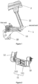
- Fig. 1 is a schematic drawing of an operating state of a height sensor in a preferred embodiment of the present utility model
- Fig. 2 is a schematic drawing of part of the structure at the back of the height sensor in Fig. 1 .
- the present utility model provides a height sensor 1, mounted between a vehicle chassis (not shown) and a chassis suspension 2 for example, and used to measure changes in motor vehicle chassis height.
- the height sensor 1 comprises a sensor body 10, a swing arm 11 and a connecting rod 12.
- a first end of the swing arm 11 is rotatably connected to the sensor body 10, such that the swing arm 11 can swing to and fro relative to the sensor body 10.
- a second end of the swing arm 11 is movably connected to the connecting rod 12.
- the second end of the swing arm 11 is connected to the connecting rod 12 via a ball joint formed by a movable ball head and ball socket.
- the chassis suspension 2 drives the connecting rod 12 to move; the movement of the connecting rod 12 drives the swing arm 11 to swing relative to the sensor body 10; a detection element in the sensor body 10 can measure chassis height change data according to the swing angle and direction of the swing arm 11, and this data is provided to a vehicle control unit in order to implement further control of the vehicle.
- Fig. 3 is a schematic drawing of the swing arm of the height sensor in a preferred embodiment of the present utility model
- Fig. 4a is a structural schematic drawing of the end of the main arm in Fig. 3 that is connected to the auxiliary arm
- Fig. 4b is a structural schematic drawing of the auxiliary arm in Fig. 3 .
- the swing arm 11 comprises a main arm 111 and an auxiliary arm 112.
- One end of the main arm 111 is fixedly connected to the auxiliary arm 112; the other end of the main arm 111 (i.e. the first end of the swing arm 11) is rotatably connected to the sensor body 10.
- the connecting end of the main arm 111 that is connected to the auxiliary arm 112 is provided with a mounting hole 1111, and multiple limiting slots 1112 are provided around the mounting hole 1111, the multiple limiting slots 1112 being arranged to surround the mounting hole 1111.
- a fixing shaft 1121, a limiting protrusion 1122 and a ball head 1123 are provided on the auxiliary arm 112.
- the fixing shaft 1121 can be inserted into the mounting hole 1111 in the main arm 111, and can rotate in the mounting hole 1111.
- the limiting protrusion 1122 can be engaged in the limiting slots 1112 on the main arm 111, to limit the angle and position of rotation of the auxiliary arm 112 around the axis along which the fixing shaft 1121 lies. That is to say, when the auxiliary arm 112 rotates to different positions, the limiting protrusion 1122 is engaged in the limiting slots 1112 at corresponding different positions, to limit rotation of the auxiliary arm 112.
- the ball head 1123 is movably connected to a ball socket provided on the connecting rod 12; in other embodiments, the positions where the ball head and ball socket are arranged may also be exchanged.
- the positions of the limiting protrusion 1122 and the ball head 1123 on the auxiliary arm 112 are at two sides of the fixing shaft 1121 respectively, and the protrusion direction of the ball head 1123 on the auxiliary arm 112 is opposite to the protrusion direction of the limiting protrusion 1122 and the fixing shaft 1121.
- Figs. 5a and 5b are schematic drawings of the swing arm of the height sensor with different working lengths in preferred embodiments of the present utility model.
- the straight-line distance L between the center line of rotation of the swing arm 11 relative to the sensor body 10 and the center line of rotation of the connecting rod 12 relative to the swing arm 11 is defined as the working length L of the swing arm 11.
- the working length L can be adjusted according to the requirements of different vehicle operating conditions, by adjusting the cooperative connection relationship between the auxiliary arm 112 and the main arm 111 on the swing arm 11. For example, in this embodiment, referring to Figs.
- the working length L of the swing arm 11 of the height sensor 1 used on the vehicle model is determined according to the requirements of the actual vehicle chassis mounting conditions, and the mounting position of the auxiliary arm 112 relative to the main arm 111 is determined according to the working length L of the swing arm 11.
- Fig. 5a corresponds to a height sensor configuration for one vehicle model
- Fig. 5b corresponds to a height sensor configuration for another vehicle model.
- the swing arm working lengths L1 and L2 of the two vehicle models have different requirements, and the corresponding mounting angles and positions of the auxiliary arm 112 relative to the main arm 111 are different.
- the limiting protrusion 1122 on the auxiliary arm 112 is engaged in the limiting slot 1112 on the main arm 111 at different positions corresponding to the different working lengths L.
- the main arm 111 is then fixed to the auxiliary arm 112; for example, in this embodiment, a fastener such as a nut is used for connection and fixing to the fixing shaft 1121.
- a fastener such as a nut is used for connection and fixing to the fixing shaft 1121.
- another method may be used to fix the main arm 111 to the auxiliary arm 112.
- the use of a structural arrangement enabling adjustment between the main arm 111 and the auxiliary arm 112 in the present utility model enables the working length L of the swing arm 11 to be flexibly configured according to the needs of actual operating conditions, thus greatly increasing the versatility of the height sensor.
- Different swing arms can share the same set of molds for producing the main arm and auxiliary arm, and all that need be done is to assemble them flexibly according to different required working lengths L, thus avoiding the shortcomings of existing swing arms, namely, the fact that the length is fixed, and the need to develop swing arms and moulds of different lengths for different vehicle model operating conditions.
Landscapes
- Engineering & Computer Science (AREA)
- Mechanical Engineering (AREA)
- Vehicle Body Suspensions (AREA)
- A Measuring Device Byusing Mechanical Method (AREA)
Abstract
Description
- The present utility model relates to the technical field of sensors, in particular to a height sensor for a motor vehicle and a vehicle comprising the height sensor.
- Height sensors are an important component of motor vehicle lamp or chassis control systems. For example, in a vehicle lamp control system, the height of the vehicle's low beam lamps needs to be controlled promptly according to vehicle body height and the road surface conditions, to prevent the vehicle lamps from causing dazzle, which would compromise drivers' driving safety. Thus, a height sensor needs to be used to detect changes in the vehicle body height (chassis height) in real time. The height sensor is usually mounted at the motor vehicle chassis suspension; when the vehicle body height changes, a swing arm of the height sensor is driven to rotate by a connecting rod that moves in linkage with the suspension, thereby changing the strength of a magnetic field, and a height change signal is outputted after processing by the height sensor.
- In existing height sensors, the effective length of the swing arm is generally fixed, so it is not possible to match the sensor to different chassis suspension structures by changing the swing arm length. Swing arms of different lengths need to be developed for different chassis suspension structures, resulting in a large number of swing arm molds, high development costs and poor versatility.
- To overcome the shortcomings in the prior art, the present utility model provides a height sensor and a vehicle comprising the height sensor. The height sensor is suitable for, and can be matched to, different chassis suspension structures, so is highly versatile with a low development cost.
- To achieve the above objective, the present utility model provides a height sensor, comprising a sensor body, a swing arm and a connecting rod, a first end of the swing arm being movably connected to the sensor body, and a second end of the swing arm being movably connected to the connecting rod; the swing arm is configured as a structure with an adjustable working length.
- Preferably, the swing arm further comprises a main arm and an auxiliary arm, one end of the main arm being connected to the auxiliary arm, another end of the main arm being movably connected to the sensor body, and the auxiliary arm also being movably connected to the connecting rod; and the working length of the swing arm is adjusted by adjusting a cooperative connection relationship between the main arm and the auxiliary arm.
- Preferably, the cooperative connection relationship between the main arm and the auxiliary arm is a relative assembly angle and/or assembly position between the main arm and the auxiliary arm.
- Preferably, a connecting end of the main arm that is connected to the auxiliary arm is provided with a mounting hole, and multiple limiting slots are provided around the mounting hole.
- Preferably, the multiple limiting slots are arranged to surround the mounting hole.
- Preferably, a fixing shaft and a limiting protrusion are provided on the auxiliary arm; the fixing shaft is connected to the mounting hole in the main arm in a cooperative manner, and the limiting protrusion is connected to the limiting slot on the main arm by engagement; and the working length of the swing arm is adjusted by adjusting an angle of rotation of the auxiliary arm relative to the main arm about the fixing shaft.
- Preferably, a ball head or a ball socket is further provided on the auxiliary arm, the ball head or ball socket being movably connected to a ball socket or ball head correspondingly provided on the connecting rod.
- Preferably, the positions of the limiting protrusion and the ball head or ball socket on the auxiliary arm are at two sides of the fixing shaft respectively, and the protrusion direction of the ball head or ball socket on the auxiliary arm is opposite to the protrusion direction of the limiting protrusion and the fixing shaft on the auxiliary arm.
- Preferably, the fixing shaft passes through the mounting hole, and is connected to a fastener to fixedly connect the main arm to the auxiliary arm.
- To achieve the above objective, the present utility model further provides a vehicle, comprising the height sensor as described above.
- Compared with the prior art, because a structure enabling adjustment between the main arm and auxiliary arm is used in the height sensor and vehicle comprising same provided in the present utility model, different swing arms can share the same set of molds for producing the main arm and auxiliary arm, so versatility is high. For different height sensors, all that need be done is to flexibly assemble the main arm and auxiliary arm according to different swing arm working length requirements, so configuration is flexible and the structure is simple and rational. Thus, the shortcomings of existing swing arms are avoided, namely, the fact that the length is fixed, and the need to develop different swing arms and molds for different vehicle models. Thus, the development costs are greatly reduced while the development efficiency is increased.
-
-
Fig. 1 is a schematic drawing of an operating state of a height sensor in a preferred embodiment of the present utility model. -
Fig. 2 is a schematic drawing of part of the structure at the back of the height sensor inFig. 1 . -
Fig. 3 is a schematic drawing of the swing arm of the height sensor in a preferred embodiment of the present utility model. -
Fig. 4a is a structural schematic drawing of the end of the main arm inFig. 3 that is connected to the auxiliary arm. -
Fig. 4b is a structural schematic drawing of the auxiliary arm inFig. 3 . -
Figs. 5a and 5b are schematic drawings of the swing arm of the height sensor with different working lengths in preferred embodiments of the present utility model. - The solution of the present utility model is explained further below with reference to the drawings and preferred embodiments.
- Many specific details are expounded in the following description so that those skilled in the art can understand the present utility model more comprehensively. However, it will be obvious to those skilled in the art that the utility model can be realized without some of these specific details. In addition, it should be understood that the utility model is not limited to the specific embodiments described. On the contrary, consideration may be given to the use of any combination of the following features and key elements to implement the present utility model, regardless of whether they relate to different embodiments. Therefore, the following aspects, characteristics, embodiments and advantages only serve an illustrative purpose, and should not be regarded as key elements or limitations of the claims, unless expressly specified in the claims. Furthermore, if words indicating direction such as up/down/left/right, upper side, lower side, etc. appear herein, this is purely for convenience of expression in accordance with the relative positions of components in the current drawings, and should not be interpreted as limiting the scope of protection.
-
Fig. 1 is a schematic drawing of an operating state of a height sensor in a preferred embodiment of the present utility model;Fig. 2 is a schematic drawing of part of the structure at the back of the height sensor inFig. 1 . - Referring to
Figs. 1 and 2 , in this embodiment, the present utility model provides aheight sensor 1, mounted between a vehicle chassis (not shown) and achassis suspension 2 for example, and used to measure changes in motor vehicle chassis height. Theheight sensor 1 comprises asensor body 10, aswing arm 11 and aconnecting rod 12. A first end of theswing arm 11 is rotatably connected to thesensor body 10, such that theswing arm 11 can swing to and fro relative to thesensor body 10. A second end of theswing arm 11 is movably connected to the connectingrod 12. As shown inFig. 2 , in this embodiment, the second end of theswing arm 11 is connected to the connectingrod 12 via a ball joint formed by a movable ball head and ball socket. When the chassis height changes as the vehicle is driven, thechassis suspension 2 drives the connectingrod 12 to move; the movement of the connectingrod 12 drives theswing arm 11 to swing relative to thesensor body 10; a detection element in thesensor body 10 can measure chassis height change data according to the swing angle and direction of theswing arm 11, and this data is provided to a vehicle control unit in order to implement further control of the vehicle. -
Fig. 3 is a schematic drawing of the swing arm of the height sensor in a preferred embodiment of the present utility model;Fig. 4a is a structural schematic drawing of the end of the main arm inFig. 3 that is connected to the auxiliary arm; andFig. 4b is a structural schematic drawing of the auxiliary arm inFig. 3 . - Referring to
Figs. 3, 4a and 4b , furthermore, theswing arm 11 comprises amain arm 111 and anauxiliary arm 112. One end of themain arm 111 is fixedly connected to theauxiliary arm 112; the other end of the main arm 111 (i.e. the first end of the swing arm 11) is rotatably connected to thesensor body 10. The connecting end of themain arm 111 that is connected to theauxiliary arm 112 is provided with amounting hole 1111, and multiple limitingslots 1112 are provided around themounting hole 1111, the multiple limitingslots 1112 being arranged to surround themounting hole 1111. Afixing shaft 1121, a limitingprotrusion 1122 and aball head 1123 are provided on theauxiliary arm 112. Thefixing shaft 1121 can be inserted into themounting hole 1111 in themain arm 111, and can rotate in themounting hole 1111. The limitingprotrusion 1122 can be engaged in thelimiting slots 1112 on themain arm 111, to limit the angle and position of rotation of theauxiliary arm 112 around the axis along which thefixing shaft 1121 lies. That is to say, when theauxiliary arm 112 rotates to different positions, thelimiting protrusion 1122 is engaged in the limitingslots 1112 at corresponding different positions, to limit rotation of theauxiliary arm 112. Theball head 1123 is movably connected to a ball socket provided on the connectingrod 12; in other embodiments, the positions where the ball head and ball socket are arranged may also be exchanged. Furthermore, the positions of thelimiting protrusion 1122 and theball head 1123 on theauxiliary arm 112 are at two sides of thefixing shaft 1121 respectively, and the protrusion direction of theball head 1123 on theauxiliary arm 112 is opposite to the protrusion direction of thelimiting protrusion 1122 and thefixing shaft 1121. -
Figs. 5a and 5b are schematic drawings of the swing arm of the height sensor with different working lengths in preferred embodiments of the present utility model. - Referring to
Fig. 3 , the straight-line distance L between the center line of rotation of theswing arm 11 relative to thesensor body 10 and the center line of rotation of the connectingrod 12 relative to the swing arm 11 (i.e. the center line of the ball head on the auxiliary arm 112) is defined as the working length L of theswing arm 11. The working length L can be adjusted according to the requirements of different vehicle operating conditions, by adjusting the cooperative connection relationship between theauxiliary arm 112 and themain arm 111 on theswing arm 11. For example, in this embodiment, referring toFigs. 5a and 5b , the working length L of theswing arm 11 of theheight sensor 1 used on the vehicle model is determined according to the requirements of the actual vehicle chassis mounting conditions, and the mounting position of theauxiliary arm 112 relative to themain arm 111 is determined according to the working length L of theswing arm 11.Fig. 5a corresponds to a height sensor configuration for one vehicle model, whileFig. 5b corresponds to a height sensor configuration for another vehicle model. The swing arm working lengths L1 and L2 of the two vehicle models have different requirements, and the corresponding mounting angles and positions of theauxiliary arm 112 relative to themain arm 111 are different. That is to say, after the fixingshaft 1121 of theauxiliary arm 112 has been inserted into the mountinghole 1111 in themain arm 111, the limitingprotrusion 1122 on theauxiliary arm 112 is engaged in the limitingslot 1112 on themain arm 111 at different positions corresponding to the different working lengths L. Themain arm 111 is then fixed to theauxiliary arm 112; for example, in this embodiment, a fastener such as a nut is used for connection and fixing to the fixingshaft 1121. In other embodiments, another method may be used to fix themain arm 111 to theauxiliary arm 112. - The use of a structural arrangement enabling adjustment between the
main arm 111 and theauxiliary arm 112 in the present utility model enables the working length L of theswing arm 11 to be flexibly configured according to the needs of actual operating conditions, thus greatly increasing the versatility of the height sensor. Different swing arms can share the same set of molds for producing the main arm and auxiliary arm, and all that need be done is to assemble them flexibly according to different required working lengths L, thus avoiding the shortcomings of existing swing arms, namely, the fact that the length is fixed, and the need to develop swing arms and moulds of different lengths for different vehicle model operating conditions. - Although the present utility model has been disclosed above through preferred embodiments, it is by no means limited to these. Various changes and modifications made by any person skilled in the art without departing from the spirit and scope of the present utility model shall be included in the scope of protection of the present utility model, and therefore the scope of protection of the present utility model shall be the scope defined by the claims.
Claims (10)
- A height sensor, comprising a sensor body, a swing arm and a connecting rod, a first end of the swing arm being movably connected to the sensor body, and a second end of the swing arm being movably connected to the connecting rod, wherein the swing arm comprises a structure with an adjustable working length.
- The height sensor as claimed in claim 1, wherein the swing arm further comprises a main arm and an auxiliary arm, one end of the main arm being connected to the auxiliary arm, another end of the main arm being movably connected to the sensor body, and the auxiliary arm also being movably connected to the connecting rod; and the working length adjustment of the swing arm is achieved by adjusting a cooperative connection relationship between the main arm and the auxiliary arm.
- The height sensor as claimed in claim 2, wherein the cooperative connection relationship between the main arm and the auxiliary arm is a relative assembly angle and/or assembly position between the main arm and the auxiliary arm.
- The height sensor as claimed in claim 3, wherein a connecting end of the main arm that is connected to the auxiliary arm is provided with a mounting hole, and multiple limiting slots are provided around the mounting hole.
- The height sensor as claimed in claim 4, wherein the multiple limiting slots are arranged to surround the mounting hole.
- The height sensor as claimed in claim 4 or 5, wherein a fixing shaft and a limiting protrusion are provided on the auxiliary arm; the fixing shaft is connected to the mounting hole in the main arm in a cooperative manner, and the limiting protrusion is connected to the limiting slot on the main arm by engagement; and the working length of the swing arm is adjusted by adjusting an angle of rotation of the auxiliary arm relative to the main arm about the fixing shaft.
- The height sensor as claimed in claim 6, wherein a ball head or a ball socket is further provided on the auxiliary arm, the ball head or ball socket being movably connected to a ball socket or ball head correspondingly provided on the connecting rod.
- The height sensor as claimed in claim 7, wherein the positions of the limiting protrusion and the ball head or ball socket on the auxiliary arm are at two sides of the fixing shaft respectively, and the protrusion direction of the ball head or ball socket on the auxiliary arm is opposite to the protrusion direction of the limiting protrusion and the fixing shaft on the auxiliary arm.
- The height sensor as claimed in claim 6, wherein the fixing shaft passes through the mounting hole, and is connected to a fastener to fixedly connect the main arm to the auxiliary arm.
- A vehicle, comprising the height sensor as claimed in any one of claims 1 - 9.
Applications Claiming Priority (1)
| Application Number | Priority Date | Filing Date | Title |
|---|---|---|---|
| CN202123289381.4U CN217074213U (en) | 2021-12-24 | 2021-12-24 | Height sensor and vehicle comprising same |
Publications (1)
| Publication Number | Publication Date |
|---|---|
| EP4201717A1 true EP4201717A1 (en) | 2023-06-28 |
Family
ID=82540763
Family Applications (1)
| Application Number | Title | Priority Date | Filing Date |
|---|---|---|---|
| EP22211281.5A Pending EP4201717A1 (en) | 2021-12-24 | 2022-12-05 | Height sensor and vehicle comprising same |
Country Status (3)
| Country | Link |
|---|---|
| US (1) | US12391081B2 (en) |
| EP (1) | EP4201717A1 (en) |
| CN (1) | CN217074213U (en) |
Citations (2)
| Publication number | Priority date | Publication date | Assignee | Title |
|---|---|---|---|---|
| DE102014223412A1 (en) * | 2014-11-17 | 2016-05-19 | Volkswagen Aktiengesellschaft | Apparatus and method for measuring ride height |
| US9937766B1 (en) * | 2016-12-15 | 2018-04-10 | Link Mfg., Ltd. | Height control linkage for a vehicle cab suspension system |
Family Cites Families (7)
| Publication number | Priority date | Publication date | Assignee | Title |
|---|---|---|---|---|
| US20080252025A1 (en) * | 2007-04-12 | 2008-10-16 | Plath Victor A | Electronic height control system for a vehicle with multiple input signals |
| US8353377B2 (en) * | 2009-10-06 | 2013-01-15 | Deere & Company | Steering cylinder mounting arrangement used with a length-adjustable axle |
| US9751370B2 (en) * | 2014-08-29 | 2017-09-05 | Niwot Corporation | Adjustable control arm |
| CN208119351U (en) * | 2018-02-12 | 2018-11-20 | 力帆实业(集团)股份有限公司 | Rear brake pedal of motorbike universal mounting structure |
| US11351832B2 (en) * | 2020-03-06 | 2022-06-07 | Larry Verbowski | Adjustable ride height sensor relocation device and a method for its use |
| CN114962517B (en) * | 2021-02-22 | 2024-05-17 | 纳恩博(常州)科技有限公司 | Damping mechanism and vehicle |
| CN217786226U (en) * | 2022-07-14 | 2022-11-11 | 林世鸿 | Adjustable support structure |
-
2021
- 2021-12-24 CN CN202123289381.4U patent/CN217074213U/en active Active
-
2022
- 2022-12-05 EP EP22211281.5A patent/EP4201717A1/en active Pending
- 2022-12-22 US US18/145,259 patent/US12391081B2/en active Active
Patent Citations (2)
| Publication number | Priority date | Publication date | Assignee | Title |
|---|---|---|---|---|
| DE102014223412A1 (en) * | 2014-11-17 | 2016-05-19 | Volkswagen Aktiengesellschaft | Apparatus and method for measuring ride height |
| US9937766B1 (en) * | 2016-12-15 | 2018-04-10 | Link Mfg., Ltd. | Height control linkage for a vehicle cab suspension system |
Also Published As
| Publication number | Publication date |
|---|---|
| US12391081B2 (en) | 2025-08-19 |
| CN217074213U (en) | 2022-07-29 |
| US20230202251A1 (en) | 2023-06-29 |
Similar Documents
| Publication | Publication Date | Title |
|---|---|---|
| US4718815A (en) | Device for carrying and adjusting a tool | |
| US6510917B2 (en) | Rear wheel steering apparatus | |
| CN102004171B (en) | Automobile combined switch durability test device | |
| CN106840584B (en) | A multi-degree-of-freedom mechanism with high angle of attack in a subtransonic wind tunnel | |
| EP4201717A1 (en) | Height sensor and vehicle comprising same | |
| CN101722890B (en) | Vehicle headlight and method for controlling deflection of lighting direction thereof | |
| CN204640221U (en) | A kind of two-freedom manipulator of integrated form and control system thereof | |
| CN103692957A (en) | Auto headlamp two-degree-of-freedom turning arc direct drive system | |
| CN103661085B (en) | A kind of automobile front follow-up steering camber line drive system | |
| CN210318726U (en) | Base type angle stroke electric actuating mechanism | |
| CN203666496U (en) | Two-degree-of-freedom steering arc direct drive system of automobile headlamp | |
| CN217475953U (en) | An industrial robot vision sensor measuring device | |
| CN110816660B (en) | Steering method of articulated four-wheel drive chassis | |
| CN220718223U (en) | Support welding positioning device | |
| CN219779202U (en) | Antenna angle adjustment device | |
| CN112977804B (en) | Control surface lock | |
| CN209600379U (en) | A kind of turning indicator control and the vehicle including above-mentioned turning indicator control | |
| KR102426922B1 (en) | Distance measuring equipment for autonomous vehicles | |
| CN210912591U (en) | Low-speed fixed track hub drive electric vehicle steer-by-wire system | |
| CN216009519U (en) | Actuating mechanism for operating vehicle gear lever | |
| CN219772801U (en) | Barrier gate machine | |
| CN204882102U (en) | Integral fourth, five adjusting device in five test benches of automotive steering | |
| CN210707593U (en) | Steering mechanism and operating platform | |
| CN212267619U (en) | Steer-by-wire apparatus | |
| CN111650605A (en) | An angle and height adjustable lidar and camera combined installation device |
Legal Events
| Date | Code | Title | Description |
|---|---|---|---|
| PUAI | Public reference made under article 153(3) epc to a published international application that has entered the european phase |
Free format text: ORIGINAL CODE: 0009012 |
|
| STAA | Information on the status of an ep patent application or granted ep patent |
Free format text: STATUS: THE APPLICATION HAS BEEN PUBLISHED |
|
| AK | Designated contracting states |
Kind code of ref document: A1 Designated state(s): AL AT BE BG CH CY CZ DE DK EE ES FI FR GB GR HR HU IE IS IT LI LT LU LV MC ME MK MT NL NO PL PT RO RS SE SI SK SM TR |
|
| STAA | Information on the status of an ep patent application or granted ep patent |
Free format text: STATUS: REQUEST FOR EXAMINATION WAS MADE |
|
| 17P | Request for examination filed |
Effective date: 20240102 |
|
| RBV | Designated contracting states (corrected) |
Designated state(s): AL AT BE BG CH CY CZ DE DK EE ES FI FR GB GR HR HU IE IS IT LI LT LU LV MC ME MK MT NL NO PL PT RO RS SE SI SK SM TR |
|
| RAP3 | Party data changed (applicant data changed or rights of an application transferred) |
Owner name: CONTINENTAL AUTOMOTIVE TECHNOLOGIES GMBH |
|
| RAP3 | Party data changed (applicant data changed or rights of an application transferred) |
Owner name: AUMOVIO GERMANY GMBH |
|
| STAA | Information on the status of an ep patent application or granted ep patent |
Free format text: STATUS: EXAMINATION IS IN PROGRESS |
|
| 17Q | First examination report despatched |
Effective date: 20251120 |