EP4201709A1 - Tire - Google Patents
Tire Download PDFInfo
- Publication number
- EP4201709A1 EP4201709A1 EP22210874.8A EP22210874A EP4201709A1 EP 4201709 A1 EP4201709 A1 EP 4201709A1 EP 22210874 A EP22210874 A EP 22210874A EP 4201709 A1 EP4201709 A1 EP 4201709A1
- Authority
- EP
- European Patent Office
- Prior art keywords
- tire
- sipe
- tilted
- road surface
- sipes
- Prior art date
- Legal status (The legal status is an assumption and is not a legal conclusion. Google has not performed a legal analysis and makes no representation as to the accuracy of the status listed.)
- Granted
Links
Images


Classifications
-
- B—PERFORMING OPERATIONS; TRANSPORTING
- B60—VEHICLES IN GENERAL
- B60C—VEHICLE TYRES; TYRE INFLATION; TYRE CHANGING; CONNECTING VALVES TO INFLATABLE ELASTIC BODIES IN GENERAL; DEVICES OR ARRANGEMENTS RELATED TO TYRES
- B60C11/00—Tyre tread bands; Tread patterns; Anti-skid inserts
- B60C11/03—Tread patterns
- B60C11/0302—Tread patterns directional pattern, i.e. with main rolling direction
-
- B—PERFORMING OPERATIONS; TRANSPORTING
- B60—VEHICLES IN GENERAL
- B60C—VEHICLE TYRES; TYRE INFLATION; TYRE CHANGING; CONNECTING VALVES TO INFLATABLE ELASTIC BODIES IN GENERAL; DEVICES OR ARRANGEMENTS RELATED TO TYRES
- B60C11/00—Tyre tread bands; Tread patterns; Anti-skid inserts
- B60C11/03—Tread patterns
- B60C11/12—Tread patterns characterised by the use of narrow slits or incisions, e.g. sipes
- B60C11/1204—Tread patterns characterised by the use of narrow slits or incisions, e.g. sipes with special shape of the sipe
- B60C11/1218—Three-dimensional shape with regard to depth and extending direction
-
- B—PERFORMING OPERATIONS; TRANSPORTING
- B60—VEHICLES IN GENERAL
- B60C—VEHICLE TYRES; TYRE INFLATION; TYRE CHANGING; CONNECTING VALVES TO INFLATABLE ELASTIC BODIES IN GENERAL; DEVICES OR ARRANGEMENTS RELATED TO TYRES
- B60C11/00—Tyre tread bands; Tread patterns; Anti-skid inserts
- B60C11/03—Tread patterns
- B60C11/12—Tread patterns characterised by the use of narrow slits or incisions, e.g. sipes
- B60C11/1236—Tread patterns characterised by the use of narrow slits or incisions, e.g. sipes with special arrangements in the tread pattern
-
- B—PERFORMING OPERATIONS; TRANSPORTING
- B60—VEHICLES IN GENERAL
- B60C—VEHICLE TYRES; TYRE INFLATION; TYRE CHANGING; CONNECTING VALVES TO INFLATABLE ELASTIC BODIES IN GENERAL; DEVICES OR ARRANGEMENTS RELATED TO TYRES
- B60C11/00—Tyre tread bands; Tread patterns; Anti-skid inserts
- B60C11/03—Tread patterns
- B60C11/0311—Patterns comprising tread lugs arranged parallel or oblique to the axis of rotation
- B60C2011/0313—Patterns comprising tread lugs arranged parallel or oblique to the axis of rotation directional type
-
- B—PERFORMING OPERATIONS; TRANSPORTING
- B60—VEHICLES IN GENERAL
- B60C—VEHICLE TYRES; TYRE INFLATION; TYRE CHANGING; CONNECTING VALVES TO INFLATABLE ELASTIC BODIES IN GENERAL; DEVICES OR ARRANGEMENTS RELATED TO TYRES
- B60C11/00—Tyre tread bands; Tread patterns; Anti-skid inserts
- B60C11/03—Tread patterns
- B60C2011/0337—Tread patterns characterised by particular design features of the pattern
- B60C2011/0339—Grooves
- B60C2011/0341—Circumferential grooves
- B60C2011/0344—Circumferential grooves provided at the equatorial plane
-
- B—PERFORMING OPERATIONS; TRANSPORTING
- B60—VEHICLES IN GENERAL
- B60C—VEHICLE TYRES; TYRE INFLATION; TYRE CHANGING; CONNECTING VALVES TO INFLATABLE ELASTIC BODIES IN GENERAL; DEVICES OR ARRANGEMENTS RELATED TO TYRES
- B60C11/00—Tyre tread bands; Tread patterns; Anti-skid inserts
- B60C11/03—Tread patterns
- B60C2011/0337—Tread patterns characterised by particular design features of the pattern
- B60C2011/0339—Grooves
- B60C2011/0341—Circumferential grooves
- B60C2011/0346—Circumferential grooves with zigzag shape
-
- B—PERFORMING OPERATIONS; TRANSPORTING
- B60—VEHICLES IN GENERAL
- B60C—VEHICLE TYRES; TYRE INFLATION; TYRE CHANGING; CONNECTING VALVES TO INFLATABLE ELASTIC BODIES IN GENERAL; DEVICES OR ARRANGEMENTS RELATED TO TYRES
- B60C11/00—Tyre tread bands; Tread patterns; Anti-skid inserts
- B60C11/03—Tread patterns
- B60C11/12—Tread patterns characterised by the use of narrow slits or incisions, e.g. sipes
- B60C11/1204—Tread patterns characterised by the use of narrow slits or incisions, e.g. sipes with special shape of the sipe
- B60C2011/1209—Tread patterns characterised by the use of narrow slits or incisions, e.g. sipes with special shape of the sipe straight at the tread surface
-
- B—PERFORMING OPERATIONS; TRANSPORTING
- B60—VEHICLES IN GENERAL
- B60C—VEHICLE TYRES; TYRE INFLATION; TYRE CHANGING; CONNECTING VALVES TO INFLATABLE ELASTIC BODIES IN GENERAL; DEVICES OR ARRANGEMENTS RELATED TO TYRES
- B60C11/00—Tyre tread bands; Tread patterns; Anti-skid inserts
- B60C11/03—Tread patterns
- B60C11/12—Tread patterns characterised by the use of narrow slits or incisions, e.g. sipes
- B60C11/1236—Tread patterns characterised by the use of narrow slits or incisions, e.g. sipes with special arrangements in the tread pattern
- B60C2011/1254—Tread patterns characterised by the use of narrow slits or incisions, e.g. sipes with special arrangements in the tread pattern with closed sipe, i.e. not extending to a groove
Definitions
- the present disclosure relates to a tire having a tread portion including a plurality of blocks.
- tires each having a tread portion including a plurality of blocks have been known.
- Japanese Laid-Open Patent Publication No. 2016-199120 proposes a pneumatic tire in which a shape of a tilted main groove for delimiting blocks is specified so that steering stability on a dry road surface, wet performance, and on-snow performance are improved in a balanced manner.
- the blocks are deformed upon braking owing to sipes traversing the blocks, whereby the braking distances of the tire on a dry road surface and a wet road surface might be elongated.
- further enhancement of the braking performance on a dry road surface, the braking performance on a wet road surface, and the on-snow performance has been desired.
- the present disclosure has been made in view of the above circumstances, and a main object of the present disclosure is to provide a tire that can attain both braking performance on each of a dry road surface and a wet road surface and on-snow performance.
- the present disclosure is directed to a tire having a tread portion, the tread portion including: at least one circumferential groove continuously extending in a tire circumferential direction along a tire equator; a plurality of tilted grooves continuously extending from the circumferential groove to tread ends; and a plurality of blocks each delimited by the circumferential groove, corresponding ones of the tilted grooves, and a corresponding one of the tread ends, wherein each of the plurality of blocks has a plurality of sipes extending along the tilted grooves, the plurality of sipes at least include at least one first sipe located on the tire equator side, at least one second sipe located on the tread end side, and at least one third sipe located between the first sipe and the second sipe in a tire axial direction, and an end on the tread end side of the third sipe is located on an extension line of the second sipe.
- the tire according to the present disclosure has the above configuration, the tire can attain both braking performance on each of a dry road surface and a wet road surface and on-snow performance.
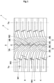
- FIG. 1 is a development showing a tread portion 2 of a tire 1 according to the present embodiment.
- the tire 1 according to the present embodiment is suitably used as a so-called tire for all seasons having the tread portion 2 suitable for running on road surfaces such as dry road surfaces, wet road surfaces, and snowy road surfaces.
- a pneumatic tire for a passenger car is presented as an example of the tire 1.
- the type of the tire 1 is not limited thereto.
- the tire 1 may be, for example, a pneumatic tire such as a heavy-duty tire, a tire for a motorcycle, or a racing tire, or a non-pneumatic tire the inside of which is not filled with pressurized air.
- the tread portion 2 in the present embodiment includes: at least one circumferential groove 3 continuously extending in a tire circumferential direction along a tire equator C; and a plurality of tilted grooves 4 continuously extending from the circumferential groove 3 to tread ends Te.
- Such a tread portion 2 improves drainage performance by the circumferential groove 3 and the tilted grooves 4, whereby the braking performance on a wet road surface of the tire 1 can be improved.
- each of the tread ends Te is, in the case of a pneumatic tire, an outermost ground contact position in a tire axial direction when: a normal load is applied to the tire 1 in a normal state; and the tire 1 is brought into contact with a flat surface at a camber angle of 0°.
- the center position in the tire axial direction between the tread ends Te is the tire equator C.
- the "normal state” refers to a state where: the tire 1 is mounted to a normal rim and adjusted to have a normal internal pressure; and no load is applied to the tire 1.
- dimensions and the like of each component of the tire 1 are values measured in the normal state, unless otherwise specified.
- the "normal rim” refers to a rim that is defined, in a standard system including a standard on which the tire 1 is based, by the standard for each tire.
- the "normal rim” is, for example, the “standard rim” in the JATMA standard, the “Design Rim” in the TRA standard, or the “Measuring Rim” in the ETRTO standard.
- the "normal internal pressure” refers to an air pressure that is defined, in a standard system including a standard on which the tire 1 is based, by the standard for each tire.
- the "normal internal pressure” is the “maximum air pressure” in the JATMA standard, the maximum value indicated in the table “TIRE LOAD LIMITS AT VARIOUS COLD INFLATION PRESSURES" in the TRA standard, or the “INFLATION PRESSURE” in the ETRTO standard.
- the "normal load” refers to a load that is defined, in a standard system including a standard on which the tire 1 is based, by the standard for each tire.
- the "normal load” is the “maximum load capacity” in the JATMA standard, the maximum value indicated in the table “TIRE LOAD LIMITS AT VARIOUS COLD INFLATION PRESSURES" in the TRA standard, or the “LOAD CAPACITY” in the ETRTO standard.
- the term “along” i.e., along a certain direction
- the term encompasses the meaning that many components in a direction different from the said direction are included locally.
- the tread portion 2 in the present embodiment further includes a plurality of blocks 5 each delimited by the circumferential groove 3, corresponding ones of the tilted grooves 4, and a corresponding one of the tread ends Te.
- Such blocks 5 have high rigidities in the tire axial direction and can improve the braking performance on each of a dry road surface and a wet road surface of the tire 1.
- Each of the plurality of blocks 5 in the present embodiment has a plurality of sipes 6 extending along the tilted grooves 4. Such a block 5 can improve the on-snow performance of the tire 1 by the edge effect of the sipes 6.
- each of the sipes 6 in the present specification means a slit having a width W1, not larger than 1.0 mm, in a direction perpendicular to a longitudinal direction.
- FIG. 2 is an enlarged view of the block 5 in the present embodiment.
- the plurality of sipes 6 desirably at least include: at least one first sipe 6A located on the tire equator C side; and at least one second sipe 6B located on the tread end Te side.
- the sipes 6 in the present embodiment further include at least one third sipe 6C located between the first sipe 6A and the second sipe 6B in the tire axial direction.
- a plurality of break portions 7 are present between the plurality of sipes 6, and thus such sipes 6 suppress decrease in the rigidity of the block 5, whereby the braking performance on each of a dry road surface and a wet road surface of the tire 1 can be improved.
- an end 6a on the tread end Te side of the third sipe 6C is located on an extension line of the second sipe 6B.
- Such sipes 6 enable exhibition of a greater edge effect through cooperation between the second sipe 6B and the third sipe 6C without decreasing the rigidity of the block 5, whereby the on-snow performance of the tire 1 can be improved.
- the tire 1 according to the present embodiment can attain both braking performance on each of a dry road surface and a wet road surface and on-snow performance.
- the tread portion 2 is formed from a tread rubber having a rubber hardness of 60 to 70° as shown in FIG. 1 .
- a tread portion 2 contributes to attaining both rigidity and ground contact performance in a balanced manner and attaining both braking performance on each of a dry road surface and a wet road surface and on-snow performance.
- the rubber hardness of the tread portion 2 is a hardness measured with a type A durometer in an environment at room temperature in accordance with JIS-K6253.
- the circumferential groove 3 in the present embodiment continuously extends in a zigzag manner in the tire circumferential direction.
- the circumferential groove 3 includes, for example, first circumferential groove portions 3A tilted to one side from the tire equator C and second circumferential groove portions 3B tilted, from the tire equator C, to a side opposite to the side to which the first circumferential groove portions 3A are tilted.
- the first circumferential groove portions 3A and the second circumferential groove portions 3B are repeatedly arranged in the tire circumferential direction. Consequently, snow column shearing force can be exerted in the tire circumferential direction and the tire axial direction, whereby the on-snow performance of the tire 1 can be improved.
- the circumferential groove 3 a case where the first circumferential groove portions 3A and the second circumferential groove portions 3B include many components in the tire axial direction, is desirably encompassed. That is, the circumferential groove 3 in the present embodiment extends along the tire circumferential direction as a whole by repeatedly arranging the first circumferential groove portions 3A and the second circumferential groove portions 3B in the tire circumferential direction.
- the form of the circumferential groove 3 is not limited to such a form.
- the circumferential groove 3 may extend linearly on the tire equator C, or a pair of the circumferential grooves 3 may be provided along the tire equator C.
- a groove width W2 of the circumferential groove 3 is preferably 4.0 to 7.0 mm. If the groove width W2 of the circumferential groove 3 is not smaller than 4.0 mm, drainage performance is improved, whereby the braking performance on a wet road surface of the tire 1 can be improved. From such a viewpoint, the groove width W2 of the circumferential groove 3 is more preferably not smaller than 4.5 mm.
- the groove width W2 of the circumferential groove 3 is not larger than 7.0 mm, decrease in rigidity near the tire equator C is suppressed, whereby the braking performance on a dry road surface of the tire 1 can be improved.
- the groove width W2 of the circumferential groove 3 is more preferably not larger than 6.0 mm. If the groove width W2 of the circumferential groove 3 varies in the longitudinal direction, the average value of the varying groove width is obtained as the groove width W2 of the circumferential groove 3.
- a groove depth D1 of the circumferential groove 3 is preferably 4.0 to 8.0 mm. If the groove depth D1 of the circumferential groove 3 is not smaller than 4.0 mm, drainage performance is improved, whereby the braking performance on a wet road surface of the tire 1 can be improved. From such a viewpoint, the groove depth D1 of the circumferential groove 3 is more preferably not smaller than 5.0 mm.
- the groove depth D1 of the circumferential groove 3 is not larger than 8.0 mm, decrease in rigidity near the tire equator C is suppressed, whereby the braking performance on a dry road surface of the tire 1 can be improved.
- the groove depth D1 of the circumferential groove 3 is more preferably not larger than 7.0 mm. If the groove depth D1 of the circumferential groove 3 varies in the longitudinal direction, the average value of the varying groove depth is obtained as the groove depth D1 of the circumferential groove 3.
- a groove width W3 of each tilted groove 4 is preferably 4.0 to 7.0 mm. If the groove width W3 of the tilted groove 4 is not smaller than 4.0 mm, drainage performance is improved, whereby the braking performance on a wet road surface of the tire 1 can be improved. From such a viewpoint, the groove width W3 of the tilted groove 4 is more preferably not smaller than 4.5 mm.
- the groove width W3 of the tilted groove 4 is not larger than 7.0 mm, decrease in the rigidity of the block 5 is suppressed, whereby the braking performance on a dry road surface of the tire 1 can be improved.
- the groove width W3 of the tilted groove 4 is more preferably not larger than 6.0 mm. If the groove width W3 of the tilted groove 4 varies in the longitudinal direction, the average value of the varying groove width is obtained as the groove width W3 of the tilted groove 4.
- a groove depth D2 of the tilted groove 4 is preferably 4.0 to 8.0 mm. If the groove depth D2 of the tilted groove 4 is not smaller than 4.0 mm, drainage performance is improved, whereby the braking performance on a wet road surface of the tire 1 can be improved. From such a viewpoint, the groove depth D2 of the tilted groove 4 is more preferably not smaller than 5.0 mm.
- the groove depth D2 of the tilted groove 4 is not larger than 8.0 mm, decrease in the rigidity of the block 5 is suppressed, whereby the braking performance on a dry road surface of the tire 1 can be improved.
- the groove depth D2 of the tilted groove 4 is more preferably not larger than 7.0 mm. If the groove depth D2 of the tilted groove 4 varies in the longitudinal direction, the average value of the varying groove depth is obtained as the groove depth D2 of the tilted groove 4.
- the tilted grooves 4 desirably include: a plurality of first tilted grooves 4A extending to one side in the tire axial direction relative to the tire equator C; and a plurality of second tilted grooves 4B extending to another side in the tire axial direction relative to the tire equator C so as to be tilted in a direction opposite to a direction in which each of the first tilted grooves 4A is tilted.
- Such tilted grooves 4 attain favorable balance in the tire axial direction and contribute to improving the braking performance on each of a dry road surface and a wet road surface of the tire 1.
- Each of the first tilted grooves 4A is provided on, for example, an extension line of a corresponding one of the first circumferential groove portions 3A.
- Each of the second tilted grooves 4B is provided on, for example, an extension line of a corresponding one of the second circumferential groove portions 3B.
- Such a tread portion 2 can improve drainage performance through cooperation between the circumferential groove 3 and the tilted grooves 4, whereby the braking performance on a wet road surface of the tire 1 can be improved.
- Each of the first tilted groove 4A and the second tilted groove 4B in the present embodiment includes: a crown tilted portion 4a on the tire equator C side; a shoulder tilted portion 4b on the corresponding tread end Te side; and a middle tilted portion 4c between the crown tilted portion 4a and the shoulder tilted portion 4b.
- Each of the crown tilted portion 4a, the shoulder tilted portion 4b, and the middle tilted portion 4c extends linearly, for example.
- the shoulder tilted portion 4b extends in the tire axial direction, for example.
- the rigidity in the tire circumferential direction of such a tilted groove 4 can easily be set, and the tilted groove 4 contributes to improving the braking performance on each of a dry road surface and a wet road surface of the tire 1.
- the form of the tilted groove 4 is not limited to such a form.
- the tilted groove 4 may be smoothly curved from the crown tilted portion 4a to the shoulder tilted portion 4b.
- the blocks 5 in the present embodiment include: first blocks 5A delimited by the first tilted grooves 4A; and second blocks 5B delimited by the second tilted grooves 4B.
- the first blocks 5A and the second blocks 5B in the present embodiment are arranged in the tire circumferential direction in a staggered pattern. Such blocks 5 attain favorable balance in the tire axial direction and contribute to improving the braking performance on each of a dry road surface and a wet road surface.
- Pitch numbers which are the numbers of the first blocks 5A and the second blocks 5B arranged in the tire circumferential direction are desirably equal to each other.
- Each of the pitch numbers of the first blocks 5A and the second blocks 5B is preferably 70 to 90. If the pitch number of the blocks 5 is not smaller than 70, adequate drainage performance can be maintained, whereby the braking performance on a wet road surface of the tire 1 can be improved. From such a viewpoint, the pitch number of the blocks 5 is more preferably not smaller than 75.
- the tread portion 2 can be maintained to have an adequate rigidity, whereby the braking performance on each of a dry road surface and a wet road surface of the tire 1 can be improved.
- the pitch number of the blocks 5 is more preferably not larger than 85.
- a land ratio of the tread portion 2 is preferably 60% to 75%.
- the land ratio is the proportion of the sum of the surface areas of the plurality of blocks 5 to the total surface area of the tread portion 2 in a state where all of the circumferential groove 3 and the tilted grooves 4 are filled. If the land ratio of the tread portion 2 is not lower than 60%, the tread portion 2 can be maintained to have an adequate rigidity, whereby the braking performance on each of a dry road surface and a wet road surface of the tire 1 can be improved. From such a viewpoint, the land ratio of the tread portion 2 is more preferably not lower than 65%.
- the land ratio of the tread portion 2 is not higher than 75%, an adequate drainage performance can be maintained, whereby the braking performance on a wet road surface of the tire 1 can be improved.
- the land ratio of the tread portion 2 is more preferably not higher than 70%.
- Each of the blocks 5 may be provided with, for example, a narrow groove 8 penetrating the block in the tire circumferential direction.
- the narrow groove 8 desirably has a groove depth D3 smaller than the groove depth D2 of each of the tilted grooves 4.
- the groove depth D3 of the narrow groove 8 is preferably 20% to 30% of the groove depth D2 of the tilted groove 4.
- Such a narrow groove 8 enables exhibition of the edge effect in the tire axial direction while maintaining the rigidity in the tire circumferential direction, and thus contributes to allowing the tire 1 to attain both braking performance on each of a dry road surface and a wet road surface and on-snow performance.
- the narrow groove 8 in the present specification means a groove having a groove width W4 of 2.0 to 3.0 mm and is distinguished from the circumferential groove 3, the tilted groove 4, and the sipe 6.
- the narrow groove 8 in the present embodiment allows the corresponding middle tilted portions 4c to be in communication with each other.
- the form of the narrow groove 8 is not limited to such a form.
- the narrow groove 8 may allow the corresponding shoulder tilted portions 4b to be in communication with each other or may allow the corresponding shoulder tilted portion 4b and the corresponding middle tilted portion 4c to be in communication with each other.
- the sipe 6 desirably extends inward in a tire radial direction so as to be bent in a zigzag manner in the tire circumferential direction, although not shown.
- the sipe 6 may have, for example, a three-dimensional shape as in a so-called Miura fold structure.
- Such a sipe 6 enables exhibition of the edge effect while maintaining the rigidity of the block 5, and thus contributes to allowing the tire 1 to attain both braking performance on each of a dry road surface and a wet road surface and on-snow performance.
- a depth D4 of the sipe 6 is preferably 4.0 to 8.0 mm. If the depth D4 of the sipe 6 is not smaller than 4.0 mm, the edge effect can be assuredly exhibited, whereby the on-snow performance of the tire 1 can be improved. From such a viewpoint, the depth D4 of the sipe 6 is more preferably not smaller than 4.5 mm.
- the depth D4 of the sipe 6 is not larger than 8.0 mm, the rigidity of the block 5 is inhibited from being excessively decreased, whereby the braking performance on each of a dry road surface and a wet road surface of the tire 1 can be improved.
- the depth D4 of the sipe 6 is more preferably not larger than 7.5 mm.
- the width W1 of the sipe 6 is preferably 0.2 to 0.8 mm. If the width W1 of the sipe 6 is not smaller than 0.2 mm, the edge effect can be assuredly exhibited, whereby the on-snow performance of the tire 1 can be improved. From such a viewpoint, the width W1 of the sipe 6 is more preferably not smaller than 0.3 mm.
- the width W1 of the sipe 6 is not larger than 0.8 mm, the rigidity of the block 5 is inhibited from being excessively decreased, whereby the braking performance on each of a dry road surface and a wet road surface of the tire 1 can be improved.
- the width W1 of the sipe 6 is more preferably not larger than 0.5 mm.
- Each of the break portions 7 between the corresponding sipes 6 has a length L1 that is preferably 2 to 6 mm. If the length L1 of the break portion 7 is not smaller than 2 mm, the rigidity of the block 5 can be improved, whereby the braking performance on each of a dry road surface and a wet road surface of the tire 1 can be improved. From such a viewpoint, the length L1 of the break portion 7 is more preferably not smaller than 3 mm.
- the length L1 of the break portion 7 is not larger than 6 mm, the lengths of the sipes 6 can be ensured, and thus the break portion 7 contributes to improving the on-snow performance of the tire 1. From such a viewpoint, the length L1 of the break portion 7 is more preferably not larger than 5 mm.
- the number of the break portions 7 provided per block 5 is preferably 2 to 6. Such a block 5 enables exhibition of the edge effect while maintaining the rigidity, whereby the tire 1 can attain both braking performance on each of a dry road surface and a wet road surface and on-snow performance. From such a viewpoint, the number of the break portions 7 is more preferably 2 to 4.
- the sipes 6 in the present embodiment further include at least one fourth sipe 6D located between the first sipe 6A and the third sipe 6C in the tire axial direction.
- Each of the plurality of blocks 5 in the present embodiment has one first sipe 6A, one second sipe 6B, one third sipe 6C, and one fourth sipe 6D.
- Such a block 5 enables exhibition of the edge effect of the sipes 6 while inhibiting excessive decrease in rigidity, whereby the tire 1 can attain both braking performance on each of a dry road surface and a wet road surface and on-snow performance.
- the first sipe 6A is desirably in communication with the circumferential groove 3. Such a first sipe 6A makes it possible to more prominently exhibit the edge effect near the tire equator C, whereby the on-snow performance of the tire 1 can be improved.
- the first sipe 6A in the present embodiment extends linearly along the first circumferential groove portion 3A and the crown tilted portion 4a. Such a first sipe 6A is easy to form, whereby manufacturing cost can be decreased.
- the first sipe 6A has a length L2 that is preferably 10 to 25 mm. If the length L2 of the first sipe 6A is not smaller than 10 mm, the edge effect can be assuredly exhibited, whereby the on-snow performance of the tire 1 can be improved. From such a viewpoint, the length L2 of the first sipe 6A is more preferably not smaller than 15 mm.
- the length L2 of the first sipe 6A is not larger than 25 mm, the rigidity of the block 5 is inhibited from being excessively decreased, whereby the braking performance on each of a dry road surface and a wet road surface of the tire 1 can be improved.
- the length L2 of the first sipe 6A is more preferably not larger than 20 mm.
- the second sipe 6B is desirably in communication with the tread end Te. Such a second sipe 6B facilitates deformation in the tire circumferential direction of the block 5 near the tread end Te. Consequently, frictional force upon braking can be improved, whereby the braking performance on each of a dry road surface and a wet road surface of the tire 1 can be improved.
- the second sipe 6B in the present embodiment extends linearly along the shoulder tilted portion 4b. Such a second sipe 6B is easy to form, whereby manufacturing cost can be decreased.
- the second sipe 6B desirably extends on a center line in the tire circumferential direction of the block 5. Such a second sipe 6B enables the rigidity of the block 5 to be equal between both sides in the tire circumferential direction of the second sipe 6B, whereby the braking performance on a dry road surface of the tire 1 can be improved.
- the second sipe 6B has a length L3 that is preferably 5 to 12 mm.
- the length to the tread end Te is measured as the length L3 of the second sipe 6B.
- the length L3 of the second sipe 6B is not smaller than 5 mm, the edge effect can be assuredly exhibited, whereby the on-snow performance of the tire 1 can be improved. From such a viewpoint, the length L3 of the second sipe 6B is more preferably not smaller than 7 mm.
- the length L3 of the second sipe 6B is not larger than 12 mm, the rigidity of the block 5 is inhibited from being excessively decreased, whereby the braking performance on each of a dry road surface and a wet road surface of the tire 1 can be improved.
- the length L3 of the second sipe 6B is more preferably not larger than 10 mm.
- the third sipe 6C in the present embodiment extends in the longitudinal direction so as to be bent along the shoulder tilted portion 4b and the middle tilted portion 4c. Such a third sipe 6C enables exhibition of the edge effect in the tire circumferential direction and the tire axial direction, whereby the on-snow performance of the tire 1 can be improved.
- the third sipe 6C contributes to allowing the tire 1 to attain both braking performance on each of a dry road surface and a wet road surface and on-snow performance by adjusting, as appropriate, a ratio (L4/L5) of a length L4 of the third sipe 6C at a portion thereof extending along the shoulder tilted portion 4b to a length L5 of the third sipe 6C at a portion thereof extending along the middle tilted portion 4c. From such a viewpoint, the ratio (L4/L5) is preferably 50% to 100%.
- a length (L4+L5) along the longitudinal direction of the third sipe 6C is preferably 20 to 40 mm. If the length (L4+L5) of the third sipe 6C is not smaller than 20 mm, the edge effect can be assuredly exhibited, whereby the on-snow performance of the tire 1 can be more improved. From such a viewpoint, the length (L4+L5) of the third sipe 6C is more preferably not smaller than 25 mm.
- the length (L4+L5) of the third sipe 6C is not larger than 40 mm, the rigidity of the block 5 is inhibited from being excessively decreased, whereby the braking performance on each of a dry road surface and a wet road surface of the tire 1 can be improved.
- the length (L4+L5) of the third sipe 6C is more preferably not larger than 35 mm.
- the fourth sipe 6D in the present embodiment extends in the longitudinal direction so as to be bent along the crown tilted portion 4a and the middle tilted portion 4c. Such a fourth sipe 6D enables exhibition of the edge effect in the tire circumferential direction and the tire axial direction, whereby the on-snow performance of the tire 1 can be improved.
- the fourth sipe 6D contributes to allowing the tire 1 to attain both braking performance on each of a dry road surface and a wet road surface and on-snow performance by adjusting, as appropriate, a ratio (L6/L7) of a length L6 of the fourth sipe 6D at a portion thereof extending along the crown tilted portion 4a to a length L7 of the fourth sipe 6D at a portion thereof extending along the middle tilted portion 4c. From such a viewpoint, the ratio (L6/L7) is preferably 100% to 250%.
- a length (L6+L7) along the longitudinal direction of the fourth sipe 6D is preferably 25 to 50 mm.
- Such a fourth sipe 6D enables exhibition of the edge effect of the sipes 6 while inhibiting excessive decrease in rigidity, and thus contributes to allowing the tire 1 to attain both braking performance on each of a dry road surface and a wet road surface and on-snow performance.
- the length (L6+L7) of the fourth sipe 6D is more preferably 30 to 45 mm.
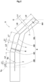
- FIG. 3 is an enlarged view of a block 10 in a second embodiment.
- the block 10 in the second embodiment has an external shape corresponding to a circumferential groove 3 (see FIG. 1 ) extending linearly on the tire equator C.
- the outer shape of the block 10 may be, for example, the same as the shape of the above block 5 corresponding to the circumferential groove 3 extending in a zigzag manner along the tire equator C.
- a plurality of the blocks 10 are desirably arranged in the tire circumferential direction in the same manner as the above blocks 5.
- Each of the plurality of blocks 10 in the second embodiment has a plurality of sipes 11 extending along the tilted grooves 4 (shown in FIG. 1 ) in the same manner as the above block 5.
- Such a block 10 can improve the on-snow performance of the tire 1 by the edge effect of the sipes 11.
- the plurality of sipes 11 in the second embodiment include: a plurality of first sipes 11A located on the tire equator C side; and at least one second sipe 11B located on the tread end Te side.
- the number of the first sipes 11A is desirably larger than the number of the second sipes 11B.
- the rigidity thereof on the tire equator C side is lower than the rigidity thereof on the tread end Te side. This can improve follow-up performance, to a road surface, on the tire equator C side on which significant influence is inflicted on the braking performance.
- the edge effect of the sipes 11 on the tire equator C side is significant, whereby the on-snow performance of the tire 1 can be more improved.
- the plurality of sipes 11 in the second embodiment include two first sipes 11A, one second sipe 11B, one third sipe 11C, and one fourth sipe 11D.
- the shapes and the positions of the second sipe 11B, the third sipe 11C, and the fourth sipe 11D are respectively the same as those of the second sipe 6B, the third sipe 6C, and the fourth sipe 6D described above, and descriptions thereof will be omitted.
- Such a block 10 enables exhibition of the edge effect of the sipes 11 while inhibiting excessive decrease in rigidity as a whole, whereby the tire 1 can attain both braking performance on each of a dry road surface and a wet road surface and on-snow performance.
- a plurality of the second sipes 11B, the third sipes 11C, and the fourth sipes 11D may also be provided in the same manner as the above first sipes 11A, for example.
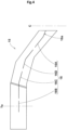
- FIG. 4 is an enlarged view of a block 15 in a third embodiment. As shown in FIG. 4 , the shapes and the arrangement of the blocks 15 in the third embodiment are the same as those of the above blocks 10 in the second embodiment, and descriptions thereof will be omitted.
- Each of a plurality of the blocks 15 in the third embodiment has a plurality of sipes 16 extending along the tilted grooves 4 (shown in FIG. 1 ) in the same manner as the above block 5.
- Such a block 15 can improve the on-snow performance of the tire 1 by the edge effect of the sipes 16.
- the plurality of sipes 16 in the third embodiment include one first sipe 16A, one second sipe 16B, one third sipe 16C, and one fourth sipe 16D.
- Such a block 15 enables exhibition of the edge effect of the sipes 16 while inhibiting excessive decrease in rigidity, whereby the tire 1 can attain both braking performance on each of a dry road surface and a wet road surface and on-snow performance.
- the first sipe 16A in the third embodiment extends in the longitudinal direction such that an end portion 16a thereof on the tire equator C side is bent.
- the end portion 16a of the first sipe 16A is desirably bent in the tire axial direction.
- Such a first sipe 16A can increase the edge effect in the tire circumferential direction on the tire equator C side, whereby the tire 1 can attain both braking performance on each of a dry road surface and a wet road surface and on-snow performance.
- the shapes and the positions of the second sipe 16B, the third sipe 16C, and the fourth sipe 16D are respectively the same as those of the second sipe 6B, the third sipe 6C, and the fourth sipe 6D described above, and descriptions thereof will be omitted.
- FIG. 5 is an enlarged view of a block 20 in a fourth embodiment. As shown in FIG. 5 , the shapes and the arrangement of the blocks 20 in the fourth embodiment are the same as those of the above blocks 10 in the second embodiment, and descriptions thereof will be omitted.
- Each of a plurality of the blocks 20 in the fourth embodiment has a plurality of sipes 21 extending along the tilted grooves 4 (shown in FIG. 1 ) in the same manner as the above block 5.
- Such a block 20 can improve the on-snow performance of the tire 1 by the edge effect of the sipes 21.
- the plurality of sipes 21 in the fourth embodiment include one first sipe 21A, one second sipe 21B, one third sipe 21C, and one fourth sipe 21D.
- Such a block 20 enables exhibition of the edge effect of the sipes 21 while inhibiting excessive decrease in rigidity, whereby the tire 1 can attain both braking performance on each of a dry road surface and a wet road surface and on-snow performance.
- the fourth embodiment employs a so-called interlocking structure in which an end portion 21a of the first sipe 21A and an end portion 21b of the fourth sipe 21D match up with each other through a plurality of bent portions thereof. Likewise, an end portion 21c of the third sipe 21C and another end portion 21d of the fourth sipe 21D also desirably match up with each other through a plurality of bent portions thereof.
- Such sipes 21 make it possible to suppress deformation of the block 20 in the tire circumferential direction while improving the edge effect in the tire circumferential direction and the tire axial direction, by the bent portions. Therefore, the block 20 in the fourth embodiment enables the tire 1 to attain both braking performance on each of a dry road surface and a wet road surface and on-snow performance.
- Tires each having the tread pattern shown in FIG. 1 were produced as samples on the basis of specifications in Table 1. By using each of the tires produced as samples, the braking performance on a dry road surface, the braking performance on a wet road surface, and the on-snow performance of the tire were tested. Main common specifications and test methods are as follows.
- Each set of test tires was mounted on all the wheels of the test vehicle.
- a test of measuring the distance run until the test vehicle had stopped from 100 km per hour was performed ten times on a test course having a dry road surface.
- the average of the distances obtained in the ten times of tests was calculated.
- the result of the calculation is indicated as an index with the result of comparative example 1 being regarded as 100.
- a larger numerical value indicates a better braking performance on the dry road surface.
- Each set of test tires was mounted on all the wheels of the test vehicle.
- a test of measuring the distance run until the test vehicle had stopped from 80 km per hour was performed ten times on a test course having a wet road surface.
- the average of the distances obtained in the ten times of tests was calculated.
- the result of the calculation is indicated as an index with the result of comparative example 1 being regarded as 100.
- a larger numerical value indicates a better braking performance on the wet road surface.
- Each set of test tires was mounted on all the wheels of the test vehicle.
- a test of measuring the distance run when the test vehicle had accelerated to 40 km per hour from a stopped state was performed ten times on a test course having a snowy road surface.
- the average of the distances obtained in the ten times of tests was calculated.
- the result of the calculation is indicated as an index with the result of comparative example 1 being regarded as 100.
- a larger numerical value indicates a better on-snow performance.
- each of the tires in the examples has a better braking performance on each of the dry road surface and the wet road surface than the tires in the comparative examples and ensures an on-snow performance equivalent to those of the tires in the comparative examples, it has been confirmed that each of the tires in the examples attains both braking performance on each of a dry road surface and a wet road surface and on-snow performance.
- the present disclosure is as follows.
- a tire including a tread portion, the tread portion including:
- each of the plurality of blocks has a plurality of the first sipes.
- sipes further include at least one fourth sipe located between the first sipe and the third sipe in the tire axial direction.
- each of the sipes extends inward in a tire radial direction so as to be bent in a zigzag manner in the tire circumferential direction.
Landscapes
- Engineering & Computer Science (AREA)
- Mechanical Engineering (AREA)
- Tires In General (AREA)
Abstract
Description
- The present disclosure relates to a tire having a tread portion including a plurality of blocks.
- Conventionally, tires each having a tread portion including a plurality of blocks have been known. For example,
Japanese Laid-Open Patent Publication No. 2016-199120 - However, in the tire in
Japanese Laid-Open Patent Publication No. 2016-199120 - The present disclosure has been made in view of the above circumstances, and a main object of the present disclosure is to provide a tire that can attain both braking performance on each of a dry road surface and a wet road surface and on-snow performance.
- The present disclosure is directed to a tire having a tread portion, the tread portion including: at least one circumferential groove continuously extending in a tire circumferential direction along a tire equator; a plurality of tilted grooves continuously extending from the circumferential groove to tread ends; and a plurality of blocks each delimited by the circumferential groove, corresponding ones of the tilted grooves, and a corresponding one of the tread ends, wherein each of the plurality of blocks has a plurality of sipes extending along the tilted grooves, the plurality of sipes at least include at least one first sipe located on the tire equator side, at least one second sipe located on the tread end side, and at least one third sipe located between the first sipe and the second sipe in a tire axial direction, and an end on the tread end side of the third sipe is located on an extension line of the second sipe.
- Since the tire according to the present disclosure has the above configuration, the tire can attain both braking performance on each of a dry road surface and a wet road surface and on-snow performance.
-
-
FIG. 1 is a development showing a tread portion of a tire according to an embodiment of the present disclosure; -
FIG. 2 is an enlarged view of a block in the present embodiment; -
FIG. 3 is an enlarged view of a block in a second embodiment; -
FIG. 4 is an enlarged view of a block in a third embodiment; and -
FIG. 5 is an enlarged view of a block in a fourth embodiment. - Hereinafter, an embodiment of the present disclosure will be described in detail with reference to the drawings.
-
FIG. 1 is a development showing atread portion 2 of atire 1 according to the present embodiment. As shown inFIG. 1 , thetire 1 according to the present embodiment is suitably used as a so-called tire for all seasons having thetread portion 2 suitable for running on road surfaces such as dry road surfaces, wet road surfaces, and snowy road surfaces. - In the present embodiment, a pneumatic tire for a passenger car is presented as an example of the
tire 1. However, the type of thetire 1 is not limited thereto. Thetire 1 may be, for example, a pneumatic tire such as a heavy-duty tire, a tire for a motorcycle, or a racing tire, or a non-pneumatic tire the inside of which is not filled with pressurized air. - The
tread portion 2 in the present embodiment includes: at least onecircumferential groove 3 continuously extending in a tire circumferential direction along a tire equator C; and a plurality oftilted grooves 4 continuously extending from thecircumferential groove 3 to tread ends Te. Such atread portion 2 improves drainage performance by thecircumferential groove 3 and thetilted grooves 4, whereby the braking performance on a wet road surface of thetire 1 can be improved. - Here, each of the tread ends Te is, in the case of a pneumatic tire, an outermost ground contact position in a tire axial direction when: a normal load is applied to the
tire 1 in a normal state; and thetire 1 is brought into contact with a flat surface at a camber angle of 0°. The center position in the tire axial direction between the tread ends Te is the tire equator C. - The "normal state" refers to a state where: the
tire 1 is mounted to a normal rim and adjusted to have a normal internal pressure; and no load is applied to thetire 1.
Hereinafter, dimensions and the like of each component of thetire 1 are values measured in the normal state, unless otherwise specified. - The "normal rim" refers to a rim that is defined, in a standard system including a standard on which the
tire 1 is based, by the standard for each tire. The "normal rim" is, for example, the "standard rim" in the JATMA standard, the "Design Rim" in the TRA standard, or the "Measuring Rim" in the ETRTO standard. - The "normal internal pressure" refers to an air pressure that is defined, in a standard system including a standard on which the
tire 1 is based, by the standard for each tire. The "normal internal pressure" is the "maximum air pressure" in the JATMA standard, the maximum value indicated in the table "TIRE LOAD LIMITS AT VARIOUS COLD INFLATION PRESSURES" in the TRA standard, or the "INFLATION PRESSURE" in the ETRTO standard. - The "normal load" refers to a load that is defined, in a standard system including a standard on which the
tire 1 is based, by the standard for each tire. The "normal load" is the "maximum load capacity" in the JATMA standard, the maximum value indicated in the table "TIRE LOAD LIMITS AT VARIOUS COLD INFLATION PRESSURES" in the TRA standard, or the "LOAD CAPACITY" in the ETRTO standard. - In the present specification, the term "along " (i.e., along a certain direction) means that many components in the direction are included as a whole, and the term encompasses the meaning that many components in a direction different from the said direction are included locally.
- The
tread portion 2 in the present embodiment further includes a plurality ofblocks 5 each delimited by thecircumferential groove 3, corresponding ones of thetilted grooves 4, and a corresponding one of the tread ends Te.Such blocks 5 have high rigidities in the tire axial direction and can improve the braking performance on each of a dry road surface and a wet road surface of thetire 1. - Each of the plurality of
blocks 5 in the present embodiment has a plurality ofsipes 6 extending along thetilted grooves 4. Such ablock 5 can improve the on-snow performance of thetire 1 by the edge effect of thesipes 6. Here, each of thesipes 6 in the present specification means a slit having a width W1, not larger than 1.0 mm, in a direction perpendicular to a longitudinal direction. -
FIG. 2 is an enlarged view of theblock 5 in the present embodiment. As shown inFIG. 2 , the plurality ofsipes 6 desirably at least include: at least onefirst sipe 6A located on the tire equator C side; and at least onesecond sipe 6B located on the tread end Te side. Thesipes 6 in the present embodiment further include at least onethird sipe 6C located between thefirst sipe 6A and thesecond sipe 6B in the tire axial direction. - A plurality of
break portions 7 are present between the plurality ofsipes 6, and thussuch sipes 6 suppress decrease in the rigidity of theblock 5, whereby the braking performance on each of a dry road surface and a wet road surface of thetire 1 can be improved. - In the present embodiment, an
end 6a on the tread end Te side of thethird sipe 6C is located on an extension line of thesecond sipe 6B.Such sipes 6 enable exhibition of a greater edge effect through cooperation between thesecond sipe 6B and thethird sipe 6C without decreasing the rigidity of theblock 5, whereby the on-snow performance of thetire 1 can be improved. Thus, thetire 1 according to the present embodiment can attain both braking performance on each of a dry road surface and a wet road surface and on-snow performance. - In a more preferable mode, the
tread portion 2 is formed from a tread rubber having a rubber hardness of 60 to 70° as shown inFIG. 1 . Such atread portion 2 contributes to attaining both rigidity and ground contact performance in a balanced manner and attaining both braking performance on each of a dry road surface and a wet road surface and on-snow performance. Here, the rubber hardness of thetread portion 2 is a hardness measured with a type A durometer in an environment at room temperature in accordance with JIS-K6253. - The
circumferential groove 3 in the present embodiment continuously extends in a zigzag manner in the tire circumferential direction. Thecircumferential groove 3 includes, for example, firstcircumferential groove portions 3A tilted to one side from the tire equator C and secondcircumferential groove portions 3B tilted, from the tire equator C, to a side opposite to the side to which the firstcircumferential groove portions 3A are tilted. - In such a
circumferential groove 3, the firstcircumferential groove portions 3A and the secondcircumferential groove portions 3B are repeatedly arranged in the tire circumferential direction. Consequently, snow column shearing force can be exerted in the tire circumferential direction and the tire axial direction, whereby the on-snow performance of thetire 1 can be improved. - For the
circumferential groove 3, a case where the firstcircumferential groove portions 3A and the secondcircumferential groove portions 3B include many components in the tire axial direction, is desirably encompassed. That is, thecircumferential groove 3 in the present embodiment extends along the tire circumferential direction as a whole by repeatedly arranging the firstcircumferential groove portions 3A and the secondcircumferential groove portions 3B in the tire circumferential direction. - The form of the
circumferential groove 3 is not limited to such a form. For example, thecircumferential groove 3 may extend linearly on the tire equator C, or a pair of thecircumferential grooves 3 may be provided along the tire equator C. - A groove width W2 of the
circumferential groove 3 is preferably 4.0 to 7.0 mm. If the groove width W2 of thecircumferential groove 3 is not smaller than 4.0 mm, drainage performance is improved, whereby the braking performance on a wet road surface of thetire 1 can be improved. From such a viewpoint, the groove width W2 of thecircumferential groove 3 is more preferably not smaller than 4.5 mm. - Meanwhile, if the groove width W2 of the
circumferential groove 3 is not larger than 7.0 mm, decrease in rigidity near the tire equator C is suppressed, whereby the braking performance on a dry road surface of thetire 1 can be improved. From such a viewpoint, the groove width W2 of thecircumferential groove 3 is more preferably not larger than 6.0 mm. If the groove width W2 of thecircumferential groove 3 varies in the longitudinal direction, the average value of the varying groove width is obtained as the groove width W2 of thecircumferential groove 3. - A groove depth D1 of the
circumferential groove 3 is preferably 4.0 to 8.0 mm.
If the groove depth D1 of thecircumferential groove 3 is not smaller than 4.0 mm, drainage performance is improved, whereby the braking performance on a wet road surface of thetire 1 can be improved. From such a viewpoint, the groove depth D1 of thecircumferential groove 3 is more preferably not smaller than 5.0 mm. - Meanwhile, if the groove depth D1 of the
circumferential groove 3 is not larger than 8.0 mm, decrease in rigidity near the tire equator C is suppressed, whereby the braking performance on a dry road surface of thetire 1 can be improved. From such a viewpoint, the groove depth D1 of thecircumferential groove 3 is more preferably not larger than 7.0 mm. If the groove depth D1 of thecircumferential groove 3 varies in the longitudinal direction, the average value of the varying groove depth is obtained as the groove depth D1 of thecircumferential groove 3. - A groove width W3 of each tilted
groove 4 is preferably 4.0 to 7.0 mm. If the groove width W3 of the tiltedgroove 4 is not smaller than 4.0 mm, drainage performance is improved, whereby the braking performance on a wet road surface of thetire 1 can be improved. From such a viewpoint, the groove width W3 of the tiltedgroove 4 is more preferably not smaller than 4.5 mm. - Meanwhile, if the groove width W3 of the tilted
groove 4 is not larger than 7.0 mm, decrease in the rigidity of theblock 5 is suppressed, whereby the braking performance on a dry road surface of thetire 1 can be improved. From such a viewpoint, the groove width W3 of the tiltedgroove 4 is more preferably not larger than 6.0 mm. If the groove width W3 of the tiltedgroove 4 varies in the longitudinal direction, the average value of the varying groove width is obtained as the groove width W3 of the tiltedgroove 4. - A groove depth D2 of the tilted
groove 4 is preferably 4.0 to 8.0 mm. If the groove depth D2 of the tiltedgroove 4 is not smaller than 4.0 mm, drainage performance is improved, whereby the braking performance on a wet road surface of thetire 1 can be improved. From such a viewpoint, the groove depth D2 of the tiltedgroove 4 is more preferably not smaller than 5.0 mm. - Meanwhile, if the groove depth D2 of the tilted
groove 4 is not larger than 8.0 mm, decrease in the rigidity of theblock 5 is suppressed, whereby the braking performance on a dry road surface of thetire 1 can be improved. From such a viewpoint, the groove depth D2 of the tiltedgroove 4 is more preferably not larger than 7.0 mm. If the groove depth D2 of the tiltedgroove 4 varies in the longitudinal direction, the average value of the varying groove depth is obtained as the groove depth D2 of the tiltedgroove 4. - The tilted
grooves 4 desirably include: a plurality of first tiltedgrooves 4A extending to one side in the tire axial direction relative to the tire equator C; and a plurality of second tiltedgrooves 4B extending to another side in the tire axial direction relative to the tire equator C so as to be tilted in a direction opposite to a direction in which each of the first tiltedgrooves 4A is tilted. Such tiltedgrooves 4 attain favorable balance in the tire axial direction and contribute to improving the braking performance on each of a dry road surface and a wet road surface of thetire 1. - Each of the first tilted
grooves 4A is provided on, for example, an extension line of a corresponding one of the firstcircumferential groove portions 3A. Each of the second tiltedgrooves 4B is provided on, for example, an extension line of a corresponding one of the secondcircumferential groove portions 3B. Such atread portion 2 can improve drainage performance through cooperation between thecircumferential groove 3 and the tiltedgrooves 4, whereby the braking performance on a wet road surface of thetire 1 can be improved. - Each of the first tilted
groove 4A and the second tiltedgroove 4B in the present embodiment includes: a crown tilted portion 4a on the tire equator C side; a shoulder tilted portion 4b on the corresponding tread end Te side; and a middle tilted portion 4c between the crown tilted portion 4a and the shoulder tilted portion 4b. - Each of the crown tilted portion 4a, the shoulder tilted portion 4b, and the middle tilted portion 4c extends linearly, for example. The shoulder tilted portion 4b extends in the tire axial direction, for example. The rigidity in the tire circumferential direction of such a tilted
groove 4 can easily be set, and the tiltedgroove 4 contributes to improving the braking performance on each of a dry road surface and a wet road surface of thetire 1. The form of the tiltedgroove 4 is not limited to such a form. For example, the tiltedgroove 4 may be smoothly curved from the crown tilted portion 4a to the shoulder tilted portion 4b. - The
blocks 5 in the present embodiment include:first blocks 5A delimited by the first tiltedgrooves 4A; andsecond blocks 5B delimited by the second tiltedgrooves 4B. Thefirst blocks 5A and thesecond blocks 5B in the present embodiment are arranged in the tire circumferential direction in a staggered pattern.Such blocks 5 attain favorable balance in the tire axial direction and contribute to improving the braking performance on each of a dry road surface and a wet road surface. - Pitch numbers which are the numbers of the
first blocks 5A and thesecond blocks 5B arranged in the tire circumferential direction are desirably equal to each other. Each of the pitch numbers of thefirst blocks 5A and thesecond blocks 5B is preferably 70 to 90. If the pitch number of theblocks 5 is not smaller than 70, adequate drainage performance can be maintained, whereby the braking performance on a wet road surface of thetire 1 can be improved. From such a viewpoint, the pitch number of theblocks 5 is more preferably not smaller than 75. - Meanwhile, if the pitch number of the
blocks 5 is not larger than 90, thetread portion 2 can be maintained to have an adequate rigidity, whereby the braking performance on each of a dry road surface and a wet road surface of thetire 1 can be improved. From such a viewpoint, the pitch number of theblocks 5 is more preferably not larger than 85. - A land ratio of the
tread portion 2 is preferably 60% to 75%. The land ratio is the proportion of the sum of the surface areas of the plurality ofblocks 5 to the total surface area of thetread portion 2 in a state where all of thecircumferential groove 3 and the tiltedgrooves 4 are filled. If the land ratio of thetread portion 2 is not lower than 60%, thetread portion 2 can be maintained to have an adequate rigidity, whereby the braking performance on each of a dry road surface and a wet road surface of thetire 1 can be improved. From such a viewpoint, the land ratio of thetread portion 2 is more preferably not lower than 65%. - Meanwhile, if the land ratio of the
tread portion 2 is not higher than 75%, an adequate drainage performance can be maintained, whereby the braking performance on a wet road surface of thetire 1 can be improved. From such a viewpoint, the land ratio of thetread portion 2 is more preferably not higher than 70%. - Each of the
blocks 5 may be provided with, for example, anarrow groove 8 penetrating the block in the tire circumferential direction. Thenarrow groove 8 desirably has a groove depth D3 smaller than the groove depth D2 of each of the tiltedgrooves 4. The groove depth D3 of thenarrow groove 8 is preferably 20% to 30% of the groove depth D2 of the tiltedgroove 4. - Such a
narrow groove 8 enables exhibition of the edge effect in the tire axial direction while maintaining the rigidity in the tire circumferential direction, and thus contributes to allowing thetire 1 to attain both braking performance on each of a dry road surface and a wet road surface and on-snow performance. Here, thenarrow groove 8 in the present specification means a groove having a groove width W4 of 2.0 to 3.0 mm and is distinguished from thecircumferential groove 3, the tiltedgroove 4, and thesipe 6. - The
narrow groove 8 in the present embodiment allows the corresponding middle tilted portions 4c to be in communication with each other. The form of thenarrow groove 8 is not limited to such a form. For example, thenarrow groove 8 may allow the corresponding shoulder tilted portions 4b to be in communication with each other or may allow the corresponding shoulder tilted portion 4b and the corresponding middle tilted portion 4c to be in communication with each other. - The
sipe 6 desirably extends inward in a tire radial direction so as to be bent in a zigzag manner in the tire circumferential direction, although not shown. Thesipe 6 may have, for example, a three-dimensional shape as in a so-called Miura fold structure. Such asipe 6 enables exhibition of the edge effect while maintaining the rigidity of theblock 5, and thus contributes to allowing thetire 1 to attain both braking performance on each of a dry road surface and a wet road surface and on-snow performance. - A depth D4 of the
sipe 6 is preferably 4.0 to 8.0 mm. If the depth D4 of thesipe 6 is not smaller than 4.0 mm, the edge effect can be assuredly exhibited, whereby the on-snow performance of thetire 1 can be improved. From such a viewpoint, the depth D4 of thesipe 6 is more preferably not smaller than 4.5 mm. - Meanwhile, if the depth D4 of the
sipe 6 is not larger than 8.0 mm, the rigidity of theblock 5 is inhibited from being excessively decreased, whereby the braking performance on each of a dry road surface and a wet road surface of thetire 1 can be improved. From such a viewpoint, the depth D4 of thesipe 6 is more preferably not larger than 7.5 mm. - As shown in
FIG. 2 , the width W1 of thesipe 6 is preferably 0.2 to 0.8 mm. If the width W1 of thesipe 6 is not smaller than 0.2 mm, the edge effect can be assuredly exhibited, whereby the on-snow performance of thetire 1 can be improved. From such a viewpoint, the width W1 of thesipe 6 is more preferably not smaller than 0.3 mm. - Meanwhile, if the width W1 of the
sipe 6 is not larger than 0.8 mm, the rigidity of theblock 5 is inhibited from being excessively decreased, whereby the braking performance on each of a dry road surface and a wet road surface of thetire 1 can be improved. From such a viewpoint, the width W1 of thesipe 6 is more preferably not larger than 0.5 mm. - Each of the
break portions 7 between thecorresponding sipes 6 has a length L1 that is preferably 2 to 6 mm. If the length L1 of thebreak portion 7 is not smaller than 2 mm, the rigidity of theblock 5 can be improved, whereby the braking performance on each of a dry road surface and a wet road surface of thetire 1 can be improved. From such a viewpoint, the length L1 of thebreak portion 7 is more preferably not smaller than 3 mm. - Meanwhile, if the length L1 of the
break portion 7 is not larger than 6 mm, the lengths of thesipes 6 can be ensured, and thus thebreak portion 7 contributes to improving the on-snow performance of thetire 1. From such a viewpoint, the length L1 of thebreak portion 7 is more preferably not larger than 5 mm. - The number of the
break portions 7 provided perblock 5 is preferably 2 to 6. Such ablock 5 enables exhibition of the edge effect while maintaining the rigidity, whereby thetire 1 can attain both braking performance on each of a dry road surface and a wet road surface and on-snow performance. From such a viewpoint, the number of thebreak portions 7 is more preferably 2 to 4. - The
sipes 6 in the present embodiment further include at least onefourth sipe 6D located between thefirst sipe 6A and thethird sipe 6C in the tire axial direction. Each of the plurality ofblocks 5 in the present embodiment has onefirst sipe 6A, onesecond sipe 6B, onethird sipe 6C, and onefourth sipe 6D. Such ablock 5 enables exhibition of the edge effect of thesipes 6 while inhibiting excessive decrease in rigidity, whereby thetire 1 can attain both braking performance on each of a dry road surface and a wet road surface and on-snow performance. - The
first sipe 6A is desirably in communication with thecircumferential groove 3. Such afirst sipe 6A makes it possible to more prominently exhibit the edge effect near the tire equator C, whereby the on-snow performance of thetire 1 can be improved. - The
first sipe 6A in the present embodiment extends linearly along the firstcircumferential groove portion 3A and the crown tilted portion 4a. Such afirst sipe 6A is easy to form, whereby manufacturing cost can be decreased. - The
first sipe 6A has a length L2 that is preferably 10 to 25 mm. If the length L2 of thefirst sipe 6A is not smaller than 10 mm, the edge effect can be assuredly exhibited, whereby the on-snow performance of thetire 1 can be improved. From such a viewpoint, the length L2 of thefirst sipe 6A is more preferably not smaller than 15 mm. - Meanwhile, if the length L2 of the
first sipe 6A is not larger than 25 mm, the rigidity of theblock 5 is inhibited from being excessively decreased, whereby the braking performance on each of a dry road surface and a wet road surface of thetire 1 can be improved. From such a viewpoint, the length L2 of thefirst sipe 6A is more preferably not larger than 20 mm. - The
second sipe 6B is desirably in communication with the tread end Te. Such asecond sipe 6B facilitates deformation in the tire circumferential direction of theblock 5 near the tread end Te. Consequently, frictional force upon braking can be improved, whereby the braking performance on each of a dry road surface and a wet road surface of thetire 1 can be improved. - The
second sipe 6B in the present embodiment extends linearly along the shoulder tilted portion 4b. Such asecond sipe 6B is easy to form, whereby manufacturing cost can be decreased. - The
second sipe 6B desirably extends on a center line in the tire circumferential direction of theblock 5. Such asecond sipe 6B enables the rigidity of theblock 5 to be equal between both sides in the tire circumferential direction of thesecond sipe 6B, whereby the braking performance on a dry road surface of thetire 1 can be improved. - The
second sipe 6B has a length L3 that is preferably 5 to 12 mm. Here, although thesecond sipe 6B extends beyond the tread end Te, the length to the tread end Te is measured as the length L3 of thesecond sipe 6B. - If the length L3 of the
second sipe 6B is not smaller than 5 mm, the edge effect can be assuredly exhibited, whereby the on-snow performance of thetire 1 can be improved. From such a viewpoint, the length L3 of thesecond sipe 6B is more preferably not smaller than 7 mm. - Meanwhile, if the length L3 of the
second sipe 6B is not larger than 12 mm, the rigidity of theblock 5 is inhibited from being excessively decreased, whereby the braking performance on each of a dry road surface and a wet road surface of thetire 1 can be improved. From such a viewpoint, the length L3 of thesecond sipe 6B is more preferably not larger than 10 mm. - The
third sipe 6C in the present embodiment extends in the longitudinal direction so as to be bent along the shoulder tilted portion 4b and the middle tilted portion 4c. Such athird sipe 6C enables exhibition of the edge effect in the tire circumferential direction and the tire axial direction, whereby the on-snow performance of thetire 1 can be improved. - The
third sipe 6C contributes to allowing thetire 1 to attain both braking performance on each of a dry road surface and a wet road surface and on-snow performance by adjusting, as appropriate, a ratio (L4/L5) of a length L4 of thethird sipe 6C at a portion thereof extending along the shoulder tilted portion 4b to a length L5 of thethird sipe 6C at a portion thereof extending along the middle tilted portion 4c. From such a viewpoint, the ratio (L4/L5) is preferably 50% to 100%. - A length (L4+L5) along the longitudinal direction of the
third sipe 6C is preferably 20 to 40 mm. If the length (L4+L5) of thethird sipe 6C is not smaller than 20 mm, the edge effect can be assuredly exhibited, whereby the on-snow performance of thetire 1 can be more improved. From such a viewpoint, the length (L4+L5) of thethird sipe 6C is more preferably not smaller than 25 mm. - Meanwhile, if the length (L4+L5) of the
third sipe 6C is not larger than 40 mm, the rigidity of theblock 5 is inhibited from being excessively decreased, whereby the braking performance on each of a dry road surface and a wet road surface of thetire 1 can be improved. From such a viewpoint, the length (L4+L5) of thethird sipe 6C is more preferably not larger than 35 mm. - The
fourth sipe 6D in the present embodiment extends in the longitudinal direction so as to be bent along the crown tilted portion 4a and the middle tilted portion 4c. Such afourth sipe 6D enables exhibition of the edge effect in the tire circumferential direction and the tire axial direction, whereby the on-snow performance of thetire 1 can be improved. - The
fourth sipe 6D contributes to allowing thetire 1 to attain both braking performance on each of a dry road surface and a wet road surface and on-snow performance by adjusting, as appropriate, a ratio (L6/L7) of a length L6 of thefourth sipe 6D at a portion thereof extending along the crown tilted portion 4a to a length L7 of thefourth sipe 6D at a portion thereof extending along the middle tilted portion 4c. From such a viewpoint, the ratio (L6/L7) is preferably 100% to 250%. - A length (L6+L7) along the longitudinal direction of the
fourth sipe 6D is preferably 25 to 50 mm. Such afourth sipe 6D enables exhibition of the edge effect of thesipes 6 while inhibiting excessive decrease in rigidity, and thus contributes to allowing thetire 1 to attain both braking performance on each of a dry road surface and a wet road surface and on-snow performance. From such a viewpoint, the length (L6+L7) of thefourth sipe 6D is more preferably 30 to 45 mm. -
FIG. 3 is an enlarged view of ablock 10 in a second embodiment. As shown inFIG. 3 , theblock 10 in the second embodiment has an external shape corresponding to a circumferential groove 3 (seeFIG. 1 ) extending linearly on the tire equator C. The outer shape of theblock 10 may be, for example, the same as the shape of theabove block 5 corresponding to thecircumferential groove 3 extending in a zigzag manner along the tire equator C. - A plurality of the
blocks 10 are desirably arranged in the tire circumferential direction in the same manner as the above blocks 5. Each of the plurality ofblocks 10 in the second embodiment has a plurality ofsipes 11 extending along the tilted grooves 4 (shown inFIG. 1 ) in the same manner as theabove block 5. Such ablock 10 can improve the on-snow performance of thetire 1 by the edge effect of thesipes 11. - The plurality of
sipes 11 in the second embodiment include: a plurality offirst sipes 11A located on the tire equator C side; and at least onesecond sipe 11B located on the tread end Te side. The number of thefirst sipes 11A is desirably larger than the number of thesecond sipes 11B. - In such a
block 10, the rigidity thereof on the tire equator C side is lower than the rigidity thereof on the tread end Te side. This can improve follow-up performance, to a road surface, on the tire equator C side on which significant influence is inflicted on the braking performance. In addition, in theblock 10, the edge effect of thesipes 11 on the tire equator C side is significant, whereby the on-snow performance of thetire 1 can be more improved. - The plurality of
sipes 11 in the second embodiment include twofirst sipes 11A, onesecond sipe 11B, onethird sipe 11C, and onefourth sipe 11D. The shapes and the positions of thesecond sipe 11B, thethird sipe 11C, and thefourth sipe 11D are respectively the same as those of thesecond sipe 6B, thethird sipe 6C, and thefourth sipe 6D described above, and descriptions thereof will be omitted. - Such a
block 10 enables exhibition of the edge effect of thesipes 11 while inhibiting excessive decrease in rigidity as a whole, whereby thetire 1 can attain both braking performance on each of a dry road surface and a wet road surface and on-snow performance. A plurality of thesecond sipes 11B, thethird sipes 11C, and thefourth sipes 11D may also be provided in the same manner as the abovefirst sipes 11A, for example. -
FIG. 4 is an enlarged view of ablock 15 in a third embodiment. As shown inFIG. 4 , the shapes and the arrangement of theblocks 15 in the third embodiment are the same as those of the above blocks 10 in the second embodiment, and descriptions thereof will be omitted. - Each of a plurality of the
blocks 15 in the third embodiment has a plurality ofsipes 16 extending along the tilted grooves 4 (shown inFIG. 1 ) in the same manner as theabove block 5. Such ablock 15 can improve the on-snow performance of thetire 1 by the edge effect of thesipes 16. - The plurality of
sipes 16 in the third embodiment include onefirst sipe 16A, onesecond sipe 16B, onethird sipe 16C, and onefourth sipe 16D. Such ablock 15 enables exhibition of the edge effect of thesipes 16 while inhibiting excessive decrease in rigidity, whereby thetire 1 can attain both braking performance on each of a dry road surface and a wet road surface and on-snow performance. - The
first sipe 16A in the third embodiment extends in the longitudinal direction such that anend portion 16a thereof on the tire equator C side is bent. Theend portion 16a of thefirst sipe 16A is desirably bent in the tire axial direction. Such afirst sipe 16A can increase the edge effect in the tire circumferential direction on the tire equator C side, whereby thetire 1 can attain both braking performance on each of a dry road surface and a wet road surface and on-snow performance. - The shapes and the positions of the
second sipe 16B, thethird sipe 16C, and thefourth sipe 16D are respectively the same as those of thesecond sipe 6B, thethird sipe 6C, and thefourth sipe 6D described above, and descriptions thereof will be omitted. -
FIG. 5 is an enlarged view of ablock 20 in a fourth embodiment. As shown inFIG. 5 , the shapes and the arrangement of theblocks 20 in the fourth embodiment are the same as those of the above blocks 10 in the second embodiment, and descriptions thereof will be omitted. - Each of a plurality of the
blocks 20 in the fourth embodiment has a plurality ofsipes 21 extending along the tilted grooves 4 (shown inFIG. 1 ) in the same manner as theabove block 5. Such ablock 20 can improve the on-snow performance of thetire 1 by the edge effect of thesipes 21. - The plurality of
sipes 21 in the fourth embodiment include onefirst sipe 21A, onesecond sipe 21B, onethird sipe 21C, and onefourth sipe 21D. Such ablock 20 enables exhibition of the edge effect of thesipes 21 while inhibiting excessive decrease in rigidity, whereby thetire 1 can attain both braking performance on each of a dry road surface and a wet road surface and on-snow performance. - The fourth embodiment employs a so-called interlocking structure in which an
end portion 21a of thefirst sipe 21A and anend portion 21b of thefourth sipe 21D match up with each other through a plurality of bent portions thereof. Likewise, anend portion 21c of thethird sipe 21C and anotherend portion 21d of thefourth sipe 21D also desirably match up with each other through a plurality of bent portions thereof. -
Such sipes 21 make it possible to suppress deformation of theblock 20 in the tire circumferential direction while improving the edge effect in the tire circumferential direction and the tire axial direction, by the bent portions. Therefore, theblock 20 in the fourth embodiment enables thetire 1 to attain both braking performance on each of a dry road surface and a wet road surface and on-snow performance. - Although the particularly preferred embodiments of the present disclosure have been described in detail above, the present disclosure is not limited to the above-described embodiments, and various modifications can be made to implement the present disclosure.
- Tires each having the tread pattern shown in
FIG. 1 were produced as samples on the basis of specifications in Table 1. By using each of the tires produced as samples, the braking performance on a dry road surface, the braking performance on a wet road surface, and the on-snow performance of the tire were tested. Main common specifications and test methods are as follows. -
- Tire size: 205/55R16 94V XL
- Rim size: 16×6.5
- Air pressure: 250 kPa
- Test vehicle: front-wheel-drive medium-size passenger car
- Rubber hardness of tread portion: 65°
- Groove depth of circumferential groove: 8.0 mm
- Groove depth of tilted groove: 8.0 mm
- Pitch number of blocks: 80
- Land ratio of tread portion: 62%
- Each set of test tires was mounted on all the wheels of the test vehicle. By using this test vehicle, a test of measuring the distance run until the test vehicle had stopped from 100 km per hour was performed ten times on a test course having a dry road surface. The average of the distances obtained in the ten times of tests was calculated. The result of the calculation is indicated as an index with the result of comparative example 1 being regarded as 100. A larger numerical value indicates a better braking performance on the dry road surface.
- Each set of test tires was mounted on all the wheels of the test vehicle. By using this test vehicle, a test of measuring the distance run until the test vehicle had stopped from 80 km per hour was performed ten times on a test course having a wet road surface. The average of the distances obtained in the ten times of tests was calculated. The result of the calculation is indicated as an index with the result of comparative example 1 being regarded as 100. A larger numerical value indicates a better braking performance on the wet road surface.
- Each set of test tires was mounted on all the wheels of the test vehicle. By using this test vehicle, a test of measuring the distance run when the test vehicle had accelerated to 40 km per hour from a stopped state was performed ten times on a test course having a snowy road surface. The average of the distances obtained in the ten times of tests was calculated. The result of the calculation is indicated as an index with the result of comparative example 1 being regarded as 100. A larger numerical value indicates a better on-snow performance.
- The results of the tests are indicated in Table 1.
[Table 1] Comparative example 1 Comparative example 2 Example 1 Example 2 Example 3 Example 4 Example 5 Example 6 Example 7 Example 8 Number of break portions 0 3 3 3 3 3 3 3 3 3 Second sipe and third sipe - Displaced On extension line On extension line On extension line On extension line On extension line On extension line On extension line On extension line Sipe and circumferential groove In communication Not in communication In communication Not in communication In communication In communication In communication In communication In communication In communication Sipe and tread end In communication Not in communication In communication In communication Not in communication In communication In communication In communication In communication In communication Position of sipe relative to block center line On center line On center line On center line On center line On center line Displaced On center line On center line On center line On center line Number of first sipes - 1 1 1 1 1 2 1 1 1 Bent portion of first sipe - Absent Absent Absent Absent Absent Absent Present Absent Absent Miura fold structure of sipe Present Present Present Present Present Present Present Present Absent Present Interlocking structure of sipe - Absent Absent Absent Absent Absent Absent Absent Absent Present Braking performance on dry road surface (index) 100 95 110 110 105 105 115 115 105 115 Braking performance on wet road surface (index) 100 95 110 110 105 110 115 115 105 115 On-snow performance (index) 100 105 105 100 105 105 110 105 100 110 - As a result of the tests, since each of the tires in the examples has a better braking performance on each of the dry road surface and the wet road surface than the tires in the comparative examples and ensures an on-snow performance equivalent to those of the tires in the comparative examples, it has been confirmed that each of the tires in the examples attains both braking performance on each of a dry road surface and a wet road surface and on-snow performance.
- The present disclosure is as follows.
- A tire including a tread portion, the tread portion including:
- at least one circumferential groove continuously extending in a tire circumferential direction along a tire equator;
- a plurality of tilted grooves continuously extending from the circumferential groove to tread ends; and
- a plurality of blocks each delimited by the circumferential groove, corresponding ones of the tilted grooves, and a corresponding one of the tread ends, wherein
- each of the plurality of blocks has a plurality of sipes extending along the tilted grooves,
- the plurality of sipes at least include
- at least one first sipe located on the tire equator side,
- at least one second sipe located on the tread end side, and
- at least one third sipe located between the first sipe and the second sipe in a tire axial direction, and
- an end on the tread end side of the third sipe is located on an extension line of the second sipe.
- The tire according to
present disclosure 1, wherein
the second sipe is in communication with the tread end. - The tire according to
present disclosure
the second sipe extends linearly. - The tire according to any one of
present disclosures 1 to 3, wherein
the second sipe extends on a center line in the tire circumferential direction of the block. - The tire according to any one of
present disclosures 1 to 4, wherein
the first sipe is in communication with the circumferential groove. - The tire according to any one of
present disclosures 1 to 5, wherein
each of the plurality of blocks has a plurality of the first sipes. - The tire according to any one of
present disclosures 1 to 6, wherein
the first sipe extends in a longitudinal direction so as to be bent. - The tire according to any one of
present disclosures 1 to 7, wherein
the third sipe extends in a longitudinal direction so as to be bent. - The tire according to any one of
present disclosures 1 to 8, wherein
the sipes further include at least one fourth sipe located between the first sipe and the third sipe in the tire axial direction. - The tire according to present disclosure 9, wherein
an end portion of the first sipe and an end portion of the fourth sipe match up with each other through a plurality of bent portions thereof. - The tire according to any one of
present disclosures 1 to 10, wherein
each of the sipes extends inward in a tire radial direction so as to be bent in a zigzag manner in the tire circumferential direction. - The tire according to any one of
present disclosures 1 to 11, wherein
the tilted grooves include - a plurality of first tilted grooves extending to one side in the tire axial direction relative to the tire equator, and
- a plurality of second tilted grooves extending to another side in the tire axial direction relative to the tire equator so as to be tilted in a direction opposite to a direction in which each of the first tilted grooves is tilted.
Claims (12)
- A tire (1) comprising a tread portion (2), the tread portion (2) comprising:at least one circumferential groove (3) continuously extending in a tire circumferential direction along a tire equator (C);a plurality of tilted grooves (4) continuously extending from the circumferential groove (3) to tread ends (Te); anda plurality of blocks (5, 10, 15, 20) each delimited by the circumferential groove (3), corresponding ones of the tilted grooves (4), and a corresponding one of the tread ends (Te), whereineach of the plurality of blocks (5, 10, 15, 20) has a plurality of sipes (6, 11, 16, 21) extending along the tilted grooves (4),the plurality of sipes (6, 11, 16, 21) at least includeat least one first sipe (6A, 11A, 16A, 21A) located on the tire equator (C) side,at least one second sipe (6B, 11B, 16B, 21B) located on the tread end (Te) side, andat least one third sipe (6C, 11C, 16C, 21C) located between the first sipe (6A, 11A, 16A, 21A) and the second sipe (6B, 11B, 16B, 21B) in a tire axial direction, andan end (6a) on the tread end (Te) side of the third sipe (6C, 11C, 16C, 21C) is located on an extension line of the second sipe (6B, 11B, 16B, 21B).
- The tire (1) according to claim 1, wherein
the second sipe (6B, 11B, 16B, 21B) is in communication with the tread end (Te). - The tire (1) according to claim 1 or 2, wherein
the second sipe (6B, 11B, 16B, 21B) extends linearly. - The tire (1) according to any one of claims 1 to 3, wherein
the second sipe (6B, 11B, 16B, 21B) extends on a center line in the tire circumferential direction of the block (5, 10, 15, 20). - The tire (1) according to any one of claims 1 to 4, wherein
the first sipe (6A, 11A, 16A, 21A) is in communication with the circumferential groove (3). - The tire (1) according to any one of claims 1 to 5, wherein
each of the plurality of blocks (10) has a plurality of the first sipes (11A). - The tire (1) according to any one of claims 1 to 6, wherein
the first sipe (16A) extends in a longitudinal direction so as to be bent. - The tire (1) according to any one of claims 1 to 7, wherein
the third sipe (6C, 11C, 16C, 21C) extends in a longitudinal direction so as to be bent. - The tire (1) according to any one of claims 1 to 8, wherein
the sipes (6, 11, 16, 21) further include at least one fourth sipe (6D, 11D, 16D, 21D) located between the first sipe (6A, 11A, 16A, 21A) and the third sipe (6C, 11C, 16C, 21C) in the tire axial direction. - The tire (1) according to claim 9, wherein
an end portion (21a) of the first sipe (21A) and an end portion (21b) of the fourth sipe (21D) match up with each other through a plurality of bent portions thereof. - The tire (1) according to any one of claims 1 to 10, wherein
each of the sipes (6, 11, 16, 21) extends inward in a tire radial direction so as to be bent in a zigzag manner in the tire circumferential direction. - The tire (1) according to any one of claims 1 to 11, wherein
the tilted grooves (4) includea plurality of first tilted grooves (4A) extending to one side in the tire axial direction relative to the tire equator (C), anda plurality of second tilted grooves (4B) extending to another side in the tire axial direction relative to the tire equator (C) so as to be tilted in a direction opposite to a direction in which each of the first tilted grooves (4A) is tilted.
Applications Claiming Priority (1)
| Application Number | Priority Date | Filing Date | Title |
|---|---|---|---|
| JP2021207360A JP7815745B2 (en) | 2021-12-21 | 2021-12-21 | tire |
Publications (2)
| Publication Number | Publication Date |
|---|---|
| EP4201709A1 true EP4201709A1 (en) | 2023-06-28 |
| EP4201709B1 EP4201709B1 (en) | 2025-07-23 |
Family
ID=84370705
Family Applications (1)
| Application Number | Title | Priority Date | Filing Date |
|---|---|---|---|
| EP22210874.8A Active EP4201709B1 (en) | 2021-12-21 | 2022-12-01 | Tire |
Country Status (2)
| Country | Link |
|---|---|
| EP (1) | EP4201709B1 (en) |
| JP (1) | JP7815745B2 (en) |
Citations (7)
| Publication number | Priority date | Publication date | Assignee | Title |
|---|---|---|---|---|
| FR3014749A1 (en) * | 2013-12-17 | 2015-06-19 | Michelin & Cie | |
| WO2016134990A1 (en) * | 2015-02-27 | 2016-09-01 | Compagnie Generale Des Etablissements Michelin | Tyre with a directional tread comprising curved blocks with incisions |
| JP2016199120A (en) | 2015-04-09 | 2016-12-01 | 住友ゴム工業株式会社 | Pneumatic tire |
| CN110239285A (en) * | 2019-05-09 | 2019-09-17 | 正新橡胶(中国)有限公司 | A kind of pneumatic tire |
| FR3099084A1 (en) * | 2019-07-26 | 2021-01-29 | Compagnie Generale Des Etablissements Michelin | A tire with a tread |
| WO2021089959A1 (en) * | 2019-11-06 | 2021-05-14 | Compagnie Generale Des Etablissements Michelin | Tire comprising a tread |
| WO2021089964A1 (en) * | 2019-11-06 | 2021-05-14 | Compagnie Generale Des Etablissements Michelin | Tire comprising a tread |
Family Cites Families (3)
| Publication number | Priority date | Publication date | Assignee | Title |
|---|---|---|---|---|
| JP6002032B2 (en) | 2012-12-28 | 2016-10-05 | 株式会社ブリヂストン | tire |
| CN105873775B (en) | 2013-12-23 | 2018-09-04 | 倍耐力轮胎股份公司 | Tire with improved tread pattern for vehicle wheels |
| JP7388904B2 (en) | 2019-12-12 | 2023-11-29 | Toyo Tire株式会社 | pneumatic tires |
-
2021
- 2021-12-21 JP JP2021207360A patent/JP7815745B2/en active Active
-
2022
- 2022-12-01 EP EP22210874.8A patent/EP4201709B1/en active Active
Patent Citations (7)
| Publication number | Priority date | Publication date | Assignee | Title |
|---|---|---|---|---|
| FR3014749A1 (en) * | 2013-12-17 | 2015-06-19 | Michelin & Cie | |
| WO2016134990A1 (en) * | 2015-02-27 | 2016-09-01 | Compagnie Generale Des Etablissements Michelin | Tyre with a directional tread comprising curved blocks with incisions |
| JP2016199120A (en) | 2015-04-09 | 2016-12-01 | 住友ゴム工業株式会社 | Pneumatic tire |
| CN110239285A (en) * | 2019-05-09 | 2019-09-17 | 正新橡胶(中国)有限公司 | A kind of pneumatic tire |
| FR3099084A1 (en) * | 2019-07-26 | 2021-01-29 | Compagnie Generale Des Etablissements Michelin | A tire with a tread |
| WO2021089959A1 (en) * | 2019-11-06 | 2021-05-14 | Compagnie Generale Des Etablissements Michelin | Tire comprising a tread |
| WO2021089964A1 (en) * | 2019-11-06 | 2021-05-14 | Compagnie Generale Des Etablissements Michelin | Tire comprising a tread |
Also Published As
| Publication number | Publication date |
|---|---|
| JP2023092234A (en) | 2023-07-03 |
| JP7815745B2 (en) | 2026-02-18 |
| EP4201709B1 (en) | 2025-07-23 |
Similar Documents
| Publication | Publication Date | Title |
|---|---|---|
| EP3153334B1 (en) | Tire | |
| US9994077B2 (en) | Pneumatic tire | |
| EP3042792B1 (en) | Pneumatic tire | |
| US10363781B2 (en) | Tire | |
| EP2151333A1 (en) | Pneumatic tire | |
| EP3260308A1 (en) | Tire | |
| EP2578419A1 (en) | Pneumatic tire | |
| EP3539798A1 (en) | Tyre | |
| EP3098089A1 (en) | Winter tire | |
| EP3575111B1 (en) | Pneumatic tyre | |
| EP3960504B1 (en) | Tire | |
| EP3549790B1 (en) | Tyre | |
| US20180339557A1 (en) | Tire | |
| EP3594022B1 (en) | Tire | |
| EP3747672B1 (en) | Tire tread | |
| EP4201709A1 (en) | Tire | |
| EP3636459A1 (en) | Tyre | |
| EP3970996B1 (en) | Tire | |
| JP7642999B2 (en) | tire | |
| EP3835087B1 (en) | Tire | |
| EP3785939B1 (en) | Tyre |
Legal Events
| Date | Code | Title | Description |
|---|---|---|---|
| PUAI | Public reference made under article 153(3) epc to a published international application that has entered the european phase |
Free format text: ORIGINAL CODE: 0009012 |
|
| STAA | Information on the status of an ep patent application or granted ep patent |
Free format text: STATUS: THE APPLICATION HAS BEEN PUBLISHED |
|
| AK | Designated contracting states |
Kind code of ref document: A1 Designated state(s): AL AT BE BG CH CY CZ DE DK EE ES FI FR GB GR HR HU IE IS IT LI LT LU LV MC ME MK MT NL NO PL PT RO RS SE SI SK SM TR |
|
| STAA | Information on the status of an ep patent application or granted ep patent |
Free format text: STATUS: REQUEST FOR EXAMINATION WAS MADE |
|
| 17P | Request for examination filed |
Effective date: 20231117 |
|
| RBV | Designated contracting states (corrected) |
Designated state(s): AL AT BE BG CH CY CZ DE DK EE ES FI FR GB GR HR HU IE IS IT LI LT LU LV MC ME MK MT NL NO PL PT RO RS SE SI SK SM TR |
|
| STAA | Information on the status of an ep patent application or granted ep patent |
Free format text: STATUS: EXAMINATION IS IN PROGRESS |
|
| P01 | Opt-out of the competence of the unified patent court (upc) registered |
Effective date: 20240327 |
|
| 17Q | First examination report despatched |
Effective date: 20240424 |
|
| GRAP | Despatch of communication of intention to grant a patent |
Free format text: ORIGINAL CODE: EPIDOSNIGR1 |
|
| STAA | Information on the status of an ep patent application or granted ep patent |
Free format text: STATUS: GRANT OF PATENT IS INTENDED |
|
| INTG | Intention to grant announced |
Effective date: 20250423 |
|
| GRAS | Grant fee paid |
Free format text: ORIGINAL CODE: EPIDOSNIGR3 |
|
| GRAA | (expected) grant |
Free format text: ORIGINAL CODE: 0009210 |
|
| STAA | Information on the status of an ep patent application or granted ep patent |
Free format text: STATUS: THE PATENT HAS BEEN GRANTED |
|
| AK | Designated contracting states |
Kind code of ref document: B1 Designated state(s): AL AT BE BG CH CY CZ DE DK EE ES FI FR GB GR HR HU IE IS IT LI LT LU LV MC ME MK MT NL NO PL PT RO RS SE SI SK SM TR |
|
| REG | Reference to a national code |
Ref country code: GB Ref legal event code: FG4D |
|
| REG | Reference to a national code |
Ref country code: CH Ref legal event code: EP |
|
| REG | Reference to a national code |
Ref country code: IE Ref legal event code: FG4D |
|
| REG | Reference to a national code |
Ref country code: DE Ref legal event code: R096 Ref document number: 602022017995 Country of ref document: DE |
|
| REG | Reference to a national code |
Ref country code: NL Ref legal event code: MP Effective date: 20250723 |
|
| PG25 | Lapsed in a contracting state [announced via postgrant information from national office to epo] |
Ref country code: PT Free format text: LAPSE BECAUSE OF FAILURE TO SUBMIT A TRANSLATION OF THE DESCRIPTION OR TO PAY THE FEE WITHIN THE PRESCRIBED TIME-LIMIT Effective date: 20251124 |
|
| PG25 | Lapsed in a contracting state [announced via postgrant information from national office to epo] |
Ref country code: NL Free format text: LAPSE BECAUSE OF FAILURE TO SUBMIT A TRANSLATION OF THE DESCRIPTION OR TO PAY THE FEE WITHIN THE PRESCRIBED TIME-LIMIT Effective date: 20250723 |
|
| REG | Reference to a national code |
Ref country code: AT Ref legal event code: MK05 Ref document number: 1816072 Country of ref document: AT Kind code of ref document: T Effective date: 20250723 |
|
| PG25 | Lapsed in a contracting state [announced via postgrant information from national office to epo] |
Ref country code: IS Free format text: LAPSE BECAUSE OF FAILURE TO SUBMIT A TRANSLATION OF THE DESCRIPTION OR TO PAY THE FEE WITHIN THE PRESCRIBED TIME-LIMIT Effective date: 20251123 |
|
| PG25 | Lapsed in a contracting state [announced via postgrant information from national office to epo] |
Ref country code: NO Free format text: LAPSE BECAUSE OF FAILURE TO SUBMIT A TRANSLATION OF THE DESCRIPTION OR TO PAY THE FEE WITHIN THE PRESCRIBED TIME-LIMIT Effective date: 20251023 |
|
| REG | Reference to a national code |
Ref country code: LT Ref legal event code: MG9D |
|
| PG25 | Lapsed in a contracting state [announced via postgrant information from national office to epo] |
Ref country code: AT Free format text: LAPSE BECAUSE OF FAILURE TO SUBMIT A TRANSLATION OF THE DESCRIPTION OR TO PAY THE FEE WITHIN THE PRESCRIBED TIME-LIMIT Effective date: 20250723 |
|
| PG25 | Lapsed in a contracting state [announced via postgrant information from national office to epo] |
Ref country code: FI Free format text: LAPSE BECAUSE OF FAILURE TO SUBMIT A TRANSLATION OF THE DESCRIPTION OR TO PAY THE FEE WITHIN THE PRESCRIBED TIME-LIMIT Effective date: 20250723 |
|
| PG25 | Lapsed in a contracting state [announced via postgrant information from national office to epo] |
Ref country code: HR Free format text: LAPSE BECAUSE OF FAILURE TO SUBMIT A TRANSLATION OF THE DESCRIPTION OR TO PAY THE FEE WITHIN THE PRESCRIBED TIME-LIMIT Effective date: 20250723 |
|
| PGFP | Annual fee paid to national office [announced via postgrant information from national office to epo] |
Ref country code: FR Payment date: 20251229 Year of fee payment: 4 |
|
| PG25 | Lapsed in a contracting state [announced via postgrant information from national office to epo] |
Ref country code: GR Free format text: LAPSE BECAUSE OF FAILURE TO SUBMIT A TRANSLATION OF THE DESCRIPTION OR TO PAY THE FEE WITHIN THE PRESCRIBED TIME-LIMIT Effective date: 20251024 |
|
| PG25 | Lapsed in a contracting state [announced via postgrant information from national office to epo] |
Ref country code: SE Free format text: LAPSE BECAUSE OF FAILURE TO SUBMIT A TRANSLATION OF THE DESCRIPTION OR TO PAY THE FEE WITHIN THE PRESCRIBED TIME-LIMIT Effective date: 20250723 |
|
| PG25 | Lapsed in a contracting state [announced via postgrant information from national office to epo] |
Ref country code: LV Free format text: LAPSE BECAUSE OF FAILURE TO SUBMIT A TRANSLATION OF THE DESCRIPTION OR TO PAY THE FEE WITHIN THE PRESCRIBED TIME-LIMIT Effective date: 20250723 |
|
| PG25 | Lapsed in a contracting state [announced via postgrant information from national office to epo] |
Ref country code: BG Free format text: LAPSE BECAUSE OF FAILURE TO SUBMIT A TRANSLATION OF THE DESCRIPTION OR TO PAY THE FEE WITHIN THE PRESCRIBED TIME-LIMIT Effective date: 20250723 Ref country code: PL Free format text: LAPSE BECAUSE OF FAILURE TO SUBMIT A TRANSLATION OF THE DESCRIPTION OR TO PAY THE FEE WITHIN THE PRESCRIBED TIME-LIMIT Effective date: 20250723 |
|
| PG25 | Lapsed in a contracting state [announced via postgrant information from national office to epo] |
Ref country code: RS Free format text: LAPSE BECAUSE OF FAILURE TO SUBMIT A TRANSLATION OF THE DESCRIPTION OR TO PAY THE FEE WITHIN THE PRESCRIBED TIME-LIMIT Effective date: 20251023 |
|
| PG25 | Lapsed in a contracting state [announced via postgrant information from national office to epo] |
Ref country code: ES Free format text: LAPSE BECAUSE OF FAILURE TO SUBMIT A TRANSLATION OF THE DESCRIPTION OR TO PAY THE FEE WITHIN THE PRESCRIBED TIME-LIMIT Effective date: 20250723 |
|
| PG25 | Lapsed in a contracting state [announced via postgrant information from national office to epo] |
Ref country code: RO Free format text: LAPSE BECAUSE OF FAILURE TO SUBMIT A TRANSLATION OF THE DESCRIPTION OR TO PAY THE FEE WITHIN THE PRESCRIBED TIME-LIMIT Effective date: 20250723 |
|
| PG25 | Lapsed in a contracting state [announced via postgrant information from national office to epo] |
Ref country code: SM Free format text: LAPSE BECAUSE OF FAILURE TO SUBMIT A TRANSLATION OF THE DESCRIPTION OR TO PAY THE FEE WITHIN THE PRESCRIBED TIME-LIMIT Effective date: 20250723 |
|
| PG25 | Lapsed in a contracting state [announced via postgrant information from national office to epo] |
Ref country code: DK Free format text: LAPSE BECAUSE OF FAILURE TO SUBMIT A TRANSLATION OF THE DESCRIPTION OR TO PAY THE FEE WITHIN THE PRESCRIBED TIME-LIMIT Effective date: 20250723 |
|
| PGFP | Annual fee paid to national office [announced via postgrant information from national office to epo] |
Ref country code: DE Payment date: 20260224 Year of fee payment: 4 |
|
| PG25 | Lapsed in a contracting state [announced via postgrant information from national office to epo] |
Ref country code: IT Free format text: LAPSE BECAUSE OF FAILURE TO SUBMIT A TRANSLATION OF THE DESCRIPTION OR TO PAY THE FEE WITHIN THE PRESCRIBED TIME-LIMIT Effective date: 20250723 |
|
| PG25 | Lapsed in a contracting state [announced via postgrant information from national office to epo] |
Ref country code: CZ Free format text: LAPSE BECAUSE OF FAILURE TO SUBMIT A TRANSLATION OF THE DESCRIPTION OR TO PAY THE FEE WITHIN THE PRESCRIBED TIME-LIMIT Effective date: 20250723 |
|
| PG25 | Lapsed in a contracting state [announced via postgrant information from national office to epo] |
Ref country code: EE Free format text: LAPSE BECAUSE OF FAILURE TO SUBMIT A TRANSLATION OF THE DESCRIPTION OR TO PAY THE FEE WITHIN THE PRESCRIBED TIME-LIMIT Effective date: 20250723 Ref country code: SK Free format text: LAPSE BECAUSE OF FAILURE TO SUBMIT A TRANSLATION OF THE DESCRIPTION OR TO PAY THE FEE WITHIN THE PRESCRIBED TIME-LIMIT Effective date: 20250723 |