EP4201692A1 - Writing instruments - Google Patents
Writing instruments Download PDFInfo
- Publication number
- EP4201692A1 EP4201692A1 EP21306885.1A EP21306885A EP4201692A1 EP 4201692 A1 EP4201692 A1 EP 4201692A1 EP 21306885 A EP21306885 A EP 21306885A EP 4201692 A1 EP4201692 A1 EP 4201692A1
- Authority
- EP
- European Patent Office
- Prior art keywords
- writing
- writing instrument
- barrel
- seal
- writing tip
- Prior art date
- Legal status (The legal status is an assumption and is not a legal conclusion. Google has not performed a legal analysis and makes no representation as to the accuracy of the status listed.)
- Withdrawn
Links
- 238000007789 sealing Methods 0.000 claims description 28
- 230000000284 resting effect Effects 0.000 claims description 9
- 239000012530 fluid Substances 0.000 claims description 4
- 238000004891 communication Methods 0.000 claims description 3
- 239000011796 hollow space material Substances 0.000 description 9
- 230000005484 gravity Effects 0.000 description 7
- 230000007246 mechanism Effects 0.000 description 4
- 230000009471 action Effects 0.000 description 3
- 230000000903 blocking effect Effects 0.000 description 3
- 238000004519 manufacturing process Methods 0.000 description 3
- 230000001133 acceleration Effects 0.000 description 2
- 230000004075 alteration Effects 0.000 description 2
- 230000008859 change Effects 0.000 description 2
- 239000003550 marker Substances 0.000 description 2
- 239000000463 material Substances 0.000 description 2
- 238000012986 modification Methods 0.000 description 2
- 230000004048 modification Effects 0.000 description 2
- 239000005060 rubber Substances 0.000 description 2
- 230000003247 decreasing effect Effects 0.000 description 1
- 238000006073 displacement reaction Methods 0.000 description 1
- 238000001035 drying Methods 0.000 description 1
- 230000004064 dysfunction Effects 0.000 description 1
- 230000000694 effects Effects 0.000 description 1
- 210000003811 finger Anatomy 0.000 description 1
- 238000003780 insertion Methods 0.000 description 1
- 230000037431 insertion Effects 0.000 description 1
- 239000002184 metal Substances 0.000 description 1
- 230000002093 peripheral effect Effects 0.000 description 1
- 239000004033 plastic Substances 0.000 description 1
- 238000005096 rolling process Methods 0.000 description 1
- 210000003813 thumb Anatomy 0.000 description 1
Images


Classifications
-
- B—PERFORMING OPERATIONS; TRANSPORTING
- B43—WRITING OR DRAWING IMPLEMENTS; BUREAU ACCESSORIES
- B43K—IMPLEMENTS FOR WRITING OR DRAWING
- B43K24/00—Mechanisms for selecting, projecting, retracting or locking writing units
- B43K24/02—Mechanisms for selecting, projecting, retracting or locking writing units for locking a single writing unit in only fully projected or retracted positions
- B43K24/03—Mechanisms for selecting, projecting, retracting or locking writing units for locking a single writing unit in only fully projected or retracted positions operated by flicking or tilting
-
- B—PERFORMING OPERATIONS; TRANSPORTING
- B43—WRITING OR DRAWING IMPLEMENTS; BUREAU ACCESSORIES
- B43K—IMPLEMENTS FOR WRITING OR DRAWING
- B43K24/00—Mechanisms for selecting, projecting, retracting or locking writing units
- B43K24/02—Mechanisms for selecting, projecting, retracting or locking writing units for locking a single writing unit in only fully projected or retracted positions
- B43K24/08—Mechanisms for selecting, projecting, retracting or locking writing units for locking a single writing unit in only fully projected or retracted positions operated by push-buttons
-
- B—PERFORMING OPERATIONS; TRANSPORTING
- B43—WRITING OR DRAWING IMPLEMENTS; BUREAU ACCESSORIES
- B43K—IMPLEMENTS FOR WRITING OR DRAWING
- B43K8/00—Pens with writing-points other than nibs or balls
- B43K8/24—Pens with writing-points other than nibs or balls characterised by the means for retracting writing-points
Definitions
- the present disclosure relates to the field of writing devices. More specifically, the present disclosure relates to writing devices with a writing tip that can be extended and retracted.
- Writing instruments comprising a barrel and a writing tip that can be extended outside the barrel for writing purpose when a user actuates a writing tip extension-retraction system inside the barrel and retracted inside the barrel when the user no longer needs to use the writing instrument are largely known.
- the present disclosure aims to address one or more problems in the prior art.
- the present disclosure relates to a writing instrument.
- the writing instrument comprises a barrel having a longitudinal axis, a writing tip, and a writing tip extension-retraction system configured to slide axially inside the barrel between a first extended forward position wherein the writing tip extends outside the barrel and a second retracted rearward position wherein the writing tip is retracted inside the barrel from the first extended forward position along an axial rearward direction.
- the writing instrument further comprises a pneumatic system movable between a locked position wherein the pneumatic system is engaged with the writing tip extension retraction system in the first extended forward position so as to lock the writing tip extension retraction system in this position and an unlocked position wherein the pneumatic system is disengaged from the writing tip extension-retraction system.
- the pneumatic system is configured to create a pressure difference between the pneumatic system and the barrel when the writing instrument is in a writing orientation and the pneumatic system is moved into the locked position, and configured to equalize the pressure difference when the pneumatic system is moved into a resting orientation.
- the writing tip extension-retraction system may be easily and reliably caused to move to a second retracted rearward position by merely moving (through a user) the writing instrument to a horizontal orientation or an orientation with the writing tip oriented upwardly without carrying out any other action such as exerting an effort on an actuation member, e.g. pulling, pressing etc.
- the specific structure of the pneumatic system may minimize the moving parts necessary for operation of the device, thus decreasing the chance of dysfunction or wear within the device. This may also make the device cheaper and easier to manufacture.
- a horizontal orientation or an orientation with the writing tip oriented upwardly or facing up may be considered as a resting orientation; i.e. an orientation in which the writing instrument is no longer configured for writing purpose.
- the horizontal orientation or upward orientation is defined relative to the floor or ground or a lying surface or support, e.g. a table, on which the writing instrument can be laid down in a resting orientation.
- the upward orientation of the writing tip more particularly defines an orientation that is opposed to the floor/ground (or a lying surface or support) where the writing tip faces up with respect to the floor/ground.
- the writing tip of the writing instrument would, in contrast, be oriented downwardly if it were facing the floor/ground or a lying surface or support, in particular when contemplating a writing task with the writing instrument.
- the retraction movement may be automatically achieved through reorienting the writing instrument as described above, in particular through lifting the writing tip upwardly. More particularly, the natural movement of the user after writing is to lift the writing tip from the writing surface and orient the writing instrument either horizontally or even with the writing tip facing up.
- the gesture of the user may cause a weight to move relative to the writing instrument and, notably the pneumatic system thereof, thereby causing unlocking of the latter thanks to the removal of the pressure difference.
- the pneumatic system may be configured to maintain the writing extension-retraction system in the first extended forward position when the writing instrument is in a writing orientation.
- the pneumatic system may be configured to cooperate with the barrel to arrange an internal chamber within the barrel that is airtight when the pneumatic system is actuated into the locked position.
- the pneumatic system may comprise a sealing system configured to create the pressure difference and a moveable part configured to be subjected to forwardly oriented pressure forces.
- the sealing system may be configured to push air out of the internal chamber when the sealing system moves into a forward position.
- the sealing system may comprise an air valve, a first seal, and a second seal, wherein the first seal and the second seal may be configured to engage with an inner face of the barrel when the sealing system is in a first forward position.
- the first seal may be disposed on an outer face of the writing tip extension-retraction system and the second seal may be disposed on an outer face of the air valve.
- the sealing system may comprise a first air outlet and a second air outlet, wherein the first air outlet may be disposed on the air valve between the first seal and the second seal, and the second air outlet may be disposed on a rearward face of the air valve, wherein the first air outlet and the second air outlet may be in fluid communication.
- the moveable part may be moveable between a front position and a rear position, wherein the moveable part moves to the front position when the moveable part is submitted to forwardly-oriented forces.
- the moveable part may be configured to seal the second air outlet against air passage when the moveable part is in the front position and the sealing system is in the locked position.
- the moveable part may be a sphere.
- the pneumatic system may be configured to unlock the writing tip extension-retraction system, allowing the writing tip extension-retraction system to move to the second retracted rearward position, when the writing tip extension-retraction system is in the first extended forward position and the moveable part moves in the rearward direction.
- the sealing system may comprise a cap that is configured to be pressed in a forward direction to actuate the pneumatic system.
- the writing tip extension-retraction system may further comprise a biasing member configured to bias the writing tip extension retraction system in the rearward direction.
- the biasing member may be a spring.
- Figures 1A to 1B show a first exemplary embodiment of a writing instrument of the present disclosure.
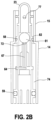
- Figures 2A to 2B show enlarged views of the exemplary embodiment of a writing instrument of the present disclosure.
- Figure 1A is a cutaway view of a writing instrument oriented in a writing orientation, i.e. oriented substantially perpendicularly or obliquely relative to the ground with a writing tip 7 oriented downward. This orientation may be similar to how a writing instrument is oriented when it is handled by a user for writing purpose.
- Figure 1B is a cutaway view of the writing instrument in a resting orientation, i.e. substantially parallel to the ground (or at angle less than 90° relative to the oblique writing orientation), such as how a writing instrument is oriented when not handled by a user engaged in writing.
- the writing instrument may be a marker, a felt pen, a highlighter, a ball point pen, a permanent or non-permanent marker or any other type of writing instrument or stylus with an extension and retraction mechanism for extending and retracting a writing tip 7 of the instrument when necessary.
- the writing tip 7 may, for example, convey ink to a writing surface when the writing instrument is ink-based.
- the writing tip 7 may be a contact point when the writing instrument is a stylus, such as, for instance, a stylus that may be used to interact with an electronic writing surface.
- the writing instrument 10 may comprise a barrel or tubular body 12 having a longitudinal axis X.
- the tubular body may be a unitary body, or may comprise multiple components.
- the barrel may have different diameters at different points along the length of the barrel. For instance, a first barrel segment 14 is shown to have a first barrel diameter and a second barrel segment 15 is shown to have a second barrel diameter. In this example, the second barrel diameter is small than the second barrel diameter.
- Figure 1A a portion of the length of the barrel has been withdrawn to show the internal mechanism involved in the present disclosure.
- the writing instrument 10 may comprise at a first forward end of the instrument a tip component 18 comprising a writing orifice 18a which is located at the distal end of the tip component 18.
- the tip component 18 may be formed as part of the barrel 12 or may be separable from the barrel 12, such as by connector elements on one or both of the barrel 12 and the tip component 18.
- the tip component 18 may have an attachable connector, such as the threading shown in the illustration, that engages with threading on the barrel 18, or with threading on another element that connects with the barrel 18.
- the writing instrument 10 may comprise, at a second opposed rearward end of the instrument, a cap 23.
- the cap 23 may be actuated by a user, e.g. by pressing the latter with a finger (e.g.
- the writing instrument 10 may further comprise in the tubular body a tank 26 for storing a writing ink used by the writing tip. As shown in figure 1B , the barrel 12 may extend longitudinally in a rearward direction so as to cover as a sheath the internal components of the writing instrument.
- the writing instrument 10 may comprise, within the barrel 12, a writing tip extension-retraction system or mechanism 32 that is configured to slide axially (along axis X) inside the barrel 12 between a first extended forward position wherein the writing tip 20 extends outside the distal writing orifice 18a ( figure 1A ) and a second retracted rearward position illustrated in figure 1B in which the writing tip 7 has been retracted inside the barrel 10 along an axial rearward direction (arrow R on figure 1B ) from the first extended forward position of figures 1A and 1B .
- a writing tip extension-retraction system or mechanism 32 that is configured to slide axially (along axis X) inside the barrel 12 between a first extended forward position wherein the writing tip 20 extends outside the distal writing orifice 18a ( figure 1A ) and a second retracted rearward position illustrated in figure 1B in which the writing tip 7 has been retracted inside the barrel 10 along an axial rearward direction (arrow R on figure 1B ) from the first extended forward position
- the writing tip extension-retraction system 32 may further comprise other internal components such as a nib 35 of which a first end forms the writing tip 7 and a nib holder 37, e. g. a sleeve surrounding the nib, which may at least partly surround the nib 35 and firmly maintain the latter inside the nib holder 37.
- the nib 35 is fixed inside the nib holder 37 and the latter is fixed to an inner tube 42, i.e. the tube containing the ink tank, e.g. through tight engagement or insertion of the second opposed end of the nib 35 into an opened first end of the inner tube 42.
- the inner tube 42 extends rearwardly and is configured to move in accordance with the writing tip extension-retraction mechanism 32 between a position that is located proximate the rear end of the barrel 12, in the first forward extended position of figure 1A , and a position located beyond the rear end of the barrel 12 in the second rearward retracted position of figure 1B .
- the writing tip extension-retraction system 32 may further comprise a biasing member 45 (e.g. a spring) that is longitudinally disposed in the instrument and has two opposite ends along its longitudinal dimension: one end, 45a, may rest against at least one fixed stop 48 that is arranged on an inner surface of the barrel 12, e.g. under the form of a peripheral inner ridge, and the opposite end 45b of biasing member 45 may press against a rear part of the inner tube 42, here on an outside shoulder 49 thereof.
- a biasing member 45 e.g. a spring
- biasing member 45 is positioned between a fixed part 48 of the barrel and the inner tube 42 so as to exert permanent rearward pulling forces on the latter (in rearward direction R) which tend to pull rearwardly the inner tube 42, and therefore the writing tip extension-retraction system 32 toward the second retracted position of figure 1B .
- the writing instrument 10 may further comprise a pneumatic system that is movable between two positions:
- the pneumatic system 52 may comprise a sealing system configured to create a pressure difference between the pneumatic system 52 and the barrel 12.
- the pneumatic system 52 may include an air valve 56 configured to be engaged with a first portion of the writing tip extension-retraction system 32, a first seal 58, and a second seal 59.
- the first seal 58 and second seal 59 may be arranged concentrically on the air valve 56 and/or inner tube 42, with the first seal 58 located closer to forward tip component 18 and the second seal 59 located closer to the cap 23.
- the pneumatic system may also comprise a movable part 61 which is configured to be subject to forwardly oriented pressure forces which press forwardly, i.e. toward the forward tip component 18 in the direction of arrow F in figure 1A when the writing instrument is in a writing orientation.
- the air valve 56 may have an air valve inlet nozzle 64 that is located on the air valve 56 between the first seal 58 and the second seal 59.
- the air valve inlet nozzle 64 may connect to a channel 67 that passes through the air valve 56 to an air valve outlet nozzle 72 such that the air valve 56 and air valve outlet nozzle 72 are in fluid communication.
- the channel 67 forms a passage that allows the transfer of air between an internal chamber 74 of the barrel 12 and an external environment.
- the cap 23 may be connected to the air valve 56 in such a way so as to form a contiguous hollow space inside and/or between the cap 23 and air valve 56.
- the channel 67 may allow the transfer of air between the internal chamber of the barrel 12 and this hollow space.
- the cap 23 may have an outlet hole 77 that allows for the transfer of air between the hollow space and the external environment.
- the moveable part 61 may be housed within the hollow space at the rearward end of the air valve 56.
- the moveable part 61 may be constricted from movement on a first end by the air valve outlet nozzle 72 and on a second end by the cap 23, which may be configured so as to prevent the moveable part 61 from falling out of the writing instrument.
- the moveable part 61 may be freely moveable along a single axis, such as the x axis.
- the moveable part is configured to be moved in the axial rearward direction (R) when the writing instrument is moved from a writing orientation as shown in figure 1A to a resting orientation such as a horizontal orientation as shown in figure 1B that is parallel to the floor or ground or to a lying surface (e.g. table etc.).
- the moveable part 61 is shown, for example, to be a sphere with a diameter that is substantially similar to the diameter of the inside of the air valve 56.
- the sphere may roll along the center axis in the forward direction, and when the orientation of the writing instrument is reversed the sphere may roll along the center axis in the rearward direction, but the sphere is substantially restricted from rolling in a non-axial direction.
- Other geometries for the moveable part 61 may be envisaged.
- the movement of the moveable part 61 within the hollow space may be governed by gravity.
- gravity For example, when the writing instrument is held in a writing orientation, i.e., when the forward direction is a collinear vector in the same direction as gravity, the moveable part 61 may be pulled in the forward direction of the hollow space to a front position, which may be the first end of the of the hollow space. Conversely, when the writing instrument is flipped such that the forward direction is a collinear vector in the opposite direction as gravity, the moveable part 61 may be pulled in the rearward direction toward a rear position, which may be the second end of the hollow space.
- the moveable part 61 may be formed from rubber, plastic, metal, a combination of these materials, or other materials that allow the described structure and weight attributes.
- the moveable part 61 When the moveable part 61 is in the front position such that the moveable part 61 is resting on the first end of the hollow space, e.g., the air valve outlet nozzle 72, the moveable part 61 may be in a blocking position, wherein the moveable part 71 blocks substantially all of the air valve outlet nozzle 72, and thus substantially prevents the passage of air between the internal chamber and the external environment, as shown in figure 2B .
- the air valve outlet nozzle 72 may be configured to be capable of maintaining a seal with the moveable part 61.
- the air valve outlet nozzle 72 may be formed from overmolded rubber, or have a flat seal with a spring, or other configurations that have been contemplated for this purpose.
- the moveable part 61 When the writing instrument is in the writing orientation of figure 1A , the moveable part 61 may be kept in the blocking position by gravity. Additionally, the moveable part 61 may move away from the blocking position depending on the inclination of the writing instrument relative to a surface and/or the gravitation force, as shown in figures 1A and 1B .
- the inner surface of the second barrel segment 15 may have grooves 78 in the internal shape of the second barrel segment 15 that run parallel to axis X, and can be better seen in figure 2A . Air that is in the barrel 12 may pass out of the barrel 12 via channels formed between the grooves 78 because the grooves 78 may be configured to prevent the second seal 59 from being completely flush with the inner face of the barrel 12.
- the grooves 78 may end in a sealing area 82, with the sealing area 82 having a surface that is flat, i.e. lacking texture, such that when the second seal 59 is in the sealing area 82, the second seal 59 may be substantially flush with the inner surface of the barrel 12 and air may be unable to pass between the second seal 59 and the inner surface of the barrel 12.
- the pneumatic system When the cap 23 is pressed by the user, the pneumatic system is actuated. This has the effect of moving the pneumatic system within the barrel in the forward direction from the second unlocked position as shown in figure 2A into the first locked position shown in Figure 2B . Air that is within the barrel 12 may pass out of the barrel 12 via the grooves in the second barrel segment 15 and/or the air valve outlet nozzle 77 until the pneumatic system reaches the locked position, placing the second seal 59 in the sealing area. This leads to a "sealing chamber," the area between the first seal 58 and the second seal 59, to be substantially enclosed so long as the air valve outlet nozzle 72 is covered.
- the pneumatic system When the pneumatic system is in the locking position and the moveable part 61 is covering the air valve outlet nozzle 72, such as when the moveable part 61 is submitted to the forwardly-oriented forces due to the weight of the moveable part 61 (due to gravity attraction which attracts the moveable part 61 downwardly) in the writing orientation, such as when the writing instrument is oriented as in figure 1A (the writing instrument 10 is placed in an inclined writing orientation relative to the floor or the lying surface or support, e.g. a table, on which a user intends to use the instrument), the seal on the sealing chamber is maintained, and the pressure difference, which may take the form of a suction force, between the pneumatic system and the barrel 12 resists the biasing force of the biasing member 45.
- the pneumatic system is configured to cooperate with the barrel to arrange the sealing chamber within the barrel so that the sealing chamber is substantially airtight.
- the writing tip extension retraction system 32 is maintained in the locked position of figure 1A and figure 2B when the writing instrument, and thus the pneumatic system, is in the writing orientation (first extended forward position of the writing tip extension-retraction system 32 where the writing tip 7 extends outside the barrel).
- the moveable part 61 When the pneumatic system is in the locked position and the writing instrument 10 is moved from the writing orientation to the resting orientation, such as when the writing instrument is oriented as in figure 1B (or an orientation not represented on the drawings with the writing tip oriented upwardly, i.e. in a direction away from the floor), the moveable part 61 is naturally moved rearwardly within the housing, sliding axially therein due to its weight. The rearward displacement of the moveable part 61 uncovers the air valve outlet nozzle 72, allowing once again the free passage of air between the sealing chamber and the external environment, via the outlet hole 77, which equalizes the pressure difference.
- the pneumatic system can no longer withstand on its own the rearwardly-oriented biasing forces exerted by biasing member 45. This causes the pneumatic system to move in direction R as shown in figure 1B , thus also causing the writing tip extension-retraction system to move rearwardly to the second retracted unlocked position of figure 1B and figure 2A (the locking system is thus caused to move from the locked position to the unlocked position).
- the writing tip extension-retraction system 32 is thus automatically released without any specific action from a user (except the change in orientation of the writing instrument from a writing orientation to a resting orientation such as a horizontal orientation or even to an orientation where the writing tip is facing upwardly and the cap 23 downwardly) and can slide rearwardly inside the barrel under the action of biasing member 45, which is no longer compensated for, to occupy the second retracted unlocked position of figure 1B . Therefore the mere change in orientation of the writing instrument as described above makes it possible to automatically unlock the writing tip extension-retraction system and cause the latter to move to a second retracted rearward position wherein the writing tip is retracted inside the barrel ( figure 1B ).
- two or more of the inner tube 42, air valve 56, first seal 58, and second seal 59 may be formed from a single component.
- the air valve 56 and inner tube 42 may be molded as one part during manufacturing such that the air valve 56 and inner tube 42 cannot be separated.
- the first seal 58 and/or the second seal 59 such that the seals may be molded as part of their associated components during manufacturing, e.g., overmolding may be employed to combine the first seal 58 with the inner tube 48 and/or the second seal 59 with the air valve 56. Any combination of the above configurations may be contemplated.
Landscapes
- Mechanical Pencils And Projecting And Retracting Systems Therefor, And Multi-System Writing Instruments (AREA)
Abstract
A writing instrument (10) that includes a barrel (12), a writing tip (7), a writing tip extension-retraction system (32) configured to slide axially inside the barrel (12) between a first extended forward position wherein the writing tip (7) extends outside the barrel (12) and a second retracted rearward position wherein the writing tip (7) is retracted inside the barrel (12) from the first extended forward position along an axial rearward direction (R), a pneumatic system movable between a locked position wherein the pneumatic system is engaged with the writing tip extension retraction system (32) in the first extended forward position so as to lock the writing tip extension retraction system in this position and an unlocked position wherein the pneumatic system is disengaged from the writing tip extension-retraction system (32).
Description
- The present disclosure relates to the field of writing devices. More specifically, the present disclosure relates to writing devices with a writing tip that can be extended and retracted.
- Writing instruments comprising a barrel and a writing tip that can be extended outside the barrel for writing purpose when a user actuates a writing tip extension-retraction system inside the barrel and retracted inside the barrel when the user no longer needs to use the writing instrument are largely known.
- Further, prior art systems which automatically retract the writing tip of a writing instrument inside the barrel are also known, such as systems described in patent documents
US 10,532,601 B2 US 2004/228671 A1 andUS 8,100,598 B2 . - However, these systems need actuation by the user which may forget to retract back the writing tip after using the writing instrument thereby e.g. drying writing tip for those writing implements using ink or keeping the writing tip more vulnerable e.g. if the writing implement falls down.
- The present disclosure aims to address one or more problems in the prior art.
- In a first aspect, the present disclosure relates to a writing instrument. The writing instrument comprises a barrel having a longitudinal axis, a writing tip, and a writing tip extension-retraction system configured to slide axially inside the barrel between a first extended forward position wherein the writing tip extends outside the barrel and a second retracted rearward position wherein the writing tip is retracted inside the barrel from the first extended forward position along an axial rearward direction. The writing instrument further comprises a pneumatic system movable between a locked position wherein the pneumatic system is engaged with the writing tip extension retraction system in the first extended forward position so as to lock the writing tip extension retraction system in this position and an unlocked position wherein the pneumatic system is disengaged from the writing tip extension-retraction system. The pneumatic system is configured to create a pressure difference between the pneumatic system and the barrel when the writing instrument is in a writing orientation and the pneumatic system is moved into the locked position, and configured to equalize the pressure difference when the pneumatic system is moved into a resting orientation.
- According to the first aspect, the writing tip extension-retraction system may be easily and reliably caused to move to a second retracted rearward position by merely moving (through a user) the writing instrument to a horizontal orientation or an orientation with the writing tip oriented upwardly without carrying out any other action such as exerting an effort on an actuation member, e.g. pulling, pressing etc. The specific structure of the pneumatic system may minimize the moving parts necessary for operation of the device, thus decreasing the chance of dysfunction or wear within the device. This may also make the device cheaper and easier to manufacture.
- A horizontal orientation or an orientation with the writing tip oriented upwardly or facing up may be considered as a resting orientation; i.e. an orientation in which the writing instrument is no longer configured for writing purpose. In the present disclosure, the horizontal orientation or upward orientation is defined relative to the floor or ground or a lying surface or support, e.g. a table, on which the writing instrument can be laid down in a resting orientation. The upward orientation of the writing tip more particularly defines an orientation that is opposed to the floor/ground (or a lying surface or support) where the writing tip faces up with respect to the floor/ground. The writing tip of the writing instrument would, in contrast, be oriented downwardly if it were facing the floor/ground or a lying surface or support, in particular when contemplating a writing task with the writing instrument. In the present disclosure the retraction movement may be automatically achieved through reorienting the writing instrument as described above, in particular through lifting the writing tip upwardly. More particularly, the natural movement of the user after writing is to lift the writing tip from the writing surface and orient the writing instrument either horizontally or even with the writing tip facing up. The gesture of the user may cause a weight to move relative to the writing instrument and, notably the pneumatic system thereof, thereby causing unlocking of the latter thanks to the removal of the pressure difference.
- In embodiments, the pneumatic system may be configured to maintain the writing extension-retraction system in the first extended forward position when the writing instrument is in a writing orientation.
- In embodiments, the pneumatic system may be configured to cooperate with the barrel to arrange an internal chamber within the barrel that is airtight when the pneumatic system is actuated into the locked position.
- In embodiments, the pneumatic system may comprise a sealing system configured to create the pressure difference and a moveable part configured to be subjected to forwardly oriented pressure forces.
- In embodiments, the sealing system may be configured to push air out of the internal chamber when the sealing system moves into a forward position.
- In embodiments, the sealing system may comprise an air valve, a first seal, and a second seal, wherein the first seal and the second seal may be configured to engage with an inner face of the barrel when the sealing system is in a first forward position.
- In embodiments, the first seal may be disposed on an outer face of the writing tip extension-retraction system and the second seal may be disposed on an outer face of the air valve.
- In embodiments, the sealing system may comprise a first air outlet and a second air outlet, wherein the first air outlet may be disposed on the air valve between the first seal and the second seal, and the second air outlet may be disposed on a rearward face of the air valve, wherein the first air outlet and the second air outlet may be in fluid communication.
- In embodiments, the moveable part may be moveable between a front position and a rear position, wherein the moveable part moves to the front position when the moveable part is submitted to forwardly-oriented forces.
- In embodiments, the moveable part may be configured to seal the second air outlet against air passage when the moveable part is in the front position and the sealing system is in the locked position.
- In embodiments, the moveable part may be a sphere.
- In embodiments, the pneumatic system may be configured to unlock the writing tip extension-retraction system, allowing the writing tip extension-retraction system to move to the second retracted rearward position, when the writing tip extension-retraction system is in the first extended forward position and the moveable part moves in the rearward direction.
- In embodiments, the sealing system may comprise a cap that is configured to be pressed in a forward direction to actuate the pneumatic system.
- In embodiments, the writing tip extension-retraction system may further comprise a biasing member configured to bias the writing tip extension retraction system in the rearward direction.
- In embodiments, the biasing member may be a spring.
-
Figures 1A to 1B show a first exemplary embodiment of a writing instrument of the present disclosure. -
Figures 2A to 2B show enlarged views of the exemplary embodiment of a writing instrument of the present disclosure. - Hereinafter, a detailed description will be given of the present disclosure. The terms or words used in the description and the aspects of the present disclosure are not to be construed limiting as only having common-language or dictionary meanings and should, unless specifically defined otherwise in the following description, be interpreted as having their ordinary technical meaning as established in the relevant technical field. The detailed description will refer to specific embodiments to better illustrate the present disclosure, however, it should be understood that the presented disclosure is not limited to these specific embodiments.
- In the present disclosure the term "gravity" naturally refers to the newtonian gravitational acceleration created by the earth and the term "gravity direction" refers to the direction of the acceleration which is oriented downwardly with respect to the location where the writing instrument is located.
- In a first exemplary embodiment, the present disclosure relates to a writing instrument as shown in
figures 1A and 1B , of which the description follows.Figure 1A is a cutaway view of a writing instrument oriented in a writing orientation, i.e. oriented substantially perpendicularly or obliquely relative to the ground with awriting tip 7 oriented downward. This orientation may be similar to how a writing instrument is oriented when it is handled by a user for writing purpose.Figure 1B is a cutaway view of the writing instrument in a resting orientation, i.e. substantially parallel to the ground (or at angle less than 90° relative to the oblique writing orientation), such as how a writing instrument is oriented when not handled by a user engaged in writing. - The writing instrument may be a marker, a felt pen, a highlighter, a ball point pen, a permanent or non-permanent marker or any other type of writing instrument or stylus with an extension and retraction mechanism for extending and retracting a
writing tip 7 of the instrument when necessary. Thewriting tip 7 may, for example, convey ink to a writing surface when the writing instrument is ink-based. Alternatively, or additionally, thewriting tip 7 may be a contact point when the writing instrument is a stylus, such as, for instance, a stylus that may be used to interact with an electronic writing surface. - The writing instrument 10 may comprise a barrel or
tubular body 12 having a longitudinal axis X. The tubular body may be a unitary body, or may comprise multiple components. The barrel may have different diameters at different points along the length of the barrel. For instance, afirst barrel segment 14 is shown to have a first barrel diameter and asecond barrel segment 15 is shown to have a second barrel diameter. In this example, the second barrel diameter is small than the second barrel diameter. InFigure 1A , a portion of the length of the barrel has been withdrawn to show the internal mechanism involved in the present disclosure. - The writing instrument 10 may comprise at a first forward end of the instrument a
tip component 18 comprising awriting orifice 18a which is located at the distal end of thetip component 18. Thetip component 18 may be formed as part of thebarrel 12 or may be separable from thebarrel 12, such as by connector elements on one or both of thebarrel 12 and thetip component 18. For instance, thetip component 18 may have an attachable connector, such as the threading shown in the illustration, that engages with threading on thebarrel 18, or with threading on another element that connects with thebarrel 18. The writing instrument 10 may comprise, at a second opposed rearward end of the instrument, acap 23. Thecap 23 may be actuated by a user, e.g. by pressing the latter with a finger (e.g. the thumb) forwardly along the axis X so as to cause extension of thewriting tip 7 of the instrument through thewriting orifice 18a in a known manner. To be noted that other actuating members may be used for causing writingtip 7 extension. The writing instrument 10 may further comprise in the tubular body atank 26 for storing a writing ink used by the writing tip. As shown infigure 1B , thebarrel 12 may extend longitudinally in a rearward direction so as to cover as a sheath the internal components of the writing instrument. - The writing instrument 10 may comprise, within the
barrel 12, a writing tip extension-retraction system ormechanism 32 that is configured to slide axially (along axis X) inside thebarrel 12 between a first extended forward position wherein the writing tip 20 extends outside thedistal writing orifice 18a (figure 1A ) and a second retracted rearward position illustrated infigure 1B in which thewriting tip 7 has been retracted inside the barrel 10 along an axial rearward direction (arrow R onfigure 1B ) from the first extended forward position offigures 1A and 1B . - The writing tip extension-
retraction system 32 may further comprise other internal components such as anib 35 of which a first end forms thewriting tip 7 and anib holder 37, e. g. a sleeve surrounding the nib, which may at least partly surround thenib 35 and firmly maintain the latter inside thenib holder 37. Thenib 35 is fixed inside thenib holder 37 and the latter is fixed to aninner tube 42, i.e. the tube containing the ink tank, e.g. through tight engagement or insertion of the second opposed end of thenib 35 into an opened first end of theinner tube 42. Theinner tube 42 extends rearwardly and is configured to move in accordance with the writing tip extension-retraction mechanism 32 between a position that is located proximate the rear end of thebarrel 12, in the first forward extended position offigure 1A , and a position located beyond the rear end of thebarrel 12 in the second rearward retracted position offigure 1B . - The writing tip extension-
retraction system 32 may further comprise a biasing member 45 (e.g. a spring) that is longitudinally disposed in the instrument and has two opposite ends along its longitudinal dimension: one end, 45a, may rest against at least onefixed stop 48 that is arranged on an inner surface of thebarrel 12, e.g. under the form of a peripheral inner ridge, and theopposite end 45b of biasingmember 45 may press against a rear part of theinner tube 42, here on anoutside shoulder 49 thereof. Thus the biasingmember 45 is positioned between afixed part 48 of the barrel and theinner tube 42 so as to exert permanent rearward pulling forces on the latter (in rearward direction R) which tend to pull rearwardly theinner tube 42, and therefore the writing tip extension-retraction system 32 toward the second retracted position offigure 1B . - The writing instrument 10 may further comprise a pneumatic system that is movable between two positions:
- -a first locked position wherein the pneumatic system engages with the writing tip
extension retraction system 32 in the first extended forward position offigure 1A so as to lock the latter in this position and withstand the biasing forces exerted in the rearward direction by the biasingmember 45; - -and a second unlocked position wherein the pneumatic system is disengaged from the writing tip extension-
retraction system 32, and does therefore no longer counter the biasing forces, thereby enabling rearward sliding of thesystem 32 as shown infigure 1B which reaches the second retracted rearward position. - More particularly, as shown in the enlarged drawings of
figures 2A and2B , thepneumatic system 52 may comprise a sealing system configured to create a pressure difference between thepneumatic system 52 and thebarrel 12. Thepneumatic system 52 may include anair valve 56 configured to be engaged with a first portion of the writing tip extension-retraction system 32, afirst seal 58, and asecond seal 59. Thefirst seal 58 andsecond seal 59 may be arranged concentrically on theair valve 56 and/orinner tube 42, with thefirst seal 58 located closer toforward tip component 18 and thesecond seal 59 located closer to thecap 23. For example, thefirst seal 58 is shown to be disposed on theinner tube 42, and thesecond seal 59 is shown to be disposed on theair valve 56, although other configurations are conceived. The pneumatic system may also comprise amovable part 61 which is configured to be subject to forwardly oriented pressure forces which press forwardly, i.e. toward theforward tip component 18 in the direction of arrow F infigure 1A when the writing instrument is in a writing orientation. - The
air valve 56 may have an airvalve inlet nozzle 64 that is located on theair valve 56 between thefirst seal 58 and thesecond seal 59. The airvalve inlet nozzle 64 may connect to achannel 67 that passes through theair valve 56 to an airvalve outlet nozzle 72 such that theair valve 56 and airvalve outlet nozzle 72 are in fluid communication. Thechannel 67 forms a passage that allows the transfer of air between aninternal chamber 74 of thebarrel 12 and an external environment. Additionally, or alternatively, thecap 23 may be connected to theair valve 56 in such a way so as to form a contiguous hollow space inside and/or between thecap 23 andair valve 56. Thus, thechannel 67 may allow the transfer of air between the internal chamber of thebarrel 12 and this hollow space. Thecap 23 may have anoutlet hole 77 that allows for the transfer of air between the hollow space and the external environment. - The
moveable part 61 may be housed within the hollow space at the rearward end of theair valve 56. Themoveable part 61 may be constricted from movement on a first end by the airvalve outlet nozzle 72 and on a second end by thecap 23, which may be configured so as to prevent themoveable part 61 from falling out of the writing instrument. Themoveable part 61 may be freely moveable along a single axis, such as the x axis. In the illustration, the moveable part is configured to be moved in the axial rearward direction (R) when the writing instrument is moved from a writing orientation as shown infigure 1A to a resting orientation such as a horizontal orientation as shown infigure 1B that is parallel to the floor or ground or to a lying surface (e.g. table etc.). Themoveable part 61 is shown, for example, to be a sphere with a diameter that is substantially similar to the diameter of the inside of theair valve 56. Thus, when the writing instrument is in a downward orientation, the sphere may roll along the center axis in the forward direction, and when the orientation of the writing instrument is reversed the sphere may roll along the center axis in the rearward direction, but the sphere is substantially restricted from rolling in a non-axial direction. Other geometries for themoveable part 61 may be envisaged. - The movement of the
moveable part 61 within the hollow space may be governed by gravity. For example, when the writing instrument is held in a writing orientation, i.e., when the forward direction is a collinear vector in the same direction as gravity, themoveable part 61 may be pulled in the forward direction of the hollow space to a front position, which may be the first end of the of the hollow space. Conversely, when the writing instrument is flipped such that the forward direction is a collinear vector in the opposite direction as gravity, themoveable part 61 may be pulled in the rearward direction toward a rear position, which may be the second end of the hollow space. Themoveable part 61 may be formed from rubber, plastic, metal, a combination of these materials, or other materials that allow the described structure and weight attributes. - When the
moveable part 61 is in the front position such that themoveable part 61 is resting on the first end of the hollow space, e.g., the airvalve outlet nozzle 72, themoveable part 61 may be in a blocking position, wherein the moveable part 71 blocks substantially all of the airvalve outlet nozzle 72, and thus substantially prevents the passage of air between the internal chamber and the external environment, as shown infigure 2B . The airvalve outlet nozzle 72 may be configured to be capable of maintaining a seal with themoveable part 61. For example, the airvalve outlet nozzle 72 may be formed from overmolded rubber, or have a flat seal with a spring, or other configurations that have been contemplated for this purpose. When the writing instrument is in the writing orientation offigure 1A , themoveable part 61 may be kept in the blocking position by gravity. Additionally, themoveable part 61 may move away from the blocking position depending on the inclination of the writing instrument relative to a surface and/or the gravitation force, as shown infigures 1A and 1B . - The inner surface of the
second barrel segment 15 may havegrooves 78 in the internal shape of thesecond barrel segment 15 that run parallel to axis X, and can be better seen infigure 2A . Air that is in thebarrel 12 may pass out of thebarrel 12 via channels formed between thegrooves 78 because thegrooves 78 may be configured to prevent thesecond seal 59 from being completely flush with the inner face of thebarrel 12. Thegrooves 78 may end in a sealingarea 82, with the sealingarea 82 having a surface that is flat, i.e. lacking texture, such that when thesecond seal 59 is in the sealingarea 82, thesecond seal 59 may be substantially flush with the inner surface of thebarrel 12 and air may be unable to pass between thesecond seal 59 and the inner surface of thebarrel 12. - When the
cap 23 is pressed by the user, the pneumatic system is actuated. This has the effect of moving the pneumatic system within the barrel in the forward direction from the second unlocked position as shown infigure 2A into the first locked position shown inFigure 2B . Air that is within thebarrel 12 may pass out of thebarrel 12 via the grooves in thesecond barrel segment 15 and/or the airvalve outlet nozzle 77 until the pneumatic system reaches the locked position, placing thesecond seal 59 in the sealing area. This leads to a "sealing chamber," the area between thefirst seal 58 and thesecond seal 59, to be substantially enclosed so long as the airvalve outlet nozzle 72 is covered. - When the pneumatic system is in the locking position and the
moveable part 61 is covering the airvalve outlet nozzle 72, such as when themoveable part 61 is submitted to the forwardly-oriented forces due to the weight of the moveable part 61 (due to gravity attraction which attracts themoveable part 61 downwardly) in the writing orientation, such as when the writing instrument is oriented as infigure 1A (the writing instrument 10 is placed in an inclined writing orientation relative to the floor or the lying surface or support, e.g. a table, on which a user intends to use the instrument), the seal on the sealing chamber is maintained, and the pressure difference, which may take the form of a suction force, between the pneumatic system and thebarrel 12 resists the biasing force of the biasingmember 45. As such, the pneumatic system is configured to cooperate with the barrel to arrange the sealing chamber within the barrel so that the sealing chamber is substantially airtight. - Thus, the writing tip
extension retraction system 32 is maintained in the locked position offigure 1A andfigure 2B when the writing instrument, and thus the pneumatic system, is in the writing orientation (first extended forward position of the writing tip extension-retraction system 32 where thewriting tip 7 extends outside the barrel). - When the pneumatic system is in the locked position and the writing instrument 10 is moved from the writing orientation to the resting orientation, such as when the writing instrument is oriented as in
figure 1B (or an orientation not represented on the drawings with the writing tip oriented upwardly, i.e. in a direction away from the floor), themoveable part 61 is naturally moved rearwardly within the housing, sliding axially therein due to its weight. The rearward displacement of themoveable part 61 uncovers the airvalve outlet nozzle 72, allowing once again the free passage of air between the sealing chamber and the external environment, via theoutlet hole 77, which equalizes the pressure difference. Owing to the absence of the suction force of the sealing chamber when the sealing chamber has a fluid connection with the external environment, the pneumatic system can no longer withstand on its own the rearwardly-oriented biasing forces exerted by biasingmember 45. This causes the pneumatic system to move in direction R as shown infigure 1B , thus also causing the writing tip extension-retraction system to move rearwardly to the second retracted unlocked position offigure 1B andfigure 2A (the locking system is thus caused to move from the locked position to the unlocked position). - The writing tip extension-
retraction system 32 is thus automatically released without any specific action from a user (except the change in orientation of the writing instrument from a writing orientation to a resting orientation such as a horizontal orientation or even to an orientation where the writing tip is facing upwardly and thecap 23 downwardly) and can slide rearwardly inside the barrel under the action of biasingmember 45, which is no longer compensated for, to occupy the second retracted unlocked position offigure 1B . Therefore the mere change in orientation of the writing instrument as described above makes it possible to automatically unlock the writing tip extension-retraction system and cause the latter to move to a second retracted rearward position wherein the writing tip is retracted inside the barrel (figure 1B ). - In embodiments, two or more of the
inner tube 42,air valve 56,first seal 58, andsecond seal 59 may be formed from a single component. For instance, theair valve 56 andinner tube 42 may be molded as one part during manufacturing such that theair valve 56 andinner tube 42 cannot be separated. The same may be true of thefirst seal 58 and/or thesecond seal 59, such that the seals may be molded as part of their associated components during manufacturing, e.g., overmolding may be employed to combine thefirst seal 58 with theinner tube 48 and/or thesecond seal 59 with theair valve 56. Any combination of the above configurations may be contemplated. - Although the embodiments of the present disclosure have been disclosed for illustrative purposes, those skilled in the art will appreciate that various modifications and alterations are possible, without departing from the spirit of the present disclosure. It is also to be understood that such modifications and alterations are incorporated in the scope of the present disclosure and the accompanying claims.
Claims (15)
- A writing instrument (10) comprising:- a barrel (12),- a writing tip (7),- a writing tip extension-retraction system (32) configured to slide axially inside the barrel (12) between a first extended forward position wherein the writing tip (7) extends outside the barrel (12) and a second retracted rearward position wherein the writing tip (7) is retracted inside the barrel (12) from the first extended forward position along an axial rearward direction (R), and- a pneumatic system movable between a locked position wherein the pneumatic system is engaged with the writing tip extension retraction system (32) in the first extended forward position so as to lock the writing tip extension retraction system (32) in this position, and an unlocked position wherein the pneumatic system is disengaged from the writing tip extension-retraction system (32),wherein the pneumatic system is configured to create a pressure difference between the pneumatic system and the barrel (12) when the writing instrument (10) is in a writing orientation and the pneumatic system is moved into the locked position, and configured to equalize the pressure difference when the pneumatic system is in the locked position and the writing instrument (10) is moved into a resting orientation.
- The writing instrument (10) of claim 1, wherein the pneumatic system is configured to maintain the writing extension-retraction system (32) in the first extended forward position when the pneumatic system is in the locked position and the writing instrument (10) is in a writing orientation.
- The writing instrument (10) of any of claims 1 or 2, wherein the pneumatic system is configured to cooperate with the barrel (12) to arrange an internal chamber within the barrel (12) that is airtight when the pneumatic system is actuated into the locked position.
- The writing instrument of any of claims 1 to 3, wherein the pneumatic system comprises a sealing system configured to create the pressure difference and a moveable part (61) configured to be subjected to forwardly oriented pressure forces.
- The writing instrument (10) of claim 4, wherein the sealing system is configured to push air out of the internal chamber when the sealing system moves into a forward position.
- The writing instrument (10) of any of claims claim 4 to 5, wherein the sealing system comprises an air valve (56), a first seal (58), and a second seal (59), wherein the first seal (58) and the second seal (59) are configured to engage with an inner face of the barrel (12) when the sealing system is in a first forward position.
- The writing instrument (10) of claim 6, wherein the first seal (58) is disposed on an outer face of the writing tip extension-retraction system (32) and the second seal (59) is disposed on an outer face of the air valve (56).
- The writing instrument (10) of any of claims 4 to 7, wherein the sealing system comprises a first air outlet (64) and a second air outlet (72), wherein the first air outlet (64) is disposed on the air valve (56) between the first seal (58) and the second seal (59), and the second air outlet (72) is disposed on a rearward face of the air valve (56), wherein the first air outlet (64) and the second air outlet (72) are in fluid communication.
- The writing instrument (10) of any of claims 4 to 8, wherein the moveable part (61) is moveable between a front position and a rear position, wherein the moveable part (61) moves to the front position when the moveable part (61) is submitted to forwardly-oriented pressure forces.
- The writing instrument (10) of claim 9, wherein the moveable part (61) is configured to seal the second air outlet (72) against air passage when the moveable part (61) is in the front position and the sealing system is in the locked position.
- The writing instrument (10) of any of claims 4 to 10, wherein the moveable part (61) is a sphere.
- The writing instrument (10) of any of claims 4 to 11, wherein the pneumatic system is configured to unlock the writing tip extension-retraction system (32), allowing the writing tip extension-retraction system (32) to move to the second retracted rearward position, when the writing tip extension-retraction system (32) is in the first extended forward position and the moveable part (61) moves in the rearward direction (R).
- The writing instrument (10) of any of claims 4 to 12 wherein the sealing system comprises a cap (23) that is configured to be pressed in a forward direction (F) to actuate the pneumatic system.
- The writing instrument (10) of any one of the preceding claims, wherein the writing tip extension-retraction system (32) further comprises a biasing member (45) configured to bias the writing tip extension retraction system (32) in the rearward direction (R).
- The writing instrument of claim 14, wherein the biasing member (45) is a spring.
Priority Applications (2)
| Application Number | Priority Date | Filing Date | Title |
|---|---|---|---|
| EP21306885.1A EP4201692A1 (en) | 2021-12-21 | 2021-12-21 | Writing instruments |
| PCT/EP2022/086382 WO2023117770A1 (en) | 2021-12-21 | 2022-12-16 | Writing instruments |
Applications Claiming Priority (1)
| Application Number | Priority Date | Filing Date | Title |
|---|---|---|---|
| EP21306885.1A EP4201692A1 (en) | 2021-12-21 | 2021-12-21 | Writing instruments |
Publications (1)
| Publication Number | Publication Date |
|---|---|
| EP4201692A1 true EP4201692A1 (en) | 2023-06-28 |
Family
ID=79317104
Family Applications (1)
| Application Number | Title | Priority Date | Filing Date |
|---|---|---|---|
| EP21306885.1A Withdrawn EP4201692A1 (en) | 2021-12-21 | 2021-12-21 | Writing instruments |
Country Status (2)
| Country | Link |
|---|---|
| EP (1) | EP4201692A1 (en) |
| WO (1) | WO2023117770A1 (en) |
Families Citing this family (1)
| Publication number | Priority date | Publication date | Assignee | Title |
|---|---|---|---|---|
| CN119821023A (en) * | 2025-01-21 | 2025-04-15 | 温州市爱好笔业有限公司 | Automatic retractable pen |
Citations (6)
| Publication number | Priority date | Publication date | Assignee | Title |
|---|---|---|---|---|
| US20040228671A1 (en) | 2003-05-17 | 2004-11-18 | Sunatori Go Simon | Auto-retractable pen mechanism with a cushion effect |
| EP1880868A1 (en) * | 2006-07-18 | 2008-01-23 | Tombow Pencil Co., Ltd. | Pressurized pen |
| JP2009226674A (en) * | 2008-03-21 | 2009-10-08 | Tombow Pencil Co Ltd | Ballpoint pen |
| EP2364861A1 (en) * | 2008-11-27 | 2011-09-14 | Kotobuki & Co., Ltd | Liquid supply device |
| US8100598B2 (en) | 2008-01-01 | 2012-01-24 | Thomas Killion | Two-piece magnetically actuated pen |
| US10532601B2 (en) | 2016-01-08 | 2020-01-14 | Scribe Technical Consulting Llc | Writing instrument with magnetic features and quick refill capability |
-
2021
- 2021-12-21 EP EP21306885.1A patent/EP4201692A1/en not_active Withdrawn
-
2022
- 2022-12-16 WO PCT/EP2022/086382 patent/WO2023117770A1/en not_active Ceased
Patent Citations (6)
| Publication number | Priority date | Publication date | Assignee | Title |
|---|---|---|---|---|
| US20040228671A1 (en) | 2003-05-17 | 2004-11-18 | Sunatori Go Simon | Auto-retractable pen mechanism with a cushion effect |
| EP1880868A1 (en) * | 2006-07-18 | 2008-01-23 | Tombow Pencil Co., Ltd. | Pressurized pen |
| US8100598B2 (en) | 2008-01-01 | 2012-01-24 | Thomas Killion | Two-piece magnetically actuated pen |
| JP2009226674A (en) * | 2008-03-21 | 2009-10-08 | Tombow Pencil Co Ltd | Ballpoint pen |
| EP2364861A1 (en) * | 2008-11-27 | 2011-09-14 | Kotobuki & Co., Ltd | Liquid supply device |
| US10532601B2 (en) | 2016-01-08 | 2020-01-14 | Scribe Technical Consulting Llc | Writing instrument with magnetic features and quick refill capability |
Also Published As
| Publication number | Publication date |
|---|---|
| WO2023117770A1 (en) | 2023-06-29 |
Similar Documents
| Publication | Publication Date | Title |
|---|---|---|
| US7220073B2 (en) | Slide-type writing instrument with a dry prevention unit | |
| JP4907723B2 (en) | Two-material valve, a marker incorporating the valve and having a retractable tip, and a method for producing the valve | |
| CN101500821B (en) | Slide type writing tool preventing dryness | |
| US9340060B2 (en) | Slide type writing tool having device for preventing dryness | |
| CN102414030A (en) | Writing instrument with simultaneously retractable ends | |
| WO2023117770A1 (en) | Writing instruments | |
| US6923588B1 (en) | Retractile mechanism for refill of writing instrument | |
| KR102462876B1 (en) | Writing utensil with retract piece | |
| US2580753A (en) | Ball point fountain pen | |
| US7452147B2 (en) | Writing instrument with a lateral button | |
| JP2017209863A (en) | Ink suction device | |
| US8599143B1 (en) | Switch configuration for detecting writing pressure in a writing device | |
| CN108528096B (en) | Writing instrument with self-sealing structure | |
| EP4201690A1 (en) | Writing instruments | |
| JP6881748B2 (en) | Knock-type writing tool with malfunction prevention function | |
| EP4159468A1 (en) | Writing instruments | |
| EP4159467A1 (en) | Writing instruments | |
| CN100506566C (en) | Pressurized pen | |
| JP4435724B2 (en) | Sliding multi-core writing instrument | |
| JP5210353B2 (en) | Telescopic mechanical pen | |
| JP5279297B2 (en) | Sliding composite writing instrument | |
| JPH04221700A (en) | Knock type writing utensil | |
| CN102712208A (en) | Writing instrument having a grip piece | |
| JP5279535B2 (en) | Sliding composite writing instrument | |
| EP3357707A1 (en) | Writing instrument having automatic sealing structure |
Legal Events
| Date | Code | Title | Description |
|---|---|---|---|
| PUAI | Public reference made under article 153(3) epc to a published international application that has entered the european phase |
Free format text: ORIGINAL CODE: 0009012 |
|
| STAA | Information on the status of an ep patent application or granted ep patent |
Free format text: STATUS: THE APPLICATION HAS BEEN PUBLISHED |
|
| AK | Designated contracting states |
Kind code of ref document: A1 Designated state(s): AL AT BE BG CH CY CZ DE DK EE ES FI FR GB GR HR HU IE IS IT LI LT LU LV MC MK MT NL NO PL PT RO RS SE SI SK SM TR |
|
| STAA | Information on the status of an ep patent application or granted ep patent |
Free format text: STATUS: THE APPLICATION IS DEEMED TO BE WITHDRAWN |
|
| 18D | Application deemed to be withdrawn |
Effective date: 20240103 |