EP4201605A1 - Current limiting device, robot system, and current limiting method - Google Patents
Current limiting device, robot system, and current limiting method Download PDFInfo
- Publication number
- EP4201605A1 EP4201605A1 EP21861417.0A EP21861417A EP4201605A1 EP 4201605 A1 EP4201605 A1 EP 4201605A1 EP 21861417 A EP21861417 A EP 21861417A EP 4201605 A1 EP4201605 A1 EP 4201605A1
- Authority
- EP
- European Patent Office
- Prior art keywords
- drive
- motor
- limit value
- speed
- current
- Prior art date
- Legal status (The legal status is an assumption and is not a legal conclusion. Google has not performed a legal analysis and makes no representation as to the accuracy of the status listed.)
- Pending
Links
Images




Classifications
-
- B—PERFORMING OPERATIONS; TRANSPORTING
- B25—HAND TOOLS; PORTABLE POWER-DRIVEN TOOLS; MANIPULATORS
- B25J—MANIPULATORS; CHAMBERS PROVIDED WITH MANIPULATION DEVICES
- B25J9/00—Program-controlled manipulators
- B25J9/16—Program controls
- B25J9/1628—Program controls characterised by the control loop
- B25J9/1633—Program controls characterised by the control loop compliant, force, torque control, e.g. combined with position control
-
- B—PERFORMING OPERATIONS; TRANSPORTING
- B25—HAND TOOLS; PORTABLE POWER-DRIVEN TOOLS; MANIPULATORS
- B25J—MANIPULATORS; CHAMBERS PROVIDED WITH MANIPULATION DEVICES
- B25J9/00—Program-controlled manipulators
- B25J9/10—Program-controlled manipulators characterised by positioning means for manipulator elements
- B25J9/12—Program-controlled manipulators characterised by positioning means for manipulator elements electric
-
- B—PERFORMING OPERATIONS; TRANSPORTING
- B25—HAND TOOLS; PORTABLE POWER-DRIVEN TOOLS; MANIPULATORS
- B25J—MANIPULATORS; CHAMBERS PROVIDED WITH MANIPULATION DEVICES
- B25J19/00—Accessories fitted to manipulators, e.g. for monitoring, for viewing; Safety devices combined with or specially adapted for use in connection with manipulators
- B25J19/06—Safety devices
-
- B—PERFORMING OPERATIONS; TRANSPORTING
- B25—HAND TOOLS; PORTABLE POWER-DRIVEN TOOLS; MANIPULATORS
- B25J—MANIPULATORS; CHAMBERS PROVIDED WITH MANIPULATION DEVICES
- B25J9/00—Program-controlled manipulators
- B25J9/10—Program-controlled manipulators characterised by positioning means for manipulator elements
- B25J9/12—Program-controlled manipulators characterised by positioning means for manipulator elements electric
- B25J9/126—Rotary actuators
-
- B—PERFORMING OPERATIONS; TRANSPORTING
- B25—HAND TOOLS; PORTABLE POWER-DRIVEN TOOLS; MANIPULATORS
- B25J—MANIPULATORS; CHAMBERS PROVIDED WITH MANIPULATION DEVICES
- B25J9/00—Program-controlled manipulators
- B25J9/16—Program controls
- B25J9/1628—Program controls characterised by the control loop
- B25J9/1651—Program controls characterised by the control loop acceleration, rate control
-
- B—PERFORMING OPERATIONS; TRANSPORTING
- B25—HAND TOOLS; PORTABLE POWER-DRIVEN TOOLS; MANIPULATORS
- B25J—MANIPULATORS; CHAMBERS PROVIDED WITH MANIPULATION DEVICES
- B25J9/00—Program-controlled manipulators
- B25J9/16—Program controls
- B25J9/1674—Program controls characterised by safety, monitoring, diagnostic
-
- H—ELECTRICITY
- H02—GENERATION; CONVERSION OR DISTRIBUTION OF ELECTRIC POWER
- H02P—CONTROL OR REGULATION OF ELECTRIC MOTORS, ELECTRIC GENERATORS OR DYNAMO-ELECTRIC CONVERTERS; CONTROLLING TRANSFORMERS, REACTORS OR CHOKE COILS
- H02P29/00—Arrangements for regulating or controlling electric motors, appropriate for both AC and DC motors
- H02P29/40—Regulating or controlling the amount of current drawn or delivered by the motor for controlling the mechanical load
Definitions
- the present disclosure relates to a current limiting device, a robot system, and a current limiting method, and more particularly, it relates to a current limiting device, a robot system, and a current limiting method that each limit a current to be carried to a motor.
- Japanese Patent Laid-Open No. 2008-073790 discloses a robot including a robot main body in which a plurality of links are connected to each other via joints, motors provided at the joints of the robot main body, and speed reducers that slow rotation of the motors.
- This robot includes current measuring means that measure currents being carried to the motors.
- upper limits are set for the currents to be carried to the motors based on current values measured by the current measuring means.
- constant upper limits of currents are set according to the torques of the motors required to maintain a predetermined posture. Thus, it is possible to appropriately limit driving torques applied to the joints according to the posture of the robot.
- Patent Document 1 Japanese Patent Laid-Open No. 2008-073790
- the present disclosure is intended to solve the above problem.
- the present disclosure aims to provide a current limiting device and a current limiting method capable of outputting a desired force or moment from a drive force transmitter even when the speed of a drive increases in a configuration in which an upper limit is set for a current to be carried to the drive.
- a current limiting device limits a current to be carried to a drive that generates a force or moment when the current is carried to the drive and transmits a drive force via a drive force transmitter, and includes a current limiter to limit the current to be carried to the drive within a range of a limit value.
- the limit value is set to change according to a speed of the drive.
- the limit value of the current to be carried to the drive is set to change according to the speed of the drive. Accordingly, the limit value can be changed according to the loss of the drive force transmitter that changes according to the speed of the drive and a decrease in the force or moment generated by the drive. Consequently, in a configuration in which an upper limit is set for the current to be carried to the drive, a desired force or moment can be output from the drive force transmitter even when the speed of the drive increases.
- a robot system includes a robot, and a robot controller configured or programmed to control the robot.
- the robot includes a joint, a motor provided at the joint, and a speed reducer to slow rotation of the motor.
- the robot controller includes a current limiter to limit a current to be carried to the motor within a range of a limit value, and the limit value is set to change according to a speed of the motor.
- the limit value of the current to be carried to the motor is set to change according to the speed of the motor. Accordingly, the limit value can be changed according to the loss of the drive force transmitter that changes according to the speed of the motor and a decrease in the force or moment generated by the motor. Consequently, it is possible to provide the robot system capable of outputting a desired force or moment from the drive force transmitter even when the speed of the motor increases in a configuration in which an upper limit is set for the current to be carried to the motor.
- a current limiting method is for limiting a current to be carried to a drive that generates a force or moment when the current is carried to the drive and transmits a drive force via a drive force transmitter, and includes acquiring a speed of the drive, setting a limit value of the current to be carried to the drive based on the acquired speed of the drive, and carrying the current to the drive within a range of the set limit value.
- the current limiting method includes setting the limit value of the current to be carried to the drive based on the acquired speed of the drive. Accordingly, the limit value can be changed according to the loss of the drive force transmitter that changes according to the speed of the drive and a decrease in the force or moment generated by the drive. Consequently, it is possible to provide the current limiting method capable of outputting a desired force or moment from the drive force transmitter even when the speed of the drive increases in a configuration in which an upper limit is set for the current to be carried to the drive.
- the robot system 100 includes a robot 10 and a robot controller 20 that controls the robot 10.
- the robot 10 is a six-axis robot, for example.
- the robot 10 is an industrial robot, for example.
- the robot 10 includes an arm 11.
- the arm 11 includes joints 12.
- a plurality of joints 12 are provided.
- six joints 12 (joints 12a to 12f) are provided.
- the arm 11 is attached to a base 13.
- the joint 12a is rotatable about an axis L1 extending in a vertical direction.
- the joint 12b is rotatable about an axis L2 extending in a horizontal direction.
- the joint 12c is rotatable about an axis L3 extending parallel to the axis L2.
- the joint 12d is rotatable about an axis L4 perpendicular to the axis L3.
- the joint 12e is rotatable about an axis L5 perpendicular to the axis L4.
- the joint 12f is rotatable about an axis L6 perpendicular to the axis L5.
- motors 14a to 14f are provided at the joints 12a to 12f, respectively.
- Speed reducers 15a to 15f that transmit the drive forces of the motors 14a to 14f are provided at the motors 14a to 14f, respectively.
- Each of the motors 14a to 14f generates a force or moment (torque in this embodiment) when a current is carried to the motor, and transmit a drive force via the corresponding speed reducer 15a, 15b, 15c, 15d, 15e, or 15f.
- the speed reducers 15a to 15f slow rotation of the motors 14a to 14f and transmit the rotation of the motors 14a to 14f, respectively.
- the joints 12a to 12f rotate.
- the motors 14a to 14f may be collectively referred to as a motor 14 below.
- the speed reducers 15a to 15f may be collectively referred to as a speed reducer 15 below.
- the motor 14 (14a to 14f) is an example of a drive.
- the speed reducer 15 (15a to 15f) is an example of a drive force transmitter.
- Encoders 16a to 16f are provided at the motors 14a to 14f, respectively.
- the encoders 16a to 16f detect the angular positions of output shafts 17a to 17f of the motors 14a to 14f, respectively.
- the detected angular positions of the output shafts 17a to 17f are transmitted to a position/speed controller 22 described below.
- the encoders 16a to 16f may be collectively referred to as an encoder 16 below.
- the output shafts 17a to 17f may be collectively referred to as an output shaft 17 below.
- the robot controller 20 includes a current limiting device 21 that limits a current to be carried to the motor 14 that transmits a drive force via the speed reducer 15.
- the current limiting device 21 includes the position/speed controller 22 and a current limiter 23 that limits the current to be carried to the motor 14 within a limit value range.
- the position/speed controller 22 is electrically connected to each of the motors 14a to 14f, and carries a current to each of the motors 14a to 14f to control a torque output from each of the motors 14a to 14f.
- the position/speed controller 22 includes a position controller 22a (see FIG. 3 ) and a speed controller 22b (see FIG. 3 ).
- a storage 24 is connected to the position/speed controller 22. The storage 24 stores a program for driving each of the motors 14a to 14f.
- the current limiter 23 includes current limiters 23a to 23f provided for a plurality of motors 14a to 14f, respectively.
- Amplifiers 25a to 25f are provided between the current limiters 23a to 23f and the motors 14a to 14f, respectively.
- the amplifiers 25a to 25f may be collectively referred to as an amplifier 25 below.
- the position/speed controller 22 acquires a position command value (time history command position) of the joint 12 from the storage 24 (upper command device). Then, the position controller 22a calculates a deviation between the acquired position command value and the angular position (actual angular position) obtained from the encoder 16 of the joint 12. Then, the position controller 22a multiplies the calculated deviation by a position gain. The position controller 22a also differentiates the position command value to calculate a speed command value, which is the target speed of the joint 12.
- the speed controller 22b adds the deviation multiplied by the position gain and the generated speed command value and subtracts the actual angular speed obtained by differentiating the actual angular position from the added value to calculate a speed deviation. Then, the speed controller 22b multiplies the calculated speed deviation by a speed gain. Thus, the speed controller 22b generates a target current value corresponding to a target torque output from the motor 14.
- the speed controller 22b transmits the generated target current value to the current limiter 23.
- the current limiter 23 directly transmits the target current value to the amplifier 25.
- the current limiter 23 limits the target current value to a value within the current limit value range and transmits the target current value to the amplifier 25.
- the limit value of the current to be carried to the motor 14 is set to change according to the speed of the motor 14 (see FIG. 8 ).
- One of the reasons for setting the current limit value is to make the torque output by the motor 14 equal to or less than an allowable torque of a drive system (such as a torque to reduce or prevent damage to the speed reducer 15).
- the torque loss (vertical axis) of the speed reducer 15 increases.
- Coulomb friction and viscous friction occur.
- the Coulomb friction is proportional to a force applied to the speed reducer 15.
- the viscous friction is caused by the viscosity of grease or oil contained in the speed reducer 15 and increases as the rotation speed of the speed reducer 15 increases.
- the torque (vertical axis) generated by the motor 14 decreases as the rotation speed (horizontal axis) of the motor 14 increases. This is because as the rotation speed (number of rotations) of the motor 14 increases, a back electromotive force generated in the motor 14 increases, and it becomes difficult for a current to flow through the motor 14.
- the absolute value of the limit value is set to increase (in the case of forward efficiency described below) or decrease (in the case of reverse efficiency described below) as the speed (rotation speed) of the motor 14 increases. Furthermore, the absolute value of the limit value is set to gradually increase or decrease as the rotation speed of the motor 14 increases. When the torque loss of the speed reducer 15 is caused only by friction, the absolute value of the limit value gradually increases or decreases as the rotation speed of the motor 14 increases. However, depending on the control of the motor 14, the absolute value of the limit value may be decreased according to the rotation speed of the motor 14, and the absolute value may be increased after a certain rotation speed.
- the rate of increase in the torque loss of the speed reducer 15 increases as the rotation speed of the speed reducer 15 increases.
- the rate of decrease in the torque generated by the motor 14 increases as the rotation speed of the speed reducer 15 increases. Therefore, in this embodiment, the rate of change of the limit value is set to increase as the speed (rotation speed) of the motor 14 increases.
- the rate of change of the limit value in FIG. 8 is an example, and the rate of change of the limit value may not increase as the speed (rotation speed) of the motor 14 increases. That is, the rate of change of the limit value is set to follow a change in the torque loss of the speed reducer 15.
- a case in which the driving direction (rotating direction) of the motor 14 and the direction of the force or moment (torque in this embodiment) output from the motor 14 are the same as each other is referred to as the forward efficiency.
- a torque is transmitted from the motor 14 side to the speed reducer 15 side in the motor 14 and the speed reducer 15.
- the forward efficiency corresponds to a case in which the rotation of the joint 12 is accelerated by the motor 14, for example.
- the torque loss of the speed reducer 15 contributes negatively to the torque generated by the motor 14.
- a case in which the driving direction (rotating direction) of the motor 14 and the direction of the force or moment (torque in this embodiment) output from the motor 14 are opposite to each other is referred to as the reverse efficiency.
- a torque is transmitted from the output side of the speed reducer 15 to the motor 14 side.
- the reverse efficiency corresponds to a case in which the deceleration of the motor 14 is large, for example.
- the torque loss of the speed reducer 15 contributes positively to the torque generated by the motor 14.
- the contribution of the torque loss of the speed reducer 15 to the torque generated by the motor 14 differs between the forward efficiency and the reverse efficiency.
- the current limit value includes a limit value for the forward efficiency in which the driving direction (rotating direction) of the motor 14 and the direction of the force or moment (torque in this embodiment) output from the motor 14 are the same as each other, and a limit value for the reverse efficiency having a value different from the limit value for the forward efficiency, in which the driving direction (rotating direction) of the motor 14 and the direction of the force or moment (torque in this embodiment) output from the motor 14 are opposite to each other.
- the limit value for the forward efficiency and the limit value for the reverse efficiency are set to change according to the speed (rotation speed) of the motor 14.
- the absolute value of the limit value for the forward efficiency is greater than the absolute value of the limit value for the reverse efficiency.
- the absolute value of the limit value for the forward efficiency is set to increase as the rotation speed of the motor 14 increases, and the absolute value of the limit value for the reverse efficiency is set to decrease as the rotation speed of motor 14 increases.
- the rate of increase in the torque loss of the speed reducer 15 increases as the rotation speed of the speed reducer 15 increases (see FIG. 4 ). Furthermore, the rate of decrease in the torque generated by the motor 14 increases as the rotation speed of the motor 14 increases (see FIG. 5 ). Therefore, in this embodiment, the rate of increase in the limit value for the forward efficiency and the rate of decrease in the limit value for the reverse efficiency are set to increase as the rotation speed of the motor 14 increases.
- the limit value for the forward efficiency is negative, and decreases (its absolute value increases) as the rotation speed of the motor 14 increases.
- the limit value for the reverse efficiency is negative, and increases (its absolute value decreases) as the rotation speed of the motor 14 increases.
- the limit value is set to reduce or prevent damage to the speed reducer 15 due to the force or moment (torque in this embodiment) generated by the motor 14 and maintain the force or moment (torque in this embodiment) on the output side of the speed reducer 15 at a constant value.
- the limit value for the forward efficiency is set such that the torque on the output side of the speed reducer 15 is maintained constant even when the rotation speed of the motor 14 increases.
- the limit value for the forward efficiency is set to compensate for the torque loss of the speed reducer 15 and a decrease in the torque generated by the motor 14 (and to reduced or prevent damage to the speed reducer 15).
- the limit value for the reverse efficiency is set to reduce or prevent damage to the speed reducer 15 due to an increase in the torque loss of the speed reducer 15 even when the rotation speed of the motor 14 increases.
- the motor 14 is actually driven, and the torque loss of the speed reducer 15 and the decrease in the torque of the motor 14 are measured such that the limit value for the forward efficiency and the limit value for the reverse efficiency are acquired based on the results of these measurements.
- a current limiting method for limiting the current to be carried to the motor 14 that transmits a drive force via the speed reducer 15 is now described with reference to FIG. 11 .
- step S1 the current limiting device 21 acquires the speed (rotation speed) of the motor 14.
- the speed (command speed) is acquired by differentiating the time history command position from the upper command device.
- the rotation speed of the motor 14 may be acquired based on the angular position of the output shaft 17 of the motor 14 acquired from the encoder 16.
- step S2 the current limiter 23 sets the limit value of the current to be carried to the motor 14 based on the acquired speed (rotation speed) of the motor 14.
- step S3 the current limiter 23 carries a current to the motor 14 within the set limit value range. The operations in step S1 to step S3 are repeated while the motor 14 is in operation.
- the limit value of the current to be carried to the motor 14 is set to change according to the rotation speed of the motor 14. Accordingly, the limit value can be changed according to the loss of the speed reducer 15 that changes according to the rotation speed (speed) of the motor 14 and the decrease in the torque generated by the motor 14. Consequently, in a configuration in which an upper limit is set for the current to be carried to the motor 14, the desired torque can be output from the speed reducer 15 even when the rotation speed of the motor 14 increases.
- the absolute value of the limit value is set to increase or decrease as the rotation speed of the motor 14 increases.
- the loss of the speed reducer 15 may contribute positively (reverse efficiency) or negatively (forward efficiency) to the torque generated by the motor 14. Therefore, when the loss of the speed reducer 15 contributes negatively to the force generated by the motor 14, the limit value for the forward efficiency is increased as the rotation speed of the motor 14 increases such that the current to be carried to the motor 14 can be adjusted so as to compensate for the decrease in the torque generated by the motor 14 and the loss of the speed reducer 15.
- the limit value for the reverse efficiency is decreased as the rotation speed of the motor 14 increases such that the current to be carried to the motor 14 can be adjusted so as to remove an amount by which the loss of the speed reducer 15 contributes positively. Consequently, the current to be carried to the motor 14 can be appropriately adjusted both when the loss of the speed reducer 15 contributes positively and when it contributes negatively.
- the rate of change of the limit value is set to increase as the rotation speed of the motor 14 increases. Accordingly, the rate of change of the loss of the speed reducer 15 and the rate of change of the decrease in the torque generated by the motor 14 increase as the rotation speed of the motor 14 increases, and thus the rate of change of the limit value is set to increase as the rotation speed of the motor 14 increases such that the current to be carried to the motor 14 can be more appropriately adjusted. Consequently, the torque of the motor 14 can be appropriately adjusted.
- the current limit value includes the limit value for the forward efficiency in which the driving direction (rotating direction) of the motor 14 and the direction of the force or moment (torque in this embodiment) output from the motor 14 are the same as each other, and the limit value for the reverse efficiency having a value different from the limit value for the forward efficiency, in which the driving direction (rotating direction) of the motor 14 and the direction of the force or moment (torque in this embodiment) output from the motor 14 are opposite to each other. Furthermore, the limit value for the forward efficiency and the limit value for the reverse efficiency are set to change according to the rotation speed of the motor 14.
- the limit value includes the limit value for the forward efficiency and the limit value for the reverse efficiency having a value different from the limit value for the forward efficiency such that in both cases of the forward efficiency and the reverse efficiency, the current to be carried to the motor 14 can be appropriately adjusted.
- the absolute value of the limit value for the forward efficiency is set to increase as the rotation speed of the motor 14 increases, and the absolute value of the limit value for the reverse efficiency is set to decrease as the rotation speed of the motor 14 increases. Accordingly, in the case of the forward efficiency, the loss of the speed reducer 15 contributes negatively to the torque generated by the motor 14, and thus the absolute value of the limit value for the forward efficiency is set to increase as the rotation speed of the motor 14 increases such that the current to be carried to the motor 14 can be appropriately adjusted to compensate for the decrease in the torque generated by the motor 14 and the loss of the speed reducer 15.
- the loss of the speed reducer 15 contributes positively to the torque generated by the motor 14, and thus the absolute value of the limit value for the reverse efficiency is set to decrease as the rotation speed of the motor 14 increases such that damage to the speed reducer 15 due to application of an excessive torque to the speed reducer 15 can be reduced or prevented.
- the rate of increase in the limit value for the forward efficiency and the rate of decrease in the limit value for the reverse efficiency are set to increase as the rotation speed of the motor 14 increases. Accordingly, the rate of increase in the loss of the speed reducer 15 and the rate of decrease in the torque generated by the motor 14 increase as the rotation speed of the motor 14 increases, and thus the rate of increase in the limit value for the forward efficiency and the rate of decrease in the limit value for the reverse efficiency are set to increase as the rotation speed of the motor 14 increases such that the current to be carried to the motor 14 can be more appropriately adjusted.
- the limit value is set to change according to the rotation speed of the motor 14. Accordingly, the limit value can be changed according to the torque loss of the speed reducer 15 that changes according to the rotation speed of the motor 14 and the decrease in the torque generated by the motor 14. Consequently, when the rotation speed of the motor 14 increases, the current to be carried to the motor 14 can be adjusted to account for the loss of the speed reducer 15 and the decrease in the torque generated by the motor 14, and thus a desired torque can be output from the speed reducer 15 even when the rotation speed of the motor 14 increases.
- the limit value is set to reduce or prevent damage to the speed reducer 15 due to the torque generated by the motor 14 and to maintain the torque on the output side of the speed reducer 15 at a constant value. Accordingly, a desired torque can be output from the speed reducer 15 while damage to the speed reducer 15 is reduced or prevented.
- the motor 14 is provided at the joint 12 of the robot 10. Accordingly, even when the rotation speed of the motor 14 provided at the joint 12 of the robot 10 increases, a desired torque can be output from the speed reducer 15.
- the present disclosure may be applied to a medical robot 30.
- the robot 30 includes a positioner 31 (articulated robot), an arm base 32, and a plurality of arms 33.
- a surgical instrument 34 is attached to the tip end of each of the plurality of arms 33.
- the current limiting device of the present disclosure limits a current to be carried to the positioner 31 (articulated robot) and motors at joints of the arms 33, for example.
- a desired torque can be output from the speed reducer 15.
- the medical robot 30 has a limited space for arranging the medical robot 30, includes many joints, and needs to have a low drive voltage to reduce the impact at the time of collision, for example, and thus a low-output motor 14 may be used with a high reduction ratio.
- a low-output motor 14 may be used with a high reduction ratio.
- the influence of the friction of a drive system increases, and thus it is particularly effective to change the current limit value according to the rotation speed of the motor 14 as in the present disclosure.
- the present disclosure is not limited to this.
- an actuator such as a proportional solenoid, a linear motor, a voice coil, or a spherical actuator may be applied as the "drive” of the present disclosure.
- a powder clutch/brake or a hysteresis clutch/brake may be applied as the "drive” of the present disclosure.
- the present disclosure is not limited to this.
- the drive force transmitter transmits a force of linear movement of the linear motor.
- the limit value is set to change according to the linear movement speed of the linear motor.
- the absolute value of the limit value for the forward efficiency is set to gradually increase as the rotation of the motor 14 increases, and the absolute value of the limit value for the reverse efficiency is set to gradually decrease as the rotation of the motor 14 increases has been shown in the aforementioned embodiment, the present disclosure is not limited to this.
- the absolute value of the limit value for the forward efficiency may be set to increase stepwise as the rotation of the motor 14 increases, and the absolute value of the limit value for the reverse efficiency may be set to decrease stepwise as the rotation of the motor 14 increases.
- the rate of change of the limit value is set to increase as the speed of the motor increases
- the present disclosure is not limited to this.
- the rate of change of a decrease in the torque generated by the motor 14 is small (close to linear) with the torque loss of the speed reducer 15 or an increase in the rotation speed of the motor 14, the rate of change of the limit value may be constant.
- the present disclosure is not limited to this.
- a common limit value may be set for both the forward efficiency and the reverse efficiency.
- the absolute value of the limit value for the reverse efficiency may be set to decrease as the rotation speed of the motor 14 increases in a high-speed range of the rotation speed of the motor 14.
- position/speed controller 22 is provided in common (one) for the motors 14a to 14f
- the present disclosure is not limited to this.
- position/speed controllers 122a to 122f may be provided individually for motors 14a to 14f.
- the present disclosure is not limited to this.
- one controller 26 including a position/speed controller and a current limiter may be provided.
- the present disclosure is not limited to this.
- the current limiter 23 is only required to be provided somewhere (such as on the output side of the amplifier 25 or in a line fed back from the encoder 16) in a line that connects the position/speed controller 22 to the motor 14.
Landscapes
- Engineering & Computer Science (AREA)
- Robotics (AREA)
- Mechanical Engineering (AREA)
- Power Engineering (AREA)
- Control Of Electric Motors In General (AREA)
- Manipulator (AREA)
Abstract
Description
- The present disclosure relates to a current limiting device, a robot system, and a current limiting method, and more particularly, it relates to a current limiting device, a robot system, and a current limiting method that each limit a current to be carried to a motor.
- Conventionally, a robot in which an upper limit is set for a current to be carried to a motor is known. Such a robot is disclosed in
Japanese Patent Laid-Open No. 2008-073790 -
Japanese Patent Laid-Open No. 2008-073790 - Patent Document 1:
Japanese Patent Laid-Open No. 2008-073790 - In a conventional robot including speed reducers that slow rotation of motors as described in
Japanese Patent Laid-Open No. 2008-073790 Japanese Patent Laid-Open No. 2008-073790 - The present disclosure is intended to solve the above problem. The present disclosure aims to provide a current limiting device and a current limiting method capable of outputting a desired force or moment from a drive force transmitter even when the speed of a drive increases in a configuration in which an upper limit is set for a current to be carried to the drive.
- In order to attain the aforementioned object, a current limiting device according to a first aspect of the present disclosure limits a current to be carried to a drive that generates a force or moment when the current is carried to the drive and transmits a drive force via a drive force transmitter, and includes a current limiter to limit the current to be carried to the drive within a range of a limit value. The limit value is set to change according to a speed of the drive.
- In the current limiting device according to the first aspect of the present disclosure, as described above, the limit value of the current to be carried to the drive is set to change according to the speed of the drive. Accordingly, the limit value can be changed according to the loss of the drive force transmitter that changes according to the speed of the drive and a decrease in the force or moment generated by the drive. Consequently, in a configuration in which an upper limit is set for the current to be carried to the drive, a desired force or moment can be output from the drive force transmitter even when the speed of the drive increases.
- A robot system according to a second aspect of the present disclosure includes a robot, and a robot controller configured or programmed to control the robot. The robot includes a joint, a motor provided at the joint, and a speed reducer to slow rotation of the motor. The robot controller includes a current limiter to limit a current to be carried to the motor within a range of a limit value, and the limit value is set to change according to a speed of the motor.
- In the robot system according to the second aspect of the present disclosure, as described above, the limit value of the current to be carried to the motor is set to change according to the speed of the motor. Accordingly, the limit value can be changed according to the loss of the drive force transmitter that changes according to the speed of the motor and a decrease in the force or moment generated by the motor. Consequently, it is possible to provide the robot system capable of outputting a desired force or moment from the drive force transmitter even when the speed of the motor increases in a configuration in which an upper limit is set for the current to be carried to the motor.
- A current limiting method according to a third aspect of the present disclosure is for limiting a current to be carried to a drive that generates a force or moment when the current is carried to the drive and transmits a drive force via a drive force transmitter, and includes acquiring a speed of the drive, setting a limit value of the current to be carried to the drive based on the acquired speed of the drive, and carrying the current to the drive within a range of the set limit value.
- As described above, the current limiting method according to the third aspect of the present disclosure includes setting the limit value of the current to be carried to the drive based on the acquired speed of the drive. Accordingly, the limit value can be changed according to the loss of the drive force transmitter that changes according to the speed of the drive and a decrease in the force or moment generated by the drive. Consequently, it is possible to provide the current limiting method capable of outputting a desired force or moment from the drive force transmitter even when the speed of the drive increases in a configuration in which an upper limit is set for the current to be carried to the drive.
- According to the present disclosure, as described above, it is possible to output a desired force or moment from the drive force transmitter even when the speed of the drive increases in the configuration in which an upper limit is set for the current to be carried to the drive.
-
-
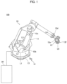
FIG. 1 is a diagram showing the configuration of a robot system according to an embodiment of the present disclosure. -
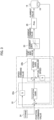
FIG. 2 is a block diagram of a robot controller according to the embodiment of the present disclosure. -
FIG. 3 is a control block diagram of the robot controller according to the embodiment of the present disclosure. -
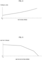
FIG. 4 is a diagram showing a relationship between the rotation speed of a motor and the torque loss of a speed reducer. -
FIG. 5 is a diagram showing a relationship between the rotation speed of the motor and a torque generated from the motor. -
FIG. 6 is a diagram showing limit values that are constant regardless of the rotation speed of the motor. -
FIG. 7 is a diagram showing limit values for forward efficiency and for reverse efficiency that are constant regardless of the rotation speed of the motor. -
FIG. 8 is a diagram showing limit values for the forward efficiency and for the reverse efficiency that vary according to the rotation speed of the motor. -
FIG. 9 is a diagram showing limit values for the forward efficiency and for the reverse efficiency when the motor rotates in a positive direction. -
FIG. 10 is a diagram showing limit values for the forward efficiency and for the reverse efficiency when the motor rotates in a negative direction. -
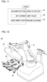
FIG. 11 is a flowchart for illustrating a current limiting method according to the embodiment of the present disclosure. -
FIG. 12 is a diagram showing the configuration of a medical robot according to a modified example. -
FIG. 13 is a block diagram (1) showing the configuration of a robot controller according to a modified example. -
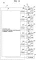
FIG. 14 is a block diagram (2) showing the configuration of a robot controller according to a modified example. - An embodiment embodying the present disclosure is hereinafter described on the basis of the drawings.
- The configuration of a
robot system 100 according to this embodiment is now described with reference toFIGS. 1 to 11 . - As shown in
FIG. 1 , therobot system 100 includes arobot 10 and arobot controller 20 that controls therobot 10. Therobot 10 is a six-axis robot, for example. Furthermore, therobot 10 is an industrial robot, for example. - As shown in
FIG. 1 , therobot 10 includes anarm 11. Thearm 11 includesjoints 12. A plurality ofjoints 12 are provided. For example, six joints 12 (joints 12a to 12f) are provided. Thearm 11 is attached to abase 13. Thejoint 12a is rotatable about an axis L1 extending in a vertical direction. Thejoint 12b is rotatable about an axis L2 extending in a horizontal direction. Thejoint 12c is rotatable about an axis L3 extending parallel to the axis L2. - The
joint 12d is rotatable about an axis L4 perpendicular to the axis L3. Thejoint 12e is rotatable about an axis L5 perpendicular to the axis L4. The joint 12f is rotatable about an axis L6 perpendicular to the axis L5. - As shown in
FIG. 2 ,motors 14a to 14f are provided at thejoints 12a to 12f, respectively.Speed reducers 15a to 15f that transmit the drive forces of themotors 14a to 14f are provided at themotors 14a to 14f, respectively. Each of themotors 14a to 14f generates a force or moment (torque in this embodiment) when a current is carried to the motor, and transmit a drive force via thecorresponding speed reducer speed reducers 15a to 15f slow rotation of themotors 14a to 14f and transmit the rotation of themotors 14a to 14f, respectively. Thus, thejoints 12a to 12f rotate. Themotors 14a to 14f may be collectively referred to as amotor 14 below. In addition, thespeed reducers 15a to 15f may be collectively referred to as aspeed reducer 15 below. The motor 14 (14a to 14f) is an example of a drive. The speed reducer 15 (15a to 15f) is an example of a drive force transmitter. -
Encoders 16a to 16f are provided at themotors 14a to 14f, respectively. Theencoders 16a to 16f detect the angular positions ofoutput shafts 17a to 17f of themotors 14a to 14f, respectively. The detected angular positions of theoutput shafts 17a to 17f are transmitted to a position/speed controller 22 described below. Theencoders 16a to 16f may be collectively referred to as anencoder 16 below. In addition, theoutput shafts 17a to 17f may be collectively referred to as anoutput shaft 17 below. - The
robot controller 20 includes a current limitingdevice 21 that limits a current to be carried to themotor 14 that transmits a drive force via thespeed reducer 15. The current limitingdevice 21 includes the position/speed controller 22 and acurrent limiter 23 that limits the current to be carried to themotor 14 within a limit value range. - The position/
speed controller 22 is electrically connected to each of themotors 14a to 14f, and carries a current to each of themotors 14a to 14f to control a torque output from each of themotors 14a to 14f. The position/speed controller 22 includes aposition controller 22a (seeFIG. 3 ) and aspeed controller 22b (seeFIG. 3 ). Astorage 24 is connected to the position/speed controller 22. Thestorage 24 stores a program for driving each of themotors 14a to 14f. - The
current limiter 23 includescurrent limiters 23a to 23f provided for a plurality ofmotors 14a to 14f, respectively.Amplifiers 25a to 25f are provided between thecurrent limiters 23a to 23f and themotors 14a to 14f, respectively. Theamplifiers 25a to 25f may be collectively referred to as anamplifier 25 below. - Control of the torque of the
motor 14 is now described with reference toFIG. 3 . - The position/
speed controller 22 acquires a position command value (time history command position) of the joint 12 from the storage 24 (upper command device). Then, theposition controller 22a calculates a deviation between the acquired position command value and the angular position (actual angular position) obtained from theencoder 16 of the joint 12. Then, theposition controller 22a multiplies the calculated deviation by a position gain. Theposition controller 22a also differentiates the position command value to calculate a speed command value, which is the target speed of the joint 12. - Then, the
speed controller 22b adds the deviation multiplied by the position gain and the generated speed command value and subtracts the actual angular speed obtained by differentiating the actual angular position from the added value to calculate a speed deviation. Then, thespeed controller 22b multiplies the calculated speed deviation by a speed gain. Thus, thespeed controller 22b generates a target current value corresponding to a target torque output from themotor 14. - Then, the
speed controller 22b transmits the generated target current value to thecurrent limiter 23. When the transmitted target current value is within a current limit value range, thecurrent limiter 23 directly transmits the target current value to theamplifier 25. On the other hand, when the transmitted target current value is outside the current limit value range, thecurrent limiter 23 limits the target current value to a value within the current limit value range and transmits the target current value to theamplifier 25. - In this embodiment, the limit value of the current to be carried to the
motor 14 is set to change according to the speed of the motor 14 (seeFIG. 8 ). One of the reasons for setting the current limit value is to make the torque output by themotor 14 equal to or less than an allowable torque of a drive system (such as a torque to reduce or prevent damage to the speed reducer 15). - On the other hand, as shown in
FIG. 4 , as the rotation speed (horizontal axis) of thespeed reducer 15 increases, the torque loss (vertical axis) of thespeed reducer 15 increases. Specifically, in thespeed reducer 15, Coulomb friction and viscous friction occur. The Coulomb friction is proportional to a force applied to thespeed reducer 15. The viscous friction is caused by the viscosity of grease or oil contained in thespeed reducer 15 and increases as the rotation speed of thespeed reducer 15 increases. - As shown in
FIG. 5 , the torque (vertical axis) generated by themotor 14 decreases as the rotation speed (horizontal axis) of themotor 14 increases. This is because as the rotation speed (number of rotations) of themotor 14 increases, a back electromotive force generated in themotor 14 increases, and it becomes difficult for a current to flow through themotor 14. - As shown in
FIG. 6 , when the current limit value is constant regardless of the rotation speed of themotor 14, in a region in which the rotation speed of themotor 14 is relatively high, the torque loss of thespeed reducer 15 increases and the torque generated by themotor 14 decreases, and thus a desired torque cannot be generated from thespeed reducer 15. - Therefore, in this embodiment, as shown in
FIG. 8 , the absolute value of the limit value is set to increase (in the case of forward efficiency described below) or decrease (in the case of reverse efficiency described below) as the speed (rotation speed) of themotor 14 increases. Furthermore, the absolute value of the limit value is set to gradually increase or decrease as the rotation speed of themotor 14 increases. When the torque loss of thespeed reducer 15 is caused only by friction, the absolute value of the limit value gradually increases or decreases as the rotation speed of themotor 14 increases. However, depending on the control of themotor 14, the absolute value of the limit value may be decreased according to the rotation speed of themotor 14, and the absolute value may be increased after a certain rotation speed. - As shown in
FIG. 4 , the rate of increase in the torque loss of thespeed reducer 15 increases as the rotation speed of thespeed reducer 15 increases. As shown inFIG. 5 , the rate of decrease in the torque generated by themotor 14 increases as the rotation speed of thespeed reducer 15 increases. Therefore, in this embodiment, the rate of change of the limit value is set to increase as the speed (rotation speed) of themotor 14 increases. The rate of change of the limit value inFIG. 8 is an example, and the rate of change of the limit value may not increase as the speed (rotation speed) of themotor 14 increases. That is, the rate of change of the limit value is set to follow a change in the torque loss of thespeed reducer 15. - A case in which the driving direction (rotating direction) of the
motor 14 and the direction of the force or moment (torque in this embodiment) output from themotor 14 are the same as each other is referred to as the forward efficiency. In other words, in the case of the forward efficiency, a torque is transmitted from themotor 14 side to thespeed reducer 15 side in themotor 14 and thespeed reducer 15. The forward efficiency corresponds to a case in which the rotation of the joint 12 is accelerated by themotor 14, for example. At the time of forward efficiency, the torque loss of thespeed reducer 15 contributes negatively to the torque generated by themotor 14. - A case in which the driving direction (rotating direction) of the
motor 14 and the direction of the force or moment (torque in this embodiment) output from themotor 14 are opposite to each other is referred to as the reverse efficiency. In other words, in the case of the reverse efficiency, a torque is transmitted from the output side of thespeed reducer 15 to themotor 14 side. The reverse efficiency corresponds to a case in which the deceleration of themotor 14 is large, for example. At the time of reverse efficiency, the torque loss of thespeed reducer 15 contributes positively to the torque generated by themotor 14. Thus, the contribution of the torque loss of thespeed reducer 15 to the torque generated by themotor 14 differs between the forward efficiency and the reverse efficiency. - Therefore, in this embodiment, as shown in
FIG. 8 , the current limit value includes a limit value for the forward efficiency in which the driving direction (rotating direction) of themotor 14 and the direction of the force or moment (torque in this embodiment) output from themotor 14 are the same as each other, and a limit value for the reverse efficiency having a value different from the limit value for the forward efficiency, in which the driving direction (rotating direction) of themotor 14 and the direction of the force or moment (torque in this embodiment) output from themotor 14 are opposite to each other. The limit value for the forward efficiency and the limit value for the reverse efficiency are set to change according to the speed (rotation speed) of themotor 14. The absolute value of the limit value for the forward efficiency is greater than the absolute value of the limit value for the reverse efficiency. - As shown in
FIG. 7 , when the limit value for the forward efficiency is constant regardless of the rotation speed of themotor 14, the torque loss of thespeed reducer 15, which contributes negatively, increases as the rotation speed of themotor 14 increases, and the torque on the output side of thespeed reducer 15 decreases. When the limit value for the reverse efficiency is constant regardless of the rotation speed of themotor 14, the torque loss of thespeed reducer 15, which contributes positively, increases as the rotation speed of themotor 14 increases, and a relatively large torque is applied to thespeed reducer 15. Therefore, thespeed reducer 15 may be damaged, a bolt of thespeed reducer 15 may be loosened, and the load (stress) on the arm may increase during deceleration. - Therefore, in this embodiment, as shown in
FIG. 8 , the absolute value of the limit value for the forward efficiency is set to increase as the rotation speed of themotor 14 increases, and the absolute value of the limit value for the reverse efficiency is set to decrease as the rotation speed ofmotor 14 increases. - As described above, the rate of increase in the torque loss of the
speed reducer 15 increases as the rotation speed of thespeed reducer 15 increases (seeFIG. 4 ). Furthermore, the rate of decrease in the torque generated by themotor 14 increases as the rotation speed of themotor 14 increases (seeFIG. 5 ). Therefore, in this embodiment, the rate of increase in the limit value for the forward efficiency and the rate of decrease in the limit value for the reverse efficiency are set to increase as the rotation speed of themotor 14 increases. - Specifically, as shown in
FIG. 9 , when a current is carried to themotor 14 in a positive direction (the current command value is positive) and themotor 14 rotates is in the positive direction (forward efficiency), the limit value for the forward efficiency is positive, and increases as the rotation speed of themotor 14 increases. When a current is carried to themotor 14 in the positive direction (the current command value is positive) and themotor 14 rotates in a negative direction (reverse efficiency), the limit value for the reverse efficiency is positive, and decreases as the rotation speed of themotor 14 increases. - As shown in
FIG. 10 , when a current is carried to themotor 14 in the negative direction (the current command value is negative) and themotor 14 rotates in the negative direction (forward efficiency), the limit value for the forward efficiency is negative, and decreases (its absolute value increases) as the rotation speed of themotor 14 increases. When a current is carried to themotor 14 in the negative direction (the current command value is negative) and themotor 14 rotates in the positive direction (reverse efficiency), the limit value for the reverse efficiency is negative, and increases (its absolute value decreases) as the rotation speed of themotor 14 increases. - In this embodiment, the limit value is set to reduce or prevent damage to the
speed reducer 15 due to the force or moment (torque in this embodiment) generated by themotor 14 and maintain the force or moment (torque in this embodiment) on the output side of thespeed reducer 15 at a constant value. Specifically, the limit value for the forward efficiency is set such that the torque on the output side of thespeed reducer 15 is maintained constant even when the rotation speed of themotor 14 increases. In other words, the limit value for the forward efficiency is set to compensate for the torque loss of thespeed reducer 15 and a decrease in the torque generated by the motor 14 (and to reduced or prevent damage to the speed reducer 15). The limit value for the reverse efficiency is set to reduce or prevent damage to thespeed reducer 15 due to an increase in the torque loss of thespeed reducer 15 even when the rotation speed of themotor 14 increases. Themotor 14 is actually driven, and the torque loss of thespeed reducer 15 and the decrease in the torque of themotor 14 are measured such that the limit value for the forward efficiency and the limit value for the reverse efficiency are acquired based on the results of these measurements. - A current limiting method for limiting the current to be carried to the
motor 14 that transmits a drive force via thespeed reducer 15 is now described with reference toFIG. 11 . - In step S1, the current limiting
device 21 acquires the speed (rotation speed) of themotor 14. Specifically, the speed (command speed) is acquired by differentiating the time history command position from the upper command device. The rotation speed of themotor 14 may be acquired based on the angular position of theoutput shaft 17 of themotor 14 acquired from theencoder 16. - In step S2, the
current limiter 23 sets the limit value of the current to be carried to themotor 14 based on the acquired speed (rotation speed) of themotor 14. - In step S3, the
current limiter 23 carries a current to themotor 14 within the set limit value range. The operations in step S1 to step S3 are repeated while themotor 14 is in operation. - According to this embodiment, the following advantages are achieved.
- According to this embodiment, as described above, the limit value of the current to be carried to the
motor 14 is set to change according to the rotation speed of themotor 14. Accordingly, the limit value can be changed according to the loss of thespeed reducer 15 that changes according to the rotation speed (speed) of themotor 14 and the decrease in the torque generated by themotor 14. Consequently, in a configuration in which an upper limit is set for the current to be carried to themotor 14, the desired torque can be output from thespeed reducer 15 even when the rotation speed of themotor 14 increases. - According to this embodiment, as described above, the absolute value of the limit value is set to increase or decrease as the rotation speed of the
motor 14 increases. The loss of thespeed reducer 15 may contribute positively (reverse efficiency) or negatively (forward efficiency) to the torque generated by themotor 14. Therefore, when the loss of thespeed reducer 15 contributes negatively to the force generated by themotor 14, the limit value for the forward efficiency is increased as the rotation speed of themotor 14 increases such that the current to be carried to themotor 14 can be adjusted so as to compensate for the decrease in the torque generated by themotor 14 and the loss of thespeed reducer 15. When the loss of thespeed reducer 15 contributes positively to the force generated by themotor 14, the limit value for the reverse efficiency is decreased as the rotation speed of themotor 14 increases such that the current to be carried to themotor 14 can be adjusted so as to remove an amount by which the loss of thespeed reducer 15 contributes positively. Consequently, the current to be carried to themotor 14 can be appropriately adjusted both when the loss of thespeed reducer 15 contributes positively and when it contributes negatively. - According to this embodiment, as described above, the rate of change of the limit value is set to increase as the rotation speed of the
motor 14 increases. Accordingly, the rate of change of the loss of thespeed reducer 15 and the rate of change of the decrease in the torque generated by themotor 14 increase as the rotation speed of themotor 14 increases, and thus the rate of change of the limit value is set to increase as the rotation speed of themotor 14 increases such that the current to be carried to themotor 14 can be more appropriately adjusted. Consequently, the torque of themotor 14 can be appropriately adjusted. - According to this embodiment, as described above, the current limit value includes the limit value for the forward efficiency in which the driving direction (rotating direction) of the
motor 14 and the direction of the force or moment (torque in this embodiment) output from themotor 14 are the same as each other, and the limit value for the reverse efficiency having a value different from the limit value for the forward efficiency, in which the driving direction (rotating direction) of themotor 14 and the direction of the force or moment (torque in this embodiment) output from themotor 14 are opposite to each other. Furthermore, the limit value for the forward efficiency and the limit value for the reverse efficiency are set to change according to the rotation speed of themotor 14. The loss of thespeed reducer 15 contributes negatively to the force generated by themotor 14 in the case of the forward efficiency, and the loss of thespeed reducer 15 contributes positively to the force generated by themotor 14 in the case of the reverse efficiency. Therefore, as described above, the limit value includes the limit value for the forward efficiency and the limit value for the reverse efficiency having a value different from the limit value for the forward efficiency such that in both cases of the forward efficiency and the reverse efficiency, the current to be carried to themotor 14 can be appropriately adjusted. - According to this embodiment, as described above, the absolute value of the limit value for the forward efficiency is set to increase as the rotation speed of the
motor 14 increases, and the absolute value of the limit value for the reverse efficiency is set to decrease as the rotation speed of themotor 14 increases. Accordingly, in the case of the forward efficiency, the loss of thespeed reducer 15 contributes negatively to the torque generated by themotor 14, and thus the absolute value of the limit value for the forward efficiency is set to increase as the rotation speed of themotor 14 increases such that the current to be carried to themotor 14 can be appropriately adjusted to compensate for the decrease in the torque generated by themotor 14 and the loss of thespeed reducer 15. In the case of the reverse efficiency, the loss of thespeed reducer 15 contributes positively to the torque generated by themotor 14, and thus the absolute value of the limit value for the reverse efficiency is set to decrease as the rotation speed of themotor 14 increases such that damage to thespeed reducer 15 due to application of an excessive torque to thespeed reducer 15 can be reduced or prevented. - According to this embodiment, as described above, the rate of increase in the limit value for the forward efficiency and the rate of decrease in the limit value for the reverse efficiency are set to increase as the rotation speed of the
motor 14 increases. Accordingly, the rate of increase in the loss of thespeed reducer 15 and the rate of decrease in the torque generated by themotor 14 increase as the rotation speed of themotor 14 increases, and thus the rate of increase in the limit value for the forward efficiency and the rate of decrease in the limit value for the reverse efficiency are set to increase as the rotation speed of themotor 14 increases such that the current to be carried to themotor 14 can be more appropriately adjusted. - According to this embodiment, as described above, the limit value is set to change according to the rotation speed of the
motor 14. Accordingly, the limit value can be changed according to the torque loss of thespeed reducer 15 that changes according to the rotation speed of themotor 14 and the decrease in the torque generated by themotor 14. Consequently, when the rotation speed of themotor 14 increases, the current to be carried to themotor 14 can be adjusted to account for the loss of thespeed reducer 15 and the decrease in the torque generated by themotor 14, and thus a desired torque can be output from thespeed reducer 15 even when the rotation speed of themotor 14 increases. - According to this embodiment, as described above, the limit value is set to reduce or prevent damage to the
speed reducer 15 due to the torque generated by themotor 14 and to maintain the torque on the output side of thespeed reducer 15 at a constant value. Accordingly, a desired torque can be output from thespeed reducer 15 while damage to thespeed reducer 15 is reduced or prevented. - According to this embodiment, as described above, the
motor 14 is provided at the joint 12 of therobot 10. Accordingly, even when the rotation speed of themotor 14 provided at the joint 12 of therobot 10 increases, a desired torque can be output from thespeed reducer 15. - The embodiment disclosed this time must be considered as illustrative in all points and not restrictive. The scope of the present disclosure is not shown by the above description of the embodiment but by the scope of claims for patent, and all modifications (modified examples) within the meaning and scope equivalent to the scope of claims for patent are further included.
- For example, while the example in which the present disclosure is applied to the
industrial robot 10 has been shown in the aforementioned embodiment, the present disclosure is not limited to this. For example, as shown inFIG. 12 , the present disclosure may be applied to amedical robot 30. Therobot 30 includes a positioner 31 (articulated robot), anarm base 32, and a plurality ofarms 33. Asurgical instrument 34 is attached to the tip end of each of the plurality ofarms 33. The current limiting device of the present disclosure limits a current to be carried to the positioner 31 (articulated robot) and motors at joints of thearms 33, for example. Thus, in themedical robot 30, even when the speed (rotation speed) of themotor 14 increases, a desired torque can be output from thespeed reducer 15. - In particular, the
medical robot 30 has a limited space for arranging themedical robot 30, includes many joints, and needs to have a low drive voltage to reduce the impact at the time of collision, for example, and thus a low-output motor 14 may be used with a high reduction ratio. In this case, the influence of the friction of a drive system increases, and thus it is particularly effective to change the current limit value according to the rotation speed of themotor 14 as in the present disclosure. - While the example in which the
motor 14 is applied as the "drive" of the present disclosure has been shown in the aforementioned embodiment, the present disclosure is not limited to this. For example, an actuator such as a proportional solenoid, a linear motor, a voice coil, or a spherical actuator may be applied as the "drive" of the present disclosure. Alternatively, a powder clutch/brake or a hysteresis clutch/brake may be applied as the "drive" of the present disclosure. - While the example in which the
speed reducer 15 is applied as the "drive force transmitter" of the present disclosure has been shown in the aforementioned embodiment, the present disclosure is not limited to this. For example, when the motor is a linear motor that moves linearly, the drive force transmitter transmits a force of linear movement of the linear motor. Furthermore, the limit value is set to change according to the linear movement speed of the linear motor. - While the example in which the absolute value of the limit value for the forward efficiency is set to gradually increase as the rotation of the
motor 14 increases, and the absolute value of the limit value for the reverse efficiency is set to gradually decrease as the rotation of themotor 14 increases has been shown in the aforementioned embodiment, the present disclosure is not limited to this. For example, the absolute value of the limit value for the forward efficiency may be set to increase stepwise as the rotation of themotor 14 increases, and the absolute value of the limit value for the reverse efficiency may be set to decrease stepwise as the rotation of themotor 14 increases. - While the example in which the rate of change of the limit value is set to increase as the speed of the motor increases has been shown in the aforementioned embodiment, the present disclosure is not limited to this. For example, when the rate of change of a decrease in the torque generated by the
motor 14 is small (close to linear) with the torque loss of thespeed reducer 15 or an increase in the rotation speed of themotor 14, the rate of change of the limit value may be constant. - While the example in which the limit value for the forward efficiency and the limit value for the reverse efficiency are set has been shown in the aforementioned embodiment, the present disclosure is not limited to this. For example, when a difference between the limit value for the forward efficiency and the limit value for the reverse efficiency is small, a common limit value may be set for both the forward efficiency and the reverse efficiency.
- While the example in which the absolute value of the limit value for the reverse efficiency is set to decrease as the rotation speed of the
motor 14 increases has been shown in the aforementioned embodiment, the present disclosure is not limited to this. For example, depending on the control of themotor 14, the absolute value of the limit value for the reverse efficiency may be set to decrease as the rotation speed of themotor 14 increases in a high-speed range of the rotation speed of themotor 14. - While the example in which the position/
speed controller 22 is provided in common (one) for themotors 14a to 14f has been shown in the aforementioned embodiment, the present disclosure is not limited to this. For example, as shown inFIG. 13 , position/speed controllers 122a to 122f may be provided individually formotors 14a to 14f. - While the example in which the position/
speed controller 22 is provided separately from thecurrent limiter 23a to 23f has been shown in the aforementioned embodiment, the present disclosure is not limited to this. For example, as shown inFIG. 14 , onecontroller 26 including a position/speed controller and a current limiter may be provided. - While the example in which the
current limiter 23 is provided upstream of theamplifier 25 has been shown in the aforementioned embodiment, the present disclosure is not limited to this. In the present disclosure, thecurrent limiter 23 is only required to be provided somewhere (such as on the output side of theamplifier 25 or in a line fed back from the encoder 16) in a line that connects the position/speed controller 22 to themotor 14. Description of Reference Numerals -
- 10: robot
- 12, 12a to 12f: joint
- 14, 14a to 14f: motor (drive)
- 15, 15a to 15f: speed reducer (drive force transmitter)
- 20: robot controller
- 21: current limiting device
- 23, 23a to 23f: current limiter
- 30: robot (medical robot)
- 100: robot system
Claims (12)
- A current limiting device to limit a current to be carried to a drive that generates a force or moment when the current is carried to the drive and transmits a drive force via a drive force transmitter, the current limiting device comprising:a current limiter to limit the current to be carried to the drive within a range of a limit value; whereinthe limit value is set to change according to a speed of the drive.
- The current limiting device according to claim 1, wherein an absolute value of the limit value is set to increase or decrease as the speed of the drive increases.
- The current limiting device according to claim 2, wherein a rate of change of the limit value is set to increase as the speed of the drive increases.
- The current limiting device according to any one of claims 1 to 3, whereinthe limit value includes a limit value for forward efficiency in which a driving direction of the drive and a direction of the force or moment output from the drive are the same as each other, and a limit value for reverse efficiency having a value different from the limit value for the forward efficiency, in which the driving direction of the drive and the direction of the force or moment output from the drive are opposite to each other; andthe limit value for the forward efficiency and the limit value for the reverse efficiency are set to change according to the speed of the drive.
- The current limiting device according to claim 4, whereinan absolute value of the limit value for the forward efficiency is set to increase as the speed of the drive increases; andan absolute value of the limit value for the reverse efficiency is set to decrease as the speed of the drive increases.
- The current limiting device according to claim 5, wherein
a rate of increase in the limit value for the forward efficiency and a rate of decrease in the limit value for the reverse efficiency are set to increase as the speed of the drive increases. - The current limiting device according to any one of claims 1 to 6, whereinthe drive includes a motor;the drive force transmitter includes a speed reducer to slow rotation of the motor and transmit the rotation; andthe limit value is set to change according to a rotation speed of the motor.
- The current limiting device according to any one of claims 1 to 7, wherein the limit value is set to reduce or prevent damage to the drive force transmitter due to the force or moment generated by the drive and to maintain a force or moment on an output side of the drive force transmitter at a constant value.
- The current limiting device according to any one of claims 1 to 8, wherein the drive includes a motor provided at a joint of a robot.
- The current limiting device according to claim 9, wherein the robot includes a medical robot.
- A robot system comprising:a robot; anda robot controller configured or programmed to control the robot; whereinthe robot includes:a joint;a motor provided at the joint; anda speed reducer to slow rotation of the motor;the robot controller includes a current limiter to limit a current to be carried to the motor within a range of a limit value; andthe limit value is set to change according to a speed of the motor.
- A current limiting method for limiting a current to be carried to a drive that generates a force or moment when the current is carried to the drive and transmits a drive force via a drive force transmitter, the current limiting method comprising:acquiring a speed of the drive;setting a limit value of the current to be carried to the drive based on the acquired speed of the drive; andcarrying the current to the drive within a range of the set limit value.
Applications Claiming Priority (2)
| Application Number | Priority Date | Filing Date | Title |
|---|---|---|---|
| JP2020140784A JP7527890B2 (en) | 2020-08-24 | 2020-08-24 | Current limiting device, robot system, and current limiting method |
| PCT/JP2021/030549 WO2022044990A1 (en) | 2020-08-24 | 2021-08-20 | Current limiting device, robot system, and current limiting method |
Publications (2)
| Publication Number | Publication Date |
|---|---|
| EP4201605A1 true EP4201605A1 (en) | 2023-06-28 |
| EP4201605A4 EP4201605A4 (en) | 2024-10-02 |
Family
ID=80355228
Family Applications (1)
| Application Number | Title | Priority Date | Filing Date |
|---|---|---|---|
| EP21861417.0A Pending EP4201605A4 (en) | 2020-08-24 | 2021-08-20 | CURRENT LIMITING DEVICE, ROBOT SYSTEM AND CURRENT LIMITING METHOD |
Country Status (6)
| Country | Link |
|---|---|
| US (1) | US12390924B2 (en) |
| EP (1) | EP4201605A4 (en) |
| JP (1) | JP7527890B2 (en) |
| KR (1) | KR102801742B1 (en) |
| CN (1) | CN116323104B (en) |
| WO (1) | WO2022044990A1 (en) |
Families Citing this family (1)
| Publication number | Priority date | Publication date | Assignee | Title |
|---|---|---|---|---|
| JP7829543B2 (en) * | 2023-12-22 | 2026-03-13 | 株式会社安川電機 | Robot system and control method |
Family Cites Families (15)
| Publication number | Priority date | Publication date | Assignee | Title |
|---|---|---|---|---|
| US4776433A (en) * | 1988-01-25 | 1988-10-11 | Westinghouse Electric Corp. | Elevator door control system |
| KR19980073967A (en) | 1997-03-20 | 1998-11-05 | 박영설 | Sole |
| JP3588956B2 (en) | 1997-03-04 | 2004-11-17 | 豊田工機株式会社 | Robot controller |
| KR100242001B1 (en) * | 1997-03-20 | 2000-02-01 | 윤종용 | Method and apparatus for restricting current in switched reluctance motor |
| JP2005287163A (en) * | 2004-03-29 | 2005-10-13 | Makita Corp | Motor device and power tool |
| JP2008073790A (en) * | 2006-09-20 | 2008-04-03 | Toyota Motor Corp | Robot and robot control apparatus and control method |
| JP5443782B2 (en) | 2009-02-24 | 2014-03-19 | 川崎重工業株式会社 | Robot, current limiting device and current limiting method |
| US8183810B2 (en) * | 2009-09-08 | 2012-05-22 | Hoffman Enclosures, Inc. | Method of operating a motor |
| DE102010015407A1 (en) * | 2010-04-19 | 2011-10-20 | Kuka Laboratories Gmbh | Robot and method for operating a robot |
| JP5620527B2 (en) * | 2013-02-05 | 2014-11-05 | 山洋電気株式会社 | Motor control device |
| JP6203701B2 (en) * | 2014-11-13 | 2017-09-27 | 東芝機械株式会社 | Electric machine and program |
| JP6312584B2 (en) * | 2014-12-05 | 2018-04-18 | 山洋電気株式会社 | Motor control device |
| JP6173373B2 (en) * | 2015-02-20 | 2017-08-02 | 京セラドキュメントソリューションズ株式会社 | Motor control device, sheet conveying device, and image forming apparatus |
| JP2016158751A (en) | 2015-02-27 | 2016-09-05 | ソニー株式会社 | Actuator and medical support arm device |
| CN115489246B (en) * | 2022-10-18 | 2024-06-28 | 北京理工大学 | An electro-hydraulic driven vibration reduction device and a wheel-legged robot having the same |
-
2020
- 2020-08-24 JP JP2020140784A patent/JP7527890B2/en active Active
-
2021
- 2021-08-20 CN CN202180051813.1A patent/CN116323104B/en active Active
- 2021-08-20 KR KR1020237010118A patent/KR102801742B1/en active Active
- 2021-08-20 EP EP21861417.0A patent/EP4201605A4/en active Pending
- 2021-08-20 US US18/022,566 patent/US12390924B2/en active Active
- 2021-08-20 WO PCT/JP2021/030549 patent/WO2022044990A1/en not_active Ceased
Also Published As
| Publication number | Publication date |
|---|---|
| KR20230054875A (en) | 2023-04-25 |
| KR102801742B1 (en) | 2025-04-28 |
| JP2022036526A (en) | 2022-03-08 |
| CN116323104A (en) | 2023-06-23 |
| WO2022044990A1 (en) | 2022-03-03 |
| US12390924B2 (en) | 2025-08-19 |
| JP7527890B2 (en) | 2024-08-05 |
| US20230405814A1 (en) | 2023-12-21 |
| CN116323104B (en) | 2025-12-12 |
| EP4201605A4 (en) | 2024-10-02 |
Similar Documents
| Publication | Publication Date | Title |
|---|---|---|
| JP4294646B2 (en) | Robot arm control method and control apparatus | |
| US10792821B2 (en) | Method and device for decelerating a robot axis arrangement | |
| EP4213374A1 (en) | Current limiting device, robot system, and current limiting method | |
| EP2361736B1 (en) | Rotary drive device | |
| US12472623B2 (en) | Robot, drive unit for a robot and positioning method | |
| EP2230053A2 (en) | Industrial robot and control method | |
| US12390924B2 (en) | Current limiting device, robot system, and current limiting method | |
| EP3520972B1 (en) | Robot controlling method and welding method | |
| JPH11143548A (en) | Electric motor friction compensation method | |
| JP2010194645A (en) | Robot, and device and method for current limiting | |
| WO2018173634A1 (en) | Power transmission system in mechanical device | |
| JP2022036526A5 (en) | ||
| RU2359306C2 (en) | Self-adapting electric drive of robot | |
| RU2783736C1 (en) | Automatic control device for electromechanical system with gap in kinematic transmission (options) | |
| JP7489591B1 (en) | Robot control method and robot control device | |
| US20250058465A1 (en) | Robot control device, control method, and non-transitory storage medium | |
| JP7474935B2 (en) | Robot control method and robot control device | |
| JP7502781B2 (en) | Robot arm control system | |
| JP2018148661A (en) | Motor control system | |
| JP2022161438A (en) | ROBOT DEVICE, CONTROL METHOD, PRODUCT MANUFACTURING METHOD, CONTROL PROGRAM, RECORDING MEDIUM | |
| JPH1142578A (en) | Robot control method and device |
Legal Events
| Date | Code | Title | Description |
|---|---|---|---|
| STAA | Information on the status of an ep patent application or granted ep patent |
Free format text: STATUS: THE INTERNATIONAL PUBLICATION HAS BEEN MADE |
|
| PUAI | Public reference made under article 153(3) epc to a published international application that has entered the european phase |
Free format text: ORIGINAL CODE: 0009012 |
|
| STAA | Information on the status of an ep patent application or granted ep patent |
Free format text: STATUS: REQUEST FOR EXAMINATION WAS MADE |
|
| 17P | Request for examination filed |
Effective date: 20230216 |
|
| AK | Designated contracting states |
Kind code of ref document: A1 Designated state(s): AL AT BE BG CH CY CZ DE DK EE ES FI FR GB GR HR HU IE IS IT LI LT LU LV MC MK MT NL NO PL PT RO RS SE SI SK SM TR |
|
| DAV | Request for validation of the european patent (deleted) | ||
| DAX | Request for extension of the european patent (deleted) | ||
| REG | Reference to a national code |
Ref country code: DE Ref legal event code: R079 Free format text: PREVIOUS MAIN CLASS: B25J0009120000 Ipc: B25J0009160000 |
|
| A4 | Supplementary search report drawn up and despatched |
Effective date: 20240903 |
|
| RIC1 | Information provided on ipc code assigned before grant |
Ipc: H02P 29/40 20160101ALI20240828BHEP Ipc: B25J 9/16 20060101AFI20240828BHEP |
|
| GRAP | Despatch of communication of intention to grant a patent |
Free format text: ORIGINAL CODE: EPIDOSNIGR1 |
|
| STAA | Information on the status of an ep patent application or granted ep patent |
Free format text: STATUS: GRANT OF PATENT IS INTENDED |
|
| RIC1 | Information provided on ipc code assigned before grant |
Ipc: B25J 9/16 20060101AFI20260329BHEP Ipc: H02P 29/40 20160101ALI20260329BHEP |
|
| INTG | Intention to grant announced |
Effective date: 20260422 |
|
| GRAJ | Information related to disapproval of communication of intention to grant by the applicant or resumption of examination proceedings by the epo deleted |
Free format text: ORIGINAL CODE: EPIDOSDIGR1 |
|
| STAA | Information on the status of an ep patent application or granted ep patent |
Free format text: STATUS: REQUEST FOR EXAMINATION WAS MADE |
|
| GRAP | Despatch of communication of intention to grant a patent |
Free format text: ORIGINAL CODE: EPIDOSNIGR1 |
|
| STAA | Information on the status of an ep patent application or granted ep patent |
Free format text: STATUS: GRANT OF PATENT IS INTENDED |
|
| INTC | Intention to grant announced (deleted) |