EP4201540A1 - Waste treatment system and waste treatment method - Google Patents
Waste treatment system and waste treatment method Download PDFInfo
- Publication number
- EP4201540A1 EP4201540A1 EP21872419.3A EP21872419A EP4201540A1 EP 4201540 A1 EP4201540 A1 EP 4201540A1 EP 21872419 A EP21872419 A EP 21872419A EP 4201540 A1 EP4201540 A1 EP 4201540A1
- Authority
- EP
- European Patent Office
- Prior art keywords
- reformer
- steam
- waste
- treatment system
- waste treatment
- Prior art date
- Legal status (The legal status is an assumption and is not a legal conclusion. Google has not performed a legal analysis and makes no representation as to the accuracy of the status listed.)
- Pending
Links
Images




Classifications
-
- B—PERFORMING OPERATIONS; TRANSPORTING
- B09—DISPOSAL OF SOLID WASTE; RECLAMATION OF CONTAMINATED SOIL
- B09B—DISPOSAL OF SOLID WASTE NOT OTHERWISE PROVIDED FOR
- B09B3/00—Destroying solid waste or transforming solid waste into something useful or harmless
- B09B3/60—Biochemical treatment, e.g. by using enzymes
-
- B—PERFORMING OPERATIONS; TRANSPORTING
- B09—DISPOSAL OF SOLID WASTE; RECLAMATION OF CONTAMINATED SOIL
- B09B—DISPOSAL OF SOLID WASTE NOT OTHERWISE PROVIDED FOR
- B09B3/00—Destroying solid waste or transforming solid waste into something useful or harmless
- B09B3/40—Destroying solid waste or transforming solid waste into something useful or harmless involving thermal treatment, e.g. evaporation
- B09B3/45—Steam treatment, e.g. supercritical water gasification or oxidation
-
- C—CHEMISTRY; METALLURGY
- C02—TREATMENT OF WATER, WASTE WATER, SEWAGE, OR SLUDGE
- C02F—TREATMENT OF WATER, WASTE WATER, SEWAGE, OR SLUDGE
- C02F11/00—Treatment of sludge; Devices therefor
- C02F11/02—Biological treatment
- C02F11/04—Anaerobic treatment; Production of methane by such processes
-
- C—CHEMISTRY; METALLURGY
- C02—TREATMENT OF WATER, WASTE WATER, SEWAGE, OR SLUDGE
- C02F—TREATMENT OF WATER, WASTE WATER, SEWAGE, OR SLUDGE
- C02F11/00—Treatment of sludge; Devices therefor
- C02F11/12—Treatment of sludge; Devices therefor by de-watering, drying or thickening
- C02F11/13—Treatment of sludge; Devices therefor by de-watering, drying or thickening by heating
-
- C—CHEMISTRY; METALLURGY
- C02—TREATMENT OF WATER, WASTE WATER, SEWAGE, OR SLUDGE
- C02F—TREATMENT OF WATER, WASTE WATER, SEWAGE, OR SLUDGE
- C02F11/00—Treatment of sludge; Devices therefor
- C02F11/18—Treatment of sludge; Devices therefor by thermal conditioning
-
- C—CHEMISTRY; METALLURGY
- C12—BIOCHEMISTRY; BEER; SPIRITS; WINE; VINEGAR; MICROBIOLOGY; ENZYMOLOGY; MUTATION OR GENETIC ENGINEERING
- C12M—APPARATUS FOR ENZYMOLOGY OR MICROBIOLOGY; APPARATUS FOR CULTURING MICROORGANISMS FOR PRODUCING BIOMASS, FOR GROWING CELLS OR FOR OBTAINING FERMENTATION OR METABOLIC PRODUCTS, i.e. BIOREACTORS OR FERMENTERS
- C12M23/00—Constructional details, e.g. recesses, hinges
- C12M23/58—Reaction vessels connected in series or in parallel
-
- C—CHEMISTRY; METALLURGY
- C12—BIOCHEMISTRY; BEER; SPIRITS; WINE; VINEGAR; MICROBIOLOGY; ENZYMOLOGY; MUTATION OR GENETIC ENGINEERING
- C12M—APPARATUS FOR ENZYMOLOGY OR MICROBIOLOGY; APPARATUS FOR CULTURING MICROORGANISMS FOR PRODUCING BIOMASS, FOR GROWING CELLS OR FOR OBTAINING FERMENTATION OR METABOLIC PRODUCTS, i.e. BIOREACTORS OR FERMENTERS
- C12M41/00—Means for regulation, monitoring, measurement or control, e.g. flow regulation
- C12M41/12—Means for regulation, monitoring, measurement or control, e.g. flow regulation of temperature
- C12M41/18—Heat exchange systems, e.g. heat jackets or outer envelopes
-
- C—CHEMISTRY; METALLURGY
- C12—BIOCHEMISTRY; BEER; SPIRITS; WINE; VINEGAR; MICROBIOLOGY; ENZYMOLOGY; MUTATION OR GENETIC ENGINEERING
- C12M—APPARATUS FOR ENZYMOLOGY OR MICROBIOLOGY; APPARATUS FOR CULTURING MICROORGANISMS FOR PRODUCING BIOMASS, FOR GROWING CELLS OR FOR OBTAINING FERMENTATION OR METABOLIC PRODUCTS, i.e. BIOREACTORS OR FERMENTERS
- C12M41/00—Means for regulation, monitoring, measurement or control, e.g. flow regulation
- C12M41/40—Means for regulation, monitoring, measurement or control, e.g. flow regulation of pressure
-
- F—MECHANICAL ENGINEERING; LIGHTING; HEATING; WEAPONS; BLASTING
- F22—STEAM GENERATION
- F22B—METHODS OF STEAM GENERATION; STEAM BOILERS
- F22B1/00—Methods of steam generation characterised by form of heating method
- F22B1/02—Methods of steam generation characterised by form of heating method by exploitation of the heat content of hot heat carriers
- F22B1/18—Methods of steam generation characterised by form of heating method by exploitation of the heat content of hot heat carriers the heat carrier being a hot gas, e.g. waste gas such as exhaust gas of internal-combustion engines
-
- B—PERFORMING OPERATIONS; TRANSPORTING
- B09—DISPOSAL OF SOLID WASTE; RECLAMATION OF CONTAMINATED SOIL
- B09B—DISPOSAL OF SOLID WASTE NOT OTHERWISE PROVIDED FOR
- B09B2101/00—Type of solid waste
- B09B2101/25—Non-industrial waste, e.g. household waste
-
- C—CHEMISTRY; METALLURGY
- C02—TREATMENT OF WATER, WASTE WATER, SEWAGE, OR SLUDGE
- C02F—TREATMENT OF WATER, WASTE WATER, SEWAGE, OR SLUDGE
- C02F2303/00—Specific treatment goals
- C02F2303/10—Energy recovery
Definitions
- the present disclosure relates to a waste treatment system and a waste treatment method.
- waste is hydrothermally treated (hydrolyzed) with steam by a reformer, and solid fuel is produced from a solid phase of a reactant obtained by the hydrolysis. Further, combustion energy generated by combustion of the solid fuel is used to generate steam, and the generated steam is used to perform the hydrolysis.
- Patent Document 1 JP2013-511386A (translation of a PCT application)
- the present disclosure was made in view of the above problem, and an object thereof is to provide a waste treatment system and a waste treatment method whereby it is possible to promptly meet the steam demand from the reformer.
- a waste treatment system includes: at least one reformer for hydrolyzing waste with steam; a microbial reactor for microbially degrading a reformed material containing at least a solid of the waste hydrolyzed by the at least one reformer; and at least one steam generation device for generating the steam by using only combustion energy of a gas produced in the microbial reactor.
- a waste treatment method includes: a step of hydrolyzing waste with steam; a step of microbially degrading a reformed material containing at least a solid of the hydrolyzed waste; and a step of generating the steam by using only combustion energy of a gas produced in the step of microbially degrading the reformed material.
- FIG. 1 is a schematic configuration diagram of the waste treatment system 1 according to the first embodiment of the present disclosure.
- the waste treatment system 1 according to the first embodiment of the present disclosure includes a reformer 2, a microbial reactor 3, and a steam generation device 4.
- the reformer 2 hydrolyzes waste with steam S1.
- the reformer 2 is configured to receive waste such as municipal waste as it is from a vehicle, a plant, or the like where the waste is collected, and hydrolyze the waste in a batch manner with steam S1, for example.
- the reformer 2 is a batch-type reformer including a housing 10 with an input port 11 through which the waste is input and a discharge port 12 through which the hydrolyzed waste is discharged.
- the input port 11 and the discharge port 12 are provided with opening/closing valves (not shown), and the housing 10 can be sealed by closing the opening/closing valves.
- the hydrolysis of the waste in the reformer 2 may be wet hydrolysis in which steam S1 contacts the waste and heats the waste, or may be dry hydrolysis in which steam S1 indirectly heats the waste without contacting the waste.
- dry hydrolysis moisture in the waste within the housing 10 evaporates into water vapor, and the water vapor uniformly heats the waste within the housing 10. Further, moisture required for hydrolysis is supplied as moisture from the water vapor adheres to the surface of the waste.
- a plurality of reformers 2 may be connected in series, or a plurality of reformers 2 may be connected in parallel, or the configuration where a plurality of reformers 2 are connected in series and the configuration where a plurality of reformers 2 are connected in parallel may be combined.
- the municipal waste which is given as an example of the waste, mainly contains kitchen waste, paper waste, and plastic waste, with a small amount of metal.
- the waste to be treated by the waste treatment system 1 is not limited to municipal waste.
- the waste treatment system 1 can also treat waste such as sludge generated by treating wastewater from factories or the like and agricultural waste with a higher moisture content than municipal waste.
- the microbial reactor 3 microbially degrades a reformed material X1 containing at least a solid of the waste hydrolyzed by the reformer 2. In this process, the microbial reactor 3 produces biogas G1.
- the microbial reactor 3 may have any configuration as long as it uses the reformed material X1 as a raw material and utilizes the biological action of microorganisms to produce biogas G1.
- the microbial reactor 3 may be a biogas fermenter for producing biogas G1 such as methane as valuables.
- the microbial reactor 3 is not limited to the biogas fermenter.
- the microbial reactor 3 may be a saccharification tank for producing sugar as valuables from carbohydrates such as starch and cellulose, or a composting device for producing compost by composting.
- the waste treatment system 1 can treat even waste with low moisture content at low cost.
- the steam generation device 4 generates steam S1 by using only combustion energy of biogas G1 produced in the microbial reactor 3. In other words, the steam generation device 4 does not generate steam S1 by combustion energy of fuel other than biogas G1 produced in the microbial reactor 3. Then, the reformer 2 hydrolyzes waste with steam S1 generated by the steam generation device 4.
- a steam generation device 4 includes, for example, an exhaust gas boiler.
- the exhaust gas boiler generates steam S 1 by heat of exhaust gas generated by combustion of biogas G1.
- the steam generation device 4 is not limited to the exhaust gas boiler.
- the steam generation device 4 may include a combustion boiler for generating steam S1 by using biogas G1 as fuel, instead of the exhaust gas boiler. Alternatively, the steam generation device 4 may include both the exhaust gas boiler and the combustion boiler.
- the reformer 2 performs hydrolysis with steam generated by using only combustion energy of biogas G1 produced in the microbial reactor 3. Thus, it is possible to promptly meet the demand for steam S 1 from the reformer 2.
- the reformer 2 hydrolyzes waste with low moisture content (e.g., municipal waste) to produce the reformed material X1
- microbially degrading solid in the reformed material X1 can yield more biogas G1 than microbially degrading only liquid in the reformed material X1.
- the microbial reactor 3 microbially degrades the reformed material X1 containing at least a solid of the waste hydrolyzed by the reformer 2. Thus, it is possible to increase the production amount of biogas G1.
- the waste treatment system 1 according to the second embodiment is the addition of a heat retention steam pipe 8 to the first embodiment.
- the same constituent element as those in the first embodiment are associated with the same reference numerals and not described again in detail.
- FIG. 2 is a schematic configuration diagram of the waste treatment system 1 according to the second embodiment of the present disclosure. As shown in FIG. 2 , the waste treatment system 1 further includes a heat retention steam pipe 8 connecting the reformer 2 and the microbial reactor 3.
- the reformer 2 supplies exhaust steam S2 to the microbial reactor 3 through the heat retention steam pipe 8.
- the microbial reactor 3 is kept within a predetermined temperature range, for example, between 30 degrees and 50 degrees, by heat of exhaust steam S2 supplied from the reformer 2.
- the microbial reactor 3 is desirably kept within a predetermined temperature range in order to promote the microbial degradation of the reformed material X1.
- exhaust steam S2 is used as a heat source for heat retention of the microbial reactor 3.
- the amount of fuel prepared for heat retention of the microbial reactor 3 can be suppressed, and the operating cost can be reduced.
- the waste treatment system 1 according to the third embodiment is the addition of a drying device 13 and a drying steam pipe 15 to the first embodiment.
- the same constituent elements as those in the first embodiment are associated with the same reference numerals and not described again in detail.
- the waste treatment system 1 according to another embodiment may be the addition of a drying device 13 and a drying steam pipe 15 to the second embodiment.
- FIG. 3 is a schematic configuration diagram of the waste treatment system 1 according to the third embodiment of the present disclosure.
- the waste treatment system 1 further includes a drying device 13 for drying a residue X2 obtained after the microbial reactor 3 microbially degrades the reformed material X1, and a drying steam pipe 15 connecting the reformer 2 and the drying device 13.
- the waste treatment system 1 includes a dehydration device 14 for dehydrating the residue X2 (fermentation residue) that remains after the microbial reactor 3 microbially degrades the reformed material X1.
- the drying device 13 is supplied with the residue X2 dehydrated by the dehydration device 14.
- the reformer 2 supplies exhaust steam S2 to the drying device 13 through the drying steam pipe 15.
- the drying device 13 dries the residue X2 dehydrated by the dehydration device 14 by heat of exhaust steam S2 supplied from the reformer 2.
- the waste treatment system 1 with the microbial reactor 3 may include the drying device 13 for drying the residue X2 obtained from the microbial reactor 3.
- exhaust steam S2 is used as a heat source for drying the residue X2 by the drying device 13.
- the amount of fuel prepared for drying the residue X2 by the drying device 13 can be suppressed, and the operating cost can be reduced.
- the waste treatment system 1 according to the fourth embodiment may be the addition of a separation device 16 to the first embodiment.
- the same constituent elements as those in the first embodiment are associated with the same reference numerals and not described again in detail.
- the waste treatment system 1 according to another embodiment may be the addition of a separation device 16 to the second or third embodiment.
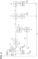
- FIG. 4 is a schematic configuration diagram of the waste treatment system 1 according to the fourth embodiment of the present disclosure. As shown in FIG. 4 , the waste treatment system 1 further includes a separation device 16 disposed between the reformer 2 and the microbial reactor 3.
- the separation device 16 separates an unsuitable substance that is unsuitable for producing biogas G1 in the microbial reactor 3 from the reformed material X1 obtained by hydrolyzing the waste in the reformer 2.
- the separation device 16 serves to separate the reformed material X1 into a large particle size component and a small particle size component having a smaller particle size than the large particle size component.
- the separation device 16 is, for example, a screen having any mesh size, which corresponds to a particle size at a boundary between the large particle size component and the small particle size component.
- the small particle size component is degraded in the microbial reactor 3 to produce valuables.
- the large particle size component is separated from the reformed material X1 and is not supplied to the microbial reactor 3.
- a principal component of the large particle size component has a relatively large particle size even after hydrolysis in the reformer 2, and cannot be degraded in the microbial reactor 3, such as those derived from plastic waste or metal.
- the large particle size component and the small particle size component are, respectively, a reaction-unsuitable substance and a reaction-suitable substance for microbial reaction.
- the waste treatment system 1 includes the above-described dehydration device 14, a reformed material transfer line 22 connecting the reformer 2 and the separation device 16, and a water injection pipe 24 connecting the dehydration device 14 and the reformed material transfer line 22.
- the reformed material transfer line 22 may be a pipe if the reformed material X1 is slurry, or may be a conveyor or the like if the reformed material X1 is solid. Even if the reformed material X1 is solid, as long as the reformed material X1 can be pumped by air or the like, the reformed material transfer line 22 may be a pipe.
- the dehydration device 14 supplies water dehydrated from the residue X2 of the microbial reactor 3 or boiler blowdown to the reformed material X1 in the reformed material transfer line 22 through the water injection pipe 24.
- the water injection pipe 24 is configured as a moisture adjustment device, disposed between the reformer 2 and the microbial reactor 3, for adjusting the moisture content of the reformed material X1.
- the water injection pipe 24 adjusts the moisture content of the reformed material X1 upstream of the separation device 16, but the present disclosure is not limited to this embodiment.
- the water injection pipe 24 may adjust the moisture content of the reformed material X1 downstream of the separation device 16.
- the waste treatment system 1 further includes a moisture amount acquisition device 30 for acquiring the amount of moisture contained in the reformer 2.
- the moisture amount acquisition device 30 acquires the moisture amount contained in the reformer 2, based on statistical data or weight of the raw material supplied to the reformer 2 (including waste properties estimated by machine learning, AI, etc. based on images), consolidation torque, reformer temperature (inside, surface), amount of steam S1 supplied to the reformer 2, time during which steam S1 is supplied to the reformer 2, and amount of temperature change in the reformer 2.
- the moisture amount acquisition device 30 includes a flow meter 30A for acquiring the amount of steam S1 supplied to the reformer 2, a thermometer 30B for acquiring the temperature in the reformer 2, a timer 30C, and a control device 30D.
- the control device 30D is electrically connected to each of the flow meter 30A, the thermometer 30B, and the timer 30C, and calculates (acquires) the moisture amount contained in the reformer 2, based on data acquired by each of the flow meter 30A, the thermometer 30B, and the timer 30C.
- the moisture amount acquisition device 30 is not limited to the embodiment illustrated in FIG. 4 as long as it can acquire the moisture amount in the reformer 2.
- the moisture amount acquisition device 30 may be a near-infrared, microwave, or capacitance moisture meter.
- the water injection pipe 24 adjusts the moisture content of the reformed material X1 based on the moisture amount acquired by the moisture amount acquisition device 30.
- the water injection pipe 24 is provided with a regulating valve 32 for adjusting the amount of water (water dehydrated from the residue X2 of the microbial reactor 3 or boiler blowdown) supplied from the dehydration device 14 to the reformed material transfer line 22.
- the regulating valve 32 is electrically connected to the control device 30D, and the opening degree thereof is adjusted according to instructions from the control device 30D.
- the waste treatment system 1 includes a gas holder 18 for storing biogas G1 produced in the microbial reactor 3, a gas engine 20 driven with biogas G1 stored in the gas holder 18 as fuel, an exhaust gas boiler 4A (4) for generating steam S1 by heat of exhaust gas G4 from the gas engine 20, and a combustion boiler 4B (4) for generating steam S1 with biogas G1 stored in the gas holder 18 as fuel.
- Biogas G1 stored in the gas holder 18 is supplied to the gas engine 20.
- the gas engine 20 is connected to a generator body part (power generation device) (not shown).
- the generator body part generates power by using combustion energy generated by combustion of biogas G1. In this process, the gas engine 20 emits exhaust gas G4.
- Exhaust gas G4 from the gas engine 20 is supplied to the exhaust gas boiler 4A.
- the exhaust gas boiler 4A (first steam generation device) serves to generate steam S1 supplied to the reformer 2.
- the exhaust gas boiler 4A generates steam S1 by using only combustion energy of biogas G1, i.e., heat of exhaust gas G4.
- Biogas G1 stored in the gas holder 18 is also supplied to the combustion boiler 4B (second steam generation device).
- the combustion boiler 4B serves to generate steam S1 supplied to the reformer 2.
- the combustion boiler 4B uses biogas G1 as fuel and generates steam S1 by using only combustion energy of biogas G1.
- the separation device 16 is disposed between the reformer 2 and the microbial reactor 3, it is possible to reduce the amount of the unsuitable substance supplied to the microbial reactor 3. As a result, it is possible to reduce the risk of inhibiting production of biogas G1 in the microbial reactor 3, and to efficiently produce biogas G1 in the microbial reactor 3.
- the total solid concentration (TS) of the reformed material X1 obtained by hydrolysis in the reformer 2 can be adjusted to improve the efficiency of production of biogas G1 in the microbial reactor 3. Further, since water obtained by dehydration of the residue X2 of the microbial reactor 3 contains ammonia, if the reformed material X1 has low nitrogen content, the reformed material X1 can also be replenished with a nitrogen-containing substance.
- the moisture amount in the reformer 2 can be obtained with high accuracy from the amount of steam S1 supplied to the reformer 2, time during which steam S1 is supplied to the reformer 2, and amount of temperature change in the reformer 2.
- the waste treatment system 1 further includes the moisture amount acquisition device 30 for acquiring the moisture amount contained in the reformer 2
- the moisture amount contained in the reformer 2 can be obtained with high accuracy, so it is possible to further improve the efficiency of production of biogas G1 in the microbial reactor 3.
- the total solid concentration (TS) of the reformed material X1 is adjusted based on the moisture amount contained in the reformer 2 acquired by the moisture amount acquisition device 30 (calculated by the control device 30D), it is possible to further improve the efficiency of production of biogas G1 in the microbial reactor 3.
- the exhaust gas boiler 4A and the combustion boiler 4B do not necessarily have the same capacity to generate steam S 1.
- Steam S1 is generated in at least one of the exhaust gas boiler 4A or the combustion boiler 4B according to the steam demand from the reformer 2.
- the steam demand from the reformer 2 is calculated, for example, based on the amount of waste fed into the reformer 2 and the moisture content of the waste.
- the other of the exhaust gas boiler 4A or the combustion boiler 4B may be put on standby, or steam may be generated for purposes other than supply to the reformer 2. If it is difficult to meet the steam demand from the reformer 2 by only the supply of steam S1 generated in one of the exhaust gas boiler 4A or the combustion boiler 4B, the shortage may be made up with steam S1 generated in the other of the exhaust gas boiler 4A or the combustion boiler 4B. Thus, efficient operation of the waste treatment system 1 can be realized.
- the operation method for each of the exhaust gas boiler 4A and the combustion boiler 4B is not particularly limited, an example of the operation method will be described. While the waste is hydrolyzed in the reformer 2, the exhaust gas boiler 4A is always operated. If the hydrolysis conditions in the reformer 2 can be adjusted only by steam S1 generated in the exhaust gas boiler 4A, the combustion boiler 4B is not operated. When the hydrolysis conditions are adjusted according to the amount of waste fed to the reformer 2 or the composition of waste components, if steam S1 generated in the exhaust gas boiler 4A alone is insufficient, the combustion boiler 4B is operated to supply not only steam S1 generated in the exhaust gas boiler 4A but also steam S1 generated in the combustion boiler 4B to the reformer 2.
- the waste treatment system 1 according to the fifth embodiment is limited to the case where a plurality of reformers 2 are provided, and differs from the first to fourth embodiments in this point.
- the same constituent element as those in the first to fourth embodiments are associated with the same reference numerals and not described again in detail.
- FIG. 5 is a schematic configuration diagram of the waste treatment system 1 according to the fifth embodiment of the present disclosure.
- the waste treatment system 1 further includes a first reformer 2A (2) and a second reformer 2B (2).
- the first reformer 2A (2) and the second reformer 2B (2) are connected in parallel with each other so that the destination of waste can be selected.
- the waste hydrolyzed by the first reformer 2A and the waste hydrolyzed by the second reformer 2B flow through a common reformed material transfer line 22 and are supplied to the separation device 16.
- the first reformer 2A and the second reformer 2B hydrolyze the waste with steam S1 at different timings.
- the timing of supplying steam S1 to the first reformer 2A and the timing of supplying steam S1 to the second reformer 2B are different from each other.
- the number of reformers 2 installed in the waste treatment system 1 is not limited, but if the reformers 2 are batch reformers 2, the number of reformers 2 may be determined based on the batch period, which is a period from when waste is fed to the next time waste is fed, and the heating period, which is a period for raising the temperature in the reformer 2 to a predetermined set temperature with steam S1. Specifically, the number of reformers 2 is determined based on the natural number of values obtained by dividing the batch period by the heating period. With this configuration, it is possible to efficiently suppress changes in the demand for steam from the reformer 2.
- the total steam demand to the exhaust gas boiler 4A and the combustion boiler 4B can be reduced, and the amount of steam S1 supplied to the first reformer 2A and the second reformer 2B can be prevented from becoming insufficient. Further, since the total steam demand required to the exhaust gas boiler 4A and the combustion boiler 4B is reduced, the amount of biogas G1 used for generating steam S1 can be reduced. Thus, by using the reduction in biogas G1 for power generation in the gas engine 20, the amount of power generated can be increased.
- FIG. 6 is a partial schematic configuration diagram of the waste treatment system 1 according to an embodiment of the present disclosure, where the surrounding configuration of the reformer 2 is shown.
- the waste treatment system 1 further includes an exhaust steam distribution pipe 26 connecting the first reformer 2A and the second reformer 2B.
- the exhaust steam distribution pipe 26 includes a first exhaust steam distribution pipe 26A and a second exhaust steam distribution pipe 26B.
- Exhaust steam S21 (S2) discharged from the first reformer 2A after hydrolyzing the waste in the first reformer 2A flows through the first exhaust steam distribution pipe 26A.
- the first reformer 2A supplies exhaust steam S21 to the second reformer 2B through the first exhaust steam distribution pipe 26A.
- the second reformer 2B is heated by heat of exhaust steam S21 supplied from the first reformer 2A.
- the second reformer 2B supplies exhaust steam S22 to the first reformer 2A through the second exhaust steam distribution pipe 26B.
- the first reformer 2A is heated by heat of exhaust steam S22 supplied from the second reformer 2B.
- the exhaust steam distribution pipe 26 includes the first exhaust steam distribution pipe 26A and the second exhaust steam distribution pipe 26B, but the present disclosure is not limited to this embodiment.
- the exhaust steam distribution pipe 26 may be configured to allow both exhaust steam S21 and exhaust steam S22 to flow.
- the first reformer 2A and the second reformer 2B may be configured to supply exhaust steam S2 to each other through the common exhaust steam distribution pipe 26.
- Tr/Tk ⁇ 0.3 is satisfied, where Tr is a heating period for raising the temperature in the reformer 2 to a predetermined set temperature with steam S1, and Tk is a maintaining period during which the temperature in the reformer 2 is maintained at the set temperature with steam S1.
- the heating period Tr is short, in order to quickly raise the temperature in the reformer 2 to the set temperature, the steam demand required by the reformer 2 temporarily increases, so it may be difficult for the steam generation device 4 to meet the demand from the reformer 2.
- satisfying Tr/Tk ⁇ 0.3 prevents the steam demand required by the reformer 2 from temporarily increasing, allowing the steam generation device 4 to meet the demand from the reformer 2.
- Tr/Tk ⁇ 1.0 may be satisfied. With this configuration, since the heating period Tr is longer than the maintaining period Tk, it is possible to further suppress the temporarily increase in demand for steam from the reformer 2 and meet the demand from the reformer 2.
- FIG. 7A is a graph showing a relationship between time and amount of steam S1 supplied to the first reformer 2A according to an embodiment.
- FIG. 7B is a graph showing a relationship between time and amount of steam S1 supplied to the second reformer 2B according to an embodiment.
- the horizontal axis represents time
- the vertical axis represents the amount of steam.
- t1 is the timing to start feeding waste into the first reformer 2A.
- t2 is the timing to start supplying steam S1 to the first reformer 2A in order to raise the temperature in the first reformer 2A to the set temperature.
- t3 is the timing to start supplying steam S1 to the first reformer 2A (with a small supply amount) in order to maintain the temperature in the first reformer 2A at the set temperature.
- t4 is the timing to start discharging steam S1 in the first reformer 2A to the outside.
- the waste is hydrolyzed in the first reformer 2A mainly between t2 and t4.
- t5 is the timing when the discharge of steam S1 in the first reformer 2A is completed. Once the discharge of steam S1 is completed, the first reformer 2A is placed on a standby mode until the next start of feeding waste (t1 for the second time).
- t6 is the timing to start feeding waste into the second reformer 2B.
- t7 is the timing to start supplying steam S1 to the second reformer 2B in order to raise the temperature in the second reformer 2B to the set temperature.
- t8 is the timing to start supplying steam S1 to the second reformer 2B (with a small supply amount) in order to maintain the temperature in the second reformer 2B at the set temperature.
- t9 is the timing to start discharging steam S1 in the second reformer 2B to the outside.
- the waste is hydrolyzed in the second reformer 2B mainly between t7 and t9.
- t10 is the timing when the discharge of steam S1 in the second reformer 2B is completed. Once the discharge of steam S1 is completed, the second reformer 2B is placed on a standby mode until the next start of feeding waste (t6 for the second time).
- the amount of steam supplied to the first reformer 2A gradually increases. This is to prevent the temperature in the first reformer 2A from decreasing by the amount of heat dissipated by the first reformer 2A.
- the amount of steam supplied to the second reformer 2B gradually increases.
- A1 is the first period for raising the temperature in the first reformer 2A to a predetermined set temperature with steam S1
- A2 is the second period for raising the temperature in the second reformer 2B to a predetermined set temperature with steam S 1. That is, the first period A1 and the second period A2 correspond to the heating period Tr described above.
- the first reformer 2A is heated with steam S1 and the second reformer 2B is heated with steam S1 so that the first period A1 and the second period A2 do not overlap each other.
- the total steam demand required to the exhaust gas boiler 4A and the combustion boiler 4B can be reduced.
- A3 is the third period during which the temperature in the first reformer 2A is maintained at the set temperature with steam S1
- A4 is the fourth period during which the temperature in the second reformer 2B is maintained at the set temperature with steam S1. That is, the third period A3 and the fourth period A4 correspond to the maintaining period Tk described above.
- the first reformer 2A is maintained at the set temperature with steam S 1 while the second reformer 2B is heated with steam S1 so that the third period A3 is included within the second period A2.
- the amount of steam S1 to maintain the reformer 2 at the set temperature is very small compared to the amount of steam S1 to raise the temperature of the reformer 2 to the set temperature.
- the operating time of the first reformer 2A and the second reformer 2B can be increased.
- the first reformer 2A may be heated with steam S 1 while the second reformer 2B may be maintained at the set temperature with steam S1 so that the fourth period A4 is included within the first period A1.
- FIG. 8 is a flowchart of the waste treatment method 50 according to an embodiment of the present disclosure.
- the waste treatment method 50 includes a step 52 of hydrolyzing waste with steam S 1, a step 54 of microbially degrading a reformed material X1 containing at least a solid of the waste hydrolyzed with steam S 1, and a step 56 of generating steam S1 by using only combustion energy of biogas G1 produced in the step 54 of microbially degrading the reformed material X1.
- the method it is possible to promptly meet the demand for steam S 1 for hydrolyzing the waste.
Landscapes
- Engineering & Computer Science (AREA)
- Chemical & Material Sciences (AREA)
- Life Sciences & Earth Sciences (AREA)
- Organic Chemistry (AREA)
- Health & Medical Sciences (AREA)
- Environmental & Geological Engineering (AREA)
- Zoology (AREA)
- Bioinformatics & Cheminformatics (AREA)
- Wood Science & Technology (AREA)
- Biochemistry (AREA)
- Physics & Mathematics (AREA)
- Thermal Sciences (AREA)
- General Engineering & Computer Science (AREA)
- Sustainable Development (AREA)
- Microbiology (AREA)
- Biomedical Technology (AREA)
- Biotechnology (AREA)
- General Health & Medical Sciences (AREA)
- Genetics & Genomics (AREA)
- Chemical Kinetics & Catalysis (AREA)
- General Chemical & Material Sciences (AREA)
- Water Supply & Treatment (AREA)
- Hydrology & Water Resources (AREA)
- Analytical Chemistry (AREA)
- Mechanical Engineering (AREA)
- Combustion & Propulsion (AREA)
- Sustainable Energy (AREA)
- Clinical Laboratory Science (AREA)
- Oil, Petroleum & Natural Gas (AREA)
- Molecular Biology (AREA)
- Processing Of Solid Wastes (AREA)
Abstract
Description
- The present disclosure relates to a waste treatment system and a waste treatment method.
- The present application claims priority based on
Japanese Patent Application No. 2020-162457 filed on September 28, 2020 - It is desired to effectively use unused biomass, for example, urban waste from households, food factories, or the like, agricultural waste such as rice straw, wheat straw, and palm residue, livestock excreta, and sewage sludge. For example, in a technique described in
Patent Document 1, waste is hydrothermally treated (hydrolyzed) with steam by a reformer, and solid fuel is produced from a solid phase of a reactant obtained by the hydrolysis. Further, combustion energy generated by combustion of the solid fuel is used to generate steam, and the generated steam is used to perform the hydrolysis. - Patent Document 1:
JP2013-511386A - However, in the technique described in
Patent Document 1, since combustion energy generated by combustion of the solid fuel is used to generate steam, there is a risk that the demand for steam from the reformer cannot be met promptly, and the reformer may be put on standby. - The present disclosure was made in view of the above problem, and an object thereof is to provide a waste treatment system and a waste treatment method whereby it is possible to promptly meet the steam demand from the reformer.
- In order to achieve the above object, a waste treatment system according to the present disclosure includes: at least one reformer for hydrolyzing waste with steam; a microbial reactor for microbially degrading a reformed material containing at least a solid of the waste hydrolyzed by the at least one reformer; and at least one steam generation device for generating the steam by using only combustion energy of a gas produced in the microbial reactor.
- In order to achieve the above object, a waste treatment method according to the present disclosure includes: a step of hydrolyzing waste with steam; a step of microbially degrading a reformed material containing at least a solid of the hydrolyzed waste; and a step of generating the steam by using only combustion energy of a gas produced in the step of microbially degrading the reformed material.
- With the waste treatment system and the waste treatment method of the present disclosure, it is possible to promptly meet the steam demand from the reformer.
-
-
FIG. 1 is a schematic configuration diagram of the waste treatment system according to the first embodiment of the present disclosure. -
FIG. 2 is a schematic configuration diagram of the waste treatment system according to the second embodiment of the present disclosure. -
FIG. 3 is a schematic configuration diagram of the waste treatment system according to the third embodiment of the present disclosure. -
FIG. 4 is a schematic configuration diagram of the waste treatment system according to the fourth embodiment of the present disclosure. -
FIG. 5 is a schematic configuration diagram of the waste treatment system according to the fifth embodiment of the present disclosure. -
FIG. 6 is a partial schematic configuration diagram of the waste treatment system according to an embodiment of the present disclosure, where the surrounding configuration of the reformer is shown. -
FIG. 7A is a graph showing a relationship between time and amount of steam supplied to the first reformer according to an embodiment of the present disclosure. -
FIG. 7B is a graph showing a relationship between time and amount of steam supplied to the second reformer according to an embodiment of the present disclosure. -
FIG. 8 is a flowchart of the waste treatment method according to an embodiment of the present disclosure. - Hereinafter, a waste treatment system and a waste treatment method according to embodiments of the present disclosure will be described with reference to the drawings. The embodiments each indicate one aspect of the present disclosure, do not intend to limit the disclosure, and can optionally be modified within a scope of a technical idea of the present disclosure.
-
FIG. 1 is a schematic configuration diagram of thewaste treatment system 1 according to the first embodiment of the present disclosure. As shown inFIG. 1 , thewaste treatment system 1 according to the first embodiment of the present disclosure includes areformer 2, amicrobial reactor 3, and asteam generation device 4. - The
reformer 2 hydrolyzes waste with steam S1. Thereformer 2 is configured to receive waste such as municipal waste as it is from a vehicle, a plant, or the like where the waste is collected, and hydrolyze the waste in a batch manner with steam S1, for example. Specifically, thereformer 2 is a batch-type reformer including a housing 10 with aninput port 11 through which the waste is input and adischarge port 12 through which the hydrolyzed waste is discharged. Theinput port 11 and thedischarge port 12 are provided with opening/closing valves (not shown), and the housing 10 can be sealed by closing the opening/closing valves. The hydrolysis of the waste in thereformer 2 may be wet hydrolysis in which steam S1 contacts the waste and heats the waste, or may be dry hydrolysis in which steam S1 indirectly heats the waste without contacting the waste. In the case of dry hydrolysis, moisture in the waste within the housing 10 evaporates into water vapor, and the water vapor uniformly heats the waste within the housing 10. Further, moisture required for hydrolysis is supplied as moisture from the water vapor adheres to the surface of the waste. Although onereformer 2 is shown inFIG. 1 , a plurality ofreformers 2 may be connected in series, or a plurality ofreformers 2 may be connected in parallel, or the configuration where a plurality ofreformers 2 are connected in series and the configuration where a plurality ofreformers 2 are connected in parallel may be combined. - The municipal waste, which is given as an example of the waste, mainly contains kitchen waste, paper waste, and plastic waste, with a small amount of metal. The waste to be treated by the
waste treatment system 1 is not limited to municipal waste. Thewaste treatment system 1 can also treat waste such as sludge generated by treating wastewater from factories or the like and agricultural waste with a higher moisture content than municipal waste. - The
microbial reactor 3 microbially degrades a reformed material X1 containing at least a solid of the waste hydrolyzed by thereformer 2. In this process, themicrobial reactor 3 produces biogas G1. Themicrobial reactor 3 may have any configuration as long as it uses the reformed material X1 as a raw material and utilizes the biological action of microorganisms to produce biogas G1. For example, themicrobial reactor 3 may be a biogas fermenter for producing biogas G1 such as methane as valuables. However, themicrobial reactor 3 is not limited to the biogas fermenter. For example, themicrobial reactor 3 may be a saccharification tank for producing sugar as valuables from carbohydrates such as starch and cellulose, or a composting device for producing compost by composting. With the configuration illustrated inFIG. 1 , since themicrobial reactor 3 produces valuables by microbially degrading the waste hydrolyzed by thereformer 2 without solid-liquid separation, thewaste treatment system 1 can treat even waste with low moisture content at low cost. - The
steam generation device 4 generates steam S1 by using only combustion energy of biogas G1 produced in themicrobial reactor 3. In other words, thesteam generation device 4 does not generate steam S1 by combustion energy of fuel other than biogas G1 produced in themicrobial reactor 3. Then, thereformer 2 hydrolyzes waste with steam S1 generated by thesteam generation device 4. Such asteam generation device 4 includes, for example, an exhaust gas boiler. The exhaust gas boiler generatessteam S 1 by heat of exhaust gas generated by combustion of biogas G1. Thesteam generation device 4 is not limited to the exhaust gas boiler. Thesteam generation device 4 may include a combustion boiler for generating steam S1 by using biogas G1 as fuel, instead of the exhaust gas boiler. Alternatively, thesteam generation device 4 may include both the exhaust gas boiler and the combustion boiler. - The effect of the
waste treatment system 1 according to the first embodiment of the present disclosure will be described. Gaseous fuels burn faster than solid or liquid fuels. According to the first embodiment, thereformer 2 performs hydrolysis with steam generated by using only combustion energy of biogas G1 produced in themicrobial reactor 3. Thus, it is possible to promptly meet the demand forsteam S 1 from thereformer 2. - In the case where the
reformer 2 hydrolyzes waste with low moisture content (e.g., municipal waste) to produce the reformed material X1, microbially degrading solid in the reformed material X1 can yield more biogas G1 than microbially degrading only liquid in the reformed material X1. According to the first embodiment, themicrobial reactor 3 microbially degrades the reformed material X1 containing at least a solid of the waste hydrolyzed by thereformer 2. Thus, it is possible to increase the production amount of biogas G1. - Next, the
waste treatment system 1 according to the second embodiment will be described. Thewaste treatment system 1 according to the second embodiment is the addition of a heatretention steam pipe 8 to the first embodiment. In the second embodiment, the same constituent element as those in the first embodiment are associated with the same reference numerals and not described again in detail. -
FIG. 2 is a schematic configuration diagram of thewaste treatment system 1 according to the second embodiment of the present disclosure. As shown inFIG. 2 , thewaste treatment system 1 further includes a heatretention steam pipe 8 connecting thereformer 2 and themicrobial reactor 3. - Exhaust steam S2 discharged from the
reformer 2 after hydrolyzing the waste in thereformer 2 flows through the heatretention steam pipe 8. Thereformer 2 supplies exhaust steam S2 to themicrobial reactor 3 through the heatretention steam pipe 8. Themicrobial reactor 3 is kept within a predetermined temperature range, for example, between 30 degrees and 50 degrees, by heat of exhaust steam S2 supplied from thereformer 2. - The
microbial reactor 3 is desirably kept within a predetermined temperature range in order to promote the microbial degradation of the reformed material X1. According to the second embodiment, exhaust steam S2 is used as a heat source for heat retention of themicrobial reactor 3. Thus, the amount of fuel prepared for heat retention of themicrobial reactor 3 can be suppressed, and the operating cost can be reduced. - Next, the
waste treatment system 1 according to the third embodiment will be described. Thewaste treatment system 1 according to the third embodiment is the addition of a dryingdevice 13 and a dryingsteam pipe 15 to the first embodiment. In the third embodiment, the same constituent elements as those in the first embodiment are associated with the same reference numerals and not described again in detail. Thewaste treatment system 1 according to another embodiment may be the addition of a dryingdevice 13 and a dryingsteam pipe 15 to the second embodiment. -
FIG. 3 is a schematic configuration diagram of thewaste treatment system 1 according to the third embodiment of the present disclosure. As shown inFIG. 3 , thewaste treatment system 1 further includes a dryingdevice 13 for drying a residue X2 obtained after themicrobial reactor 3 microbially degrades the reformed material X1, and a dryingsteam pipe 15 connecting thereformer 2 and the dryingdevice 13. - In the embodiment illustrated in
FIG. 3 , thewaste treatment system 1 includes adehydration device 14 for dehydrating the residue X2 (fermentation residue) that remains after themicrobial reactor 3 microbially degrades the reformed material X1. The dryingdevice 13 is supplied with the residue X2 dehydrated by thedehydration device 14. - Exhaust steam S2 discharged from the
reformer 2 after hydrolyzing the waste in thereformer 2 flows through the dryingsteam pipe 15. Thereformer 2 supplies exhaust steam S2 to the dryingdevice 13 through the dryingsteam pipe 15. The dryingdevice 13 dries the residue X2 dehydrated by thedehydration device 14 by heat of exhaust steam S2 supplied from thereformer 2. - As illustrated in
FIG. 3 , thewaste treatment system 1 with themicrobial reactor 3 may include the dryingdevice 13 for drying the residue X2 obtained from themicrobial reactor 3. According to the third embodiment, exhaust steam S2 is used as a heat source for drying the residue X2 by the dryingdevice 13. Thus, the amount of fuel prepared for drying the residue X2 by the dryingdevice 13 can be suppressed, and the operating cost can be reduced. - Next, the
waste treatment system 1 according to the fourth embodiment will be described. Thewaste treatment system 1 according to the fourth embodiment may be the addition of aseparation device 16 to the first embodiment. In the fourth embodiment, the same constituent elements as those in the first embodiment are associated with the same reference numerals and not described again in detail. Thewaste treatment system 1 according to another embodiment may be the addition of aseparation device 16 to the second or third embodiment. -
FIG. 4 is a schematic configuration diagram of thewaste treatment system 1 according to the fourth embodiment of the present disclosure. As shown inFIG. 4 , thewaste treatment system 1 further includes aseparation device 16 disposed between thereformer 2 and themicrobial reactor 3. - The
separation device 16 separates an unsuitable substance that is unsuitable for producing biogas G1 in themicrobial reactor 3 from the reformed material X1 obtained by hydrolyzing the waste in thereformer 2. Theseparation device 16 serves to separate the reformed material X1 into a large particle size component and a small particle size component having a smaller particle size than the large particle size component. Theseparation device 16 is, for example, a screen having any mesh size, which corresponds to a particle size at a boundary between the large particle size component and the small particle size component. The small particle size component is degraded in themicrobial reactor 3 to produce valuables. The large particle size component is separated from the reformed material X1 and is not supplied to themicrobial reactor 3. A principal component of the large particle size component has a relatively large particle size even after hydrolysis in thereformer 2, and cannot be degraded in themicrobial reactor 3, such as those derived from plastic waste or metal. To put it another way, the large particle size component and the small particle size component are, respectively, a reaction-unsuitable substance and a reaction-suitable substance for microbial reaction. - In the embodiment illustrated in
FIG. 4 , thewaste treatment system 1 includes the above-describeddehydration device 14, a reformedmaterial transfer line 22 connecting thereformer 2 and theseparation device 16, and awater injection pipe 24 connecting thedehydration device 14 and the reformedmaterial transfer line 22. - The reformed
material transfer line 22 may be a pipe if the reformed material X1 is slurry, or may be a conveyor or the like if the reformed material X1 is solid. Even if the reformed material X1 is solid, as long as the reformed material X1 can be pumped by air or the like, the reformedmaterial transfer line 22 may be a pipe. Thedehydration device 14 supplies water dehydrated from the residue X2 of themicrobial reactor 3 or boiler blowdown to the reformed material X1 in the reformedmaterial transfer line 22 through thewater injection pipe 24. In other words, thewater injection pipe 24 is configured as a moisture adjustment device, disposed between thereformer 2 and themicrobial reactor 3, for adjusting the moisture content of the reformed material X1. In the embodiment illustrated inFIG. 5 , thewater injection pipe 24 adjusts the moisture content of the reformed material X1 upstream of theseparation device 16, but the present disclosure is not limited to this embodiment. In another embodiment, thewater injection pipe 24 may adjust the moisture content of the reformed material X1 downstream of theseparation device 16. - In the embodiment illustrated in
FIG. 4 , thewaste treatment system 1 further includes a moistureamount acquisition device 30 for acquiring the amount of moisture contained in thereformer 2. The moistureamount acquisition device 30 acquires the moisture amount contained in thereformer 2, based on statistical data or weight of the raw material supplied to the reformer 2 (including waste properties estimated by machine learning, AI, etc. based on images), consolidation torque, reformer temperature (inside, surface), amount of steam S1 supplied to thereformer 2, time during which steam S1 is supplied to thereformer 2, and amount of temperature change in thereformer 2. That is, the moistureamount acquisition device 30 includes aflow meter 30A for acquiring the amount of steam S1 supplied to thereformer 2, athermometer 30B for acquiring the temperature in thereformer 2, atimer 30C, and acontrol device 30D. Thecontrol device 30D is electrically connected to each of theflow meter 30A, thethermometer 30B, and thetimer 30C, and calculates (acquires) the moisture amount contained in thereformer 2, based on data acquired by each of theflow meter 30A, thethermometer 30B, and thetimer 30C. - The moisture
amount acquisition device 30 is not limited to the embodiment illustrated inFIG. 4 as long as it can acquire the moisture amount in thereformer 2. For example, the moistureamount acquisition device 30 may be a near-infrared, microwave, or capacitance moisture meter. - The water injection pipe 24 (moisture adjustment device) adjusts the moisture content of the reformed material X1 based on the moisture amount acquired by the moisture
amount acquisition device 30. In the embodiment illustrated inFIG. 4 , thewater injection pipe 24 is provided with a regulatingvalve 32 for adjusting the amount of water (water dehydrated from the residue X2 of themicrobial reactor 3 or boiler blowdown) supplied from thedehydration device 14 to the reformedmaterial transfer line 22. The regulatingvalve 32 is electrically connected to thecontrol device 30D, and the opening degree thereof is adjusted according to instructions from thecontrol device 30D. - In the embodiment illustrated in
FIG. 4 , thewaste treatment system 1 includes agas holder 18 for storing biogas G1 produced in themicrobial reactor 3, agas engine 20 driven with biogas G1 stored in thegas holder 18 as fuel, anexhaust gas boiler 4A (4) for generating steam S1 by heat of exhaust gas G4 from thegas engine 20, and acombustion boiler 4B (4) for generating steam S1 with biogas G1 stored in thegas holder 18 as fuel. - Biogas G1 stored in the
gas holder 18 is supplied to thegas engine 20. Thegas engine 20 is connected to a generator body part (power generation device) (not shown). The generator body part generates power by using combustion energy generated by combustion of biogas G1. In this process, thegas engine 20 emits exhaust gas G4. - Exhaust gas G4 from the
gas engine 20 is supplied to theexhaust gas boiler 4A. Theexhaust gas boiler 4A (first steam generation device) serves to generate steam S1 supplied to thereformer 2. Theexhaust gas boiler 4A generates steam S1 by using only combustion energy of biogas G1, i.e., heat of exhaust gas G4. - Biogas G1 stored in the
gas holder 18 is also supplied to thecombustion boiler 4B (second steam generation device). Thecombustion boiler 4B serves to generate steam S1 supplied to thereformer 2. Thecombustion boiler 4B uses biogas G1 as fuel and generates steam S1 by using only combustion energy of biogas G1. - According to the fourth embodiment, since the
separation device 16 is disposed between thereformer 2 and themicrobial reactor 3, it is possible to reduce the amount of the unsuitable substance supplied to themicrobial reactor 3. As a result, it is possible to reduce the risk of inhibiting production of biogas G1 in themicrobial reactor 3, and to efficiently produce biogas G1 in themicrobial reactor 3. - Additionally, according to the fourth embodiment, since the
water injection pipe 24 functioning as the moisture adjustment device is disposed between thereformer 2 and theseparation device 16, the total solid concentration (TS) of the reformed material X1 obtained by hydrolysis in thereformer 2 can be adjusted to improve the efficiency of production of biogas G1 in themicrobial reactor 3. Further, since water obtained by dehydration of the residue X2 of themicrobial reactor 3 contains ammonia, if the reformed material X1 has low nitrogen content, the reformed material X1 can also be replenished with a nitrogen-containing substance. - According to the findings of the present inventors, it has been found that the moisture amount in the
reformer 2 can be obtained with high accuracy from the amount of steam S1 supplied to thereformer 2, time during which steam S1 is supplied to thereformer 2, and amount of temperature change in thereformer 2. According to the fourth embodiment, since thewaste treatment system 1 further includes the moistureamount acquisition device 30 for acquiring the moisture amount contained in thereformer 2, the moisture amount contained in thereformer 2 can be obtained with high accuracy, so it is possible to further improve the efficiency of production of biogas G1 in themicrobial reactor 3. - According to the fourth embodiment, since the total solid concentration (TS) of the reformed material X1 is adjusted based on the moisture amount contained in the
reformer 2 acquired by the moisture amount acquisition device 30 (calculated by thecontrol device 30D), it is possible to further improve the efficiency of production of biogas G1 in themicrobial reactor 3. - The
exhaust gas boiler 4A and thecombustion boiler 4B do not necessarily have the same capacity to generatesteam S 1. Steam S1 is generated in at least one of theexhaust gas boiler 4A or thecombustion boiler 4B according to the steam demand from thereformer 2. The steam demand from thereformer 2 is calculated, for example, based on the amount of waste fed into thereformer 2 and the moisture content of the waste. - If the steam demand from the
reformer 2 can be met by the supply of steam S1 generated in one of theexhaust gas boiler 4A or thecombustion boiler 4B, the other of theexhaust gas boiler 4A or thecombustion boiler 4B may be put on standby, or steam may be generated for purposes other than supply to thereformer 2. If it is difficult to meet the steam demand from thereformer 2 by only the supply of steam S1 generated in one of theexhaust gas boiler 4A or thecombustion boiler 4B, the shortage may be made up with steam S1 generated in the other of theexhaust gas boiler 4A or thecombustion boiler 4B. Thus, efficient operation of thewaste treatment system 1 can be realized. - Although the operation method for each of the
exhaust gas boiler 4A and thecombustion boiler 4B is not particularly limited, an example of the operation method will be described. While the waste is hydrolyzed in thereformer 2, theexhaust gas boiler 4A is always operated. If the hydrolysis conditions in thereformer 2 can be adjusted only by steam S1 generated in theexhaust gas boiler 4A, thecombustion boiler 4B is not operated. When the hydrolysis conditions are adjusted according to the amount of waste fed to thereformer 2 or the composition of waste components, if steam S1 generated in theexhaust gas boiler 4A alone is insufficient, thecombustion boiler 4B is operated to supply not only steam S1 generated in theexhaust gas boiler 4A but also steam S1 generated in thecombustion boiler 4B to thereformer 2. Thus, it is possible to extend the adjustment range of hydrolysis conditions in thereformer 2, compared to the case where only theexhaust gas boiler 4A is provided. In addition, it is possible to further extend the adjustment range of hydrolysis conditions in thereformer 2 by providing two ormore gas engines 20 and operating the number ofgas engines 20 appropriate to the amount of steam S1 generated in theexhaust gas boiler 4A. - Next, the
waste treatment system 1 according to the fifth embodiment will be described. Thewaste treatment system 1 according to the fifth embodiment is limited to the case where a plurality ofreformers 2 are provided, and differs from the first to fourth embodiments in this point. In the fifth embodiment, the same constituent element as those in the first to fourth embodiments are associated with the same reference numerals and not described again in detail. -
FIG. 5 is a schematic configuration diagram of thewaste treatment system 1 according to the fifth embodiment of the present disclosure. As shown inFIG. 5 , thewaste treatment system 1 further includes afirst reformer 2A (2) and asecond reformer 2B (2). In the embodiment illustrated inFIG. 5 , thefirst reformer 2A (2) and thesecond reformer 2B (2) are connected in parallel with each other so that the destination of waste can be selected. The waste hydrolyzed by thefirst reformer 2A and the waste hydrolyzed by thesecond reformer 2B flow through a common reformedmaterial transfer line 22 and are supplied to theseparation device 16. - The
first reformer 2A and thesecond reformer 2B hydrolyze the waste with steam S1 at different timings. For example, the timing of supplying steam S1 to thefirst reformer 2A and the timing of supplying steam S1 to thesecond reformer 2B are different from each other. - The number of
reformers 2 installed in thewaste treatment system 1 is not limited, but if thereformers 2 arebatch reformers 2, the number ofreformers 2 may be determined based on the batch period, which is a period from when waste is fed to the next time waste is fed, and the heating period, which is a period for raising the temperature in thereformer 2 to a predetermined set temperature with steam S1. Specifically, the number ofreformers 2 is determined based on the natural number of values obtained by dividing the batch period by the heating period. With this configuration, it is possible to efficiently suppress changes in the demand for steam from thereformer 2. - According to the fifth embodiment, compared to the case where the
first reformer 2A and thesecond reformer 2B are hydrolyzed at an overlapping timing, the total steam demand to theexhaust gas boiler 4A and thecombustion boiler 4B can be reduced, and the amount of steam S1 supplied to thefirst reformer 2A and thesecond reformer 2B can be prevented from becoming insufficient. Further, since the total steam demand required to theexhaust gas boiler 4A and thecombustion boiler 4B is reduced, the amount of biogas G1 used for generating steam S1 can be reduced. Thus, by using the reduction in biogas G1 for power generation in thegas engine 20, the amount of power generated can be increased. -
FIG. 6 is a partial schematic configuration diagram of thewaste treatment system 1 according to an embodiment of the present disclosure, where the surrounding configuration of thereformer 2 is shown. In an embodiment, as shown inFIG. 6 , thewaste treatment system 1 further includes an exhauststeam distribution pipe 26 connecting thefirst reformer 2A and thesecond reformer 2B. - In the embodiment illustrated in
FIG. 6 , the exhauststeam distribution pipe 26 includes a first exhauststeam distribution pipe 26A and a second exhauststeam distribution pipe 26B. Exhaust steam S21 (S2) discharged from thefirst reformer 2A after hydrolyzing the waste in thefirst reformer 2A flows through the first exhauststeam distribution pipe 26A. Thefirst reformer 2A supplies exhaust steam S21 to thesecond reformer 2B through the first exhauststeam distribution pipe 26A. Thesecond reformer 2B is heated by heat of exhaust steam S21 supplied from thefirst reformer 2A. - Similarly, exhaust steam S22 (S2) discharged from the
second reformer 2B after hydrolyzing the waste in thesecond reformer 2B flows through the second exhauststeam distribution pipe 26B. Thesecond reformer 2B supplies exhaust steam S22 to thefirst reformer 2A through the second exhauststeam distribution pipe 26B. Thefirst reformer 2A is heated by heat of exhaust steam S22 supplied from thesecond reformer 2B. - With the configuration illustrated in
FIG. 6 , exhaust steam S2 after hydrolyzing the waste in onereformer 2 is used as a heat source for heating theother reformer 2. Thus, the amount of fuel prepared for heating theother reformer 2 can be suppressed, and the operating cost can be reduced. In the embodiment illustrated inFIG. 6 , the exhauststeam distribution pipe 26 includes the first exhauststeam distribution pipe 26A and the second exhauststeam distribution pipe 26B, but the present disclosure is not limited to this embodiment. The exhauststeam distribution pipe 26 may be configured to allow both exhaust steam S21 and exhaust steam S22 to flow. In other words, thefirst reformer 2A and thesecond reformer 2B may be configured to supply exhaust steam S2 to each other through the common exhauststeam distribution pipe 26. - In an embodiment, Tr/Tk ≥ 0.3 is satisfied, where Tr is a heating period for raising the temperature in the
reformer 2 to a predetermined set temperature with steam S1, and Tk is a maintaining period during which the temperature in thereformer 2 is maintained at the set temperature with steam S1. - If the heating period Tr is short, in order to quickly raise the temperature in the
reformer 2 to the set temperature, the steam demand required by thereformer 2 temporarily increases, so it may be difficult for thesteam generation device 4 to meet the demand from thereformer 2. In contrast, satisfying Tr/Tk≥0.3 prevents the steam demand required by thereformer 2 from temporarily increasing, allowing thesteam generation device 4 to meet the demand from thereformer 2. - In another embodiment, Tr/Tk ≥ 1.0 may be satisfied. With this configuration, since the heating period Tr is longer than the maintaining period Tk, it is possible to further suppress the temporarily increase in demand for steam from the
reformer 2 and meet the demand from thereformer 2. -
FIG. 7A is a graph showing a relationship between time and amount of steam S1 supplied to thefirst reformer 2A according to an embodiment.FIG. 7B is a graph showing a relationship between time and amount of steam S1 supplied to thesecond reformer 2B according to an embodiment. InFIGs. 7A and 7B , the horizontal axis represents time, and the vertical axis represents the amount of steam. -
FIG. 7A will now be described. t1 is the timing to start feeding waste into thefirst reformer 2A. t2 is the timing to start supplying steam S1 to thefirst reformer 2A in order to raise the temperature in thefirst reformer 2A to the set temperature. At the timing of t2, the feeding of waste into thefirst reformer 2A has been completed. t3 is the timing to start supplying steam S1 to thefirst reformer 2A (with a small supply amount) in order to maintain the temperature in thefirst reformer 2A at the set temperature. t4 is the timing to start discharging steam S1 in thefirst reformer 2A to the outside. The waste is hydrolyzed in thefirst reformer 2A mainly between t2 and t4. t5 is the timing when the discharge of steam S1 in thefirst reformer 2A is completed. Once the discharge of steam S1 is completed, thefirst reformer 2A is placed on a standby mode until the next start of feeding waste (t1 for the second time). -
FIG. 7B will now be described. t6 is the timing to start feeding waste into thesecond reformer 2B. t7 is the timing to start supplying steam S1 to thesecond reformer 2B in order to raise the temperature in thesecond reformer 2B to the set temperature. At the timing of t7, the feeding of waste into thesecond reformer 2B has been completed. t8 is the timing to start supplying steam S1 to thesecond reformer 2B (with a small supply amount) in order to maintain the temperature in thesecond reformer 2B at the set temperature. t9 is the timing to start discharging steam S1 in thesecond reformer 2B to the outside. The waste is hydrolyzed in thesecond reformer 2B mainly between t7 and t9. t10 is the timing when the discharge of steam S1 in thesecond reformer 2B is completed. Once the discharge of steam S1 is completed, thesecond reformer 2B is placed on a standby mode until the next start of feeding waste (t6 for the second time). - From t2 to t3, the amount of steam supplied to the
first reformer 2A gradually increases. This is to prevent the temperature in thefirst reformer 2A from decreasing by the amount of heat dissipated by thefirst reformer 2A. Similarly, from t7 to t8, the amount of steam supplied to thesecond reformer 2B gradually increases. - The steam operation of the
waste treatment system 1 according to an embodiment will be described with reference to bothFIGs. 7A and 7B . - A1 is the first period for raising the temperature in the
first reformer 2A to a predetermined set temperature with steam S1, and A2 is the second period for raising the temperature in thesecond reformer 2B to a predetermined set temperature withsteam S 1. That is, the first period A1 and the second period A2 correspond to the heating period Tr described above. In an embodiment, as shown inFIGs. 7A and 7B , thefirst reformer 2A is heated with steam S1 and thesecond reformer 2B is heated with steam S1 so that the first period A1 and the second period A2 do not overlap each other. With this configuration, compared to the case where the first period A1 and the second period A2 overlap each other, the total steam demand required to theexhaust gas boiler 4A and thecombustion boiler 4B can be reduced. - A3 is the third period during which the temperature in the
first reformer 2A is maintained at the set temperature with steam S1, and A4 is the fourth period during which the temperature in thesecond reformer 2B is maintained at the set temperature with steam S1. That is, the third period A3 and the fourth period A4 correspond to the maintaining period Tk described above. In an embodiment, thefirst reformer 2A is maintained at the set temperature withsteam S 1 while thesecond reformer 2B is heated with steam S1 so that the third period A3 is included within the second period A2. The amount of steam S1 to maintain thereformer 2 at the set temperature is very small compared to the amount of steam S1 to raise the temperature of thereformer 2 to the set temperature. In other words, even if steam operation is performed such that thefirst reformer 2A is maintained at the set temperature while thesecond reformer 2B is heated, there is little possibility of shortage of steam S1 supplied to thesecond reformer 2B. Therefore, the operating time of thefirst reformer 2A and thesecond reformer 2B can be increased. In another embodiment, thefirst reformer 2A may be heated withsteam S 1 while thesecond reformer 2B may be maintained at the set temperature with steam S1 so that the fourth period A4 is included within the first period A1. -
FIG. 8 is a flowchart of thewaste treatment method 50 according to an embodiment of the present disclosure. As shown inFIG. 8 , thewaste treatment method 50 includes astep 52 of hydrolyzing waste withsteam S 1, astep 54 of microbially degrading a reformed material X1 containing at least a solid of the waste hydrolyzed withsteam S 1, and astep 56 of generating steam S1 by using only combustion energy of biogas G1 produced in thestep 54 of microbially degrading the reformed material X1. With the method, it is possible to promptly meet the demand forsteam S 1 for hydrolyzing the waste. - The contents described in the above embodiments would be understood as follows, for instance.
- [1] A waste treatment system (1) according to the present disclosure includes: at least one reformer (2) for hydrolyzing waste with steam (S1); a microbial reactor (3) for microbially degrading a reformed material (X1) containing at least a solid of the waste hydrolyzed by the at least one reformer; and at least one steam generation device (4) for generating the steam by using only combustion energy of a gas produced in the microbial reactor.
Gaseous fuels burn faster than solid or liquid fuels. With the above configuration [1], the reformer performs hydrolysis with steam generated by using only combustion energy of the gas produced in the microbial reactor. Thus, it is possible to promptly meet the demand for steam from the reformer. - [2] In some embodiments, in the above configuration [1], the waste treatment system further includes a heat retention steam pipe (8) connecting the reformer and the microbial reactor. The reformer supplies exhaust steam (S2) after hydrolyzing the waste to the microbial reactor through the heat retention steam pipe. The microbial reactor is kept within a predetermined temperature range by heat of the exhaust steam supplied from the reformer.
The microbial reactor is desirably kept within a predetermined temperature range in order to promote the microbial degradation of the reformed material. With the above configuration [2], exhaust steam after hydrolyzing the waste in the reformer is used as a heat source for heat retention of the microbial reactor. Thus, the amount of fuel prepared for heat retention of the microbial reactor can be suppressed, and the operating cost can be reduced. - [3] In some embodiments, in the above configuration [1] or [2], the waste treatment system further includes a drying device (13) for drying a residue (X2) obtained after the microbial reactor microbially degrades the reformed material; and a drying steam pipe (15) connecting the reformer and the drying device. The reformer supplies exhaust steam after hydrolyzing the waste to the drying device through the drying steam pipe. The drying device is configured to dry the residue by heat of the exhaust steam supplied from the reformer.
The waste treatment system may include the drying device for drying the residue obtained from the microbial reactor. With the above configuration [3], exhaust steam after hydrolyzing the waste in the reformer is used as a heat source for drying the residue by the drying device. Thus, the amount of fuel prepared for drying the residue by the drying device can be suppressed, and the operating cost can be reduced. - [4] In some embodiments, in any one of the above configurations [1] to [3], the waste treatment system further includes a separation device (16) disposed between the at least one reformer and the microbial reactor. The separation device is configured to separate an unsuitable substance that is unsuitable for producing the gas in the microbial reactor from the waste hydrolyzed by the at least one reformer.
With the above configuration [4], it is possible to reduce the amount of the unsuitable substance supplied to the microbial reactor. As a result, it is possible to reduce the risk of inhibiting production of the gas in the microbial reactor, and to efficiently produce the gas in the microbial reactor. - [5] In some embodiments, in any one of the above configurations [1] to [4], the at least one steam generation device includes a first steam generation device (4A) and a second steam generation device (4B). The waste treatment system is configured such that the steam is generated in at least one of the first steam generation device or the second steam generation device according to steam demand from the reformer.
With the above configuration [5], if the steam demand from the reformer can be met by one of the first steam generation device or the second steam generation device, the other steam generation device may be put on standby, or steam may be generated for purposes other than supply to the reformer. If it is difficult to meet the steam demand from the reformer by one steam generation device alone, the shortage may be made up with steam generated in the other steam generation device. Thus, efficient operation of the waste treatment system can be realized. - [6] In some embodiments, in any one of the above configurations [1] to [5], the at least one reformer includes a plurality of reformers. At least two of the plurality of reformers are configured to perform hydrolysis at different timings.
With the above configuration [6], compared to the case where at least two of the plurality of reformers are hydrolyzed at an overlapping timing, the total steam amount required to the steam generation device can be reduced, and the amount of steam supplied to the reformers can be prevented from becoming insufficient. Further, each of the reformers is supplied with steam generated by only combustion energy of the gas, not steam obtained by combusting solid or liquid fuel. Thus, it is possible to promptly meet the demand for steam from the reformer. - [7] In some embodiments, in the above configuration [6], the plurality of reformers includes a first reformer (2A) and a second reformer (2B). The waste treatment system further includes an exhaust steam distribution pipe (26) connecting the first reformer and the second reformer. Exhaust steam after hydrolyzing the waste is supplied from the first reformer to the second reformer through the exhaust steam distribution pipe. The second reformer is heated by heat of the exhaust steam supplied from the first reformer.
With the above configuration [7], exhaust steam after hydrolyzing the waste in one reformer is used as a heat source for heating the other reformer. Thus, the amount of fuel prepared for heating the other reformer can be suppressed, and the operating cost can be reduced. - [8] In some embodiments, in any one of the above configurations [1] to [7], Tr/Tk ≥ 0.3 is satisfied, where Tr is a heating period for raising temperature in the reformer to a predetermined set temperature with the steam, and Tk is a maintaining period during which temperature in the reformer is maintained at the set temperature with the steam.
If the heating period is short, in order to quickly raise the temperature in the reformer to the set temperature, the steam demand from the reformer temporarily increases, so it may be difficult to meet the demand from the reformer. In contrast, with the above configuration [8], since Tr/Tk≥0.3 is satisfied, the steam demand from the reformer is prevented from temporarily increasing, allowing to meet the demand from the reformer. - [9] In some embodiments, in the above configuration [8], Tr/Tk ≥ 1.0 is satisfied.
With the above configuration [9], since the heating period is longer than the maintaining period, it is possible to further suppress the temporarily increase in demand for steam from the reformer and meet the demand from the reformer. - [10] In some embodiments, in any one of the above configurations [1] to [9], the waste treatment system further includes a moisture adjustment device (24), disposed between the at least one reformer and the microbial reactor, for adjusting moisture content of the waste hydrolyzed by the at least one reformer.
With the above configuration [10], the total solid concentration (TS) of the waste hydrolyzed by the reformer can be adjusted to improve the efficiency of production of the gas by the microbial reactor. - [11] In some embodiments, in the above configuration [10], the waste treatment system further includes a moisture amount acquisition device (30) for acquiring moisture amount contained in the reformer. The moisture adjustment device is configured to adjust moisture content of the waste hydrolyzed by the at least one reformer, based on the moisture amount acquired by the moisture amount acquisition device.
With the above configuration [11], since the total solid concentration (TS) of the waste hydrolyzed by the reformer is adjusted based on the moisture amount contained in the reformer, it is possible to further improve the efficiency of production of the gas by the microbial reactor. - [12] In some embodiments, in the above configuration [11], the moisture amount acquisition device is configured to acquire moisture amount contained in the reformer, based on the amount of steam supplied to the reformer, time during which the steam is supplied to the reformer, and amount of temperature change in the reformer.
According to the findings of the present inventors, it has been found that the moisture amount in the reformer can be obtained with high accuracy from the amount of steam supplied to the reformer, time during which steam is supplied to the reformer, and amount of temperature change in the reformer. With the above configuration [12], it is possible to accurately acquire the moisture amount contained in the reformer, and further improve the efficiency of production of the gas by the microbial reactor. - [13] A waste treatment method (50) according to the present disclosure includes: a step (52) of hydrolyzing waste with steam; a step (54) of microbially degrading a reformed material containing at least a solid of the hydrolyzed waste; and a step (56) of generating the steam by using only combustion energy of a gas produced in the step of microbially degrading the reformed material.
- With the above method [13], it is possible to promptly meet the demand for steam for hydrolyzing the waste.
-
- 1
- Waste treatment system
- 2
- Reformer
- 2A
- First reformer
- 2B
- Second reformer
- 3
- Microbial reactor
- 4
- Steam generation device
- 4A
- Exhaust gas boiler (First steam generation device)
- 4B
- Combustion boiler (Second steam generation device)
- 8
- Heat retention steam pipe
- 13
- Drying device
- 15
- Drying steam pipe
- 16
- Separation device
- 24
- Water injection pipe (Moisture adjustment device)
- 26
- Exhaust steam distribution pipe
- 30
- Moisture amount acquisition device
- 50
- Waste treatment method
- A1
- First period
- A2
- Second period
- A3
- Third period
- A4
- Fourth period
- S1
- Steam
- S2
- Exhaust steam
- X1
- Reformed material
- X2
- Residue
Claims (13)
- A waste treatment system, comprising:at least one reformer for hydrolyzing waste with steam;a microbial reactor for microbially degrading a reformed material containing at least a solid of the waste hydrolyzed by the at least one reformer; andat least one steam generation device for generating the steam by using only combustion energy of a gas produced in the microbial reactor.
- The waste treatment system according to claim 1, further comprising a heat retention steam pipe connecting the reformer and the microbial reactor,wherein exhaust steam after hydrolyzing the waste is supplied from the reformer to the microbial reactor through the heat retention steam pipe, andwherein the microbial reactor is kept within a predetermined temperature range by heat of the exhaust steam supplied from the reformer.
- The waste treatment system according to claim 1 or 2, further comprising:a drying device for drying a residue obtained after the microbial reactor microbially degrades the reformed material; anda drying steam pipe connecting the reformer and the drying device,wherein exhaust steam after hydrolyzing the waste is supplied from the reformer to the drying device through the drying steam pipe, andwherein the drying device is configured to dry the residue by heat of the exhaust steam supplied from the reformer.
- The waste treatment system according to any one of claims 1 to 3, further comprising a separation device disposed between the at least one reformer and the microbial reactor,
wherein the separation device is configured to separate an unsuitable substance that is unsuitable for producing the gas in the microbial reactor from the waste hydrolyzed by the at least one reformer. - The waste treatment system according to any one of claims 1 to 4,wherein the at least one steam generation device includes a first steam generation device and a second steam generation device, andwherein the waste treatment system is configured such that the steam is generated in at least one of the first steam generation device or the second steam generation device according to steam demand from the reformer.
- The waste treatment system according to any one of claims 1 to 5,wherein the at least one reformer includes a plurality of reformers, andwherein at least two of the plurality of reformers are configured to perform hydrolysis at different timings.
- The waste treatment system according to claim 6,wherein the plurality of reformers includes a first reformer and a second reformer,wherein the waste treatment system further comprises an exhaust steam distribution pipe connecting the first reformer and the second reformer,wherein exhaust steam after hydrolyzing the waste is supplied from the first reformer to the second reformer through the exhaust steam distribution pipe, andwherein the second reformer is heated by heat of the exhaust steam supplied from the first reformer.
- The waste treatment system according to any one of claims 1 to 7,
wherein Tr/Tk ≥ 0.3 is satisfied, where Tr is a heating period for raising temperature in the reformer to a predetermined set temperature with the steam, and Tk is a maintaining period during which temperature in the reformer is maintained at the set temperature with the steam. - The waste treatment system according to claim 8,
wherein Tr/Tk ≥ 1.0 is satisfied. - The waste treatment system according to any one of claims 1 to 9, further comprising a moisture adjustment device, disposed between the at least one reformer and the microbial reactor, for adjusting moisture content of the waste hydrolyzed by the at least one reformer.
- The waste treatment system according to claim 10, further comprising a moisture amount acquisition device for acquiring moisture amount contained in the reformer,
wherein the moisture adjustment device is configured to adjust moisture content of the waste hydrolyzed by the at least one reformer, based on the moisture amount acquired by the moisture amount acquisition device. - The waste treatment system according to claim 11,
wherein the moisture amount acquisition device is configured to acquire moisture amount contained in the reformer, based on the amount of steam supplied to the reformer, time during which the steam is supplied to the reformer, and amount of temperature change in the reformer. - A waste treatment method, comprising:a step of hydrolyzing waste with steam;a step of microbially degrading a reformed material containing at least a solid of the hydrolyzed waste; anda step of generating the steam by using only combustion energy of a gas produced in the step of microbially degrading the reformed material.
Applications Claiming Priority (2)
| Application Number | Priority Date | Filing Date | Title |
|---|---|---|---|
| JP2020162457A JP7638076B2 (en) | 2020-09-28 | 2020-09-28 | Waste treatment system and waste treatment method |
| PCT/JP2021/034535 WO2022065290A1 (en) | 2020-09-28 | 2021-09-21 | Waste treatment system and waste treatment method |
Publications (2)
| Publication Number | Publication Date |
|---|---|
| EP4201540A1 true EP4201540A1 (en) | 2023-06-28 |
| EP4201540A4 EP4201540A4 (en) | 2024-01-24 |
Family
ID=80845432
Family Applications (1)
| Application Number | Title | Priority Date | Filing Date |
|---|---|---|---|
| EP21872419.3A Pending EP4201540A4 (en) | 2020-09-28 | 2021-09-21 | WASTE TREATMENT SYSTEM AND WASTE TREATMENT PROCESS |
Country Status (5)
| Country | Link |
|---|---|
| US (1) | US20230356275A1 (en) |
| EP (1) | EP4201540A4 (en) |
| JP (1) | JP7638076B2 (en) |
| CN (1) | CN116209530A (en) |
| WO (1) | WO2022065290A1 (en) |
Families Citing this family (2)
| Publication number | Priority date | Publication date | Assignee | Title |
|---|---|---|---|---|
| KR102505128B1 (en) * | 2022-08-12 | 2023-03-02 | 주식회사 부강테크 | Anaerobic Digestion System for Organic Waste combined with Thermal Hydrolysis with Improved Energy Consumption Efficiency |
| JP7774168B1 (en) * | 2025-02-25 | 2025-11-20 | 三菱重工業株式会社 | waste treatment system |
Family Cites Families (12)
| Publication number | Priority date | Publication date | Assignee | Title |
|---|---|---|---|---|
| JPS6082197A (en) * | 1983-10-12 | 1985-05-10 | Kubota Ltd | Treatment of sludge |
| FR2820735B1 (en) * | 2001-02-14 | 2004-05-14 | Vivendi Water Systems | PROCESS AND PLANT FOR THE THERMAL HYDROLYSIS OF SLUDGE |
| CN100579677C (en) * | 2006-09-21 | 2010-01-13 | 周钜洸 | High-pressure steam catalytic hydrolysis treatment method for domestic garbage |
| JP4999650B2 (en) | 2007-11-15 | 2012-08-15 | メタウォーター株式会社 | Methane fermentation treatment method and methane fermentation treatment system for organic waste |
| EP2107108A1 (en) | 2008-03-31 | 2009-10-07 | KRÜGER Off-Shore A/S | An apparatus and a method for continuous thermal hydrolysis of biological material |
| JP2013511386A (en) | 2009-11-24 | 2013-04-04 | 株式会社北斗興業 | Waste to energy conversion by hydrothermal decomposition and resource regeneration methods. |
| JP5137999B2 (en) | 2010-05-18 | 2013-02-06 | 俊正 板倉 | Organic waste treatment recycling system |
| CN102247974A (en) * | 2011-05-13 | 2011-11-23 | 北京加朗传奇新能源科技有限责任公司 | Method and device for hydrolyzing organic waste |
| JP6472125B2 (en) | 2014-07-25 | 2019-02-20 | 国立大学法人豊橋技術科学大学 | Disposal method of organic waste |
| CN105396862A (en) | 2015-11-09 | 2016-03-16 | 天津市裕川环境科技有限公司 | Energy regeneration method for solid organic waste alkaline thermal hydrolysis supernate |
| JP6712817B1 (en) | 2019-02-27 | 2020-06-24 | 株式会社伸光テクノス | Waste biogasification treatment device and waste biogasification treatment method |
| JP7251265B2 (en) | 2019-03-28 | 2023-04-04 | 豊田合成株式会社 | cell culture equipment |
-
2020
- 2020-09-28 JP JP2020162457A patent/JP7638076B2/en active Active
-
2021
- 2021-09-21 US US18/027,760 patent/US20230356275A1/en active Pending
- 2021-09-21 EP EP21872419.3A patent/EP4201540A4/en active Pending
- 2021-09-21 CN CN202180064014.8A patent/CN116209530A/en active Pending
- 2021-09-21 WO PCT/JP2021/034535 patent/WO2022065290A1/en not_active Ceased
Also Published As
| Publication number | Publication date |
|---|---|
| US20230356275A1 (en) | 2023-11-09 |
| EP4201540A4 (en) | 2024-01-24 |
| JP7638076B2 (en) | 2025-03-03 |
| JP2022055081A (en) | 2022-04-07 |
| CN116209530A (en) | 2023-06-02 |
| WO2022065290A1 (en) | 2022-03-31 |
Similar Documents
| Publication | Publication Date | Title |
|---|---|---|
| Li et al. | Solid-state anaerobic digestion for methane production from organic waste | |
| Tena et al. | Benefits in the valorization of sewage sludge and wine vinasse via a two-stage acidogenic-thermophilic and methanogenic-mesophilic system based on the circular economy concept | |
| HUP0401297A2 (en) | The method and system of generating methane and electrical energy and thermal | |
| SG174254A1 (en) | Method for producing non-putrescible sludge and energy and corresponding plant | |
| Aragon-Briceño et al. | Strategies for the revalorization of sewage sludge in a waste water treatment plant through the integration of hydrothermal processing | |
| Sunny et al. | Review on factors affecting biogas production | |
| Sillero et al. | Optimisation of anaerobic co-digestion in two-stage systems for hydrogen, methane and biofertiliser production | |
| US20230356275A1 (en) | Waste treatment system and waste treatment method | |
| Jokhio et al. | Enhanced bio-methane and bio-hydrogen production using banana plant waste and sewage sludge through anaerobic co-digestion | |
| Asante-Sackey et al. | Effects of inoculum to feedstock ratio on anaerobic digestion for biogas production | |
| JP4011439B2 (en) | Method and apparatus for methane fermentation of organic waste | |
| Unyay et al. | Valorization of anaerobic digestate: innovative approaches for sustainable resource management and energy production-case studies from Turkey and Poland | |
| Bjerg et al. | Moderate thermal post-treatment of digestate to improve biomethane production from agricultural-and food waste | |
| Sinbuathong et al. | Enhancement of biogas production from sunnhemp using alkaline pretreatment | |
| Ibrahim et al. | Advancements in anaerobic digestion of organic waste for sustainable biogas production | |
| KR101181834B1 (en) | Pre-thermal treatment of microalgae and high temperature and high efficiency hydrogen/methane fermentation process using waste heat of power-plant effluent gas | |
| CN111793655A (en) | A rapid start-up process and stable operation method for dry fermentation of chicken manure and corn stalks | |
| KR101129392B1 (en) | The farm scale dual fuel engine generator using biogas and biodiesel | |
| Nirunsin et al. | Solid-state anaerobic digestion of sweet corn waste: The effect of mixing and recirculation interval | |
| Li et al. | Influence of total solid and stirring frequency on performance of dry anaerobic digestion treating cattle manure | |
| CN212356981U (en) | Two-phase anaerobic digestion sludge treatment system | |
| JP2024080160A (en) | Method for operating biogas utilization equipment and biogas utilization equipment | |
| KR102389752B1 (en) | Integrated Energy System Of Solid State And Liquid State Organic Waste | |
| JP7521847B1 (en) | Biogas plant and waste treatment method therein | |
| Lekha et al. | Advancements in Biogas Production: Enhancing Efficiency Through Anaerobic Digestion Technologies |
Legal Events
| Date | Code | Title | Description |
|---|---|---|---|
| STAA | Information on the status of an ep patent application or granted ep patent |
Free format text: STATUS: THE INTERNATIONAL PUBLICATION HAS BEEN MADE |
|
| PUAI | Public reference made under article 153(3) epc to a published international application that has entered the european phase |
Free format text: ORIGINAL CODE: 0009012 |
|
| STAA | Information on the status of an ep patent application or granted ep patent |
Free format text: STATUS: REQUEST FOR EXAMINATION WAS MADE |
|
| 17P | Request for examination filed |
Effective date: 20230321 |
|
| AK | Designated contracting states |
Kind code of ref document: A1 Designated state(s): AL AT BE BG CH CY CZ DE DK EE ES FI FR GB GR HR HU IE IS IT LI LT LU LV MC MK MT NL NO PL PT RO RS SE SI SK SM TR |
|
| DAV | Request for validation of the european patent (deleted) | ||
| DAX | Request for extension of the european patent (deleted) | ||
| A4 | Supplementary search report drawn up and despatched |
Effective date: 20240104 |
|
| RIC1 | Information provided on ipc code assigned before grant |
Ipc: B09B 3/40 20220101ALI20231221BHEP Ipc: B09B 3/60 20220101AFI20231221BHEP |
|
| STAA | Information on the status of an ep patent application or granted ep patent |
Free format text: STATUS: EXAMINATION IS IN PROGRESS |
|
| 17Q | First examination report despatched |
Effective date: 20241114 |
|
| GRAP | Despatch of communication of intention to grant a patent |
Free format text: ORIGINAL CODE: EPIDOSNIGR1 |
|
| STAA | Information on the status of an ep patent application or granted ep patent |
Free format text: STATUS: GRANT OF PATENT IS INTENDED |
|
| INTG | Intention to grant announced |
Effective date: 20260402 |