EP4201247A1 - Coating region learning device, coating region learning method, coating region prediction device, and coating region prediction method - Google Patents
Coating region learning device, coating region learning method, coating region prediction device, and coating region prediction method Download PDFInfo
- Publication number
- EP4201247A1 EP4201247A1 EP20959730.1A EP20959730A EP4201247A1 EP 4201247 A1 EP4201247 A1 EP 4201247A1 EP 20959730 A EP20959730 A EP 20959730A EP 4201247 A1 EP4201247 A1 EP 4201247A1
- Authority
- EP
- European Patent Office
- Prior art keywords
- application area
- shoe component
- feature value
- contour
- outline image
- Prior art date
- Legal status (The legal status is an assumption and is not a legal conclusion. Google has not performed a legal analysis and makes no representation as to the accuracy of the status listed.)
- Pending
Links
Images



Classifications
-
- G—PHYSICS
- G06—COMPUTING OR CALCULATING; COUNTING
- G06V—IMAGE OR VIDEO RECOGNITION OR UNDERSTANDING
- G06V10/00—Arrangements for image or video recognition or understanding
- G06V10/40—Extraction of image or video features
- G06V10/44—Local feature extraction by analysis of parts of the pattern, e.g. by detecting edges, contours, loops, corners, strokes or intersections; Connectivity analysis, e.g. of connected components
-
- A—HUMAN NECESSITIES
- A43—FOOTWEAR
- A43D—MACHINES, TOOLS, EQUIPMENT OR METHODS FOR MANUFACTURING OR REPAIRING FOOTWEAR
- A43D25/00—Devices for gluing shoe parts
- A43D25/18—Devices for applying adhesives to shoe parts
-
- A—HUMAN NECESSITIES
- A43—FOOTWEAR
- A43D—MACHINES, TOOLS, EQUIPMENT OR METHODS FOR MANUFACTURING OR REPAIRING FOOTWEAR
- A43D1/00—Foot or last measuring devices; Measuring devices for shoe parts
- A43D1/08—Measuring devices for shoe parts
-
- G—PHYSICS
- G06—COMPUTING OR CALCULATING; COUNTING
- G06N—COMPUTING ARRANGEMENTS BASED ON SPECIFIC COMPUTATIONAL MODELS
- G06N3/00—Computing arrangements based on biological models
- G06N3/02—Neural networks
- G06N3/08—Learning methods
-
- G—PHYSICS
- G06—COMPUTING OR CALCULATING; COUNTING
- G06V—IMAGE OR VIDEO RECOGNITION OR UNDERSTANDING
- G06V10/00—Arrangements for image or video recognition or understanding
- G06V10/70—Arrangements for image or video recognition or understanding using pattern recognition or machine learning
- G06V10/77—Processing image or video features in feature spaces; using data integration or data reduction, e.g. principal component analysis [PCA] or independent component analysis [ICA] or self-organising maps [SOM]; Blind source separation
- G06V10/776—Validation; Performance evaluation
Definitions
- the present invention relates to a technology for learning an application area and a technology for predicting an application area.
- a worker determines an area in the upper where an adhesive is to be applied and moves a robot arm to the application area to apply the adhesive.
- Patent Literature 1 discloses an adhesive application system for shoes, in which the outline of the shadow of a shoe component illuminated by a backlight is recognized, an application trajectory for application of an adhesive to the bottom surface of the shoe component is set on the basis of the outline, and a movement mechanism is controlled such that an adhesive application part moves along the application trajectory, so that the adhesive application part applies the adhesive to the bottom surface of the shoe component.
- Patent Literature 1 Japanese Patent No. 6014786
- the present disclosure has been made in view of such a problem, and a purpose thereof is to provide a technology for learning and predicting an application area with high accuracy.
- an application area learning device includes a learning unit that performs machine learning on a correlation between a feature value at least inside a contour extracted from an outline image of a shoe component and an application area of an adhesive in the shoe component and generates a prediction model, and a learned model storage unit that stores the prediction model.
- the device includes a learned model storage unit that stores a prediction model generated by performing machine learning on a correlation between a feature value at least inside a contour extracted from an outline image of a shoe component and an application area of an adhesive in the shoe component, and a prediction unit that predicts, based on the prediction model, an application area from a feature value at least inside a contour extracted from an outline image of a shoe component and outputs the application area.
- Yet another aspect of the present invention relates to an application area learning method.
- a computer performs machine learning on a correlation between a feature value at least inside a contour extracted from an outline image of a shoe component and an application area of an adhesive in the shoe component and generates a prediction model.
- Still yet another aspect of the present invention relates to an application area prediction method.
- a computer predicts an application area from a feature value at least inside a contour extracted from an outline image of a shoe component and outputs the application area.
- the present invention enables learning and prediction of an application area with high accuracy.
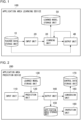
- FIG. 1 is a configuration diagram of an application area learning device 100 according to the present embodiment.
- the application area learning device 100 includes a teacher data storage unit 10, an input unit 20, a learning unit 30, an output unit 40, and a learned model storage unit 50.
- FIG. 1 is a block diagram featuring the functions, and these functional blocks may be implemented in a variety of forms by hardware, software, or a combination thereof.
- the teacher data storage unit 10 stores, as teacher data, a pair of a feature value within a contour extracted from an outline image of a shoe component and an adhesive application area in the shoe component.
- the shoe component may be, as an example, a shoe upper, and the outline image is an image obtained by capturing an image of the application surface of the upper from a normal direction of the application surface or from a direction that makes a predetermined angle to the normal direction of the application surface.
- the outline image is an image obtained by capturing an image of the application surface of the upper from a normal direction of the application surface or from a direction that makes a predetermined angle to the normal direction of the application surface.
- an adhesive is applied not only to the bottom surface of the upper but also to the side surfaces thereof; accordingly, it is desirable to use, as the outline image, an image captured from an oblique direction that makes a predetermined angle to the normal direction of the bottom surface.
- the "feature value within a contour extracted from an outline image” as used herein includes a feature value at least inside a contour extracted from an outline image and may also include, in addition thereto, a feature value of the contour itself.
- the feature values within a contour extracted from an outline image include, for example, edge data indicating a change of a predetermined threshold or greater in the luminance value between adjacent pixels within the contour, height data of a pixel within the contour, or both.
- the height data of a pixel within the contour as used herein is height information of a point corresponding to the pixel within the contour but is not essential information as a feature value within the contour.
- the feature values within a contour extracted from an outline image may further include, in addition thereto, pixel values (such as the color value and grayscale value) of a pixel within the contour.
- the input unit 20 reads the teacher data of a feature value within a contour from the teacher data storage unit 10 and supplies the teacher data to the learning unit 30.
- the learning unit 30 performs machine learning on a correlation between a feature value within a contour extracted from an outline image of a shoe component and an adhesive application area in the shoe component so as to generate a prediction model for an application area.
- a multilayer neural network model is used.
- a feature value within a contour extracted from an outline image is input as an explanatory variable.
- an objective variable output data
- weights of connections between the layers of the neural network are learned by deep learning so that the error between the application area data of the correct answer data and the output data output from the output layer is minimized.
- the learning unit 30 inputs the feature value within the contour supplied from the input unit 20 to the neural network and supplies prediction data of an application area output from the neural network to the output unit 40.
- the output unit 40 reads the teacher data of an adhesive application area from the teacher data storage unit 10. The output unit 40 then supplies, to the learning unit 30, the error between the teacher data of the application area and the prediction data of the application area output from the learning unit 30.
- the learning unit 30 adjusts the weights of each layer of the neural network so that the error supplied from the output unit 40 is minimized.
- the learning unit 30 then stores, as the prediction model for an application area, the learned neural network by which the error with respect to a set of the feature value within the contour and the teacher data of the application area has been minimized, in the learned model storage unit 50.
- the prediction model stored in the learned model storage unit 50 is used as a prediction model for estimating an application area from a feature value within a contour extracted from an outline image of an unknown shoe component, in an application area prediction device 200 described later.
- FIG. 2 is a configuration diagram of the application area prediction device 200 according to the present embodiment.
- the application area prediction device 200 includes an input unit 110, a prediction unit 120, a learned model storage unit 130, an output unit 140, an application area storage unit 150, a conversion unit 160, a control data storage unit 170, and an inspection unit 180.
- FIG. 2 is a block diagram featuring the functions, and these functional blocks may be implemented in a variety of forms by hardware, software, or a combination thereof.
- the learned model storage unit 130 stores a prediction model generated by the application area learning device 100.
- the prediction model is generated by performing machine learning on a correlation between a feature value within a contour extracted from an outline image of a shoe component and an adhesive application area in the shoe component, and an example of the prediction model is a learned multilayer neural network model.
- the input unit 110 provides, as input data, a feature value within a contour extracted from an outline image of an unknown shoe component, to the prediction unit 120.
- the prediction unit 120 predicts an application area from the input feature value within the contour extracted from the outline image of the shoe component and provides the application area to the output unit 140.
- the feature value within the contour extracted from the outline image is provided as the input data to a learned multilayer neural network model, and information indicating an application area is obtained as the output data.
- the output unit 140 stores the application area information predicted by the prediction unit 120 in the application area storage unit 150 and also provides the application area information to the conversion unit 160.
- the conversion unit 160 adds height data of the application surface of the shoe component to the two-dimensional coordinate data of pixels representing the respective points in the predicted application area, so as to generate three-dimensional coordinate data of each point in the application area. Based on the three-dimensional coordinate data of the application area, the conversion unit 160 also generates data used to control a robot arm for applying an adhesive to the application area and stores the data in the control data storage unit 170.
- the control data includes application trajectory data that indicates the trajectory of the robot arm moving to apply the adhesive to the application area.
- the application trajectories include a trajectory of circling the contour of the application area before moving within the application area, and a trajectory of moving in a zigzag pattern in the application area.
- the inspection unit 180 reads the predicted application area from the application area storage unit 150 and compares an actual application area applied by the robot arm or the like with the predicted application area to judge whether or not the adhesive has been applied appropriately. By comparing a captured image of the actual application area and the predicted application area, whether the actual applied area extends out beyond or falls short of the predicted application area is judged. Also for such judgement on appropriate application, machine learning may be used.
- FIGS. 3A-3C are diagrams that each show a feature value within a contour extracted from an outline image of a shoe component.
- a shoe upper as an example of the shoe component will be described.
- a shoe includes an upper and a sole as components.
- the sole has an almost definite shape, whereas the upper is generally rounded and curved and may have an indefinite shape due to molding errors and deformation, and hence, individual differences are likely to appear.
- FIG. 3A is an outline image of an upper captured from the direction facing the application surface, i.e., from the back side of the shoe.
- the feature value within the contour extracted from the outline image of the upper is a pixel value (such as the color value or grayscale value) of a pixel within the contour.
- FIG. 3B is an image obtained by extracting edges that each indicate a change of a predetermined threshold or greater in the luminance value between adjacent pixels in the outline image of FIG. 3A .
- the feature value within the contour extracted from the outline image of the upper is edge data indicating a change of a predetermined threshold or greater in the luminance value between adjacent pixels within the contour.
- FIG. 3C is an image that shows contour lines within the contour in the outline image of FIG. 3A .
- a contour line as used herein is a line that connects pixels of the same height within the contour.
- the feature value within the contour extracted from the outline image of the upper is height data of a pixel within the contour.
- the height data may be a depth image that contains the depth value of each pixel within the contour.
- the feature value within a contour extracted from an outline image to be provided as teacher data to the learning unit 30 of the application area learning device 100 shown in FIG. 1 is the edge data within the contour as shown in FIG. 3B or the height data of pixels within the contour as shown in FIG. 3C .
- the teacher data the color values or grayscale values of pixels within the contour as shown in FIG. 3A may be further provided to the learning unit 30.
- FIG. 4 is a diagram that shows an adhesive application area in the shoe component.
- a diagonally shaded area denoted by the reference sign 310 is an application area where an adhesive should be applied in the upper.
- an outline 300 of the upper partially extends out of the application area 310.
- the application area 310 is not flat but is curved at the arch such as to conform to the shape of a foot.
- the application area 310 in which the robot arm should move is defined not only by the two-dimensional coordinates but also by the three-dimensional coordinates including height.
- the application area 310 may be created and provided by a skilled processor of shoe components, for example, with respect to the outline 300 of a certain shoe component, based on his or her experience and know-how.
- the application area 310 is shown as a general image with color information. However, in the application area information used as teacher data, the color information may be ignored, and data indicating whether or not it is within the application area with 0 or 1 may also be used. Also, the application area information may be provided in the form of a point cloud, which is a set of points representing the application area in a two-dimensional coordinate system. The application area information is used as teacher data that indicates the correct answer of output data in the learning unit 30 of the application area learning device 100 shown in FIG. 1 .
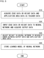
- FIG. 5 is a flowchart that shows a procedure of learning a prediction model for an application area, performed by the application area learning device 100 shown in FIG. 1 .
- the input unit 20 of the application area learning device 100 acquires, as teacher data, edge data or height data of pixels within a contour extracted from an outline image of a shoe component, and the output unit 40 acquires application area data as teacher data (S10).
- the learning unit 30 inputs, to a neural network, the edge data or height data acquired from the input unit 20 and acquires output data (S20).
- the output unit 40 feeds back, to the learning unit 30, an error between the output data acquired from the learning unit 30 and the application area data acquired as correct answer teacher data, and the learning unit 30 adjusts a parameter, such as a weight in the neural network, to minimize the error (S30).
- the learning unit 30 stores the learned model of the neural network in the learned model storage unit 50 (S40) .
- FIG. 6 is a flowchart that shows a procedure of prediction and judgment of an application area performed by the application area prediction device 200 shown in FIG. 2 .
- the input unit 110 of the application area prediction device 200 acquires edge data or height data of pixels within a contour extracted from an outline image of a shoe component (S50) .
- the prediction unit 120 inputs the edge data or height data acquired from the input unit 110 to a learned model of a neural network and predicts application area data (S20).
- the conversion unit 160 generates control data indicating an application trajectory of a robot arm based on the predicted application area data (S70).
- the robot arm is moved and controlled to apply an adhesive to the application area (S80).
- the inspection unit 180 compares the predicted application area and the actual application area to judge whether or not the adhesive has been applied appropriately (S90).
- the prediction accuracy has been evaluated by comparing the correct application area and the predicted application area.
- the prediction accuracy was evaluated by calculating an error rate by dividing the sum of the area of the portion of the predicted application area that extends out of the correct application area and the area by which the predicted application area falls short of the correct application area, by the area of the correct application area.
- the prediction accuracy was further improved, compared to the case where the edge data or height data was used as teacher data. Further, the prediction accuracy is expected to be improved when the edge data and height data are used in combination as teacher data, compared to the case where only one of the edge data or height data is used as teacher data.
- a highly accurate learned model for predicting the application area can be generated by machine learning using the edge data or height data extracted from an image of a shoe component and the application area as teacher data.
- the application area prediction device 200 of the present embodiment the application area can be predicted with high accuracy by extracting the edge data or height data from an image of a shoe component to be processed and inputting the edge data or height data to a generated learned model. Accordingly, the "marking out" process can be omitted, enabling automation of the visual judgment.
- the application area can be learned and predicted not only for shoe parts having definite shapes for which feature points can be set easily, such as soles, but also in consideration of a variety of shoe parts having indefinite shapes for which feature points cannot be set easily, such as uppers.
- the application area in an upper which is ambiguous and of which boundaries are difficult to determine by means of image recognition, can be extracted with high accuracy.
- the time required for shoe production can be reduced, and the processing quality can be improved.
- a feature value within a contour is extracted from an outline image of a shoe component in the description above, a feature value within a contour may be extracted from three-dimensional data of a shoe component.
- the present invention is applicable to a technology for learning and predicting an application area.
Landscapes
- Engineering & Computer Science (AREA)
- Theoretical Computer Science (AREA)
- Physics & Mathematics (AREA)
- General Physics & Mathematics (AREA)
- Multimedia (AREA)
- Computer Vision & Pattern Recognition (AREA)
- Evolutionary Computation (AREA)
- Artificial Intelligence (AREA)
- General Health & Medical Sciences (AREA)
- Health & Medical Sciences (AREA)
- Computing Systems (AREA)
- Software Systems (AREA)
- Databases & Information Systems (AREA)
- Medical Informatics (AREA)
- Biomedical Technology (AREA)
- Mathematical Physics (AREA)
- General Engineering & Computer Science (AREA)
- Molecular Biology (AREA)
- Data Mining & Analysis (AREA)
- Computational Linguistics (AREA)
- Biophysics (AREA)
- Life Sciences & Earth Sciences (AREA)
- Image Analysis (AREA)
Abstract
Description
- The present invention relates to a technology for learning an application area and a technology for predicting an application area.
- In the manufacturing process of workpieces, such as shoes, an area to be processed needs to be accurately recognized. Accordingly, a worker visually determines the area to be processed or performs "marking out" of drawing lines on the surface of the material. Such work requires workforce, which hinders labor savings in the production process and makes it difficult to introduce automated production using industrial robots.
- For example, in the process of attaching a sole to an upper of a shoe, a worker determines an area in the upper where an adhesive is to be applied and moves a robot arm to the application area to apply the adhesive.
- Patent Literature 1 discloses an adhesive application system for shoes, in which the outline of the shadow of a shoe component illuminated by a backlight is recognized, an application trajectory for application of an adhesive to the bottom surface of the shoe component is set on the basis of the outline, and a movement mechanism is controlled such that an adhesive application part moves along the application trajectory, so that the adhesive application part applies the adhesive to the bottom surface of the shoe component.
- Patent Literature 1:
Japanese Patent No. 6014786 - In the conventional method of recognizing the outline of a workpiece based on three-dimensional information or captured images thereof to determine the area to be processed, there has been a problem that the recognition with high accuracy in consideration of a variety of workpieces is difficult.
- The present disclosure has been made in view of such a problem, and a purpose thereof is to provide a technology for learning and predicting an application area with high accuracy.
- To solve the problem above, an application area learning device according to one aspect of the present invention includes a learning unit that performs machine learning on a correlation between a feature value at least inside a contour extracted from an outline image of a shoe component and an application area of an adhesive in the shoe component and generates a prediction model, and a learned model storage unit that stores the prediction model.
- Another aspect of the present invention relates to an application area prediction device. The device includes a learned model storage unit that stores a prediction model generated by performing machine learning on a correlation between a feature value at least inside a contour extracted from an outline image of a shoe component and an application area of an adhesive in the shoe component, and a prediction unit that predicts, based on the prediction model, an application area from a feature value at least inside a contour extracted from an outline image of a shoe component and outputs the application area.
- Yet another aspect of the present invention relates to an application area learning method. In the method, a computer performs machine learning on a correlation between a feature value at least inside a contour extracted from an outline image of a shoe component and an application area of an adhesive in the shoe component and generates a prediction model.
- Still yet another aspect of the present invention relates to an application area prediction method. In the method, based on a prediction model generated by performing machine learning on a correlation between a feature value at least inside a contour extracted from an outline image of a shoe component and an application area of an adhesive in the shoe component, a computer predicts an application area from a feature value at least inside a contour extracted from an outline image of a shoe component and outputs the application area.
- Optional combinations of the aforementioned constituting elements, and implementation of the present invention in the form of methods, apparatuses, systems, computer programs, data structures, and recording media may also be practiced as additional modes of the present invention.
- The present invention enables learning and prediction of an application area with high accuracy.
-
-
FIG. 1 is a configuration diagram of an application area learning device according to the present embodiment. -
FIG. 2 is a configuration diagram of an application area prediction device according to the present embodiment. -
FIGS. 3A-3C are diagrams that each show a feature value within a contour extracted from an outline image of a shoe component. -
FIG. 4 is a diagram that shows an adhesive application area in the shoe component. -
FIG. 5 is a flowchart that shows a procedure of learning a prediction model for an application area, performed by the application area learning device shown inFIG. 1 . -
FIG. 6 is a flowchart that shows a procedure of prediction and judgment of an application area, performed by the application area prediction device shown inFIG. 2 . -
FIG. 1 is a configuration diagram of an applicationarea learning device 100 according to the present embodiment. The applicationarea learning device 100 includes a teacherdata storage unit 10, aninput unit 20, alearning unit 30, anoutput unit 40, and a learnedmodel storage unit 50.FIG. 1 is a block diagram featuring the functions, and these functional blocks may be implemented in a variety of forms by hardware, software, or a combination thereof. - The teacher
data storage unit 10 stores, as teacher data, a pair of a feature value within a contour extracted from an outline image of a shoe component and an adhesive application area in the shoe component. - The shoe component may be, as an example, a shoe upper, and the outline image is an image obtained by capturing an image of the application surface of the upper from a normal direction of the application surface or from a direction that makes a predetermined angle to the normal direction of the application surface. Especially, in the case of shoes with cup soles, such as running shoes, an adhesive is applied not only to the bottom surface of the upper but also to the side surfaces thereof; accordingly, it is desirable to use, as the outline image, an image captured from an oblique direction that makes a predetermined angle to the normal direction of the bottom surface.
- The "feature value within a contour extracted from an outline image" as used herein includes a feature value at least inside a contour extracted from an outline image and may also include, in addition thereto, a feature value of the contour itself.
- The feature values within a contour extracted from an outline image include, for example, edge data indicating a change of a predetermined threshold or greater in the luminance value between adjacent pixels within the contour, height data of a pixel within the contour, or both. The height data of a pixel within the contour as used herein is height information of a point corresponding to the pixel within the contour but is not essential information as a feature value within the contour. The feature values within a contour extracted from an outline image may further include, in addition thereto, pixel values (such as the color value and grayscale value) of a pixel within the contour.
- The
input unit 20 reads the teacher data of a feature value within a contour from the teacherdata storage unit 10 and supplies the teacher data to thelearning unit 30. - The
learning unit 30 performs machine learning on a correlation between a feature value within a contour extracted from an outline image of a shoe component and an adhesive application area in the shoe component so as to generate a prediction model for an application area. - As an example of machine learning, a multilayer neural network model is used. Into the input layer of a multilayer neural network model, a feature value within a contour extracted from an outline image is input as an explanatory variable. From the output layer of the multilayer neural network model, an objective variable (output data) indicating whether or not it is an application area is output. Accordingly, weights of connections between the layers of the neural network are learned by deep learning so that the error between the application area data of the correct answer data and the output data output from the output layer is minimized.
- The
learning unit 30 inputs the feature value within the contour supplied from theinput unit 20 to the neural network and supplies prediction data of an application area output from the neural network to theoutput unit 40. - The
output unit 40 reads the teacher data of an adhesive application area from the teacherdata storage unit 10. Theoutput unit 40 then supplies, to thelearning unit 30, the error between the teacher data of the application area and the prediction data of the application area output from thelearning unit 30. - The
learning unit 30 adjusts the weights of each layer of the neural network so that the error supplied from theoutput unit 40 is minimized. Thelearning unit 30 then stores, as the prediction model for an application area, the learned neural network by which the error with respect to a set of the feature value within the contour and the teacher data of the application area has been minimized, in the learnedmodel storage unit 50. - The prediction model stored in the learned
model storage unit 50 is used as a prediction model for estimating an application area from a feature value within a contour extracted from an outline image of an unknown shoe component, in an applicationarea prediction device 200 described later. -
FIG. 2 is a configuration diagram of the applicationarea prediction device 200 according to the present embodiment. The applicationarea prediction device 200 includes aninput unit 110, aprediction unit 120, a learnedmodel storage unit 130, anoutput unit 140, an applicationarea storage unit 150, aconversion unit 160, a controldata storage unit 170, and aninspection unit 180.FIG. 2 is a block diagram featuring the functions, and these functional blocks may be implemented in a variety of forms by hardware, software, or a combination thereof. - The learned
model storage unit 130 stores a prediction model generated by the applicationarea learning device 100. The prediction model is generated by performing machine learning on a correlation between a feature value within a contour extracted from an outline image of a shoe component and an adhesive application area in the shoe component, and an example of the prediction model is a learned multilayer neural network model. - The
input unit 110 provides, as input data, a feature value within a contour extracted from an outline image of an unknown shoe component, to theprediction unit 120. - Based on the prediction model stored in the learned
model storage unit 130, theprediction unit 120 predicts an application area from the input feature value within the contour extracted from the outline image of the shoe component and provides the application area to theoutput unit 140. In specific, the feature value within the contour extracted from the outline image is provided as the input data to a learned multilayer neural network model, and information indicating an application area is obtained as the output data. - The
output unit 140 stores the application area information predicted by theprediction unit 120 in the applicationarea storage unit 150 and also provides the application area information to theconversion unit 160. - The
conversion unit 160 adds height data of the application surface of the shoe component to the two-dimensional coordinate data of pixels representing the respective points in the predicted application area, so as to generate three-dimensional coordinate data of each point in the application area. Based on the three-dimensional coordinate data of the application area, theconversion unit 160 also generates data used to control a robot arm for applying an adhesive to the application area and stores the data in the controldata storage unit 170. The control data includes application trajectory data that indicates the trajectory of the robot arm moving to apply the adhesive to the application area. The application trajectories include a trajectory of circling the contour of the application area before moving within the application area, and a trajectory of moving in a zigzag pattern in the application area. - The
inspection unit 180 reads the predicted application area from the applicationarea storage unit 150 and compares an actual application area applied by the robot arm or the like with the predicted application area to judge whether or not the adhesive has been applied appropriately. By comparing a captured image of the actual application area and the predicted application area, whether the actual applied area extends out beyond or falls short of the predicted application area is judged. Also for such judgement on appropriate application, machine learning may be used. -
FIGS. 3A-3C are diagrams that each show a feature value within a contour extracted from an outline image of a shoe component. Here, the case of using a shoe upper as an example of the shoe component will be described. - A shoe includes an upper and a sole as components. The sole has an almost definite shape, whereas the upper is generally rounded and curved and may have an indefinite shape due to molding errors and deformation, and hence, individual differences are likely to appear.
-
FIG. 3A is an outline image of an upper captured from the direction facing the application surface, i.e., from the back side of the shoe. In this case, the feature value within the contour extracted from the outline image of the upper is a pixel value (such as the color value or grayscale value) of a pixel within the contour. -
FIG. 3B is an image obtained by extracting edges that each indicate a change of a predetermined threshold or greater in the luminance value between adjacent pixels in the outline image ofFIG. 3A . In this case, the feature value within the contour extracted from the outline image of the upper is edge data indicating a change of a predetermined threshold or greater in the luminance value between adjacent pixels within the contour. -
FIG. 3C is an image that shows contour lines within the contour in the outline image ofFIG. 3A . A contour line as used herein is a line that connects pixels of the same height within the contour. In this case, the feature value within the contour extracted from the outline image of the upper is height data of a pixel within the contour. Besides the contour line image within the contour as shown inFIG. 3C , the height data may be a depth image that contains the depth value of each pixel within the contour. - The feature value within a contour extracted from an outline image to be provided as teacher data to the
learning unit 30 of the applicationarea learning device 100 shown inFIG. 1 is the edge data within the contour as shown inFIG. 3B or the height data of pixels within the contour as shown inFIG. 3C . As the teacher data, the color values or grayscale values of pixels within the contour as shown inFIG. 3A may be further provided to thelearning unit 30. -
FIG. 4 is a diagram that shows an adhesive application area in the shoe component. In the image of the bottom surface of the upper similar toFIG. 3A , a diagonally shaded area denoted by thereference sign 310 is an application area where an adhesive should be applied in the upper. It should be noted that, since the upper is rounded, anoutline 300 of the upper partially extends out of theapplication area 310. It should also be noted that theapplication area 310 is not flat but is curved at the arch such as to conform to the shape of a foot. In other words, theapplication area 310 in which the robot arm should move is defined not only by the two-dimensional coordinates but also by the three-dimensional coordinates including height. - The
application area 310 may be created and provided by a skilled processor of shoe components, for example, with respect to theoutline 300 of a certain shoe component, based on his or her experience and know-how. - In
FIG. 4 , theapplication area 310 is shown as a general image with color information. However, in the application area information used as teacher data, the color information may be ignored, and data indicating whether or not it is within the application area with 0 or 1 may also be used. Also, the application area information may be provided in the form of a point cloud, which is a set of points representing the application area in a two-dimensional coordinate system. The application area information is used as teacher data that indicates the correct answer of output data in thelearning unit 30 of the applicationarea learning device 100 shown inFIG. 1 . -
FIG. 5 is a flowchart that shows a procedure of learning a prediction model for an application area, performed by the applicationarea learning device 100 shown inFIG. 1 . - The
input unit 20 of the applicationarea learning device 100 acquires, as teacher data, edge data or height data of pixels within a contour extracted from an outline image of a shoe component, and theoutput unit 40 acquires application area data as teacher data (S10). - The
learning unit 30 inputs, to a neural network, the edge data or height data acquired from theinput unit 20 and acquires output data (S20). - The
output unit 40 feeds back, to thelearning unit 30, an error between the output data acquired from thelearning unit 30 and the application area data acquired as correct answer teacher data, and thelearning unit 30 adjusts a parameter, such as a weight in the neural network, to minimize the error (S30). - The
learning unit 30 stores the learned model of the neural network in the learned model storage unit 50 (S40) . -
FIG. 6 is a flowchart that shows a procedure of prediction and judgment of an application area performed by the applicationarea prediction device 200 shown inFIG. 2 . - The
input unit 110 of the applicationarea prediction device 200 acquires edge data or height data of pixels within a contour extracted from an outline image of a shoe component (S50) . - The
prediction unit 120 inputs the edge data or height data acquired from theinput unit 110 to a learned model of a neural network and predicts application area data (S20). - The
conversion unit 160 generates control data indicating an application trajectory of a robot arm based on the predicted application area data (S70). - Based on the control data indicating the application trajectory, the robot arm is moved and controlled to apply an adhesive to the application area (S80).
- The
inspection unit 180 compares the predicted application area and the actual application area to judge whether or not the adhesive has been applied appropriately (S90). - Through experiments, the prediction accuracy has been evaluated by comparing the correct application area and the predicted application area. The prediction accuracy was evaluated by calculating an error rate by dividing the sum of the area of the portion of the predicted application area that extends out of the correct application area and the area by which the predicted application area falls short of the correct application area, by the area of the correct application area.
- As a result, sufficient prediction accuracy was confirmed when only the pixel values (such as the color values or grayscale values) of pixels within the contour of an outline image were used as teacher data to learn the application area or when the edge data or height data were used as teacher data to learn the application area. In particular, using the edge data as teacher data contributes to improvement of the prediction accuracy.
- Also, when the edge data or height data and the pixel values (such as the color values or grayscale values) of pixels within the contour were used in combination as teacher data, the prediction accuracy was further improved, compared to the case where the edge data or height data was used as teacher data. Further, the prediction accuracy is expected to be improved when the edge data and height data are used in combination as teacher data, compared to the case where only one of the edge data or height data is used as teacher data.
- As described above, with the application
area learning device 100 of the present embodiment, a highly accurate learned model for predicting the application area can be generated by machine learning using the edge data or height data extracted from an image of a shoe component and the application area as teacher data. Also, with the applicationarea prediction device 200 of the present embodiment, the application area can be predicted with high accuracy by extracting the edge data or height data from an image of a shoe component to be processed and inputting the edge data or height data to a generated learned model. Accordingly, the "marking out" process can be omitted, enabling automation of the visual judgment. - In particular, the application area can be learned and predicted not only for shoe parts having definite shapes for which feature points can be set easily, such as soles, but also in consideration of a variety of shoe parts having indefinite shapes for which feature points cannot be set easily, such as uppers. The application area in an upper, which is ambiguous and of which boundaries are difficult to determine by means of image recognition, can be extracted with high accuracy. By increasing the learning data, a variety of shoes can be dealt with, so that the versatility can be improved.
- Also, by automatically generating the control data for the robot arm based on a predicted application area, the time required for shoe production can be reduced, and the processing quality can be improved.
- The present invention has been described with reference to an embodiment. The embodiment is intended to be illustrative only, and it will be obvious to those skilled in the art that various modifications to a combination of constituting elements or processes could be developed and that such modifications also fall within the scope of the present invention.
- Although a feature value within a contour is extracted from an outline image of a shoe component in the description above, a feature value within a contour may be extracted from three-dimensional data of a shoe component.
- The present invention is applicable to a technology for learning and predicting an application area.
-
- 10
- teacher data storage unit
- 20
- input unit
- 30
- learning unit
- 40
- output unit
- 50
- learned model storage unit
- 100
- application area learning device
- 110
- input unit
- 120
- prediction unit
- 130
- learned model storage unit
- 140
- output unit
- 150
- application area storage unit
- 160
- conversion unit
- 170
- control data storage unit
- 180
- inspection unit
- 200
- application area prediction device
Claims (12)
- An application area learning device, comprising:a learning unit that performs machine learning on a correlation between a feature value at least inside a contour extracted from an outline image of a shoe component and an application area of an adhesive in the shoe component and generates a prediction model; anda learned model storage unit that stores the prediction model.
- The application area learning device according to claim 1, wherein the feature value at least inside the contour extracted from the outline image includes edge data indicating a change of a predetermined threshold or greater in the luminance value between adjacent pixels at least inside the contour.
- The application area learning device according to claim 1 or 2, wherein the feature value at least inside the contour extracted from the outline image includes height data of a pixel at least inside the contour.
- The application area learning device according to claim 2 or 3, wherein the feature value at least inside the contour extracted from the outline image further includes a color value or a grayscale value of a pixel at least inside the contour.
- The application area learning device according to any one of claims 1 through 4, wherein the shoe component is an upper of a shoe, and the outline image is an image obtained by capturing an image of an application surface of the upper from a normal direction of the application surface or from a direction that makes a predetermined angle to the normal direction of the application surface.
- An application area prediction device, comprising:a learned model storage unit that stores a prediction model generated by performing machine learning on a correlation between a feature value at least inside a contour extracted from an outline image of a shoe component and an application area of an adhesive in the shoe component; anda prediction unit that predicts, based on the prediction model, an application area from a feature value at least inside a contour extracted from an outline image of a shoe component and outputs the application area.
- The application area prediction device according to claim 6, further comprising a conversion unit that generates control data indicating an application trajectory in a predicted application area.
- The application area prediction device according to claim 6 or 7, further comprising an inspection unit that compares an actual application area with a predicted application area to judge appropriateness.
- An application area learning method in which a computer performs machine learning on a correlation between a feature value at least inside a contour extracted from an outline image of a shoe component and an application area of an adhesive in the shoe component and generates a prediction model.
- An application area prediction method in which, based on a prediction model generated by performing machine learning on a correlation between a feature value at least inside a contour extracted from an outline image of a shoe component and an application area of an adhesive in the shoe component, a computer predicts an application area from a feature value at least inside a contour extracted from an outline image of a shoe component and outputs the application area.
- An application area learning program causing a computer to perform machine learning on a correlation between a feature value at least inside a contour extracted from an outline image of a shoe component and an application area of an adhesive in the shoe component and generate a prediction model.
- An application area prediction program causing a computer to predict, based on a prediction model generated by performing machine learning on a correlation between a feature value at least inside a contour extracted from an outline image of a shoe component and an application area of an adhesive in the shoe component, an application area from a feature value at least inside a contour extracted from an outline image of a shoe component and to output the application area.
Applications Claiming Priority (1)
| Application Number | Priority Date | Filing Date | Title |
|---|---|---|---|
| PCT/JP2020/040234 WO2022091212A1 (en) | 2020-10-27 | 2020-10-27 | Coating region learning device, coating region learning method, coating region prediction device, and coating region prediction method |
Publications (2)
| Publication Number | Publication Date |
|---|---|
| EP4201247A1 true EP4201247A1 (en) | 2023-06-28 |
| EP4201247A4 EP4201247A4 (en) | 2023-10-25 |
Family
ID=81382226
Family Applications (1)
| Application Number | Title | Priority Date | Filing Date |
|---|---|---|---|
| EP20959730.1A Pending EP4201247A4 (en) | 2020-10-27 | 2020-10-27 | Coating region learning device, coating region learning method, coating region prediction device, and coating region prediction method |
Country Status (5)
| Country | Link |
|---|---|
| US (1) | US12469251B2 (en) |
| EP (1) | EP4201247A4 (en) |
| JP (1) | JPWO2022091212A1 (en) |
| CN (1) | CN116322419A (en) |
| WO (1) | WO2022091212A1 (en) |
Families Citing this family (1)
| Publication number | Priority date | Publication date | Assignee | Title |
|---|---|---|---|---|
| WO2025134435A1 (en) * | 2023-12-22 | 2025-06-26 | 株式会社アシックス | Shoe processing assistance method, shoe processing assistance device, and shoe processing assistance program |
Family Cites Families (6)
| Publication number | Priority date | Publication date | Assignee | Title |
|---|---|---|---|---|
| US8849620B2 (en) * | 2011-11-18 | 2014-09-30 | Nike, Inc. | Automated 3-D modeling of shoe parts |
| CN108135331A (en) * | 2015-09-03 | 2018-06-08 | 株式会社安川电机 | Adhesive coating system for shoes, coating trajectory generating device, and shoe manufacturing method |
| JP7039991B2 (en) * | 2017-12-22 | 2022-03-23 | カシオ計算機株式会社 | Contour detection device, drawing device, contour detection method and contour detection program |
| JP7299002B2 (en) * | 2018-08-23 | 2023-06-27 | ファナック株式会社 | Discriminator and machine learning method |
| WO2020183621A1 (en) * | 2019-03-12 | 2020-09-17 | カワノ株式会社 | Adhesive coating device and adhesive coating method |
| CN110710759A (en) * | 2019-09-09 | 2020-01-21 | 丁金波 | Sole spouts gluey system based on 3D scanning and vision are rectified |
-
2020
- 2020-10-27 EP EP20959730.1A patent/EP4201247A4/en active Pending
- 2020-10-27 US US18/029,877 patent/US12469251B2/en active Active
- 2020-10-27 JP JP2022558639A patent/JPWO2022091212A1/ja active Pending
- 2020-10-27 CN CN202080105754.7A patent/CN116322419A/en active Pending
- 2020-10-27 WO PCT/JP2020/040234 patent/WO2022091212A1/en not_active Ceased
Also Published As
| Publication number | Publication date |
|---|---|
| EP4201247A4 (en) | 2023-10-25 |
| US20230274524A1 (en) | 2023-08-31 |
| CN116322419A (en) | 2023-06-23 |
| US12469251B2 (en) | 2025-11-11 |
| JPWO2022091212A1 (en) | 2022-05-05 |
| WO2022091212A1 (en) | 2022-05-05 |
Similar Documents
| Publication | Publication Date | Title |
|---|---|---|
| JP6542824B2 (en) | Image processing apparatus and image processing method for calculating likelihood of image of object detected from input image | |
| Prezas et al. | AI-enhanced vision system for dispensing process monitoring and quality control in manufacturing of large parts | |
| US10960550B2 (en) | Identification code reading apparatus and machine learning device | |
| JP2021030407A (en) | Information processing equipment, information processing methods and programs | |
| CN112775959A (en) | Method and system for determining grabbing pose of manipulator and storage medium | |
| KR102452315B1 (en) | Apparatus and method of robot control through vision recognition using deep learning and marker | |
| CN121018601B (en) | Picking mechanical arm operation method and system based on visual feedback | |
| CN114794665B (en) | Method, device, system, and computer-readable storage medium for gluing shoe uppers | |
| US11865730B2 (en) | Camera position/attitude calibration device, camera position/attitude calibration method, and robot | |
| CN118809624B (en) | Mechanical arm sorting and grabbing control method, system and device | |
| KR20190113140A (en) | Auto picking system and method for automatically picking using the same | |
| JP2017111638A (en) | Image processing method, image processing apparatus, image processing system, production apparatus, program, and recording medium | |
| CN113269008A (en) | Pedestrian trajectory prediction method and device, electronic equipment and storage medium | |
| CN112805127A (en) | Method and apparatus for creating robot control program | |
| JP7432427B2 (en) | Application trajectory prediction device and application trajectory prediction method, and application trajectory learning device and application trajectory learning method | |
| US12469251B2 (en) | Coating region learning device, coating region learning method, coating region prediction device, and coating region prediction method | |
| CN118829511A (en) | Robotic system and method for installing component assemblies | |
| CN110942083A (en) | Imaging device and imaging system | |
| US12350847B2 (en) | Method for controlling a robot for manipulating, in particular picking up, an object | |
| KR20040100963A (en) | Image processing apparatus | |
| CN119927930B (en) | A method, system and medium for intelligent control of a robotic arm based on machine vision | |
| CN115972191A (en) | Two-armed robot taught from two-handed human demonstration | |
| JP7383999B2 (en) | Collaborative work system, analysis device and analysis program | |
| Zogopoulos et al. | Image-based state tracking in augmented reality supported assembly operations | |
| Tafuro et al. | Towards intelligent robotic sole deburring: from burrs identification to path planning |
Legal Events
| Date | Code | Title | Description |
|---|---|---|---|
| STAA | Information on the status of an ep patent application or granted ep patent |
Free format text: STATUS: THE INTERNATIONAL PUBLICATION HAS BEEN MADE |
|
| PUAI | Public reference made under article 153(3) epc to a published international application that has entered the european phase |
Free format text: ORIGINAL CODE: 0009012 |
|
| STAA | Information on the status of an ep patent application or granted ep patent |
Free format text: STATUS: REQUEST FOR EXAMINATION WAS MADE |
|
| 17P | Request for examination filed |
Effective date: 20230320 |
|
| AK | Designated contracting states |
Kind code of ref document: A1 Designated state(s): AL AT BE BG CH CY CZ DE DK EE ES FI FR GB GR HR HU IE IS IT LI LT LU LV MC MK MT NL NO PL PT RO RS SE SI SK SM TR |
|
| A4 | Supplementary search report drawn up and despatched |
Effective date: 20230927 |
|
| RIC1 | Information provided on ipc code assigned before grant |
Ipc: G06N 3/02 20060101ALI20230921BHEP Ipc: A43D 25/18 20060101AFI20230921BHEP |
|
| DAV | Request for validation of the european patent (deleted) | ||
| DAX | Request for extension of the european patent (deleted) |