EP4201178A1 - System and method for generating swath lines for a work vehicle - Google Patents
System and method for generating swath lines for a work vehicle Download PDFInfo
- Publication number
- EP4201178A1 EP4201178A1 EP22213067.6A EP22213067A EP4201178A1 EP 4201178 A1 EP4201178 A1 EP 4201178A1 EP 22213067 A EP22213067 A EP 22213067A EP 4201178 A1 EP4201178 A1 EP 4201178A1
- Authority
- EP
- European Patent Office
- Prior art keywords
- work vehicle
- line
- computing system
- swath
- continuous
- Prior art date
- Legal status (The legal status is an assumption and is not a legal conclusion. Google has not performed a legal analysis and makes no representation as to the accuracy of the status listed.)
- Withdrawn
Links
Images


Classifications
-
- B—PERFORMING OPERATIONS; TRANSPORTING
- B60—VEHICLES IN GENERAL
- B60R—VEHICLES, VEHICLE FITTINGS, OR VEHICLE PARTS, NOT OTHERWISE PROVIDED FOR
- B60R16/00—Electric or fluid circuits specially adapted for vehicles and not otherwise provided for; Arrangement of elements of electric or fluid circuits specially adapted for vehicles and not otherwise provided for
- B60R16/02—Electric or fluid circuits specially adapted for vehicles and not otherwise provided for; Arrangement of elements of electric or fluid circuits specially adapted for vehicles and not otherwise provided for electric constitutive elements
- B60R16/023—Electric or fluid circuits specially adapted for vehicles and not otherwise provided for; Arrangement of elements of electric or fluid circuits specially adapted for vehicles and not otherwise provided for electric constitutive elements for transmission of signals between vehicle parts or subsystems
-
- A—HUMAN NECESSITIES
- A01—AGRICULTURE; FORESTRY; ANIMAL HUSBANDRY; HUNTING; TRAPPING; FISHING
- A01B—SOIL WORKING IN AGRICULTURE OR FORESTRY; PARTS, DETAILS, OR ACCESSORIES OF AGRICULTURAL MACHINES OR IMPLEMENTS, IN GENERAL
- A01B69/00—Steering of agricultural machines or implements; Guiding agricultural machines or implements on a desired track
- A01B69/007—Steering or guiding of agricultural vehicles, e.g. steering of the tractor to keep the plough in the furrow
- A01B69/008—Steering or guiding of agricultural vehicles, e.g. steering of the tractor to keep the plough in the furrow automatic
-
- A—HUMAN NECESSITIES
- A01—AGRICULTURE; FORESTRY; ANIMAL HUSBANDRY; HUNTING; TRAPPING; FISHING
- A01D—HARVESTING; MOWING
- A01D41/00—Combines, i.e. harvesters or mowers combined with threshing devices
- A01D41/12—Details of combines
- A01D41/127—Control or measuring arrangements specially adapted for combines
- A01D41/1278—Control or measuring arrangements specially adapted for combines for automatic steering
-
- B—PERFORMING OPERATIONS; TRANSPORTING
- B62—LAND VEHICLES FOR TRAVELLING OTHERWISE THAN ON RAILS
- B62D—MOTOR VEHICLES; TRAILERS
- B62D55/00—Endless track vehicles
- B62D55/06—Endless track vehicles with tracks without ground wheels
- B62D55/065—Multi-track vehicles, i.e. more than two tracks
-
- G—PHYSICS
- G01—MEASURING; TESTING
- G01B—MEASURING LENGTH, THICKNESS OR SIMILAR LINEAR DIMENSIONS; MEASURING ANGLES; MEASURING AREAS; MEASURING IRREGULARITIES OF SURFACES OR CONTOURS
- G01B21/00—Measuring arrangements or details thereof, where the measuring technique is not covered by the other groups of this subclass, unspecified or not relevant
-
- G—PHYSICS
- G01—MEASURING; TESTING
- G01S—RADIO DIRECTION-FINDING; RADIO NAVIGATION; DETERMINING DISTANCE OR VELOCITY BY USE OF RADIO WAVES; LOCATING OR PRESENCE-DETECTING BY USE OF THE REFLECTION OR RERADIATION OF RADIO WAVES; ANALOGOUS ARRANGEMENTS USING OTHER WAVES
- G01S19/00—Satellite radio beacon positioning systems; Determining position, velocity or attitude using signals transmitted by such systems
- G01S19/38—Determining a navigation solution using signals transmitted by a satellite radio beacon positioning system
- G01S19/39—Determining a navigation solution using signals transmitted by a satellite radio beacon positioning system the satellite radio beacon positioning system transmitting time-stamped messages, e.g. GPS [Global Positioning System], GLONASS [Global Orbiting Navigation Satellite System] or GALILEO
- G01S19/42—Determining position
-
- G—PHYSICS
- G05—CONTROLLING; REGULATING
- G05D—SYSTEMS FOR CONTROLLING OR REGULATING NON-ELECTRIC VARIABLES
- G05D1/00—Control of position, course, altitude or attitude of land, water, air or space vehicles, e.g. using automatic pilots
- G05D1/02—Control of position or course in two dimensions
- G05D1/021—Control of position or course in two dimensions specially adapted to land vehicles
- G05D1/0212—Control of position or course in two dimensions specially adapted to land vehicles with means for defining a desired trajectory
-
- G—PHYSICS
- G05—CONTROLLING; REGULATING
- G05D—SYSTEMS FOR CONTROLLING OR REGULATING NON-ELECTRIC VARIABLES
- G05D1/00—Control of position, course, altitude or attitude of land, water, air or space vehicles, e.g. using automatic pilots
- G05D1/02—Control of position or course in two dimensions
- G05D1/021—Control of position or course in two dimensions specially adapted to land vehicles
- G05D1/0212—Control of position or course in two dimensions specially adapted to land vehicles with means for defining a desired trajectory
- G05D1/0221—Control of position or course in two dimensions specially adapted to land vehicles with means for defining a desired trajectory involving a learning process
-
- G—PHYSICS
- G05—CONTROLLING; REGULATING
- G05D—SYSTEMS FOR CONTROLLING OR REGULATING NON-ELECTRIC VARIABLES
- G05D1/00—Control of position, course, altitude or attitude of land, water, air or space vehicles, e.g. using automatic pilots
- G05D1/02—Control of position or course in two dimensions
- G05D1/021—Control of position or course in two dimensions specially adapted to land vehicles
- G05D1/0276—Control of position or course in two dimensions specially adapted to land vehicles using signals provided by a source external to the vehicle
- G05D1/0278—Control of position or course in two dimensions specially adapted to land vehicles using signals provided by a source external to the vehicle using satellite positioning signals, e.g. GPS
-
- A—HUMAN NECESSITIES
- A01—AGRICULTURE; FORESTRY; ANIMAL HUSBANDRY; HUNTING; TRAPPING; FISHING
- A01B—SOIL WORKING IN AGRICULTURE OR FORESTRY; PARTS, DETAILS, OR ACCESSORIES OF AGRICULTURAL MACHINES OR IMPLEMENTS, IN GENERAL
- A01B76/00—Parts, details or accessories of agricultural machines or implements, not provided for in groups A01B51/00 - A01B75/00
-
- B—PERFORMING OPERATIONS; TRANSPORTING
- B60—VEHICLES IN GENERAL
- B60K—ARRANGEMENT OR MOUNTING OF PROPULSION UNITS OR OF TRANSMISSIONS IN VEHICLES; ARRANGEMENT OR MOUNTING OF PLURAL DIVERSE PRIME-MOVERS IN VEHICLES; AUXILIARY DRIVES FOR VEHICLES; INSTRUMENTATION OR DASHBOARDS FOR VEHICLES; ARRANGEMENTS IN CONNECTION WITH COOLING, AIR INTAKE, GAS EXHAUST OR FUEL SUPPLY OF PROPULSION UNITS IN VEHICLES
- B60K2360/00—Indexing scheme associated with groups B60K35/00 or B60K37/00 relating to details of instruments or dashboards
- B60K2360/16—Type of output information
- B60K2360/166—Navigation
-
- B—PERFORMING OPERATIONS; TRANSPORTING
- B60—VEHICLES IN GENERAL
- B60K—ARRANGEMENT OR MOUNTING OF PROPULSION UNITS OR OF TRANSMISSIONS IN VEHICLES; ARRANGEMENT OR MOUNTING OF PLURAL DIVERSE PRIME-MOVERS IN VEHICLES; AUXILIARY DRIVES FOR VEHICLES; INSTRUMENTATION OR DASHBOARDS FOR VEHICLES; ARRANGEMENTS IN CONNECTION WITH COOLING, AIR INTAKE, GAS EXHAUST OR FUEL SUPPLY OF PROPULSION UNITS IN VEHICLES
- B60K35/00—Instruments specially adapted for vehicles; Arrangement of instruments in or on vehicles
- B60K35/20—Output arrangements, i.e. from vehicle to user, associated with vehicle functions or specially adapted therefor
- B60K35/28—Output arrangements, i.e. from vehicle to user, associated with vehicle functions or specially adapted therefor characterised by the type of the output information, e.g. video entertainment or vehicle dynamics information; characterised by the purpose of the output information, e.g. for attracting the attention of the driver
Definitions
- the present disclosure generally relates to work vehicles and, more particularly, to systems and methods for generating swath lines for a work vehicle, such as an agricultural or construction vehicle.
- the present subject matter is directed to a work vehicle.
- the work vehicle includes a frame configured to support a plurality of components of the work vehicle.
- the work vehicle includes a location sensor configured to capture data indicative of a location of the work vehicle within a field.
- the work vehicle includes a computing system communicatively coupled to the location sensor.
- the computing system is configured to control an operation of the plurality of components as the work vehicle makes a first pass across the field.
- the computing system is configured to record a travel path of the work vehicle as the work vehicle make the first pass across the field based on data captured by the location sensor.
- the computing system is configured to generate a continuous swath line formed from a plurality of line segments such that the continuous swath line corresponds to the recorded travel path of the work vehicle.
- the present subject matter is directed to a system for generating swath lines for a work vehicle.
- the system includes a location sensor configured to capture data indicative of a location of the work vehicle within a field.
- the system includes a computing system communicatively coupled to the location sensor.
- the computing system is configured to control an operation of the work vehicle as the work vehicle makes a first pass across the field.
- the computing system is configured to record a travel path of the work vehicle as the work vehicle make the first pass across the field based on data captured by the location sensor.
- the computing system is configured to generate a continuous swath line formed from a plurality of line segments such that the continuous swath line corresponds to the recorded travel path of the work vehicle.
- the present subject matter is directed to a method for generating swath lines for a work vehicle.
- the work vehicle includes a location sensor configured to capture data indicative of a location of the work vehicle within a field.
- the method includes controlling, with a computing system, an operation of the work vehicle as the work vehicle makes a first pass across the field.
- the method includes recording, with the computing system, a travel path of the work vehicle across the field based on data captured by the location sensor.
- the method includes generating, with the computing system, a continuous swath line formed from a plurality of line segments such that the continuous swath line corresponds to the recorded travel path of the work vehicle.
- a computing system of the disclosed system is configured to control the operation of the work vehicle as the vehicle makes a first pass across the field.
- an operator may control the direction of travel of the work vehicle during the first pass.
- the computing system records the travel path of the vehicle based on data (e.g., coordinates) captured by a location sensor.
- the computing system generates a continuous swath line formed from a plurality of line segments such that the continuous swath line corresponds to the recorded travel path of the work vehicle.
- the line segments may include straight line segments, circular line segments, and/or clothoid curve line segments.
- the line segments may include polynomial spline line segments and/or B-spline line segments.
- a continuous swath line improves the operation of the work vehicle. More specifically, existing systems generate swath lines formed from a plurality of discrete location points within the field. Such point-based swath lines provide no indication of how a work vehicle is to travel between the location points. As such, existing systems must guess how the work vehicle is to move from one point to the next. Thus, a work vehicle relying on point-based swath lines generally makes less accurate passes across the field, which may result in reduced crop yield or inefficient performance of the agricultural operation (e.g., the need to make unnecessary passes across the field, which wastes fuel and time).
- the disclosed system and method generates continuous swath lines, with each continuous swath line being formed of a plurality of line segments.
- continuous swath lines provide constant guidance as where the vehicle is to be located during a pass across field (as opposed to at guidance only at a series of spaced locations). Accordingly, a work vehicle relying on continuous swath lines makes more accurate passes across the field, which improves crop yield and/or agricultural operation efficiency.
- FIG. 1 illustrates a perspective view of a work vehicle 10 towing an associated agricultural implement 12 across a field in a direction of travel (indicated by arrow 14).
- the work vehicle 10 is configured as an agricultural vehicle (e.g., an agricultural tractor) and the agricultural implement 12 is configured as a tillage implement (e.g., a disk ripper).
- an agricultural vehicle e.g., an agricultural tractor
- a tillage implement e.g., a disk ripper
- the work vehicle 10 may correspond to any other suitable type of agricultural vehicle (e.g., an agricultural harvester, a self-propelled sprayer, etc.) or construction vehicle (e.g., dozer, loader, grader, etc.) and the agricultural implement 12 may correspond to any other suitable type of agricultural implement (e.g., a seed-planting implement, a towable sprayer, etc.). Additionally, in some embodiments, the vehicle 10 may not be configured to tow an implement.
- agricultural vehicle e.g., an agricultural harvester, a self-propelled sprayer, etc.
- construction vehicle e.g., dozer, loader, grader, etc.
- the agricultural implement 12 may correspond to any other suitable type of agricultural implement (e.g., a seed-planting implement, a towable sprayer, etc.).
- the vehicle 10 may not be configured to tow an implement.
- the vehicle 10 includes a pair of front track assemblies 16, a pair of rear track assemblies 18, and a frame or chassis 20 coupled to and supported by the track assemblies 16, 18.
- An operator's cab 22 may be supported by a portion of the chassis 20 and may house various input devices for permitting an operator to control the operation of one or more components of the vehicle 10 and/or one or more components of the implement 12.
- the vehicle 10 may include an engine 102 and a transmission 104 mounted on the chassis 20.
- the transmission 104 may be operably coupled to the engine 102 and may provide variably adjusted gear ratios for transferring engine power to the track assemblies 16, 18 via a drive axle assembly (not shown) (or via axles if multiple drive axles are employed).
- the implement 12 includes a frame 24.
- the frame 24 generally includes a plurality of structural frame members 26, such as beams, bars, and/or the like, which are configured to support or couple to a plurality of components.
- the frame 24 may be configured to support one or more ground-engaging tools configured to perform an agricultural operation on a field as the implement 12 travels across the field.
- a hitch assembly 28 may be connected to the frame 24 and configured to couple the implement 12 to the vehicle 10.
- the frame 24 may support one or more gangs or sets of disk blades 30.
- Each disk blade 30 may, in turn, be configured to penetrate into or otherwise engage the soil as the implement 12 is pulled through the field.
- the various gangs of disk blades 30 may be oriented at an angle relative to the direction of travel 14 to promote more effective tilling of the soil.
- the implement 12 includes four gangs of disk blades 30 supported on the frame 24 adjacent to its forward end.
- the implement 12 may include any other suitable number of gangs.
- the gangs of disk blades 30 may be mounted to the frame 24 at any other suitable location, such as adjacent to its aft end.
- the implement frame 24 may be configured to support other ground-engaging tools.
- the frame 24 is configured to support a plurality of shanks 32.
- the shanks 32 are spaced apart from each other on the frame 24 in a lateral direction of the implement 12.
- the lateral direction extends perpendicular to the direction of travel 14.
- the shanks 32 are configured to rip or otherwise till the soil as the implement 12 is towed across the field.
- the frame 24 is also configured to support a plurality of leveling blades 34 and a plurality of rolling (or crumbler) basket assemblies 36 positioned aft of the shanks 32.
- the leveling blades 34 may be spaced apart from each other in the lateral direction.
- any other suitable ground-engaging tools may be coupled to and supported by the implement frame 24.
- the configuration of the work vehicle 10 and the associated agricultural implement 12 described above and shown in FIG. 1 is provided only to place the present subject matter in an exemplary field of use.
- the present subject matter may be readily adaptable to any manner of work vehicle and/or implement configuration.
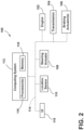
- FIG. 2 a schematic view of one embodiment of a system 100 for generating swath lines for a work vehicle is illustrated in accordance with aspects of the present subject matter.
- the system 100 will be described herein with reference to the work vehicle 10 and the agricultural implement 12 described above with reference to FIG. 1 .
- the disclosed system 100 may generally be used with work vehicles having any other suitable vehicle configuration and/or agricultural implement having any other suitable implement configuration.
- the system 100 includes one or more components of the work vehicle 10.
- the system 100 includes the engine 102 and the transmission 104 of the work vehicle 10.
- the system 100 includes one or more braking actuators 106 of the vehicle 10.
- the braking actuator(s) 106 may reduce the speed at which the vehicle/implement 10/12 moves across the field, such as by converting energy associated with the movement of the vehicle/implement 10/12 into heat.
- the braking actuator(s) 106 may correspond to a suitable hydraulic cylinder(s) configured to push a stationary frictional element(s) (not shown), such as a brake shoe(s) or a brake caliper(s), against a rotating element(s) (not shown), such as a brake drum(s) or a brake disk(s).
- a stationary frictional element(s) such as a brake shoe(s) or a brake caliper(s
- the braking actuator(s) 106 may any other suitable hydraulic, pneumatic, mechanical, and/or electrical component(s) configured to convert the rotation of the rotating element(s) into heat.
- the system 100 may include a steering actuator 108 of the work vehicle 10.
- the steering actuator 108 is configured to adjust the direction of travel 14 of the work vehicle 10.
- the steering actuator 108 may correspond to an electric motor, an electric linear actuator, a hydraulic cylinder, a pneumatic cylinder, or any other suitable actuator coupled to suitable mechanical assembly, such as a rack and pinion or a worm gear assembly.
- the system 100 includes a location sensor 110 may be provided in operative association with the work vehicle 10 and/or the implement 12.
- the location sensor 110 may be configured to determine or otherwise capture data indicative of the current location of the work vehicle 10 and/or the associated implement 12 using a satellite navigation positioning system (e.g., a GPS system, a Galileo positioning system, the Global Navigation satellite system (GLONASS), the BeiDou Satellite Navigation and Positioning system, and/or the like).
- the location data captured by the location sensor 110 may be transmitted to a computing system of the work vehicle 10 and/or the implement 12 (e.g., in the form coordinates) and stored within the computing system's memory for subsequent processing and/or analysis.
- the location data received from the location sensor 110 may be used to geo-locate the vehicle 10 within the field, thereby allowing for recording of the travel path of the vehicle/implement 10/12 across the field.
- the system 100 includes a computing system 112 communicatively coupled to one or more components of the work vehicle 10, the implement 12, and/or the system 100 to allow the operation of such components to be electronically or automatically controlled by the computing system 112.
- the computing system 112 may be communicatively coupled to the location sensor 110 via a communicative link 114.
- the computing system 112 may be configured to receive data (e.g., coordinates) from the location sensor 110 that is indicative of the location of the vehicle/implement 10/12 within the field.
- the computing system 112 may be communicatively coupled to various components of the vehicle 10, such as the engine 102, the transmission 104, the braking actuator(s) 106, and/or the steering actuator 108, via the communicative link 114.
- the computing system 112 may be configured to control the operation of such components 102, 104, 106, 108 to the operation of the vehicle/implement 10/12 (e.g., its direction of travel 14, ground speed, etc.).
- the computing system 112 may be communicatively coupled to any other suitable components of the vehicle 10, the implement 12, and/or the system 100.
- the computing system 112 may comprise one or more processor-based devices, such as a given controller or computing device or any suitable combination of controllers or computing devices.
- the computing system 112 may include one or more processor(s) 116 and associated memory device(s) 118 configured to perform a variety of computer-implemented functions.
- processor refers not only to integrated circuits referred to in the art as being included in a computer, but also refers to a controller, a microcontroller, a microcomputer, a programmable logic circuit (PLC), an application specific integrated circuit, and other programmable circuits.
- the memory device(s) 118 of the computing system 112 may generally comprise memory element(s) including, but not limited to, a computer readable medium (e.g., random access memory RAM)), a computer readable non-volatile medium (e.g., a flash memory), a floppy disk, a compact disk-read only memory (CD-ROM), a magneto-optical disk (MOD), a digital versatile disk (DVD) and/or other suitable memory elements.
- Such memory device(s) 118 may generally be configured to store suitable computer-readable instructions that, when implemented by the processor(s) 116, configure the computing system 112 to perform various computer-implemented functions, such as one or more aspects of the methods and algorithms that will be described herein.
- the computing system 112 may also include various other suitable components, such as a communications circuit or module, one or more input/output channels, a data/control bus and/or the like.
- the various functions of the computing system 112 may be performed by a single processor-based device or may be distributed across any number of processor-based devices, in which instance such devices may be considered to form part of the computing system 112.
- the functions of the computing system 112 may be distributed across multiple application-specific controllers or computing devices, such as a navigation controller, an engine controller, a transmission controller, an implement controller, and/or the like.
- the system 100 may also include a user interface 119.
- the user interface 119 may be configured to provide feedback from the computing system 112 (e.g., feedback associated with generated swath lines) to the operator.
- the user interface 119 may include one or more feedback devices (not shown), such as display screens, speakers, warning lights, and/or the like, which are configured to provide feedback from the computing system 112 to the operator.
- the user interface 119 may, in turn, be communicatively coupled to the computing system 112 via the communicative link 114 to permit the feedback to be transmitted from the computing system 112 to the user interface 119.
- the user interface 119 may include one or more input devices, such as touchscreens, keypads, touchpads, knobs, buttons, sliders, switches, mice, microphones, and/or the like, which are configured to receive inputs from the operator.
- the user interface 119 may be mounted or otherwise positioned within the cab 22 of the work vehicle 10. However, in alternative embodiments, the user interface 119 may mounted at any other suitable location.
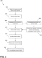
- control logic 200 that may be executed by the computing system 112 (or any other suitable computing system) for generating swath lines for a work vehicle is illustrated in accordance with aspects of the present subject matter.
- the control logic 200 shown in FIG. 3 is representative of steps of one embodiment of an algorithm that can be executed to generate continuous swath lines for a work vehicle that allows the vehicle to make more accurate passes across the field, thereby improving agricultural outcomes and the efficiency of the agricultural operation.
- control logic 200 may be advantageously utilized in association with a system installed on or forming part of a work vehicle to allow for real-time control of generation of continuous swath lines for a work vehicle without requiring substantial computing resources and/or processing time.
- control logic 200 may be used in association with any other suitable system, application, and/or the like for generating swath lines for a work vehicle.
- the control logic 200 includes controlling the operation of a first work vehicle as the first work vehicle makes a first pass across a field.
- the computing system 112 is configured to control the operation of one or more components of the work vehicle 10 and/or the associated implement 12 as the vehicle/implement 10/12 makes a first pass across the field (e.g., to perform an agricultural operation thereon).
- the computing system 112 may transmit control signals to the engine 102, the transmission 104, and/or the braking actuator(s) 106 via the communicative link 114 to control the operation of such components 102, 104, 106 during the first pass.
- the operator may control the direction of travel 14 of the vehicle/implement 10/12.
- the operator may control the operation of the steering actuator 108 via a steering wheel, a joystick, or any other suitable input device.
- the operator generally controls or otherwise dictates the travel path of the vehicle/implement 10/12 during the first pass.
- the control logic 200 includes recording the travel path of the first work vehicle as the vehicle make the first pass across the field based on data captured by a location sensor.
- the computing system 112 may be communicatively coupled to the location sensor 110 via the communicative link 114.
- the computing system 112 may receive data (e.g., coordinates) from the location sensor 110. Such data may, in turn, be indicative of the location of the vehicle/implement 10/12 within the field during the first pass. Based on the received data, the computing system 112 records to the travel path of the vehicle/implement 10/12 during the first pass.
- the control logic 200 includes generating a continuous swath line corresponding to the recorded travel path of the first work vehicle during the first pass.
- the computing system 112 generates a first continuous swath line based on the travel path of the vehicle/implement 10/12 recorded at (206).
- the first continuous swath line provides a continuous (as opposed to discrete) representation of the position or travel path of the vehicle/implement 10/12 during the first pass.
- a continuous swath line provides a more accurate representation of the travel path of the vehicle/implement 10/12 than conventional discrete point-based swath lines.
- the continuous swath line is formed from a plurality of line segments. More specifically, the line segments are joined together end to end to form a continuous line representing the position or travel path of the vehicle/implement 10/12 during the first pass.
- each line segment represents the location of the vehicle/implement 10/12 across a given distance (e.g., ten feet) within the field.
- each line segment may represent the same distance within the field (e.g., each line segment may represent ten feet of a pass).
- the line segments may represent differing distances, such as based on the shape of the line segments.
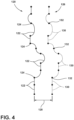
- FIG. 4 illustrates an example first swath line 120 corresponding to a first pass made by the vehicle/implement 10/12.
- the first swath line 120 is formed from a plurality of line segments 122 connected at end points 124.
- swath line 120 provides a continuous indication of the location of the vehicle/implement 10/12 during the first pass.
- the end points 124 are shown in FIG. 4 only to illustrate the line segments 122 forming the swath line 120.
- the swath line 120 is a continuous line.
- any suitable type and/or combination of line segments may be used to form the continuous swath line.
- the line segments may be straight or curved.
- the line segments used to form the continuous swath line may include straight-line segments, circular line segments, and/or clothoid curve line segments.
- the line segments used to form the continuous swath line may include polynomial spline line segments and/or B-spline line segments.
- a continuous swath line improves the operation of the work vehicle 10. More specifically, existing systems generate swath lines formed from a plurality of discrete location points within the field. Such point-based swath lines provide no indication of how a work vehicle is to travel between the location points. As such, existing systems must guess how the work vehicle is to move from one point to the next. Thus, a work vehicle relying on point-based swath lines generally makes less accurate passes across the field, which may result in reduced crop yield or inefficient performance of the agricultural operation (e.g., the need to make unnecessary passes across the field, which wastes fuel and time).
- continuous swath lines provide constant guidance as where the vehicle 10 is to be located during a pass across field (as opposed to at guidance only at a series of spaced apart locations).
- a vehicle relying on a continuous swath line for guidance knows where to be within the field at all times. Accordingly, a work vehicle relying continuous swath lines makes more accurate passes across the field, which improves crop yield and/or agricultural operation efficiency.
- the control logic 200 includes propagating the first swath line across the field.
- the computing system 112 may propagate the first swath line generated at (206) across the field as one or more additional swath lines.
- the computing system 112 may generate a second continuous swath line across the field corresponding to a second pass (which has not yet been made) based on the first continuous swath line generated at (206).
- the second continuous swath line may have the same or a substantially similar shape to the first swath line.
- the second swath line is spaced apart from the first swath line in the lateral direction by the swath width of the vehicle/implement 10/12.
- the computing system 112 may generate a third swath line spaced apart from the second swath line by the swath width of the vehicle/implement 10/12 and so on.
- the computing system 112 may generate any suitable number of swath lines based on the first swath line.
- the vehicle/implement 10/12 may be automatically guided along the propagated swath line(s).
- FIG. 4 further illustrates an example second swath line 126 generated based on the first swath line 120.
- the second swath line 126 corresponds to a second pass to be made by the vehicle/implement 10/12.
- the second swath line 126 is substantially the same as the first swath line 120 but spaced apart from the first swath line 120 by a swath width of the vehicle/implement 10/12 (e.g., as indicated by arrow 128).
- the second swath line 126 is formed from a plurality of line segments 130 connected at end points 132. The end points 132 are shown in FIG. 4 only to illustrate the line segments 130 forming the swath line 126.
- the swath line 126 is a continuous line.
- the control logic 200 includes controlling the operation of the first work vehicle such that the vehicle automatically travels along the propagated swath line(s).
- the computing system 112 is configured to control the operation of the vehicle/implement 10/12 such that the vehicle/implement 10/12 automatically travels along the propagated swath line(s) generated at (208).
- the computing system 112 may transmit control signals to the steering actuator 108 via the communicative link 114.
- the control signals instruct the steering actuator 108 to automatically adjust the direction of travel 14 of the vehicle/implement 10/12 such that the vehicle/implement 10/12 travels along the second swath line, the third swath line, and so on.
- the propagated swath line(s) allow the vehicle/implement 10/12 to automatically travel back and forth across the field after the operator has made a first pass (e.g., along a boundary).
- the control logic 200 proceeds to (212).
- the first swath line is not propagated across the field. Instead, the operator may manually control the travel path of the vehicle/implement 10/12 along each successive pass across the field. In such instances, (202) - (206) may be repeated for each successive pass made across the field such continuous swath lines for each pass are generated based on the recorded position of the vehicle/implement 10/12 during each pass. Thereafter, the control logic 200 may skip (208) and (210) and proceed to (212).
- the control logic 200 includes storing the generated continuous swath line(s) within one or more memory devices.
- the computing system 112 may be configured to store the generated swath lines (e.g., the swath line(s) generated at (206) and/or propagated at (208)) within its memory device(s) 118 (or any other suitable memory device(s)) for subsequent use.
- the control logic 200 includes accessing the stored continuous swath line(s) from the one or more memory devices.
- the computing system 112 may be configured to access the stored continuous swath line(s) from its memory device(s) 118 (or any other suitable memory device(s)).
- the accessed continuous swath line(s) may be used to guide a second work vehicle across the field, such as during a subsequent agricultural operation.
- the control logic 200 includes manipulating the accessed continuous swath line.
- the computing system 112 may manipulate or otherwise adjust the accessed continuous swath line(s) based on a parameter(s) of the second work vehicle.
- the computing system 112 may adjust the curvature of curved portions of the accessed continuous swath line(s) to accommodate differences in the maximum steering angles of the vehicle/implement 10/12 and a second work vehicle.
- the accessed continuous swath line(s) are not manipulated, such as when the accessed continuous swath line(s) are being used to control the vehicle/implement 10/12 or another similar vehicle.
- the control logic 200 includes controlling the operation of a second work vehicle such that the second vehicle automatically travels along the manipulated swath line(s).
- the computing system 112 is configured to control the operation of a second work vehicle such that the second vehicle automatically travels along the swath line(s) manipulated at (216).
- the computing system 112 may transmit control signals to the steering actuator of the second vehicle via the communicative link 114.
- the control signals instruct the steering actuator to automatically adjust the direction of travel of the second vehicle such that the second vehicle travels along the manipulated swath line(s).
- the computing system 112 may be configured to display any of the generated, propagated, stored, accessed, and/or manipulated swath lines to the operator of the vehicle/implement 10/12 and or the second vehicle. For example, the computing system 112 may initiate display of any such swath lines on the user interface 119.
- FIG. 5 a flow diagram of one embodiment of a method 300 for generating swath lines for a work vehicle is illustrated in accordance with aspects of the present subject matter.
- the method 300 will be described herein with reference to the work vehicle 10, the agricultural implement 12, and the system 100 described above with reference to FIGS. 1-4 .
- the disclosed method 300 may generally be implemented with any work vehicle having any suitable vehicle configuration, with any agricultural implement having any suitable implement configuration, and/or any within system having any suitable system configuration.
- FIG. 5 depicts steps performed in a particular order for purposes of illustration and discussion, the methods discussed herein are not limited to any particular order or arrangement. The various steps of the methods disclosed herein can be omitted, rearranged, combined, and/or adapted in various ways without deviating from the scope of the present disclosure.
- the method 300 includes controlling, with a computing system, the operation of a work vehicle as the work vehicle makes a first pass across the field.
- the computing system 112 may control operation of one or more components of the work vehicle 10, such as the engine 102, the transmission 104, and/or the braking actuator(s) 106, as the work vehicle 10 makes a first pass across a field (e.g., to perform an agricultural operation thereon).
- the method 300 includes recording, with the computing system, a travel path of the work vehicle across the field based on data captured by a location sensor.
- the computing system 112 may record the travel path of the work vehicle 10 across the field based on data (e.g., coordinates) captured by and received from the location sensor 110.
- the method 300 includes generating, with the computing system, a continuous swath line formed from a plurality of line segments such that the continuous swath line corresponds to the recorded travel path of the work vehicle.
- the computing system 112 may generate a continuous swath line formed from a plurality of line segments such that the continuous swath line corresponds to the recorded travel path of the work vehicle 10.
- the steps of the control logic 200 and the method 300 are performed by the computing system 112 upon loading and executing software code or instructions which are tangibly stored on a tangible computer readable medium, such as on a magnetic medium, e.g., a computer hard drive, an optical medium, e.g., an optical disc, solid-state memory, e.g., flash memory, or other storage media known in the art.
- a tangible computer readable medium such as on a magnetic medium, e.g., a computer hard drive, an optical medium, e.g., an optical disc, solid-state memory, e.g., flash memory, or other storage media known in the art.
- any of the functionality performed by the computing system 112 described herein, such as the control logic 200 and the method 300 is implemented in software code or instructions which are tangibly stored on a tangible computer readable medium.
- the computing system 112 loads the software code or instructions via a direct interface with the computer readable medium or via a wired and/or wireless network. Upon loading
Landscapes
- Engineering & Computer Science (AREA)
- Life Sciences & Earth Sciences (AREA)
- Remote Sensing (AREA)
- Radar, Positioning & Navigation (AREA)
- Physics & Mathematics (AREA)
- Environmental Sciences (AREA)
- Mechanical Engineering (AREA)
- General Physics & Mathematics (AREA)
- Soil Sciences (AREA)
- Aviation & Aerospace Engineering (AREA)
- Automation & Control Theory (AREA)
- Transportation (AREA)
- Combustion & Propulsion (AREA)
- Chemical & Material Sciences (AREA)
- Computer Networks & Wireless Communication (AREA)
- Guiding Agricultural Machines (AREA)
- Control Of Position, Course, Altitude, Or Attitude Of Moving Bodies (AREA)
Abstract
Description
- The present disclosure generally relates to work vehicles and, more particularly, to systems and methods for generating swath lines for a work vehicle, such as an agricultural or construction vehicle.
- Modern farming practices strive to increase yields of agricultural fields. As such, agricultural work vehicles, such as tractors, sprayers, harvesters, and/or the like, are used to perform agricultural operations on a field. In general, when performing an agricultural operation, it is necessary for the work vehicle to make a series of passes across the field. However, it is difficult for an operator to control the work vehicle such that passes are consistent and uniformly spaced apart. Inconsistent or non-uniformly spaced passes may result in lower crop yields and/or inefficient performance of the agricultural operation. In this respect, systems have been developed for generating swath lines or guidance lines for guiding a work vehicle along each pass across the field. While such systems work well, further improvements are needed.
- Accordingly, an improved system and method for generating swath lines for a work vehicle would be welcomed in the technology.
- Aspects and advantages of the technology will be set forth in part in the following description, or may be obvious from the description, or may be learned through practice of the technology.
- In one aspect, the present subject matter is directed to a work vehicle. The work vehicle includes a frame configured to support a plurality of components of the work vehicle. Furthermore, the work vehicle includes a location sensor configured to capture data indicative of a location of the work vehicle within a field. Additionally, the work vehicle includes a computing system communicatively coupled to the location sensor. The computing system is configured to control an operation of the plurality of components as the work vehicle makes a first pass across the field. Moreover, the computing system is configured to record a travel path of the work vehicle as the work vehicle make the first pass across the field based on data captured by the location sensor. In addition, the computing system is configured to generate a continuous swath line formed from a plurality of line segments such that the continuous swath line corresponds to the recorded travel path of the work vehicle.
- In another aspect, the present subject matter is directed to a system for generating swath lines for a work vehicle. The system includes a location sensor configured to capture data indicative of a location of the work vehicle within a field. Furthermore, the system includes a computing system communicatively coupled to the location sensor. The computing system is configured to control an operation of the work vehicle as the work vehicle makes a first pass across the field. Additionally, the computing system is configured to record a travel path of the work vehicle as the work vehicle make the first pass across the field based on data captured by the location sensor. Moreover, the computing system is configured to generate a continuous swath line formed from a plurality of line segments such that the continuous swath line corresponds to the recorded travel path of the work vehicle.
- In a further aspect, the present subject matter is directed to a method for generating swath lines for a work vehicle. The work vehicle, in turn, includes a location sensor configured to capture data indicative of a location of the work vehicle within a field. The method includes controlling, with a computing system, an operation of the work vehicle as the work vehicle makes a first pass across the field. In addition, the method includes recording, with the computing system, a travel path of the work vehicle across the field based on data captured by the location sensor. Furthermore, the method includes generating, with the computing system, a continuous swath line formed from a plurality of line segments such that the continuous swath line corresponds to the recorded travel path of the work vehicle.
- These and other features, aspects and advantages of the present technology will become better understood with reference to the following description and appended claims. The accompanying drawings, which are incorporated in and constitute a part of this specification, illustrate embodiments of the technology and, together with the description, serve to explain the principles of the technology.
- A full and enabling disclosure of the present technology, including the best mode thereof, directed to one of ordinary skill in the art, is set forth in the specification, which makes reference to the appended figures, in which:
-
FIG. 1 illustrates a perspective view of one embodiment of a work vehicle and an associated agricultural implement in accordance with aspects of the present subject matter; -
FIG. 2 illustrates a schematic view of one embodiment of a system for generating swath lines for a work vehicle in accordance with aspects of the present subject matter; -
FIG. 3 illustrates a flow diagram providing one embodiment of control logic for generating swath lines for a work vehicle in accordance with aspects of the present subject matter; -
FIG. 4 illustrates a diagrammatic view of example first and second swath lines in accordance with aspects of the present subject matter; and -
FIG. 5 illustrates a flow diagram of one embodiment of a method for generating swath lines for a work vehicle in accordance with aspects of the present subject matter. - Repeat use of reference characters in the present specification and drawings is intended to represent the same or analogous features or elements of the present technology.
- Reference now will be made in detail to embodiments of the invention, one or more examples of which are illustrated in the drawings. Each example is provided by way of explanation of the invention, not limitation of the invention. In fact, it will be apparent to those skilled in the art that various modifications and variations can be made in the present invention. For instance, features illustrated or described as part of one embodiment can be used with another embodiment to yield a still further embodiment. Thus, it is intended that the present invention covers such modifications and variations as come within the scope of the appended claims and their equivalents.
- In general, the present subject matter is directed to a system and a method for generating swath lines for a work vehicle. Specifically, in several embodiments, a computing system of the disclosed system is configured to control the operation of the work vehicle as the vehicle makes a first pass across the field. In some embodiments, an operator may control the direction of travel of the work vehicle during the first pass. As the work vehicle makes the first pass, the computing system records the travel path of the vehicle based on data (e.g., coordinates) captured by a location sensor. Thereafter, the computing system generates a continuous swath line formed from a plurality of line segments such that the continuous swath line corresponds to the recorded travel path of the work vehicle. For example, in one embodiment. the line segments may include straight line segments, circular line segments, and/or clothoid curve line segments. In another embodiment, the line segments may include polynomial spline line segments and/or B-spline line segments.
- The generation of a continuous swath line improves the operation of the work vehicle. More specifically, existing systems generate swath lines formed from a plurality of discrete location points within the field. Such point-based swath lines provide no indication of how a work vehicle is to travel between the location points. As such, existing systems must guess how the work vehicle is to move from one point to the next. Thus, a work vehicle relying on point-based swath lines generally makes less accurate passes across the field, which may result in reduced crop yield or inefficient performance of the agricultural operation (e.g., the need to make unnecessary passes across the field, which wastes fuel and time). However, as described above, the disclosed system and method generates continuous swath lines, with each continuous swath line being formed of a plurality of line segments. In this respect, such continuous swath lines provide constant guidance as where the vehicle is to be located during a pass across field (as opposed to at guidance only at a series of spaced locations). Accordingly, a work vehicle relying on continuous swath lines makes more accurate passes across the field, which improves crop yield and/or agricultural operation efficiency.
- Referring now to the drawings,
FIG. 1 illustrates a perspective view of awork vehicle 10 towing an associatedagricultural implement 12 across a field in a direction of travel (indicated by arrow 14). In the illustrated embodiment, thework vehicle 10 is configured as an agricultural vehicle (e.g., an agricultural tractor) and theagricultural implement 12 is configured as a tillage implement (e.g., a disk ripper). However, in alternative embodiments, thework vehicle 10 may correspond to any other suitable type of agricultural vehicle (e.g., an agricultural harvester, a self-propelled sprayer, etc.) or construction vehicle (e.g., dozer, loader, grader, etc.) and the agricultural implement 12 may correspond to any other suitable type of agricultural implement (e.g., a seed-planting implement, a towable sprayer, etc.). Additionally, in some embodiments, thevehicle 10 may not be configured to tow an implement. - As shown in
FIG. 1 , thevehicle 10 includes a pair offront track assemblies 16, a pair ofrear track assemblies 18, and a frame orchassis 20 coupled to and supported by thetrack assemblies cab 22 may be supported by a portion of thechassis 20 and may house various input devices for permitting an operator to control the operation of one or more components of thevehicle 10 and/or one or more components of the implement 12. Furthermore, thevehicle 10 may include anengine 102 and atransmission 104 mounted on thechassis 20. Thetransmission 104 may be operably coupled to theengine 102 and may provide variably adjusted gear ratios for transferring engine power to thetrack assemblies - Additionally, as shown in
FIG. 1 , the implement 12 includes aframe 24. More specifically, theframe 24 generally includes a plurality ofstructural frame members 26, such as beams, bars, and/or the like, which are configured to support or couple to a plurality of components. For example, as will be described below, theframe 24 may be configured to support one or more ground-engaging tools configured to perform an agricultural operation on a field as the implement 12 travels across the field. Furthermore, ahitch assembly 28 may be connected to theframe 24 and configured to couple the implement 12 to thevehicle 10. - In several embodiments, the
frame 24 may support one or more gangs or sets ofdisk blades 30. Eachdisk blade 30 may, in turn, be configured to penetrate into or otherwise engage the soil as the implement 12 is pulled through the field. In this regard, the various gangs ofdisk blades 30 may be oriented at an angle relative to the direction oftravel 14 to promote more effective tilling of the soil. In the embodiment shown inFIG. 1 , the implement 12 includes four gangs ofdisk blades 30 supported on theframe 24 adjacent to its forward end. However, in alternative embodiments, the implement 12 may include any other suitable number of gangs. Furthermore, in one embodiment, the gangs ofdisk blades 30 may be mounted to theframe 24 at any other suitable location, such as adjacent to its aft end. - Moreover, in several embodiments, the implement
frame 24 may be configured to support other ground-engaging tools. For instance, in the illustrated embodiment, theframe 24 is configured to support a plurality ofshanks 32. As shown, theshanks 32 are spaced apart from each other on theframe 24 in a lateral direction of the implement 12. The lateral direction, in turn, extends perpendicular to the direction oftravel 14. As such, theshanks 32 are configured to rip or otherwise till the soil as the implement 12 is towed across the field. Furthermore, in the illustrated embodiment, theframe 24 is also configured to support a plurality of levelingblades 34 and a plurality of rolling (or crumbler)basket assemblies 36 positioned aft of theshanks 32. In such an embodiment, theleveling blades 34 may be spaced apart from each other in the lateral direction. However, in other embodiments, any other suitable ground-engaging tools may be coupled to and supported by the implementframe 24. - The configuration of the
work vehicle 10 and the associated agricultural implement 12 described above and shown inFIG. 1 is provided only to place the present subject matter in an exemplary field of use. Thus, the present subject matter may be readily adaptable to any manner of work vehicle and/or implement configuration. - Referring now to
FIG. 2 , a schematic view of one embodiment of asystem 100 for generating swath lines for a work vehicle is illustrated in accordance with aspects of the present subject matter. In general, thesystem 100 will be described herein with reference to thework vehicle 10 and the agricultural implement 12 described above with reference toFIG. 1 . However, the disclosedsystem 100 may generally be used with work vehicles having any other suitable vehicle configuration and/or agricultural implement having any other suitable implement configuration. - As shown in
FIG. 2 , thesystem 100 includes one or more components of thework vehicle 10. For example, in the illustrated embodiment, thesystem 100 includes theengine 102 and thetransmission 104 of thework vehicle 10. Additionally, in the illustrated embodiment, thesystem 100 includes one ormore braking actuators 106 of thevehicle 10. In general, when activated, the braking actuator(s) 106 may reduce the speed at which the vehicle/implement 10/12 moves across the field, such as by converting energy associated with the movement of the vehicle/implement 10/12 into heat. For example, in one embodiment, the braking actuator(s) 106 may correspond to a suitable hydraulic cylinder(s) configured to push a stationary frictional element(s) (not shown), such as a brake shoe(s) or a brake caliper(s), against a rotating element(s) (not shown), such as a brake drum(s) or a brake disk(s). However, in alternative embodiments, the braking actuator(s) 106 may any other suitable hydraulic, pneumatic, mechanical, and/or electrical component(s) configured to convert the rotation of the rotating element(s) into heat. - Furthermore, in several embodiments, the
system 100 may include asteering actuator 108 of thework vehicle 10. In general, thesteering actuator 108 is configured to adjust the direction oftravel 14 of thework vehicle 10. For example, thesteering actuator 108 may correspond to an electric motor, an electric linear actuator, a hydraulic cylinder, a pneumatic cylinder, or any other suitable actuator coupled to suitable mechanical assembly, such as a rack and pinion or a worm gear assembly. - Moreover, the
system 100 includes alocation sensor 110 may be provided in operative association with thework vehicle 10 and/or the implement 12. In general, thelocation sensor 110 may be configured to determine or otherwise capture data indicative of the current location of thework vehicle 10 and/or the associated implement 12 using a satellite navigation positioning system (e.g., a GPS system, a Galileo positioning system, the Global Navigation satellite system (GLONASS), the BeiDou Satellite Navigation and Positioning system, and/or the like). In such an embodiment, the location data captured by thelocation sensor 110 may be transmitted to a computing system of thework vehicle 10 and/or the implement 12 (e.g., in the form coordinates) and stored within the computing system's memory for subsequent processing and/or analysis. Thus, the location data received from thelocation sensor 110 may be used to geo-locate thevehicle 10 within the field, thereby allowing for recording of the travel path of the vehicle/implement 10/12 across the field. - In addition, the
system 100 includes acomputing system 112 communicatively coupled to one or more components of thework vehicle 10, the implement 12, and/or thesystem 100 to allow the operation of such components to be electronically or automatically controlled by thecomputing system 112. For instance, thecomputing system 112 may be communicatively coupled to thelocation sensor 110 via acommunicative link 114. As such, thecomputing system 112 may be configured to receive data (e.g., coordinates) from thelocation sensor 110 that is indicative of the location of the vehicle/implement 10/12 within the field. Furthermore, thecomputing system 112 may be communicatively coupled to various components of thevehicle 10, such as theengine 102, thetransmission 104, the braking actuator(s) 106, and/or thesteering actuator 108, via thecommunicative link 114. In this respect, thecomputing system 112 may be configured to control the operation ofsuch components travel 14, ground speed, etc.). In addition, thecomputing system 112 may be communicatively coupled to any other suitable components of thevehicle 10, the implement 12, and/or thesystem 100. - In general, the
computing system 112 may comprise one or more processor-based devices, such as a given controller or computing device or any suitable combination of controllers or computing devices. Thus, in several embodiments, thecomputing system 112 may include one or more processor(s) 116 and associated memory device(s) 118 configured to perform a variety of computer-implemented functions. As used herein, the term "processor" refers not only to integrated circuits referred to in the art as being included in a computer, but also refers to a controller, a microcontroller, a microcomputer, a programmable logic circuit (PLC), an application specific integrated circuit, and other programmable circuits. Additionally, the memory device(s) 118 of thecomputing system 112 may generally comprise memory element(s) including, but not limited to, a computer readable medium (e.g., random access memory RAM)), a computer readable non-volatile medium (e.g., a flash memory), a floppy disk, a compact disk-read only memory (CD-ROM), a magneto-optical disk (MOD), a digital versatile disk (DVD) and/or other suitable memory elements. Such memory device(s) 118 may generally be configured to store suitable computer-readable instructions that, when implemented by the processor(s) 116, configure thecomputing system 112 to perform various computer-implemented functions, such as one or more aspects of the methods and algorithms that will be described herein. In addition, thecomputing system 112 may also include various other suitable components, such as a communications circuit or module, one or more input/output channels, a data/control bus and/or the like. - The various functions of the
computing system 112 may be performed by a single processor-based device or may be distributed across any number of processor-based devices, in which instance such devices may be considered to form part of thecomputing system 112. For instance, the functions of thecomputing system 112 may be distributed across multiple application-specific controllers or computing devices, such as a navigation controller, an engine controller, a transmission controller, an implement controller, and/or the like. - In addition, the
system 100 may also include auser interface 119. More specifically, theuser interface 119 may be configured to provide feedback from the computing system 112 (e.g., feedback associated with generated swath lines) to the operator. As such, theuser interface 119 may include one or more feedback devices (not shown), such as display screens, speakers, warning lights, and/or the like, which are configured to provide feedback from thecomputing system 112 to the operator. As such, theuser interface 119 may, in turn, be communicatively coupled to thecomputing system 112 via thecommunicative link 114 to permit the feedback to be transmitted from thecomputing system 112 to theuser interface 119. Furthermore, some embodiments of theuser interface 119 may include one or more input devices, such as touchscreens, keypads, touchpads, knobs, buttons, sliders, switches, mice, microphones, and/or the like, which are configured to receive inputs from the operator. In one embodiment, theuser interface 119 may be mounted or otherwise positioned within thecab 22 of thework vehicle 10. However, in alternative embodiments, theuser interface 119 may mounted at any other suitable location. - Referring now to
FIG. 3 , a flow diagram of one embodiment ofcontrol logic 200 that may be executed by the computing system 112 (or any other suitable computing system) for generating swath lines for a work vehicle is illustrated in accordance with aspects of the present subject matter. Specifically, thecontrol logic 200 shown inFIG. 3 is representative of steps of one embodiment of an algorithm that can be executed to generate continuous swath lines for a work vehicle that allows the vehicle to make more accurate passes across the field, thereby improving agricultural outcomes and the efficiency of the agricultural operation. Thus, in several embodiments, thecontrol logic 200 may be advantageously utilized in association with a system installed on or forming part of a work vehicle to allow for real-time control of generation of continuous swath lines for a work vehicle without requiring substantial computing resources and/or processing time. However, in other embodiments, thecontrol logic 200 may be used in association with any other suitable system, application, and/or the like for generating swath lines for a work vehicle. - As shown, at (202), the
control logic 200 includes controlling the operation of a first work vehicle as the first work vehicle makes a first pass across a field. Specifically, in several embodiments, thecomputing system 112 is configured to control the operation of one or more components of thework vehicle 10 and/or the associated implement 12 as the vehicle/implement 10/12 makes a first pass across the field (e.g., to perform an agricultural operation thereon). For example, thecomputing system 112 may transmit control signals to theengine 102, thetransmission 104, and/or the braking actuator(s) 106 via thecommunicative link 114 to control the operation ofsuch components - As the vehicle/implement 10/12 makes the first pass across the field, the operator may control the direction of
travel 14 of the vehicle/implement 10/12. For example, during the first pass, the operator may control the operation of thesteering actuator 108 via a steering wheel, a joystick, or any other suitable input device. Thus, the operator generally controls or otherwise dictates the travel path of the vehicle/implement 10/12 during the first pass. - Furthermore, at (204), the
control logic 200 includes recording the travel path of the first work vehicle as the vehicle make the first pass across the field based on data captured by a location sensor. Specifically, as mentioned above, in several embodiments, thecomputing system 112 may be communicatively coupled to thelocation sensor 110 via thecommunicative link 114. In this respect, as the vehicle/implement 10/12 makes the first pass across the field, thecomputing system 112 may receive data (e.g., coordinates) from thelocation sensor 110. Such data may, in turn, be indicative of the location of the vehicle/implement 10/12 within the field during the first pass. Based on the received data, thecomputing system 112 records to the travel path of the vehicle/implement 10/12 during the first pass. - Additionally, at (206), the
control logic 200 includes generating a continuous swath line corresponding to the recorded travel path of the first work vehicle during the first pass. Specifically, in several embodiments, thecomputing system 112 generates a first continuous swath line based on the travel path of the vehicle/implement 10/12 recorded at (206). As such, the first continuous swath line provides a continuous (as opposed to discrete) representation of the position or travel path of the vehicle/implement 10/12 during the first pass. As will be described below, such a continuous swath line provides a more accurate representation of the travel path of the vehicle/implement 10/12 than conventional discrete point-based swath lines. - At (206), the continuous swath line is formed from a plurality of line segments. More specifically, the line segments are joined together end to end to form a continuous line representing the position or travel path of the vehicle/implement 10/12 during the first pass. Thus, each line segment represents the location of the vehicle/implement 10/12 across a given distance (e.g., ten feet) within the field. In some embodiments, each line segment may represent the same distance within the field (e.g., each line segment may represent ten feet of a pass). Alternatively, the line segments may represent differing distances, such as based on the shape of the line segments.
- For example,
FIG. 4 illustrates an examplefirst swath line 120 corresponding to a first pass made by the vehicle/implement 10/12. As shown, thefirst swath line 120 is formed from a plurality ofline segments 122 connected at end points 124. Thus,swath line 120 provides a continuous indication of the location of the vehicle/implement 10/12 during the first pass. The end points 124 are shown inFIG. 4 only to illustrate theline segments 122 forming theswath line 120. In practice, theswath line 120 is a continuous line. - Any suitable type and/or combination of line segments may be used to form the continuous swath line. The line segments may be straight or curved. For example, in one embodiment, the line segments used to form the continuous swath line may include straight-line segments, circular line segments, and/or clothoid curve line segments. In another embodiment, the line segments used to form the continuous swath line may include polynomial spline line segments and/or B-spline line segments.
- The generation of a continuous swath line improves the operation of the
work vehicle 10. More specifically, existing systems generate swath lines formed from a plurality of discrete location points within the field. Such point-based swath lines provide no indication of how a work vehicle is to travel between the location points. As such, existing systems must guess how the work vehicle is to move from one point to the next. Thus, a work vehicle relying on point-based swath lines generally makes less accurate passes across the field, which may result in reduced crop yield or inefficient performance of the agricultural operation (e.g., the need to make unnecessary passes across the field, which wastes fuel and time). However, continuous swath lines provide constant guidance as where thevehicle 10 is to be located during a pass across field (as opposed to at guidance only at a series of spaced apart locations). A vehicle relying on a continuous swath line for guidance knows where to be within the field at all times. Accordingly, a work vehicle relying continuous swath lines makes more accurate passes across the field, which improves crop yield and/or agricultural operation efficiency. - Referring again to
FIG. 3 , at (208), thecontrol logic 200 includes propagating the first swath line across the field. Specifically, in several embodiments, thecomputing system 112 may propagate the first swath line generated at (206) across the field as one or more additional swath lines. For example, in such embodiments, thecomputing system 112 may generate a second continuous swath line across the field corresponding to a second pass (which has not yet been made) based on the first continuous swath line generated at (206). In general, the second continuous swath line may have the same or a substantially similar shape to the first swath line. However, the second swath line is spaced apart from the first swath line in the lateral direction by the swath width of the vehicle/implement 10/12. Thereafter, thecomputing system 112 may generate a third swath line spaced apart from the second swath line by the swath width of the vehicle/implement 10/12 and so on. At (208), thecomputing system 112 may generate any suitable number of swath lines based on the first swath line. As will be described below, in some embodiments, the vehicle/implement 10/12 may be automatically guided along the propagated swath line(s). - For example,
FIG. 4 further illustrates an examplesecond swath line 126 generated based on thefirst swath line 120. In general, thesecond swath line 126 corresponds to a second pass to be made by the vehicle/implement 10/12. As shown, thesecond swath line 126 is substantially the same as thefirst swath line 120 but spaced apart from thefirst swath line 120 by a swath width of the vehicle/implement 10/12 (e.g., as indicated by arrow 128). Additionally, like thefirst swath line 120, thesecond swath line 126 is formed from a plurality ofline segments 130 connected at end points 132. The end points 132 are shown inFIG. 4 only to illustrate theline segments 130 forming theswath line 126. In practice, theswath line 126 is a continuous line. - Referring again to
FIG. 3 , at (210), thecontrol logic 200 includes controlling the operation of the first work vehicle such that the vehicle automatically travels along the propagated swath line(s). Specifically, in several embodiments, thecomputing system 112 is configured to control the operation of the vehicle/implement 10/12 such that the vehicle/implement 10/12 automatically travels along the propagated swath line(s) generated at (208). For example, thecomputing system 112 may transmit control signals to thesteering actuator 108 via thecommunicative link 114. The control signals, in turn, instruct thesteering actuator 108 to automatically adjust the direction oftravel 14 of the vehicle/implement 10/12 such that the vehicle/implement 10/12 travels along the second swath line, the third swath line, and so on. Thus, the propagated swath line(s) allow the vehicle/implement 10/12 to automatically travel back and forth across the field after the operator has made a first pass (e.g., along a boundary). As will be described below, after completion of (210), thecontrol logic 200 proceeds to (212). - In alternative embodiments, the first swath line is not propagated across the field. Instead, the operator may manually control the travel path of the vehicle/implement 10/12 along each successive pass across the field. In such instances, (202) - (206) may be repeated for each successive pass made across the field such continuous swath lines for each pass are generated based on the recorded position of the vehicle/implement 10/12 during each pass. Thereafter, the
control logic 200 may skip (208) and (210) and proceed to (212). - At (212), the
control logic 200 includes storing the generated continuous swath line(s) within one or more memory devices. Specifically, in several embodiments, thecomputing system 112 may be configured to store the generated swath lines (e.g., the swath line(s) generated at (206) and/or propagated at (208)) within its memory device(s) 118 (or any other suitable memory device(s)) for subsequent use. - Furthermore, at (214), the
control logic 200 includes accessing the stored continuous swath line(s) from the one or more memory devices. Specifically, in several embodiments, thecomputing system 112 may be configured to access the stored continuous swath line(s) from its memory device(s) 118 (or any other suitable memory device(s)). For example, the accessed continuous swath line(s) may be used to guide a second work vehicle across the field, such as during a subsequent agricultural operation. - Additionally, at (216), the
control logic 200 includes manipulating the accessed continuous swath line. Specifically, in several embodiments, when the accessed continuous swath line(s) are being used to guide a second work vehicle, thecomputing system 112 may manipulate or otherwise adjust the accessed continuous swath line(s) based on a parameter(s) of the second work vehicle. For example, thecomputing system 112 may adjust the curvature of curved portions of the accessed continuous swath line(s) to accommodate differences in the maximum steering angles of the vehicle/implement 10/12 and a second work vehicle. Alternatively, in some embodiments, the accessed continuous swath line(s) are not manipulated, such as when the accessed continuous swath line(s) are being used to control the vehicle/implement 10/12 or another similar vehicle. - Moreover, at (218), the
control logic 200 includes controlling the operation of a second work vehicle such that the second vehicle automatically travels along the manipulated swath line(s). Specifically, in several embodiments, thecomputing system 112 is configured to control the operation of a second work vehicle such that the second vehicle automatically travels along the swath line(s) manipulated at (216). For example, thecomputing system 112 may transmit control signals to the steering actuator of the second vehicle via thecommunicative link 114. The control signals, in turn, instruct the steering actuator to automatically adjust the direction of travel of the second vehicle such that the second vehicle travels along the manipulated swath line(s). - In addition, the
computing system 112 may be configured to display any of the generated, propagated, stored, accessed, and/or manipulated swath lines to the operator of the vehicle/implement 10/12 and or the second vehicle. For example, thecomputing system 112 may initiate display of any such swath lines on theuser interface 119. - Referring now to
FIG. 5 , a flow diagram of one embodiment of amethod 300 for generating swath lines for a work vehicle is illustrated in accordance with aspects of the present subject matter. In general, themethod 300 will be described herein with reference to thework vehicle 10, the agricultural implement 12, and thesystem 100 described above with reference toFIGS. 1-4 . However, the disclosedmethod 300 may generally be implemented with any work vehicle having any suitable vehicle configuration, with any agricultural implement having any suitable implement configuration, and/or any within system having any suitable system configuration. In addition, althoughFIG. 5 depicts steps performed in a particular order for purposes of illustration and discussion, the methods discussed herein are not limited to any particular order or arrangement. The various steps of the methods disclosed herein can be omitted, rearranged, combined, and/or adapted in various ways without deviating from the scope of the present disclosure. - As shown in
FIG. 5 , at (302), themethod 300 includes controlling, with a computing system, the operation of a work vehicle as the work vehicle makes a first pass across the field. For instance, as described above, thecomputing system 112 may control operation of one or more components of thework vehicle 10, such as theengine 102, thetransmission 104, and/or the braking actuator(s) 106, as thework vehicle 10 makes a first pass across a field (e.g., to perform an agricultural operation thereon). - Additionally, at (304), the
method 300 includes recording, with the computing system, a travel path of the work vehicle across the field based on data captured by a location sensor. For instance, as described above, thecomputing system 112 may record the travel path of thework vehicle 10 across the field based on data (e.g., coordinates) captured by and received from thelocation sensor 110. - Moreover, as shown in
FIG. 5 , at (306), themethod 300 includes generating, with the computing system, a continuous swath line formed from a plurality of line segments such that the continuous swath line corresponds to the recorded travel path of the work vehicle. For instance, as described above, thecomputing system 112 may generate a continuous swath line formed from a plurality of line segments such that the continuous swath line corresponds to the recorded travel path of thework vehicle 10. - It is to be understood that the steps of the
control logic 200 and themethod 300 are performed by thecomputing system 112 upon loading and executing software code or instructions which are tangibly stored on a tangible computer readable medium, such as on a magnetic medium, e.g., a computer hard drive, an optical medium, e.g., an optical disc, solid-state memory, e.g., flash memory, or other storage media known in the art. Thus, any of the functionality performed by thecomputing system 112 described herein, such as thecontrol logic 200 and themethod 300, is implemented in software code or instructions which are tangibly stored on a tangible computer readable medium. Thecomputing system 112 loads the software code or instructions via a direct interface with the computer readable medium or via a wired and/or wireless network. Upon loading and executing such software code or instructions by thecomputing system 112, thecomputing system 112 may perform any of the functionality of thecomputing system 112 described herein, including any steps of thecontrol logic 200 and themethod 300 described herein.
Claims (15)
- A system (100) for generating swath lines for a work vehicle (10), the system (100) comprising a location sensor (110) configured to capture data indicative of a location of the work vehicle (10) within a field and a computing system (112) communicatively coupled to the location sensor (110), the computing system (112) configured to control an operation of the work vehicle (10) as the work vehicle (10) makes a first pass across the field and record a travel path of the work vehicle (10) as the work vehicle (10) makes the first pass across the field based on data captured by the location sensor (110), the system characterized by the computing system being further configured to:
generate a continuous swath line formed from a plurality of line segments such that the continuous swath line corresponds to the recorded travel path of the work vehicle (10). - The system (100) as in claim 1, wherein the plurality of line segments comprises at least one of a straight-line segment, a circular line segment, or a clothoid curve line segment.
- The system (100) as in any preceding claim, wherein the plurality of line segments comprises at least one of a polynomial spline line segment or a B-spline line segment.
- The system (100) as in any preceding claim, wherein the continuous swath line corresponds to a first continuous swath line, the computing system (112) further configured to:generate a second continuous swath line across the field corresponding to a second pass based on the first continuous swath line, the second continuous swath line being spaced apart from the first swath line by a swath width of the work vehicle (10); andcontrol the operation of the work vehicle (10) such that the work vehicle (10) travels along the second continuous line during the second pass.
- The system (100) as in any preceding claim, wherein the computing system (112) is further configured to store the generated continuous swath line within one or more memory devices (118).
- The system (100) as in any preceding claim, wherein the work vehicle (10) corresponds to a first work vehicle (10), the computing system (112) further configured to access the stored continuous swath line from the one or more memory devices (118) for use in guiding a second work vehicle (10) across the field.
- The system (100) as in any preceding claim, wherein the computing system (112) is further configured to manipulate the accessed continuous swath line based on a parameter of the second work vehicle (10).
- The system (100) as in any preceding claim, wherein the computing system (112) is further configured to initiate display of the generated swath line to an operator of the work vehicle (10).
- The system (100) as in any preceding claim, wherein a direction of travel of the work vehicle (10) is controlled by an operator of the work vehicle (10) when the work vehicle (10) makes the first pass across the field.
- A method (300) for generating swath lines for a work vehicle (10), the work vehicle (10) including a location sensor (110) configured to capture data indicative of a location of the work vehicle (10) within a field, the method (300) comprising controlling, with a computing system (112), an operation of the work vehicle (10) as the work vehicle (10) makes a first pass across the field and recording, with the computing system (112), a travel path of the work vehicle (10) across the field based on data captured by the location sensor (110), the method characterized by:
generating, with the computing system (112), a continuous swath line formed from a plurality of line segments such that the continuous swath line corresponds to the recorded travel path of the work vehicle (10). - The method (300) as in claim 10, wherein the plurality of line segments comprises at least one of a straight-line segment, a circular line segment, or a clothoid curve line segment.
- The method (300) as in any of claims 10 or 11, wherein the plurality of line segments comprises at least one of a polynomial spline line segment or a B-spline line segment.
- The method (300) as in any of claims 10 through 12, wherein the continuous swath line corresponds to a first continuous swath line, the method (300) further comprising:generating, with the computing system (112), a second continuous swath line across the field corresponding to a second pass based on the first continuous swath line, the second continuous swath line being spaced apart from the first continuous swath line by a swath width of the work vehicle (10); andcontrolling, with the computing system (112), the operation of the work vehicle (10) such that the work vehicle (10) travels along the second continuous swath line during the second pass.
- The method (300) as in any of claims 10 through 13, further comprising:
storing, with the computing system (112), the generated continuous swath line within one or more memory devices (118). - The method (300) as in any of claims 10 through 14, wherein the work vehicle (10) corresponds to a first work vehicle (10), the method (300) further comprising:
accessing, with the computing system (112), the stored continuous swath line from the one or more memory devices (118) for use in guiding a second work vehicle (10) across the field.
Applications Claiming Priority (1)
| Application Number | Priority Date | Filing Date | Title |
|---|---|---|---|
| US17/557,253 US20230189684A1 (en) | 2021-12-21 | 2021-12-21 | System and method for generating swath lines for a work vehicle |
Publications (1)
| Publication Number | Publication Date |
|---|---|
| EP4201178A1 true EP4201178A1 (en) | 2023-06-28 |
Family
ID=84519694
Family Applications (1)
| Application Number | Title | Priority Date | Filing Date |
|---|---|---|---|
| EP22213067.6A Withdrawn EP4201178A1 (en) | 2021-12-21 | 2022-12-13 | System and method for generating swath lines for a work vehicle |
Country Status (4)
| Country | Link |
|---|---|
| US (1) | US20230189684A1 (en) |
| EP (1) | EP4201178A1 (en) |
| CN (1) | CN116353510A (en) |
| BR (1) | BR102022026135A2 (en) |
Families Citing this family (1)
| Publication number | Priority date | Publication date | Assignee | Title |
|---|---|---|---|---|
| WO2023164657A1 (en) * | 2022-02-25 | 2023-08-31 | Raven Industries, Inc. | Dynamic guidance system for accompanying vehicle and methods for same |
Citations (5)
| Publication number | Priority date | Publication date | Assignee | Title |
|---|---|---|---|---|
| WO2000058800A1 (en) * | 1999-03-26 | 2000-10-05 | Caterpillar Inc. | Method and apparatus for providing autoguidance for multiple agricultural machines |
| US20070021913A1 (en) * | 2003-03-20 | 2007-01-25 | Satloc Llc | Adaptive guidance system and method |
| EP1839479A1 (en) * | 2006-03-30 | 2007-10-03 | CLAAS Selbstfahrende Erntemaschinen GmbH | Method for operating agricultural machinery |
| EP1964458A1 (en) * | 2007-03-02 | 2008-09-03 | CNH Belgium N.V. | Method for creating spiral swaths for irregular field boundaries |
| US20130090802A1 (en) * | 2011-10-07 | 2013-04-11 | Southwest Research Institute | Waypoint splining for autonomous vehicle following |
Family Cites Families (15)
| Publication number | Priority date | Publication date | Assignee | Title |
|---|---|---|---|---|
| US8214111B2 (en) * | 2005-07-19 | 2012-07-03 | Hemisphere Gps Llc | Adaptive machine control system and method |
| US7228214B2 (en) * | 2003-03-31 | 2007-06-05 | Deere & Company | Path planner and method for planning a path plan having a spiral component |
| US10378896B2 (en) * | 2006-02-27 | 2019-08-13 | Trimble Inc. | Method and system for planning the path of an agricultural vehicle |
| US9646415B2 (en) * | 2006-05-16 | 2017-05-09 | Underground Imaging Technologies, Inc. | System and method for visualizing multiple-sensor subsurface imaging data |
| US7689356B2 (en) * | 2006-10-27 | 2010-03-30 | Cnh America Llc | Method and apparatus for creating curved swath patterns for farm machinery |
| US8768558B2 (en) * | 2007-01-05 | 2014-07-01 | Agjunction Llc | Optical tracking vehicle control system and method |
| US8145390B2 (en) * | 2007-04-26 | 2012-03-27 | Cnh America Llc | Swath finder feature integrated with multipurpose display |
| US8060269B2 (en) * | 2008-04-16 | 2011-11-15 | Cnh America Llc | Swath line creation including slope compensation for an automatic guidance system of a work vehicle |
| US8186288B2 (en) * | 2010-01-08 | 2012-05-29 | Deere & Company | Method of applying an input to an agricultural field |
| US8498788B2 (en) * | 2010-10-26 | 2013-07-30 | Deere & Company | Method and system for determining a planned path of a vehicle |
| US9851718B2 (en) * | 2014-09-26 | 2017-12-26 | Steven R. Booher | Intelligent control apparatus, system, and method of use |
| US10255670B1 (en) * | 2017-01-08 | 2019-04-09 | Dolly Y. Wu PLLC | Image sensor and module for agricultural crop improvement |
| US10721859B2 (en) * | 2017-01-08 | 2020-07-28 | Dolly Y. Wu PLLC | Monitoring and control implement for crop improvement |
| EP4114165B1 (en) * | 2020-03-02 | 2025-08-27 | Raven Industries, Inc. | Guidance systems and methods |
| CA3178770A1 (en) * | 2020-05-14 | 2021-11-18 | Jared Ernest Kocer | Obstacle monitoring systems and methods for same |
-
2021
- 2021-12-21 US US17/557,253 patent/US20230189684A1/en not_active Abandoned
-
2022
- 2022-12-13 EP EP22213067.6A patent/EP4201178A1/en not_active Withdrawn
- 2022-12-21 CN CN202211649956.5A patent/CN116353510A/en active Pending
- 2022-12-21 BR BR102022026135-0A patent/BR102022026135A2/en not_active Application Discontinuation
Patent Citations (5)
| Publication number | Priority date | Publication date | Assignee | Title |
|---|---|---|---|---|
| WO2000058800A1 (en) * | 1999-03-26 | 2000-10-05 | Caterpillar Inc. | Method and apparatus for providing autoguidance for multiple agricultural machines |
| US20070021913A1 (en) * | 2003-03-20 | 2007-01-25 | Satloc Llc | Adaptive guidance system and method |
| EP1839479A1 (en) * | 2006-03-30 | 2007-10-03 | CLAAS Selbstfahrende Erntemaschinen GmbH | Method for operating agricultural machinery |
| EP1964458A1 (en) * | 2007-03-02 | 2008-09-03 | CNH Belgium N.V. | Method for creating spiral swaths for irregular field boundaries |
| US20130090802A1 (en) * | 2011-10-07 | 2013-04-11 | Southwest Research Institute | Waypoint splining for autonomous vehicle following |
Also Published As
| Publication number | Publication date |
|---|---|
| BR102022026135A2 (en) | 2023-12-05 |
| US20230189684A1 (en) | 2023-06-22 |
| CN116353510A (en) | 2023-06-30 |
Similar Documents
| Publication | Publication Date | Title |
|---|---|---|
| US11445656B2 (en) | System and method for preventing material accumulation relative to ground engaging tools of an agricultural implement | |
| JP2014178759A (en) | Work vehicle cooperation system | |
| EP3989697B1 (en) | System and method for de-plugging an agricultural implement by tripping ground-engaging tools of the implement | |
| WO2017026080A1 (en) | Route designing method for autonomous vehicle | |
| US20210246636A1 (en) | System and Method of Autonomously Clearing a Windrow | |
| US11665991B2 (en) | System and method for monitoring the levelness of a multi-wing agricultural implement | |
| JP6385412B2 (en) | Work vehicle coordination system | |
| EP4201177A1 (en) | System and method for generating swath lines for a work vehicle | |
| US20230189684A1 (en) | System and method for generating swath lines for a work vehicle | |
| US11810285B2 (en) | System and method for determining soil clod parameters of a field using three-dimensional image data | |
| EP4201175A1 (en) | System and method for adjusting swath lines for a work vehicle | |
| US12342744B2 (en) | System and method for detecting ground-engaging tool plugging on an agricultural implement | |
| US12089519B2 (en) | System and method for controlling the operation of an agricultural implement | |
| DE102022116249A1 (en) | Method for testing the passability of a route of a work machine using a computer-aided evaluation device | |
| US20250212712A1 (en) | System and Method for Detecting Simultaneous Disk Plugging on a Tillage Implement | |
| US20250380622A1 (en) | System and method for controlling the operation of an agricultural implement | |
| US20240074343A1 (en) | System and method for controlling the operation of an agricultural implement | |
| EP4201176A1 (en) | System and method for adjusting swath lines for a work vehicle | |
| US12622339B2 (en) | Agricultural systems and methods for monitoring field conditions | |
| US20250037265A1 (en) | System and method for detecting worn, damaged, or missing agricultural implement components using a uav | |
| US20240085347A1 (en) | Agricultural system and method for monitoring soil moisture within a field during the performance of an agricultural operation | |
| US20250346232A1 (en) | System and method for controlling the operation of an agricultural implement | |
| US20250113754A1 (en) | System and method for controlling the operation of an agricultural implement | |
| US12593741B2 (en) | Agricultural system and method for monitoring field characteristics of a field | |
| US12495727B2 (en) | System and method for controlling the operation of an agricultural implement |
Legal Events
| Date | Code | Title | Description |
|---|---|---|---|
| PUAI | Public reference made under article 153(3) epc to a published international application that has entered the european phase |
Free format text: ORIGINAL CODE: 0009012 |
|
| STAA | Information on the status of an ep patent application or granted ep patent |
Free format text: STATUS: THE APPLICATION HAS BEEN PUBLISHED |
|
| AK | Designated contracting states |
Kind code of ref document: A1 Designated state(s): AL AT BE BG CH CY CZ DE DK EE ES FI FR GB GR HR HU IE IS IT LI LT LU LV MC ME MK MT NL NO PL PT RO RS SE SI SK SM TR |
|
| STAA | Information on the status of an ep patent application or granted ep patent |
Free format text: STATUS: REQUEST FOR EXAMINATION WAS MADE |
|
| 17P | Request for examination filed |
Effective date: 20240102 |
|
| RBV | Designated contracting states (corrected) |
Designated state(s): AL AT BE BG CH CY CZ DE DK EE ES FI FR GB GR HR HU IE IS IT LI LT LU LV MC ME MK MT NL NO PL PT RO RS SE SI SK SM TR |
|
| STAA | Information on the status of an ep patent application or granted ep patent |
Free format text: STATUS: THE APPLICATION IS DEEMED TO BE WITHDRAWN |
|
| 18D | Application deemed to be withdrawn |
Effective date: 20240103 |