EP4200146B1 - Vehicle suspension control system - Google Patents
Vehicle suspension control system Download PDFInfo
- Publication number
- EP4200146B1 EP4200146B1 EP21765642.0A EP21765642A EP4200146B1 EP 4200146 B1 EP4200146 B1 EP 4200146B1 EP 21765642 A EP21765642 A EP 21765642A EP 4200146 B1 EP4200146 B1 EP 4200146B1
- Authority
- EP
- European Patent Office
- Prior art keywords
- vehicle
- road
- suspension
- different configurations
- control system
- Prior art date
- Legal status (The legal status is an assumption and is not a legal conclusion. Google has not performed a legal analysis and makes no representation as to the accuracy of the status listed.)
- Active
Links
Images

Classifications
-
- B—PERFORMING OPERATIONS; TRANSPORTING
- B60—VEHICLES IN GENERAL
- B60G—VEHICLE SUSPENSION ARRANGEMENTS
- B60G17/00—Resilient suspensions having means for adjusting the spring or vibration-damper characteristics, for regulating the distance between a supporting surface and a sprung part of vehicle or for locking suspension during use to meet varying vehicular or surface conditions, e.g. due to speed or load
- B60G17/015—Resilient suspensions having means for adjusting the spring or vibration-damper characteristics, for regulating the distance between a supporting surface and a sprung part of vehicle or for locking suspension during use to meet varying vehicular or surface conditions, e.g. due to speed or load the regulating means comprising electric or electronic elements
- B60G17/016—Resilient suspensions having means for adjusting the spring or vibration-damper characteristics, for regulating the distance between a supporting surface and a sprung part of vehicle or for locking suspension during use to meet varying vehicular or surface conditions, e.g. due to speed or load the regulating means comprising electric or electronic elements characterised by their responsiveness, when the vehicle is travelling, to specific motion, a specific condition, or driver input
- B60G17/0165—Resilient suspensions having means for adjusting the spring or vibration-damper characteristics, for regulating the distance between a supporting surface and a sprung part of vehicle or for locking suspension during use to meet varying vehicular or surface conditions, e.g. due to speed or load the regulating means comprising electric or electronic elements characterised by their responsiveness, when the vehicle is travelling, to specific motion, a specific condition, or driver input to an external condition, e.g. rough road surface, side wind
-
- B—PERFORMING OPERATIONS; TRANSPORTING
- B60—VEHICLES IN GENERAL
- B60G—VEHICLE SUSPENSION ARRANGEMENTS
- B60G17/00—Resilient suspensions having means for adjusting the spring or vibration-damper characteristics, for regulating the distance between a supporting surface and a sprung part of vehicle or for locking suspension during use to meet varying vehicular or surface conditions, e.g. due to speed or load
- B60G17/06—Characteristics of dampers, e.g. mechanical dampers
- B60G17/08—Characteristics of fluid dampers
-
- B—PERFORMING OPERATIONS; TRANSPORTING
- B60—VEHICLES IN GENERAL
- B60G—VEHICLE SUSPENSION ARRANGEMENTS
- B60G17/00—Resilient suspensions having means for adjusting the spring or vibration-damper characteristics, for regulating the distance between a supporting surface and a sprung part of vehicle or for locking suspension during use to meet varying vehicular or surface conditions, e.g. due to speed or load
- B60G17/015—Resilient suspensions having means for adjusting the spring or vibration-damper characteristics, for regulating the distance between a supporting surface and a sprung part of vehicle or for locking suspension during use to meet varying vehicular or surface conditions, e.g. due to speed or load the regulating means comprising electric or electronic elements
- B60G17/0195—Resilient suspensions having means for adjusting the spring or vibration-damper characteristics, for regulating the distance between a supporting surface and a sprung part of vehicle or for locking suspension during use to meet varying vehicular or surface conditions, e.g. due to speed or load the regulating means comprising electric or electronic elements characterised by the regulation being combined with other vehicle control systems
-
- B—PERFORMING OPERATIONS; TRANSPORTING
- B60—VEHICLES IN GENERAL
- B60W—CONJOINT CONTROL OF VEHICLE SUB-UNITS OF DIFFERENT TYPE OR DIFFERENT FUNCTION; CONTROL SYSTEMS SPECIALLY ADAPTED FOR HYBRID VEHICLES; ROAD VEHICLE DRIVE CONTROL SYSTEMS FOR PURPOSES NOT RELATED TO THE CONTROL OF A PARTICULAR SUB-UNIT
- B60W10/00—Conjoint control of vehicle sub-units of different type or different function
- B60W10/22—Conjoint control of vehicle sub-units of different type or different function including control of suspension systems
-
- B—PERFORMING OPERATIONS; TRANSPORTING
- B60—VEHICLES IN GENERAL
- B60G—VEHICLE SUSPENSION ARRANGEMENTS
- B60G2300/00—Indexing codes relating to the type of vehicle
- B60G2300/07—Off-road vehicles
-
- B—PERFORMING OPERATIONS; TRANSPORTING
- B60—VEHICLES IN GENERAL
- B60G—VEHICLE SUSPENSION ARRANGEMENTS
- B60G2400/00—Indexing codes relating to detected, measured or calculated conditions or factors
- B60G2400/20—Speed
- B60G2400/204—Vehicle speed
-
- B—PERFORMING OPERATIONS; TRANSPORTING
- B60—VEHICLES IN GENERAL
- B60G—VEHICLE SUSPENSION ARRANGEMENTS
- B60G2400/00—Indexing codes relating to detected, measured or calculated conditions or factors
- B60G2400/80—Exterior conditions
- B60G2400/82—Ground surface
- B60G2400/824—Travel path sensing; Track monitoring
-
- B—PERFORMING OPERATIONS; TRANSPORTING
- B60—VEHICLES IN GENERAL
- B60G—VEHICLE SUSPENSION ARRANGEMENTS
- B60G2400/00—Indexing codes relating to detected, measured or calculated conditions or factors
- B60G2400/80—Exterior conditions
- B60G2400/84—Atmospheric conditions
- B60G2400/841—Wind
-
- B—PERFORMING OPERATIONS; TRANSPORTING
- B60—VEHICLES IN GENERAL
- B60G—VEHICLE SUSPENSION ARRANGEMENTS
- B60G2400/00—Indexing codes relating to detected, measured or calculated conditions or factors
- B60G2400/80—Exterior conditions
- B60G2400/84—Atmospheric conditions
- B60G2400/843—Humidity; Rainfall
-
- B—PERFORMING OPERATIONS; TRANSPORTING
- B60—VEHICLES IN GENERAL
- B60G—VEHICLE SUSPENSION ARRANGEMENTS
- B60G2400/00—Indexing codes relating to detected, measured or calculated conditions or factors
- B60G2400/90—Other conditions or factors
-
- B—PERFORMING OPERATIONS; TRANSPORTING
- B60—VEHICLES IN GENERAL
- B60G—VEHICLE SUSPENSION ARRANGEMENTS
- B60G2401/00—Indexing codes relating to the type of sensors based on the principle of their operation
- B60G2401/16—GPS track data
-
- B—PERFORMING OPERATIONS; TRANSPORTING
- B60—VEHICLES IN GENERAL
- B60G—VEHICLE SUSPENSION ARRANGEMENTS
- B60G2500/00—Indexing codes relating to the regulated action or device
- B60G2500/10—Damping action or damper
-
- B—PERFORMING OPERATIONS; TRANSPORTING
- B60—VEHICLES IN GENERAL
- B60G—VEHICLE SUSPENSION ARRANGEMENTS
- B60G2500/00—Indexing codes relating to the regulated action or device
- B60G2500/20—Spring action or springs
-
- B—PERFORMING OPERATIONS; TRANSPORTING
- B60—VEHICLES IN GENERAL
- B60G—VEHICLE SUSPENSION ARRANGEMENTS
- B60G2500/00—Indexing codes relating to the regulated action or device
- B60G2500/30—Height or ground clearance
-
- B—PERFORMING OPERATIONS; TRANSPORTING
- B60—VEHICLES IN GENERAL
- B60W—CONJOINT CONTROL OF VEHICLE SUB-UNITS OF DIFFERENT TYPE OR DIFFERENT FUNCTION; CONTROL SYSTEMS SPECIALLY ADAPTED FOR HYBRID VEHICLES; ROAD VEHICLE DRIVE CONTROL SYSTEMS FOR PURPOSES NOT RELATED TO THE CONTROL OF A PARTICULAR SUB-UNIT
- B60W2300/00—Indexing codes relating to the type of vehicle
- B60W2300/18—Four-wheel drive vehicles
-
- B—PERFORMING OPERATIONS; TRANSPORTING
- B60—VEHICLES IN GENERAL
- B60W—CONJOINT CONTROL OF VEHICLE SUB-UNITS OF DIFFERENT TYPE OR DIFFERENT FUNCTION; CONTROL SYSTEMS SPECIALLY ADAPTED FOR HYBRID VEHICLES; ROAD VEHICLE DRIVE CONTROL SYSTEMS FOR PURPOSES NOT RELATED TO THE CONTROL OF A PARTICULAR SUB-UNIT
- B60W2300/00—Indexing codes relating to the type of vehicle
- B60W2300/18—Four-wheel drive vehicles
- B60W2300/185—Off-road vehicles
-
- B—PERFORMING OPERATIONS; TRANSPORTING
- B60—VEHICLES IN GENERAL
- B60W—CONJOINT CONTROL OF VEHICLE SUB-UNITS OF DIFFERENT TYPE OR DIFFERENT FUNCTION; CONTROL SYSTEMS SPECIALLY ADAPTED FOR HYBRID VEHICLES; ROAD VEHICLE DRIVE CONTROL SYSTEMS FOR PURPOSES NOT RELATED TO THE CONTROL OF A PARTICULAR SUB-UNIT
- B60W2552/00—Input parameters relating to infrastructure
- B60W2552/05—Type of road, e.g. motorways, local streets, paved or unpaved roads
-
- B—PERFORMING OPERATIONS; TRANSPORTING
- B60—VEHICLES IN GENERAL
- B60W—CONJOINT CONTROL OF VEHICLE SUB-UNITS OF DIFFERENT TYPE OR DIFFERENT FUNCTION; CONTROL SYSTEMS SPECIALLY ADAPTED FOR HYBRID VEHICLES; ROAD VEHICLE DRIVE CONTROL SYSTEMS FOR PURPOSES NOT RELATED TO THE CONTROL OF A PARTICULAR SUB-UNIT
- B60W2552/00—Input parameters relating to infrastructure
- B60W2552/20—Road profile, i.e. the change in elevation or curvature of a plurality of continuous road segments
-
- B—PERFORMING OPERATIONS; TRANSPORTING
- B60—VEHICLES IN GENERAL
- B60W—CONJOINT CONTROL OF VEHICLE SUB-UNITS OF DIFFERENT TYPE OR DIFFERENT FUNCTION; CONTROL SYSTEMS SPECIALLY ADAPTED FOR HYBRID VEHICLES; ROAD VEHICLE DRIVE CONTROL SYSTEMS FOR PURPOSES NOT RELATED TO THE CONTROL OF A PARTICULAR SUB-UNIT
- B60W2552/00—Input parameters relating to infrastructure
- B60W2552/35—Road bumpiness, e.g. potholes
-
- B—PERFORMING OPERATIONS; TRANSPORTING
- B60—VEHICLES IN GENERAL
- B60W—CONJOINT CONTROL OF VEHICLE SUB-UNITS OF DIFFERENT TYPE OR DIFFERENT FUNCTION; CONTROL SYSTEMS SPECIALLY ADAPTED FOR HYBRID VEHICLES; ROAD VEHICLE DRIVE CONTROL SYSTEMS FOR PURPOSES NOT RELATED TO THE CONTROL OF A PARTICULAR SUB-UNIT
- B60W2552/00—Input parameters relating to infrastructure
- B60W2552/50—Barriers
-
- B—PERFORMING OPERATIONS; TRANSPORTING
- B60—VEHICLES IN GENERAL
- B60W—CONJOINT CONTROL OF VEHICLE SUB-UNITS OF DIFFERENT TYPE OR DIFFERENT FUNCTION; CONTROL SYSTEMS SPECIALLY ADAPTED FOR HYBRID VEHICLES; ROAD VEHICLE DRIVE CONTROL SYSTEMS FOR PURPOSES NOT RELATED TO THE CONTROL OF A PARTICULAR SUB-UNIT
- B60W2555/00—Input parameters relating to exterior conditions, not covered by groups B60W2552/00, B60W2554/00
- B60W2555/60—Traffic rules, e.g. speed limits or right of way
Definitions
- the present disclosure relates to a control system for an adjustable suspension of a vehicle, to an adjustable suspension, and to a vehicle comprising such an adjustable suspension.
- the present disclosure further relates to a method for controlling an adjustable suspension of a vehicle.
- Adjusting the suspension will often provide for variation in suspension stiffness. In some configurations, the suspension may provide a more comfortable driving experience. In other configurations, the car may be better suited for a sportier drive style, giving the driver a more direct feel of the road. Adjustment of the suspension system can also result in an effective lowering or raising of the car relative to its wheels and the road surface. On smoother roads and at higher speeds it may, for example, be advantageous to drive in a lowered configuration wherein the frontal area of the car is reduced and the car's energy efficiency is improved.
- the suspension settings may be adapted automatically based on input signals such as vehicle speed or sensor signals from the suspension system, a steering wheel, or a gas pedal.
- Such automated systems may help the drivers to enjoy the possible benefits of an adjustable suspension system, without having to change any settings manually, thereby allowing them to pay more attention to the actual driving of the car and navigating through traffic.
- a disadvantage of such automated systems is, however, that they may struggle to promptly respond to changing circumstances. Adjusting the suspension settings takes time as well as energy. Consequently, the automated system cannot instantaneously and continuously react to every change of situation.
- the automated adjustment system based on the incoming sensor signals determines that, for example, the car slows down or the road surface gets rougher, it first has to make sure that this is not just a temporary variation. The resulting delay in may lead to discomfort for the driver.
- Document US 2018/079272 A1 describes a method comprising receiving, at a control system of a vehicle, a road profile for a road at a particular location, the road profile indicating a road condition of the road at the particular location. The method also includes determining that the vehicle is approaching the road at the particular location. The method further includes adjusting an active suspension system of the vehicle in response to a determination that the vehicle is approaching the road at the particular location.
- Document FR 3090500 A1 describes a pneumatic suspension system comprising a pneumatic cylinder intended to be interposed between a portion of a rolling vehicle and a ground support of said vehicle.
- the pneumatic cylinder has an internal volume air reserve.
- the volume is pneumatically connected to at least two cells comprising a respective additional air volume with a restriction arranged at the inlet of each of the additional volumes connected in parallel to a pipe opening into the volume, a solenoid valve, positioned between the volume and the additional volumes of the cells, closing an air circulation in the pipe in a first position corresponding to an increased stiffness mode of the suspension, and opening it in at least a second position corresponding to a gentle damping mode of the suspension.
- Document WO 2013/004764 A1 describes a vehicle control system for at least one vehicle subsystem of a vehicle.
- the vehicle control system comprises a subsystem controller for initiating control of the or each of the vehicle subsystems in a selected one of a plurality of different subsystem control modes, each of which corresponds to one or more different driving conditions for the vehicle.
- Evaluation means are provided for evaluating one or more driving condition indicators to determine the extent to which each of the subsystem control modes is appropriate and for providing an output to the subsystem controller that is indicative of the control mode which is most appropriate. This may be an evaluation means for calculating the probability that the or each of the subsystem control modes is appropriate.
- Automatic control means may be operable in an automatic response mode to select an appropriate one of the subsystem control modes in dependence on the output.
- aspects and embodiments of the invention provide a vehicle comprising an adjustable suspension system comprising a control system, a method for controlling an adjustable suspension of a vehicle, and a non-transitory computer readable medium.
- a vehicle comprising an adjustable suspension system operable in at least two different configurations, the adjustable suspension comprising a control system.
- the control system comprises one or more controllers configured to receive route data indicative of an expected route of the vehicle, receive map data comprising road type information for a road section of the expected route, and output a switch signal to instruct the adjustable suspension to switch between the two different configurations in dependence on the expected route and the road type information, before the vehicle reaches the road section.
- the control system is configured to estimate a stable stretch of road indicative of a length of road wherein, after an initial switching between the two configurations, the suspension remains in the switched-to configuration, and to output the switch signal in dependence on the estimated stable stretch of road.
- the control system is capable of predicting the optimal configuration for the vehicle suspension in the near future.
- This prior knowledge of the road surface that the vehicle will be on allows the control system to start adjusting the configuration of the adjustable suspension already before a new and different road section is reached. This brings the important advantage that the switching between two different configurations can already be fully completed at the moment the car reaches the new road section.
- the control system according to the invention can use its knowledge about the vehicle's expected trajectory and the corresponding road type information to determine when switching to a different suspension configurations will only be of limited benefit because of an upcoming subsequent change of circumstances. In such situations, the control system may now decide that it is not worth adjusting the suspension settings at all.
- the one or more controllers may collectively comprise at least one electronic processor having an electrical input for receiving the route data and the map data; and at least one memory device electrically coupled to the at least one electronic processor and having instructions stored therein, and wherein the at least one electronic processor is configured to access the at least one memory device and execute the instructions thereon so as to output the switch signal to instruct the suspension.
- the two different configurations comprise a first configuration, wherein the adjustable suspension is adapted for driving on a rougher road surface, and a second configuration, wherein the vehicle is configured for reduced drag on a smoother road surface.
- the suspension In the first configuration the suspension may be adapted for more comfortable driving.
- rougher and smoother are relative terms, used only to indicate that the first configuration is provided for use on road sections that are generally more rough than the road sections for which the second configuration is more suitable.
- the optimal settings may depend on many more factors than just the surface roughness of the road, it is quite well possible that sometimes the first configuration is preferred for a road section where usually the second configuration is more suitable, and vice versa.
- reduced drag may be obtained by adjusting the suspension system in such a way as to lower the vehicle body relative to its wheels, and thus the road surface, in order to reduce its frontal area.
- three or more different configurations may be available for a further improved adaptation to different driving conditions and driving styles, while minimising drag.
- the suspension system may be continuously adaptable in response to the various input parameters and user preferences.
- control system is configured to estimate a stable stretch and to output the switch signal in dependence on the estimated stable stretch.
- the estimated stable stretch is indicative of a length of road wherein, after an initial switching between the two configurations, the suspension remains in the switched-to configuration.
- the control system may be configured to determine whether to output the switch signal to instruct the adjustable suspension to switch between the two different configurations in dependence on a comparison of the stable stretch of road to a threshold.
- control system may be configured to estimate an energy gain resulting from switching between the two different configurations and to instruct the suspension to switch between the two different configurations in dependence on the estimated energy gain. For example, lowering the vehicle position may only lead to substantial energy savings when the vehicle is expected to drive above a certain speed, or when it can do so for a substantial amount of time. The expected energy gain may be balanced against the expected energy expenditure for switching between the different configurations.
- control system is configured to receive at least one of: an expected driving speed of the vehicle when driving on the road section; traffic information for the road section; weather information for the road section; a planned route from a navigation system; historic travel data relating to the vehicle; and historic travel data relating to a user of the vehicle, and to instruct the suspension to switch between the two different configurations in dependence on at least one of: the expected driving speed, the traffic information, the weather information, the planned route, and the historic travel data.
- Other information that may be taken into account is, for example, information about traffic density and expected delays.
- Traffic information may include information about, for example temporary road closures.
- the expected route may, for example, be determined based on a planned route from a navigation system or from historic travel data relating to the vehicle or the user of the vehicle.
- the navigation system may be built-in into the car or running on a mobile phone of the driver or one of the passengers.
- the road type information may comprise all kinds of information that could be relevant for determining the optimal vehicle suspension settings.
- the road type information may include one or more of a speed limit, an average driving speed, a road quality indicator, and pothole information for the respective road section.
- a speed limit an average driving speed
- a road quality indicator a road quality indicator
- pothole information for the respective road section.
- traffic information may indicate that the vehicle is likely to be able to drive at the speed limit, or that it will not be possible to drive at the average speed that is normally expected at that road section. Rain, snow, wind and other weather conditions may influence driving conditions and the ideal suspension configuration too.
- a method for controlling an adjustable suspension of a vehicle, the adjustable suspension being operable in at least two different configurations.
- the method comprises receiving route data indicative of an expected route of the vehicle, receiving map data comprising road type information for a road section of the expected route, outputting a switch signal to instruct the adjustable suspension to switch between the two different configurations in dependence on the expected route and the road type information, before the vehicle reaches the road section, estimating a stable stretch of road indicative of a length of road; wherein, after an initial switching between the two configurations, the suspension can remain in the switched-to configuration; and, outputting the switch signal in dependence on the estimated stable stretch of road.
- the two different configurations may comprise: a first configuration, wherein the adjustable suspension is adapted for driving on a rougher road surface, and a second configuration, wherein the vehicle is configured for reduced drag on a smoother road surface.
- the method may further comprise determining whether to output the switch signal to instruct the adjustable suspension to switch between the two different configurations in dependence on a comparison of the stable stretch of road to a threshold.
- the method may further comprise estimating an energy gain resulting from switching between the two different configurations and wherein the instructing the suspension to switch between the two different configurations is performed in dependence on the estimated energy gain.
- a non-transitory computer readable medium comprising computer readable instructions to cause the vehicle described to execute this method.
- FIG. 1 schematically shows a vehicle 100 with a vehicle suspension control system 400 according to the invention.
- the vehicle 100 has a front axle 101 and a rear axle 102, each supporting a left and a right wheel 103.
- the vehicle 100 shown here is just one example of a practical embodiment in which the control system 400 of the invention can be of benefit.
- the control system 400 of the invention can be of similar benefit in other vehicles with an adjustable suspension mechanism 104, such as tracked vehicles or vehicles with fewer or more than four wheels.
- the adjustable suspension system comprises an suspension actuator 104 that is operable to adjust a configuration of the suspension system and a suspension sensor 105 that monitors one or more operational aspects of the suspension system, such as the suspension system configuration, vibrations or forces working on (parts of) the suspension system.
- the actuator 104 may, for example, be configured to adjust damping characteristics or a stiffness of a suspension spring, a range of movement for the suspension, or a relative position of (parts of) the suspension system relative to the wheel 103 and/or a chassis of the vehicle 100.
- the actuator 104 may, for example, be a mechanical, a hydraulic or a pneumatic actuator, or use a combination of such technologies.
- the actuator 104 is electronically controlled by control signals coming from the vehicle suspension control system 400. Sensor signals from the suspension sensors 105 are sent to control system 400.
- the vehicle suspension may, for example, be configured in response to user input 150, feedback from the suspension sensors 105, speed sensors, rain sensors, temperature sensors, and real-time data obtained from camera images. While such data can be useful for adapting the suspension configuration to changes in road quality, traffic situation or user preference, it has the disadvantages that the control response may be delayed with respect to the detected change and that energy may be wasted when reacting to changes that later turn out to be very temporary.
- the now proposed suspension control system 400 uses predictive information that allows the control system to initiate changes to the configuration of the suspension system, already before the vehicle reaches the different road type, traffic situation or vehicle speed. Thus, any delays resulting from the control system's reaction time or from the time needed to change the configuration of the suspension system are effectively reduced or fully eliminated.
- Examples of such predictive information are route data 110 from a built-in route navigation system 115 or from a route navigation system running on the mobile phone 140 of the driver or another passenger.
- the control system 400 knows what roads the vehicle 100 is going to drive on, when it's going to do so and what road surface to expect there. Based on that information, the control system 400 can then start to adjust the suspension configuration ahead of actually reaching a road section where a different configuration would be useful. This will allow for a smoother transition between different road sections and a more comfortable ride during larger portions of the total ride.
- the road type information may comprise all kinds of information that could be relevant for determining the optimal vehicle suspension settings.
- the road type information may include a speed limit or an average driving speed for similar vehicles on the same road.
- the road type information may further comprises, for example, a road quality indicator representative of an average smoothness of the road surface and/or of an average or local variability of such smoothness.
- Pothole information may indicate a number, diameter and/or depth of potholes in the respective road section or in specific parts or lanes of that road sections.
- such road type information may additionally be used by an automated driving assistance system to steer the vehicle 100 to those lanes where the current suspension configuration provides the most comfortable driving experience.
- the map data may come from an external service provider, for example via a mobile Internet connection. Some or all the data may be stored locally on a local storage medium 160. Such data storage 160 may be shared with or part of the route navigation system 115, which already includes data about where roads are located and some basic information about these roads (for example but not limited to: speed limit; number of lanes and maximum vehicle heights). The data storage 160 may be part of the vehicle 100 itself, or it may be stored on the mobile phone of the driver or one of the passengers.
- the externally provided data is supplemented with data derived from a vehicle camera or other vehicle sensors to obtain an even more accurate picture of the local road quality.
- Any road information data obtained by sensors on the vehicle 100 may be uploaded to the external service provider to also keep the externally provided data up to date.
- the control system 400 may be able to combine data from several data sources.
- a taxi may make use of the control system 400 based on data stored in his own navigation system and updated by an external service provider.
- relevant data from the user's phone may be used to update the road information data stored in the taxi.
- the passenger data is only used by the taxi for improved suspension control during this one taxi ride.
- the more static road type information is combined with more dynamic information such as current traffic and weather information 130.
- traffic information may indicate that the vehicle 100 is likely to be able to drive at the speed limit, or that it will not be possible to drive at the average speed that is normally expected at that road section.
- Rain, snow, wind, and other weather conditions may influence driving conditions and the ideal suspension configuration too.
- Traffic and weather information 130 is obtained from an external service provider, for example, via the Internet.
- the external service provider delivering the traffic and weather information 130 may be the same provider that provides the road type information too,
- Adjusting the suspension system can be performed in a variety of ways.
- the suspension may provide a more comfortable driving experience.
- the vehicle 100 may be better suited for a sportier drive style, giving the driver a more direct feel of the road.
- Adjustment of the suspension system can also result in an effective lowering or raising of the vehicle 100 relative to its wheels 103 and the road surface. On smoother roads and at higher speeds it may, for example, be advantageous to drive in a lowered configuration wherein the frontal area of the vehicle 100 is reduced and its energy efficiency is improved.
- the control system 400 may start to lower the vehicle 100 already before the vehicle 100 is driving on that highway. However, moving between the lower and the raised configurations takes time and energy. If the road quality is expected to be much lower soon, a traffic jam is near, or the vehicle is expected to leave the highway at the first exit, it may be preferred to not switch to the lowered configuration. In such cases, the possible increase in energy efficiency may not be enough to fully compensate for the energy cost of switching the configuration of the suspension twice (once to lower the vehicle chassis, and once to return to the raised configuration).
- the control system 400 may thus use its knowledge about the vehicle's expected trajectory and the corresponding road type information to determine when switching to a different suspension configuration will be useful and when it will only be of limited benefit. In such situations of limited or no benefit, the control system 400 may decide not to adjust the suspension settings at all.
- the control system 400 is configured to estimate a stable stretch.
- the estimated stable stretch is indicative of a length of road wherein, after an initial switching between the two configurations, the suspension can remain in the switched-to configuration.
- the stable stretch may be compared to a simple fixed threshold, or a threshold that depends on variables such as the vehicle speed or current wind speeds.
- the control system 400 is further configured to estimate an energy gain resulting from switching between the two different configurations. By making such estimations, it becomes possible to, for example, balance the amount of time and energy needed for switching to a different configuration against the total benefit that may be expected from doing so, before the control system 400 needs to switch back to its original configuration.
- the processing of the input data may be performed by a cloud service.
- the map data comprising the road type information does not need to reach the actual vehicle 100.
- the vehicle 100 may submit its route information to the cloud service and receive the appropriate suspension settings in return.
- the vehicle's navigation system 115 may rely on a cloud based service too, in which case the on board share of the suspension control system activity may be limited to relaying sensor and camera data to the cloud service and receiving specific instruction for adjusting the suspension system in return.
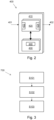
- FIG. 2 shows a simplified example of a control system 400 such as may be adapted in accordance with an embodiment of the invention.
- the control system 400 may comprises one or more controllers 410.
- the or each controller 410 can comprise a control unit or computational device having one or more electronic processors (for example, a microprocessor, a microcontroller, an application specific integrated circuit (ASIC), etc.), and may comprise a single control unit or computational device, or alternatively different functions of the or each controller 410 may be embodied in, or hosted in, different control units or computational devices.
- ASIC application specific integrated circuit
- controller As used herein, the term "controller,” “control unit,” or “computational device” will be understood to include a single controller, control unit, or computational device, and a plurality of controllers, control units, or computational devices collectively operating to provide the required control functionality.
- a set of instructions could be provided which, when executed, cause the controller 410 to implement the control techniques described herein (including some or all of the functionality required for the method described herein).
- the set of instructions could be embedded in said one or more electronic processors of the controller 410; or alternatively, the set of instructions could be provided as software to be executed in the controller 410.
- a first controller or control unit may be implemented in software run on one or more processors.
- One or more other controllers or control units may be implemented in software run on one or more processors, optionally the same one or more processors as the first controller or control unit. Other arrangements are also useful.
- the or each controller 410 comprises at least one electronic processor 420 having one or more electrical input(s) 422 for receiving one or more input signal(s) 401, such as those described above and one or more electrical output(s) 424 for outputting one or more output signal(s) 402, such as a switch signal to instruct the adjustable suspension as described above.
- the or each controller 410 further comprises at least one memory device 430 electrically coupled to the at least one electronic processor 420 and having instructions 440 stored therein.
- The, or each, electronic processor 420 may comprise any suitable electronic processor (for example, a microprocessor, a microcontroller, an ASIC, etc.) that is configured to execute electronic instructions.
- The, or each, electronic memory device 430 may comprise any suitable memory device and may store a variety of data, information, threshold value(s), lookup tables or other data structures, and/or instructions therein or thereon.
- the memory device 430 has information and instructions for software, firmware, programs, algorithms, scripts, applications, etc. stored therein or thereon that may govern all or part of the methodology described herein.
- the processor, or each, electronic processor 420 may access the memory device 430 and execute and/or use that or those instructions and information to carry out or perform some or all of the functionality and methodology describe herein.
- the at least one memory device 430 may comprise a computer-readable storage medium (for example a non-transitory or non-transient storage medium) that may comprise any mechanism for storing information in a form readable by a machine or electronic processors/computational devices, including, without limitation: a magnetic storage medium (for example floppy diskette); optical storage medium (for example CD-ROM); magneto optical storage medium; read only memory (ROM); random access memory (RAM); erasable programmable memory (for example EPROM ad EEPROM); flash memory; or electrical or other types of medium for storing such information/instructions.
- a computer-readable storage medium for example a non-transitory or non-transient storage medium
- a magnetic storage medium for example floppy diskette
- optical storage medium for example CD-ROM
- magneto optical storage medium for example CD-ROM
- ROM read only memory
- RAM random access memory
- EPROM ad EEPROM erasable programmable memory
- flash memory or electrical or other types of
- Example controllers 410 have been described comprising at least one electronic processor 420 configured to execute electronic instructions stored within at least one memory device 430, which when executed causes the electronic processor(s) 420 to carry out the method as hereinbefore described.
- the present invention is not limited to being implemented by way of programmable processing devices, and that at least some of, and in some embodiments all of, the functionality and or method steps of the present invention may equally be implemented by way of non-programmable hardware, such as by way of non-programmable ASIC, Boolean logic circuitry, etc.
- Figure 3 shows a method 700 in accordance with an embodiment of the invention.
- the method at S101, comprises receiving route data indicative of an expected route of the vehicle.
- the method comprises receiving map data comprising road type information for a road section of the expected route.
- the method comprises outputting a switch signal to instruct the adjustable suspension to switch between the two different configurations in dependence on the expected route and the road type information, before the vehicle reaches the road section. It will be appreciated that embodiments of the method may comprise execution configurations of the control system described above.
Landscapes
- Engineering & Computer Science (AREA)
- Mechanical Engineering (AREA)
- Automation & Control Theory (AREA)
- Chemical & Material Sciences (AREA)
- Combustion & Propulsion (AREA)
- Transportation (AREA)
- Vehicle Body Suspensions (AREA)
Description
- The present disclosure relates to a control system for an adjustable suspension of a vehicle, to an adjustable suspension, and to a vehicle comprising such an adjustable suspension. The present disclosure further relates to a method for controlling an adjustable suspension of a vehicle.
- Many modern cars have adjustable suspension systems that allow the user to change the driving characteristics of the car in accordance with his or her preferences. These preferences may for example depend on the driver's current mood, road quality or total load of the car in terms of luggage and passengers. Adjusting the suspension will often provide for variation in suspension stiffness. In some configurations, the suspension may provide a more comfortable driving experience. In other configurations, the car may be better suited for a sportier drive style, giving the driver a more direct feel of the road. Adjustment of the suspension system can also result in an effective lowering or raising of the car relative to its wheels and the road surface. On smoother roads and at higher speeds it may, for example, be advantageous to drive in a lowered configuration wherein the frontal area of the car is reduced and the car's energy efficiency is improved.
- In some more advanced suspension control systems, the suspension settings may be adapted automatically based on input signals such as vehicle speed or sensor signals from the suspension system, a steering wheel, or a gas pedal. Such automated systems may help the drivers to enjoy the possible benefits of an adjustable suspension system, without having to change any settings manually, thereby allowing them to pay more attention to the actual driving of the car and navigating through traffic. A disadvantage of such automated systems is, however, that they may struggle to promptly respond to changing circumstances. Adjusting the suspension settings takes time as well as energy. Consequently, the automated system cannot instantaneously and continuously react to every change of situation. When the automated adjustment system, based on the incoming sensor signals determines that, for example, the car slows down or the road surface gets rougher, it first has to make sure that this is not just a temporary variation. The resulting delay in may lead to discomfort for the driver.
- Document
US 2018/079272 A1 describes a method comprising receiving, at a control system of a vehicle, a road profile for a road at a particular location, the road profile indicating a road condition of the road at the particular location. The method also includes determining that the vehicle is approaching the road at the particular location. The method further includes adjusting an active suspension system of the vehicle in response to a determination that the vehicle is approaching the road at the particular location. - Document
FR 3090500 A1 - Document
US 2005/090956 A1 describes how when a vehicle approaches a corner, a microprocessor, responsive to a determination that a detected degree of roughness of the road surface corresponds to the most moderate roughness, sets the damping force for the vehicle suspension units, on the basis of the detected degree of roughness, vehicle speed and a radius of curvature and corner information from a navigation system. In the case of a determination that the detected degree of roughness does not correspond to the most moderate roughness, a damping level is set on the basis of the detected degree of roughness, vehicle speed and radius of curvature. - Document
WO 2013/004764 A1 describes a vehicle control system for at least one vehicle subsystem of a vehicle. The vehicle control system comprises a subsystem controller for initiating control of the or each of the vehicle subsystems in a selected one of a plurality of different subsystem control modes, each of which corresponds to one or more different driving conditions for the vehicle. Evaluation means are provided for evaluating one or more driving condition indicators to determine the extent to which each of the subsystem control modes is appropriate and for providing an output to the subsystem controller that is indicative of the control mode which is most appropriate. This may be an evaluation means for calculating the probability that the or each of the subsystem control modes is appropriate. Automatic control means may be operable in an automatic response mode to select an appropriate one of the subsystem control modes in dependence on the output. - It is an aim of the present invention to address one or more of the disadvantages associated with prior art.
- Aspects and embodiments of the invention provide a vehicle comprising an adjustable suspension system comprising a control system, a method for controlling an adjustable suspension of a vehicle, and a non-transitory computer readable medium.
- According to an aspect of the present invention there is provided a vehicle comprising an adjustable suspension system operable in at least two different configurations, the adjustable suspension comprising a control system. The control system comprises one or more controllers configured to receive route data indicative of an expected route of the vehicle, receive map data comprising road type information for a road section of the expected route, and output a switch signal to instruct the adjustable suspension to switch between the two different configurations in dependence on the expected route and the road type information, before the vehicle reaches the road section. The control system is configured to estimate a stable stretch of road indicative of a length of road wherein, after an initial switching between the two configurations, the suspension remains in the switched-to configuration, and to output the switch signal in dependence on the estimated stable stretch of road.
- By taking into account the expected route of the vehicle and the to be expected road type, the control system is capable of predicting the optimal configuration for the vehicle suspension in the near future. This prior knowledge of the road surface that the vehicle will be on allows the control system to start adjusting the configuration of the adjustable suspension already before a new and different road section is reached. This brings the important advantage that the switching between two different configurations can already be fully completed at the moment the car reaches the new road section. On top of that, the control system according to the invention can use its knowledge about the vehicle's expected trajectory and the corresponding road type information to determine when switching to a different suspension configurations will only be of limited benefit because of an upcoming subsequent change of circumstances. In such situations, the control system may now decide that it is not worth adjusting the suspension settings at all.
- In an embodiment, the one or more controllers may collectively comprise at least one electronic processor having an electrical input for receiving the route data and the map data; and at least one memory device electrically coupled to the at least one electronic processor and having instructions stored therein, and wherein the at least one electronic processor is configured to access the at least one memory device and execute the instructions thereon so as to output the switch signal to instruct the suspension.
- In an embodiment, the two different configurations comprise a first configuration, wherein the adjustable suspension is adapted for driving on a rougher road surface, and
a second configuration, wherein the vehicle is configured for reduced drag on a smoother road surface. In the first configuration the suspension may be adapted for more comfortable driving. It is noted that rougher and smoother are relative terms, used only to indicate that the first configuration is provided for use on road sections that are generally more rough than the road sections for which the second configuration is more suitable. However, since the optimal settings may depend on many more factors than just the surface roughness of the road, it is quite well possible that sometimes the first configuration is preferred for a road section where usually the second configuration is more suitable, and vice versa. As an example, reduced drag may be obtained by adjusting the suspension system in such a way as to lower the vehicle body relative to its wheels, and thus the road surface, in order to reduce its frontal area. In a more advanced embodiment, three or more different configurations may be available for a further improved adaptation to different driving conditions and driving styles, while minimising drag. Alternatively, the suspension system may be continuously adaptable in response to the various input parameters and user preferences. - According to the invention, the control system is configured to estimate a stable stretch and to output the switch signal in dependence on the estimated stable stretch. The estimated stable stretch is indicative of a length of road wherein, after an initial switching between the two configurations, the suspension remains in the switched-to configuration.
- By making such estimations, it becomes possible to, for example, balance the amount of time and energy needed for switching to a different configuration against the total benefit that may be expected from doing so, before the control system needs to switch back to its original configuration.
- The control system may be configured to determine whether to output the switch signal to instruct the adjustable suspension to switch between the two different configurations in dependence on a comparison of the stable stretch of road to a threshold.
- In a further embodiment, the control system may be configured to estimate an energy gain resulting from switching between the two different configurations and to instruct the suspension to switch between the two different configurations in dependence on the estimated energy gain. For example, lowering the vehicle position may only lead to substantial energy savings when the vehicle is expected to drive above a certain speed, or when it can do so for a substantial amount of time. The expected energy gain may be balanced against the expected energy expenditure for switching between the different configurations.
- Optionally, the control system is configured to receive at least one of: an expected driving speed of the vehicle when driving on the road section; traffic information for the road section; weather information for the road section; a planned route from a navigation system; historic travel data relating to the vehicle; and historic travel data relating to a user of the vehicle, and to instruct the suspension to switch between the two different configurations in dependence on at least one of: the expected driving speed, the traffic information, the weather information, the planned route, and the historic travel data. Other information that may be taken into account is, for example, information about traffic density and expected delays. Traffic information may include information about, for example temporary road closures.
- The expected route may, for example, be determined based on a planned route from a navigation system or from historic travel data relating to the vehicle or the user of the vehicle. The navigation system may be built-in into the car or running on a mobile phone of the driver or one of the passengers.
- The road type information may comprise all kinds of information that could be relevant for determining the optimal vehicle suspension settings. For example, the road type information may include one or more of a speed limit, an average driving speed, a road quality indicator, and pothole information for the respective road section. Preferably, such more static information is combined with more dynamic information such as current traffic and weather information. For example, traffic information may indicate that the vehicle is likely to be able to drive at the speed limit, or that it will not be possible to drive at the average speed that is normally expected at that road section. Rain, snow, wind and other weather conditions may influence driving conditions and the ideal suspension configuration too.
- According to another aspect of the invention, a method is provided for controlling an adjustable suspension of a vehicle, the adjustable suspension being operable in at least two different configurations. The method comprises receiving route data indicative of an expected route of the vehicle, receiving map data comprising road type information for a road section of the expected route, outputting a switch signal to instruct the adjustable suspension to switch between the two different configurations in dependence on the expected route and the road type information, before the vehicle reaches the road section, estimating a stable stretch of road indicative of a length of road; wherein, after an initial switching between the two configurations, the suspension can remain in the switched-to configuration; and, outputting the switch signal in dependence on the estimated stable stretch of road.
- The two different configurations may comprise: a first configuration, wherein the adjustable suspension is adapted for driving on a rougher road surface, and a second configuration, wherein the vehicle is configured for reduced drag on a smoother road surface.
- The method may further comprise determining whether to output the switch signal to instruct the adjustable suspension to switch between the two different configurations in dependence on a comparison of the stable stretch of road to a threshold.
- The method may further comprise estimating an energy gain resulting from switching between the two different configurations and wherein the instructing the suspension to switch between the two different configurations is performed in dependence on the estimated energy gain.
- A non-transitory computer readable medium is provided, comprising computer readable instructions to cause the vehicle described to execute this method.
- One or more embodiments of the invention will now be described, by way of example only, with reference to the accompanying drawings, in which:
-
Figure 1 schematically shows a vehicle with a vehicle suspension control system according to the invention; -
Figure 2 shows a simplified example of a control system such as may be adapted in accordance with an embodiment of the invention; and -
Figure 3 shows a method in accordance with an embodiment of the invention. - A control system for a vehicle in accordance with an embodiment of the present invention is described herein with reference to the accompanying figures.
-
Figure 1 schematically shows avehicle 100 with a vehiclesuspension control system 400 according to the invention. Thevehicle 100 has afront axle 101 and arear axle 102, each supporting a left and aright wheel 103. It is noted that thevehicle 100 shown here is just one example of a practical embodiment in which thecontrol system 400 of the invention can be of benefit. Thecontrol system 400 of the invention can be of similar benefit in other vehicles with anadjustable suspension mechanism 104, such as tracked vehicles or vehicles with fewer or more than four wheels. In an embodiment the adjustable suspension system comprises ansuspension actuator 104 that is operable to adjust a configuration of the suspension system and asuspension sensor 105 that monitors one or more operational aspects of the suspension system, such as the suspension system configuration, vibrations or forces working on (parts of) the suspension system. Theactuator 104 may, for example, be configured to adjust damping characteristics or a stiffness of a suspension spring, a range of movement for the suspension, or a relative position of (parts of) the suspension system relative to thewheel 103 and/or a chassis of thevehicle 100. Theactuator 104 may, for example, be a mechanical, a hydraulic or a pneumatic actuator, or use a combination of such technologies. Theactuator 104 is electronically controlled by control signals coming from the vehiclesuspension control system 400. Sensor signals from thesuspension sensors 105 are sent to controlsystem 400. - The vehicle suspension may, for example, be configured in response to
user input 150, feedback from thesuspension sensors 105, speed sensors, rain sensors, temperature sensors, and real-time data obtained from camera images. While such data can be useful for adapting the suspension configuration to changes in road quality, traffic situation or user preference, it has the disadvantages that the control response may be delayed with respect to the detected change and that energy may be wasted when reacting to changes that later turn out to be very temporary. To further improve the suspension control, the now proposedsuspension control system 400 uses predictive information that allows the control system to initiate changes to the configuration of the suspension system, already before the vehicle reaches the different road type, traffic situation or vehicle speed. Thus, any delays resulting from the control system's reaction time or from the time needed to change the configuration of the suspension system are effectively reduced or fully eliminated. - Examples of such predictive information are
route data 110 from a built-inroute navigation system 115 or from a route navigation system running on themobile phone 140 of the driver or another passenger. When combined with road type information from amap data source 120, thecontrol system 400 knows what roads thevehicle 100 is going to drive on, when it's going to do so and what road surface to expect there. Based on that information, thecontrol system 400 can then start to adjust the suspension configuration ahead of actually reaching a road section where a different configuration would be useful. This will allow for a smoother transition between different road sections and a more comfortable ride during larger portions of the total ride. - The road type information may comprise all kinds of information that could be relevant for determining the optimal vehicle suspension settings. For example, the road type information may include a speed limit or an average driving speed for similar vehicles on the same road. The road type information may further comprises, for example, a road quality indicator representative of an average smoothness of the road surface and/or of an average or local variability of such smoothness. Pothole information may indicate a number, diameter and/or depth of potholes in the respective road section or in specific parts or lanes of that road sections. Optionally, such road type information may additionally be used by an automated driving assistance system to steer the
vehicle 100 to those lanes where the current suspension configuration provides the most comfortable driving experience. - Most of this type of road type information will be off a static nature, but it may be updated regularly to deal with changes that occur over time. The map data may come from an external service provider, for example via a mobile Internet connection. Some or all the data may be stored locally on a
local storage medium 160.Such data storage 160 may be shared with or part of theroute navigation system 115, which already includes data about where roads are located and some basic information about these roads (for example but not limited to: speed limit; number of lanes and maximum vehicle heights). Thedata storage 160 may be part of thevehicle 100 itself, or it may be stored on the mobile phone of the driver or one of the passengers. - Optionally, the externally provided data is supplemented with data derived from a vehicle camera or other vehicle sensors to obtain an even more accurate picture of the local road quality. Any road information data obtained by sensors on the
vehicle 100 may be uploaded to the external service provider to also keep the externally provided data up to date. Thecontrol system 400 may be able to combine data from several data sources. For example, a taxi may make use of thecontrol system 400 based on data stored in his own navigation system and updated by an external service provider. When the taxi drives a passenger to an area where the user has recently driven himself, relevant data from the user's phone may be used to update the road information data stored in the taxi. Alternatively, the passenger data is only used by the taxi for improved suspension control during this one taxi ride. - Preferably, the more static road type information is combined with more dynamic information such as current traffic and
weather information 130. For example, traffic information may indicate that thevehicle 100 is likely to be able to drive at the speed limit, or that it will not be possible to drive at the average speed that is normally expected at that road section. Rain, snow, wind, and other weather conditions may influence driving conditions and the ideal suspension configuration too. Traffic andweather information 130 is obtained from an external service provider, for example, via the Internet. The external service provider delivering the traffic andweather information 130 may be the same provider that provides the road type information too, - Adjusting the suspension system can be performed in a variety of ways. In some configurations, the suspension may provide a more comfortable driving experience. In other configurations, the
vehicle 100 may be better suited for a sportier drive style, giving the driver a more direct feel of the road. Adjustment of the suspension system can also result in an effective lowering or raising of thevehicle 100 relative to itswheels 103 and the road surface. On smoother roads and at higher speeds it may, for example, be advantageous to drive in a lowered configuration wherein the frontal area of thevehicle 100 is reduced and its energy efficiency is improved. - When, for example, driving towards a smooth and empty highway, the
control system 400 may start to lower thevehicle 100 already before thevehicle 100 is driving on that highway. However, moving between the lower and the raised configurations takes time and energy. If the road quality is expected to be much lower soon, a traffic jam is near, or the vehicle is expected to leave the highway at the first exit, it may be preferred to not switch to the lowered configuration. In such cases, the possible increase in energy efficiency may not be enough to fully compensate for the energy cost of switching the configuration of the suspension twice (once to lower the vehicle chassis, and once to return to the raised configuration). Thecontrol system 400 may thus use its knowledge about the vehicle's expected trajectory and the corresponding road type information to determine when switching to a different suspension configuration will be useful and when it will only be of limited benefit. In such situations of limited or no benefit, thecontrol system 400 may decide not to adjust the suspension settings at all. - To determine whether it will be beneficial to change the suspension configuration, the
control system 400 is configured to estimate a stable stretch. The estimated stable stretch is indicative of a length of road wherein, after an initial switching between the two configurations, the suspension can remain in the switched-to configuration. For deciding whether to change the suspension configuration, the stable stretch may be compared to a simple fixed threshold, or a threshold that depends on variables such as the vehicle speed or current wind speeds. Preferably, thecontrol system 400 is further configured to estimate an energy gain resulting from switching between the two different configurations. By making such estimations, it becomes possible to, for example, balance the amount of time and energy needed for switching to a different configuration against the total benefit that may be expected from doing so, before thecontrol system 400 needs to switch back to its original configuration. - Part of the functionality of the
suspension control system 400 may be realised remotely. While the actual control of the adjustable suspension system will typically be carried out by an on-board control system, the processing of the input data may be performed by a cloud service. For example, the map data comprising the road type information does not need to reach theactual vehicle 100. Thevehicle 100 may submit its route information to the cloud service and receive the appropriate suspension settings in return. Of course, the vehicle'snavigation system 115 may rely on a cloud based service too, in which case the on board share of the suspension control system activity may be limited to relaying sensor and camera data to the cloud service and receiving specific instruction for adjusting the suspension system in return. -
Figure 2 shows a simplified example of acontrol system 400 such as may be adapted in accordance with an embodiment of the invention. Thecontrol system 400 may comprises one ormore controllers 410. It is to be understood that the or eachcontroller 410 can comprise a control unit or computational device having one or more electronic processors (for example, a microprocessor, a microcontroller, an application specific integrated circuit (ASIC), etc.), and may comprise a single control unit or computational device, or alternatively different functions of the or eachcontroller 410 may be embodied in, or hosted in, different control units or computational devices. As used herein, the term "controller," "control unit," or "computational device" will be understood to include a single controller, control unit, or computational device, and a plurality of controllers, control units, or computational devices collectively operating to provide the required control functionality. A set of instructions could be provided which, when executed, cause thecontroller 410 to implement the control techniques described herein (including some or all of the functionality required for the method described herein). The set of instructions could be embedded in said one or more electronic processors of thecontroller 410; or alternatively, the set of instructions could be provided as software to be executed in thecontroller 410. A first controller or control unit may be implemented in software run on one or more processors. One or more other controllers or control units may be implemented in software run on one or more processors, optionally the same one or more processors as the first controller or control unit. Other arrangements are also useful. - In the example illustrated in
Figure 2 , the or eachcontroller 410 comprises at least oneelectronic processor 420 having one or more electrical input(s) 422 for receiving one or more input signal(s) 401, such as those described above and one or more electrical output(s) 424 for outputting one or more output signal(s) 402, such as a switch signal to instruct the adjustable suspension as described above. The or eachcontroller 410 further comprises at least onememory device 430 electrically coupled to the at least oneelectronic processor 420 and havinginstructions 440 stored therein. - The, or each,
electronic processor 420 may comprise any suitable electronic processor (for example, a microprocessor, a microcontroller, an ASIC, etc.) that is configured to execute electronic instructions. The, or each,electronic memory device 430 may comprise any suitable memory device and may store a variety of data, information, threshold value(s), lookup tables or other data structures, and/or instructions therein or thereon. In an embodiment, thememory device 430 has information and instructions for software, firmware, programs, algorithms, scripts, applications, etc. stored therein or thereon that may govern all or part of the methodology described herein. The processor, or each,electronic processor 420 may access thememory device 430 and execute and/or use that or those instructions and information to carry out or perform some or all of the functionality and methodology describe herein. - The at least one
memory device 430 may comprise a computer-readable storage medium (for example a non-transitory or non-transient storage medium) that may comprise any mechanism for storing information in a form readable by a machine or electronic processors/computational devices, including, without limitation: a magnetic storage medium (for example floppy diskette); optical storage medium (for example CD-ROM); magneto optical storage medium; read only memory (ROM); random access memory (RAM); erasable programmable memory (for example EPROM ad EEPROM); flash memory; or electrical or other types of medium for storing such information/instructions. -
Example controllers 410 have been described comprising at least oneelectronic processor 420 configured to execute electronic instructions stored within at least onememory device 430, which when executed causes the electronic processor(s) 420 to carry out the method as hereinbefore described. However, it is contemplated that the present invention is not limited to being implemented by way of programmable processing devices, and that at least some of, and in some embodiments all of, the functionality and or method steps of the present invention may equally be implemented by way of non-programmable hardware, such as by way of non-programmable ASIC, Boolean logic circuitry, etc. -
Figure 3 shows amethod 700 in accordance with an embodiment of the invention. In an embodiment of the invention the method, at S101, comprises receiving route data indicative of an expected route of the vehicle. At S102 the method comprises receiving map data comprising road type information for a road section of the expected route. At S103 the method comprises outputting a switch signal to instruct the adjustable suspension to switch between the two different configurations in dependence on the expected route and the road type information, before the vehicle reaches the road section. It will be appreciated that embodiments of the method may comprise execution configurations of the control system described above.
Claims (10)
- A vehicle (100) comprising an adjustable suspension system operable in at least two different configurations, the adjustable suspension comprising a control system (400), comprising one or more controller (410) configured to:receive route data indicative of an expected route of the vehicle (100);receive map data comprising road type information for a road section of the expected route; andoutput a switch signal to instruct the adjustable suspension to switch between the two different configurations in dependence on the expected route and the road type information, before the vehicle (100) reaches the road section,wherein the control system (400) is configured to estimate a stable stretch of road indicative of a length of road wherein, after an initial switching between the two configurations, the suspension remains in the switched-to configuration, and to output the switch signal in dependence on the estimated stable stretch of road.
- A vehicle (100) according to claim 1, wherein the two different configurations comprise:a first configuration, wherein the adjustable suspension is adapted for driving on a rougher road surface; anda second configuration, wherein the vehicle (100) is configured for reduced drag on a smoother road surface.
- A vehicle (100) according to claim 1 or 2, wherein the control system (400) is configured to determine whether to output the switch signal to instruct the adjustable suspension to switch between the two different configurations in dependence on a comparison of the stable stretch of road to a threshold.
- A vehicle (100) according to any of the preceding claims, wherein the control system (400) is configured to estimate an energy gain resulting from switching between the two different configurations and to instruct the suspension to switch between the two different configurations in dependence on the estimated energy gain.
- A vehicle (100) according to any of the preceding claims, wherein the control system (400) is configured to receive at least one of:an expected driving speed of the vehicle (100) when driving on the road section;traffic information for the road section;weather information for the road section;a planned route from a navigation system (115);historic travel data relating to the vehicle (100); andhistoric travel data relating to a user of the vehicle (100),and to instruct the suspension to switch between the two different configurations in dependence on at least one of:the expected driving speed;the traffic information;the weather information;the planned route; andthe historic travel data.
- A method for controlling an adjustable suspension of a vehicle (100), the adjustable suspension being operable in at least two different configurations, the method comprising:receiving route data indicative of an expected route of the vehicle (100);receiving map data comprising road type information for a road section of the expected route;outputting a switch signal to instruct the adjustable suspension to switch between the two different configurations in dependence on the expected route and the road type information, before the vehicle (100) reaches the road section;estimating a stable stretch of road indicative of a length of road; wherein, after an initial switching between the two configurations, the suspension can remain in the switched-to configuration; and,outputting the switch signal in dependence on the estimated stable stretch of road.
- A method according to claim 6, wherein the two different configurations comprise:a first configuration, wherein the adjustable suspension is adapted for driving on a rougher road surface, anda second configuration, wherein the vehicle (100) is configured for reduced drag on a smoother road surface.
- A method according to claim 6 or 7, comprising determining whether to output the switch signal to instruct the adjustable suspension to switch between the two different configurations in dependence on a comparison of the stable stretch of road to a threshold.
- A method according to any of claims 6 to 8, comprising estimating an energy gain resulting from switching between the two different configurations and wherein the instructing the suspension to switch between the two different configurations is performed in dependence on the estimated energy gain.
- A non-transitory computer readable medium comprising computer readable instructions to cause the vehicle (100) of claim 1 to execute the method of any of claims 6 to 9.
Applications Claiming Priority (2)
| Application Number | Priority Date | Filing Date | Title |
|---|---|---|---|
| GB2013059.7A GB2598147B (en) | 2020-08-21 | 2020-08-21 | Vehicle suspension control system |
| PCT/EP2021/073058 WO2022038231A1 (en) | 2020-08-21 | 2021-08-19 | Vehicle suspension control system |
Publications (2)
| Publication Number | Publication Date |
|---|---|
| EP4200146A1 EP4200146A1 (en) | 2023-06-28 |
| EP4200146B1 true EP4200146B1 (en) | 2025-04-09 |
Family
ID=72660732
Family Applications (1)
| Application Number | Title | Priority Date | Filing Date |
|---|---|---|---|
| EP21765642.0A Active EP4200146B1 (en) | 2020-08-21 | 2021-08-19 | Vehicle suspension control system |
Country Status (4)
| Country | Link |
|---|---|
| US (1) | US12138979B2 (en) |
| EP (1) | EP4200146B1 (en) |
| GB (1) | GB2598147B (en) |
| WO (1) | WO2022038231A1 (en) |
Families Citing this family (6)
| Publication number | Priority date | Publication date | Assignee | Title |
|---|---|---|---|---|
| US12403740B2 (en) * | 2021-09-17 | 2025-09-02 | Rivian Ip Holdings, Llc | Active suspension damping |
| CN115122848A (en) * | 2022-07-13 | 2022-09-30 | 亿咖通(湖北)技术有限公司 | Air suspension regulation and control method, device, equipment and storage medium |
| CN115384615B (en) * | 2022-10-10 | 2024-05-07 | 南京林业大学 | A road feel control method for a steer-by-wire system considering driving style |
| CN115871402A (en) * | 2022-11-30 | 2023-03-31 | 重庆长安汽车股份有限公司 | A composite active suspension control method, device, equipment, vehicle and storage medium |
| US12594806B2 (en) * | 2023-03-01 | 2026-04-07 | Tesla, Inc. | Vehicle suspension control system |
| CN116278571A (en) * | 2023-03-29 | 2023-06-23 | 阿维塔科技(重庆)有限公司 | Vehicle control method, device, device and storage medium |
Citations (1)
| Publication number | Priority date | Publication date | Assignee | Title |
|---|---|---|---|---|
| WO2013004764A1 (en) * | 2011-07-04 | 2013-01-10 | Land Rover | Vehicle control system and method for controlling a vehicle |
Family Cites Families (8)
| Publication number | Priority date | Publication date | Assignee | Title |
|---|---|---|---|---|
| JP2005112041A (en) | 2003-10-03 | 2005-04-28 | Aisin Aw Co Ltd | Suspension control system and suspension control method for vehicle |
| GB2511830B (en) * | 2013-03-14 | 2015-12-30 | Jaguar Land Rover Ltd | Ride height control unit and method |
| EP4450845A3 (en) * | 2013-03-15 | 2025-01-01 | ClearMotion, Inc. | Active vehicle suspension improvements |
| US10315481B2 (en) * | 2015-11-05 | 2019-06-11 | Ford Global Technologies, Llc | Systems and methods for vehicle dynamics assignment |
| US9889716B2 (en) * | 2016-02-03 | 2018-02-13 | Ford Global Technologies, Llc | Roadway-crossing-anomaly detection system and method |
| US20180079272A1 (en) * | 2016-09-20 | 2018-03-22 | Apple Inc. | Motion minimization systems and methods |
| US11285773B1 (en) * | 2018-09-12 | 2022-03-29 | Apple Inc. | Control system |
| FR3090500B1 (en) * | 2018-12-21 | 2021-06-11 | Psa Automobiles Sa | TWO OPERATING MODES PNEUMATIC SUSPENSION WITH PARALLEL AIR CELLS |
-
2020
- 2020-08-21 GB GB2013059.7A patent/GB2598147B/en active Active
-
2021
- 2021-08-19 WO PCT/EP2021/073058 patent/WO2022038231A1/en not_active Ceased
- 2021-08-19 US US18/042,318 patent/US12138979B2/en active Active
- 2021-08-19 EP EP21765642.0A patent/EP4200146B1/en active Active
Patent Citations (1)
| Publication number | Priority date | Publication date | Assignee | Title |
|---|---|---|---|---|
| WO2013004764A1 (en) * | 2011-07-04 | 2013-01-10 | Land Rover | Vehicle control system and method for controlling a vehicle |
Also Published As
| Publication number | Publication date |
|---|---|
| GB2598147A (en) | 2022-02-23 |
| US12138979B2 (en) | 2024-11-12 |
| WO2022038231A1 (en) | 2022-02-24 |
| GB202013059D0 (en) | 2020-10-07 |
| GB2598147B (en) | 2023-03-22 |
| US20230311606A1 (en) | 2023-10-05 |
| EP4200146A1 (en) | 2023-06-28 |
Similar Documents
| Publication | Publication Date | Title |
|---|---|---|
| US12138979B2 (en) | Vehicle suspension control system | |
| JP4446978B2 (en) | Vehicle driving force control device | |
| CN101152842B (en) | ride control device | |
| JP5168421B2 (en) | Driving assistance device | |
| US9969394B2 (en) | Distance regulating system, motor vehicle and computer program product | |
| JP4873047B2 (en) | Travel control device | |
| CN102656081A (en) | Arrangement and method for optimizing the position of at least one air deflector | |
| US11738749B2 (en) | Methods, systems, and apparatuses for scenario-based path and intervention adaptation for lane-keeping assist systems | |
| JP2009061878A (en) | Travel control device | |
| JP2016199252A (en) | Intelligent gap setting for adaptive cruise control | |
| JP2005112041A (en) | Suspension control system and suspension control method for vehicle | |
| CN101885331A (en) | Be used to control the method and apparatus of active vehicle subsystem | |
| US11872988B2 (en) | Method and system to adapt overtake decision and scheduling based on driver assertions | |
| CN117222563A (en) | Method and driver assistance system for supporting a motor vehicle when performing a turn | |
| US20240375653A1 (en) | Control Device and Method for Controlling a Predictive Cruise Control | |
| JP7066463B2 (en) | Driving support system and vehicle control method | |
| JP2006036159A (en) | Vehicle travel control device | |
| KR102562411B1 (en) | Method for assisting a driver of an ego-vehicle when driving through a curve lying ahead | |
| GB2614825A (en) | Vehicle suspension control system | |
| JP7675314B2 (en) | Vehicle control device, vehicle control method, and vehicle control system | |
| JP7351076B2 (en) | Electric vehicle control method and electric vehicle control device | |
| JP4069765B2 (en) | Vehicle travel control device | |
| US20210206370A1 (en) | Driving Through and Leaving a Roundabout in an Automatic Longitudinal Guidance Operation | |
| JP7647639B2 (en) | Vehicle control device | |
| CN118163780A (en) | Method and system for vehicle control in degraded lane awareness |
Legal Events
| Date | Code | Title | Description |
|---|---|---|---|
| STAA | Information on the status of an ep patent application or granted ep patent |
Free format text: STATUS: UNKNOWN |
|
| STAA | Information on the status of an ep patent application or granted ep patent |
Free format text: STATUS: THE INTERNATIONAL PUBLICATION HAS BEEN MADE |
|
| PUAI | Public reference made under article 153(3) epc to a published international application that has entered the european phase |
Free format text: ORIGINAL CODE: 0009012 |
|
| STAA | Information on the status of an ep patent application or granted ep patent |
Free format text: STATUS: REQUEST FOR EXAMINATION WAS MADE |
|
| 17P | Request for examination filed |
Effective date: 20230321 |
|
| AK | Designated contracting states |
Kind code of ref document: A1 Designated state(s): AL AT BE BG CH CY CZ DE DK EE ES FI FR GB GR HR HU IE IS IT LI LT LU LV MC MK MT NL NO PL PT RO RS SE SI SK SM TR |
|
| DAV | Request for validation of the european patent (deleted) | ||
| DAX | Request for extension of the european patent (deleted) | ||
| STAA | Information on the status of an ep patent application or granted ep patent |
Free format text: STATUS: EXAMINATION IS IN PROGRESS |
|
| 17Q | First examination report despatched |
Effective date: 20240402 |
|
| P01 | Opt-out of the competence of the unified patent court (upc) registered |
Free format text: CASE NUMBER: APP_33630/2024 Effective date: 20240605 |
|
| GRAP | Despatch of communication of intention to grant a patent |
Free format text: ORIGINAL CODE: EPIDOSNIGR1 |
|
| STAA | Information on the status of an ep patent application or granted ep patent |
Free format text: STATUS: GRANT OF PATENT IS INTENDED |
|
| INTG | Intention to grant announced |
Effective date: 20241106 |
|
| GRAS | Grant fee paid |
Free format text: ORIGINAL CODE: EPIDOSNIGR3 |
|
| GRAA | (expected) grant |
Free format text: ORIGINAL CODE: 0009210 |
|
| STAA | Information on the status of an ep patent application or granted ep patent |
Free format text: STATUS: THE PATENT HAS BEEN GRANTED |
|
| AK | Designated contracting states |
Kind code of ref document: B1 Designated state(s): AL AT BE BG CH CY CZ DE DK EE ES FI FR GB GR HR HU IE IS IT LI LT LU LV MC MK MT NL NO PL PT RO RS SE SI SK SM TR |
|
| REG | Reference to a national code |
Ref country code: GB Ref legal event code: FG4D |
|
| REG | Reference to a national code |
Ref country code: CH Ref legal event code: EP |
|
| REG | Reference to a national code |
Ref country code: DE Ref legal event code: R096 Ref document number: 602021028966 Country of ref document: DE |
|
| REG | Reference to a national code |
Ref country code: IE Ref legal event code: FG4D |
|
| REG | Reference to a national code |
Ref country code: NL Ref legal event code: MP Effective date: 20250409 |
|
| PG25 | Lapsed in a contracting state [announced via postgrant information from national office to epo] |
Ref country code: NL Free format text: LAPSE BECAUSE OF FAILURE TO SUBMIT A TRANSLATION OF THE DESCRIPTION OR TO PAY THE FEE WITHIN THE PRESCRIBED TIME-LIMIT Effective date: 20250409 |
|
| REG | Reference to a national code |
Ref country code: AT Ref legal event code: MK05 Ref document number: 1783239 Country of ref document: AT Kind code of ref document: T Effective date: 20250409 |
|
| PG25 | Lapsed in a contracting state [announced via postgrant information from national office to epo] |
Ref country code: PT Free format text: LAPSE BECAUSE OF FAILURE TO SUBMIT A TRANSLATION OF THE DESCRIPTION OR TO PAY THE FEE WITHIN THE PRESCRIBED TIME-LIMIT Effective date: 20250811 Ref country code: ES Free format text: LAPSE BECAUSE OF FAILURE TO SUBMIT A TRANSLATION OF THE DESCRIPTION OR TO PAY THE FEE WITHIN THE PRESCRIBED TIME-LIMIT Effective date: 20250409 Ref country code: FI Free format text: LAPSE BECAUSE OF FAILURE TO SUBMIT A TRANSLATION OF THE DESCRIPTION OR TO PAY THE FEE WITHIN THE PRESCRIBED TIME-LIMIT Effective date: 20250409 |
|
| PGFP | Annual fee paid to national office [announced via postgrant information from national office to epo] |
Ref country code: DE Payment date: 20250820 Year of fee payment: 5 |
|
| REG | Reference to a national code |
Ref country code: LT Ref legal event code: MG9D |
|
| PG25 | Lapsed in a contracting state [announced via postgrant information from national office to epo] |
Ref country code: NO Free format text: LAPSE BECAUSE OF FAILURE TO SUBMIT A TRANSLATION OF THE DESCRIPTION OR TO PAY THE FEE WITHIN THE PRESCRIBED TIME-LIMIT Effective date: 20250709 Ref country code: GR Free format text: LAPSE BECAUSE OF FAILURE TO SUBMIT A TRANSLATION OF THE DESCRIPTION OR TO PAY THE FEE WITHIN THE PRESCRIBED TIME-LIMIT Effective date: 20250710 |
|
| PG25 | Lapsed in a contracting state [announced via postgrant information from national office to epo] |
Ref country code: PL Free format text: LAPSE BECAUSE OF FAILURE TO SUBMIT A TRANSLATION OF THE DESCRIPTION OR TO PAY THE FEE WITHIN THE PRESCRIBED TIME-LIMIT Effective date: 20250409 |
|
| PG25 | Lapsed in a contracting state [announced via postgrant information from national office to epo] |
Ref country code: BG Free format text: LAPSE BECAUSE OF FAILURE TO SUBMIT A TRANSLATION OF THE DESCRIPTION OR TO PAY THE FEE WITHIN THE PRESCRIBED TIME-LIMIT Effective date: 20250409 |
|
| PGFP | Annual fee paid to national office [announced via postgrant information from national office to epo] |
Ref country code: GB Payment date: 20250820 Year of fee payment: 5 |
|
| PG25 | Lapsed in a contracting state [announced via postgrant information from national office to epo] |
Ref country code: HR Free format text: LAPSE BECAUSE OF FAILURE TO SUBMIT A TRANSLATION OF THE DESCRIPTION OR TO PAY THE FEE WITHIN THE PRESCRIBED TIME-LIMIT Effective date: 20250409 |
|
| PG25 | Lapsed in a contracting state [announced via postgrant information from national office to epo] |
Ref country code: AT Free format text: LAPSE BECAUSE OF FAILURE TO SUBMIT A TRANSLATION OF THE DESCRIPTION OR TO PAY THE FEE WITHIN THE PRESCRIBED TIME-LIMIT Effective date: 20250409 |
|
| PGFP | Annual fee paid to national office [announced via postgrant information from national office to epo] |
Ref country code: FR Payment date: 20250828 Year of fee payment: 5 |
|
| PG25 | Lapsed in a contracting state [announced via postgrant information from national office to epo] |
Ref country code: RS Free format text: LAPSE BECAUSE OF FAILURE TO SUBMIT A TRANSLATION OF THE DESCRIPTION OR TO PAY THE FEE WITHIN THE PRESCRIBED TIME-LIMIT Effective date: 20250709 |
|
| PG25 | Lapsed in a contracting state [announced via postgrant information from national office to epo] |
Ref country code: IS Free format text: LAPSE BECAUSE OF FAILURE TO SUBMIT A TRANSLATION OF THE DESCRIPTION OR TO PAY THE FEE WITHIN THE PRESCRIBED TIME-LIMIT Effective date: 20250809 |
|
| PG25 | Lapsed in a contracting state [announced via postgrant information from national office to epo] |
Ref country code: LV Free format text: LAPSE BECAUSE OF FAILURE TO SUBMIT A TRANSLATION OF THE DESCRIPTION OR TO PAY THE FEE WITHIN THE PRESCRIBED TIME-LIMIT Effective date: 20250409 |
|
| REG | Reference to a national code |
Ref country code: DE Ref legal event code: R097 Ref document number: 602021028966 Country of ref document: DE |
|
| PG25 | Lapsed in a contracting state [announced via postgrant information from national office to epo] |
Ref country code: SM Free format text: LAPSE BECAUSE OF FAILURE TO SUBMIT A TRANSLATION OF THE DESCRIPTION OR TO PAY THE FEE WITHIN THE PRESCRIBED TIME-LIMIT Effective date: 20250409 Ref country code: DK Free format text: LAPSE BECAUSE OF FAILURE TO SUBMIT A TRANSLATION OF THE DESCRIPTION OR TO PAY THE FEE WITHIN THE PRESCRIBED TIME-LIMIT Effective date: 20250409 |
|
| PG25 | Lapsed in a contracting state [announced via postgrant information from national office to epo] |
Ref country code: CZ Free format text: LAPSE BECAUSE OF FAILURE TO SUBMIT A TRANSLATION OF THE DESCRIPTION OR TO PAY THE FEE WITHIN THE PRESCRIBED TIME-LIMIT Effective date: 20250409 |
|
| PG25 | Lapsed in a contracting state [announced via postgrant information from national office to epo] |
Ref country code: EE Free format text: LAPSE BECAUSE OF FAILURE TO SUBMIT A TRANSLATION OF THE DESCRIPTION OR TO PAY THE FEE WITHIN THE PRESCRIBED TIME-LIMIT Effective date: 20250409 |
|
| PG25 | Lapsed in a contracting state [announced via postgrant information from national office to epo] |
Ref country code: SK Free format text: LAPSE BECAUSE OF FAILURE TO SUBMIT A TRANSLATION OF THE DESCRIPTION OR TO PAY THE FEE WITHIN THE PRESCRIBED TIME-LIMIT Effective date: 20250409 |
|
| PG25 | Lapsed in a contracting state [announced via postgrant information from national office to epo] |
Ref country code: IT Free format text: LAPSE BECAUSE OF FAILURE TO SUBMIT A TRANSLATION OF THE DESCRIPTION OR TO PAY THE FEE WITHIN THE PRESCRIBED TIME-LIMIT Effective date: 20250409 |
|
| PLBE | No opposition filed within time limit |
Free format text: ORIGINAL CODE: 0009261 |
|
| STAA | Information on the status of an ep patent application or granted ep patent |
Free format text: STATUS: NO OPPOSITION FILED WITHIN TIME LIMIT |
|
| REG | Reference to a national code |
Ref country code: CH Ref legal event code: L10 Free format text: ST27 STATUS EVENT CODE: U-0-0-L10-L00 (AS PROVIDED BY THE NATIONAL OFFICE) Effective date: 20260218 |
|
| PG25 | Lapsed in a contracting state [announced via postgrant information from national office to epo] |
Ref country code: RO Free format text: LAPSE BECAUSE OF FAILURE TO SUBMIT A TRANSLATION OF THE DESCRIPTION OR TO PAY THE FEE WITHIN THE PRESCRIBED TIME-LIMIT Effective date: 20250409 |
|
| 26N | No opposition filed |
Effective date: 20260112 |
|
| REG | Reference to a national code |
Ref country code: CH Ref legal event code: H13 Free format text: ST27 STATUS EVENT CODE: U-0-0-H10-H13 (AS PROVIDED BY THE NATIONAL OFFICE) Effective date: 20260324 |
|
| PG25 | Lapsed in a contracting state [announced via postgrant information from national office to epo] |
Ref country code: MC Free format text: LAPSE BECAUSE OF FAILURE TO SUBMIT A TRANSLATION OF THE DESCRIPTION OR TO PAY THE FEE WITHIN THE PRESCRIBED TIME-LIMIT Effective date: 20250409 |
|
| PG25 | Lapsed in a contracting state [announced via postgrant information from national office to epo] |
Ref country code: LU Free format text: LAPSE BECAUSE OF NON-PAYMENT OF DUE FEES Effective date: 20250819 |
|
| PG25 | Lapsed in a contracting state [announced via postgrant information from national office to epo] |
Ref country code: CH Free format text: LAPSE BECAUSE OF NON-PAYMENT OF DUE FEES Effective date: 20250831 |