EP4199871B1 - Wound interface systems with integral contact surfaces - Google Patents
Wound interface systems with integral contact surfaces Download PDFInfo
- Publication number
- EP4199871B1 EP4199871B1 EP21749317.0A EP21749317A EP4199871B1 EP 4199871 B1 EP4199871 B1 EP 4199871B1 EP 21749317 A EP21749317 A EP 21749317A EP 4199871 B1 EP4199871 B1 EP 4199871B1
- Authority
- EP
- European Patent Office
- Prior art keywords
- perforations
- felted
- dressing
- manifold
- range
- Prior art date
- Legal status (The legal status is an assumption and is not a legal conclusion. Google has not performed a legal analysis and makes no representation as to the accuracy of the status listed.)
- Active
Links
Images







Classifications
-
- A—HUMAN NECESSITIES
- A61—MEDICAL OR VETERINARY SCIENCE; HYGIENE
- A61F—FILTERS IMPLANTABLE INTO BLOOD VESSELS; PROSTHESES; DEVICES PROVIDING PATENCY TO, OR PREVENTING COLLAPSING OF, TUBULAR STRUCTURES OF THE BODY, e.g. STENTS; ORTHOPAEDIC, NURSING OR CONTRACEPTIVE DEVICES; FOMENTATION; TREATMENT OR PROTECTION OF EYES OR EARS; BANDAGES, DRESSINGS OR ABSORBENT PADS; FIRST-AID KITS
- A61F13/00—Bandages or dressings; Absorbent pads
- A61F13/00987—Apparatus or processes for manufacturing non-adhesive dressings or bandages
-
- A—HUMAN NECESSITIES
- A61—MEDICAL OR VETERINARY SCIENCE; HYGIENE
- A61F—FILTERS IMPLANTABLE INTO BLOOD VESSELS; PROSTHESES; DEVICES PROVIDING PATENCY TO, OR PREVENTING COLLAPSING OF, TUBULAR STRUCTURES OF THE BODY, e.g. STENTS; ORTHOPAEDIC, NURSING OR CONTRACEPTIVE DEVICES; FOMENTATION; TREATMENT OR PROTECTION OF EYES OR EARS; BANDAGES, DRESSINGS OR ABSORBENT PADS; FIRST-AID KITS
- A61F13/00—Bandages or dressings; Absorbent pads
- A61F13/02—Adhesive bandages or dressings
- A61F13/0203—Adhesive bandages or dressings with fluid retention members
- A61F13/0226—Adhesive bandages or dressings with fluid retention members characterised by the support layer
-
- A—HUMAN NECESSITIES
- A61—MEDICAL OR VETERINARY SCIENCE; HYGIENE
- A61F—FILTERS IMPLANTABLE INTO BLOOD VESSELS; PROSTHESES; DEVICES PROVIDING PATENCY TO, OR PREVENTING COLLAPSING OF, TUBULAR STRUCTURES OF THE BODY, e.g. STENTS; ORTHOPAEDIC, NURSING OR CONTRACEPTIVE DEVICES; FOMENTATION; TREATMENT OR PROTECTION OF EYES OR EARS; BANDAGES, DRESSINGS OR ABSORBENT PADS; FIRST-AID KITS
- A61F13/00—Bandages or dressings; Absorbent pads
- A61F13/02—Adhesive bandages or dressings
- A61F13/0276—Apparatus or processes for manufacturing adhesive dressings or bandages
- A61F13/0289—Apparatus or processes for manufacturing adhesive dressings or bandages manufacturing of adhesive dressings
-
- A—HUMAN NECESSITIES
- A61—MEDICAL OR VETERINARY SCIENCE; HYGIENE
- A61F—FILTERS IMPLANTABLE INTO BLOOD VESSELS; PROSTHESES; DEVICES PROVIDING PATENCY TO, OR PREVENTING COLLAPSING OF, TUBULAR STRUCTURES OF THE BODY, e.g. STENTS; ORTHOPAEDIC, NURSING OR CONTRACEPTIVE DEVICES; FOMENTATION; TREATMENT OR PROTECTION OF EYES OR EARS; BANDAGES, DRESSINGS OR ABSORBENT PADS; FIRST-AID KITS
- A61F13/00—Bandages or dressings; Absorbent pads
- A61F13/05—Bandages or dressings; Absorbent pads specially adapted for use with sub-pressure or over-pressure therapy, wound drainage or wound irrigation, e.g. for use with negative-pressure wound therapy [NPWT]
-
- A—HUMAN NECESSITIES
- A61—MEDICAL OR VETERINARY SCIENCE; HYGIENE
- A61M—DEVICES FOR INTRODUCING MEDIA INTO, OR ONTO, THE BODY; DEVICES FOR TRANSDUCING BODY MEDIA OR FOR TAKING MEDIA FROM THE BODY; DEVICES FOR PRODUCING OR ENDING SLEEP OR STUPOR
- A61M1/00—Suction or pumping devices for medical purposes; Devices for carrying-off, for treatment of, or for carrying-over, body-liquids; Drainage systems
- A61M1/90—Negative pressure wound therapy devices, i.e. devices for applying suction to a wound to promote healing, e.g. including a vacuum dressing
-
- A—HUMAN NECESSITIES
- A61—MEDICAL OR VETERINARY SCIENCE; HYGIENE
- A61M—DEVICES FOR INTRODUCING MEDIA INTO, OR ONTO, THE BODY; DEVICES FOR TRANSDUCING BODY MEDIA OR FOR TAKING MEDIA FROM THE BODY; DEVICES FOR PRODUCING OR ENDING SLEEP OR STUPOR
- A61M1/00—Suction or pumping devices for medical purposes; Devices for carrying-off, for treatment of, or for carrying-over, body-liquids; Drainage systems
- A61M1/90—Negative pressure wound therapy devices, i.e. devices for applying suction to a wound to promote healing, e.g. including a vacuum dressing
- A61M1/91—Suction aspects of the dressing
- A61M1/915—Constructional details of the pressure distribution manifold
-
- B—PERFORMING OPERATIONS; TRANSPORTING
- B29—WORKING OF PLASTICS; WORKING OF SUBSTANCES IN A PLASTIC STATE IN GENERAL
- B29C—SHAPING OR JOINING OF PLASTICS; SHAPING OF MATERIAL IN A PLASTIC STATE, NOT OTHERWISE PROVIDED FOR; AFTER-TREATMENT OF THE SHAPED PRODUCTS, e.g. REPAIRING
- B29C44/00—Shaping by internal pressure generated in the material, e.g. swelling or foaming ; Producing porous or cellular expanded plastics articles
- B29C44/02—Shaping by internal pressure generated in the material, e.g. swelling or foaming ; Producing porous or cellular expanded plastics articles for articles of definite length, i.e. discrete articles
- B29C44/04—Shaping by internal pressure generated in the material, e.g. swelling or foaming ; Producing porous or cellular expanded plastics articles for articles of definite length, i.e. discrete articles consisting of at least two parts of chemically or physically different materials, e.g. having different densities
- B29C44/0407—Shaping by internal pressure generated in the material, e.g. swelling or foaming ; Producing porous or cellular expanded plastics articles for articles of definite length, i.e. discrete articles consisting of at least two parts of chemically or physically different materials, e.g. having different densities by regulating the temperature of the mould or parts thereof, e.g. cold mould walls inhibiting foaming of an outer layer
-
- B—PERFORMING OPERATIONS; TRANSPORTING
- B29—WORKING OF PLASTICS; WORKING OF SUBSTANCES IN A PLASTIC STATE IN GENERAL
- B29C—SHAPING OR JOINING OF PLASTICS; SHAPING OF MATERIAL IN A PLASTIC STATE, NOT OTHERWISE PROVIDED FOR; AFTER-TREATMENT OF THE SHAPED PRODUCTS, e.g. REPAIRING
- B29C44/00—Shaping by internal pressure generated in the material, e.g. swelling or foaming ; Producing porous or cellular expanded plastics articles
- B29C44/34—Auxiliary operations
- B29C44/56—After-treatment of articles, e.g. for altering the shape
- B29C44/5627—After-treatment of articles, e.g. for altering the shape by mechanical deformation, e.g. crushing, embossing, stretching
- B29C44/5663—After-treatment of articles, e.g. for altering the shape by mechanical deformation, e.g. crushing, embossing, stretching by perforating the foam, e.g. to open the cells
-
- B—PERFORMING OPERATIONS; TRANSPORTING
- B29—WORKING OF PLASTICS; WORKING OF SUBSTANCES IN A PLASTIC STATE IN GENERAL
- B29C—SHAPING OR JOINING OF PLASTICS; SHAPING OF MATERIAL IN A PLASTIC STATE, NOT OTHERWISE PROVIDED FOR; AFTER-TREATMENT OF THE SHAPED PRODUCTS, e.g. REPAIRING
- B29C44/00—Shaping by internal pressure generated in the material, e.g. swelling or foaming ; Producing porous or cellular expanded plastics articles
- B29C44/34—Auxiliary operations
- B29C44/58—Moulds
-
- A—HUMAN NECESSITIES
- A61—MEDICAL OR VETERINARY SCIENCE; HYGIENE
- A61F—FILTERS IMPLANTABLE INTO BLOOD VESSELS; PROSTHESES; DEVICES PROVIDING PATENCY TO, OR PREVENTING COLLAPSING OF, TUBULAR STRUCTURES OF THE BODY, e.g. STENTS; ORTHOPAEDIC, NURSING OR CONTRACEPTIVE DEVICES; FOMENTATION; TREATMENT OR PROTECTION OF EYES OR EARS; BANDAGES, DRESSINGS OR ABSORBENT PADS; FIRST-AID KITS
- A61F13/00—Bandages or dressings; Absorbent pads
- A61F2013/00361—Plasters
- A61F2013/00544—Plasters form or structure
- A61F2013/00604—Multilayer
-
- A—HUMAN NECESSITIES
- A61—MEDICAL OR VETERINARY SCIENCE; HYGIENE
- A61F—FILTERS IMPLANTABLE INTO BLOOD VESSELS; PROSTHESES; DEVICES PROVIDING PATENCY TO, OR PREVENTING COLLAPSING OF, TUBULAR STRUCTURES OF THE BODY, e.g. STENTS; ORTHOPAEDIC, NURSING OR CONTRACEPTIVE DEVICES; FOMENTATION; TREATMENT OR PROTECTION OF EYES OR EARS; BANDAGES, DRESSINGS OR ABSORBENT PADS; FIRST-AID KITS
- A61F13/00—Bandages or dressings; Absorbent pads
- A61F2013/00361—Plasters
- A61F2013/00855—Plasters pervious to air or vapours
- A61F2013/00859—Plasters pervious to air or vapours with macroscopic openings
-
- A—HUMAN NECESSITIES
- A61—MEDICAL OR VETERINARY SCIENCE; HYGIENE
- A61F—FILTERS IMPLANTABLE INTO BLOOD VESSELS; PROSTHESES; DEVICES PROVIDING PATENCY TO, OR PREVENTING COLLAPSING OF, TUBULAR STRUCTURES OF THE BODY, e.g. STENTS; ORTHOPAEDIC, NURSING OR CONTRACEPTIVE DEVICES; FOMENTATION; TREATMENT OR PROTECTION OF EYES OR EARS; BANDAGES, DRESSINGS OR ABSORBENT PADS; FIRST-AID KITS
- A61F13/00—Bandages or dressings; Absorbent pads
- A61F2013/00361—Plasters
- A61F2013/00855—Plasters pervious to air or vapours
- A61F2013/00863—Plasters pervious to air or vapours with pores
-
- B—PERFORMING OPERATIONS; TRANSPORTING
- B29—WORKING OF PLASTICS; WORKING OF SUBSTANCES IN A PLASTIC STATE IN GENERAL
- B29K—INDEXING SCHEME ASSOCIATED WITH SUBCLASSES B29B, B29C OR B29D, RELATING TO MOULDING MATERIALS OR TO MATERIALS FOR MOULDS, REINFORCEMENTS, FILLERS OR PREFORMED PARTS, e.g. INSERTS
- B29K2075/00—Use of PU, i.e. polyureas or polyurethanes or derivatives thereof, as moulding material
-
- B—PERFORMING OPERATIONS; TRANSPORTING
- B29—WORKING OF PLASTICS; WORKING OF SUBSTANCES IN A PLASTIC STATE IN GENERAL
- B29K—INDEXING SCHEME ASSOCIATED WITH SUBCLASSES B29B, B29C OR B29D, RELATING TO MOULDING MATERIALS OR TO MATERIALS FOR MOULDS, REINFORCEMENTS, FILLERS OR PREFORMED PARTS, e.g. INSERTS
- B29K2105/00—Condition, form or state of moulded material or of the material to be shaped
- B29K2105/04—Condition, form or state of moulded material or of the material to be shaped cellular or porous
- B29K2105/045—Condition, form or state of moulded material or of the material to be shaped cellular or porous with open cells
-
- B—PERFORMING OPERATIONS; TRANSPORTING
- B29—WORKING OF PLASTICS; WORKING OF SUBSTANCES IN A PLASTIC STATE IN GENERAL
- B29L—INDEXING SCHEME ASSOCIATED WITH SUBCLASS B29C, RELATING TO PARTICULAR ARTICLES
- B29L2031/00—Other particular articles
- B29L2031/753—Medical equipment; Accessories therefor
Definitions
- the invention set forth in the appended claims relates generally to tissue treatment systems and more particularly, but without limitation, to dressings for tissue treatment and methods for tissue treatment with negative pressure.
- Negative-pressure therapy may provide a number of benefits, including migration of epithelial and subcutaneous tissues, improved blood flow, and micro-deformation of tissue at a wound site. Together, these benefits can increase development of granulation tissue and reduce healing times.
- cleansing a tissue site can be highly beneficial for new tissue growth.
- a wound or a cavity can be washed out with a liquid solution for therapeutic purposes.
- These practices are commonly referred to as “irrigation” and “lavage” respectively.
- “Instillation” is another practice that generally refers to a process of slowly introducing fluid to a tissue site and leaving the fluid for a prescribed period of time before removing the fluid.
- instillation of topical treatment solutions over a wound bed can be combined with negative-pressure therapy to further promote wound healing by loosening soluble contaminants in a wound bed and removing infectious material. As a result, soluble bacterial burden can be decreased, contaminants removed, and the wound cleansed.
- WO 2020/081322 A1 concerns a peel and place dressing having a closed-cell contact layer.
- Dressings for treating tissue in a negative-pressure therapy environment are set forth in the appended claims. Illustrative embodiments are also provided to enable a person skilled in the art to make and use the claimed subject matter.
- a dressing for treating a tissue site with negative pressure may include a foam member having a felted portion and a non-felted portion.
- the felted portion may extend a depth into a surface of the foam member.
- the dressing may also include a sealing layer with a treatment aperture and a first plurality of perforations around the treatment aperture.
- the felted portion may be configured to contact the tissue site through the treatment aperture.
- a second plurality of perforations may be formed through the felted portion, and at least one of the second plurality of perforations may be exposed to the tissue site through the treatment aperture.
- the dressing may also include a cover.
- the cover may include a film and an adhesive. The film may be disposed over the foam member and coupled to the sealing layer around the foam member. The adhesive may be disposed adjacent to the second plurality of perforations.
- the foam member may include an open-cell foam.
- 1 lb/ft 3 16.0185 kg/m 3
- 1 pore per inch 1 pore per 25.4 mm
- 1 pound per square inch 6.895 kPa.
- the non-felted portion may have a density in a range of about 1.3 lb/ft 3 to about 1.6 lb/ft 3 .
- the felted portion may have a density in a range of about 2.6 lb/ft 3 to about 16 lb/ft 3 .
- the non-felted portion may have an average pore size in a range of about 400 micrometers to about 600 micrometers. In some embodiments, the felted portion may have an average pore size in a range of about 50 micrometers to about 300 micrometers. According to illustrative embodiments, the non-felted portion may have a free volume of about 90%. In example embodiments, the felted portion may have a free volume in a range of about 9% to about 45%. In some embodiments, the non-felted portion may have an average porosity in a range of about 40 pores per inch to about 50 pores per inch. According to some embodiments, the felted portion may have an average porosity in a range of about 80 pores per inch to about 500 pores per inch.
- the non-felted portion may have a 25% compression load deflection of about 0.35 pounds per square inch.
- Some examples of the dressing may have a felted portion with a 25% compression load deflection of about 0.7 pounds per square inch to about 3.5 pounds per square inch.
- the non-felted portion may have a 65% compression load deflection of about 0.43 pounds per square inch.
- the felted portion may have a 65% compression load deflection in a range of about 0.86 pounds per square inch to about 4.3 pounds per square inch.
- each perforation of the second plurality of perforations may be a slot formed through the felted portion.
- the slot may have a length in a range of about 1 millimeter to about 5 millimeters and a width in a range of about 0.4 millimeters to about 1 millimeter.
- the slots may be distributed across the felted portion in a uniform pattern of parallel rows and columns.
- the slots may be spaced about 3 millimeters on center.
- each of the rows may be spaced about 3 millimeters on center.
- the slots in adjacent rows may be offset.
- the dressing may further include a third plurality of perforations formed through the felted portion.
- each perforation of the third plurality of perforations may be a slot formed through the felted portion.
- each perforation of the second plurality of perforations may be parallel to a first direction
- each perforation of the third plurality of perforations may be parallel to a second direction.
- the second plurality of perforations may be arranged in a first pattern of rows
- the third plurality of perforations may be arranged in a second pattern of rows.
- the first direction may be orthogonal to the second direction.
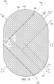
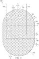
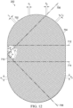
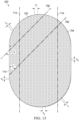
- the foam member may include an edge, and the first direction may be parallel to the edge. According to example embodiments, and the first direction may be rotated an angle ⁇ in a range of about 0° to about 90° with respect to the edge. In some examples, ⁇ may be about 45°. In some embodiments, the foam member may include an edge, and the second direction may be rotated an angle (p in a range of about 0° to about 180° with respect to the edge. In example embodiments, the second direction may be orthogonal to the edge. In illustrative embodiments, ⁇ may be about 135°. According to illustrative examples, the first pattern of rows may be staggered a third angle ⁇ , wherein ⁇ may be about 45°. According to some examples, the second pattern of rows may be staggered a fourth angle y, wherein y may be about 135°.
- some example embodiments may include a dressing for treating a tissue site with negative pressure.
- the dressing may include a cover having an adhesive and a felted foam member having a felted surface.
- the felted foam member may have a first plurality of perforations formed through the felted foam member.
- the dressing may also include a perforated gel layer having a treatment aperture.
- the cover, the felted foam member, and the perforated gel layer may be assembled in a stacked relationship with the cover and the perforated gel enclosing the felted foam member.
- the felted surface may be at least partially exposed through the treatment aperture. At least some of the adhesive may be exposed through the perforated gel layer around the treatment aperture.
- the felted foam member may include an open-cell foam.
- the felted foam member may include a reticulated polyurethane foam.
- the felted foam member may have a density in a range of about 2.6 lb/ft 3 to about 16 lb/ft 3 .
- the felted foam member may have an average pore size in a range of about 50 micrometers to about 300 micrometers.
- the felted foam member may have a free volume in a range of about 9% to about 45%.
- the felted foam member may have an average porosity in a range of about 80 pores per inch to about 500 pores per inch.
- the felted foam member may have a 25% compression load deflection in a range of about 0.7 pounds per square inch to about 3.5 pounds per square inch. In some example embodiments, the felted foam member may have a 65% compression load deflection of about 0.86 pounds per square inch to about 4.3 pounds per square inch.
- the dressing may also include an open-cell foam member disposed between the felted foam member and the cover.
- the open-cell foam member may include a reticulated open-cell polyurethane foam having a density in a range of about 1.3 lb/ft 3 to about 1.6 lb/ft 3 , an average pore size in a range of about 400 micrometers to about 600 micrometers, a free volume of about 90%, an average porosity in a range of about 40 pores per inch to about 50 pores per inch, a 25% compression load deflection of about 0.32 pounds per square inch, and a 65% compression load deflection of about 0.43 pounds per square inch.
- each of the first plurality of perforations may be a slot formed through the felted foam member.
- the slot may have a length in a range of about 1 millimeter to about 5 millimeters.
- the slots may be arranged in a uniform pattern of parallel rows and columns. In example embodiments, the slots may be spaced about 3 millimeters on center. In illustrative examples, the slots in adjacent rows may be offset.
- a system for treating a tissue site with negative pressure is also described herein, wherein some example embodiments include a dressing configured to be placed adjacent to the tissue site.
- the dressing may include a sealing layer with a central aperture and a first plurality of perforations around the central aperture.
- the dressing may also include a felted foam member having a second plurality of perforations extending through the felted foam member. At least a portion of the felted foam member may be exposed through the central aperture.
- a film may be disposed over the felted foam member and the sealing layer. The film may be coupled to the sealing layer around the felted foam member.
- the system may also include a negative-pressure source configured to provide negative pressure to the tissue site through the felted foam member.
- the felted foam member may include an open-cell reticulated polyurethane foam.
- the felted foam member may have a density in a range of about 2.6 lb/ft 3 to about 16 lb/ft 3 , an average pore size in a range of about 50 micrometers to about 300 micrometers, a free volume in a range of about 9% to about 45%, an average porosity in a range of about 80 pore per inch to about 500 pores per inch, a 25% compression load deflection in a range of about 0.7 pounds per square inch to about 3.5 pounds per square inch, and a 65% compression load deflection in a range of about 0.86 pounds per square inch to about 4.3 pounds per square inch.
- the felted foam member may include an open-cell reticulated polyurethane foam.
- the felted foam member may have a density in a range of about 3.4 lb/ft 3 to about 17 lb/ft 3 , an average pore size in a range of about 40 micrometers to about 300 micrometers, an average porosity in a range of about 40 pores per inch to about 50 pores per inch, a 25% compression load deflection in a range of about 0.7 pounds per square inch to about 3.5 pounds per square inch, and a 65% compression load deflection in a range of about 1.2 pounds per square inch to about 6 pounds per square inch.
- the system may also include an open-cell foam member disposed between the felted foam member and the sealing layer.
- the open-cell foam member may include a reticulated open-cell polyurethane foam having an average pore size in a range of about 400 micrometers to about 600 micrometers, an average porosity in a range of about 40 pores per inch to about 50 pores per inch, and a 25% compression load deflection of about 0.35 pounds per square inch.
- the open-cell foam member may have a density in a range of about 1.3 lb/ft 3 to about 1.6 lb/ft 3 , a free volume of about 90%, and a 65% compression load deflection of about 0.43 pounds per square inch.
- the open-cell foam member may have a density in a range of about 1.7 lb/ft 3 to about 2.1 lb/ft 3 and a 65% compression load deflection of about 0.6 pounds per square inch.
- each of the second plurality of perforations may be a slot formed through the foam member.
- the system may further include a third plurality of perforations formed through the felted foam member.
- each of the third plurality of perforations may be a slot formed through the felted foam member.
- each of the second plurality of perforations may be parallel to a first direction, and each of the third plurality of perforations may be parallel to a second direction.
- the second plurality of perforations may be arranged in a first pattern of rows, and the third plurality of perforations may be arranged in a second pattern of rows.
- the first direction may be orthogonal to the second direction.
- the felted foam member may include an edge, and the first direction may be parallel to the edge.
- the first direction may be rotated an angle ⁇ in a range of about 0° to about 90° with respect to the edge. In some examples, ⁇ may be about 45°.
- the second direction may be rotated an angle ⁇ in a range of about 0° to about 180° with respect to the edge. In illustrative embodiments, ⁇ may be about 135°.
- the first pattern of rows may be staggered a third angle ⁇
- the second pattern of rows may be staggered a fourth angle y.
- ⁇ may be about 45°.
- y may be about 135°.
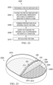
- a method for manufacturing a dressing including the steps of placing a pre-polymer mixture and water into a mold to generate a reaction that produces a foam and an integral film on at least one surface of the foam, forming a first plurality of perforations in the integral film of the foam, providing a gel layer having a treatment aperture and a second plurality of perforations disposed around the treatment aperture, providing a cover with adhesive disposed on a side of the cover, and assembling the cover, the foam, and the gel layer in a stacked relationship.
- the cover and the gel layer may enclose the foam, the foam may be at least partially exposed through the treatment aperture, and at least some of the adhesive may be exposed through some of the second plurality of perforations.
- the mold may be an open tray, and the method may further include the step of skiving a top surface of the foam formed in the open tray.
- the mold may include a bottom side having a first surface facing an interior of the mold.
- the first surface may be smooth.
- each of the first plurality of perforations may include a slit formed through the integral foam.
- each of the slits may have a length in a range of about 2 millimeters to about 5 millimeters.
- the slits may be distributed across the integral film in a uniform pattern of parallel rows and columns.
- the slits may be spaced about 3 millimeters on center. In example embodiments, each of the rows may be spaced about 3 millimeters on center. In illustrative embodiments, the slits in adjacent rows may be offset. According to example embodiments, the step of forming the first plurality of perforations may include using a blade to make the slits in the integral film.
- the mold may include a bottom surface and a plurality of projections on the bottom surface.
- the first plurality of perforations may be formed by the plurality of projections.
- each projection may have a length in a range of about 1 millimeter to about 5 millimeters.
- each projection may have a width in a range of about 0.4 millimeters to about 1 millimeter.
- the projections may be distributed across the bottom surface in a uniform pattern of rows and columns.
- the projections may be spaced about 3 millimeters on center.
- each of the rows may be spaced about 3 millimeters on center.
- the projections in adjacent rows may be offset.
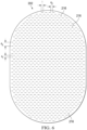
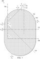
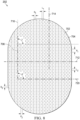
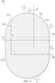
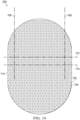
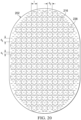
- the mold may include a plurality of walls, a base portion, and a first plurality of projections formed on the base portion.
- the first plurality of projections may be arranged in a first pattern of rows. Each of the first plurality of projections may be parallel to a first direction.
- the projections within each row of the first pattern of rows may be evenly distributed.
- the rows of the first pattern of rows may be evenly distributed.
- the first pattern of rows may have a first pitch P 1 in a range of about 4 millimeters to about 6 millimeters.
- each projection in each row of the first pattern of rows may be spaced a first distance D 1 from an adjacent projection.
- D 1 may be in a range of about 3 millimeters to 5 millimeters.
- the first direction may be rotated a first angle ⁇ in a range of about 0° to about 90° with respect to an edge of the base portion. In some examples, ⁇ may be about 45°.
- each projection of the first plurality of projections may have a centroid incident to a reference line parallel to a third direction.
- the third direction may be orthogonal to the first direction.
- the first pattern of rows may be staggered a third angle ⁇ .
- each projection of the first plurality of projections may have a linear slot profile. In illustrative examples, each projection of the first plurality of projections may have a curved slot profile. According to some examples, each projection of the first plurality of projections may have a chevron slot shape.
- Some example embodiments may include a second plurality of projections formed on the base portion.
- the second plurality of projections may be arranged in a second pattern of rows.
- Each of the second plurality of projections may be parallel to a second direction.
- the rows of the second pattern may be evenly distributed.
- the second pattern of rows may have a second pitch P 2 in a range of about 3 millimeters to about 6 millimeters.
- each projection in each row of the second pattern of rows may be spaced a second distance D 2 from an adjacent projection.
- D 2 may be in a range of about 3 millimeters to about 5 millimeters.
- the first direction may be orthogonal to the second direction.
- the second direction may be orthogonal to an edge of the base portion.
- the first direction may be parallel to the second direction.
- the second direction may be rotated a second angle (p in a second range of about 0° to about 180° with respect to an edge of the base portion. For example, (p may be about 135°.
- each projection of the second plurality of projections may have a centroid incident to a reference line in a fourth direction.
- the fourth direction may be parallel to the first direction.
- each projection of the first plurality of projections may have a first centroid
- each projection of the second plurality of projections may have a second centroid
- each of the first centroids may be aligned with one of the second centroids along a fourth direction.
- each of the first centroids may be coincident with one of the second centroids.
- the second pattern of rows may be staggered a fourth angle y.
- y may be about 135°.
- each projection of the second plurality of projections may have a linear slot profile.
- each projection of the second plurality of projections may have a curved slot profile.
- each projection of the second plurality of projections may have a chevron slot profile.
- the base portion may include a margin without projections.
- the margin may be between about 30% to about 80% of an area of the base portion.
- the plurality of walls may form a stadium shape.
- the plurality of walls may have a profile formed of a rectangle with semicircles at opposite ends of the rectangle.
- Figure 1 is a block diagram of an example embodiment of a therapy system 100 including an example dressing 104 that can provide negative-pressure therapy and instillation treatment in accordance with this specification.
- tissue site in this context broadly refers to a wound, defect, or other treatment target located on or within tissue, including, but not limited to, bone tissue, adipose tissue, muscle tissue, neural tissue, dermal tissue, vascular tissue, connective tissue, cartilage, tendons, or ligaments.
- a wound may include chronic, acute, traumatic, subacute, and dehisced wounds, partial-thickness burns, ulcers (such as diabetic, pressure, or venous insufficiency ulcers), flaps, and grafts, for example.
- tissue site may also refer to areas of any tissue that are not necessarily wounded or defective, but are instead areas in which it may be desirable to add or promote the growth of additional tissue. For example, negative pressure may be applied to a tissue site to grow additional tissue that may be harvested and transplanted.
- the therapy system 100 may include a source or supply of negative pressure, such as a negative-pressure source 102, and one or more distribution components.
- a distribution component is preferably detachable and may be disposable, reusable, or recyclable.
- a dressing, such as a dressing 104, and a fluid container, such as a container 106, are examples of distribution components that may be associated with some examples of the therapy system 100.
- the dressing 104 may include a tissue interface 108, a cover 110, or both in some embodiments.
- a fluid conductor is another illustrative example of a distribution component.
- a tube is an elongated, cylindrical structure with some flexibility, but the geometry and rigidity may vary.
- some fluid conductors may be molded into or otherwise integrally combined with other components.
- Distribution components may also include interfaces or fluid ports to facilitate coupling and de-coupling other components.
- a dressing interface may facilitate coupling a fluid conductor to the dressing 104.
- such a dressing interface may be a SENSAT.R.A.C. TM Pad available from Kinetic Concepts, Inc. of San Antonio, Texas.
- the therapy system 100 may also include a regulator or controller, such as a controller 112. Additionally, the therapy system 100 may include sensors to measure operating parameters and provide feedback signals to the controller 112 indicative of the operating parameters. As illustrated in Figure 1 , for example, the therapy system 100 may include a first sensor 114 and a second sensor 116 coupled to the controller 112.
- the therapy system 100 may also include a source of instillation solution.
- a solution source 118 may be fluidly coupled to the dressing 104, as illustrated in the example embodiment of Figure 1 .
- the solution source 118 may be fluidly coupled to a positive-pressure source such as a positive-pressure source 120, a negative-pressure source such as the negative-pressure source 102, or both in some embodiments.
- a regulator such as an instillation regulator 122, may also be fluidly coupled to the solution source 118 and the dressing 104 to ensure proper dosage of instillation solution (e.g. saline) to a tissue site.
- the instillation regulator 122 may include a piston that can be pneumatically actuated by the negative-pressure source 102 to draw instillation solution from the solution source during a negative-pressure interval and to instill the solution to a dressing during a venting interval. Additionally or alternatively, the controller 112 may be coupled to the negative-pressure source 102, the positive-pressure source 120, or both, to control dosage of instillation solution to a tissue site. In some embodiments, the instillation regulator 122 may also be fluidly coupled to the negative-pressure source 102 through the dressing 104, as illustrated in the example of Figure 1 .
- Some components of the therapy system 100 may be housed within or used in conjunction with other components, such as sensors, processing units, alarm indicators, memory, databases, software, display devices, or user interfaces that further facilitate therapy.
- the negative-pressure source 102 may be combined with the controller 112, the solution source 118, and other components into a therapy unit.
- components of the therapy system 100 may be coupled directly or indirectly.
- the negative-pressure source 102 may be directly coupled to the container 106 and may be indirectly coupled to the dressing 104 through the container 106. Coupling may include fluid, mechanical, thermal, electrical, or chemical coupling (such as a chemical bond), or some combination of coupling in some contexts.
- the negative-pressure source 102 may be electrically coupled to the controller 112 and may be fluidly coupled to one or more distribution components to provide a fluid path to a tissue site.
- components may also be coupled by virtue of physical proximity, being integral to a single structure, or being formed from the same piece of material.
- a negative-pressure supply such as the negative-pressure source 102, may be a reservoir of air at a negative pressure or may be a manual or electrically-powered device, such as a vacuum pump, a suction pump, a wall suction port available at many healthcare facilities, or a micro-pump, for example.
- Negative pressure generally refers to a pressure less than a local ambient pressure, such as the ambient pressure in a local environment external to a sealed therapeutic environment. In many cases, the local ambient pressure may also be the atmospheric pressure at which a tissue site is located. Alternatively, the pressure may be less than a hydrostatic pressure associated with tissue at the tissue site. Unless otherwise indicated, values of pressure stated herein are gauge pressures.
- references to increases in negative pressure typically refer to a decrease in absolute pressure, while decreases in negative pressure typically refer to an increase in absolute pressure. While the amount and nature of negative pressure provided by the negative-pressure source 102 may vary according to therapeutic requirements, the pressure is generally a low vacuum, also commonly referred to as a rough vacuum, between -5 mm Hg (-667 Pa) and -500 mm Hg (-66.7 kPa). Common therapeutic ranges are between - 50 mm Hg (-6.7 kPa) and -300 mm Hg (-39.9 kPa).
- the container 106 is representative of a container, canister, pouch, or other storage component, which can be used to manage exudates and other fluids withdrawn from a tissue site.
- a rigid container may be preferred or required for collecting, storing, and disposing of fluids.
- fluids may be properly disposed of without rigid container storage, and a re-usable container could reduce waste and costs associated with negative-pressure therapy.
- a controller such as the controller 112 may be a microprocessor or computer programmed to operate one or more components of the therapy system 100, such as the negative-pressure source 102.
- the controller 112 may be a microcontroller, which generally includes an integrated circuit containing a processor core and a memory programmed to directly or indirectly control one or more operating parameters of the therapy system 100. Operating parameters may include the power applied to the negative-pressure source 102, the pressure generated by the negative-pressure source 102, or the pressure distributed to the tissue interface 108, for example.
- the controller 112 is also preferably configured to receive one or more input signals, such as a feedback signal, and programmed to modify one or more operating parameters based on the input signals.
- Sensors such as the first sensor 114 and the second sensor 116, are generally known in the art as any apparatus operable to detect or measure a physical phenomenon or property, and generally provide a signal indicative of the phenomenon or property that is detected or measured.
- the first sensor 114 and the second sensor 116 may be configured to measure one or more operating parameters of the therapy system 100.
- the first sensor 114 may be a transducer configured to measure pressure in a pneumatic pathway and convert the measurement to a signal indicative of the pressure measured.
- the first sensor 114 may be a piezo-resistive strain gauge.
- the second sensor 116 may optionally measure operating parameters of the negative-pressure source 102, such as a voltage or current, in some embodiments.
- the signals from the first sensor 114 and the second sensor 116 are suitable as an input signal to the controller 112, but some signal conditioning may be appropriate in some embodiments.
- the signal may need to be filtered or amplified before it can be processed by the controller 112.
- the signal is an electrical signal, but may be represented in other forms, such as an optical signal.
- the tissue interface 108 can be generally adapted to partially or fully contact a tissue site.
- the tissue interface 108 may take many forms, and may have many sizes, shapes, or thicknesses, depending on a variety of factors, such as the type of treatment being implemented or the nature and size of a tissue site.
- the size and shape of the tissue interface 108 may be adapted to the contours of deep and irregular shaped tissue sites. Any or all of the surfaces of the tissue interface 108 may have an uneven, coarse, or jagged profile.
- the tissue interface 108 may include or may be a manifold as further described herein.
- a manifold in this context may include a means for communicating fluid relative to a tissue site under pressure, such as a means for collecting fluid from or distributing fluid to the tissue site.
- a manifold may be adapted to receive negative pressure from a source and distribute negative pressure through multiple apertures across the tissue interface 108, which may have the effect of collecting fluid from a tissue site and drawing the fluid toward the source.
- the fluid path may be reversed or a secondary fluid path may be provided to facilitate delivering fluid, such as fluid from a source of instillation solution, across a tissue site.
- a manifold may include a plurality of pathways, which can be interconnected to improve distribution or collection of fluids.
- a manifold may include a porous material having interconnected fluid pathways.
- suitable porous material that can be adapted to form interconnected fluid pathways may include cellular foam, including open-cell foam such as reticulated foam; porous tissue collections; and other porous material such as gauze or felted mat that generally include pores, edges, and/or walls.
- Liquids, gels, and other foams may also include or be cured to include apertures and fluid pathways.
- a manifold may additionally or alternatively include projections that form interconnected fluid pathways.
- a manifold may be molded to provide surface projections that define interconnected fluid pathways.
- the tissue interface 108 may include reticulated foam having pore sizes and free volume that may vary according to needs of a prescribed therapy.
- reticulated foam having a free volume of at least 90% may be suitable for many therapy applications, and foam having an average pore size in a range of 400-600 microns (40-50 pores per inch) may be particularly suitable for some types of therapy.
- the tensile strength of the tissue interface 108 may also vary according to needs of a prescribed therapy. For example, the tensile strength of foam may be increased for instillation of topical treatment solutions.
- the 25% compression load deflection of the tissue interface 108 may be at least 0.35 pounds per square inch, and the 65% compression load deflection may be at least 0.43 pounds per square inch.
- the tensile strength of the tissue interface 108 may be at least 10 pounds per square inch.
- the tissue interface 108 may have a tear strength of at least 2.5 pounds per inch.
- the tissue interface may be foam including of polyols such as polyester or polyether, isocyanate such as toluene diisocyanate, and polymerization modifiers such as amines and tin compounds.
- the tissue interface 108 may be reticulated polyurethane foam such as found in GRANUFOAM TM dressing or V.A.C. VERAFLO TM dressing, both available from Kinetic Concepts, Inc. of San Antonio, Texas.
- the thickness of the tissue interface 108 may also vary according to needs of a prescribed therapy. For example, the thickness of the tissue interface may be decreased to reduce tension on peripheral tissue. The thickness of the tissue interface 108 can also affect the conformability of the tissue interface 108. In some embodiments, a thickness in a range of about 5 millimeters to 10 millimeters may be suitable.
- the tissue interface 108 may be either hydrophobic or hydrophilic.
- the tissue interface 108 may also wick fluid away from a tissue site, while continuing to distribute negative pressure to the tissue site.
- the wicking properties of the tissue interface 108 may draw fluid away from a tissue site by capillary flow or other wicking mechanisms.
- An example of a hydrophilic material that may be suitable is a polyvinyl alcohol, open-cell foam such as V.A.C. WHITEFOAM TM dressing available from Kinetic Concepts, Inc. of San Antonio, Texas.
- Other hydrophilic foams may include those made from polyether.
- Other foams that may exhibit hydrophilic characteristics include hydrophobic foams that have been treated or coated to provide hydrophilicity.
- the tissue interface 108 may be constructed from bioresorbable materials. Suitable bioresorbable materials may include, without limitation, a polymeric blend of polylactic acid (PLA) and polyglycolic acid (PGA). The polymeric blend may also include, without limitation, polycarbonates, polyfumarates, and capralactones.
- the tissue interface 108 may further serve as a scaffold for new cell-growth, or a scaffold material may be used in conjunction with the tissue interface 108 to promote cell-growth.
- a scaffold is generally a substance or structure used to enhance or promote the growth of cells or formation of tissue, such as a three-dimensional porous structure that provides a template for cell growth.
- Illustrative examples of scaffold materials include calcium phosphate, collagen, PLA/PGA, coral hydroxy apatites, carbonates, or processed allograft materials.
- the cover 110 may provide a bacterial barrier and protection from physical trauma.
- the cover 110 may also be constructed from a material that can reduce evaporative losses and provide a fluid seal between two components or two environments, such as between a therapeutic environment and a local external environment.
- the cover 110 may include, for example, an elastomeric film or membrane that can provide a seal adequate to maintain a negative pressure at a tissue site for a given negative-pressure source.
- the cover 110 may have a high moisture-vapor transmission rate (MVTR) in some applications.
- the MVTR may be at least 250 grams per square meter per twenty-four hours in some embodiments, measured using an upright cup technique according to ASTM E96/E96M Upright Cup Method at 38°C and 10% relative humidity (RH).
- RH relative humidity
- an MVTR up to 5,000 grams per square meter per twenty-four hours may provide effective breathability and mechanical properties.
- the cover 110 may be a polymer drape, such as a polyurethane film, that is permeable to water vapor but impermeable to liquid.
- a polymer drape such as a polyurethane film
- Such drapes typically have a thickness in the range of 25-50 microns.
- the permeability generally should be low enough that a desired negative pressure may be maintained.
- the cover 110 may include, for example, one or more of the following materials: polyurethane (PU), such as hydrophilic polyurethane; cellulosics; hydrophilic polyamides; polyvinyl alcohol; polyvinyl pyrrolidone; hydrophilic acrylics; silicones, such as hydrophilic silicone elastomers; natural rubbers; polyisoprene; styrene butadiene rubber; chloroprene rubber; polybutadiene; nitrile rubber; butyl rubber; ethylene propylene rubber; ethylene propylene diene monomer; chlorosulfonated polyethylene; polysulfide rubber; ethylene vinyl acetate (EVA); co-polyester; and polyether block polymide copolymers.
- PU polyurethane
- PU polyurethane
- hydrophilic polyurethane such as hydrophilic polyurethane
- cellulosics such as cellulosics; hydrophilic polyamides;
- the cover 110 may include INSPIRE 2301 having an MVTR (upright cup technique) of 2600 g/m 2 /24 hours and a thickness of about 30 microns.
- An attachment device may be used to attach the cover 110 to an attachment surface, such as undamaged epidermis, a gasket, or another cover.
- the attachment device may take many forms.
- an attachment device may be a medically-acceptable, pressure-sensitive adhesive configured to bond the cover 110 to epidermis around a tissue site.
- some or all of the cover 110 may be coated with an adhesive, such as an acrylic adhesive, which may have a coating weight of about 25-65 grams per square meter (g.s.m.). Thicker adhesives, or combinations of adhesives, may be applied in some embodiments to improve the seal and reduce leaks.
- Other example embodiments of an attachment device may include a double-sided tape, paste, hydrocolloid, hydrogel, silicone gel, or organogel.
- the solution source 118 may also be representative of a container, canister, pouch, bag, or other storage component, which can provide a solution for instillation therapy.
- Compositions of solutions may vary according to a prescribed therapy, but examples of solutions that may be suitable for some prescriptions include hypochlorite-based solutions, silver nitrate (0.5%), sulfur-based solutions, biguanides, cationic solutions, and isotonic solutions.
- the tissue interface 108 may be placed within, over, on, or otherwise proximate to a tissue site. If the tissue site is a wound, for example, the tissue interface 108 may partially or completely fill the wound, or it may be placed over the wound.
- the cover 110 may be placed over the tissue interface 108 and sealed to an attachment surface near a tissue site. For example, the cover 110 may be sealed to undamaged epidermis peripheral to a tissue site.
- the dressing 104 can provide a sealed therapeutic environment proximate to a tissue site, substantially isolated from the external environment, and the negative-pressure source 102 can reduce pressure in the sealed therapeutic environment.
- downstream typically implies a position in a fluid path relatively closer to a source of negative pressure or further away from a source of positive pressure.
- upstream implies a position relatively further away from a source of negative pressure or closer to a source of positive pressure.
- Negative pressure applied to the tissue site through the tissue interface 108 in the sealed therapeutic environment can induce macro-strain and micro-strain in the tissue site. Negative pressure can also remove exudate and other fluid from a tissue site, which can be collected in container 106.
- the controller 112 may receive and process data from one or more sensors, such as the first sensor 114. The controller 112 may also control the operation of one or more components of the therapy system 100 to manage the pressure delivered to the tissue interface 108.
- controller 112 may include an input for receiving a desired target pressure and may be programmed for processing data relating to the setting and inputting of the target pressure to be applied to the tissue interface 108.
- the target pressure may be a fixed pressure value set by an operator as the target negative pressure desired for therapy at a tissue site and then provided as input to the controller 112.
- the target pressure may vary from tissue site to tissue site based on the type of tissue forming a tissue site, the type of injury or wound (if any), the medical condition of the patient, and the preference of the attending physician.
- the controller 112 can operate the negative-pressure source 102 in one or more control modes based on the target pressure and may receive feedback from one or more sensors to maintain the target pressure at the tissue interface 108.
- the controller 112 may have a continuous pressure mode, in which the negative-pressure source 102 is operated to provide a constant target negative pressure for the duration of treatment or until manually deactivated. Additionally or alternatively, the controller may have an intermittent pressure mode. In example embodiments, the controller 112 can operate the negative-pressure source 102 to cycle between a target pressure and atmospheric pressure. For example, the target pressure may be set at a value of 135 mmHg for a specified period of time (e.g., 5 min), followed by a specified period of time (e.g., 2 min) of deactivation. The cycle can be repeated by activating the negative-pressure source 102, which can form a square wave pattern between the target pressure and atmospheric pressure.
- the increase in negative-pressure from ambient pressure to the target pressure may not be instantaneous.
- the negative-pressure source 102 and the dressing 104 may have an initial rise time.
- the initial rise time may vary depending on the type of dressing and therapy equipment being used.
- the initial rise time for one therapy system may be in a range of about 20-30 mmHg/second and in a range of about 5-10 mmHg/second for another therapy system. If the therapy system 100 is operating in an intermittent mode, the repeating rise time may be a value substantially equal to the initial rise time.
- the target pressure can vary with time.
- the target pressure may vary in the form of a triangular waveform, varying between a negative pressure of 50 and 135 mmHg with a rise rate of negative pressure set at a rate of 25 mmHg/min. and a descent rate set at 25 mmHg/min.
- the triangular waveform may vary between negative pressure of 25 and 135 mmHg with a rise rate of about 30 mmHg/min. and a descent rate set at about 30 mmHg/min.
- the controller 112 may control or determine a variable target pressure in a dynamic pressure mode, and the variable target pressure may vary between a maximum and minimum pressure value that may be set as an input prescribed by an operator as the range of desired negative pressure.
- the variable target pressure may also be processed and controlled by the controller 112, which can vary the target pressure according to a predetermined waveform, such as a triangular waveform, a sine waveform, or a saw-tooth waveform.
- the waveform may be set by an operator as the predetermined or time-varying negative pressure desired for therapy.
- the controller 112 may receive and process data, such as data related to instillation solution provided to the tissue interface 108.
- data may include the type of instillation solution prescribed by a clinician, the volume of fluid or solution to be instilled to a tissue site ("fill volume"), and the amount of time prescribed for leaving solution at a tissue site ("dwell time") before applying a negative pressure to the tissue site.
- the fill volume may be, for example, between 10 and 500 mL, and the dwell time may be between one second to 30 minutes.
- the controller 112 may also control the operation of one or more components of the therapy system 100 to instill solution. For example, the controller 112 may manage fluid distributed from the solution source 118 to the tissue interface 108.
- fluid may be instilled to a tissue site by applying a negative pressure from the negative-pressure source 102 to reduce the pressure at the tissue site, drawing solution into the tissue interface 108.
- solution may be instilled to a tissue site by applying a positive pressure from the positive-pressure source 120 to move solution from the solution source 118 to the tissue interface 108.
- the solution source 118 may be elevated to a height sufficient to allow gravity to move solution into the tissue interface 108.
- the controller 112 may also control the fluid dynamics of instillation by providing a continuous flow of solution or an intermittent flow of solution. Negative pressure may be applied to provide either continuous flow or intermittent flow of solution.
- the application of negative pressure may be implemented to provide a continuous pressure mode of operation to achieve a continuous flow rate of instillation solution through the tissue interface 108, or it may be implemented to provide a dynamic pressure mode of operation to vary the flow rate of instillation solution through the tissue interface 108.
- the application of negative pressure may be implemented to provide an intermittent mode of operation to allow instillation solution to dwell at the tissue interface 108. In an intermittent mode, a specific fill volume and dwell time may be provided depending, for example, on the type of tissue site being treated and the type of dressing being utilized. After or during instillation of solution, negative-pressure treatment may be applied.
- the controller 112 may be utilized to select a mode of operation and the duration of the negative pressure treatment before commencing another instillation cycle by instilling more solution.
- FIG 2A is an exploded view of an example of the dressing 104 of Figure 1 , illustrating additional details that may be associated with some embodiments in which a tissue interface 108 that may be associated with the dressing 104 includes more than one layer.
- the tissue interface 108 may include a first layer, such as a manifold 202, and a second layer, such as a sealing layer 204.
- the dressing 104 may also include the cover 110.
- the manifold 202 may be formed from a porous foam, including the previously described foams of the GRANUFOAM TM dressing, the reticulated polyurethane foam of the V.A.C. VERAFLO TM dressing, or the polyvinyl alcohol, open-celled V.A.C. WHITEFOAM TM .
- a portion of the manifold 202 may be formed by a felting process. Felting may be performed by any known methods, which may include applying heat and pressure to a porous material or foam material. Some methods may include compressing a foam blank between one or more heated platens or dies (not shown) for a specified period of time and at a specified temperature.
- the direction of compression may be along the thickness of the foam blank.
- the period of time of compression may range from 10 minutes up to 24 hours, though the time period may be more or less depending on the specific type of porous material used.
- the temperature may range between 120°C to 260°C. Generally, the lower the temperature of the platen, the longer a porous material must be held in compression. After the specified time period has elapsed, the pressure and heat will form a felted structure or surface on or through the porous material or a portion of the porous material.
- the felting process may alter certain properties of the original material, including pore shape and/or size, elasticity, density, and density distribution.
- struts that define pores in the foam may be deformed during the felting process, resulting in flattened pore shapes.
- the deformed struts can also decrease the elasticity of the foam.
- the density of the foam is generally increased by felting.
- contact with hot-press platens in the felting process can also result in a density gradient in which the density is greater at the surface and the pores size is smaller at the surface.
- the felted structure may be comparatively smoother than any unfinished or non-felted surface or portion of the porous material. Further, the pores in the felted structure may be smaller than the pores throughout any unfinished or non-felted surface or portion of the porous material.
- a felted foam may be characterized by a firmness factor, which is indicative of the compression of the foam.
- the firmness factor of a felted foam can be specified as the ratio of original thickness to final thickness.
- a compressed or felted foam may have a firmness factor greater than 1.
- the degree of compression may affect the physical properties of the felted foam. For example, felted foam has an increased effective density compared to a foam of the same material that is not felted.
- the felting process can also affect fluid-to-foam interactions. For example, as the density increases, compressibility or collapse may decrease. Therefore, foams which have different compressibility or collapse may have different firmness factors.
- a firmness factor can range from about 2 to about 10, preferably about 3 to about 7.
- foam that is felted to a firmness factor of 3 will show a three-fold density increase and compress to about a third of its original thickness.
- Foam that is felted to a firmness factor of 3 may show a three-fold decrease in pore size, a three-fold decrease in free volume, a three-fold increase in average pores per inch, a three-fold increase in 25% compression load deflection, and a three-fold increase in 65% compression load deflection.
- the manifold 202 may include a tissue-facing surface or a tissue contact surface such as a first surface 206 opposite a second surface 208, and a periphery 210.
- a portion of the manifold 202 may be felted, such as a felted portion 212.
- the felted portion 212 may extend a depth away from the first surface 206 and into the manifold 202.
- the first surface 206 may be a felted surface.
- the remainder of the manifold 202 may be non-felted, such as non-felted portion 214.
- non-felted portion may extend a depth away from the second surface 208 and into the manifold 202. In some embodiments, the non-felted portion 214 may have the characteristics of the pre-felted foam blank used to form the manifold 202.
- a suitable foam blank (e.g., of pre-felted foam) may be a foam such as GRANUFOAM TM , and may have a density in a range of about 1.3 lb/ft 3 to about 1.6 lb/ft 3 , an average pore size in a range of about 400 micrometers to about 600 micrometers, a free volume of about 90%, an average porosity in a range of about 40 pores per inch to about 50 pores per inch, a 25% compression load deflection of about 0.35 psi, and a 65% compression load deflection of about 0.43 psi.
- a portion of the manifold 202 may be felted to provide a denser foam for the manifold 202.
- the felted portion 212 may be felted to a firmness factor in a range of between about 2 and 10.
- the felted portion 212 may have a density in a range of about 2.6 lb/ft 3 to about 14.4 lb/ft 3 , an average pore size in a range of about 40 micrometers to about 300 micrometers, a free volume in a range of about 9% to about 45%, an average porosity in a range of about 80 pores per inch to about 500 pores per inch, a 25% compression load deflection in a range of about 0.7 psi to about 3.5 psi, and a 65% compression load deflection in a range of about 0.86 psi to about 4.3 psi.
- the felted portion 212 may be felted to a firmness factor of about 2.
- the felted portion 212 may have a density in a range of about 2.6 lb/ft 3 to about 3.2 lb/ft 3 , an average pore size in a range of about 200 micrometers to about 300 micrometers, a free volume of about 45%, an average porosity in a range of about 80 pores per inch to about 100 pores per inch, a 25% compression load deflection of about 0.7 psi, and a 65% compression load deflection of about 0.86 psi.
- the felted portion 212 may be felted to a firmness factor of about 3.
- the felted portion 212 may have a density in a range of about 3.9 lb/ft 3 to about 4.8 lb/ft 3 , an average pore size in a range of about 133.33 micrometers to about 200 micrometers, a free volume of about 30%, an average porosity in a range of about 120 pores per inch to about 150 pores per inch, a 25% compression load deflection of about 1.05 psi, and a 65% compression load deflection of about 1.29 psi.
- the felted portion 212 may be felted to a firmness factor of about 4.
- the felted portion 212 may have a density in a range of about 5.2 lb/ft 3 to about 6.4 lb/ft 3 , an average pore size in a range of about 100 micrometers to about 150 micrometers, a free volume of about 23%, an average porosity in a range of about 160 pores per inch to about 200 pores per inch, a 25% compression load deflection of about 1.4 psi, and a 65% compression load deflection of about 1.72 psi.
- the felted portion 212 may be felted to a firmness factor of about 5.
- the felted portion 212 may have a density in a range of about 6.5 lb/ft 3 to about 8 lb/ft 3 , an average pore size in a range of about 80 micrometers to about 120 micrometers, a free volume of about 18%, an average porosity in a range of about 200 pores per inch to about 250 pores per inch, a 25% compression load deflection of about 1.75 psi, and a 65% compression load deflection of about 2.15 psi.
- the felted portion 212 may be felted to a firmness factor of about 6.
- the felted portion 212 may have a density in a range of about 7.8 lb/ft 3 to about 9.6 lb/ft 3 , an average pore size in a range of about 66.67 micrometers to about 100 micrometers, a free volume of about 15%, an average porosity in a range of about 240 pores per inch to about 300 pores per inch, a 25% compression load deflection of about 2.1 psi, and a 65% compression load deflection of about 2.58 psi.
- the felted portion 212 may be felted to a firmness factor of about 7.
- the felted portion 212 may have a density in a range of about 9.1 lb/ft 3 to about 11.2 lb/ft 3 , an average pore size in a range of about 57.14 micrometers to about 85.71 micrometers, a free volume of about 13%, an average porosity in a range of about 280 pores per inch to about 350 pores per inch, a 25% compression load deflection of about 2.45 psi, and a 65% compression load deflection of about 3.01 psi.
- the felted portion 212 may be felted to a firmness factor of about 8.
- the felted portion 212 may have a density in a range of about 10.4 lb/ft 3 to about 12.8 lb/ft 3 , an average pore size in a range of about 50 micrometers to about 75 micrometers, a free volume of about 11%, an average porosity in a range of about 320 pores per inch to about 400 pores per inch, a 25% compression load deflection of about 2.8 psi, and a 65% compression load deflection of about 3.44 psi.
- the felted portion 212 may be felted to a firmness factor of about 9.
- the felted portion 212 may have a density in a range of about 11.7 lb/ft 3 to about 14.4 lb/ft 3 , an average pore size in a range of about 44.44 micrometers to about 66.67 micrometers, a free volume of about 10%, an average porosity in a range of about 360 pores per inch to about 450 pores per inch, a 25% compression load deflection of about 3.15 psi, and a 65% compression load deflection of about 3.87 psi.
- the felted portion 212 may be felted to a firmness factor of about 10.
- the felted portion 212 may have a density in a range of about 13 lb/ft 3 to about 16 lb/ft 3 , an average pore size in a range of about 40 micrometers to about 60 micrometers, a free volume of about 9%, an average porosity in a range of about 400 pores per inch to about 500 pores per inch, a 25% compression load deflection of about 3.5 psi, and a 65% compression load deflection of about 4.3 psi.
- the pre-felted foam blank may be a foam such as foams found in V.A.C. VERAFLOW TM dressings, and may have a density in a range of about 1.7 lb/ft 3 to about 2.1 lb/ft 3 , an average pore size in a range of about 400 micrometers to about 600 micrometers, an average porosity in a range of about 40 pores per inch to about 50 pores per inch, a 25% compression load deflection of about 0.35 psi, and a 65% compression load deflection of about 0.6 psi.
- foams found in V.A.C. VERAFLOW TM dressings may have a density in a range of about 1.7 lb/ft 3 to about 2.1 lb/ft 3 , an average pore size in a range of about 400 micrometers to about 600 micrometers, an average porosity in a range of about 40 pores per inch to about 50 pores per inch, a 25% compression load deflection of about
- a portion of the manifold 202 such as the felted portion 212 may be felted to provide a denser foam for the manifold.
- the felted portion 212 may be felted to a firmness factor in a range of between about 2 and 10.
- the felted portion 212 may have a density in a range of about 3.4 lb/ft 3 to about 21 lb/ft 3 , an average pore size in a range of about 40 micrometers to about 300 micrometers, an average porosity in a range of about 80 pores per inch to about 500 pores per inch, a 25% compression load deflection in a range of about 0.7 psi to about 3.5 psi, and a 65% compression load deflection in a range of about 0.86 psi to about 4.3 psi.
- the felted portion 212 may be felted to a firmness factor of about 2.
- the felted portion 212 may have a density in a range of about 3.4 lb/ft 3 to about 4.2 lb/ft 3 , an average pore size in a range of about 200 micrometers to about 300 micrometers, an average porosity in a range of about 80 pores per inch to about 100 pores per inch, a 25% compression load deflection of about 0.7 psi, and a 65% compression load deflection of about 0.6 psi.
- the felted portion 212 may be felted to a firmness factor of about 3.
- the felted portion 212 may have a density in a range of about 5.1 lb/ft 3 to about 6.3 lb/ft 3 , an average pore size in a range of about 133.33 micrometers to about 200 micrometers, an average porosity in a range of about 120 pores per inch to about 150 pores per inch, a 25% compression load deflection of about 1.05 psi, and a 65% compression load deflection of about 1.8 psi.
- the felted portion 212 may be felted to a firmness factor of about 4.
- the felted portion 212 may have a density in a range of about 6.8 lb/ft 3 to about 8.4 lb/ft 3 , an average pore size in a range of about 100 micrometers to about 150 micrometers, an average porosity in a range of about 160 pores per inch to about 200 pores per inch, a 25% compression load deflection of about 1.4 psi, and a 65% compression load deflection of about 2.4 psi.
- the felted portion 212 may be felted to a firmness factor of about 5.
- the felted portion 212 may have a density in a range of about 8.5 lb/ft 3 to about 10.5 lb/ft 3 , an average pore size in a range of about 80 micrometers to about 120 micrometers, an average porosity in a range of about 200 pores per inch to about 250 pores per inch, a 25% compression load deflection of about 1.75 psi, and a 65% compression load deflection of about 3 psi.
- the felted portion 212 may be felted to a firmness factor of about 6.
- the felted portion 212 may have a density in a range of about 10.2 lb/ft 3 to about 12.6 lb/ft 3 , an average pore size in a range of about 66.67 micrometers to about 100 micrometers, an average porosity in a range of about 240 pores per inch to about 300 pores per inch, a 25% compression load deflection of about 2.1 psi, and a 65% compression load deflection of about 3.6 psi.
- the felted portion 212 may be felted to a firmness factor of about 7.
- the felted portion 212 may have a density in a range of about 11.9 lb/ft 3 to about 14.7 lb/ft 3 , an average pore size in a range of about 57.14 micrometers to about 85.71 micrometers, an average porosity in a range of about 280 pores per inch to about 350 pores per inch, a 25% compression load deflection of about 2.45 psi, and a 65% compression load deflection of about 4.2 psi.
- the felted portion 212 may be felted to a firmness factor of about 8.
- the felted portion 212 may have a density in a range of about 13.6 lb/ft 3 to about 16.8 lb/ft 3 , an average pore size in a range of about 50 micrometers to about 75 micrometers, an average porosity in a range of about 320 pores per inch to about 400 pores per inch, a 25% compression load deflection of about 2.8 psi, and a 65% compression load deflection of about 4.8 psi.
- the felted portion 212 may be felted to a firmness factor of about 9.
- the felted portion 212 may have a density in a range of about 15.3 lb/ft 3 to about 18.9 lb/ft 3 , an average pore size in a range of about 44.44 micrometers to about 66.67 micrometers, an average porosity in a range of about 360 pores per inch to about 450 pores per inch, a 25% compression load deflection of about 3.15 psi, and a 65% compression load deflection of about 5.4 psi.
- the felted portion 212 may be felted to a firmness factor of about 10.
- the felted portion 212 may have a density in a range of about 17 lb/ft 3 to about 21 lb/ft 3 , an average pore size in a range of about 40 micrometers to about 60 micrometers, an average porosity in a range of about 400 pores per inch to about 500 pores per inch, a 25% compression load deflection of about 3.5 psi, and a 65% compression load deflection of about 6 psi.
- Figure 2B is an exploded view of an example of the dressing 104 of Figure 1 , illustrating additional details that may be associated with some embodiments in which a tissue interface 108 that may be associated with the dressing 104 includes more than one layer.
- the manifold 202 may be felted throughout its thickness such that the felted portion 214 extends from the first surface 206 though the manifold 202 to the second surface 208. In some embodiments, both the first surface 206 and the second surface 208 may be felted surfaces. As shown in Figure 2B , in some embodiments, the manifold 202 may not have a non-felted portion 214.
- one or more perforations 216 may be formed through the felted portion 212.
- the perforations 216 may extend from the first surface 206 to non-felted portion 214, providing fluid communication between the first surface 206 and the non-felted portion 214, through the thickness of the felted portion 212.
- the perforations 216 may extend through the entire thickness of the felted portion 214 and the manifold 202, from the first surface 206 to the second surface 208.
- the perforations 216 may provide fluid communication between the first surface 206 and the second surface 208 through the thickness of the felted portion 212 and the manifold 202.
- the perforations 216 may be formed by removing material from the felted portion 212.
- perforations 216 may be formed by cutting through the felted portion 212.
- each of the perforations 216 may be a slot having a length in a range of about 1 millimeter to about 5 millimeters, and a width in a range of about 0.4 millimeters to about 1 millimeter.
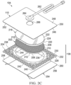
- Figure 2C is an exploded view of an example of the dressing 104 of Figure 1 , illustrating additional details that may be associated with some embodiments in which a tissue interface 108 that may be associated with the dressing 104 includes more than one layer.
- the dressing 104 includes a secondary manifold 218.
- the secondary manifold 218 may comprise a porous foam, such as any foam previously described with respect to the manifold 202.
- the secondary manifold 218 may be formed from a non-felted foam.
- the secondary manifold 218 may include a tissue-facing surface, such as a first surface 220 opposite a second surface 222, and a periphery 224.
- the periphery 224 of the secondary manifold 218 may be substantially coextensive with the periphery 210 of the manifold 202.
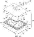
- Figure 2D is an exploded view of an example of the dressing 104 of Figure 1 , illustrating additional details that may be associated with some embodiments in which a tissue interface 108 that may be associated with the dressing 104 includes more than one layer.
- the manifold 202 may not be felted.
- the manifold 202 may include a non-felted portion 214, but not a felted portion 212.
- the manifold 202 may include an integrally formed film layer 226 on the first surface 206.
- the film layer 226 may include polymeric film that is integral to the overall structure of the manifold 202.
- the film layer 226 may include a hydrophobic polymeric film.
- the film layer 226 may be a polyurethane film formed on the first surface 206 of the manifold 202 during manufacture of the manifold 202.
- the film layer 226 may include a polyurethane film that is integral to the polyurethane foam of the manifold 202.
- the film layer 226 may be formed from the same material as the manifold 202 such that the manifold 202 integrally transitions from a foam portion, such as the non-felted portion 214 to the film layer 226.
- the structure of the non-felted portion 214 may transition to the film layer 226.
- the film layer 226 may be attached to the non-felted portion 214 without the use of an adhesive or other coupling means.
- suitable polymeric materials for forming the non-felted portion 214 and the film layer 226 may include silicones, elastomeric polyesters (for example, HYTREL ® elastomers), polyether copolymers (such as PEBAX ® elastomers), and isocyanate-free polyurethanes (for example, amineoplast/carbamate copolymers, polycarbamate/polyamine materials, or polycarbamate/polyaldehyde materials).
- the film layer 226 may have material properties that make it conducive to being applied against a tissue site.
- the film layer 226 may have a thickness of between 20 micrometers and 100 micrometers.
- the hydrophobicity of the film layer 226 may be modified or enhanced with a hydrophobic coating of other materials, such as silicones and fluorocarbons, either as coated from a liquid or plasma coated.
- the perforations 216 may be formed through the thickness of the film layer 226 to provide the porous space of the non-felted portion 214 with fluid communication through the film layer 226.
- the perforations 216 may provide fluid communication between the porous spaces of the non-felted portion 214 with an environment opposite the film layer 226 from the non-felted portion 214.
- the film layer 226 may serve as a tissue in-growth barrier, substantially preventing granulation tissue from growing into the manifold 202.
- the dressing 104 may also include a sealing layer 204 formed from a soft, pliable material suitable for providing a fluid seal with a tissue site, such as a suitable gel material.
- the sealing layer 204 may include a silicone gel, a soft silicone, a hydrocolloid, a hydrogel, a polyurethane gel, a polyolefin gel, a hydrogenated styrenic copolymer gel, a foamed gel, a soft closed cell foam (such as polyurethanes and polyolefins coated with an adhesive), polyurethane, polyolefin, or hydrogenated styrenic copolymers.
- the sealing layer 204 may include a tissue-facing surface, such as a first surface 228 opposite a second surface 230, and a periphery 232.
- the first surface 228 and the second surface 230 may be substantially flat surfaces.
- the sealing layer 204 may have a thickness between the first surface 228 and the second surface 230 in a range of about 200 micrometers to about 1,000 micrometers.
- some embodiments of the sealing layer 204 may have an outer region 234 between the periphery 232 and a treatment aperture 236 formed through the sealing layer 204.
- a plurality of apertures 238 may be formed through the sealing layer 204 in the periphery 232 surrounding the treatment aperture 236.
- the treatment aperture 236 may be complementary or correspond to a surface area of the manifold 202 bound by the periphery 210.
- the treatment aperture may form a frame, window, or other opening around a surface of the manifold 202, such as a region of the first surface 206 near the periphery 210.
- the sealing layer 204 may also include corners 240 and edges 242.
- the corners 240 and edges 242 may be a part of the periphery 232.
- the sealing layer 204 may also include an interior border 244 around the treatment aperture 236, which may be substantially free of the apertures 238.
- the treatment aperture 236 may be symmetrical and centrally disposed in the sealing layer 204, forming an open central window.
- the apertures 238 may be formed by cutting, perforating, or by application of local RF or ultrasonic energy, for example, or by other suitable techniques for forming an opening or perforation in the sealing layer 204.
- the apertures 238 may have a uniform distribution pattern, or may be randomly distributed on the sealing layer 204.
- the apertures 238 in the sealing layer 204 may have many shapes, including circles, squares, stars, ovals, polygons, slits, complex curves, rectilinear shapes, triangles, for example, or may have some combination of such shapes.
- each of the apertures 238 may have uniform or similar geometric properties.
- each of the apertures 238 may be circular apertures, having substantially the same diameter.
- each of the apertures 238 may have a diameter of about 1 millimeter to about 50 millimeters. In other embodiments, the diameter of each of the apertures 238 may be about 1 millimeter to about 20 millimeters.
- geometric properties of the apertures 238 may vary.
- the diameter of the apertures 238 may vary depending on the position of the apertures 238 in the sealing layer 204.
- the apertures 238 disposed in the outer region 234 may have a diameter between about 5 millimeters and about 10 millimeters. A range of about 7 millimeters to about 9 millimeters may be suitable for some examples.
- the apertures 238 disposed near the corners 240 may have a diameter between about 7 millimeters and about 8 millimeters.
- At least one of the apertures 238 in the outer region 234 of the sealing layer 204 may be positioned at the edges 242 of the outer region 234, and may have an interior cut open or exposed at the edges 242 that is in fluid communication in a lateral direction with the edges 242.
- the lateral direction may refer to a direction toward the edges 242 and in the same plane as the sealing layer 204.
- the apertures 238 in the outer region 234 may be positioned proximate to or at the edges 242 and in fluid communication in a lateral direction with the edges 242.
- the apertures 238 positioned proximate to or at the edges 242 may be spaced substantially equidistant around the outer region 234 as shown in Figures 2A-2D .
- the spacing of the apertures 238 proximate to or at the edges 242 may be irregular.
- the cover 110 may include a tissue-facing surface, such as a first surface 246 opposite a second surface 248, and a periphery 250.
- the cover 110 may include an attachment device, such as an adhesive 252 disposed on the first surface 246 of the cover 110.
- the adhesive 252 may be, for example, a medically-acceptable, pressure-sensitive adhesive that extends about a periphery, a portion, or an entire surface of the cover 110.
- the adhesive 252 may be an acrylic adhesive having a coating weight between 25-65 grams per square meter (g.s.m.).
- Thicker adhesives, or combinations of adhesives may be applied in some embodiments to improve the seal and reduce leaks.
- a layer of the adhesive 252 may be continuous or discontinuous. Discontinuities in the adhesive 252 may be provided by apertures or holes (not shown) in the adhesive 252.
- the apertures or holes in the adhesive 252 may be formed after application of the adhesive 252 or by coating the adhesive 252 in patterns on a carrier layer, such as, for example, a side of the cover 110. Apertures or holes in the adhesive 252 may also be sized to enhance the MVTR of the dressing 104 in some example embodiments.
- the periphery 250 of the cover 110 may be substantially coextensive with the periphery 232 of the sealing layer 204.
- the dressing 104 may include a release liner 254 to protect the adhesive 252 prior to application of the dressing 104.
- the release liner 254 may also provide stiffness to assist with, for example, the deployment of the dressing 104.
- the release liner 254 may be, for example, a casting paper, a film, or polyethylene.
- the release liner 254 may be a polyester material such as polyethylene terephthalate (PET), or similar polar semi-crystalline polymer.
- PET polyethylene terephthalate
- the use of a polar semi-crystalline polymer for the release liner 254 may substantially preclude wrinkling or other deformation of the dressing 104.
- the polar semi-crystalline polymer may be highly orientated and resistant to softening, swelling, or other deformation that may occur when brought into contact with components of the dressing 104, or when subj ected to temperature or environmental variations, or sterilization.
- the release liner 254 may include a first surface 256 opposite a second surface 258, and a periphery 260.
- a release agent may be disposed on a side of the release liner 254 that is configured to contact the sealing layer 204, manifold 202, and/or the cover 110.
- the release agent may be disposed on the second surface 258 of the release liner 254, and be configured to contact the first surface 228 of the sealing layer 204, the first surface 206 of the manifold 202, and/or the adhesive 252 disposed on the first surface 246 of the cover.
- the release agent may be a silicone coating and may have a release factor suitable to facilitate removal of the release liner 254 by hand and without damaging or deforming the dressing 104.
- the release agent may be a fluorocarbon or a fluorosilicone, for example.
- the release liner 254 may be uncoated or otherwise used without a release agent.
- Figures 2A-2D also illustrate examples of a fluid conductor 262 and a dressing interface 264.
- some examples of the fluid conductor 262 may be a flexible tube, which can be fluidly coupled to the dressing interface 264 on one end of the fluid conductor 262.
- the dressing interface 264 may be an elbow connector which can be placed over an aperture 266 formed through the cover 110 to provide a fluid path between the fluid conductor 262 and the manifold 202.
- One or more of the components of the dressing 104 may additionally be treated with an antimicrobial agent in some embodiments.
- the manifold 202 and/or the secondary manifold 218 may be coated with an antimicrobial agent.
- the manifold 202 and/or the secondary manifold 218 may include antimicrobial elements, such as fibers coated with an antimicrobial agent.
- some embodiments of the manifold 202 and/or the secondary manifold 218 may be a polymer coated or mixed with an antimicrobial agent.
- the fluid conductor 262 may additionally or alternatively be treated with one or more antimicrobial agents.
- Suitable antimicrobial agents may include, for example, metallic silver, PHMB, iodine or its complexes and mixes such as povidone iodine, copper metal compounds, chlorhexidine, or some combination of these materials.
- one or more of the components may be coated with a mixture that may include citric acid and collagen, which can reduce bio-films and infections.
- the primary manifold 202 and/or the secondary manifold 218 may be a foam coated with such a mixture.
- the dressing 104 may be assembled in a stacked relationship with the cover 110 and the sealing layer 204 enclosing the manifold 202.
- the first surface 206 of the manifold 202 may be disposed adjacent to a portion of the second surface 230 of the sealing layer 204.
- a portion of the first surface 206 near the periphery 210 of the manifold 202 may be disposed adjacent to a portion of the second surface 230 near the interior border 244.
- a portion of the first surface 206 may be adhered to a portion of the second surface 230.
- At least a portion of the first surface 246 of the cover 110 may be disposed adjacent to at least a portion of the second surface 208 of the manifold 202 and a portion of the second surface 230 of the sealing layer 204.
- at least a portion of the first surface 246 of the cover 110 near the aperture 266 may be adhered to at least a portion of the second surface 208 of the manifold 202 with the adhesive 252
- at least a portion of the first surface 246 of the cover 110 near the periphery 250 may be adhered to at least a portion of the second surface 230 of the sealing layer 204 at the outer region 234 with the adhesive 252.
- the periphery 250 of the cover 110 may be substantially coextensive with the periphery 232 of the sealing layer 204, and the periphery 210 of the manifold 202 may be substantially contained within the periphery 232 and the periphery 250.
- the dressing 104 may be assembled in a stacked relationship with the cover 110 and the sealing layer 204 enclosing the manifold 202 and the secondary manifold 218.
- the manifold 202 and the secondary manifold 218 may be assembled in a stacked relationship such that at least a portion of the first surface 220 of the secondary manifold 218 may be disposed adjacent to at least a portion of the second surface 208 of the manifold 202.
- at least a portion of the first surface 206 of the manifold 202 may be disposed adjacent to a portion of the second surface 230 of the sealing layer 204.
- a portion of the first surface 206 near the periphery 210 of the manifold 202 may be disposed adjacent to a portion of the second surface 230 near the interior border 244.
- a portion of the first surface 206 may be adhered to a portion of the second surface 230.
- at least a portion of the first surface 246 of the cover 110 may be disposed adjacent to at least a portion of the second surface 222 of the secondary manifold 218 and a portion of the second surface 230 of the sealing layer 204.
- the first surface 246 of the cover 110 near the aperture 266 may be adhered to at least a portion of the second surface 222 of the secondary manifold 218 with the adhesive 252, and at least a portion of the first surface 246 of the cover 110 near the periphery 250 may be adhered to at least a portion of the second surface 230 of the sealing layer 204 at the outer region 234 with the adhesive 252.
- the periphery 224 of the secondary manifold 218 may be substantially coextensive with the periphery 210 of the manifold 202.
- the periphery 250 of the cover 110 may be substantially coextensive with the periphery 232 of the sealing layer 204, and the periphery 224 of the secondary manifold 218 and the periphery 210 of the manifold 202 may be substantially contained within the periphery 232 and the periphery 250.
- Figure 2E is an isometric view of an assembled example of the dressing 104 of Figure 2C .
- the cover 110 may be substantially clear or optically transparent, allowing for visualization of the secondary manifold 218, the manifold 202, and the sealing layer 204 through the cover 110.
- Figure 3 is a top view of the dressing 104 in the example of Figure 2C , as assembled, illustrating additional details that may be associated with some embodiments.
- the cover 110 and the sealing layer 204 may have substantially the same perimeter shape and dimensions, so that the cover 110 and the sealing layer 204 are coextensive in some examples.
- the cover 110 may be substantially transparent, allowing visibility of the apertures 238 in some embodiments.
- the secondary manifold 218 may be centrally disposed over the manifold 202 (not visible in Figure 3 ), such as over the treatment aperture 236 (not visible in Figure 3 ).
- the cover 110 may be disposed over the secondary manifold 218 and manifold 202 and coupled to the sealing layer 204 around the secondary manifold 218 and manifold 202 so that at least some of the adhesive 252 can be disposed adjacent to the apertures 238.
- Figure 4 is a bottom view of the dressing 104 in the example of Figure 2C , as assembled, illustrating additional details that may be associated with some embodiments. As illustrated in the example of Figure 4 , a substantial number of the perforations 216 may be aligned or otherwise exposed through the treatment aperture 236. In some embodiments, the manifold 202 and the secondary manifold 218 may be substantially aligned with the treatment aperture 236, or may extend across the treatment aperture 236.
- the secondary manifold 218 may have a periphery 224
- the manifold 202 may have a periphery 210.
- the periphery 224 and the periphery 210 may have substantially the same shape so that adjacent faces of the secondary manifold 218 and the manifold 202 are geometrically similar.
- the periphery 224 and the periphery 210 may also be congruent in some examples, so that adjacent faces of the secondary manifold 218 and the manifold 202 are substantially coextensive and have substantially the same surface area.
- the periphery 224 defines a larger face of the secondary manifold 218 than the face of the manifold 202 defined by the periphery 210, and the larger face of the secondary manifold 218 extends past the smaller face of the periphery 210.
- the faces defined by the periphery 210, the periphery 224, or both may also be geometrically similar to the treatment aperture 236 in some embodiments, as illustrated in the example of Figure 4 , or may be larger than the treatment aperture 236.
- the sealing layer 204 may have an overlay margin 402 around the treatment aperture 236, which may have an additional adhesive disposed therein.
- the treatment aperture 236 may be an ellipse or a stadium in some embodiments.
- the treatment aperture 236 may have an area that is equal to about 20% to about 80% of the area of the sealing layer 204 in some examples.
- the treatment aperture 236 may also have an area that is equal to about 20% to about 80% of the area of a face of defined by the periphery 210 of the manifold 202.
- a width of about 90 millimeters to about 110 millimeters and a length of about 150 millimeters to about 160 millimeters may be suitable for some embodiments of the treatment aperture 236.
- the width of the treatment aperture 236 may be about 100 millimeters, and the length may be about 155 millimeters.
- a suitable width for the overlay margin 402 may be about 2 millimeters to about 3 millimeters.
- the overlay margin 402 may be coextensive with an area defined between the treatment aperture 236 and the periphery 210, and the adhesive may secure manifold 202 to the sealing layer 204.
- Figure 5 is an exploded view of another example of the dressing 104 of Figure 1 , illustrating additional details that may be associated with some embodiments. As illustrated in Figure 5 , some examples of the sealing layer 204 may not have the treatment aperture 236, and the apertures 238 may be distributed in a uniform pattern across the sealing layer 204.
- Figure 6 is a bottom view of an example of a manifold 202 that may be associated with any example embodiments of the dressing 104 or the tissue interface 108, illustrating an example pattern of perforations that may be associated with some embodiments.
- the perforations 216 formed through the felted portion 212 or the integral film layer 226 may each consist essentially of one or more slits or slots having a length l . A length of about 3 millimeters may be particularly suitable for some embodiments.
- Figure 6 additionally illustrates an example of a uniform distribution pattern of the perforations 216.
- the perforations 216 are substantially coextensive with the manifold 202, and are distributed across the manifold 202 in a grid of parallel rows and columns, in which the slits or slots are also mutually parallel to each other.
- the rows may be spaced a distance d 1 .
- a distance of about 3 millimeters on center may be suitable for some embodiments.
- the perforations 216 within each of the rows may be spaced a distance d 2 , which may be about 3 millimeters on center in some examples.
- the perforations 216 in adjacent rows may be aligned or offset in some embodiments.
- adjacent rows may be offset, as illustrated in Figure 6 , so that the perforations 216 are aligned in alternating rows and separated by a distance d 3 , which may be about 6 millimeters in some embodiments.
- the spacing of the perforations 216 may vary in some embodiments to increase the density of the perforations 216 according to therapeutic requirements.
- Figures 7 through 14 are bottom views of example manifolds 202 that may be associated with any example embodiments of the dressing 104 or tissue interface 108, illustrating example patterns of perforations 216 that may be associated with some example embodiments.
- the perforations 216 formed through the felted portion 212 or the integral film layer 226 may comprise a first plurality of perforations 702 and a second plurality of perforations 704.
- Each of the first plurality of perforations 702 and the second plurality of perforations 704 may be linear or curved perforations, such as slots or slits.
- each of the first plurality of perforations 702 may have a length L 1 and each of the second plurality of perforations 704 may have a length L 2 .
- each of the first plurality of perforations may have a length L 1 measured from an end of the curved slot or slit to the other end of the curved slot or slit
- each of the second plurality of perforations may have a length L 2 measured from an end of the curved slot or slit to the other end of the curved slot or slit.
- the length L 1 may be equal to the length L 2 .
- the first plurality of perforations 702 and the second plurality of perforations 704 may be distributed across the second layer in one or more rows in one direction or in different directions.
- each of the first plurality of perforations 702 may have a first long axis.
- the first long axis may be parallel to a first reference line 706 running in a first direction.
- each of the second plurality of perforations 704 may have a second long axis.
- the second long axis may be parallel to a second reference line 708 running in a second direction.
- one or both of the first reference line 706 and the second reference line 708 may be defined relative to an edge 710 or line of symmetry of the first surface 206.
- first reference line 706 and the second reference line 708 may be parallel or coincident with an edge 710 or line of symmetry of the first surface 206.
- one or both of the first reference line 706 and the second reference line 708 may be rotated an angle relative to an edge 710 of the first surface 206.
- an angle ⁇ may define the angle between the first reference line 706 and the second reference line 708.
- centroid of each of the first plurality of perforations 702 within a row may intersect a third reference line 712 running in a third direction.
- centroid of each of the second plurality of perforations 704 within a row may intersect a fourth reference line 714 running in a fourth direction.
- a centroid refers to the center of mass of a geometric object. In the case of a substantially two dimensional object such as a linear slit, the centroid of the linear slit will be the midpoint.
- the pattern of perforations 216 may also be characterized by a pitch, which indicates the spacing between corresponding points on perforations 216 within a pattern.
- pitch may indicate the spacing between the centroids of perforations 216 within the pattern.
- Some patterns may be characterized by a single pitch value, while others may be characterized by at least two pitch values. For example, if the spacing between centroids of the perforations 216 is the same in all orientations, the pitch may be characterized by a single value indicating the spacing between centroids in adjacent rows.
- a pattern comprising a first plurality of perforations 702 and a second plurality of perforations 704 may be characterized by two pitch values, P 1 and P 2 , where P 1 is the spacing between the centroids of each of the first plurality of perforations 702 in adjacent rows, and P 2 is the spacing between the centroids of each of the second plurality of perforations 704 in adjacent rows.
- each perforation may be separated from an adjacent perforation by a distance D 1 .
- each perforation may be separated from an adjacent perforation by a distance D 2 .
- the rows may be staggered. The stagger may be characterized by an orientation of corresponding points in successive rows relative to an edge or other reference line associated with the first surface 206.
- the rows of the first plurality of perforations 702 may be staggered. For example, a fifth reference line 716 in a fifth direction runs through the centroids of corresponding perforations of adj acent rows of the first plurality of perforations 702.
- the stagger of the rows of the first plurality of perforations 702 may be characterized by the angle ⁇ formed between the first reference line 706 and the fifth reference line 716.
- the rows of the second plurality of perforations 704 may also be staggered.
- a sixth reference line 718 in a sixth direction runs through the centroids of corresponding perforations of adjacent rows of the second plurality of perforations 704.
- the stagger of the rows of the second plurality of perforations 704 may be characterized by the angle y formed between the first reference line 706 and the sixth reference line 718.
- the first surface 206 may comprise a margin having no perforations (not shown).
- Figure 7 is a bottom view of another example of a manifold that may be associated with any example embodiments of the dressing 104 or the tissue interface 108, illustrating another example of a pattern that may be associated with some embodiments of the perforations 216.
- each of the first plurality of perforations 702 and the second plurality of perforations 704 may be linear slots or slits.
- the first reference line 706 may be parallel with an edge 710, and the second reference line 708 may be orthogonal to the edge 710.
- the third reference line 712 is orthogonal to the first reference line 706, and the fourth reference line 714 is orthogonal to the second reference line 708.
- the third reference line 712 may be incident with the centroids of corresponding perforations in alternating rows of the second plurality of perforations 704, and the fourth reference line 714 may intersect the centroids of corresponding perforations in alternating rows of the first plurality of perforations 702.
- the perforations 216 are arranged in a cross-pitch pattern in which each of the first plurality of perforations 702 is orthogonal along its first long axis to each of the second plurality of perforations 704 along its second long axis.
- P 1 is equal to P 2 (within acceptable manufacturing tolerances)
- the cross-pitch pattern may be characterized by a single pitch value.
- L 1 and L 2 may be substantially equal, and D 1 and D 2 may be also be substantially equal, all within acceptable manufacturing tolerances.
- the rows of the first plurality of perforations 702 and the rows of the second plurality of perforations 704 may be characterized as staggered.
- ⁇ may be about 90°
- ⁇ may be about 135°
- y may be about 45°
- P 1 may be about 4 mm
- P 2 may be about 4 mm
- L 1 may be about 3 mm
- L 2 may be about 3 mm
- D 1 may be about 5 mm
- D 2 may be about 5 mm.
- Figure 8 is a bottom view of another example of a manifold that may be associated with any example embodiments of the dressing 104 or the tissue interface 108, illustrating another example of a pattern that may be associated with some embodiments of the perforations 216.
- each of the first plurality of perforations 702 and the second plurality of perforations 704 may be linear slits or slots.
- the first reference line 706 may be parallel with the edge 710, and the second reference line 708 may be orthogonal to the edge 710.
- the third reference line 712 is orthogonal to the first reference line 706, and the fourth reference line 714 is orthogonal to the second reference line 708.
- the third reference line 712 does not intersect or touch any of the second plurality of perforations 704, and the fourth reference line 714 may intersect the centroids of corresponding perforations in alternating rows of the first plurality of perforations 702.
- the third reference line 712 may be equidistant from the centroids of corresponding adjacent perforations within each row of the second plurality of perforations 704.
- the pattern of Figure 8 may also be characterized as a cross-pitch pattern, in which P 1 is not equal to P 2 . In the example of Figure 8 , P 1 is larger than P 2 . Additionally, L 1 , L 2 , D 1 , and D 2 are substantially equal in the example of Figure 8 .
- ⁇ may be about 90°
- ⁇ may be about 0° such that the first reference line 706 is coincident with the fifth reference line 716
- ⁇ may be about 90°
- P 1 may be about 6 mm
- P 2 may be about 3 mm
- L 1 may be about 3 mm
- L 2 may be about 3 mm
- D 1 may be about 3 mm
- D 2 may be about 3 mm.
- Figure 9 is a bottom view of another example of a manifold that may be associated with any example embodiments of the dressing 104 or the tissue interface 108, illustrating another example of a pattern that may be associated with some embodiments of the perforations 216.
- each of the first plurality of perforations 702 and the second plurality of perforations 704 may be linear slits or slots.
- the first reference line 706 may be parallel with an edge 710, and the second reference line 708 may be orthogonal to an edge 710.
- the third reference line 712 is orthogonal to the first reference line 706, and the fourth reference line 714 is orthogonal to the second reference line 708.
- the third reference line 712 does not intersect or touch any of the second plurality of perforations 704, and the fourth reference line 714 does not intersect or touch any of the first plurality of perforations 702.
- the third reference line 712 may be equidistant from the centroids of corresponding adjacent perforations within each row of the second plurality of perforations 704, and the fourth reference line 714 may be equidistant from the centroids of corresponding adjacent perorations within each row of the first plurality of perforations 702.
- the pattern of Figure 9 may be characterized as a cross-pitch pattern, in which P 1 is substantially equal to P 2 .
- L 1 , L 2 , D 1 , and D 2 are substantially equal in the example of Figure 11 .
- ⁇ may be about 90°
- ⁇ may be about 0° such that the first reference line 706 is coincident with the fifth reference line 716
- ⁇ may be about 90°
- P 1 may be about 6 mm
- P 2 may be about 6 mm
- L 1 may be about 3 mm
- L 2 may be about 3 mm
- D 1 may be about 3 mm
- D 2 may be about 3 mm.
- Figure 10 is a bottom view of another example of a manifold that may be associated with any example embodiments of the dressing 104 or the tissue interface 108, illustrating another example of a pattern that may be associated with some embodiments of the perforations 216.
- each of the first plurality of perforations 702 and the second plurality of perforations 704 may be linear slits or slots.
- the first reference line 706 may form an angle ⁇ with an edge 710
- the second reference line 708 may form an angle ⁇ an edge 710.
- the third reference line 712 is orthogonal to the first reference line 706, and the fourth reference line 714 is orthogonal to the second reference line 708.
- the third reference line 712 does not intersect or touch any of the second plurality of perforations 704, and the fourth reference line 714 does not intersect or touch any of the first plurality of perforations 702.
- the third reference line 712 may be equidistant from the centroids of corresponding adjacent perforations within each row of the second plurality of perforations 704, and the fourth reference line 714 may be equidistant from the centroids of corresponding adjacent perorations within each row of the first plurality of perforations 702.
- the pattern of Figure 10 may be characterized as a cross-pitch pattern, in which P 1 is substantially equal to P 2 .
- L 1 may be substantially equal to L 2
- D 1 may be substantially equal to D 2 in the example of Figure 10 .
- ⁇ may be about 0° such that the first reference line 706 is coincident with the fifth reference line 716, ⁇ may be about 90°, ⁇ may be about 45°, and ⁇ may be about 135°.
- Figure 11 is a bottom view of another example of a manifold that may be associated with any example embodiments of the dressing 104 or the tissue interface 108, illustrating another example of a pattern that may be associated with some embodiments of the perforations 216.
- each of the first plurality of perforations 702 and the second plurality of perforations 704 may be linear slits or slots.
- the first reference line 706 may be parallel with an edge 710, and the second reference line 708 may be orthogonal to an edge 710.
- the third reference line 712 is orthogonal to the first reference line 706, and the fourth reference line 714 is orthogonal to the second reference line 708.
- the third reference line 712 may be incident with the centroids of corresponding perforations in alternating rows of the second plurality of perforations 704, and the fourth reference line 714 may be incident with the centroids of corresponding perforations in alternating rows of the first plurality of perforations 702.
- the centroid of each perforation of the first plurality of perforations 702 is incident with the centroid of a perforation of the second plurality of perforations 704.
- the perforations 216 are arranged in a cross-pitch pattern in which each of the first plurality of perforations 702 is orthogonal along its first long axis to each of the second plurality of perforations 704 along its second long axis.
- P 1 is substantially equal to P 2
- the cross-pitch pattern may be characterized by a single pitch value.
- L 1 and L 2 may be substantially equal, and D 1 and D 2 may be also be substantially equal, all within acceptable manufacturing tolerances.
- the rows of the first plurality of perforations 702 and the rows of the second plurality of perforations 704 may be characterized as staggered.
- ⁇ may be about 90°
- ⁇ may be about 135°
- ⁇ may be about 45°.
- Figure 12 is a bottom view of another example of a manifold that may be associated with any example embodiments of the dressing 104 or the tissue interface 108, illustrating another example of a pattern that may be associated with some embodiments of the perforations 216.
- each of the first plurality of perforations 702 and the second plurality of perforations 704 may be linear slits or slots.
- the first reference line 706 may form an angle ⁇ with an edge 710.
- the second reference line 708 may form an angle ⁇ with an edge 710.
- the third reference line 712 and the fourth reference line 714 may be orthogonal to an edge 710.
- the rows of the first plurality of perforations 702 and the rows of the second plurality of perforations 704 may be characterized as mirrored rows running in one direction parallel with an edge 710 of the first surface 206.
- L 1 and L 2 may be substantially equal
- D 1 and D 2 may be substantially equal
- P 1 and P 2 may be substantially equal, within acceptable manufacturing tolerances.
- ⁇ may be about 45°
- ⁇ may be about 135°.
- the pattern of Figure 12 may be characterized as a herringbone pattern.
- Figure 13 is a bottom view of another example of a manifold that may be associated with any example embodiments of the dressing 104 or the tissue interface 108, illustrating another example of a pattern that may be associated with some embodiments of the perforations 216.
- each of the first plurality of perforations 702 and the second plurality of perforations 704 may be curved slits or slots.
- the first reference line 706 may form an angle ⁇ with an edge 710.
- the second reference line 708 may form an angle ⁇ with an edge 710.
- the third reference line 712 and the fourth reference line 714 may be parallel to an edge 710.
- the rows of the first plurality of perforations 702 and the rows of the second plurality of perforations 704 may be characterized as mirrored rows running in one direction parallel with an edge 710 of the first surface 206.
- the rows of the first plurality of perforations 702 and the rows of the second plurality of perforations 704 may be characterized as in an embodiment of Figure 13 .
- L 1 and L 2 may be substantially equal
- D 1 and D 2 may be substantially equal
- P 1 and P 2 may be substantially equal, within acceptable manufacturing tolerances.
- ⁇ may be about 45°
- ⁇ may be about 225°.
- Figure 14 is a bottom view of another example of a manifold that may be associated with any example embodiments of the dressing 104 or the tissue interface 108, illustrating another example of a pattern that may be associated with some embodiments of the perforations 216.
- each of the first plurality of perforations 702 and the second plurality of perforations 704 may be characterized as chevron slits or slots.
- Each chevron slit or slot may be formed from two orthogonal linear slits or slots of the same length coincident at an endpoint.
- the chevron slit or slot may be characterized as pointing in the direction defined by the vector drawn from the centroid of the chevron slit or slot to the coincident endpoints.
- the chevron slits or slots point in the same direction.
- the chevron slits or slots of the first plurality of perforations 702 and the chevron slits or slots of the second plurality of perforations 704 point in opposite directions.
- the first reference line 706 and the second reference line 708 may be parallel with an edge 710.
- the third reference line 712 and the fourth reference line 714 may be orthogonal to the first reference line 706.
- the rows of the first plurality of perforations 702 and the rows of the second plurality of perforations 704 may be characterized as mirrored rows running in one direction orthogonal to an edge 710 of the first surface 206.
- Figure 15 is a bottom view of another example of a manifold that may be associated with any example embodiments of the dressing 104 or the tissue interface 108, illustrating another example of a pattern that may be associated with some embodiments of the perforations 216.
- Certain patterns of the perforations 216 may comprise a third plurality of perforations 1502, a fourth plurality of perforations 1504, a fifth plurality of perforations 1506, and a sixth plurality of perforations 1508.
- Each of the third plurality of perforations 1502 may be a linear slit or slot substantially orthogonal along a long axis to the edge 710.
- Each of the fourth plurality of perforations 1504 may be a linear slit or slot substantially orthogonal to the long axis of third plurality of perforations 1502 along a long axis.
- Each of the fifth plurality of perforations 1506 may be a curved slit or slot with its long axis rotated to form a 45° angle with the edge 710.
- Each of the sixth plurality of perforations 1508 may be a curved slit or slot with its long axis rotated to form a 225° angle with the edge 710.
- the pattern of perforations 216 may be a repeating pattern of one of the fifth plurality of perforations 1506, one of the third plurality of perforations 1502, one of the sixth plurality of perforations, 1520, one of the fifth plurality of perforations 1506, one of the fourth plurality of perforations 1504, and one of the sixth plurality of perforations 1508, in sequence.
- Each alternating row of the pattern of perforations 216 may be shifted three positions, in either direction.
- Figures 16 through 18 are bottom views of example manifolds 202 that may be associated with any example embodiments of the dressing 104 or the tissue interface 108, illustrating additional details that may be associated with some embodiments of the perforations 216.
- the perforations 216 may be distributed across the first surface 206 in a pattern of rows.
- each perforation 216 along a row may be rotated about 90° with respect to an adjacent perforation 216.
- Each perforation 216 along a row may be rotated about 90° clockwise or 90° counterclockwise with respect to a preceding adjacent perforation 216 in the row.
- every second row may be offset by one perforation 216 with respect to the previous row.
- the pattern of Figures 16 through 18 may be characterized as a pattern of offset rows.
- Example embodiments of the pattern of Figures 16 through 18 may additionally be characterized as a pattern of rotating perforations 216.
- the first surface 206 may comprise a margin having no perforations (not shown).
- Figure 16 is a bottom view of another example of a manifold 202 that may be associated with any example embodiments of the dressing 104 or the tissue interface 108, illustrating example embodiments where the perforations 216 comprise curved slits or slots.
- the perforations 216 within a row alternate between being parallel with an edge 710 of the first surface 206 along a long axis of the perforation 216 and being orthogonal to an edge 710 of the second layer along the long axis.
- Figure 17 is a bottom view of another example of a manifold 202 that may be associated with any example embodiments of the dressing 104 or the tissue interface 108, illustrating some embodiments where the perforations 216 comprise chevron slits or slots.
- the perforations 216 within a row alternate between being parallel with an edge 710 of the first surface 206 along a long axis of the perforation 216 and being orthogonal to an edge 710 of the second layer along the long axis.
- Figure 18 is a bottom view of another example of a manifold 202 that may be associated with any example embodiments of the dressing 104 or the tissue interface 108, illustrating example embodiments where the perforations 216 comprise split-chevron slits or slots.
- Each split-chevron slit or slot may be formed from two orthogonal non-incidental linear slits or slots mirrored about an axis bisecting the angle formed by the intersection of the orthogonal long axis of the linear slits or slots.
- the perforations 216 within a row alternate between being parallel with an edge 710 of the first surface 206 along a long axis of the perforation 216 and being orthogonal to an edge 710 of the second layer along the long axis.
- P 1 may be in a range of about 4 millimeters to about 6 millimeters
- P 2 may be in a range of about 3 mm to about 6 mm
- D 1 may be in a range of about 3 mm to about 5 mm
- D 2 may be in a range of about 3 mm to 5 mm
- the margin may comprise between about 30% to about 80% of the total surface area of the first surface 206.
- there may be an equal number of perforations 216 in the first plurality of perforations 702 as the number of perforations 216 in the second plurality of perforations 704.
- Figure 19 is a schematic view of an example configuration of apertures 238 that may be associated with some embodiments of an optional sealing layer 204.
- the apertures 238 are generally circular and have a diameter d 4 , which may be about 6 millimeters to about 8 millimeters in some embodiments. A diameter d 4 of about 7 millimeters may be particularly suitable for some embodiments.
- Figure 19 also illustrates an example of a uniform distribution pattern of the apertures 238.
- the apertures 238 are distributed across the sealing layer 204 in a grid of parallel rows and columns. Within each row and column, the apertures 238 may be equidistant from each other, as illustrated in the example of Figure 19.
- Figure 19 illustrates one example configuration that may be particularly suitable for many applications, in which the apertures 238 are spaced a distance d 5 apart along each row and column, with an offset of d 6 .
- the distance d 5 may be about 9 millimeters to about 10 millimeters
- the offset d 6 may be about 8 millimeters to about 9 millimeters.
- Figure 20 is a bottom view showing an example of a manifold 202 that may be associated with any example embodiments of the dressing 104 or the tissue interface 108 with the apertures 238 in the optional sealing layer 204 of Figure 19 overlaid on the manifold 202.
- more than one of the perforations 216 may be aligned, overlapping, in registration with, or otherwise fluidly coupled to the apertures 238 in some embodiments.
- one or more of the perforations 216 may be only partially registered with the apertures 238.
- the apertures 238 in the example of Figure 20 are generally sized and configured so that at least four of the perforations 216 is registered with each one of the apertures 238.
- one or more of the perforations 216 may be registered with more than one of the apertures 238.
- any one or more of the perforations 216 may be a perforation or a fenestration that extends across two or more of the apertures 238. Additionally or alternatively, one or more of the perforations 216 may not be registered with any of the apertures 238.
- the apertures 238 may be sized to expose a portion of the first surface 206, the perforations 216, or both through the sealing layer 204.
- the apertures 238 in the example of Figure 8 are generally sized to expose more than one of the perforations 216. Some or all of the apertures 238 may be sized to expose two or three of the perforations 216.
- the length of each of the perforations 216 may be substantially smaller than the diameter of each of the apertures 238. More generally, the average dimensions of the perforations 216 are substantially smaller than the average dimensions of the apertures 238.
- the apertures 238 may be elliptical, and the length of each of the perforations 216 may be substantially smaller than the major axis or the minor axis. In some embodiments, though, the dimensions of the perforations 216 may exceed the dimensions of the apertures 238, and the size of the apertures 238 may limit the effective size of the perforations 216 exposed to the lower surface of the dressing 104.
- Figure 21 is a cross-sectional view of the example dressing of Figure 2E , taken at line 21-21, applied to an example tissue site 2102, and illustrating additional details associated with some examples of the therapy system 100 of Figure 1 .
- the dressing 104 may be configured to interface with a tissue site 2102.
- the dressing 104 may be generally configured to be positioned adjacent to the tissue site 2102 and/or in contact with a portion of the tissue site 2102, substantially all of the tissue site 2102, or the tissue site 2102 in its entirety, or tissue around the tissue site 2102.
- the tissue site 2102 may be or may include a defect or a targeted treatment site, such as a wound, that may be partially or completely filled or covered by the dressing 104.
- the dressing 104 may take many forms, and may have many sizes, shapes, or thicknesses depending on a variety of factors, such as the type of treatment being implemented or the nature and size of the tissue site 2102.
- the shape and the size of the dressing 104 may be adapted to the contours of deep and irregularly shaped tissue sites and/or may be configured to be adapted to a given shape or contour.
- the tissue site 2102 may include a wound 2104 that extends through the epidermis and into a dermis.
- the tissue site may include a wound which extends through the epidermis 2106, dermis 2108, and into subcutaneous tissue 1325.
- the first surface 206 of the manifold 202 may be placed within, over, on, against, or otherwise proximate to the wound 2104.
- at least a portion of the first surface 228 of the sealing layer 204 may be placed on epidermis 2106 proximate the wound 2104 at or near the tissue site 2102.
- at least a portion of the adhesive 252 may be brought into contact with the epidermis 2106 through one or more of the apertures 238.
- the dressing 104 may provide the sealed therapeutic environment 2112 proximate to the wound 2104.
- the sealed therapeutic environment 2112 may be defined as the region of the dressing 104 between the cover 110 and the tissue site 2102 which is substantially isolated from the external environment and in fluid communication with the wound 2104.
- negative pressure from the negative-pressure source 102 may be provided to the wound 2104 and/or fluid may be removed from the wound 2104 through the sealed therapeutic environment 2112.
- fluid may travel from the wound 1310 through at least one of the perforations in the manifold 202 and through the manifold 202, before being removed from the dressing 104 through the aperture 266 and the dressing interface 264.
- the fluid removed from the wound may travel through the open pores of the secondary manifold 218 before being removed from the dressing 104 through the dressing interface 264. Fluid may be removed from the dressing through the dressing interface 264 and the fluid conductor 262, and optionally be collected within the container 106.
- Figure 21A illustrates additional details that may be associated with some examples of the dressing 104.
- the sealing layer 204 may be sufficiently tacky at the first surface 228 to hold the dressing 104 in position relative to the epidermis 2106 and wound 2104, while also allowing the dressing 104 to be removed or repositioned without trauma to the epidermis 2106, wound 2104, and/or tissue site 2102.
- the sealing layer 204 may be formed of a silicone polyurethane material, which may form sealing couplings at the first surface 228 with the epidermis 2106.
- the bond strength or tackiness of the sealing couplings may have a peel adhesion or resistance to being peeled from a stainless steel material between about 0.5 N/25 mm to about 1.5 N/25 mm on stainless steel substrate at 25° C at 50% relative humidity based on ASTM D3330.
- the sealing layer 204 may achieve this bond strength after a contact time of less than 60 seconds. Tackiness may be considered a bond strength of an adhesive after a very low contact time between the adhesive and a substrate.
- the sealing layer 204 may have a thickness in a range of about 200 micrometers to about 1,000 micrometers. Removing the release liner 254 may also expose the adhesive 252 through the apertures 238 of the sealing layer 204. In the assembled state, the thickness of the sealing layer 204 may create a gap between the adhesive 252 and the epidermis 2106 through the apertures 238 of the sealing layer 204 such that the adhesive 252 is not in contact with the epidermis 2106.
- Figure 21B is a detail view, taken at reference FIG. 21B in Figure 21 , illustrating additional details that may be associated with some example embodiments of the dressing 104.
- Figure 21B illustrates the adhesive 252 after it has been brought into contact with the epidermis 2106 by a force 2114 applied to the second surface 248 of the cover 110 at the apertures 238.
- force 2114 may be applied to the second surface 248 at the apertures 238 to cause the adhesive 252 to be pressed at least partially into contact with the epidermis 2106 to form bonding couplings.
- the bonding couplings may provide secure, releasable mechanical fixation of the dressing 104 to the epidermis 2106.
- the sealing couplings between the sealing layer 204 and the epidermis 2106 may not be as mechanically strong as the bonding couplings between the adhesive 252 and the epidermis 2106.
- the bonding couplings may anchor the dressing 104 to the epidermis 2106, inhibiting migration of the dressing 104.
- Figure 22 is a flowchart of an example method 2200 for forming some embodiments of a manifold 202 that may be associated with any examples of the dressing 104 or the tissue interface 108 in accordance to this disclosure.
- forming the manifold 202 may begin at step 2202 with preparing a pre-polymer mixture for use in creating a foam.
- the pre-polymer mixture may include the ingredients for forming a polyurethane foam when mixed with water.
- the pre-polymer mixture may include ingredients for forming a polyurethane foam after the ingredients are mixed with water.
- the pre-polymer mixture may include isocyanate and polyol.
- the pre-polymer mixture may include ingredients for forming a polyethylene foam after the ingredients are mixed with low boiling point liquids or pressurized gasses.
- the pre-polymer mixture may include molten polyethylene and low boiling point liquids such as fluorocarbons, pressurized gasses such as nitrogen, and/or chemical blowing agents such as citric acid and carbonate or bicarbonate salts.
- the method 2200 may further include, at step 2204, placing a pre-polymer mixture and an additional ingredient (for example, water), into a mold in order to generate a reaction to create the foam.
- step 2204 may include injecting the pre-polymer mixture and water into a closed mold.
- the foam of the non-felted portion 214 of the manifold 202 may be generated.
- a film may also develop on one or more surfaces of the foam, forming the film layer 226 on the first surface 206 of the manifold 202.
- an integral film skin or film layer 226 may be formed on the surfaces of the foam contacting the wall of the mold, with the integral film skin or film layer 226 in effect being a portion of the foam having a very high density.
- the generated integral film skin or film layer 226 may have a much higher density than the remainder of the generated foam in the non-felted-portion 214 of the manifold 202.
- the integral film skin or film layer 226 may have a sufficiently high density such that the integral film skin or film layer 226 is essentially without pores.
- the integral film skin or film layer 226 may be in the form of a polyurethane elastomer.
- the method 2200 may additionally include, at step 2206, forming the perforations 216 in the integral film skin or film layer 226 of the manifold 202.
- the perforations 216 may also extend through the film layer 226 and into the non-felted portion 214 of the manifold 202.
- the perforations 216 may be formed during the formation of the foam or non-felted portion 214 and the integral film skin or film layer 226 within the mold, or as a process following the formation of the foam or non-felted portion 214 and the integral film skin or film layer 226.
- the perforations 216 may be formed by one or more projections such as pins, rods, or blades positioned within or formed as part of the mold.
- the pre-polymer mixture reacts to form the foam or non-felted portion 214 and the integral film skin or film layer 226, spaces within one or both of the foam or non-felted portion 214 and the integral film skin or film layer 226 may be preserved by the projections of the mold, resulting in the perforations 216 being formed. Additionally or alternatively, the perforations 216 may be formed in the integral film skin or film layer 226 and/or the foam or non-felted portion 214 after the manifold 202 is removed from the mold, such as by using one or more blades, pins, rods, or any other appropriate cutting instruments and/or mechanisms.
- the method 2200 may additionally include, at step 2208, cutting or sizing the manifold 202, such as by sizing the foam or non-felted portion 214 and the integral film skin or film layer 226 to approximate the size and/or shape of a tissue site. In some examples, it may be appropriate or beneficial to size the manifold 202 such that it extends past the perimeter of the wound to cover the periwound area.
- the method 2200 may further include, at step 2210, reticulating the foam portion or the non-felted portion 214 of the manifold 202.
- the reticulation process may be performed after the foam or non-felted portion 214 and the integral film skin or film layer 226 have been formed in the mold and the perforations 216 have been formed in the integral film skin or film layer 226.
- the foam or non-felted portion 214 may be reticulated after being removed from the mold.
- the manifold 202 may be removed from the mold and stacked within a reticulation chamber where the reticulation process may be performed.
- the perforations 216 formed in the integral film skin or film layer 226 may allow the reticulation gas to enter the pore structure of the foam or non-felted portion 214 and permit the escape of the combustion gases, such as water vapor, from the foam during the reticulation process.
- one or more cell openers may be used for creating the porosity in the foam or non-felted portion 214.
- one or more cell openers may be used to introduce weaknesses into the cell walls of the polymer foam during its formation.
- Example cell openers may include calcium carbonate, nanoparticles, and/or anti-foaming agents such as siloxanes and polyethylene oxides.
- the perforations 216 may act as manifolding passageways through the body of the manifold 202. Accordingly, in some examples, the step of reticulating the foam portion may not be necessary, as the channels formed through the body of the manifold 202 by the perforations 216 may enable a non-reticulated foam to have sufficient capacity for fluid handling and communication of air and fluids in negative-pressure therapy applications.
- various other molding techniques may be used to form one or more embodiments of the manifold 202.
- foam-slab casting methods involving a foam mixture being poured into a tray may be used to create a foam for the manifold 202 in the form of a relatively thin foam sheet with an integral film or skin for the film layer 226.
- the pre-polymer mixture and water may generate a relatively thin foam sheet with an integral film or film layer 226 formed on the first surface 206 which is in contact with the bottom of the tray mold.
- the surface of the manifold 202 in contact with the atmosphere such as the second surface 208, may be skived to remove any intermittent-density or variable-density foam, with the remaining portion of the manifold 202 being the non-felted portion 214.
- additional steps may include forming one or more surface features on the first surface 206 of the manifold, such as on the integral film skin or film layer 226.
- some embodiments may include using in-mold decoration techniques for providing additional or different layers or different types of film, colored or patterned features, or surface-textured features to an outer surface of the integral film skin or film layer 226.
- steps for creating these one or more surface features may include placing an additional textured film layer into the mold prior to the injection of the pre-polymer mixture into the mold.
- an additional material may be spray-coated into the mold and allowed to form and cure into a film.
- a UV-curable precursor may be spray-coated into the mold and cured into a film by UV-light crosslinking the polymer chains of the precursor.
- Figure 23 is an isometric view of an example of a manifold 202 positioned within a mold 2302 during formation of a film layer 226 and a non-felted portion 214, according to some illustrative embodiments.
- the mold 2302 may be an open mold, such as a tray mold.
- the mold 2302 may include a base portion 2304 having a first surface 2306 configured to face the first surface 206 of the manifold 202, and a periphery 2308.
- the mold 2302 may further include a wall or plurality of walls 2310 surrounding the base portion 2304 around the periphery 2308.
- the periphery 2308 and the walls 2310 may define a variety of shapes and sizes.
- the periphery 2308 and the walls 2310 defines a stadium shape, or a two-dimensional shape constructed of a rectangle with semicircles at opposing ends of the rectangle.
- the periphery 2308 and the walls 2310 may define an ellipse, a circle, a polygon shape, or any other suitable shape for forming a manifold 202.
- the mold 2302 may further include a plurality of projections 2312 formed on the first surface 2306 and extending away from the first surface 2306.
- the profile of the projections 2312 in a plane coplanar with the first surface 2306 may be defined by or coextensive with any of the patterns of the perforations 216, the first plurality of perforations 702, the second plurality of perforations 704, the third plurality of perforations 1502, the fourth plurality of perforations 1504, the fifth plurality of perforations 1506, and/or the sixth plurality of perforations 1508 as previously described and as shown in Figures 6-18 .
- the plurality of projections 2312 may occupy space within the volume of the mold 2302 such that the pre-polymer mixture does not occupy the space occupied by the projections 2312 during the formation of the manifold 202.
- the space in the film layer 226 and/or the non-felted portion 214 previously occupied by the projections 2312 will not have polymer material, and will define the perforations 216, the first plurality of perforations 702, the second plurality of perforations 704, the third plurality of perforations 1502, the fourth plurality of perforations 1504, the fifth plurality of perforations 1506, and/or the sixth plurality of perforations 1508.
- the manifold 202 may also be formed using other methods and manufacturing processes.
- the manifold 202 may be formed using an extrusion process.
- the foam material forming the non-felted portion 214 may be extruded with an outer integral film skin forming the film layer 226 included on the first surface 206 of the manifold 202.
- the perforations 216, the first plurality of perforations 702, the second plurality of perforations 704, the third plurality of perforations 1502, the fourth plurality of perforations 1504, the fifth plurality of perforations 1506, and/or the sixth plurality of perforations 1508 may be formed through the extruded film layer 226.
- the systems, apparatuses, and methods described herein may provide significant advantages. For example, by providing a felted surface with relatively small pores at the first surface 206 of the manifold 202, granulation tissue in-growth may be substantially reduced or prevented, allowing the dressing 104 to remain in place at the tissue site 2102 for a longer period of time without experiencing tissue in-growth into the manifold 202. Similarly, by providing a substantially non-porous film surface at the first surface 206 of the manifold 202, granulation tissue in-growth may be substantially reduced or prevented, allowing the dressing 104 to remain in place at the tissue site 2102 for a longer period of time without experiencing tissue in-growth into the manifold 202.
- adhesive may not be required in the manufacture of the manifold 202, increasing the biocompatibility of the manifold 202 and reducing material costs.
- some embodiments of the pattern of perforations 216, the first plurality of perforations 702, the second plurality of perforations 704, the third plurality of perforations 1502, the fourth plurality of perforations 1504, the fifth plurality of perforations 1506, and/or the sixth plurality of perforations 1508 may permit the manifold 202 and/or the dressing 104 to deform to a greater degree while simultaneously conforming more closely over tissue sites with large surface areas and/or complex contours. For example, by providing perforations oriented in different directions, such as in patterns of orthogonal perforations, the overall flexibility of the manifold 202 and the dressing 104 may be increased.
- the manifold 202 and the dressing 104 may deform and apply forces in a uniform manner radially. This pay permit the dressing 104 to better manage deeper wounds and large complex wounds, such as the treatment of wound with a diameter which may be greater than about 1.3 times the depth of the wound, and may allow for more extension of the dressing when applied to deeper wounds.
- some embodiments of the sealing layer 204 may be sufficiently tacky to form sealing couplings with the epidermis 2106 to prevent dressing leaks, minimize or reduce pain upon removal of the dressing 104, and permit a two-stage application of the dressing 104.
- the dressing 104 may be initially positioned on the epidermis 2106 without any of the adhesive 252 being in contact with the epidermis 2106.
- the sealing couplings may be sufficiently tacky to prevent migration of the dressing 104 relative to the epidermis 2106, but also permit the dressing 104 to be lifted from the epidermis 2106 and repositioned without any pain or damage to the epidermis 2106 and/or the tissue site 2102.
- the adhesive 252 may be pushed through the apertures 238 by force 2114, forming stronger bonding couplings with the epidermis 2106, more securely coupling the dressing 104 to the epidermis 2106 and/or the tissue site 2102. Furthermore, by minimizing the surface area of the bonding couplings formed by the adhesive 252 with the epidermis 2106, the use of sealing couplings in conjunction with bonding couplings may facilitate an easier removal process, minimizing or reducing pain upon removal of the dressing 104.
- the MVTR of the dressing may be increased in those areas relative to the areas where the sealing layer 204 is present, and the overall MVTR of the dressing 104 as a whole may be increased.
Landscapes
- Health & Medical Sciences (AREA)
- Heart & Thoracic Surgery (AREA)
- Engineering & Computer Science (AREA)
- Life Sciences & Earth Sciences (AREA)
- Vascular Medicine (AREA)
- Biomedical Technology (AREA)
- Animal Behavior & Ethology (AREA)
- General Health & Medical Sciences (AREA)
- Public Health (AREA)
- Veterinary Medicine (AREA)
- Anesthesiology (AREA)
- Hematology (AREA)
- Manufacturing & Machinery (AREA)
- Mechanical Engineering (AREA)
- Media Introduction/Drainage Providing Device (AREA)
- Materials For Medical Uses (AREA)
Description
- The invention set forth in the appended claims relates generally to tissue treatment systems and more particularly, but without limitation, to dressings for tissue treatment and methods for tissue treatment with negative pressure.
- Clinical studies and practice have shown that reducing pressure in proximity to a tissue site can augment and accelerate growth of new tissue at the tissue site. The applications of this phenomenon are numerous, but it has proven particularly advantageous for treating wounds. Regardless of the etiology of a wound, whether trauma, surgery, or another cause, proper care of the wound is important to the outcome. Treatment of wounds or other tissue with reduced pressure may be commonly referred to as "negative-pressure therapy," but is also known by other names, including "negative-pressure wound therapy," "reduced-pressure therapy," "vacuum therapy," "vacuum-assisted closure," and "topical negative-pressure," for example. Negative-pressure therapy may provide a number of benefits, including migration of epithelial and subcutaneous tissues, improved blood flow, and micro-deformation of tissue at a wound site. Together, these benefits can increase development of granulation tissue and reduce healing times.
- There is also widespread acceptance that cleansing a tissue site can be highly beneficial for new tissue growth. For example, a wound or a cavity can be washed out with a liquid solution for therapeutic purposes. These practices are commonly referred to as "irrigation" and "lavage" respectively. "Instillation" is another practice that generally refers to a process of slowly introducing fluid to a tissue site and leaving the fluid for a prescribed period of time before removing the fluid. For example, instillation of topical treatment solutions over a wound bed can be combined with negative-pressure therapy to further promote wound healing by loosening soluble contaminants in a wound bed and removing infectious material. As a result, soluble bacterial burden can be decreased, contaminants removed, and the wound cleansed.
-
WO 2020/081322 A1 concerns a peel and place dressing having a closed-cell contact layer. - While the clinical benefits of negative-pressure therapy and/or instillation therapy are widely known, improvements to therapy systems, components, and processes may benefit healthcare providers and patients.
- Dressings for treating tissue in a negative-pressure therapy environment are set forth in the appended claims. Illustrative embodiments are also provided to enable a person skilled in the art to make and use the claimed subject matter.
- For example, in some embodiments, a dressing for treating a tissue site with negative pressure may include a foam member having a felted portion and a non-felted portion. The felted portion may extend a depth into a surface of the foam member. The dressing may also include a sealing layer with a treatment aperture and a first plurality of perforations around the treatment aperture. The felted portion may be configured to contact the tissue site through the treatment aperture. A second plurality of perforations may be formed through the felted portion, and at least one of the second plurality of perforations may be exposed to the tissue site through the treatment aperture. The dressing may also include a cover. The cover may include a film and an adhesive. The film may be disposed over the foam member and coupled to the sealing layer around the foam member. The adhesive may be disposed adjacent to the second plurality of perforations.
- According to example embodiments, the foam member may include an open-cell foam. Herein, 1 lb/ft3 = 16.0185 kg/m3, 1 pore per inch = 1 pore per 25.4 mm, and 1 pound per square inch = 6.895 kPa. In illustrative embodiments, the non-felted portion may have a density in a range of about 1.3 lb/ft3 to about 1.6 lb/ft3. In some embodiments, the felted portion may have a density in a range of about 2.6 lb/ft3 to about 16 lb/ft3. In example embodiments, the non-felted portion may have an average pore size in a range of about 400 micrometers to about 600 micrometers. In some embodiments, the felted portion may have an average pore size in a range of about 50 micrometers to about 300 micrometers. According to illustrative embodiments, the non-felted portion may have a free volume of about 90%. In example embodiments, the felted portion may have a free volume in a range of about 9% to about 45%. In some embodiments, the non-felted portion may have an average porosity in a range of about 40 pores per inch to about 50 pores per inch. According to some embodiments, the felted portion may have an average porosity in a range of about 80 pores per inch to about 500 pores per inch. In illustrative embodiments, the non-felted portion may have a 25% compression load deflection of about 0.35 pounds per square inch. Some examples of the dressing may have a felted portion with a 25% compression load deflection of about 0.7 pounds per square inch to about 3.5 pounds per square inch. According to some examples, the non-felted portion may have a 65% compression load deflection of about 0.43 pounds per square inch. In some examples, the felted portion may have a 65% compression load deflection in a range of about 0.86 pounds per square inch to about 4.3 pounds per square inch.
- According to illustrative examples, each perforation of the second plurality of perforations may be a slot formed through the felted portion. In some examples, the slot may have a length in a range of about 1 millimeter to about 5 millimeters and a width in a range of about 0.4 millimeters to about 1 millimeter. In some embodiments, the slots may be distributed across the felted portion in a uniform pattern of parallel rows and columns. According to some embodiments, the slots may be spaced about 3 millimeters on center. In illustrative embodiments, each of the rows may be spaced about 3 millimeters on center. According to example embodiments, the slots in adjacent rows may be offset.
- In some embodiments, the dressing may further include a third plurality of perforations formed through the felted portion. In some illustrative examples, each perforation of the third plurality of perforations may be a slot formed through the felted portion. According to example embodiments, each perforation of the second plurality of perforations may be parallel to a first direction, and each perforation of the third plurality of perforations may be parallel to a second direction. In some examples, the second plurality of perforations may be arranged in a first pattern of rows, and the third plurality of perforations may be arranged in a second pattern of rows. In illustrative embodiments, the first direction may be orthogonal to the second direction. In illustrative examples, the foam member may include an edge, and the first direction may be parallel to the edge. According to example embodiments, and the first direction may be rotated an angle θ in a range of about 0° to about 90° with respect to the edge. In some examples, θ may be about 45°. In some embodiments, the foam member may include an edge, and the second direction may be rotated an angle (p in a range of about 0° to about 180° with respect to the edge. In example embodiments, the second direction may be orthogonal to the edge. In illustrative embodiments, ϕ may be about 135°. According to illustrative examples, the first pattern of rows may be staggered a third angle β, wherein β may be about 45°. According to some examples, the second pattern of rows may be staggered a fourth angle y, wherein y may be about 135°.
- Further, some example embodiments may include a dressing for treating a tissue site with negative pressure. The dressing may include a cover having an adhesive and a felted foam member having a felted surface. The felted foam member may have a first plurality of perforations formed through the felted foam member. The dressing may also include a perforated gel layer having a treatment aperture. The cover, the felted foam member, and the perforated gel layer may be assembled in a stacked relationship with the cover and the perforated gel enclosing the felted foam member. The felted surface may be at least partially exposed through the treatment aperture. At least some of the adhesive may be exposed through the perforated gel layer around the treatment aperture.
- According to illustrative embodiments, the felted foam member may include an open-cell foam. For example, the felted foam member may include a reticulated polyurethane foam. In some embodiments, the felted foam member may have a density in a range of about 2.6 lb/ft3 to about 16 lb/ft3. In example embodiments, the felted foam member may have an average pore size in a range of about 50 micrometers to about 300 micrometers. In illustrative embodiments, the felted foam member may have a free volume in a range of about 9% to about 45%. According to some embodiments, the felted foam member may have an average porosity in a range of about 80 pores per inch to about 500 pores per inch. In some examples, the felted foam member may have a 25% compression load deflection in a range of about 0.7 pounds per square inch to about 3.5 pounds per square inch. In some example embodiments, the felted foam member may have a 65% compression load deflection of about 0.86 pounds per square inch to about 4.3 pounds per square inch.
- According to illustrative examples, the dressing may also include an open-cell foam member disposed between the felted foam member and the cover. In some examples, the open-cell foam member may include a reticulated open-cell polyurethane foam having a density in a range of about 1.3 lb/ft3 to about 1.6 lb/ft3, an average pore size in a range of about 400 micrometers to about 600 micrometers, a free volume of about 90%, an average porosity in a range of about 40 pores per inch to about 50 pores per inch, a 25% compression load deflection of about 0.32 pounds per square inch, and a 65% compression load deflection of about 0.43 pounds per square inch. In some embodiments, each of the first plurality of perforations may be a slot formed through the felted foam member. In illustrative embodiments, the slot may have a length in a range of about 1 millimeter to about 5 millimeters. According to some examples, the slots may be arranged in a uniform pattern of parallel rows and columns. In example embodiments, the slots may be spaced about 3 millimeters on center. In illustrative examples, the slots in adjacent rows may be offset.
- A system for treating a tissue site with negative pressure is also described herein, wherein some example embodiments include a dressing configured to be placed adjacent to the tissue site. The dressing may include a sealing layer with a central aperture and a first plurality of perforations around the central aperture. The dressing may also include a felted foam member having a second plurality of perforations extending through the felted foam member. At least a portion of the felted foam member may be exposed through the central aperture. A film may be disposed over the felted foam member and the sealing layer. The film may be coupled to the sealing layer around the felted foam member. The system may also include a negative-pressure source configured to provide negative pressure to the tissue site through the felted foam member.
- In some examples, the felted foam member may include an open-cell reticulated polyurethane foam. According to illustrative embodiments, the felted foam member may have a density in a range of about 2.6 lb/ft3 to about 16 lb/ft3, an average pore size in a range of about 50 micrometers to about 300 micrometers, a free volume in a range of about 9% to about 45%, an average porosity in a range of about 80 pore per inch to about 500 pores per inch, a 25% compression load deflection in a range of about 0.7 pounds per square inch to about 3.5 pounds per square inch, and a 65% compression load deflection in a range of about 0.86 pounds per square inch to about 4.3 pounds per square inch.
- In example embodiments, the felted foam member may include an open-cell reticulated polyurethane foam. In some embodiments, the felted foam member may have a density in a range of about 3.4 lb/ft3 to about 17 lb/ft3, an average pore size in a range of about 40 micrometers to about 300 micrometers, an average porosity in a range of about 40 pores per inch to about 50 pores per inch, a 25% compression load deflection in a range of about 0.7 pounds per square inch to about 3.5 pounds per square inch, and a 65% compression load deflection in a range of about 1.2 pounds per square inch to about 6 pounds per square inch.
- Some embodiments of the system may also include an open-cell foam member disposed between the felted foam member and the sealing layer. In example embodiments, the open-cell foam member may include a reticulated open-cell polyurethane foam having an average pore size in a range of about 400 micrometers to about 600 micrometers, an average porosity in a range of about 40 pores per inch to about 50 pores per inch, and a 25% compression load deflection of about 0.35 pounds per square inch. In some examples, the open-cell foam member may have a density in a range of about 1.3 lb/ft3 to about 1.6 lb/ft3, a free volume of about 90%, and a 65% compression load deflection of about 0.43 pounds per square inch. In example embodiments, the open-cell foam member may have a density in a range of about 1.7 lb/ft3 to about 2.1 lb/ft3 and a 65% compression load deflection of about 0.6 pounds per square inch.
- According to some examples of the system, each of the second plurality of perforations may be a slot formed through the foam member. In some embodiments, the system may further include a third plurality of perforations formed through the felted foam member. In illustrative embodiments, each of the third plurality of perforations may be a slot formed through the felted foam member. In some examples, each of the second plurality of perforations may be parallel to a first direction, and each of the third plurality of perforations may be parallel to a second direction. In some embodiments, the second plurality of perforations may be arranged in a first pattern of rows, and the third plurality of perforations may be arranged in a second pattern of rows. According to illustrative embodiments, the first direction may be orthogonal to the second direction. In example embodiments, the felted foam member may include an edge, and the first direction may be parallel to the edge. In illustrative examples, the first direction may be rotated an angle θ in a range of about 0° to about 90° with respect to the edge. In some examples, θ may be about 45°. According to example embodiments, the second direction may be rotated an angle ϕ in a range of about 0° to about 180° with respect to the edge. In illustrative embodiments, ϕ may be about 135°. According to some examples of the system, the first pattern of rows may be staggered a third angle β, and the second pattern of rows may be staggered a fourth angle y. In some embodiments, β may be about 45°. In example embodiments, y may be about 135°.
- A method for manufacturing a dressing is also described, the method including the steps of placing a pre-polymer mixture and water into a mold to generate a reaction that produces a foam and an integral film on at least one surface of the foam, forming a first plurality of perforations in the integral film of the foam, providing a gel layer having a treatment aperture and a second plurality of perforations disposed around the treatment aperture, providing a cover with adhesive disposed on a side of the cover, and assembling the cover, the foam, and the gel layer in a stacked relationship. The cover and the gel layer may enclose the foam, the foam may be at least partially exposed through the treatment aperture, and at least some of the adhesive may be exposed through some of the second plurality of perforations.
- According to some embodiments of the method, the mold may be an open tray, and the method may further include the step of skiving a top surface of the foam formed in the open tray. In example embodiments, the mold may include a bottom side having a first surface facing an interior of the mold. In illustrative embodiments, the first surface may be smooth. In some embodiments, each of the first plurality of perforations may include a slit formed through the integral foam. In some examples, each of the slits may have a length in a range of about 2 millimeters to about 5 millimeters. According to illustrative embodiments, the slits may be distributed across the integral film in a uniform pattern of parallel rows and columns. In some embodiments, the slits may be spaced about 3 millimeters on center. In example embodiments, each of the rows may be spaced about 3 millimeters on center. In illustrative embodiments, the slits in adjacent rows may be offset. According to example embodiments, the step of forming the first plurality of perforations may include using a blade to make the slits in the integral film.
- According to illustrative embodiments, the mold may include a bottom surface and a plurality of projections on the bottom surface. In example embodiments, the first plurality of perforations may be formed by the plurality of projections. In some examples, each projection may have a length in a range of about 1 millimeter to about 5 millimeters. In illustrative examples, each projection may have a width in a range of about 0.4 millimeters to about 1 millimeter. In some embodiments, the projections may be distributed across the bottom surface in a uniform pattern of rows and columns. According to some examples, the projections may be spaced about 3 millimeters on center. In example embodiments, each of the rows may be spaced about 3 millimeters on center. According to illustrative examples, the projections in adjacent rows may be offset.
- Other example embodiments may include a mold for forming a foam tissue interface. The mold may include a plurality of walls, a base portion, and a first plurality of projections formed on the base portion. The first plurality of projections may be arranged in a first pattern of rows. Each of the first plurality of projections may be parallel to a first direction. In some examples, the projections within each row of the first pattern of rows may be evenly distributed. In illustrative embodiments, the rows of the first pattern of rows may be evenly distributed. In example embodiments, the first pattern of rows may have a first pitch P1 in a range of about 4 millimeters to about 6 millimeters. In some examples, each projection in each row of the first pattern of rows may be spaced a first distance D1 from an adjacent projection. For example, D1 may be in a range of about 3 millimeters to 5 millimeters. According to some embodiments, the first direction may be rotated a first angle θ in a range of about 0° to about 90° with respect to an edge of the base portion. In some examples, θ may be about 45°. In illustrative embodiments, each projection of the first plurality of projections may have a centroid incident to a reference line parallel to a third direction. In some embodiments, the third direction may be orthogonal to the first direction. According to some embodiments, the first pattern of rows may be staggered a third angle β. In some embodiments, β may be about 45°. In some examples, each projection of the first plurality of projections may have a linear slot profile. In illustrative examples, each projection of the first plurality of projections may have a curved slot profile. According to some examples, each projection of the first plurality of projections may have a chevron slot shape.
- Some example embodiments may include a second plurality of projections formed on the base portion. The second plurality of projections may be arranged in a second pattern of rows. Each of the second plurality of projections may be parallel to a second direction. In some embodiments, the rows of the second pattern may be evenly distributed. In example embodiments, the second pattern of rows may have a second pitch P2 in a range of about 3 millimeters to about 6 millimeters. According to illustrative examples, each projection in each row of the second pattern of rows may be spaced a second distance D2 from an adjacent projection. For example, D2 may be in a range of about 3 millimeters to about 5 millimeters. In some embodiments, the first direction may be orthogonal to the second direction. In example embodiments, the second direction may be orthogonal to an edge of the base portion. In illustrative embodiments, the first direction may be parallel to the second direction. In some examples, the second direction may be rotated a second angle (p in a second range of about 0° to about 180° with respect to an edge of the base portion. For example, (p may be about 135°. In some examples, each projection of the second plurality of projections may have a centroid incident to a reference line in a fourth direction. In illustrative embodiments, the fourth direction may be parallel to the first direction.
- According to some examples, each projection of the first plurality of projections may have a first centroid, each projection of the second plurality of projections may have a second centroid, and each of the first centroids may be aligned with one of the second centroids along a fourth direction. In some examples, each of the first centroids may be coincident with one of the second centroids. According to illustrative embodiments, the second pattern of rows may be staggered a fourth angle y. For example, y may be about 135°. In exemplary embodiments, each projection of the second plurality of projections may have a linear slot profile. In some examples, each projection of the second plurality of projections may have a curved slot profile. In illustrative examples, each projection of the second plurality of projections may have a chevron slot profile. In some examples, the base portion may include a margin without projections. For example, the margin may be between about 30% to about 80% of an area of the base portion. In illustrative embodiments, the plurality of walls may form a stadium shape. In some embodiments, the plurality of walls may have a profile formed of a rectangle with semicircles at opposite ends of the rectangle.
- Objectives, advantages, and a preferred mode of making and using the claimed subject matter may be understood best by reference to the accompanying drawings in conjunction with the following detailed description of illustrative embodiments.
-
-
Figure 1 is a block diagram of an example embodiment of a therapy system including an example dressing that can provide negative-pressure treatment and instillation treatment in accordance with this specification; -
Figure 2A is an exploded view of an example of the dressing ofFigure 1 , illustrating additional details that may be associated with some embodiments in which a tissue interface that may be associated with the dressing includes more than one layer; -
Figure 2B is an exploded view of an example of the dressing ofFigure 1 , illustrating additional details that may be associated with some embodiments in which a tissue interface that may be associated with the dressing includes more than one layer; -
Figure 2C is an exploded view of an example of the dressing ofFigure 1 , illustrating additional details that may be associated with some embodiments in which a tissue interface that may be associated with the dressing includes more than one layer; -
Figure 2D is an exploded view of an example of the dressing ofFigure 1 , illustrating additional details that may be associated with some embodiments in which a tissue interface that may be associated with the dressing includes more than one layer; -
Figure 2E is an isometric view of an assembled example of the dressing ofFigure 2C ; -
Figure 3 is a top view of the dressing in the example ofFigure 2C , as assembled, illustrating additional details that may be associated with some embodiments; -
Figure 4 is a bottom view of the dressing in the example ofFigure 2C , as assembled, illustrating additional details that may be associated with some embodiments; -
Figure 5 is an exploded view of another example of the dressing ofFigure 1 , illustrating additional details that may be associated with some embodiments; -
Figure 6 is a bottom view of an example of a manifold that may be associated with any example embodiments of the dressing or the tissue interface, illustrating an example pattern of perforations that may be associated with some embodiments; -
Figure 7 is a bottom view of another example of a manifold that may be associated with any example embodiments of the dressing or the tissue interface, illustrating another example of a pattern that may be associated with some embodiments of the perforations; -
Figure 8 is a bottom view of another example of a manifold that may be associated with any example embodiments of the dressing or the tissue interface, illustrating another example pattern that may be associated with some illustrative embodiments of the perforations; -
Figure 9 is a bottom view of another example of a manifold that may be associated with any example embodiments of the dressing or the tissue interface, illustrating an additional example of a pattern that can be associated with some embodiments of the perforations; -
Figure 10 is a bottom view of another example of a manifold that may be associated with any example embodiments of the dressing or the tissue interface, illustrating additional embodiments of a pattern that may be associated with some embodiments of the perforations; -
Figure 11 is a bottom view of another example of a manifold that may be associated with any example embodiments of the dressing or the tissue interface, illustrating additional examples of a pattern that may be associated with some embodiments of the perforations; -
Figure 12 is a bottom view of another example of a manifold that may be associated with any example embodiments of the dressing or the tissue interface, illustrating additional embodiments associated with certain illustrative embodiments of the perforations; -
Figure 13 is a bottom view of another example of a manifold that may be associated with any example embodiments of the dressing or the tissue interface, illustrating additional example embodiments associated with certain illustrative embodiments of the perforations; -
Figure 14 is a bottom view of another example of a manifold that may be associated with any example embodiments of the dressing or the tissue interface, illustrating additional embodiments associated with certain embodiments of the perforations; -
Figure 15 is a bottom view of another example of a manifold that may be associated with any example embodiments of the dressing or the tissue interface, illustrating example embodiments that may be associated with some embodiments of the perforations; -
Figure 16 is a bottom view of another example of a manifold that may be associated with any example embodiments of the dressing or the tissue interface, illustrating example embodiments where the perforations comprise curved slits or slots; -
Figure 17 is a bottom view of another example of a manifold that may be associated with any example embodiments of the dressing or the tissue interface, illustrating some embodiments where the perforations comprise chevron slits or slots; -
Figure 18 is a bottom view of another example of a manifold that may be associated with any example embodiments of the dressing or the tissue interface, illustrating example embodiments where the perforations comprise split-chevron slits or slots; -
Figure 19 is a schematic view of an example configuration of apertures that may be associated with some embodiments of an optional sealing layer; -
Figure 20 is a bottom view showing an example of a manifold that may be associated with any example embodiments of the dressing or the tissue interface with the apertures in the optional sealing layerofFigure 19 overlaid on the manifold; -
Figure 21 is a cross-sectional view of the example dressing ofFigure 2E , taken at line 21-21, applied to an example tissue site, and illustrating additional details associated with some examples of the therapy system ofFigure 1 ; -
Figure 21A illustrates additional details that may be associated with some examples of the dressing; -
Figure 21B is a detail view, taken at referenceFIG. 21B inFigure 21 , illustrating additional details that may be associated with some example embodiments of the dressing; -
Figure 22 is a flowchart of an example method for forming some embodiments of a manifold that may be associated with any examples of the dressing or the tissue interface according to this disclosure; and -
Figure 23 is an isometric view of an example of a manifold positioned within a mold during formation of a film layer and a non-felted portion, according to some illustrative embodiments. - The following description of example embodiments provides information that enables a person skilled in the art to make and use the subject matter set forth in the appended claims, but it may omit certain details already well-known in the art. The following detailed description is, therefore, to be taken as illustrative and not limiting.
-
Figure 1 is a block diagram of an example embodiment of atherapy system 100 including an example dressing 104 that can provide negative-pressure therapy and instillation treatment in accordance with this specification. - The term "tissue site" in this context broadly refers to a wound, defect, or other treatment target located on or within tissue, including, but not limited to, bone tissue, adipose tissue, muscle tissue, neural tissue, dermal tissue, vascular tissue, connective tissue, cartilage, tendons, or ligaments. A wound may include chronic, acute, traumatic, subacute, and dehisced wounds, partial-thickness burns, ulcers (such as diabetic, pressure, or venous insufficiency ulcers), flaps, and grafts, for example. The term "tissue site" may also refer to areas of any tissue that are not necessarily wounded or defective, but are instead areas in which it may be desirable to add or promote the growth of additional tissue. For example, negative pressure may be applied to a tissue site to grow additional tissue that may be harvested and transplanted.
- The
therapy system 100 may include a source or supply of negative pressure, such as a negative-pressure source 102, and one or more distribution components. A distribution component is preferably detachable and may be disposable, reusable, or recyclable. A dressing, such as a dressing 104, and a fluid container, such as acontainer 106, are examples of distribution components that may be associated with some examples of thetherapy system 100. As illustrated in the example ofFigure 1 , the dressing 104 may include atissue interface 108, acover 110, or both in some embodiments. - A fluid conductor is another illustrative example of a distribution component. A "fluid conductor," in this context, broadly includes a tube, pipe, hose, conduit, or other structure with one or more lumina or open pathways adapted to convey a fluid between two ends. Typically, a tube is an elongated, cylindrical structure with some flexibility, but the geometry and rigidity may vary. Moreover, some fluid conductors may be molded into or otherwise integrally combined with other components. Distribution components may also include interfaces or fluid ports to facilitate coupling and de-coupling other components. In some embodiments, for example, a dressing interface may facilitate coupling a fluid conductor to the
dressing 104. For example, such a dressing interface may be a SENSAT.R.A.C.™ Pad available from Kinetic Concepts, Inc. of San Antonio, Texas. - The
therapy system 100 may also include a regulator or controller, such as acontroller 112. Additionally, thetherapy system 100 may include sensors to measure operating parameters and provide feedback signals to thecontroller 112 indicative of the operating parameters. As illustrated inFigure 1 , for example, thetherapy system 100 may include afirst sensor 114 and asecond sensor 116 coupled to thecontroller 112. - The
therapy system 100 may also include a source of instillation solution. For example, asolution source 118 may be fluidly coupled to the dressing 104, as illustrated in the example embodiment ofFigure 1 . Thesolution source 118 may be fluidly coupled to a positive-pressure source such as a positive-pressure source 120, a negative-pressure source such as the negative-pressure source 102, or both in some embodiments. A regulator, such as an instillation regulator 122, may also be fluidly coupled to thesolution source 118 and the dressing 104 to ensure proper dosage of instillation solution (e.g. saline) to a tissue site. For example, the instillation regulator 122 may include a piston that can be pneumatically actuated by the negative-pressure source 102 to draw instillation solution from the solution source during a negative-pressure interval and to instill the solution to a dressing during a venting interval. Additionally or alternatively, thecontroller 112 may be coupled to the negative-pressure source 102, the positive-pressure source 120, or both, to control dosage of instillation solution to a tissue site. In some embodiments, the instillation regulator 122 may also be fluidly coupled to the negative-pressure source 102 through the dressing 104, as illustrated in the example ofFigure 1 . - Some components of the
therapy system 100 may be housed within or used in conjunction with other components, such as sensors, processing units, alarm indicators, memory, databases, software, display devices, or user interfaces that further facilitate therapy. For example, in some embodiments, the negative-pressure source 102 may be combined with thecontroller 112, thesolution source 118, and other components into a therapy unit. - In general, components of the
therapy system 100 may be coupled directly or indirectly. For example, the negative-pressure source 102 may be directly coupled to thecontainer 106 and may be indirectly coupled to the dressing 104 through thecontainer 106. Coupling may include fluid, mechanical, thermal, electrical, or chemical coupling (such as a chemical bond), or some combination of coupling in some contexts. For example, the negative-pressure source 102 may be electrically coupled to thecontroller 112 and may be fluidly coupled to one or more distribution components to provide a fluid path to a tissue site. In some embodiments, components may also be coupled by virtue of physical proximity, being integral to a single structure, or being formed from the same piece of material. - A negative-pressure supply, such as the negative-
pressure source 102, may be a reservoir of air at a negative pressure or may be a manual or electrically-powered device, such as a vacuum pump, a suction pump, a wall suction port available at many healthcare facilities, or a micro-pump, for example. "Negative pressure" generally refers to a pressure less than a local ambient pressure, such as the ambient pressure in a local environment external to a sealed therapeutic environment. In many cases, the local ambient pressure may also be the atmospheric pressure at which a tissue site is located. Alternatively, the pressure may be less than a hydrostatic pressure associated with tissue at the tissue site. Unless otherwise indicated, values of pressure stated herein are gauge pressures. References to increases in negative pressure typically refer to a decrease in absolute pressure, while decreases in negative pressure typically refer to an increase in absolute pressure. While the amount and nature of negative pressure provided by the negative-pressure source 102 may vary according to therapeutic requirements, the pressure is generally a low vacuum, also commonly referred to as a rough vacuum, between -5 mm Hg (-667 Pa) and -500 mm Hg (-66.7 kPa). Common therapeutic ranges are between - 50 mm Hg (-6.7 kPa) and -300 mm Hg (-39.9 kPa). - The
container 106 is representative of a container, canister, pouch, or other storage component, which can be used to manage exudates and other fluids withdrawn from a tissue site. In many environments, a rigid container may be preferred or required for collecting, storing, and disposing of fluids. In other environments, fluids may be properly disposed of without rigid container storage, and a re-usable container could reduce waste and costs associated with negative-pressure therapy. - A controller, such as the
controller 112, may be a microprocessor or computer programmed to operate one or more components of thetherapy system 100, such as the negative-pressure source 102. In some embodiments, for example, thecontroller 112 may be a microcontroller, which generally includes an integrated circuit containing a processor core and a memory programmed to directly or indirectly control one or more operating parameters of thetherapy system 100. Operating parameters may include the power applied to the negative-pressure source 102, the pressure generated by the negative-pressure source 102, or the pressure distributed to thetissue interface 108, for example. Thecontroller 112 is also preferably configured to receive one or more input signals, such as a feedback signal, and programmed to modify one or more operating parameters based on the input signals. - Sensors, such as the
first sensor 114 and thesecond sensor 116, are generally known in the art as any apparatus operable to detect or measure a physical phenomenon or property, and generally provide a signal indicative of the phenomenon or property that is detected or measured. For example, thefirst sensor 114 and thesecond sensor 116 may be configured to measure one or more operating parameters of thetherapy system 100. In some embodiments, thefirst sensor 114 may be a transducer configured to measure pressure in a pneumatic pathway and convert the measurement to a signal indicative of the pressure measured. In some embodiments, for example, thefirst sensor 114 may be a piezo-resistive strain gauge. Thesecond sensor 116 may optionally measure operating parameters of the negative-pressure source 102, such as a voltage or current, in some embodiments. Preferably, the signals from thefirst sensor 114 and thesecond sensor 116 are suitable as an input signal to thecontroller 112, but some signal conditioning may be appropriate in some embodiments. For example, the signal may need to be filtered or amplified before it can be processed by thecontroller 112. Typically, the signal is an electrical signal, but may be represented in other forms, such as an optical signal. - The
tissue interface 108 can be generally adapted to partially or fully contact a tissue site. Thetissue interface 108 may take many forms, and may have many sizes, shapes, or thicknesses, depending on a variety of factors, such as the type of treatment being implemented or the nature and size of a tissue site. For example, the size and shape of thetissue interface 108 may be adapted to the contours of deep and irregular shaped tissue sites. Any or all of the surfaces of thetissue interface 108 may have an uneven, coarse, or jagged profile. - In some embodiments, the
tissue interface 108 may include or may be a manifold as further described herein. A manifold in this context may include a means for communicating fluid relative to a tissue site under pressure, such as a means for collecting fluid from or distributing fluid to the tissue site. For example, a manifold may be adapted to receive negative pressure from a source and distribute negative pressure through multiple apertures across thetissue interface 108, which may have the effect of collecting fluid from a tissue site and drawing the fluid toward the source. In some embodiments, the fluid path may be reversed or a secondary fluid path may be provided to facilitate delivering fluid, such as fluid from a source of instillation solution, across a tissue site. - In some illustrative embodiments, a manifold may include a plurality of pathways, which can be interconnected to improve distribution or collection of fluids. In some illustrative embodiments, a manifold may include a porous material having interconnected fluid pathways. Examples of suitable porous material that can be adapted to form interconnected fluid pathways (e.g., channels) may include cellular foam, including open-cell foam such as reticulated foam; porous tissue collections; and other porous material such as gauze or felted mat that generally include pores, edges, and/or walls. Liquids, gels, and other foams may also include or be cured to include apertures and fluid pathways. In some embodiments, a manifold may additionally or alternatively include projections that form interconnected fluid pathways. For example, a manifold may be molded to provide surface projections that define interconnected fluid pathways.
- In some embodiments, the
tissue interface 108 may include reticulated foam having pore sizes and free volume that may vary according to needs of a prescribed therapy. For example, reticulated foam having a free volume of at least 90% may be suitable for many therapy applications, and foam having an average pore size in a range of 400-600 microns (40-50 pores per inch) may be particularly suitable for some types of therapy. The tensile strength of thetissue interface 108 may also vary according to needs of a prescribed therapy. For example, the tensile strength of foam may be increased for instillation of topical treatment solutions. The 25% compression load deflection of thetissue interface 108 may be at least 0.35 pounds per square inch, and the 65% compression load deflection may be at least 0.43 pounds per square inch. In some embodiments, the tensile strength of thetissue interface 108 may be at least 10 pounds per square inch. Thetissue interface 108 may have a tear strength of at least 2.5 pounds per inch. In some embodiments, the tissue interface may be foam including of polyols such as polyester or polyether, isocyanate such as toluene diisocyanate, and polymerization modifiers such as amines and tin compounds. In some examples, thetissue interface 108 may be reticulated polyurethane foam such as found in GRANUFOAM™ dressing or V.A.C. VERAFLO™ dressing, both available from Kinetic Concepts, Inc. of San Antonio, Texas. - The thickness of the
tissue interface 108 may also vary according to needs of a prescribed therapy. For example, the thickness of the tissue interface may be decreased to reduce tension on peripheral tissue. The thickness of thetissue interface 108 can also affect the conformability of thetissue interface 108. In some embodiments, a thickness in a range of about 5 millimeters to 10 millimeters may be suitable. - The
tissue interface 108 may be either hydrophobic or hydrophilic. In an example in which thetissue interface 108 may be hydrophilic, thetissue interface 108 may also wick fluid away from a tissue site, while continuing to distribute negative pressure to the tissue site. The wicking properties of thetissue interface 108 may draw fluid away from a tissue site by capillary flow or other wicking mechanisms. An example of a hydrophilic material that may be suitable is a polyvinyl alcohol, open-cell foam such as V.A.C. WHITEFOAM™ dressing available from Kinetic Concepts, Inc. of San Antonio, Texas. Other hydrophilic foams may include those made from polyether. Other foams that may exhibit hydrophilic characteristics include hydrophobic foams that have been treated or coated to provide hydrophilicity. - In some embodiments, the
tissue interface 108 may be constructed from bioresorbable materials. Suitable bioresorbable materials may include, without limitation, a polymeric blend of polylactic acid (PLA) and polyglycolic acid (PGA). The polymeric blend may also include, without limitation, polycarbonates, polyfumarates, and capralactones. Thetissue interface 108 may further serve as a scaffold for new cell-growth, or a scaffold material may be used in conjunction with thetissue interface 108 to promote cell-growth. A scaffold is generally a substance or structure used to enhance or promote the growth of cells or formation of tissue, such as a three-dimensional porous structure that provides a template for cell growth. Illustrative examples of scaffold materials include calcium phosphate, collagen, PLA/PGA, coral hydroxy apatites, carbonates, or processed allograft materials. - In some embodiments, the
cover 110 may provide a bacterial barrier and protection from physical trauma. Thecover 110 may also be constructed from a material that can reduce evaporative losses and provide a fluid seal between two components or two environments, such as between a therapeutic environment and a local external environment. Thecover 110 may include, for example, an elastomeric film or membrane that can provide a seal adequate to maintain a negative pressure at a tissue site for a given negative-pressure source. Thecover 110 may have a high moisture-vapor transmission rate (MVTR) in some applications. For example, the MVTR may be at least 250 grams per square meter per twenty-four hours in some embodiments, measured using an upright cup technique according to ASTM E96/E96M Upright Cup Method at 38°C and 10% relative humidity (RH). In some embodiments, an MVTR up to 5,000 grams per square meter per twenty-four hours may provide effective breathability and mechanical properties. - In some example embodiments, the
cover 110 may be a polymer drape, such as a polyurethane film, that is permeable to water vapor but impermeable to liquid. Such drapes typically have a thickness in the range of 25-50 microns. For permeable materials, the permeability generally should be low enough that a desired negative pressure may be maintained. Thecover 110 may include, for example, one or more of the following materials: polyurethane (PU), such as hydrophilic polyurethane; cellulosics; hydrophilic polyamides; polyvinyl alcohol; polyvinyl pyrrolidone; hydrophilic acrylics; silicones, such as hydrophilic silicone elastomers; natural rubbers; polyisoprene; styrene butadiene rubber; chloroprene rubber; polybutadiene; nitrile rubber; butyl rubber; ethylene propylene rubber; ethylene propylene diene monomer; chlorosulfonated polyethylene; polysulfide rubber; ethylene vinyl acetate (EVA); co-polyester; and polyether block polymide copolymers. Such materials are commercially available as, for example, Tegaderm® drape, commercially available from 3M Company, Minneapolis Minnesota; polyurethane (PU) drape, commercially available from Avery Dennison Corporation, Pasadena, California; polyether block polyamide copolymer (PEBAX), for example, from Arkema S.A., Colombes, France; and Inspire 2301 and Inspire 2327 polyurethane films, commercially available from Expopack Advanced Coatings, Wrexham, United Kingdom. In some embodiments, thecover 110 may include INSPIRE 2301 having an MVTR (upright cup technique) of 2600 g/m2/24 hours and a thickness of about 30 microns. - An attachment device may be used to attach the
cover 110 to an attachment surface, such as undamaged epidermis, a gasket, or another cover. The attachment device may take many forms. For example, an attachment device may be a medically-acceptable, pressure-sensitive adhesive configured to bond thecover 110 to epidermis around a tissue site. In some embodiments, for example, some or all of thecover 110 may be coated with an adhesive, such as an acrylic adhesive, which may have a coating weight of about 25-65 grams per square meter (g.s.m.). Thicker adhesives, or combinations of adhesives, may be applied in some embodiments to improve the seal and reduce leaks. Other example embodiments of an attachment device may include a double-sided tape, paste, hydrocolloid, hydrogel, silicone gel, or organogel. - The
solution source 118 may also be representative of a container, canister, pouch, bag, or other storage component, which can provide a solution for instillation therapy. Compositions of solutions may vary according to a prescribed therapy, but examples of solutions that may be suitable for some prescriptions include hypochlorite-based solutions, silver nitrate (0.5%), sulfur-based solutions, biguanides, cationic solutions, and isotonic solutions. - In operation, the
tissue interface 108 may be placed within, over, on, or otherwise proximate to a tissue site. If the tissue site is a wound, for example, thetissue interface 108 may partially or completely fill the wound, or it may be placed over the wound. Thecover 110 may be placed over thetissue interface 108 and sealed to an attachment surface near a tissue site. For example, thecover 110 may be sealed to undamaged epidermis peripheral to a tissue site. Thus, the dressing 104 can provide a sealed therapeutic environment proximate to a tissue site, substantially isolated from the external environment, and the negative-pressure source 102 can reduce pressure in the sealed therapeutic environment. - In general, exudate and other fluid flow toward lower pressure along a fluid path. Thus, the term "downstream" typically implies a position in a fluid path relatively closer to a source of negative pressure or further away from a source of positive pressure. Conversely, the term "upstream" implies a position relatively further away from a source of negative pressure or closer to a source of positive pressure. Similarly, it may be convenient to describe certain features in terms of fluid "inlet" or "outlet" in such a frame of reference. This orientation is generally presumed, without limitation, for purposes of describing various features and components herein. However, the fluid path may also be reversed in some applications, such as by substituting a positive-pressure source for a negative-pressure source.
- Negative pressure applied to the tissue site through the
tissue interface 108 in the sealed therapeutic environment can induce macro-strain and micro-strain in the tissue site. Negative pressure can also remove exudate and other fluid from a tissue site, which can be collected incontainer 106. - In some embodiments, the
controller 112 may receive and process data from one or more sensors, such as thefirst sensor 114. Thecontroller 112 may also control the operation of one or more components of thetherapy system 100 to manage the pressure delivered to thetissue interface 108. In some embodiments,controller 112 may include an input for receiving a desired target pressure and may be programmed for processing data relating to the setting and inputting of the target pressure to be applied to thetissue interface 108. In some example embodiments, the target pressure may be a fixed pressure value set by an operator as the target negative pressure desired for therapy at a tissue site and then provided as input to thecontroller 112. The target pressure may vary from tissue site to tissue site based on the type of tissue forming a tissue site, the type of injury or wound (if any), the medical condition of the patient, and the preference of the attending physician. After selecting a desired target pressure, thecontroller 112 can operate the negative-pressure source 102 in one or more control modes based on the target pressure and may receive feedback from one or more sensors to maintain the target pressure at thetissue interface 108. - In some embodiments, the
controller 112 may have a continuous pressure mode, in which the negative-pressure source 102 is operated to provide a constant target negative pressure for the duration of treatment or until manually deactivated. Additionally or alternatively, the controller may have an intermittent pressure mode. In example embodiments, thecontroller 112 can operate the negative-pressure source 102 to cycle between a target pressure and atmospheric pressure. For example, the target pressure may be set at a value of 135 mmHg for a specified period of time (e.g., 5 min), followed by a specified period of time (e.g., 2 min) of deactivation. The cycle can be repeated by activating the negative-pressure source 102, which can form a square wave pattern between the target pressure and atmospheric pressure. - In some example embodiments, the increase in negative-pressure from ambient pressure to the target pressure may not be instantaneous. For example, the negative-
pressure source 102 and the dressing 104 may have an initial rise time. The initial rise time may vary depending on the type of dressing and therapy equipment being used. For example, the initial rise time for one therapy system may be in a range of about 20-30 mmHg/second and in a range of about 5-10 mmHg/second for another therapy system. If thetherapy system 100 is operating in an intermittent mode, the repeating rise time may be a value substantially equal to the initial rise time. - In some example dynamic pressure control modes, the target pressure can vary with time. For example, the target pressure may vary in the form of a triangular waveform, varying between a negative pressure of 50 and 135 mmHg with a rise rate of negative pressure set at a rate of 25 mmHg/min. and a descent rate set at 25 mmHg/min. In other embodiments of the
therapy system 100, the triangular waveform may vary between negative pressure of 25 and 135 mmHg with a rise rate of about 30 mmHg/min. and a descent rate set at about 30 mmHg/min. - In some embodiments, the
controller 112 may control or determine a variable target pressure in a dynamic pressure mode, and the variable target pressure may vary between a maximum and minimum pressure value that may be set as an input prescribed by an operator as the range of desired negative pressure. The variable target pressure may also be processed and controlled by thecontroller 112, which can vary the target pressure according to a predetermined waveform, such as a triangular waveform, a sine waveform, or a saw-tooth waveform. In some embodiments, the waveform may be set by an operator as the predetermined or time-varying negative pressure desired for therapy. - In some embodiments, the
controller 112 may receive and process data, such as data related to instillation solution provided to thetissue interface 108. Such data may include the type of instillation solution prescribed by a clinician, the volume of fluid or solution to be instilled to a tissue site ("fill volume"), and the amount of time prescribed for leaving solution at a tissue site ("dwell time") before applying a negative pressure to the tissue site. The fill volume may be, for example, between 10 and 500 mL, and the dwell time may be between one second to 30 minutes. Thecontroller 112 may also control the operation of one or more components of thetherapy system 100 to instill solution. For example, thecontroller 112 may manage fluid distributed from thesolution source 118 to thetissue interface 108. In some embodiments, fluid may be instilled to a tissue site by applying a negative pressure from the negative-pressure source 102 to reduce the pressure at the tissue site, drawing solution into thetissue interface 108. In some embodiments, solution may be instilled to a tissue site by applying a positive pressure from the positive-pressure source 120 to move solution from thesolution source 118 to thetissue interface 108. Additionally or alternatively, thesolution source 118 may be elevated to a height sufficient to allow gravity to move solution into thetissue interface 108. - The
controller 112 may also control the fluid dynamics of instillation by providing a continuous flow of solution or an intermittent flow of solution. Negative pressure may be applied to provide either continuous flow or intermittent flow of solution. The application of negative pressure may be implemented to provide a continuous pressure mode of operation to achieve a continuous flow rate of instillation solution through thetissue interface 108, or it may be implemented to provide a dynamic pressure mode of operation to vary the flow rate of instillation solution through thetissue interface 108. Alternatively, the application of negative pressure may be implemented to provide an intermittent mode of operation to allow instillation solution to dwell at thetissue interface 108. In an intermittent mode, a specific fill volume and dwell time may be provided depending, for example, on the type of tissue site being treated and the type of dressing being utilized. After or during instillation of solution, negative-pressure treatment may be applied. Thecontroller 112 may be utilized to select a mode of operation and the duration of the negative pressure treatment before commencing another instillation cycle by instilling more solution. -
Figure 2A is an exploded view of an example of the dressing 104 ofFigure 1 , illustrating additional details that may be associated with some embodiments in which atissue interface 108 that may be associated with the dressing 104 includes more than one layer. In the example ofFigure 2A , thetissue interface 108 may include a first layer, such as a manifold 202, and a second layer, such as asealing layer 204. The dressing 104 may also include thecover 110. - In some embodiments, the manifold 202 may be formed from a porous foam, including the previously described foams of the GRANUFOAM™ dressing, the reticulated polyurethane foam of the V.A.C. VERAFLO™ dressing, or the polyvinyl alcohol, open-celled V.A.C. WHITEFOAM™. For example, a portion of the manifold 202 may be formed by a felting process. Felting may be performed by any known methods, which may include applying heat and pressure to a porous material or foam material. Some methods may include compressing a foam blank between one or more heated platens or dies (not shown) for a specified period of time and at a specified temperature. The direction of compression may be along the thickness of the foam blank. The period of time of compression may range from 10 minutes up to 24 hours, though the time period may be more or less depending on the specific type of porous material used. Further, in some examples, the temperature may range between 120°C to 260°C. Generally, the lower the temperature of the platen, the longer a porous material must be held in compression. After the specified time period has elapsed, the pressure and heat will form a felted structure or surface on or through the porous material or a portion of the porous material.
- The felting process may alter certain properties of the original material, including pore shape and/or size, elasticity, density, and density distribution. For example, struts that define pores in the foam may be deformed during the felting process, resulting in flattened pore shapes. The deformed struts can also decrease the elasticity of the foam. The density of the foam is generally increased by felting. In some embodiments, contact with hot-press platens in the felting process can also result in a density gradient in which the density is greater at the surface and the pores size is smaller at the surface. In some embodiments, the felted structure may be comparatively smoother than any unfinished or non-felted surface or portion of the porous material. Further, the pores in the felted structure may be smaller than the pores throughout any unfinished or non-felted surface or portion of the porous material.
- A felted foam may be characterized by a firmness factor, which is indicative of the compression of the foam. The firmness factor of a felted foam can be specified as the ratio of original thickness to final thickness. A compressed or felted foam may have a firmness factor greater than 1. The degree of compression may affect the physical properties of the felted foam. For example, felted foam has an increased effective density compared to a foam of the same material that is not felted. The felting process can also affect fluid-to-foam interactions. For example, as the density increases, compressibility or collapse may decrease. Therefore, foams which have different compressibility or collapse may have different firmness factors. In some example embodiments, a firmness factor can range from about 2 to about 10, preferably about 3 to about 7. There is a general linear relationship between firmness level, density, pore size (or pores per inch) and compressibility. The physical properties of a felted foam in relation to the physical properties of a pre-felted or unfelted foam from which the felted foam is formed may be determined by one or more of the following equations, such as Equations 1-6 below:


- For example, foam that is felted to a firmness factor of 3 will show a three-fold density increase and compress to about a third of its original thickness. Foam that is felted to a firmness factor of 3 may show a three-fold decrease in pore size, a three-fold decrease in free volume, a three-fold increase in average pores per inch, a three-fold increase in 25% compression load deflection, and a three-fold increase in 65% compression load deflection.
- In some embodiments, the manifold 202 may include a tissue-facing surface or a tissue contact surface such as a
first surface 206 opposite asecond surface 208, and aperiphery 210. In some embodiments, a portion of the manifold 202 may be felted, such as afelted portion 212. In some embodiments, the feltedportion 212 may extend a depth away from thefirst surface 206 and into themanifold 202. In some embodiments, thefirst surface 206 may be a felted surface. In some embodiments, the remainder of the manifold 202 may be non-felted, such asnon-felted portion 214. In some embodiments, non-felted portion may extend a depth away from thesecond surface 208 and into themanifold 202. In some embodiments, thenon-felted portion 214 may have the characteristics of the pre-felted foam blank used to form themanifold 202. For example, a suitable foam blank (e.g., of pre-felted foam) may be a foam such as GRANUFOAM™, and may have a density in a range of about 1.3 lb/ft3 to about 1.6 lb/ft3, an average pore size in a range of about 400 micrometers to about 600 micrometers, a free volume of about 90%, an average porosity in a range of about 40 pores per inch to about 50 pores per inch, a 25% compression load deflection of about 0.35 psi, and a 65% compression load deflection of about 0.43 psi. In some embodiments, a portion of the manifold 202, such as the feltedportion 212, may be felted to provide a denser foam for themanifold 202. In some embodiments, the feltedportion 212 may be felted to a firmness factor in a range of between about 2 and 10. The feltedportion 212 may have a density in a range of about 2.6 lb/ft3 to about 14.4 lb/ft3, an average pore size in a range of about 40 micrometers to about 300 micrometers, a free volume in a range of about 9% to about 45%, an average porosity in a range of about 80 pores per inch to about 500 pores per inch, a 25% compression load deflection in a range of about 0.7 psi to about 3.5 psi, and a 65% compression load deflection in a range of about 0.86 psi to about 4.3 psi. - In some embodiments, the felted
portion 212 may be felted to a firmness factor of about 2. The feltedportion 212 may have a density in a range of about 2.6 lb/ft3 to about 3.2 lb/ft3, an average pore size in a range of about 200 micrometers to about 300 micrometers, a free volume of about 45%, an average porosity in a range of about 80 pores per inch to about 100 pores per inch, a 25% compression load deflection of about 0.7 psi, and a 65% compression load deflection of about 0.86 psi. - In some embodiments, the felted
portion 212 may be felted to a firmness factor of about 3. The feltedportion 212 may have a density in a range of about 3.9 lb/ft3 to about 4.8 lb/ft3, an average pore size in a range of about 133.33 micrometers to about 200 micrometers, a free volume of about 30%, an average porosity in a range of about 120 pores per inch to about 150 pores per inch, a 25% compression load deflection of about 1.05 psi, and a 65% compression load deflection of about 1.29 psi. - In some embodiments, the felted
portion 212 may be felted to a firmness factor of about 4. The feltedportion 212 may have a density in a range of about 5.2 lb/ft3 to about 6.4 lb/ft3, an average pore size in a range of about 100 micrometers to about 150 micrometers, a free volume of about 23%, an average porosity in a range of about 160 pores per inch to about 200 pores per inch, a 25% compression load deflection of about 1.4 psi, and a 65% compression load deflection of about 1.72 psi. - In some embodiments, the felted
portion 212 may be felted to a firmness factor of about 5. The feltedportion 212 may have a density in a range of about 6.5 lb/ft3 to about 8 lb/ft3, an average pore size in a range of about 80 micrometers to about 120 micrometers, a free volume of about 18%, an average porosity in a range of about 200 pores per inch to about 250 pores per inch, a 25% compression load deflection of about 1.75 psi, and a 65% compression load deflection of about 2.15 psi. - In some embodiments, the felted
portion 212 may be felted to a firmness factor of about 6. The feltedportion 212 may have a density in a range of about 7.8 lb/ft3 to about 9.6 lb/ft3, an average pore size in a range of about 66.67 micrometers to about 100 micrometers, a free volume of about 15%, an average porosity in a range of about 240 pores per inch to about 300 pores per inch, a 25% compression load deflection of about 2.1 psi, and a 65% compression load deflection of about 2.58 psi. - In some embodiments, the felted
portion 212 may be felted to a firmness factor of about 7. The feltedportion 212 may have a density in a range of about 9.1 lb/ft3 to about 11.2 lb/ft3, an average pore size in a range of about 57.14 micrometers to about 85.71 micrometers, a free volume of about 13%, an average porosity in a range of about 280 pores per inch to about 350 pores per inch, a 25% compression load deflection of about 2.45 psi, and a 65% compression load deflection of about 3.01 psi. - In some embodiments, the felted
portion 212 may be felted to a firmness factor of about 8. The feltedportion 212 may have a density in a range of about 10.4 lb/ft3 to about 12.8 lb/ft3, an average pore size in a range of about 50 micrometers to about 75 micrometers, a free volume of about 11%, an average porosity in a range of about 320 pores per inch to about 400 pores per inch, a 25% compression load deflection of about 2.8 psi, and a 65% compression load deflection of about 3.44 psi. - In some embodiments, the felted
portion 212 may be felted to a firmness factor of about 9. The feltedportion 212 may have a density in a range of about 11.7 lb/ft3 to about 14.4 lb/ft3, an average pore size in a range of about 44.44 micrometers to about 66.67 micrometers, a free volume of about 10%, an average porosity in a range of about 360 pores per inch to about 450 pores per inch, a 25% compression load deflection of about 3.15 psi, and a 65% compression load deflection of about 3.87 psi. - In some embodiments, the felted
portion 212 may be felted to a firmness factor of about 10. The feltedportion 212 may have a density in a range of about 13 lb/ft3 to about 16 lb/ft3, an average pore size in a range of about 40 micrometers to about 60 micrometers, a free volume of about 9%, an average porosity in a range of about 400 pores per inch to about 500 pores per inch, a 25% compression load deflection of about 3.5 psi, and a 65% compression load deflection of about 4.3 psi. - According to illustrative embodiments, the pre-felted foam blank may be a foam such as foams found in V.A.C. VERAFLOW™ dressings, and may have a density in a range of about 1.7 lb/ft3 to about 2.1 lb/ft3, an average pore size in a range of about 400 micrometers to about 600 micrometers, an average porosity in a range of about 40 pores per inch to about 50 pores per inch, a 25% compression load deflection of about 0.35 psi, and a 65% compression load deflection of about 0.6 psi. In some embodiments, a portion of the manifold 202, such as the felted
portion 212 may be felted to provide a denser foam for the manifold. In some embodiments, the feltedportion 212 may be felted to a firmness factor in a range of between about 2 and 10. The feltedportion 212 may have a density in a range of about 3.4 lb/ft3 to about 21 lb/ft3, an average pore size in a range of about 40 micrometers to about 300 micrometers, an average porosity in a range of about 80 pores per inch to about 500 pores per inch, a 25% compression load deflection in a range of about 0.7 psi to about 3.5 psi, and a 65% compression load deflection in a range of about 0.86 psi to about 4.3 psi. - In some embodiments, the felted
portion 212 may be felted to a firmness factor of about 2. The feltedportion 212 may have a density in a range of about 3.4 lb/ft3 to about 4.2 lb/ft3, an average pore size in a range of about 200 micrometers to about 300 micrometers, an average porosity in a range of about 80 pores per inch to about 100 pores per inch, a 25% compression load deflection of about 0.7 psi, and a 65% compression load deflection of about 0.6 psi. - In some embodiments, the felted
portion 212 may be felted to a firmness factor of about 3. The feltedportion 212 may have a density in a range of about 5.1 lb/ft3 to about 6.3 lb/ft3, an average pore size in a range of about 133.33 micrometers to about 200 micrometers, an average porosity in a range of about 120 pores per inch to about 150 pores per inch, a 25% compression load deflection of about 1.05 psi, and a 65% compression load deflection of about 1.8 psi. - In some embodiments, the felted
portion 212 may be felted to a firmness factor of about 4. The feltedportion 212 may have a density in a range of about 6.8 lb/ft3 to about 8.4 lb/ft3, an average pore size in a range of about 100 micrometers to about 150 micrometers, an average porosity in a range of about 160 pores per inch to about 200 pores per inch, a 25% compression load deflection of about 1.4 psi, and a 65% compression load deflection of about 2.4 psi. - In some embodiments, the felted
portion 212 may be felted to a firmness factor of about 5. The feltedportion 212 may have a density in a range of about 8.5 lb/ft3 to about 10.5 lb/ft3, an average pore size in a range of about 80 micrometers to about 120 micrometers, an average porosity in a range of about 200 pores per inch to about 250 pores per inch, a 25% compression load deflection of about 1.75 psi, and a 65% compression load deflection of about 3 psi. - In some embodiments, the felted
portion 212 may be felted to a firmness factor of about 6. The feltedportion 212 may have a density in a range of about 10.2 lb/ft3 to about 12.6 lb/ft3, an average pore size in a range of about 66.67 micrometers to about 100 micrometers, an average porosity in a range of about 240 pores per inch to about 300 pores per inch, a 25% compression load deflection of about 2.1 psi, and a 65% compression load deflection of about 3.6 psi. - In some embodiments, the felted
portion 212 may be felted to a firmness factor of about 7. The feltedportion 212 may have a density in a range of about 11.9 lb/ft3 to about 14.7 lb/ft3, an average pore size in a range of about 57.14 micrometers to about 85.71 micrometers, an average porosity in a range of about 280 pores per inch to about 350 pores per inch, a 25% compression load deflection of about 2.45 psi, and a 65% compression load deflection of about 4.2 psi. - In some embodiments, the felted
portion 212 may be felted to a firmness factor of about 8. The feltedportion 212 may have a density in a range of about 13.6 lb/ft3 to about 16.8 lb/ft3, an average pore size in a range of about 50 micrometers to about 75 micrometers, an average porosity in a range of about 320 pores per inch to about 400 pores per inch, a 25% compression load deflection of about 2.8 psi, and a 65% compression load deflection of about 4.8 psi. - In some embodiments, the felted
portion 212 may be felted to a firmness factor of about 9. The feltedportion 212 may have a density in a range of about 15.3 lb/ft3 to about 18.9 lb/ft3, an average pore size in a range of about 44.44 micrometers to about 66.67 micrometers, an average porosity in a range of about 360 pores per inch to about 450 pores per inch, a 25% compression load deflection of about 3.15 psi, and a 65% compression load deflection of about 5.4 psi. - In some embodiments, the felted
portion 212 may be felted to a firmness factor of about 10. The feltedportion 212 may have a density in a range of about 17 lb/ft3 to about 21 lb/ft3, an average pore size in a range of about 40 micrometers to about 60 micrometers, an average porosity in a range of about 400 pores per inch to about 500 pores per inch, a 25% compression load deflection of about 3.5 psi, and a 65% compression load deflection of about 6 psi. -
Figure 2B is an exploded view of an example of the dressing 104 ofFigure 1 , illustrating additional details that may be associated with some embodiments in which atissue interface 108 that may be associated with the dressing 104 includes more than one layer. In the example ofFigure 2B , the manifold 202 may be felted throughout its thickness such that the feltedportion 214 extends from thefirst surface 206 though the manifold 202 to thesecond surface 208. In some embodiments, both thefirst surface 206 and thesecond surface 208 may be felted surfaces. As shown inFigure 2B , in some embodiments, the manifold 202 may not have anon-felted portion 214. - In some embodiments, one or
more perforations 216 may be formed through the feltedportion 212. In examples where the feltedportion 212 extends a distance into the manifold 202 from thefirst surface 206 but not through entire thickness of the manifold 202, for example, as illustrated inFigure 2A , theperforations 216 may extend from thefirst surface 206 tonon-felted portion 214, providing fluid communication between thefirst surface 206 and thenon-felted portion 214, through the thickness of the feltedportion 212. As illustrated inFigure 2B , in examples of the manifold 202 where the manifold may be felted throughout its thickness, theperforations 216 may extend through the entire thickness of the feltedportion 214 and the manifold 202, from thefirst surface 206 to thesecond surface 208. Theperforations 216 may provide fluid communication between thefirst surface 206 and thesecond surface 208 through the thickness of the feltedportion 212 and themanifold 202. Theperforations 216 may be formed by removing material from the feltedportion 212. For example,perforations 216 may be formed by cutting through the feltedportion 212. In some embodiments, each of theperforations 216 may be a slot having a length in a range of about 1 millimeter to about 5 millimeters, and a width in a range of about 0.4 millimeters to about 1 millimeter. -
Figure 2C is an exploded view of an example of the dressing 104 ofFigure 1 , illustrating additional details that may be associated with some embodiments in which atissue interface 108 that may be associated with the dressing 104 includes more than one layer. In the example ofFigure 2C , the dressing 104 includes asecondary manifold 218. Thesecondary manifold 218 may comprise a porous foam, such as any foam previously described with respect to themanifold 202. Thesecondary manifold 218 may be formed from a non-felted foam. In some embodiments, thesecondary manifold 218 may include a tissue-facing surface, such as afirst surface 220 opposite asecond surface 222, and aperiphery 224. In some embodiments, theperiphery 224 of thesecondary manifold 218 may be substantially coextensive with theperiphery 210 of themanifold 202. -
Figure 2D is an exploded view of an example of the dressing 104 ofFigure 1 , illustrating additional details that may be associated with some embodiments in which atissue interface 108 that may be associated with the dressing 104 includes more than one layer. In the example ofFigure 2D , the manifold 202 may not be felted. In some embodiments, the manifold 202 may include anon-felted portion 214, but not a feltedportion 212. In some embodiments, the manifold 202 may include an integrally formedfilm layer 226 on thefirst surface 206. For example, thefilm layer 226 may include polymeric film that is integral to the overall structure of themanifold 202. In some embodiments, thefilm layer 226 may include a hydrophobic polymeric film. In illustrative embodiments, thefilm layer 226 may be a polyurethane film formed on thefirst surface 206 of the manifold 202 during manufacture of themanifold 202. In some embodiments, thefilm layer 226 may include a polyurethane film that is integral to the polyurethane foam of themanifold 202. For example, thefilm layer 226 may be formed from the same material as the manifold 202 such that the manifold 202 integrally transitions from a foam portion, such as thenon-felted portion 214 to thefilm layer 226. In some embodiments, the structure of thenon-felted portion 214 may transition to thefilm layer 226. In some embodiments, thefilm layer 226 may be attached to thenon-felted portion 214 without the use of an adhesive or other coupling means. Other suitable polymeric materials for forming thenon-felted portion 214 and thefilm layer 226 may include silicones, elastomeric polyesters (for example, HYTREL® elastomers), polyether copolymers (such as PEBAX® elastomers), and isocyanate-free polyurethanes (for example, amineoplast/carbamate copolymers, polycarbamate/polyamine materials, or polycarbamate/polyaldehyde materials). - The
film layer 226 may have material properties that make it conducive to being applied against a tissue site. For example, thefilm layer 226 may have a thickness of between 20 micrometers and 100 micrometers. In some embodiments, the hydrophobicity of thefilm layer 226 may be modified or enhanced with a hydrophobic coating of other materials, such as silicones and fluorocarbons, either as coated from a liquid or plasma coated. In some embodiments, theperforations 216 may be formed through the thickness of thefilm layer 226 to provide the porous space of thenon-felted portion 214 with fluid communication through thefilm layer 226. In some embodiments, theperforations 216 may provide fluid communication between the porous spaces of thenon-felted portion 214 with an environment opposite thefilm layer 226 from thenon-felted portion 214. In some embodiments, thefilm layer 226 may serve as a tissue in-growth barrier, substantially preventing granulation tissue from growing into themanifold 202. - As illustrated in the examples of
Figures 2A-2D , the dressing 104 may also include asealing layer 204 formed from a soft, pliable material suitable for providing a fluid seal with a tissue site, such as a suitable gel material. In some embodiments, thesealing layer 204 may include a silicone gel, a soft silicone, a hydrocolloid, a hydrogel, a polyurethane gel, a polyolefin gel, a hydrogenated styrenic copolymer gel, a foamed gel, a soft closed cell foam (such as polyurethanes and polyolefins coated with an adhesive), polyurethane, polyolefin, or hydrogenated styrenic copolymers. In some embodiments, thesealing layer 204 may include a tissue-facing surface, such as afirst surface 228 opposite asecond surface 230, and aperiphery 232. In some embodiments, thefirst surface 228 and thesecond surface 230 may be substantially flat surfaces. In some embodiments, thesealing layer 204 may have a thickness between thefirst surface 228 and thesecond surface 230 in a range of about 200 micrometers to about 1,000 micrometers. - As shown in the examples of
Figures 2A-2D , some embodiments of thesealing layer 204 may have anouter region 234 between theperiphery 232 and atreatment aperture 236 formed through thesealing layer 204. In some embodiments, a plurality ofapertures 238 may be formed through thesealing layer 204 in theperiphery 232 surrounding thetreatment aperture 236. Thetreatment aperture 236 may be complementary or correspond to a surface area of the manifold 202 bound by theperiphery 210. For example, the treatment aperture may form a frame, window, or other opening around a surface of the manifold 202, such as a region of thefirst surface 206 near theperiphery 210. Thesealing layer 204 may also includecorners 240 and edges 242. Thecorners 240 andedges 242 may be a part of theperiphery 232. Thesealing layer 204 may also include aninterior border 244 around thetreatment aperture 236, which may be substantially free of theapertures 238. In some examples, as illustrated inFigures 2A-2D , thetreatment aperture 236 may be symmetrical and centrally disposed in thesealing layer 204, forming an open central window. - The
apertures 238 may be formed by cutting, perforating, or by application of local RF or ultrasonic energy, for example, or by other suitable techniques for forming an opening or perforation in thesealing layer 204. Theapertures 238 may have a uniform distribution pattern, or may be randomly distributed on thesealing layer 204. Theapertures 238 in thesealing layer 204 may have many shapes, including circles, squares, stars, ovals, polygons, slits, complex curves, rectilinear shapes, triangles, for example, or may have some combination of such shapes. - Each of the
apertures 238 may have uniform or similar geometric properties. For example, in some embodiments, each of theapertures 238 may be circular apertures, having substantially the same diameter. In some embodiments, each of theapertures 238 may have a diameter of about 1 millimeter to about 50 millimeters. In other embodiments, the diameter of each of theapertures 238 may be about 1 millimeter to about 20 millimeters. - In some embodiments, geometric properties of the
apertures 238 may vary. For example, the diameter of theapertures 238 may vary depending on the position of theapertures 238 in thesealing layer 204. For example, in some embodiments, theapertures 238 disposed in theouter region 234 may have a diameter between about 5 millimeters and about 10 millimeters. A range of about 7 millimeters to about 9 millimeters may be suitable for some examples. In some embodiments, theapertures 238 disposed near thecorners 240 may have a diameter between about 7 millimeters and about 8 millimeters. - At least one of the
apertures 238 in theouter region 234 of thesealing layer 204 may be positioned at theedges 242 of theouter region 234, and may have an interior cut open or exposed at theedges 242 that is in fluid communication in a lateral direction with theedges 242. The lateral direction may refer to a direction toward theedges 242 and in the same plane as thesealing layer 204. As shown in the example ofFigure 2 , theapertures 238 in theouter region 234 may be positioned proximate to or at theedges 242 and in fluid communication in a lateral direction with theedges 242. Theapertures 238 positioned proximate to or at theedges 242 may be spaced substantially equidistant around theouter region 234 as shown inFigures 2A-2D . Alternatively, the spacing of theapertures 238 proximate to or at theedges 242 may be irregular. - As illustrated in the
Figures 2A-2D , thecover 110 may include a tissue-facing surface, such as afirst surface 246 opposite asecond surface 248, and aperiphery 250. In some embodiments, thecover 110 may include an attachment device, such as an adhesive 252 disposed on thefirst surface 246 of thecover 110. The adhesive 252 may be, for example, a medically-acceptable, pressure-sensitive adhesive that extends about a periphery, a portion, or an entire surface of thecover 110. In some embodiments, for example, the adhesive 252 may be an acrylic adhesive having a coating weight between 25-65 grams per square meter (g.s.m.). Thicker adhesives, or combinations of adhesives, may be applied in some embodiments to improve the seal and reduce leaks. In some embodiments, such a layer of the adhesive 252 may be continuous or discontinuous. Discontinuities in the adhesive 252 may be provided by apertures or holes (not shown) in the adhesive 252. The apertures or holes in the adhesive 252 may be formed after application of the adhesive 252 or by coating the adhesive 252 in patterns on a carrier layer, such as, for example, a side of thecover 110. Apertures or holes in the adhesive 252 may also be sized to enhance the MVTR of the dressing 104 in some example embodiments. In some embodiments, theperiphery 250 of thecover 110 may be substantially coextensive with theperiphery 232 of thesealing layer 204. - In some embodiments, the dressing 104 may include a
release liner 254 to protect the adhesive 252 prior to application of thedressing 104. Therelease liner 254 may also provide stiffness to assist with, for example, the deployment of thedressing 104. Therelease liner 254 may be, for example, a casting paper, a film, or polyethylene. Further, in some embodiments, therelease liner 254 may be a polyester material such as polyethylene terephthalate (PET), or similar polar semi-crystalline polymer. The use of a polar semi-crystalline polymer for therelease liner 254 may substantially preclude wrinkling or other deformation of thedressing 104. For example, the polar semi-crystalline polymer may be highly orientated and resistant to softening, swelling, or other deformation that may occur when brought into contact with components of the dressing 104, or when subj ected to temperature or environmental variations, or sterilization. Therelease liner 254 may include afirst surface 256 opposite asecond surface 258, and aperiphery 260. In some embodiments, a release agent may be disposed on a side of therelease liner 254 that is configured to contact thesealing layer 204, manifold 202, and/or thecover 110. For example, the release agent may be disposed on thesecond surface 258 of therelease liner 254, and be configured to contact thefirst surface 228 of thesealing layer 204, thefirst surface 206 of the manifold 202, and/or the adhesive 252 disposed on thefirst surface 246 of the cover. In some examples, the release agent may be a silicone coating and may have a release factor suitable to facilitate removal of therelease liner 254 by hand and without damaging or deforming thedressing 104. In some embodiments, the release agent may be a fluorocarbon or a fluorosilicone, for example. In some embodiments, therelease liner 254 may be uncoated or otherwise used without a release agent. -
Figures 2A-2D also illustrate examples of afluid conductor 262 and adressing interface 264. As shown inFigures 2A-2D , some examples of thefluid conductor 262 may be a flexible tube, which can be fluidly coupled to thedressing interface 264 on one end of thefluid conductor 262. The dressinginterface 264 may be an elbow connector which can be placed over anaperture 266 formed through thecover 110 to provide a fluid path between thefluid conductor 262 and themanifold 202. - One or more of the components of the dressing 104 may additionally be treated with an antimicrobial agent in some embodiments. For example, the manifold 202 and/or the
secondary manifold 218 may be coated with an antimicrobial agent. In some embodiments, the manifold 202 and/or thesecondary manifold 218 may include antimicrobial elements, such as fibers coated with an antimicrobial agent. Additionally or alternatively, some embodiments of the manifold 202 and/or thesecondary manifold 218 may be a polymer coated or mixed with an antimicrobial agent. In example embodiments, thefluid conductor 262 may additionally or alternatively be treated with one or more antimicrobial agents. Suitable antimicrobial agents may include, for example, metallic silver, PHMB, iodine or its complexes and mixes such as povidone iodine, copper metal compounds, chlorhexidine, or some combination of these materials. - Additionally or alternatively, one or more of the components may be coated with a mixture that may include citric acid and collagen, which can reduce bio-films and infections. For example, the
primary manifold 202 and/or thesecondary manifold 218 may be a foam coated with such a mixture. - In some embodiments, the dressing 104 may be assembled in a stacked relationship with the
cover 110 and thesealing layer 204 enclosing themanifold 202. For example, as illustrated inFigures 2A ,2B , and2D , when the dressing 104 is assembled, at least a portion of thefirst surface 206 of the manifold 202 may be disposed adjacent to a portion of thesecond surface 230 of thesealing layer 204. For example, a portion of thefirst surface 206 near theperiphery 210 of the manifold 202 may be disposed adjacent to a portion of thesecond surface 230 near theinterior border 244. In some embodiments, a portion of thefirst surface 206 may be adhered to a portion of thesecond surface 230. In some embodiments, at least a portion of thefirst surface 246 of thecover 110 may be disposed adjacent to at least a portion of thesecond surface 208 of the manifold 202 and a portion of thesecond surface 230 of thesealing layer 204. For example, at least a portion of thefirst surface 246 of thecover 110 near theaperture 266 may be adhered to at least a portion of thesecond surface 208 of the manifold 202 with the adhesive 252, and at least a portion of thefirst surface 246 of thecover 110 near theperiphery 250 may be adhered to at least a portion of thesecond surface 230 of thesealing layer 204 at theouter region 234 with the adhesive 252. In some embodiments, in assembled form, theperiphery 250 of thecover 110 may be substantially coextensive with theperiphery 232 of thesealing layer 204, and theperiphery 210 of the manifold 202 may be substantially contained within theperiphery 232 and theperiphery 250. - In some embodiments, the dressing 104 may be assembled in a stacked relationship with the
cover 110 and thesealing layer 204 enclosing the manifold 202 and thesecondary manifold 218. For example, as illustrated inFigure 2C , the manifold 202 and thesecondary manifold 218 may be assembled in a stacked relationship such that at least a portion of thefirst surface 220 of thesecondary manifold 218 may be disposed adjacent to at least a portion of thesecond surface 208 of themanifold 202. In some embodiments, at least a portion of thefirst surface 206 of the manifold 202 may be disposed adjacent to a portion of thesecond surface 230 of thesealing layer 204. For example, a portion of thefirst surface 206 near theperiphery 210 of the manifold 202 may be disposed adjacent to a portion of thesecond surface 230 near theinterior border 244. In some embodiments, a portion of thefirst surface 206 may be adhered to a portion of thesecond surface 230. In some embodiments, at least a portion of thefirst surface 246 of thecover 110 may be disposed adjacent to at least a portion of thesecond surface 222 of thesecondary manifold 218 and a portion of thesecond surface 230 of thesealing layer 204. For example, at least a portion of thefirst surface 246 of thecover 110 near theaperture 266 may be adhered to at least a portion of thesecond surface 222 of thesecondary manifold 218 with the adhesive 252, and at least a portion of thefirst surface 246 of thecover 110 near theperiphery 250 may be adhered to at least a portion of thesecond surface 230 of thesealing layer 204 at theouter region 234 with the adhesive 252. In some embodiments, in assembled form, theperiphery 224 of thesecondary manifold 218 may be substantially coextensive with theperiphery 210 of themanifold 202. In some embodiments, in assembled form, theperiphery 250 of thecover 110 may be substantially coextensive with theperiphery 232 of thesealing layer 204, and theperiphery 224 of thesecondary manifold 218 and theperiphery 210 of the manifold 202 may be substantially contained within theperiphery 232 and theperiphery 250. -
Figure 2E is an isometric view of an assembled example of the dressing 104 ofFigure 2C . As shown in the example ofFigure 2E , thecover 110 may be substantially clear or optically transparent, allowing for visualization of thesecondary manifold 218, the manifold 202, and thesealing layer 204 through thecover 110. -
Figure 3 is a top view of the dressing 104 in the example ofFigure 2C , as assembled, illustrating additional details that may be associated with some embodiments. As illustrated in the example ofFigure 2C , thecover 110 and thesealing layer 204 may have substantially the same perimeter shape and dimensions, so that thecover 110 and thesealing layer 204 are coextensive in some examples. Thecover 110 may be substantially transparent, allowing visibility of theapertures 238 in some embodiments. Thesecondary manifold 218 may be centrally disposed over the manifold 202 (not visible inFigure 3 ), such as over the treatment aperture 236 (not visible inFigure 3 ). Thecover 110 may be disposed over thesecondary manifold 218 andmanifold 202 and coupled to thesealing layer 204 around thesecondary manifold 218 and manifold 202 so that at least some of the adhesive 252 can be disposed adjacent to theapertures 238. -
Figure 4 is a bottom view of the dressing 104 in the example ofFigure 2C , as assembled, illustrating additional details that may be associated with some embodiments. As illustrated in the example ofFigure 4 , a substantial number of theperforations 216 may be aligned or otherwise exposed through thetreatment aperture 236. In some embodiments, the manifold 202 and thesecondary manifold 218 may be substantially aligned with thetreatment aperture 236, or may extend across thetreatment aperture 236. - Additionally, the
secondary manifold 218 may have aperiphery 224, and the manifold 202 may have aperiphery 210. In some examples, theperiphery 224 and theperiphery 210 may have substantially the same shape so that adjacent faces of thesecondary manifold 218 and the manifold 202 are geometrically similar. Theperiphery 224 and theperiphery 210 may also be congruent in some examples, so that adjacent faces of thesecondary manifold 218 and the manifold 202 are substantially coextensive and have substantially the same surface area. In the example ofFigure 4 , theperiphery 224 defines a larger face of thesecondary manifold 218 than the face of the manifold 202 defined by theperiphery 210, and the larger face of thesecondary manifold 218 extends past the smaller face of theperiphery 210. - The faces defined by the
periphery 210, theperiphery 224, or both may also be geometrically similar to thetreatment aperture 236 in some embodiments, as illustrated in the example ofFigure 4 , or may be larger than thetreatment aperture 236. Thesealing layer 204 may have an overlay margin 402 around thetreatment aperture 236, which may have an additional adhesive disposed therein. As illustrated in the example ofFigure 4 , thetreatment aperture 236 may be an ellipse or a stadium in some embodiments. Thetreatment aperture 236 may have an area that is equal to about 20% to about 80% of the area of thesealing layer 204 in some examples. Thetreatment aperture 236 may also have an area that is equal to about 20% to about 80% of the area of a face of defined by theperiphery 210 of themanifold 202. A width of about 90 millimeters to about 110 millimeters and a length of about 150 millimeters to about 160 millimeters may be suitable for some embodiments of thetreatment aperture 236. For example, the width of thetreatment aperture 236 may be about 100 millimeters, and the length may be about 155 millimeters. In some embodiments, a suitable width for the overlay margin 402 may be about 2 millimeters to about 3 millimeters. For example, the overlay margin 402 may be coextensive with an area defined between thetreatment aperture 236 and theperiphery 210, and the adhesive may secure manifold 202 to thesealing layer 204. -
Figure 5 is an exploded view of another example of the dressing 104 ofFigure 1 , illustrating additional details that may be associated with some embodiments. As illustrated inFigure 5 , some examples of thesealing layer 204 may not have thetreatment aperture 236, and theapertures 238 may be distributed in a uniform pattern across thesealing layer 204. -
Figure 6 is a bottom view of an example of a manifold 202 that may be associated with any example embodiments of the dressing 104 or thetissue interface 108, illustrating an example pattern of perforations that may be associated with some embodiments. As illustrated in the example ofFigure 6 , theperforations 216 formed through the feltedportion 212 or theintegral film layer 226 may each consist essentially of one or more slits or slots having a length l. A length of about 3 millimeters may be particularly suitable for some embodiments.Figure 6 additionally illustrates an example of a uniform distribution pattern of theperforations 216. InFigure 6 , theperforations 216 are substantially coextensive with the manifold 202, and are distributed across the manifold 202 in a grid of parallel rows and columns, in which the slits or slots are also mutually parallel to each other. In some embodiments, the rows may be spaced a distance d1. A distance of about 3 millimeters on center may be suitable for some embodiments. Theperforations 216 within each of the rows may be spaced a distance d2 , which may be about 3 millimeters on center in some examples. Theperforations 216 in adjacent rows may be aligned or offset in some embodiments. For example, adjacent rows may be offset, as illustrated inFigure 6 , so that theperforations 216 are aligned in alternating rows and separated by a distance d3 , which may be about 6 millimeters in some embodiments. The spacing of theperforations 216 may vary in some embodiments to increase the density of theperforations 216 according to therapeutic requirements. -
Figures 7 through 14 are bottom views ofexample manifolds 202 that may be associated with any example embodiments of the dressing 104 ortissue interface 108, illustrating example patterns ofperforations 216 that may be associated with some example embodiments. For example, as illustrated inFigure 2 , theperforations 216 formed through the feltedportion 212 or theintegral film layer 226 may comprise a first plurality ofperforations 702 and a second plurality ofperforations 704. Each of the first plurality ofperforations 702 and the second plurality ofperforations 704 may be linear or curved perforations, such as slots or slits. In some embodiments where the perforations are linear slots or slits, each of the first plurality ofperforations 702 may have a length L1 and each of the second plurality ofperforations 704 may have a length L2. In some embodiments, where the perforations are curved slots or slits, each of the first plurality of perforations may have a length L1 measured from an end of the curved slot or slit to the other end of the curved slot or slit, and each of the second plurality of perforations may have a length L2 measured from an end of the curved slot or slit to the other end of the curved slot or slit. In some embodiments, the length L1 may be equal to the length L2 . The first plurality ofperforations 702 and the second plurality ofperforations 704 may be distributed across the second layer in one or more rows in one direction or in different directions. - In example embodiments, each of the first plurality of
perforations 702 may have a first long axis. In some embodiments, the first long axis may be parallel to afirst reference line 706 running in a first direction. In illustrative examples, each of the second plurality ofperforations 704 may have a second long axis. In example embodiments, the second long axis may be parallel to asecond reference line 708 running in a second direction. In some embodiments, one or both of thefirst reference line 706 and thesecond reference line 708 may be defined relative to anedge 710 or line of symmetry of thefirst surface 206. For example, one or both of thefirst reference line 706 and thesecond reference line 708 may be parallel or coincident with anedge 710 or line of symmetry of thefirst surface 206. In some illustrative embodiments, one or both of thefirst reference line 706 and thesecond reference line 708 may be rotated an angle relative to anedge 710 of thefirst surface 206. In example embodiments, an angle α may define the angle between thefirst reference line 706 and thesecond reference line 708. - In some example embodiments, the centroid of each of the first plurality of
perforations 702 within a row may intersect athird reference line 712 running in a third direction. In illustrative embodiments, the centroid of each of the second plurality ofperforations 704 within a row may intersect afourth reference line 714 running in a fourth direction. In general, a centroid refers to the center of mass of a geometric object. In the case of a substantially two dimensional object such as a linear slit, the centroid of the linear slit will be the midpoint. - The pattern of
perforations 216 may also be characterized by a pitch, which indicates the spacing between corresponding points onperforations 216 within a pattern. In example embodiments, pitch may indicate the spacing between the centroids ofperforations 216 within the pattern. Some patterns may be characterized by a single pitch value, while others may be characterized by at least two pitch values. For example, if the spacing between centroids of theperforations 216 is the same in all orientations, the pitch may be characterized by a single value indicating the spacing between centroids in adjacent rows. In example embodiments, a pattern comprising a first plurality ofperforations 702 and a second plurality ofperforations 704 may be characterized by two pitch values, P1 and P2 , where P1 is the spacing between the centroids of each of the first plurality ofperforations 702 in adjacent rows, and P2 is the spacing between the centroids of each of the second plurality ofperforations 704 in adjacent rows. - In example embodiments, within each row of the first plurality of
perforations 702, each perforation may be separated from an adjacent perforation by a distance D1 . In some embodiments, within each row of the second plurality ofperforations 704, each perforation may be separated from an adjacent perforation by a distance D2. In some patterns, the rows may be staggered. The stagger may be characterized by an orientation of corresponding points in successive rows relative to an edge or other reference line associated with thefirst surface 206. In some embodiments, the rows of the first plurality ofperforations 702 may be staggered. For example, afifth reference line 716 in a fifth direction runs through the centroids of corresponding perforations of adj acent rows of the first plurality ofperforations 702. In some example embodiments, the stagger of the rows of the first plurality ofperforations 702 may be characterized by the angle β formed between thefirst reference line 706 and thefifth reference line 716. In additional illustrative embodiments, the rows of the second plurality ofperforations 704 may also be staggered. For example, asixth reference line 718 in a sixth direction runs through the centroids of corresponding perforations of adjacent rows of the second plurality ofperforations 704. In some embodiments, the stagger of the rows of the second plurality ofperforations 704 may be characterized by the angle y formed between thefirst reference line 706 and thesixth reference line 718. In some example embodiments, thefirst surface 206 may comprise a margin having no perforations (not shown). -
Figure 7 is a bottom view of another example of a manifold that may be associated with any example embodiments of the dressing 104 or thetissue interface 108, illustrating another example of a pattern that may be associated with some embodiments of theperforations 216. In the example ofFigure 7 , each of the first plurality ofperforations 702 and the second plurality ofperforations 704 may be linear slots or slits. Thefirst reference line 706 may be parallel with anedge 710, and thesecond reference line 708 may be orthogonal to theedge 710. In example embodiments, thethird reference line 712 is orthogonal to thefirst reference line 706, and thefourth reference line 714 is orthogonal to thesecond reference line 708. For example, thethird reference line 712 may be incident with the centroids of corresponding perforations in alternating rows of the second plurality ofperforations 704, and thefourth reference line 714 may intersect the centroids of corresponding perforations in alternating rows of the first plurality ofperforations 702. In the example ofFigure 7 , theperforations 216 are arranged in a cross-pitch pattern in which each of the first plurality ofperforations 702 is orthogonal along its first long axis to each of the second plurality ofperforations 704 along its second long axis. For example, inFigure 7 , P1 is equal to P2 (within acceptable manufacturing tolerances), and the cross-pitch pattern may be characterized by a single pitch value. Additionally, L1 and L2 may be substantially equal, and D1 and D2 may be also be substantially equal, all within acceptable manufacturing tolerances. The rows of the first plurality ofperforations 702 and the rows of the second plurality ofperforations 704 may be characterized as staggered. For example, in some example embodiments ofFigure 7 , α may be about 90°, β may be about 135°, y may be about 45°, P1 may be about 4 mm, P2 may be about 4 mm, L1 may be about 3 mm, L2 may be about 3 mm, D1 may be about 5 mm, and D2 may be about 5 mm. -
Figure 8 is a bottom view of another example of a manifold that may be associated with any example embodiments of the dressing 104 or thetissue interface 108, illustrating another example of a pattern that may be associated with some embodiments of theperforations 216. In illustrative examples ofFigure 8 , each of the first plurality ofperforations 702 and the second plurality ofperforations 704 may be linear slits or slots. Thefirst reference line 706 may be parallel with theedge 710, and thesecond reference line 708 may be orthogonal to theedge 710. In some example embodiments, thethird reference line 712 is orthogonal to thefirst reference line 706, and thefourth reference line 714 is orthogonal to thesecond reference line 708. In the example ofFigure 8 , thethird reference line 712 does not intersect or touch any of the second plurality ofperforations 704, and thefourth reference line 714 may intersect the centroids of corresponding perforations in alternating rows of the first plurality ofperforations 702. In example embodiments, thethird reference line 712 may be equidistant from the centroids of corresponding adjacent perforations within each row of the second plurality ofperforations 704. The pattern ofFigure 8 may also be characterized as a cross-pitch pattern, in which P1 is not equal to P2. In the example ofFigure 8 , P1 is larger than P2. Additionally, L1, L2, D1, and D2 are substantially equal in the example ofFigure 8 . In some embodiments, α may be about 90°, β may be about 0° such that thefirst reference line 706 is coincident with thefifth reference line 716, γ may be about 90°, P1 may be about 6 mm, P2 may be about 3 mm, L1 may be about 3 mm, L2 may be about 3 mm, D1 may be about 3 mm, and D2 may be about 3 mm. -
Figure 9 is a bottom view of another example of a manifold that may be associated with any example embodiments of the dressing 104 or thetissue interface 108, illustrating another example of a pattern that may be associated with some embodiments of theperforations 216. In the example ofFigure 9 , each of the first plurality ofperforations 702 and the second plurality ofperforations 704 may be linear slits or slots. Thefirst reference line 706 may be parallel with anedge 710, and thesecond reference line 708 may be orthogonal to anedge 710. In example embodiments, thethird reference line 712 is orthogonal to thefirst reference line 706, and thefourth reference line 714 is orthogonal to thesecond reference line 708. In the example ofFigure 9 , thethird reference line 712 does not intersect or touch any of the second plurality ofperforations 704, and thefourth reference line 714 does not intersect or touch any of the first plurality ofperforations 702. In example embodiments, thethird reference line 712 may be equidistant from the centroids of corresponding adjacent perforations within each row of the second plurality ofperforations 704, and thefourth reference line 714 may be equidistant from the centroids of corresponding adjacent perorations within each row of the first plurality ofperforations 702. The pattern ofFigure 9 may be characterized as a cross-pitch pattern, in which P1 is substantially equal to P2. Additionally, L1 , L2 , D1 , and D2 are substantially equal in the example ofFigure 11 . In some embodiments, α may be about 90°, β may be about 0° such that thefirst reference line 706 is coincident with thefifth reference line 716, γ may be about 90°, P1 may be about 6 mm, P2 may be about 6 mm, L1 may be about 3 mm, L2 may be about 3 mm, D1 may be about 3 mm, and D2 may be about 3 mm. -
Figure 10 is a bottom view of another example of a manifold that may be associated with any example embodiments of the dressing 104 or thetissue interface 108, illustrating another example of a pattern that may be associated with some embodiments of theperforations 216. In the example ofFigure 10 , each of the first plurality ofperforations 702 and the second plurality ofperforations 704 may be linear slits or slots. Thefirst reference line 706 may form an angle θ with anedge 710, and thesecond reference line 708 may form an angle ϕ anedge 710. In example embodiments, thethird reference line 712 is orthogonal to thefirst reference line 706, and thefourth reference line 714 is orthogonal to thesecond reference line 708. In the example ofFigure 10 , thethird reference line 712 does not intersect or touch any of the second plurality ofperforations 704, and thefourth reference line 714 does not intersect or touch any of the first plurality ofperforations 702. In example embodiments, thethird reference line 712 may be equidistant from the centroids of corresponding adjacent perforations within each row of the second plurality ofperforations 704, and thefourth reference line 714 may be equidistant from the centroids of corresponding adjacent perorations within each row of the first plurality ofperforations 702. The pattern ofFigure 10 may be characterized as a cross-pitch pattern, in which P1 is substantially equal to P2. Additionally, L1 may be substantially equal to L2, and D1 may be substantially equal to D2 in the example ofFigure 10 . In some embodiments, β may be about 0° such that thefirst reference line 706 is coincident with thefifth reference line 716, γ may be about 90°, θ may be about 45°, and ϕ may be about 135°. -
Figure 11 is a bottom view of another example of a manifold that may be associated with any example embodiments of the dressing 104 or thetissue interface 108, illustrating another example of a pattern that may be associated with some embodiments of theperforations 216. In some embodiments ofFigure 11 , each of the first plurality ofperforations 702 and the second plurality ofperforations 704 may be linear slits or slots. Thefirst reference line 706 may be parallel with anedge 710, and thesecond reference line 708 may be orthogonal to anedge 710. In example embodiments, thethird reference line 712 is orthogonal to thefirst reference line 706, and thefourth reference line 714 is orthogonal to thesecond reference line 708. For example, thethird reference line 712 may be incident with the centroids of corresponding perforations in alternating rows of the second plurality ofperforations 704, and thefourth reference line 714 may be incident with the centroids of corresponding perforations in alternating rows of the first plurality ofperforations 702. In the example ofFigure 11 , the centroid of each perforation of the first plurality ofperforations 702 is incident with the centroid of a perforation of the second plurality ofperforations 704. Theperforations 216 are arranged in a cross-pitch pattern in which each of the first plurality ofperforations 702 is orthogonal along its first long axis to each of the second plurality ofperforations 704 along its second long axis. For example, inFigure 11 , P1 is substantially equal to P2, and the cross-pitch pattern may be characterized by a single pitch value. Additionally, L1 and L2 may be substantially equal, and D1 and D2 may be also be substantially equal, all within acceptable manufacturing tolerances. The rows of the first plurality ofperforations 702 and the rows of the second plurality ofperforations 704 may be characterized as staggered. In some example embodiments ofFigure 11 , α may be about 90°, β may be about 135°, γ may be about 45°. -
Figure 12 is a bottom view of another example of a manifold that may be associated with any example embodiments of the dressing 104 or thetissue interface 108, illustrating another example of a pattern that may be associated with some embodiments of theperforations 216. In the example ofFigure 12 , each of the first plurality ofperforations 702 and the second plurality ofperforations 704 may be linear slits or slots. Thefirst reference line 706 may form an angle θ with anedge 710. Thesecond reference line 708 may form an angle ϕ with anedge 710. In example embodiments ofFigure 12 , thethird reference line 712 and thefourth reference line 714 may be orthogonal to anedge 710. In the example ofFigure 12 , the rows of the first plurality ofperforations 702 and the rows of the second plurality ofperforations 704 may be characterized as mirrored rows running in one direction parallel with anedge 710 of thefirst surface 206. For example, L1 and L2 may be substantially equal, D1 and D2 may be substantially equal, and P1 and P2 may be substantially equal, within acceptable manufacturing tolerances. In some embodiments, θ may be about 45°, and ϕ may be about 135°. The pattern ofFigure 12 may be characterized as a herringbone pattern. -
Figure 13 is a bottom view of another example of a manifold that may be associated with any example embodiments of the dressing 104 or thetissue interface 108, illustrating another example of a pattern that may be associated with some embodiments of theperforations 216. In the example ofFigure 13 , each of the first plurality ofperforations 702 and the second plurality ofperforations 704 may be curved slits or slots. Thefirst reference line 706 may form an angle θ with anedge 710. Thesecond reference line 708 may form an angle ϕ with anedge 710. In example embodiments ofFigure 13 , thethird reference line 712 and thefourth reference line 714 may be parallel to anedge 710. In the example ofFigure 13 , the rows of the first plurality ofperforations 702 and the rows of the second plurality ofperforations 704 may be characterized as mirrored rows running in one direction parallel with anedge 710 of thefirst surface 206. The rows of the first plurality ofperforations 702 and the rows of the second plurality ofperforations 704 may be characterized as in an embodiment ofFigure 13 . For example, L1 and L2 may be substantially equal, D1 and D2 may be substantially equal, and P1 and P2 may be substantially equal, within acceptable manufacturing tolerances. In some embodiments, θ may be about 45°, and ϕ may be about 225°. -
Figure 14 is a bottom view of another example of a manifold that may be associated with any example embodiments of the dressing 104 or thetissue interface 108, illustrating another example of a pattern that may be associated with some embodiments of theperforations 216. In the example ofFigure 14 , each of the first plurality ofperforations 702 and the second plurality ofperforations 704 may be characterized as chevron slits or slots. Each chevron slit or slot may be formed from two orthogonal linear slits or slots of the same length coincident at an endpoint. The chevron slit or slot may be characterized as pointing in the direction defined by the vector drawn from the centroid of the chevron slit or slot to the coincident endpoints. Within each row of the first plurality ofperforations 702, the chevron slits or slots point in the same direction. Within each row of the second plurality ofperforations 704, the chevron slits or slots point in the same direction. In example embodiments, the chevron slits or slots of the first plurality ofperforations 702 and the chevron slits or slots of the second plurality ofperforations 704 point in opposite directions. In example embodiments, thefirst reference line 706 and thesecond reference line 708 may be parallel with anedge 710. In illustrative embodiments, thethird reference line 712 and thefourth reference line 714 may be orthogonal to thefirst reference line 706. In the example ofFigure 14 , the rows of the first plurality ofperforations 702 and the rows of the second plurality ofperforations 704 may be characterized as mirrored rows running in one direction orthogonal to anedge 710 of thefirst surface 206. -
Figure 15 is a bottom view of another example of a manifold that may be associated with any example embodiments of the dressing 104 or thetissue interface 108, illustrating another example of a pattern that may be associated with some embodiments of theperforations 216. Certain patterns of theperforations 216 may comprise a third plurality ofperforations 1502, a fourth plurality ofperforations 1504, a fifth plurality ofperforations 1506, and a sixth plurality ofperforations 1508. Each of the third plurality ofperforations 1502 may be a linear slit or slot substantially orthogonal along a long axis to theedge 710. Each of the fourth plurality ofperforations 1504 may be a linear slit or slot substantially orthogonal to the long axis of third plurality ofperforations 1502 along a long axis. Each of the fifth plurality ofperforations 1506 may be a curved slit or slot with its long axis rotated to form a 45° angle with theedge 710. Each of the sixth plurality ofperforations 1508 may be a curved slit or slot with its long axis rotated to form a 225° angle with theedge 710. Within each row, the pattern ofperforations 216 may be a repeating pattern of one of the fifth plurality ofperforations 1506, one of the third plurality ofperforations 1502, one of the sixth plurality of perforations, 1520, one of the fifth plurality ofperforations 1506, one of the fourth plurality ofperforations 1504, and one of the sixth plurality ofperforations 1508, in sequence. Each alternating row of the pattern ofperforations 216 may be shifted three positions, in either direction. -
Figures 16 through 18 are bottom views ofexample manifolds 202 that may be associated with any example embodiments of the dressing 104 or thetissue interface 108, illustrating additional details that may be associated with some embodiments of theperforations 216. For example, as illustrated inFigure 2 , theperforations 216 may be distributed across thefirst surface 206 in a pattern of rows. In some embodiments, eachperforation 216 along a row may be rotated about 90° with respect to anadjacent perforation 216. Eachperforation 216 along a row may be rotated about 90° clockwise or 90° counterclockwise with respect to a precedingadjacent perforation 216 in the row. In example embodiments of the pattern ofperforations 216, every second row may be offset by oneperforation 216 with respect to the previous row. The pattern ofFigures 16 through 18 may be characterized as a pattern of offset rows. Example embodiments of the pattern ofFigures 16 through 18 may additionally be characterized as a pattern ofrotating perforations 216. In illustrative embodiments, thefirst surface 206 may comprise a margin having no perforations (not shown). -
Figure 16 is a bottom view of another example of a manifold 202 that may be associated with any example embodiments of the dressing 104 or thetissue interface 108, illustrating example embodiments where theperforations 216 comprise curved slits or slots. In some example embodiments, theperforations 216 within a row alternate between being parallel with anedge 710 of thefirst surface 206 along a long axis of theperforation 216 and being orthogonal to anedge 710 of the second layer along the long axis. -
Figure 17 is a bottom view of another example of a manifold 202 that may be associated with any example embodiments of the dressing 104 or thetissue interface 108, illustrating some embodiments where theperforations 216 comprise chevron slits or slots. In some example embodiments, theperforations 216 within a row alternate between being parallel with anedge 710 of thefirst surface 206 along a long axis of theperforation 216 and being orthogonal to anedge 710 of the second layer along the long axis. -
Figure 18 is a bottom view of another example of a manifold 202 that may be associated with any example embodiments of the dressing 104 or thetissue interface 108, illustrating example embodiments where theperforations 216 comprise split-chevron slits or slots. Each split-chevron slit or slot may be formed from two orthogonal non-incidental linear slits or slots mirrored about an axis bisecting the angle formed by the intersection of the orthogonal long axis of the linear slits or slots. In some example embodiments, theperforations 216 within a row alternate between being parallel with anedge 710 of thefirst surface 206 along a long axis of theperforation 216 and being orthogonal to anedge 710 of the second layer along the long axis. - In additional embodiments, P1 may be in a range of about 4 millimeters to about 6 millimeters, P2 may be in a range of about 3 mm to about 6 mm. In illustrative embodiments, D1 may be in a range of about 3 mm to about 5 mm, and D2 may be in a range of about 3 mm to 5 mm. In some embodiments, the margin may comprise between about 30% to about 80% of the total surface area of the
first surface 206. In some embodiments, there may be an equal number ofperforations 216 in the first plurality ofperforations 702 as the number ofperforations 216 in the second plurality ofperforations 704. -
Figure 19 is a schematic view of an example configuration ofapertures 238 that may be associated with some embodiments of anoptional sealing layer 204. In the example ofFigure 19 , theapertures 238 are generally circular and have a diameter d4 , which may be about 6 millimeters to about 8 millimeters in some embodiments. A diameter d4 of about 7 millimeters may be particularly suitable for some embodiments.Figure 19 also illustrates an example of a uniform distribution pattern of theapertures 238. InFigure 7 , theapertures 238 are distributed across thesealing layer 204 in a grid of parallel rows and columns. Within each row and column, theapertures 238 may be equidistant from each other, as illustrated in the example ofFigure 19. Figure 19 illustrates one example configuration that may be particularly suitable for many applications, in which theapertures 238 are spaced a distance d5 apart along each row and column, with an offset of d6. In some examples, the distance d5 may be about 9 millimeters to about 10 millimeters, and the offset d6 may be about 8 millimeters to about 9 millimeters. -
Figure 20 is a bottom view showing an example of a manifold 202 that may be associated with any example embodiments of the dressing 104 or thetissue interface 108 with theapertures 238 in theoptional sealing layer 204 ofFigure 19 overlaid on themanifold 202. For example, as illustrated inFigure 20 , more than one of theperforations 216 may be aligned, overlapping, in registration with, or otherwise fluidly coupled to theapertures 238 in some embodiments. In some embodiments, one or more of theperforations 216 may be only partially registered with theapertures 238. Theapertures 238 in the example ofFigure 20 are generally sized and configured so that at least four of theperforations 216 is registered with each one of theapertures 238. In some examples, one or more of theperforations 216 may be registered with more than one of theapertures 238. For example, any one or more of theperforations 216 may be a perforation or a fenestration that extends across two or more of theapertures 238. Additionally or alternatively, one or more of theperforations 216 may not be registered with any of theapertures 238. - As illustrated in the example of
Figure 20 , theapertures 238 may be sized to expose a portion of thefirst surface 206, theperforations 216, or both through thesealing layer 204. Theapertures 238 in the example ofFigure 8 are generally sized to expose more than one of theperforations 216. Some or all of theapertures 238 may be sized to expose two or three of theperforations 216. In some examples, the length of each of theperforations 216 may be substantially smaller than the diameter of each of theapertures 238. More generally, the average dimensions of theperforations 216 are substantially smaller than the average dimensions of theapertures 238. In some examples, theapertures 238 may be elliptical, and the length of each of theperforations 216 may be substantially smaller than the major axis or the minor axis. In some embodiments, though, the dimensions of theperforations 216 may exceed the dimensions of theapertures 238, and the size of theapertures 238 may limit the effective size of theperforations 216 exposed to the lower surface of thedressing 104. -
Figure 21 is a cross-sectional view of the example dressing ofFigure 2E , taken at line 21-21, applied to anexample tissue site 2102, and illustrating additional details associated with some examples of thetherapy system 100 ofFigure 1 . In some embodiments, the dressing 104 may be configured to interface with atissue site 2102. For example, the dressing 104 may be generally configured to be positioned adjacent to thetissue site 2102 and/or in contact with a portion of thetissue site 2102, substantially all of thetissue site 2102, or thetissue site 2102 in its entirety, or tissue around thetissue site 2102. In some examples, thetissue site 2102 may be or may include a defect or a targeted treatment site, such as a wound, that may be partially or completely filled or covered by the dressing 104. In various embodiments, the dressing 104 may take many forms, and may have many sizes, shapes, or thicknesses depending on a variety of factors, such as the type of treatment being implemented or the nature and size of thetissue site 2102. For example, the shape and the size of the dressing 104 may be adapted to the contours of deep and irregularly shaped tissue sites and/or may be configured to be adapted to a given shape or contour. In some embodiments, thetissue site 2102 may include awound 2104 that extends through the epidermis and into a dermis. In some examples, as shown inFigure 21 , the tissue site may include a wound which extends through theepidermis 2106,dermis 2108, and into subcutaneous tissue 1325. - As shown in
Figure 21 , in some embodiments, at least a portion of thefirst surface 206 of the manifold 202 may be placed within, over, on, against, or otherwise proximate to thewound 2104. In some examples, at least a portion of thefirst surface 228 of thesealing layer 204 may be placed onepidermis 2106 proximate thewound 2104 at or near thetissue site 2102. In some examples, at least a portion of the adhesive 252 may be brought into contact with theepidermis 2106 through one or more of theapertures 238. Thus, the dressing 104 may provide the sealedtherapeutic environment 2112 proximate to thewound 2104. In some examples, the sealedtherapeutic environment 2112 may be defined as the region of the dressing 104 between thecover 110 and thetissue site 2102 which is substantially isolated from the external environment and in fluid communication with thewound 2104. In operation, negative pressure from the negative-pressure source 102 may be provided to thewound 2104 and/or fluid may be removed from thewound 2104 through the sealedtherapeutic environment 2112. For example, fluid may travel from the wound 1310 through at least one of the perforations in the manifold 202 and through the manifold 202, before being removed from the dressing 104 through theaperture 266 and thedressing interface 264. In some embodiments which include asecondary manifold 218 disposed between the manifold 202 and thecover 110, such as shown inFigure 21 , the fluid removed from the wound may travel through the open pores of thesecondary manifold 218 before being removed from the dressing 104 through the dressinginterface 264. Fluid may be removed from the dressing through the dressinginterface 264 and thefluid conductor 262, and optionally be collected within thecontainer 106. -
Figure 21A illustrates additional details that may be associated with some examples of thedressing 104. For example, thesealing layer 204 may be sufficiently tacky at thefirst surface 228 to hold the dressing 104 in position relative to theepidermis 2106 and wound 2104, while also allowing the dressing 104 to be removed or repositioned without trauma to theepidermis 2106, wound 2104, and/ortissue site 2102. For example, thesealing layer 204 may be formed of a silicone polyurethane material, which may form sealing couplings at thefirst surface 228 with theepidermis 2106. In some embodiments, the bond strength or tackiness of the sealing couplings may have a peel adhesion or resistance to being peeled from a stainless steel material between about 0.5 N/25 mm to about 1.5 N/25 mm on stainless steel substrate at 25° C at 50% relative humidity based on ASTM D3330. Thesealing layer 204 may achieve this bond strength after a contact time of less than 60 seconds. Tackiness may be considered a bond strength of an adhesive after a very low contact time between the adhesive and a substrate. In example embodiments, thesealing layer 204 may have a thickness in a range of about 200 micrometers to about 1,000 micrometers. Removing therelease liner 254 may also expose the adhesive 252 through theapertures 238 of thesealing layer 204. In the assembled state, the thickness of thesealing layer 204 may create a gap between the adhesive 252 and theepidermis 2106 through theapertures 238 of thesealing layer 204 such that the adhesive 252 is not in contact with theepidermis 2106. -
Figure 21B is a detail view, taken at referenceFIG. 21B inFigure 21 , illustrating additional details that may be associated with some example embodiments of thedressing 104.Figure 21B illustrates the adhesive 252 after it has been brought into contact with theepidermis 2106 by aforce 2114 applied to thesecond surface 248 of thecover 110 at theapertures 238. In use, if the assembled dressing 104 is in the desired location,force 2114 may be applied to thesecond surface 248 at theapertures 238 to cause the adhesive 252 to be pressed at least partially into contact with theepidermis 2106 to form bonding couplings. The bonding couplings may provide secure, releasable mechanical fixation of the dressing 104 to theepidermis 2106. The sealing couplings between thesealing layer 204 and theepidermis 2106 may not be as mechanically strong as the bonding couplings between the adhesive 252 and theepidermis 2106. The bonding couplings may anchor the dressing 104 to theepidermis 2106, inhibiting migration of thedressing 104. -
Figure 22 is a flowchart of anexample method 2200 for forming some embodiments of a manifold 202 that may be associated with any examples of the dressing 104 or thetissue interface 108 in accordance to this disclosure. For example, forming the manifold 202 may begin atstep 2202 with preparing a pre-polymer mixture for use in creating a foam. In some embodiments, the pre-polymer mixture may include the ingredients for forming a polyurethane foam when mixed with water. For example, the pre-polymer mixture may include ingredients for forming a polyurethane foam after the ingredients are mixed with water. For example, the pre-polymer mixture may include isocyanate and polyol. In some embodiments, the pre-polymer mixture may include ingredients for forming a polyethylene foam after the ingredients are mixed with low boiling point liquids or pressurized gasses. For example, the pre-polymer mixture may include molten polyethylene and low boiling point liquids such as fluorocarbons, pressurized gasses such as nitrogen, and/or chemical blowing agents such as citric acid and carbonate or bicarbonate salts. - The
method 2200 may further include, atstep 2204, placing a pre-polymer mixture and an additional ingredient (for example, water), into a mold in order to generate a reaction to create the foam. In some examples,step 2204 may include injecting the pre-polymer mixture and water into a closed mold. As the ingredients of the pre-polymer mixture react within the mold, the foam of thenon-felted portion 214 of the manifold 202 may be generated. As the foam is formed, a film may also develop on one or more surfaces of the foam, forming thefilm layer 226 on thefirst surface 206 of themanifold 202. For example, as the foam contacts one or more walls of the mold, the relative temperature of the portion, or surface, of the foam contacting the wall of the mold is reduced, thereby retarding or stopping the reaction of the ingredients forming the foam. As a result, an integral film skin orfilm layer 226 may be formed on the surfaces of the foam contacting the wall of the mold, with the integral film skin orfilm layer 226 in effect being a portion of the foam having a very high density. For example, the generated integral film skin orfilm layer 226 may have a much higher density than the remainder of the generated foam in the non-felted-portion 214 of themanifold 202. In some embodiments, the integral film skin orfilm layer 226 may have a sufficiently high density such that the integral film skin orfilm layer 226 is essentially without pores. In some examples where the foam is a polyurethane foam, the integral film skin orfilm layer 226 may be in the form of a polyurethane elastomer. - The
method 2200 may additionally include, atstep 2206, forming theperforations 216 in the integral film skin orfilm layer 226 of themanifold 202. In some embodiments, theperforations 216 may also extend through thefilm layer 226 and into thenon-felted portion 214 of themanifold 202. In some embodiments, theperforations 216 may be formed during the formation of the foam ornon-felted portion 214 and the integral film skin orfilm layer 226 within the mold, or as a process following the formation of the foam ornon-felted portion 214 and the integral film skin orfilm layer 226. In some embodiments, theperforations 216 may be formed by one or more projections such as pins, rods, or blades positioned within or formed as part of the mold. For example, as the pre-polymer mixture reacts to form the foam ornon-felted portion 214 and the integral film skin orfilm layer 226, spaces within one or both of the foam ornon-felted portion 214 and the integral film skin orfilm layer 226 may be preserved by the projections of the mold, resulting in theperforations 216 being formed. Additionally or alternatively, theperforations 216 may be formed in the integral film skin orfilm layer 226 and/or the foam ornon-felted portion 214 after the manifold 202 is removed from the mold, such as by using one or more blades, pins, rods, or any other appropriate cutting instruments and/or mechanisms. - The
method 2200 may additionally include, atstep 2208, cutting or sizing the manifold 202, such as by sizing the foam ornon-felted portion 214 and the integral film skin orfilm layer 226 to approximate the size and/or shape of a tissue site. In some examples, it may be appropriate or beneficial to size the manifold 202 such that it extends past the perimeter of the wound to cover the periwound area. - The
method 2200 may further include, atstep 2210, reticulating the foam portion or thenon-felted portion 214 of themanifold 202. In some embodiments, the reticulation process may be performed after the foam ornon-felted portion 214 and the integral film skin orfilm layer 226 have been formed in the mold and theperforations 216 have been formed in the integral film skin orfilm layer 226. In some embodiments, the foam ornon-felted portion 214 may be reticulated after being removed from the mold. Additionally or alternatively, the manifold 202 may be removed from the mold and stacked within a reticulation chamber where the reticulation process may be performed. In some embodiments, theperforations 216 formed in the integral film skin orfilm layer 226 may allow the reticulation gas to enter the pore structure of the foam ornon-felted portion 214 and permit the escape of the combustion gases, such as water vapor, from the foam during the reticulation process. Additionally or alternatively, one or more cell openers may be used for creating the porosity in the foam ornon-felted portion 214. For example, one or more cell openers may be used to introduce weaknesses into the cell walls of the polymer foam during its formation. Example cell openers may include calcium carbonate, nanoparticles, and/or anti-foaming agents such as siloxanes and polyethylene oxides. - In some illustrative embodiments, for example, in examples where the
perforations 216 may extend through the integral film skin orfilm layer 226 and the foam ornon-felted portion 214 from thefirst surface 206 through the body of the manifold 202 and through thesecond surface 208, theperforations 216 may act as manifolding passageways through the body of themanifold 202. Accordingly, in some examples, the step of reticulating the foam portion may not be necessary, as the channels formed through the body of the manifold 202 by theperforations 216 may enable a non-reticulated foam to have sufficient capacity for fluid handling and communication of air and fluids in negative-pressure therapy applications. - Additionally or alternatively, various other molding techniques may be used to form one or more embodiments of the
manifold 202. For example, in some embodiments, foam-slab casting methods involving a foam mixture being poured into a tray may be used to create a foam for the manifold 202 in the form of a relatively thin foam sheet with an integral film or skin for thefilm layer 226. For example, once poured into the mold, the pre-polymer mixture and water may generate a relatively thin foam sheet with an integral film orfilm layer 226 formed on thefirst surface 206 which is in contact with the bottom of the tray mold. During formation of the foam layer, the surface of the manifold 202 in contact with the atmosphere, such as thesecond surface 208, may be skived to remove any intermittent-density or variable-density foam, with the remaining portion of the manifold 202 being thenon-felted portion 214. - In some embodiments of the
method 2200, additional steps may include forming one or more surface features on thefirst surface 206 of the manifold, such as on the integral film skin orfilm layer 226. For example, some embodiments may include using in-mold decoration techniques for providing additional or different layers or different types of film, colored or patterned features, or surface-textured features to an outer surface of the integral film skin orfilm layer 226. For example, such steps for creating these one or more surface features may include placing an additional textured film layer into the mold prior to the injection of the pre-polymer mixture into the mold. In some examples, prior to the injection of the pre-polymer mixture into the mold, an additional material may be spray-coated into the mold and allowed to form and cure into a film. For example, a UV-curable precursor may be spray-coated into the mold and cured into a film by UV-light crosslinking the polymer chains of the precursor. -
Figure 23 is an isometric view of an example of a manifold 202 positioned within amold 2302 during formation of afilm layer 226 and anon-felted portion 214, according to some illustrative embodiments. In some embodiments, as shown inFigure 23 , themold 2302 may be an open mold, such as a tray mold. Themold 2302 may include abase portion 2304 having afirst surface 2306 configured to face thefirst surface 206 of the manifold 202, and aperiphery 2308. Themold 2302 may further include a wall or plurality ofwalls 2310 surrounding thebase portion 2304 around theperiphery 2308. Theperiphery 2308 and thewalls 2310 may define a variety of shapes and sizes. For example, as shown inFigure 23 , theperiphery 2308 and thewalls 2310 defines a stadium shape, or a two-dimensional shape constructed of a rectangle with semicircles at opposing ends of the rectangle. In other examples, theperiphery 2308 and thewalls 2310 may define an ellipse, a circle, a polygon shape, or any other suitable shape for forming amanifold 202. Themold 2302 may further include a plurality of projections 2312 formed on thefirst surface 2306 and extending away from thefirst surface 2306. The profile of the projections 2312 in a plane coplanar with thefirst surface 2306 may be defined by or coextensive with any of the patterns of theperforations 216, the first plurality ofperforations 702, the second plurality ofperforations 704, the third plurality ofperforations 1502, the fourth plurality ofperforations 1504, the fifth plurality ofperforations 1506, and/or the sixth plurality ofperforations 1508 as previously described and as shown inFigures 6-18 . - The plurality of projections 2312 may occupy space within the volume of the
mold 2302 such that the pre-polymer mixture does not occupy the space occupied by the projections 2312 during the formation of themanifold 202. When the manifold 202 is formed and removed from themold 2302, the space in thefilm layer 226 and/or thenon-felted portion 214 previously occupied by the projections 2312 will not have polymer material, and will define theperforations 216, the first plurality ofperforations 702, the second plurality ofperforations 704, the third plurality ofperforations 1502, the fourth plurality ofperforations 1504, the fifth plurality ofperforations 1506, and/or the sixth plurality ofperforations 1508. - Some embodiments of the manifold 202 may also be formed using other methods and manufacturing processes. For example, in some embodiments, the manifold 202 may be formed using an extrusion process. For example, the foam material forming the
non-felted portion 214 may be extruded with an outer integral film skin forming thefilm layer 226 included on thefirst surface 206 of themanifold 202. Once the extrusion process is complete, theperforations 216, the first plurality ofperforations 702, the second plurality ofperforations 704, the third plurality ofperforations 1502, the fourth plurality ofperforations 1504, the fifth plurality ofperforations 1506, and/or the sixth plurality ofperforations 1508 may be formed through the extrudedfilm layer 226. - The systems, apparatuses, and methods described herein may provide significant advantages. For example, by providing a felted surface with relatively small pores at the
first surface 206 of the manifold 202, granulation tissue in-growth may be substantially reduced or prevented, allowing the dressing 104 to remain in place at thetissue site 2102 for a longer period of time without experiencing tissue in-growth into themanifold 202. Similarly, by providing a substantially non-porous film surface at thefirst surface 206 of the manifold 202, granulation tissue in-growth may be substantially reduced or prevented, allowing the dressing 104 to remain in place at thetissue site 2102 for a longer period of time without experiencing tissue in-growth into themanifold 202. Furthermore, by providing a felted surface or an integrally formed film surface at thefirst surface 206 of the manifold 202, adhesive may not be required in the manufacture of the manifold 202, increasing the biocompatibility of the manifold 202 and reducing material costs. - Additionally or alternatively, some embodiments of the pattern of
perforations 216, the first plurality ofperforations 702, the second plurality ofperforations 704, the third plurality ofperforations 1502, the fourth plurality ofperforations 1504, the fifth plurality ofperforations 1506, and/or the sixth plurality ofperforations 1508 may permit the manifold 202 and/or the dressing 104 to deform to a greater degree while simultaneously conforming more closely over tissue sites with large surface areas and/or complex contours. For example, by providing perforations oriented in different directions, such as in patterns of orthogonal perforations, the overall flexibility of the manifold 202 and the dressing 104 may be increased. For example, by facilitating even expansion profiles and forces in more than one direction, the manifold 202 and the dressing 104 may deform and apply forces in a uniform manner radially. This pay permit the dressing 104 to better manage deeper wounds and large complex wounds, such as the treatment of wound with a diameter which may be greater than about 1.3 times the depth of the wound, and may allow for more extension of the dressing when applied to deeper wounds. - Additionally or alternatively, for example, as previously described, some embodiments of the
sealing layer 204 may be sufficiently tacky to form sealing couplings with theepidermis 2106 to prevent dressing leaks, minimize or reduce pain upon removal of the dressing 104, and permit a two-stage application of thedressing 104. For example, the dressing 104 may be initially positioned on theepidermis 2106 without any of the adhesive 252 being in contact with theepidermis 2106. The sealing couplings may be sufficiently tacky to prevent migration of the dressing 104 relative to theepidermis 2106, but also permit the dressing 104 to be lifted from theepidermis 2106 and repositioned without any pain or damage to theepidermis 2106 and/or thetissue site 2102. Once the position of the dressing 104 has been adjusted, the adhesive 252 may be pushed through theapertures 238 byforce 2114, forming stronger bonding couplings with theepidermis 2106, more securely coupling the dressing 104 to theepidermis 2106 and/or thetissue site 2102. Furthermore, by minimizing the surface area of the bonding couplings formed by the adhesive 252 with theepidermis 2106, the use of sealing couplings in conjunction with bonding couplings may facilitate an easier removal process, minimizing or reducing pain upon removal of thedressing 104. Furthermore, by providing thinner areas of the dressing 104 where only the adhesive 252 and thecover 110 are present, the MVTR of the dressing may be increased in those areas relative to the areas where thesealing layer 204 is present, and the overall MVTR of the dressing 104 as a whole may be increased. - While shown in a few illustrative embodiments, a person having ordinary skill in the art will recognize that the systems, apparatuses, and methods described herein are susceptible to various changes and modifications that fall within the scope of the appended claims. Moreover, descriptions of various alternatives using terms such as "or" do not require mutual exclusivity unless clearly required by the context, and the indefinite articles "a" or "an" do not limit the subject to a single instance unless clearly required by the context. Components may also be combined or eliminated in various configurations for purposes of sale, manufacture, assembly, or use. For example, in some configurations that dressing 104,
container 106, or both may be eliminated or separated from other components for manufacture or sale. In other example configurations, thecontroller 112 may also be manufactured, configured, assembled, or sold independently of other components.
Claims (10)
- A dressing for treating a tissue site with negative pressure, comprising:an open-cell foam member (202) having a felted portion (212) and a non-felted portion (214), the felted portion (212) extending a depth into a tissue-contact surface (206) of the foam member (202);a sealing layer (204) comprising a treatment aperture (236) and a first plurality of perforations (238) around the treatment aperture (236), the felted portion (212) configured to contact the tissue site through the treatment aperture (236);a second plurality of perforations (216) formed through the felted portion (212), at least one of the second plurality of perforations (216 exposed to the tissue site through the treatment aperture (236); anda cover (110) comprising a film and an adhesive, the film disposed over the foam member (202) and coupled to the sealing layer (204) around the foam member (202), the adhesive disposed adjacent to the second plurality of perforations (216).
- The dressing of claim 1, wherein the non-felted portion (214) has a density in a range of 20.8kg/m3 (1.3 lb/ft3) to 25.6 kg/m3 (1.6 lb/ft3).
- The dressing of any of claims 1-2, wherein the felted portion (212) has a density in a range of about 41.6kg/m3 (2.6 lb/ft3) to about 256.3kg/m3 (16 lb/ft3).
- The dressing of any of claims 1-3, wherein the non-felted portion (214) has a 25% compression load deflection of about 2.4kPa (0.35 pounds per square inch).
- The dressing of any of claims 1-4, where the felted portion (212) has a 25% compression load deflection of about 4.8kPa (0.7 pounds per square inch) to about 24.1 kPa (3.5 pounds per square inch).
- The dressing of any of claims 1-5, wherein the non-felted portion (214) has a 65% compression load deflection of about 3.0 kPa (0.43 pounds per square inch).
- The dressing of any of claims 1-5, wherein the felted portion (212) has a 65% compression load deflection in a range of about 5.9 kPa (0.86 pounds per square inch) to about 29.6 kPa (4.3 pounds per square inch).
- The dressing of any of claims 1-7, wherein each perforation of the second plurality of perforations (216) is a slot formed through the felted portion (212).
- The dressing of any of claims 1-8, further comprising a third plurality of perforations formed through the felted portion (212).
- The dressing of claim 9, wherein each perforation of the third plurality of perforations is a slot formed through the felted portion (212).
Applications Claiming Priority (2)
| Application Number | Priority Date | Filing Date | Title |
|---|---|---|---|
| US202063068524P | 2020-08-21 | 2020-08-21 | |
| PCT/IB2021/056745 WO2022038436A2 (en) | 2020-08-21 | 2021-07-26 | Wound interface systems with integral contact surfaces |
Publications (2)
| Publication Number | Publication Date |
|---|---|
| EP4199871A2 EP4199871A2 (en) | 2023-06-28 |
| EP4199871B1 true EP4199871B1 (en) | 2024-11-20 |
Family
ID=77168325
Family Applications (1)
| Application Number | Title | Priority Date | Filing Date |
|---|---|---|---|
| EP21749317.0A Active EP4199871B1 (en) | 2020-08-21 | 2021-07-26 | Wound interface systems with integral contact surfaces |
Country Status (4)
| Country | Link |
|---|---|
| US (1) | US20230310731A1 (en) |
| EP (1) | EP4199871B1 (en) |
| CN (1) | CN116547017A (en) |
| WO (1) | WO2022038436A2 (en) |
Families Citing this family (1)
| Publication number | Priority date | Publication date | Assignee | Title |
|---|---|---|---|---|
| WO2025224365A1 (en) * | 2024-04-26 | 2025-10-30 | Guard Medical Sas | Negative pressure wound therapy (npwt) bandage |
Family Cites Families (12)
| Publication number | Priority date | Publication date | Assignee | Title |
|---|---|---|---|---|
| CN103948977B (en) * | 2008-10-29 | 2016-12-07 | 凯希特许有限公司 | Reduce pressure deep tissue closure system and method |
| US8613733B2 (en) * | 2010-12-15 | 2013-12-24 | Kci Licensing, Inc. | Foam dressing with integral porous film |
| CN104884098A (en) * | 2012-12-18 | 2015-09-02 | 3M创新有限公司 | Medical sealant compositions and methods of use thereof |
| US10143485B2 (en) * | 2014-05-09 | 2018-12-04 | Kci Licensing, Inc. | Debriding dressing for use with negative pressure and fluid instillation |
| US20200085629A1 (en) * | 2017-06-07 | 2020-03-19 | Kci Licensing, Inc. | Composite dressings with even expansion profiles for treatment of wounds using negative-pressure treatment |
| WO2018226630A1 (en) * | 2017-06-07 | 2018-12-13 | Kci Licensing, Inc. | Assembly features and methods for a peel-and-place dressing for use with negative-pressure treatment |
| SG11201909388RA (en) * | 2017-06-07 | 2019-11-28 | Kci Licensing Inc | Peel and place dressing for thick exudate and instillation |
| EP3634330A1 (en) * | 2017-06-07 | 2020-04-15 | KCI Licensing, Inc. | Composite dressings for improved granulation reduced maceration with negative-pressure treatment |
| WO2019136164A1 (en) * | 2018-01-04 | 2019-07-11 | Kci Licensing, Inc. | Peel and place dressing for thick exudate and instillation |
| WO2020081322A1 (en) * | 2018-10-17 | 2020-04-23 | Kci Licensing, Inc. | Peel and place dressing having a closed-cell contact layer |
| CN113507908A (en) * | 2018-11-08 | 2021-10-15 | 3M创新知识产权公司 | Wound dressing with semi-rigid support using perforated dressing and negative pressure wound therapy to increase disruption |
| WO2021111412A1 (en) * | 2019-12-05 | 2021-06-10 | Kci Licensing, Inc. | Multi-layer negative pressure incisional wound therapy dressing |
-
2021
- 2021-07-26 WO PCT/IB2021/056745 patent/WO2022038436A2/en not_active Ceased
- 2021-07-26 EP EP21749317.0A patent/EP4199871B1/en active Active
- 2021-07-26 CN CN202180054778.9A patent/CN116547017A/en active Pending
- 2021-07-26 US US18/022,217 patent/US20230310731A1/en active Pending
Also Published As
| Publication number | Publication date |
|---|---|
| WO2022038436A2 (en) | 2022-02-24 |
| US20230310731A1 (en) | 2023-10-05 |
| EP4199871A2 (en) | 2023-06-28 |
| CN116547017A (en) | 2023-08-04 |
| WO2022038436A3 (en) | 2022-04-21 |
Similar Documents
| Publication | Publication Date | Title |
|---|---|---|
| US11179275B2 (en) | Methods for manufacturing and assembling dual material tissue interface for negative-pressure therapy | |
| EP3634336B1 (en) | Composite dressings for improved granulation and reduced maceration with negative-pressure treatment | |
| EP3813750B1 (en) | Release liner with edge protection | |
| US20200146899A1 (en) | Hybrid adhesive tissue cover | |
| EP4124324A1 (en) | Peel and place dressing for thick exudate and instillation | |
| US20200237562A1 (en) | Variable density dressing | |
| EP3993747B1 (en) | Customizable dressings for negative-pressure treatment of large areas | |
| US20220211932A1 (en) | Tissue Interface With Integral Fluid-Control Layer | |
| EP3958807B1 (en) | Hybrid adhesive tissue cover with application stretch | |
| US20230310731A1 (en) | Wound interface systems with integral contact surfaces | |
| US20250352396A1 (en) | Improved dressings, systems, and apparatus for sensing pressure at a tissue surface | |
| US20250186675A1 (en) | Improved dressings and systems for negative-pressure wound therapy and instillation therapy having low-volume manifolds and bypass instillation passages | |
| EP4228575B1 (en) | Contractible dressing manifold with reduced tissue in-growth | |
| EP4231979B1 (en) | Dressing for enhanced radial collapse | |
| US20250161551A1 (en) | Negative pressure wound therapy dressings, apparatuses, and systems | |
| EP3735211B1 (en) | Peel and place dressing for thick exudate and instillation | |
| EP3969068A1 (en) | Release liner for simultaneous use with two adhesives |
Legal Events
| Date | Code | Title | Description |
|---|---|---|---|
| STAA | Information on the status of an ep patent application or granted ep patent |
Free format text: STATUS: UNKNOWN |
|
| STAA | Information on the status of an ep patent application or granted ep patent |
Free format text: STATUS: THE INTERNATIONAL PUBLICATION HAS BEEN MADE |
|
| PUAI | Public reference made under article 153(3) epc to a published international application that has entered the european phase |
Free format text: ORIGINAL CODE: 0009012 |
|
| STAA | Information on the status of an ep patent application or granted ep patent |
Free format text: STATUS: REQUEST FOR EXAMINATION WAS MADE |
|
| 17P | Request for examination filed |
Effective date: 20230308 |
|
| AK | Designated contracting states |
Kind code of ref document: A2 Designated state(s): AL AT BE BG CH CY CZ DE DK EE ES FI FR GB GR HR HU IE IS IT LI LT LU LV MC MK MT NL NO PL PT RO RS SE SI SK SM TR |
|
| DAV | Request for validation of the european patent (deleted) | ||
| DAX | Request for extension of the european patent (deleted) | ||
| STAA | Information on the status of an ep patent application or granted ep patent |
Free format text: STATUS: EXAMINATION IS IN PROGRESS |
|
| 17Q | First examination report despatched |
Effective date: 20240212 |
|
| GRAP | Despatch of communication of intention to grant a patent |
Free format text: ORIGINAL CODE: EPIDOSNIGR1 |
|
| STAA | Information on the status of an ep patent application or granted ep patent |
Free format text: STATUS: GRANT OF PATENT IS INTENDED |
|
| RIC1 | Information provided on ipc code assigned before grant |
Ipc: A61M 1/00 20060101ALI20240628BHEP Ipc: A61F 13/05 20240101ALI20240628BHEP Ipc: A61F 13/02 20060101AFI20240628BHEP |
|
| INTG | Intention to grant announced |
Effective date: 20240730 |
|
| GRAS | Grant fee paid |
Free format text: ORIGINAL CODE: EPIDOSNIGR3 |
|
| GRAA | (expected) grant |
Free format text: ORIGINAL CODE: 0009210 |
|
| STAA | Information on the status of an ep patent application or granted ep patent |
Free format text: STATUS: THE PATENT HAS BEEN GRANTED |
|
| AK | Designated contracting states |
Kind code of ref document: B1 Designated state(s): AL AT BE BG CH CY CZ DE DK EE ES FI FR GB GR HR HU IE IS IT LI LT LU LV MC MK MT NL NO PL PT RO RS SE SI SK SM TR |
|
| REG | Reference to a national code |
Ref country code: GB Ref legal event code: FG4D |
|
| REG | Reference to a national code |
Ref country code: CH Ref legal event code: EP |
|
| REG | Reference to a national code |
Ref country code: DE Ref legal event code: R096 Ref document number: 602021022123 Country of ref document: DE |
|
| REG | Reference to a national code |
Ref country code: IE Ref legal event code: FG4D |
|
| REG | Reference to a national code |
Ref country code: LT Ref legal event code: MG9D |
|
| REG | Reference to a national code |
Ref country code: NL Ref legal event code: MP Effective date: 20241120 |
|
| PG25 | Lapsed in a contracting state [announced via postgrant information from national office to epo] |
Ref country code: HR Free format text: LAPSE BECAUSE OF FAILURE TO SUBMIT A TRANSLATION OF THE DESCRIPTION OR TO PAY THE FEE WITHIN THE PRESCRIBED TIME-LIMIT Effective date: 20241120 Ref country code: IS Free format text: LAPSE BECAUSE OF FAILURE TO SUBMIT A TRANSLATION OF THE DESCRIPTION OR TO PAY THE FEE WITHIN THE PRESCRIBED TIME-LIMIT Effective date: 20250320 Ref country code: PT Free format text: LAPSE BECAUSE OF FAILURE TO SUBMIT A TRANSLATION OF THE DESCRIPTION OR TO PAY THE FEE WITHIN THE PRESCRIBED TIME-LIMIT Effective date: 20250320 |
|
| PG25 | Lapsed in a contracting state [announced via postgrant information from national office to epo] |
Ref country code: FI Free format text: LAPSE BECAUSE OF FAILURE TO SUBMIT A TRANSLATION OF THE DESCRIPTION OR TO PAY THE FEE WITHIN THE PRESCRIBED TIME-LIMIT Effective date: 20241120 Ref country code: NL Free format text: LAPSE BECAUSE OF FAILURE TO SUBMIT A TRANSLATION OF THE DESCRIPTION OR TO PAY THE FEE WITHIN THE PRESCRIBED TIME-LIMIT Effective date: 20241120 |
|
| REG | Reference to a national code |
Ref country code: AT Ref legal event code: MK05 Ref document number: 1742916 Country of ref document: AT Kind code of ref document: T Effective date: 20241120 |
|
| PG25 | Lapsed in a contracting state [announced via postgrant information from national office to epo] |
Ref country code: BG Free format text: LAPSE BECAUSE OF FAILURE TO SUBMIT A TRANSLATION OF THE DESCRIPTION OR TO PAY THE FEE WITHIN THE PRESCRIBED TIME-LIMIT Effective date: 20241120 |
|
| PG25 | Lapsed in a contracting state [announced via postgrant information from national office to epo] |
Ref country code: ES Free format text: LAPSE BECAUSE OF FAILURE TO SUBMIT A TRANSLATION OF THE DESCRIPTION OR TO PAY THE FEE WITHIN THE PRESCRIBED TIME-LIMIT Effective date: 20241120 |
|
| PG25 | Lapsed in a contracting state [announced via postgrant information from national office to epo] |
Ref country code: NO Free format text: LAPSE BECAUSE OF FAILURE TO SUBMIT A TRANSLATION OF THE DESCRIPTION OR TO PAY THE FEE WITHIN THE PRESCRIBED TIME-LIMIT Effective date: 20250220 |
|
| PG25 | Lapsed in a contracting state [announced via postgrant information from national office to epo] |
Ref country code: LV Free format text: LAPSE BECAUSE OF FAILURE TO SUBMIT A TRANSLATION OF THE DESCRIPTION OR TO PAY THE FEE WITHIN THE PRESCRIBED TIME-LIMIT Effective date: 20241120 Ref country code: GR Free format text: LAPSE BECAUSE OF FAILURE TO SUBMIT A TRANSLATION OF THE DESCRIPTION OR TO PAY THE FEE WITHIN THE PRESCRIBED TIME-LIMIT Effective date: 20250221 Ref country code: AT Free format text: LAPSE BECAUSE OF FAILURE TO SUBMIT A TRANSLATION OF THE DESCRIPTION OR TO PAY THE FEE WITHIN THE PRESCRIBED TIME-LIMIT Effective date: 20241120 |
|
| PG25 | Lapsed in a contracting state [announced via postgrant information from national office to epo] |
Ref country code: PL Free format text: LAPSE BECAUSE OF FAILURE TO SUBMIT A TRANSLATION OF THE DESCRIPTION OR TO PAY THE FEE WITHIN THE PRESCRIBED TIME-LIMIT Effective date: 20241120 |
|
| PG25 | Lapsed in a contracting state [announced via postgrant information from national office to epo] |
Ref country code: RS Free format text: LAPSE BECAUSE OF FAILURE TO SUBMIT A TRANSLATION OF THE DESCRIPTION OR TO PAY THE FEE WITHIN THE PRESCRIBED TIME-LIMIT Effective date: 20250220 |
|
| PG25 | Lapsed in a contracting state [announced via postgrant information from national office to epo] |
Ref country code: SM Free format text: LAPSE BECAUSE OF FAILURE TO SUBMIT A TRANSLATION OF THE DESCRIPTION OR TO PAY THE FEE WITHIN THE PRESCRIBED TIME-LIMIT Effective date: 20241120 |
|
| PG25 | Lapsed in a contracting state [announced via postgrant information from national office to epo] |
Ref country code: DK Free format text: LAPSE BECAUSE OF FAILURE TO SUBMIT A TRANSLATION OF THE DESCRIPTION OR TO PAY THE FEE WITHIN THE PRESCRIBED TIME-LIMIT Effective date: 20241120 |
|
| PGFP | Annual fee paid to national office [announced via postgrant information from national office to epo] |
Ref country code: GB Payment date: 20250619 Year of fee payment: 5 |
|
| PG25 | Lapsed in a contracting state [announced via postgrant information from national office to epo] |
Ref country code: EE Free format text: LAPSE BECAUSE OF FAILURE TO SUBMIT A TRANSLATION OF THE DESCRIPTION OR TO PAY THE FEE WITHIN THE PRESCRIBED TIME-LIMIT Effective date: 20241120 |
|
| PG25 | Lapsed in a contracting state [announced via postgrant information from national office to epo] |
Ref country code: RO Free format text: LAPSE BECAUSE OF FAILURE TO SUBMIT A TRANSLATION OF THE DESCRIPTION OR TO PAY THE FEE WITHIN THE PRESCRIBED TIME-LIMIT Effective date: 20241120 |
|
| PG25 | Lapsed in a contracting state [announced via postgrant information from national office to epo] |
Ref country code: SK Free format text: LAPSE BECAUSE OF FAILURE TO SUBMIT A TRANSLATION OF THE DESCRIPTION OR TO PAY THE FEE WITHIN THE PRESCRIBED TIME-LIMIT Effective date: 20241120 |
|
| PG25 | Lapsed in a contracting state [announced via postgrant information from national office to epo] |
Ref country code: CZ Free format text: LAPSE BECAUSE OF FAILURE TO SUBMIT A TRANSLATION OF THE DESCRIPTION OR TO PAY THE FEE WITHIN THE PRESCRIBED TIME-LIMIT Effective date: 20241120 |
|
| PG25 | Lapsed in a contracting state [announced via postgrant information from national office to epo] |
Ref country code: IT Free format text: LAPSE BECAUSE OF FAILURE TO SUBMIT A TRANSLATION OF THE DESCRIPTION OR TO PAY THE FEE WITHIN THE PRESCRIBED TIME-LIMIT Effective date: 20241120 |
|
| REG | Reference to a national code |
Ref country code: DE Ref legal event code: R097 Ref document number: 602021022123 Country of ref document: DE |
|
| PG25 | Lapsed in a contracting state [announced via postgrant information from national office to epo] |
Ref country code: SE Free format text: LAPSE BECAUSE OF FAILURE TO SUBMIT A TRANSLATION OF THE DESCRIPTION OR TO PAY THE FEE WITHIN THE PRESCRIBED TIME-LIMIT Effective date: 20241120 |
|
| PLBE | No opposition filed within time limit |
Free format text: ORIGINAL CODE: 0009261 |
|
| STAA | Information on the status of an ep patent application or granted ep patent |
Free format text: STATUS: NO OPPOSITION FILED WITHIN TIME LIMIT |
|
| PGFP | Annual fee paid to national office [announced via postgrant information from national office to epo] |
Ref country code: DE Payment date: 20250620 Year of fee payment: 5 |
|
| 26N | No opposition filed |
Effective date: 20250821 |
|
| REG | Reference to a national code |
Ref country code: CH Ref legal event code: H13 Free format text: ST27 STATUS EVENT CODE: U-0-0-H10-H13 (AS PROVIDED BY THE NATIONAL OFFICE) Effective date: 20260224 |
|
| PG25 | Lapsed in a contracting state [announced via postgrant information from national office to epo] |
Ref country code: LU Free format text: LAPSE BECAUSE OF NON-PAYMENT OF DUE FEES Effective date: 20250726 |
|
| REG | Reference to a national code |
Ref country code: BE Ref legal event code: MM Effective date: 20250731 |
|
| PG25 | Lapsed in a contracting state [announced via postgrant information from national office to epo] |
Ref country code: BE Free format text: LAPSE BECAUSE OF NON-PAYMENT OF DUE FEES Effective date: 20250731 |
|
| PG25 | Lapsed in a contracting state [announced via postgrant information from national office to epo] |
Ref country code: FR Free format text: LAPSE BECAUSE OF NON-PAYMENT OF DUE FEES Effective date: 20250731 |
|
| PG25 | Lapsed in a contracting state [announced via postgrant information from national office to epo] |
Ref country code: CH Free format text: LAPSE BECAUSE OF NON-PAYMENT OF DUE FEES Effective date: 20250731 |