EP4199252A1 - Optical system for enhanced wide scan capability of array antennas - Google Patents
Optical system for enhanced wide scan capability of array antennas Download PDFInfo
- Publication number
- EP4199252A1 EP4199252A1 EP22203667.5A EP22203667A EP4199252A1 EP 4199252 A1 EP4199252 A1 EP 4199252A1 EP 22203667 A EP22203667 A EP 22203667A EP 4199252 A1 EP4199252 A1 EP 4199252A1
- Authority
- EP
- European Patent Office
- Prior art keywords
- reflector
- scan angle
- boresight
- antenna system
- elements
- Prior art date
- Legal status (The legal status is an assumption and is not a legal conclusion. Google has not performed a legal analysis and makes no representation as to the accuracy of the status listed.)
- Granted
Links
Images



Classifications
-
- H—ELECTRICITY
- H01—ELECTRIC ELEMENTS
- H01Q—ANTENNAS, i.e. RADIO AERIALS
- H01Q15/00—Devices for reflection, refraction, diffraction or polarisation of waves radiated from an antenna, e.g. quasi-optical devices
- H01Q15/14—Reflecting surfaces; Equivalent structures
-
- H—ELECTRICITY
- H01—ELECTRIC ELEMENTS
- H01Q—ANTENNAS, i.e. RADIO AERIALS
- H01Q3/00—Arrangements for changing or varying the orientation or the shape of the directional pattern of the waves radiated from an antenna or antenna system
- H01Q3/26—Arrangements for changing or varying the orientation or the shape of the directional pattern of the waves radiated from an antenna or antenna system varying the relative phase or relative amplitude of energisation between two or more active radiating elements; varying the distribution of energy across a radiating aperture
- H01Q3/2658—Phased-array fed focussing structure
-
- H—ELECTRICITY
- H01—ELECTRIC ELEMENTS
- H01Q—ANTENNAS, i.e. RADIO AERIALS
- H01Q1/00—Details of, or arrangements associated with, antennas
- H01Q1/27—Adaptation for use in or on movable bodies
- H01Q1/28—Adaptation for use in or on aircraft, missiles, satellites, or balloons
- H01Q1/288—Satellite antennas
-
- H—ELECTRICITY
- H01—ELECTRIC ELEMENTS
- H01Q—ANTENNAS, i.e. RADIO AERIALS
- H01Q15/00—Devices for reflection, refraction, diffraction or polarisation of waves radiated from an antenna, e.g. quasi-optical devices
- H01Q15/14—Reflecting surfaces; Equivalent structures
- H01Q15/147—Reflecting surfaces; Equivalent structures provided with means for controlling or monitoring the shape of the reflecting surface
-
- H—ELECTRICITY
- H01—ELECTRIC ELEMENTS
- H01Q—ANTENNAS, i.e. RADIO AERIALS
- H01Q19/00—Combinations of primary active antenna elements and units with secondary devices, e.g. with quasi-optical devices, for giving the antenna a desired directional characteristic
- H01Q19/10—Combinations of primary active antenna elements and units with secondary devices, e.g. with quasi-optical devices, for giving the antenna a desired directional characteristic using reflecting surfaces
- H01Q19/102—Combinations of primary active antenna elements and units with secondary devices, e.g. with quasi-optical devices, for giving the antenna a desired directional characteristic using reflecting surfaces wherein the surfaces are of convex toroïdal shape
-
- H—ELECTRICITY
- H01—ELECTRIC ELEMENTS
- H01Q—ANTENNAS, i.e. RADIO AERIALS
- H01Q21/00—Antenna arrays or systems
-
- H—ELECTRICITY
- H01—ELECTRIC ELEMENTS
- H01Q—ANTENNAS, i.e. RADIO AERIALS
- H01Q3/00—Arrangements for changing or varying the orientation or the shape of the directional pattern of the waves radiated from an antenna or antenna system
- H01Q3/26—Arrangements for changing or varying the orientation or the shape of the directional pattern of the waves radiated from an antenna or antenna system varying the relative phase or relative amplitude of energisation between two or more active radiating elements; varying the distribution of energy across a radiating aperture
- H01Q3/30—Arrangements for changing or varying the orientation or the shape of the directional pattern of the waves radiated from an antenna or antenna system varying the relative phase or relative amplitude of energisation between two or more active radiating elements; varying the distribution of energy across a radiating aperture varying the relative phase between the radiating elements of an array
- H01Q3/34—Arrangements for changing or varying the orientation or the shape of the directional pattern of the waves radiated from an antenna or antenna system varying the relative phase or relative amplitude of energisation between two or more active radiating elements; varying the distribution of energy across a radiating aperture varying the relative phase between the radiating elements of an array by electrical means
Definitions
- Examples generally relate to generating array element radiation patterns with an antenna system over a scan range to compensate for length of travel of the array element radiation patterns. More particularly, examples relate to increasing a gain of the array element radiation patterns as a scan angle relative to a boresight of the antenna system increases.
- Communication satellites are employed to receive electromagnetic signals from ground components, process the signals and/or retransmit the signals to other ground components.
- the signals contain various types of information ranging from voice, video, data, images, etc. for communication between various ground components through the satellite.
- the satellite can thus both receive information and transmit information.
- Satellites employ antennas to transmit and receive signals.
- Antennas have the ability to direct the signals to a specific location and the ability to tune to signals emanating from a specific location.
- Antennas can transmit signals having specific frequencies to a specific location by focusing the signals into a radiation pattern.
- antennas tune to the same radiation pattern to receive signals with the given frequencies emanating from the specific location.
- the gain of an antenna is the measure of the ability of an antenna to increase the power to a given area by reducing the power to other areas (e.g., a sensitivity of the antenna).
- the gain can be related to the size of the radiation pattern and is related to a data rate that the antenna can support (e.g., the higher the gain the higher the data rate).
- an antenna system comprises a phased array of elements spaced at a predetermined wavelength spacing, the phased array of elements being configured to generate an array element radiation pattern over a scan angle range.
- the antenna system further comprises a reflector to reflect the array element radiation pattern from the phased array of elements to Earth, the reflector having a shape configured to establish a predetermined magnification as a function of scan angle range so as to increase the field-of-view of the antenna system, where the shape of the reflector is further configured to adjust the array element radiation pattern, by increasing magnification relative to the scan angle range, to have a gain that increases with increases in scan angle relative to a boresight of the antenna system.
- the phased array of elements is positioned at a feed location to receive radiation from Earth reflected by the reflector.
- a method comprises generating, with a phased array of elements of an antenna system, an array element radiation pattern over a scan angle range, wherein the phased array of elements is spaced at a predetermined wavelength spacing, and reflecting, with a reflector of the antenna system, the array element radiation pattern emitted from the phased array of elements to Earth.
- the method further comprises establishing, based on the shape of the reflector, a predetermined magnification as a function of scan angle range so as to increase the field-of-view of the antenna system, adjusting, based on the shape of the reflector, the array element radiation pattern, by increasing magnification relative to the scan angle range, to have a gain that increases with increases in scan angle relative to a boresight of the antenna system and reflecting, with the reflector, radiation from Earth to the phased array of elements.
- FIG. 1A illustrates a satellite and Earth geometry 140 that includes a satellite 142 (e.g., an antenna system including a phased array of elements to generate an array element radiation pattern and a reflector to reflect the array element radiation pattern).
- the satellite 142 can transmit signals to an area on a planetary body such as Earth 152.
- Paths of the signals (e.g., electromagnetic waves) from the satellite 142 vary in distance due to the spherical nature of the Earth 152.
- path lengths result in different flux densities throughout the area resulting in inconsistent performance throughout the area and particularly degraded performance at a perimeter 146 of the area.
- the satellite 142 of present examples provides consistent flux density throughout the area resulting in an enhanced performance that is more efficient (e.g., less power and hardware).
- the satellite 142 transmits an electromagnetic radiation pattern (which can also be referred to as an array element radiation pattern) to the Earth 152.
- a shape of the Earth 152 is spherical thus resulting in different distances between the satellite 142 and positions on the Earth 152.
- a path length D 0 between the satellite 142 and subsatellite point 154 (e.g., a nadir) of the Earth 152 is less than a path length D 1 between the satellite 142 and a perimeter 146 of the Earth 152.
- the subsatellite point 154 is at a center of coverage area 102 (an illumination area demarcated by the dashed line) and a boresight of the satellite 142.
- the increase in the path length D 1 relative to the path length D 0 results in increased spreading of radio-frequency (RF) path loss to targets at the perimeter 146 than at the subsatellite point 154.
- RF radio-frequency
- the flux density at the edge of coverage area 102 at the perimeter 146 is less than flux density at the center of coverage area 102 at subsatellite point 154.
- the satellite 142 described herein adjusts, with a reflector of the satellite 142, the array element radiation pattern to have a gain that increases as a scan angle relative to a boresight of the satellite 142 increases.
- the scan angle can be defined relative to boresight (e.g., axis of maximum gain) of the satellite 142. For example, a 0 degree scan angle would be aligned with the boresight while a 60 degree scan angle would form a 60 degree angle with the boresight.
- a coverage at the perimeter 146 is larger than an area at the subsatellite point 154.
- an entire coverage area 102 of the satellite is illustrated as a spherical cap.
- the coverage area 102 increases in size with increasing distance away from the subsatellite point 154.
- Equation I the area is "a" of a circular portion of the coverage area 102 at height h.
- a2 is a radius of the circular portion at the height h.
- a straight line 158 is a radius of the Earth 152 and is also oriented towards the satellite 142. Hypothetically, if the straight line 158 extended farther out of the Earth 152, the straight line 158 would intersect the satellite 142.
- H2 is a distance (e.g., H) along the straight line 158 that extends between the circular portion and the surface of the Earth 152.
- cross-sections at smaller heights H can have reduced radii and correspondingly smaller areas.
- the satellite 142 (e.g., an antenna system) generates, with the phased array of elements, an array element radiation pattern over a scan angle range, where the phased array of elements is spaced at a predetermined wavelength spacing.
- the satellite 142 reflects, with a reflector of the satellite 142, the array element radiation pattern emitted from the phased array of elements to earth.
- the satellite 142 establishes, based on a shape of the reflector, a predetermined magnification as a function of scan angle range so as to increase the field-of-view of the antenna system and adjusts, based on the shape of the reflector, the array element radiation pattern, by increasing magnification relative to the scan angle range, to have a gain that increases with increases in scan angle relative to a boresight of the satellite 142.
- the satellite 142 further reflects, with the reflector, radiation from Earth to the phased array of elements.
- the gain at the boresight of the antenna at the subsatellite point 154 is less than at the perimeter 146. In doing so, beams, formed by electromagnetic radiation from the satellite 142, at the perimeter 146 and subsatellite point 154 have a similar and/or same size.
- the predetermined magnification of the satellite 142 is a negative magnification.
- the predetermined magnification can be within a range from a negative magnification of -3 for small scan angles (e.g., from -half the maximum scan angle to half the maximum scan angle) up to a positive magnification of +2 for large scan angles (angles greater than half the maximum scan angle to the maximum scan angle, and angles less than -half the maximum scan angle to a -maximum scan angle), and is a function of scan angle range. For example, if the maximum scan angle is 60 degrees, the small scan angles would include from -30 to 30 degrees and the large scan angles would include -60 to -31 degrees and 31 to 60 degrees.
- the negative magnification is adjusted to correspond to gain that would range from -1.5 to +10 or around 11.5 dB change in gain, which corresponds to a change in magnification of 3.8.
- the satellite 142 increases, with the reflector, the scan angle range by a predetermined amount of degrees, where the shape of the reflector has a slope that is equal to half the amount of the predetermined amount of degrees for small scan angles (e.g., from -half the maximum scan angle to half the maximum scan angle) and transitions to less negative magnification at wider scan angles (angles greater than half the maximum scan angle to the maximum scan angle, and angles less than -half the maximum scan angle to a -maximum scan angle). For example, if the maximum scan angle is 60 degrees, the small scan angles would include from -30 to 30 degrees and the large scan angles would include -60 to -31 degrees and 31 to 60 degrees.
- small scan angles would include from -30 to 30 degrees
- the large scan angles would include -60 to -31 degrees and 31 to 60 degrees.
- the reflector can be an off-set reflector or an on-axis reflector.
- the phased array of elements are spaced at a predetermined wavelength spacing that is configured for scanning from a -30 degree scan angle from the boresight to a 30 degree scan angle from the boresight, and the reflector has a predetermined magnification of -2 (e.g., near the center) to extend the -30 degree scan angle to a -60 degree scan angle from the boresight and the 30 degree scan angle to a 60 degree scan angle from the boresight.
- the phased array of elements are spaced at one wavelength apart. In some examples, the phased array of elements are spaced at a predetermined wavelength spacing that is configured for scanning from a -20 degree scan angle from the boresight to a 20 degree scan angle from the boresight, and the reflector has a predetermined magnification of -3 (e.g., near the center) to extend the -20 degree scan angle to a -60 degree scan angle from the boresight, and extend the 20 degree scan angle to a 60 degree scan angle from the boresight.
- -3 e.g., near the center
- the satellite 142 reflects, with the reflector, the array element radiation pattern to have a first gain in a direction of perimeter 146 (which can be referred to as Earth Perimeter) relative to the satellite 142, and a second gain in a direction of nadir relative to the satellite 142, where the first gain is greater than the second gain.
- the reflector has a substantially inverse parabolic shape near the center and becomes less curved near the edge, and the array element radiation pattern reflected by the reflector has a substantially uniform flux density (e.g., an amount of flux per unit area) on the Earth 152.
- the satellite 142 is a low-Earth orbit satellite.
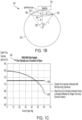
- FIG. 1C illustrates a graph 104 illustrating Earth flux density with respect to scan angle (in degrees) of a satellite.
- the scan angle can also correspond to the "theta" illustrated in FIG. 1B .
- a comparative array element (which can be part of a typical satellite) output is illustrated by curve 106 while a phased array of elements according to examples as described herein are illustrated by line 108. That is, the satellite 142 can emit the array element radiation pattern to generate the Earth flux density of line 108.
- the comparative array element can have a 3 to 4 dB of roll-off at the edge of coverage in addition to the spreading loss.
- the flux density on the Earth is much lower at the edge of coverage (60 scan angle degrees) as compared to on boresight (0 scan angle degrees).
- the flux density for a given element efficiency is flat and corresponds to around a 3 dB improvement in the average flux density on Earth.
- the line 108 requires less power to generate than the curve 106. That is, an area (e.g., an integral) under the line 108 is less than the area (e.g., an integral) of the curve 106, thus enhancing the efficiency of the satellite 142 and reducing the size and power usage of the satellite 142.
- the line 108 provides a consistent flux density throughout a coverage area.
- the satellite 142 generates the array element radiation pattern to provide an Earth flux density that corresponds to the line 108. Doing so can provide a more consistent experience. For example, since the flux density is consistent throughout the line 108, a ground antenna (that can be moving) will operate with the same signal strength throughout the entire coverage area 102 of the satellite 142 without requiring compensation by the ground antenna.
- ground antennas are reciprocal and are dictated by the least sensitive power path (which is usually at the perimeter 146 of the coverage area 102), the ground antennas do not need as significant transmission power and can be reduced in size and weight, while benefitting from increased energy efficiency since the ground antennas do not need as great power to receive and transmit to the satellite 142.
- the satellite 142 is more efficient by providing the Earth flux density according to the line 108.
- the satellite 142 can be reduced in size and power since the satellite 142 requires less power to operate and is more efficient.
- the satellite 142 can have an amplifier that is reduced in power and weight.
- a typical array element of a typical satellite, that generates an Earth flux density according to the curve 106, can attempt to increase power as gain diminishes with increasing scan angle. Doing so results in increased circuitry, complexity and power.
- FIG. 1D illustrates a directivity versus scan profile 110.
- the directivity versus scan profile 110 can map a scan angle with respect to strength of signal decibels relative to isotropic (dBi) emitted by a satellite from a 1000 KM orbit.
- dBi isotropic
- the directivity versus scan profile 110 is dBi of the array element radiation pattern that is emitted by a satellite with respect to scan angle.
- the satellite 142 can emit an array element radiation pattern having characteristics (e.g., a strength to scan angle) that matches the first curve 112. Doing so results in a radiation flux being generated on the Earth 152.
- satellite 142 generates a signal according to the first curve 112 to provide a uniform radiation flux on the Earth 152 which matches the line 108 ( FIG. 1C ).
- an exemplary array element radiation pattern provides a constant flux density value as a function of scan. On reception, such a gain pattern will receive a constant power from ground stations with identical effective radiated power (ERIP) anywhere on the Earth.
- ERIP effective radiated power
- the first curve 112 increases in strength of signal dBi with scan angle. As illustrated the first curve 112 naturally increases in strength towards the perimeter 146.
- the first curve 112 can be generated by a satellite towards Earth, and the resulting Earth flux density on Earth would be the line 108.
- a comparative satellite generates emit an array element radiation pattern according to second curve 114 that diminishes in dBi with increasing scan angle to result in diminishing and inconsistent Earth flux densities. That is, emission of an array element radiation pattern according to the second curve 114 would result in the Earth flux density of the curve 106 which is inconsistent and degrades performance
- an ideal gain pattern corresponds to the first curve 112 and ranges from -1.5 to +10 or a 11.5 dBi change in gain.
- Such a gain change corresponds to a change in magnification of 3.8.
- FIG. 2 illustrates a cross-section of initial geometry 200 of a feed and satellite antenna.
- the cross-section of initial geometry 200 includes a y-axis that corresponds to height, and an x-axis that corresponds to width.
- This example includes a reflector feed geometry that includes a reflector 258 and a phased array of elements 256 (e.g., a feed array or array elements).
- This example has an on-axis reflector geometry.
- the phased array of elements 256 is designed to scan to 30 degrees from boresight (0 scan angle) with approximately a -3 dBi difference across scan angles. That is, the dBi at the boresight is 3 dBi less than at the scan angle of 30 degrees.
- the phased array of elements 256 emits a ray 252 at an approximate scan angle of 30 degrees.
- the reflector 258 reflects the ray 252 (and other unillustrated rays) towards the Earth to generate an array element radiation pattern. Since the ray 252 strikes the reflector 258 at an angle of 30 degrees, the ray 252 is reflected 30 degrees increasing the scan angle range to 60 degrees (i.e., the angle of reflection is equal to the angle of incidence).
- the reflector 258 can have a starting magnification factor of around -2 to extend the scan range to 60 degrees from boresight.
- the reflector 258 can have a slope of around 15 degrees.
- the reflector 258 is configured to increase the scan angle range by a predetermined amount of degrees (e.g., 30 degrees), and corresponding the shape of the reflector 258 has a slope (e.g., 15 degrees) that is equal to half the amount of the predetermined amount of degrees. Doing so enables the reflector 258 to increase the scan angle range by a specified range.
- a predetermined amount of degrees e.g., 30 degrees
- corresponding the shape of the reflector 258 has a slope (e.g., 15 degrees) that is equal to half the amount of the predetermined amount of degrees. Doing so enables the reflector 258 to increase the scan angle range by a specified range.
- the reflector 258 has an apex at a center portion 258a that is gradually flattened towards the zero width.
- the outer portions 258b have a slope of 15 degrees and protrude from the center portion 258a to reduce or eliminate grating globes.
- the overall shape of the reflector 258 is a substantially inverse parabolic shape near the center and becomes less curved near the edge.
- a spacing of elements of the phased array of elements 256 can be selected to minimize or eliminate grating lobes. That is, if the spacing elements of the phased array of elements 256 are too large relative to a total scan area, grating lobes can occur due to the periodic nature of rays emitted and received by the phased array of elements 256 such that secondary images (aliasing) occur. An increase in scan area of the phased array of elements 256 corresponds to a reduction in spacing of the elements.
- the phased array of elements 256 can have a smaller scan area that is increased by the reflector 258.
- the phased array of elements 256 can have larger distance between the element than other designs, leading to reduced circuitry and complications that arise with elements that are spaced closer together in the other designs. That is, as opposed to designing the elements of the phased array of elements 256 to be spaced apart by 1 ⁇ 2 lambda (as would be case for a 60 degree scan area), the phased array of elements 256 can be designed to be spaced apart by 1 lambda (for a 30 degree scan area that is increased by 30 degrees by the reflector 258). The increased spacing permits larger elements to be utilized in the phased array of elements 256 thereby reducing complicated circuitry that is associated with smaller elements.
- element spacing can be increased for a given coverage region, reducing mutual coupling and increasing the available space to place necessary element electronics.
- an array of elements spaced 1.1 wavelength apart can have a scan region limited to around ⁇ 30 deg due to the grating lobe entering this region at maximum scan.
- An array of elements spaced 1 wavelength apart, illuminating a reflector of magnification -2, will have a grating lobe ⁇ ⁇ 60 degrees from boresight, and can illuminate a field of view normally requiring an array of elements spaces 1 ⁇ 2 wavelength apart.
- Some examples herein include an array of elements spaced 1 wavelength apart feeding a reflector of magnification -2, before shaping, to be used over a ⁇ 60 deg field of view. Relative to such conventional designs, examples as described herein can have less elements additionally due to the negative magnification of the reflector and spacing of the elements.
- FIG. 3 illustrates a diagram 300 of ray densities (paths of electromagnetic radiation) according to some examples.
- a phased array of elements 304 emits rays towards a mirror 302 (e.g., a single on-axis reflector) having an inverse parabolic shape with a local convex.
- the rays are reflected by the mirror 302 to increase the scan angle and reflect towards Earth.
- the mirror 302 naturally focuses more of the rays towards the higher scan angles as a consequence of the angles of the rays that impinge of the mirror 302.
- the ray density increases with increasing scan angle and diminishes with reduced scan angle.
- FIG. 4A shows an axis-symmetric satellite antenna 400.
- a phased array of elements 404 transmit electromagnetic radiation 402 to a reflector 406.
- the reflector 406 reflects the electromagnetic radiation 402 to Earth to generate an array element radiation pattern.
- an excitation of the phased array of elements 404 is set using conjugate field matching to maximize directivity.
- Other phase and amplitude optimization techniques can be used as well and do not result in aperture blockage.
- FIG. 4B illustrates an offset array feed and satellite antenna 420.
- the offset array feed and satellite antenna 420 implements examples as described herein and does not have aperture blockage. With an offset configuration RF performance can be symmetric as described above and with no blockage.
- a phased array of elements 426 projects electromagnetic radiation to the reflector 428 that is reflected as rays 422.
- the process for generation of the electromagnetic radiation to the reflector 428 and reflection thereof is the same for both transmit or receive due to reciprocity.
- the reflector 428 e.g., single off-set reflector
- the processes described herein can be applied to off-set and axis symmetric reflectors.
- the process can be applied to reflectors with different magnification factors as well.
- FIG. 5A illustrates a graph 500 of an element radiation pattern 502.
- the graph 500 amplitude and a scan angle (theta) that is used to feed a reflector.
- the element radiation pattern 502 can have around 1 wavelength in diameter.
- the axis-symmetric satellite antenna can generate the element radiation pattern 502.
- FIG. 5B illustrates a graph 510 of an element radiation pattern 516.
- the graph 510 amplitude and a scan angle (theta) that is used to feed a reflector.
- the element radiation pattern 512 can have around 1 wavelength in diameter.
- the offset array feed and satellite antenna 420 can generate the element radiation pattern 516.
- FIG. 6 illustrates a graph 600 of scan angle and composite pattern showing gain with array excitation enhanced to scan to each direction shown.
- Curve 602 corresponds to 253 elements with 1 ⁇ 2 wavelength spaced array elements feeding a shaped reflector.
- Curve 604 corresponds to 253 elements with 1 wavelength spaced array elements feeding a shaped reflector.
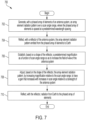
- FIG. 7 shows a method 700 of array element radiation pattern generation.
- the method 700 is generally implemented by any of the examples described herein.
- the 700 is implemented at least partly in one or more modules as a set of logic instructions stored in a non-transitory machine- or computer-readable storage medium such as random access memory (RAM), read only memory (ROM), programmable ROM (PROM), firmware, flash memory, etc., in configurable logic such as, for example, programmable logic arrays (PLAs), field programmable gate arrays (FPGAs), complex programmable logic devices (CPLDs), in fixed-functionality logic hardware using circuit technology such as, for example, application specific integrated circuit (ASIC), complementary metal oxide semiconductor (CMOS) or transistor-transistor logic (TTL) technology, or any combination thereof.
- ASIC application specific integrated circuit
- CMOS complementary metal oxide semiconductor
- TTL transistor-transistor logic
- Illustrated processing block 702 generates, with a phased array of elements of an antenna system, an array element radiation pattern over a scan angle range, where the phased array of elements is spaced at a predetermined wavelength spacing.
- Illustrated processing block 704 reflects, with a reflector of the antenna system, the array element radiation pattern emitted from the phased array of elements to Earth.
- Illustrated processing block 706 establishes, based on a shape of the reflector, a predetermined magnification as a function of scan angle range so as to increase the field-of-view of the antenna system.
- Illustrated processing block 708 adjusts, based on the shape of the reflector, the array element radiation pattern, by increasing magnification relative to the scan angle range, to have a gain that increases with increases in scan angle relative to a boresight of the antenna system.
- Illustrated processing block 710 reflects, with the reflector, radiation from Earth to the phased array of elements.
- the predetermined magnification is within a range from a negative magnification of -3 for small scan angles (e.g., from -half the maximum scan angle to half the maximum scan angle) up to a positive magnification of +2 for large scan angles (angles greater than half the maximum scan angle to the maximum scan angle, and angles less than -half the maximum scan angle to a -maximum scan angle), and is a function of scan angle range. For example, if the maximum scan angle is 60 degrees, the small scan angles would include from -30 to 30 degrees and the large scan angles would include -60 to -31 degrees and 31 to 60 degrees.
- the method 700 includes increasing, with the reflector, the scan angle range by a predetermined amount of degrees, wherein the shape of the reflector has a slope that is equal to half the amount of the predetermined amount of degrees for small scan angles (e.g., from -half the maximum scan angle to half the maximum scan angle) and transitions to less negative magnification at wider scan angles (angles greater than half the maximum scan angle to the maximum scan angle, and angles less than -half the maximum scan angle to a -maximum scan angle). For example, if the maximum scan angle is 60 degrees, the small scan angles would include from -30 to 30 degrees and the large scan angles would include -60 to -31 degrees and 31 to 60 degrees.
- the reflector is a single off-set reflector.
- the reflector is a single on-axis reflector.
- the predetermined wavelength spacing that is configured for scanning from a -30 degree scan angle from the boresight to a 30 degree scan angle from the boresight, and the reflector has a predetermined magnification of -2 near the center or less to extend the -30 degree scan angle to a -60 degree scan angle from the boresight and the 30 degree scan angle to a 60 degree scan angle from the boresight.
- the phased array of elements are spaced at one wavelength apart.
- the predetermined wavelength spacing is configured for scanning from a -20 degree scan angle from the boresight to a 20 degree scan angle from the boresight, and the reflector has a predetermined magnification of -3 or less to extend the -20 degree scan angle to a -60 degree scan angle from the boresight, and extend the 20 degree scan angle to a 60 degree scan angle from the boresight.
- the method 700 includes reflecting, with the reflector, the array element radiation pattern to have a first gain in a direction of Earth perimeter relative to the antenna system, and a second gain in a direction of Earth nadir relative to the antenna system, wherein the first gain is greater than the second gain.
- the reflector has a substantially inverse parabolic shape, and the array element radiation pattern reflected by the reflector has a substantially uniform flux density on the Earth.
- An antenna system comprising:
- Clause 2 The antenna system of clause 1, wherein the predetermined magnification is within a range from a negative magnification of -3 for small scan angles, up to a positive magnification of +2 for large scan angles at an edge of coverage.
- Clause 4 The antenna system of any of the preceding Clauses, wherein the reflector is a single off-set reflector.
- Clause 7 The antenna of Clause 6, wherein the phased array of elements are spaced at one wavelength apart.
- Clause 12 The method of Clause 11, wherein the predetermined magnification is within a range from a negative magnification of -3 for small scan angles up to a positive magnification of +2 for large scan angles, and is a function of scan angle range.
- Clause 13 The method of Clause 11 or 12, further comprising: increasing, with the reflector, the scan angle range by a predetermined amount of degrees, wherein the shape of the reflector has a slope that is equal to half the amount of the predetermined amount of degrees for small scan angles and transitions to less negative magnification at wider scan angles.
- Clause 14 The method of any of Clauses 11 to 13, wherein the reflector is a single off-set reflector.
- Clause 15 The method of any of Clauses 11 to 14, wherein the reflector is a single on-axis reflector.
- Clause 16 The method of any of Clauses 11 to 15, wherein:
- Clause 17 The method of Clause 16, wherein the phased array of elements are spaced at one wavelength apart.
- Clause 19 The method of any of Clauses 11 to 18, further comprising: reflecting, with the reflector, the array element radiation pattern to have a first gain in a direction of Earth perimeter relative to the antenna system, and a second gain in a direction of Earth nadir relative to the antenna system, wherein the first gain is greater than the second gain.
- Example sizes/models/values/ranges can have been given, although examples are not limited to the same. As manufacturing techniques (e.g., photolithography) mature over time, it is expected that devices of smaller size could be manufactured.
- well known power/ground connections to IC chips and other components can or cannot be shown within the figures, for simplicity of illustration and discussion, and so as not to obscure certain aspects of the examples.
- arrangements can be shown in block diagram form in order to avoid obscuring examples, and also in view of the fact that specifics with respect to implementation of such block diagram arrangements are highly dependent upon the computing system within which the example is to be implemented, i.e., such specifics should be well within purview of one skilled in the art.
- Coupled can be used herein to refer to any type of relationship, direct or indirect, between the components in question, and can apply to electrical, mechanical, fluid, optical, electromagnetic, electromechanical or other connections.
- first”, second, etc. can be used herein only to facilitate discussion, and carry no particular temporal or chronological significance unless otherwise indicated.
Landscapes
- Physics & Mathematics (AREA)
- Engineering & Computer Science (AREA)
- Astronomy & Astrophysics (AREA)
- General Physics & Mathematics (AREA)
- Remote Sensing (AREA)
- Aviation & Aerospace Engineering (AREA)
- Electromagnetism (AREA)
- Aerials With Secondary Devices (AREA)
- Variable-Direction Aerials And Aerial Arrays (AREA)
- Details Of Aerials (AREA)
Abstract
Description
- Examples generally relate to generating array element radiation patterns with an antenna system over a scan range to compensate for length of travel of the array element radiation patterns. More particularly, examples relate to increasing a gain of the array element radiation patterns as a scan angle relative to a boresight of the antenna system increases.
- Communication satellites are employed to receive electromagnetic signals from ground components, process the signals and/or retransmit the signals to other ground components. The signals contain various types of information ranging from voice, video, data, images, etc. for communication between various ground components through the satellite. The satellite can thus both receive information and transmit information.
- Satellites employ antennas to transmit and receive signals. Antennas have the ability to direct the signals to a specific location and the ability to tune to signals emanating from a specific location. Antennas can transmit signals having specific frequencies to a specific location by focusing the signals into a radiation pattern. Similarly, antennas tune to the same radiation pattern to receive signals with the given frequencies emanating from the specific location. The gain of an antenna is the measure of the ability of an antenna to increase the power to a given area by reducing the power to other areas (e.g., a sensitivity of the antenna). The gain can be related to the size of the radiation pattern and is related to a data rate that the antenna can support (e.g., the higher the gain the higher the data rate).
- In accordance with one or more examples, an antenna system comprises a phased array of elements spaced at a predetermined wavelength spacing, the phased array of elements being configured to generate an array element radiation pattern over a scan angle range. The antenna system further comprises a reflector to reflect the array element radiation pattern from the phased array of elements to Earth, the reflector having a shape configured to establish a predetermined magnification as a function of scan angle range so as to increase the field-of-view of the antenna system, where the shape of the reflector is further configured to adjust the array element radiation pattern, by increasing magnification relative to the scan angle range, to have a gain that increases with increases in scan angle relative to a boresight of the antenna system. The phased array of elements is positioned at a feed location to receive radiation from Earth reflected by the reflector.
- In accordance with one or more examples, a method comprises generating, with a phased array of elements of an antenna system, an array element radiation pattern over a scan angle range, wherein the phased array of elements is spaced at a predetermined wavelength spacing, and reflecting, with a reflector of the antenna system, the array element radiation pattern emitted from the phased array of elements to Earth. The method further comprises establishing, based on the shape of the reflector, a predetermined magnification as a function of scan angle range so as to increase the field-of-view of the antenna system, adjusting, based on the shape of the reflector, the array element radiation pattern, by increasing magnification relative to the scan angle range, to have a gain that increases with increases in scan angle relative to a boresight of the antenna system and reflecting, with the reflector, radiation from Earth to the phased array of elements.
- The various advantages of the examples will become apparent to one skilled in the art by reading the following specification and appended claims, and by referencing the following drawings, in which:
-
FIG. 1A is an example of a satellite transmitting an array element radiation pattern; -
FIG. 1B is an example of a coverage area of the satellite; -
FIG. 1C is an example of a graph illustrating Earth flux density with respect to scan angle; -
FIG. 1D is an example of a directivity versus scan profile; -
FIG. 2 is an example of a cross-section of initial geometry of a feed and satellite antenna; -
FIG. 3 is an example of a diagram of ray densities; -
FIG. 4A is an example of an axis-symmetric satellite antenna; -
FIG. 4B is an example of an offset array feed and satellite antenna; -
FIG. 5A is an example of a graph of an element radiation pattern of an axis-symmetric satellite antenna configuration; -
FIG. 5B is an example of a graph of an element radiation pattern of an offset satellite antenna configuration; -
FIG. 6 is an example of a graph of scan angle and composite pattern showing gain with array excitation enhanced to scan to each direction shown; and -
FIG. 7 shows a method of array element radiation pattern generation according to some examples. -
FIG. 1A illustrates a satellite and Earthgeometry 140 that includes a satellite 142 (e.g., an antenna system including a phased array of elements to generate an array element radiation pattern and a reflector to reflect the array element radiation pattern). Thesatellite 142 can transmit signals to an area on a planetary body such as Earth 152. Paths of the signals (e.g., electromagnetic waves) from thesatellite 142 vary in distance due to the spherical nature of the Earth 152. In a typical satellite, such different path lengths result in different flux densities throughout the area resulting in inconsistent performance throughout the area and particularly degraded performance at aperimeter 146 of the area. Thesatellite 142 of present examples provides consistent flux density throughout the area resulting in an enhanced performance that is more efficient (e.g., less power and hardware). - In this example, the
satellite 142 transmits an electromagnetic radiation pattern (which can also be referred to as an array element radiation pattern) to the Earth 152. As illustrated, a shape of the Earth 152 is spherical thus resulting in different distances between thesatellite 142 and positions on the Earth 152. For example, a path length D0 between thesatellite 142 and subsatellite point 154 (e.g., a nadir) of the Earth 152 is less than a path length D1 between thesatellite 142 and aperimeter 146 of the Earth 152. Thesubsatellite point 154 is at a center of coverage area 102 (an illumination area demarcated by the dashed line) and a boresight of thesatellite 142. The increase in the path length D1 relative to the path length D0 results in increased spreading of radio-frequency (RF) path loss to targets at theperimeter 146 than at thesubsatellite point 154. Furthermore, power loss increases as the path length increases. - Thus, in typical satellites, the flux density at the edge of
coverage area 102 at theperimeter 146 is less than flux density at the center ofcoverage area 102 atsubsatellite point 154. To address the above, thesatellite 142 described herein adjusts, with a reflector of thesatellite 142, the array element radiation pattern to have a gain that increases as a scan angle relative to a boresight of thesatellite 142 increases. The scan angle can be defined relative to boresight (e.g., axis of maximum gain) of thesatellite 142. For example, a 0 degree scan angle would be aligned with the boresight while a 60 degree scan angle would form a 60 degree angle with the boresight. - The above can also compensate for the greater area at the
perimeter 146. For example, a coverage at theperimeter 146 is larger than an area at thesubsatellite point 154. For example, inFIG. 1B anentire coverage area 102 of the satellite is illustrated as a spherical cap. Thecoverage area 102 increases in size with increasing distance away from thesubsatellite point 154. As shown, the size of thecoverage area 102 at theperimeter 146 is greater than the size of the coverage area at thesubsatellite point 154. That is, the area of the Earth 152 covered for a given scan angle can be determined based on following Equation I:
- In Equation I, the area is "a" of a circular portion of the
coverage area 102 at height h. In Equation I, a2 is a radius of the circular portion at the height h. For example, astraight line 158 is a radius of theEarth 152 and is also oriented towards thesatellite 142. Hypothetically, if thestraight line 158 extended farther out of theEarth 152, thestraight line 158 would intersect thesatellite 142. H2 is a distance (e.g., H) along thestraight line 158 that extends between the circular portion and the surface of theEarth 152. Thus, cross-sections at smaller heights H can have reduced radii and correspondingly smaller areas. - To increase the gain at the
perimeter 146 relative to thesubsatellite point 154, the satellite 142 (e.g., an antenna system) generates, with the phased array of elements, an array element radiation pattern over a scan angle range, where the phased array of elements is spaced at a predetermined wavelength spacing. Thesatellite 142 reflects, with a reflector of thesatellite 142, the array element radiation pattern emitted from the phased array of elements to earth. Thesatellite 142 establishes, based on a shape of the reflector, a predetermined magnification as a function of scan angle range so as to increase the field-of-view of the antenna system and adjusts, based on the shape of the reflector, the array element radiation pattern, by increasing magnification relative to the scan angle range, to have a gain that increases with increases in scan angle relative to a boresight of thesatellite 142. Thesatellite 142 further reflects, with the reflector, radiation from Earth to the phased array of elements. Thus, the gain at the boresight of the antenna at thesubsatellite point 154 is less than at theperimeter 146. In doing so, beams, formed by electromagnetic radiation from thesatellite 142, at theperimeter 146 andsubsatellite point 154 have a similar and/or same size. - In some examples, the predetermined magnification of the
satellite 142 is a negative magnification. The predetermined magnification can be within a range from a negative magnification of -3 for small scan angles (e.g., from -half the maximum scan angle to half the maximum scan angle) up to a positive magnification of +2 for large scan angles (angles greater than half the maximum scan angle to the maximum scan angle, and angles less than -half the maximum scan angle to a -maximum scan angle), and is a function of scan angle range. For example, if the maximum scan angle is 60 degrees, the small scan angles would include from -30 to 30 degrees and the large scan angles would include -60 to -31 degrees and 31 to 60 degrees. In some examples, the negative magnification is adjusted to correspond to gain that would range from -1.5 to +10 or around 11.5 dB change in gain, which corresponds to a change in magnification of 3.8. The magnification factor for an inverted parabolic type surface reflector for the magnification can range -3 to +0.8. The relationship is described by Magnification = -3+10^((gain-gain_max)/20) where "-3" corresponds to the magnification. For a surface that is initially flat, the ideal magnification would range from 0 to +3.8 to provide sufficient gain. - In some examples, the
satellite 142 increases, with the reflector, the scan angle range by a predetermined amount of degrees, where the shape of the reflector has a slope that is equal to half the amount of the predetermined amount of degrees for small scan angles (e.g., from -half the maximum scan angle to half the maximum scan angle) and transitions to less negative magnification at wider scan angles (angles greater than half the maximum scan angle to the maximum scan angle, and angles less than -half the maximum scan angle to a -maximum scan angle). For example, if the maximum scan angle is 60 degrees, the small scan angles would include from -30 to 30 degrees and the large scan angles would include -60 to -31 degrees and 31 to 60 degrees. It is worthwhile to note that the reflector can be an off-set reflector or an on-axis reflector. In some examples, the phased array of elements are spaced at a predetermined wavelength spacing that is configured for scanning from a -30 degree scan angle from the boresight to a 30 degree scan angle from the boresight, and the reflector has a predetermined magnification of -2 (e.g., near the center) to extend the -30 degree scan angle to a -60 degree scan angle from the boresight and the 30 degree scan angle to a 60 degree scan angle from the boresight. - In some examples, the phased array of elements are spaced at one wavelength apart. In some examples, the phased array of elements are spaced at a predetermined wavelength spacing that is configured for scanning from a -20 degree scan angle from the boresight to a 20 degree scan angle from the boresight, and the reflector has a predetermined magnification of -3 (e.g., near the center) to extend the -20 degree scan angle to a -60 degree scan angle from the boresight, and extend the 20 degree scan angle to a 60 degree scan angle from the boresight. In some examples, the
satellite 142 reflects, with the reflector, the array element radiation pattern to have a first gain in a direction of perimeter 146 (which can be referred to as Earth Perimeter) relative to thesatellite 142, and a second gain in a direction of nadir relative to thesatellite 142, where the first gain is greater than the second gain. In some examples, the reflector has a substantially inverse parabolic shape near the center and becomes less curved near the edge, and the array element radiation pattern reflected by the reflector has a substantially uniform flux density (e.g., an amount of flux per unit area) on theEarth 152. In some examples, thesatellite 142 is a low-Earth orbit satellite. -
FIG. 1C illustrates agraph 104 illustrating Earth flux density with respect to scan angle (in degrees) of a satellite. The scan angle can also correspond to the "theta" illustrated inFIG. 1B . A comparative array element (which can be part of a typical satellite) output is illustrated bycurve 106 while a phased array of elements according to examples as described herein are illustrated byline 108. That is, thesatellite 142 can emit the array element radiation pattern to generate the Earth flux density ofline 108. - The comparative array element can have a 3 to 4 dB of roll-off at the edge of coverage in addition to the spreading loss. With the comparative array element, as illustrated in
curve 106, the flux density on the Earth is much lower at the edge of coverage (60 scan angle degrees) as compared to on boresight (0 scan angle degrees). In contrast, in examples as described herein and shown inline 108, the flux density for a given element efficiency is flat and corresponds to around a 3 dB improvement in the average flux density on Earth. Furthermore, theline 108 requires less power to generate than thecurve 106. That is, an area (e.g., an integral) under theline 108 is less than the area (e.g., an integral) of thecurve 106, thus enhancing the efficiency of thesatellite 142 and reducing the size and power usage of thesatellite 142. - Thus, the
line 108 provides a consistent flux density throughout a coverage area. As noted, thesatellite 142 generates the array element radiation pattern to provide an Earth flux density that corresponds to theline 108. Doing so can provide a more consistent experience. For example, since the flux density is consistent throughout theline 108, a ground antenna (that can be moving) will operate with the same signal strength throughout theentire coverage area 102 of thesatellite 142 without requiring compensation by the ground antenna. Furthermore, since ground antennas are reciprocal and are dictated by the least sensitive power path (which is usually at theperimeter 146 of the coverage area 102), the ground antennas do not need as significant transmission power and can be reduced in size and weight, while benefitting from increased energy efficiency since the ground antennas do not need as great power to receive and transmit to thesatellite 142. - Moreover, the
satellite 142 is more efficient by providing the Earth flux density according to theline 108. For example, thesatellite 142 can be reduced in size and power since thesatellite 142 requires less power to operate and is more efficient. For example, thesatellite 142 can have an amplifier that is reduced in power and weight. A typical array element of a typical satellite, that generates an Earth flux density according to thecurve 106, can attempt to increase power as gain diminishes with increasing scan angle. Doing so results in increased circuitry, complexity and power. -
FIG. 1D illustrates a directivity versusscan profile 110. The directivity versusscan profile 110 can map a scan angle with respect to strength of signal decibels relative to isotropic (dBi) emitted by a satellite from a 1000 KM orbit. Thus the directivity versusscan profile 110 is dBi of the array element radiation pattern that is emitted by a satellite with respect to scan angle. - The
satellite 142 can emit an array element radiation pattern having characteristics (e.g., a strength to scan angle) that matches thefirst curve 112. Doing so results in a radiation flux being generated on theEarth 152. In this example,satellite 142 generates a signal according to thefirst curve 112 to provide a uniform radiation flux on theEarth 152 which matches the line 108 (FIG. 1C ). As already noted in the discussion of theline 108, an exemplary array element radiation pattern provides a constant flux density value as a function of scan. On reception, such a gain pattern will receive a constant power from ground stations with identical effective radiated power (ERIP) anywhere on the Earth. Thus, the array element radiation pattern of examples as described herein is shown asfirst curve 112. Thefirst curve 112 increases in strength of signal dBi with scan angle. As illustrated thefirst curve 112 naturally increases in strength towards theperimeter 146. Thefirst curve 112 can be generated by a satellite towards Earth, and the resulting Earth flux density on Earth would be theline 108. - In contrast, in a comparative example, a comparative satellite generates emit an array element radiation pattern according to
second curve 114 that diminishes in dBi with increasing scan angle to result in diminishing and inconsistent Earth flux densities. That is, emission of an array element radiation pattern according to thesecond curve 114 would result in the Earth flux density of thecurve 106 which is inconsistent and degrades performance - Moreover, the approach as described in examples scales for all orbit heights. For orbit heights greater than 100 KM a maximum scan angle can be reduced, but a desired relative pattern increase from boresight to max scan remains similar to as described with respect to
first curve 112. - As illustrated in FIG. ID, an ideal gain pattern corresponds to the
first curve 112 and ranges from -1.5 to +10 or a 11.5 dBi change in gain. Such a gain change corresponds to a change in magnification of 3.8. The magnification factor for the inverted parabolic type surface for the ideal magnification would range from -3 to +0.8 to follow the profile of thefirst curve 112 with the relationship M = -3+10^((gain-gain_max)/20). From a surface of the reflector that is flat (e.g., at a center of the reflector) the ideal magnification would increase from 0 to +3.8 away from the flat surface towards the edges to follow the profile of thefirst curve 112 with the relationship M = 0+10^((gain-gain_max)/20). Thus, a magnification of the reflector can consistently change from a center to an edge to control gain. -
FIG. 2 illustrates a cross-section ofinitial geometry 200 of a feed and satellite antenna. The cross-section ofinitial geometry 200 includes a y-axis that corresponds to height, and an x-axis that corresponds to width. This example includes a reflector feed geometry that includes areflector 258 and a phased array of elements 256 (e.g., a feed array or array elements). This example has an on-axis reflector geometry. The phased array ofelements 256 is designed to scan to 30 degrees from boresight (0 scan angle) with approximately a -3 dBi difference across scan angles. That is, the dBi at the boresight is 3 dBi less than at the scan angle of 30 degrees. The phased array ofelements 256 emits aray 252 at an approximate scan angle of 30 degrees. - The
reflector 258 reflects the ray 252 (and other unillustrated rays) towards the Earth to generate an array element radiation pattern. Since theray 252 strikes thereflector 258 at an angle of 30 degrees, theray 252 is reflected 30 degrees increasing the scan angle range to 60 degrees (i.e., the angle of reflection is equal to the angle of incidence). Thereflector 258 can have a starting magnification factor of around -2 to extend the scan range to 60 degrees from boresight. Thereflector 258 can have a slope of around 15 degrees. That is, thereflector 258 is configured to increase the scan angle range by a predetermined amount of degrees (e.g., 30 degrees), and corresponding the shape of thereflector 258 has a slope (e.g., 15 degrees) that is equal to half the amount of the predetermined amount of degrees. Doing so enables thereflector 258 to increase the scan angle range by a specified range. - In this example, the
reflector 258 has an apex at acenter portion 258a that is gradually flattened towards the zero width. Theouter portions 258b have a slope of 15 degrees and protrude from thecenter portion 258a to reduce or eliminate grating globes. Thus, the overall shape of thereflector 258 is a substantially inverse parabolic shape near the center and becomes less curved near the edge. - A spacing of elements of the phased array of
elements 256 can be selected to minimize or eliminate grating lobes. That is, if the spacing elements of the phased array ofelements 256 are too large relative to a total scan area, grating lobes can occur due to the periodic nature of rays emitted and received by the phased array ofelements 256 such that secondary images (aliasing) occur. An increase in scan area of the phased array ofelements 256 corresponds to a reduction in spacing of the elements. - In examples as described herein, the phased array of
elements 256 can have a smaller scan area that is increased by thereflector 258. Thus, the phased array ofelements 256 can have larger distance between the element than other designs, leading to reduced circuitry and complications that arise with elements that are spaced closer together in the other designs. That is, as opposed to designing the elements of the phased array ofelements 256 to be spaced apart by ½ lambda (as would be case for a 60 degree scan area), the phased array ofelements 256 can be designed to be spaced apart by 1 lambda (for a 30 degree scan area that is increased by 30 degrees by the reflector 258). The increased spacing permits larger elements to be utilized in the phased array ofelements 256 thereby reducing complicated circuitry that is associated with smaller elements. - Thus, element spacing can be increased for a given coverage region, reducing mutual coupling and increasing the available space to place necessary element electronics. For example an array of elements spaced 1.1 wavelength apart can have a scan region limited to around ±30 deg due to the grating lobe entering this region at maximum scan. An array of elements spaced 1 wavelength apart, illuminating a reflector of magnification -2, will have a grating lobe ~ ±60 degrees from boresight, and can illuminate a field of view normally requiring an array of elements spaces ½ wavelength apart. Some examples herein include an array of elements spaced 1 wavelength apart feeding a reflector of magnification -2, before shaping, to be used over a ±60 deg field of view. Relative to such conventional designs, examples as described herein can have less elements additionally due to the negative magnification of the reflector and spacing of the elements.
-
FIG. 3 illustrates a diagram 300 of ray densities (paths of electromagnetic radiation) according to some examples. In this example, a phased array ofelements 304 emits rays towards a mirror 302 (e.g., a single on-axis reflector) having an inverse parabolic shape with a local convex. The rays are reflected by themirror 302 to increase the scan angle and reflect towards Earth. Themirror 302 naturally focuses more of the rays towards the higher scan angles as a consequence of the angles of the rays that impinge of themirror 302. As illustrated, the ray density increases with increasing scan angle and diminishes with reduced scan angle. -
FIG. 4A shows an axis-symmetric satellite antenna 400. A phased array ofelements 404 transmitelectromagnetic radiation 402 to areflector 406. Thereflector 406 reflects theelectromagnetic radiation 402 to Earth to generate an array element radiation pattern. For each scan direction, an excitation of the phased array ofelements 404 is set using conjugate field matching to maximize directivity. Other phase and amplitude optimization techniques can be used as well and do not result in aperture blockage. -
FIG. 4B illustrates an offset array feed andsatellite antenna 420. The offset array feed andsatellite antenna 420 implements examples as described herein and does not have aperture blockage. With an offset configuration RF performance can be symmetric as described above and with no blockage. A phased array ofelements 426 projects electromagnetic radiation to thereflector 428 that is reflected asrays 422. The process for generation of the electromagnetic radiation to thereflector 428 and reflection thereof is the same for both transmit or receive due to reciprocity. The reflector 428 (e.g., single off-set reflector) reflects the electromagnetic radiation into rays that have highest ray density towards the edge and decreasing ray density towards a center. Thus the processes described herein can be applied to off-set and axis symmetric reflectors. The process can be applied to reflectors with different magnification factors as well. -
FIG. 5A illustrates agraph 500 of anelement radiation pattern 502. Thegraph 500 amplitude and a scan angle (theta) that is used to feed a reflector. Theelement radiation pattern 502 can have around 1 wavelength in diameter. The axis-symmetric satellite antenna can generate theelement radiation pattern 502. -
FIG. 5B illustrates agraph 510 of anelement radiation pattern 516. Thegraph 510 amplitude and a scan angle (theta) that is used to feed a reflector. Theelement radiation pattern 512 can have around 1 wavelength in diameter. The offset array feed andsatellite antenna 420 can generate theelement radiation pattern 516. -
FIG. 6 illustrates agraph 600 of scan angle and composite pattern showing gain with array excitation enhanced to scan to each direction shown.Curve 602 corresponds to 253 elements with ½ wavelength spaced array elements feeding a shaped reflector.Curve 604 corresponds to 253 elements with 1 wavelength spaced array elements feeding a shaped reflector. -
FIG. 7 shows amethod 700 of array element radiation pattern generation. Themethod 700 is generally implemented by any of the examples described herein. In an example, the 700 is implemented at least partly in one or more modules as a set of logic instructions stored in a non-transitory machine- or computer-readable storage medium such as random access memory (RAM), read only memory (ROM), programmable ROM (PROM), firmware, flash memory, etc., in configurable logic such as, for example, programmable logic arrays (PLAs), field programmable gate arrays (FPGAs), complex programmable logic devices (CPLDs), in fixed-functionality logic hardware using circuit technology such as, for example, application specific integrated circuit (ASIC), complementary metal oxide semiconductor (CMOS) or transistor-transistor logic (TTL) technology, or any combination thereof. - Illustrated
processing block 702 generates, with a phased array of elements of an antenna system, an array element radiation pattern over a scan angle range, where the phased array of elements is spaced at a predetermined wavelength spacing. Illustratedprocessing block 704 reflects, with a reflector of the antenna system, the array element radiation pattern emitted from the phased array of elements to Earth. Illustratedprocessing block 706 establishes, based on a shape of the reflector, a predetermined magnification as a function of scan angle range so as to increase the field-of-view of the antenna system. Illustratedprocessing block 708 adjusts, based on the shape of the reflector, the array element radiation pattern, by increasing magnification relative to the scan angle range, to have a gain that increases with increases in scan angle relative to a boresight of the antenna system. Illustratedprocessing block 710 reflects, with the reflector, radiation from Earth to the phased array of elements. In some examples, the predetermined magnification is within a range from a negative magnification of -3 for small scan angles (e.g., from -half the maximum scan angle to half the maximum scan angle) up to a positive magnification of +2 for large scan angles (angles greater than half the maximum scan angle to the maximum scan angle, and angles less than -half the maximum scan angle to a -maximum scan angle), and is a function of scan angle range. For example, if the maximum scan angle is 60 degrees, the small scan angles would include from -30 to 30 degrees and the large scan angles would include -60 to -31 degrees and 31 to 60 degrees. - In some examples, the
method 700 includes increasing, with the reflector, the scan angle range by a predetermined amount of degrees, wherein the shape of the reflector has a slope that is equal to half the amount of the predetermined amount of degrees for small scan angles (e.g., from -half the maximum scan angle to half the maximum scan angle) and transitions to less negative magnification at wider scan angles (angles greater than half the maximum scan angle to the maximum scan angle, and angles less than -half the maximum scan angle to a -maximum scan angle). For example, if the maximum scan angle is 60 degrees, the small scan angles would include from -30 to 30 degrees and the large scan angles would include -60 to -31 degrees and 31 to 60 degrees. In some examples, the reflector is a single off-set reflector. In some examples, the reflector is a single on-axis reflector. In some examples, the predetermined wavelength spacing that is configured for scanning from a -30 degree scan angle from the boresight to a 30 degree scan angle from the boresight, and the reflector has a predetermined magnification of -2 near the center or less to extend the -30 degree scan angle to a -60 degree scan angle from the boresight and the 30 degree scan angle to a 60 degree scan angle from the boresight. - In some examples, the phased array of elements are spaced at one wavelength apart. In some examples, the predetermined wavelength spacing is configured for scanning from a -20 degree scan angle from the boresight to a 20 degree scan angle from the boresight, and the reflector has a predetermined magnification of -3 or less to extend the -20 degree scan angle to a -60 degree scan angle from the boresight, and extend the 20 degree scan angle to a 60 degree scan angle from the boresight.
- In some examples, the
method 700 includes reflecting, with the reflector, the array element radiation pattern to have a first gain in a direction of Earth perimeter relative to the antenna system, and a second gain in a direction of Earth nadir relative to the antenna system, wherein the first gain is greater than the second gain. In some examples, the reflector has a substantially inverse parabolic shape, and the array element radiation pattern reflected by the reflector has a substantially uniform flux density on the Earth. - Further, the disclosure comprises additional examples as detailed in the following clauses below.
-
Clause 1. An antenna system comprising: - a phased array of elements spaced at a predetermined wavelength spacing, the phased array of elements being configured to generate an array element radiation pattern over a scan angle range; and
- a reflector to reflect the array element radiation pattern from the phased array of elements to earth, the reflector having a shape configured to establish a predetermined magnification as a function of scan angle range so as to increase a field-of-view of the antenna system, wherein the shape of the reflector is further configured to adjust the array element radiation pattern, by increasing magnification relative to the scan angle range, to have a gain that increases with increases in scan angle relative to a boresight of the antenna system,
- wherein the phased array of elements is positioned at a feed location to receive radiation from Earth reflected by the reflector.
-
Clause 2. The antenna system ofclause 1, wherein the predetermined magnification is within a range from a negative magnification of -3 for small scan angles, up to a positive magnification of +2 for large scan angles at an edge of coverage. -
Clause 3. The antenna system ofClause - the reflector is configured to increase the scan angle range by a predetermined amount of degrees; and
- the shape of the reflector has a slope that is equal to half the predetermined amount of degrees for small scan angles and transitions to less negative magnification at wider scan angles.
- Clause 4. The antenna system of any of the preceding Clauses, wherein the reflector is a single off-set reflector.
- Clause 5. The antenna system of any of the preceding Clauses, wherein the reflector is a single on-axis reflector.
- Clause 6. The antenna system of any of the preceding Clauses, wherein:
- the predetermined wavelength spacing is configured for scanning from a -30 degree scan angle from the boresight to a 30 degree scan angle from the boresight; and
- the reflector has a predetermined magnification of -2 near the center of the antenna system to extend the -30 degree scan angle to a -60 degree scan angle from the boresight and the 30 degree scan angle to a 60 degree scan angle from the boresight.
- Clause 7. The antenna of Clause 6, wherein the phased array of elements are spaced at one wavelength apart.
- Clause 8. The antenna of any of the preceding Clauses, wherein:
- the predetermined wavelength spacing that is configured for scanning from a -20 degree scan angle from the boresight to a 20 degree scan angle from the boresight; and
- the reflector has a predetermined magnification of -3 near the center to extend the -20 degree scan angle to a -60 degree scan angle from the boresight, and extend the 20 degree scan angle to a 60 degree scan angle from the boresight.
- Clause 9. The antenna system of any of the preceding Clauses,wherein:
- the array element radiation pattern reflected by the reflector has a first gain in a direction of Earth perimeter relative to the antenna system, and a second gain in a direction of Earth nadir relative to the antenna system; and
- the first gain is greater than the second gain.
-
Clause 10. The antenna of any of the preceding Clauses, wherein: - the reflector has a substantially inverse parabolic shape near the center and is less curved near an edge; and
- the array element radiation pattern reflected by the reflector has a substantially uniform flux density on the Earth.
- Clause 11. A method comprising:
- generating, with a phased array of elements of an antenna system, an array element radiation pattern over a scan angle range, wherein the phased array of elements is spaced at a predetermined wavelength spacing;
- reflecting, with a reflector of the antenna system, the array element radiation pattern emitted from the phased array of elements to Earth;
- establishing, based on a shape of the reflector, a predetermined magnification as a function of scan angle range so as to increase a field-of-view of the antenna system;
- adjusting, based on the shape of the reflector, the array element radiation pattern, by increasing magnification relative to the scan angle range, to have a gain that increases with increases in scan angle relative to a boresight of the antenna system; and
- reflecting, with the reflector, radiation from Earth to the phased array of elements.
- Clause 12. The method of Clause 11, wherein the predetermined magnification is within a range from a negative magnification of -3 for small scan angles up to a positive magnification of +2 for large scan angles, and is a function of scan angle range.
- Clause 13. The method of Clause 11 or 12, further comprising:
increasing, with the reflector, the scan angle range by a predetermined amount of degrees, wherein the shape of the reflector has a slope that is equal to half the amount of the predetermined amount of degrees for small scan angles and transitions to less negative magnification at wider scan angles. - Clause 14. The method of any of Clauses 11 to 13, wherein the reflector is a single off-set reflector.
- Clause 15. The method of any of Clauses 11 to 14, wherein the reflector is a single on-axis reflector.
- Clause 16. The method of any of Clauses 11 to 15, wherein:
- the predetermined wavelength spacing that is configured for scanning from a - 30 degree scan angle from the boresight to a 30 degree scan angle from the boresight; and
- the reflector has a predetermined magnification of -2 near the center or less to extend the -30 degree scan angle to a -60 degree scan angle from the boresight and the 30 degree scan angle to a 60 degree scan angle from the boresight.
- Clause 17. The method of Clause 16, wherein the phased array of elements are spaced at one wavelength apart.
- Clause 18. The method of any of Clauses 11 to 17, wherein:
- the predetermined wavelength spacing that is configured for scanning from a - 20 degree scan angle from the boresight to a 20 degree scan angle from the boresight; and
- the reflector has a predetermined magnification of -3 or less to extend the -20 degree scan angle to a -60 degree scan angle from the boresight, and extend the 20 degree scan angle to a 60 degree scan angle from the boresight.
- Clause 19. The method of any of Clauses 11 to 18, further comprising:
reflecting, with the reflector, the array element radiation pattern to have a first gain in a direction of Earth perimeter relative to the antenna system, and a second gain in a direction of Earth nadir relative to the antenna system, wherein the first gain is greater than the second gain. -
Clause 20. The method of any of Clauses 11 to 19, wherein: - the reflector has a substantially inverse parabolic shape; and
- the array element radiation pattern reflected by the reflector has a substantially uniform flux density on the Earth.
- Example sizes/models/values/ranges can have been given, although examples are not limited to the same. As manufacturing techniques (e.g., photolithography) mature over time, it is expected that devices of smaller size could be manufactured. In addition, well known power/ground connections to IC chips and other components can or cannot be shown within the figures, for simplicity of illustration and discussion, and so as not to obscure certain aspects of the examples. Further, arrangements can be shown in block diagram form in order to avoid obscuring examples, and also in view of the fact that specifics with respect to implementation of such block diagram arrangements are highly dependent upon the computing system within which the example is to be implemented, i.e., such specifics should be well within purview of one skilled in the art. Where specific details (e.g., circuits) are set forth in order to describe example examples, it should be apparent to one skilled in the art that examples can be practiced without, or with variation of, these specific details. The description is thus to be regarded as illustrative instead of limiting.
- The term "coupled" can be used herein to refer to any type of relationship, direct or indirect, between the components in question, and can apply to electrical, mechanical, fluid, optical, electromagnetic, electromechanical or other connections. In addition, the terms "first", "second", etc. can be used herein only to facilitate discussion, and carry no particular temporal or chronological significance unless otherwise indicated.
- As used in this application and in the claims, a list of items joined by the term "one or more of' can mean any combination of the listed terms. For example, the phrases "one or more of A, B or C" can mean A; B; C; A and B; A and C; B and C; or A, B and C.
- Those skilled in the art will appreciate from the foregoing description that the broad techniques of the examples can be implemented in a variety of forms. Therefore, while the examples have been described in connection with particular examples thereof, the true scope of the examples should not be so limited since other modifications will become apparent to the skilled practitioner upon a study of the drawings, specification, and following claims.
Claims (15)
- An antenna system (142) comprising:a phased array of elements (256, 304, 404, 426) spaced at a predetermined wavelength spacing, the phased array of elements (256, 304, 404, 426) being configured to generate an array element radiation pattern over a scan angle range; anda reflector (258, 406, 428, 302) to reflect the array element radiation pattern from the phased array of elements (256, 304, 404, 426) to earth, the reflector (258, 406, 428, 302) having a shape configured to establish a predetermined magnification as a function of scan angle range so as to increase a field-of-view of the antenna system (142), wherein the shape of the reflector (258, 406, 428, 302) is further configured to adjust the array element radiation pattern, by increasing magnification relative to the scan angle range, to have a gain that increases with increases in scan angle relative to a boresight of the antenna system (142),wherein the phased array of elements (256, 304, 404, 426) is positioned at a feed location to receive radiation from Earth reflected by the reflector (258, 406, 428, 302).
- The antenna system (142) of claim 1, wherein the predetermined magnification is within a range from a negative magnification of -3 for small scan angles, up to a positive magnification of +2 for large scan angles at an edge of coverage.
- The antenna system (142) of any of claims 1 to 2, wherein:the reflector (258, 406, 428, 302) is configured to increase the scan angle range by a predetermined amount of degrees; andthe shape of the reflector (258, 406, 428, 302) has a slope that is equal to half the predetermined amount of degrees for small scan angles and transitions to less negative magnification at wider scan angles.
- The antenna system (142) of any of claims 1 to 3, wherein the reflector (258, 406, 428, 302) is one of a single off-set reflector (428) and a single on-axis reflector (302).
- The antenna system (142) of any of claims 1 to 4, wherein:the predetermined wavelength spacing is configured for scanning from a -30 degree scan angle from the boresight to a 30 degree scan angle from the boresight; andthe reflector (258, 406, 428, 302) has a predetermined magnification of -2 near the center of the antenna system (142) to extend the -30 degree scan angle to a -60 degree scan angle from the boresight and the 30 degree scan angle to a 60 degree scan angle from the boresight.
- The antenna of claim 5, wherein the phased array of elements (256, 304, 404, 426) are spaced at one wavelength apart.
- The antenna of any of claims 1 to 4, wherein:the predetermined wavelength spacing that is configured for scanning from a -20 degree scan angle from the boresight to a 20 degree scan angle from the boresight; andthe reflector (258, 406, 428, 302) has a predetermined magnification of -3 near the center to extend the -20 degree scan angle to a -60 degree scan angle from the boresight, and extend the 20 degree scan angle to a 60 degree scan angle from the boresight.
- The antenna system (142) of any of claims 1 to 7,wherein:the array element radiation pattern reflected by the reflector (258, 406, 428, 302) has a first gain in a direction of Earth perimeter relative to the antenna system (142), and a second gain in a direction of Earth nadir relative to the antenna system (142); andthe first gain is greater than the second gain.
- The antenna of any of claims 1 to 8, wherein:the reflector (258, 406, 428, 302) has a substantially inverse parabolic shape near the center and is less curved near an edge; andthe array element radiation pattern reflected by the reflector (258, 406, 428, 302) has a substantially uniform flux density on the Earth.
- A method comprising:generating, with a phased array of elements (256, 304, 404, 426) of an antenna system (142), an array element radiation pattern over a scan angle range, wherein the phased array of elements (256, 304, 404, 426) is spaced at a predetermined wavelength spacing;reflecting, with a reflector (258, 406, 428, 302) of the antenna system (142), the array element radiation pattern emitted from the phased array of elements (256, 304, 404, 426) to Earth;establishing, based on a shape of the reflector (258, 406, 428, 302), a predetermined magnification as a function of scan angle range so as to increase a field-of-view of the antenna system (142);adjusting, based on the shape of the reflector (258, 406, 428, 302), the array element radiation pattern, by increasing magnification relative to the scan angle range, to have a gain that increases with increases in scan angle relative to a boresight of the antenna system (142); andreflecting, with the reflector (258, 406, 428, 302), radiation from Earth to the phased array of elements (256, 304, 404, 426).
- The method of claim 10, wherein the predetermined magnification is within a range from a negative magnification of -3 for small scan angles up to a positive magnification of +2 for large scan angles, and is a function of scan angle range.
- The method of claim 10 or 11, further comprising:
increasing, with the reflector (258, 406, 428, 302), the scan angle range by a predetermined amount of degrees, wherein the shape of the reflector (258, 406, 428, 302) has a slope that is equal to half the amount of the predetermined amount of degrees for small scan angles and transitions to less negative magnification at wider scan angles. - The method of claim 10, 11 or 12, wherein the reflector (258, 406, 428, 302) is formed as one of a single off-set reflector (302) and a single on-axis reflector (428).
- The method of any of claims 10 to 13, wherein:the predetermined wavelength spacing that is configured for scanning from a -30 degree scan angle from the boresight to a 30 degree scan angle from the boresight; andthe reflector (258, 406, 428, 302) has a predetermined magnification of -2 near the center or less to extend the -30 degree scan angle to a -60 degree scan angle from the boresight and the 30 degree scan angle to a 60 degree scan angle from the boresight.
- The method of claim 14, wherein the phased array of elements (256, 304, 404, 426) are spaced at one wavelength apart.
Applications Claiming Priority (1)
| Application Number | Priority Date | Filing Date | Title |
|---|---|---|---|
| US17/554,876 US11909126B2 (en) | 2021-12-17 | 2021-12-17 | Optical system for enhanced wide scan capability of array antennas |
Publications (2)
| Publication Number | Publication Date |
|---|---|
| EP4199252A1 true EP4199252A1 (en) | 2023-06-21 |
| EP4199252B1 EP4199252B1 (en) | 2025-09-10 |
Family
ID=83996212
Family Applications (1)
| Application Number | Title | Priority Date | Filing Date |
|---|---|---|---|
| EP22203667.5A Active EP4199252B1 (en) | 2021-12-17 | 2022-10-25 | Optical system for enhanced wide scan capability of array antennas |
Country Status (4)
| Country | Link |
|---|---|
| US (1) | US11909126B2 (en) |
| EP (1) | EP4199252B1 (en) |
| JP (1) | JP2023090698A (en) |
| CN (1) | CN116266676A (en) |
Citations (1)
| Publication number | Priority date | Publication date | Assignee | Title |
|---|---|---|---|---|
| JP2006242752A (en) * | 2005-03-03 | 2006-09-14 | Nippon Telegr & Teleph Corp <Ntt> | Directional error compensation method and apparatus for array-fed reflector multi-beam antenna |
Family Cites Families (9)
| Publication number | Priority date | Publication date | Assignee | Title |
|---|---|---|---|---|
| US3541553A (en) * | 1968-03-27 | 1970-11-17 | Rca Corp | Satellite communications systems |
| FR2653941B1 (en) * | 1989-10-31 | 1992-02-28 | Thomson Lgt | MULTIFOCAL RECEPTION ANTENNA WITH SINGLE POINT DIRECTION FOR MULTIPLE SATELLITES. |
| DE19814048A1 (en) * | 1998-03-30 | 1999-10-14 | Sts Systemtechnik Schwerin Gmb | Planar multi-patch, multi-range antenna with key-shaped directional diagram for low earth orbit satellites |
| US6633264B2 (en) * | 2000-12-21 | 2003-10-14 | Lockheed Martin Corporation | Earth coverage reflector antenna for geosynchronous spacecraft |
| CN106471697A (en) * | 2015-12-16 | 2017-03-01 | 广东欧珀移动通信有限公司 | Method, device, power adapter and mobile terminal for controlling charging |
| RU2741489C1 (en) * | 2017-04-10 | 2021-01-26 | Виасат, Инк. | Adjustment of coverage area for adaptation of satellite communication |
| US10658756B1 (en) * | 2017-12-28 | 2020-05-19 | United States Of America As Represented By The Administrator Of Nasa | Earth coverage antenna system for Ka-band communication |
| IT202000002563A1 (en) * | 2020-02-10 | 2021-08-10 | Telespazio Spa | MULTI-BEAM REFLECTOR ANTENNA FOR SATELLITE APPLICATIONS |
| KR20230104914A (en) * | 2020-11-13 | 2023-07-11 | 비아셋, 인크 | Multiple Static Synthetic Aperture Radar with Low Orbit Acquisition |
-
2021
- 2021-12-17 US US17/554,876 patent/US11909126B2/en active Active
-
2022
- 2022-10-25 EP EP22203667.5A patent/EP4199252B1/en active Active
- 2022-11-25 CN CN202211488778.2A patent/CN116266676A/en active Pending
- 2022-12-19 JP JP2022201776A patent/JP2023090698A/en active Pending
Patent Citations (1)
| Publication number | Priority date | Publication date | Assignee | Title |
|---|---|---|---|---|
| JP2006242752A (en) * | 2005-03-03 | 2006-09-14 | Nippon Telegr & Teleph Corp <Ntt> | Directional error compensation method and apparatus for array-fed reflector multi-beam antenna |
Non-Patent Citations (1)
| Title |
|---|
| ROMERO-PENA J SAMUEL ET AL: "Irregular MultiFocal Reflector for Efficient mmWave Propagation in Indoor Enviroments", 2020 14TH EUROPEAN CONFERENCE ON ANTENNAS AND PROPAGATION (EUCAP), EURAAP, 15 March 2020 (2020-03-15), pages 1 - 5, XP033789571, DOI: 10.23919/EUCAP48036.2020.9136074 * |
Also Published As
| Publication number | Publication date |
|---|---|
| JP2023090698A (en) | 2023-06-29 |
| EP4199252B1 (en) | 2025-09-10 |
| CN116266676A (en) | 2023-06-20 |
| US20230198142A1 (en) | 2023-06-22 |
| US11909126B2 (en) | 2024-02-20 |
Similar Documents
| Publication | Publication Date | Title |
|---|---|---|
| RU2494506C1 (en) | Electronic beam scanning lens antenna | |
| US6723912B2 (en) | Space photovoltaic power generation system | |
| US6441793B1 (en) | Method and apparatus for wireless communications and sensing utilizing a non-collimating lens | |
| US9478861B2 (en) | Dual-band multiple beam reflector antenna for broadband satellites | |
| EP3005482B1 (en) | Antenna for multiple frequency bands | |
| US10566698B2 (en) | Multifocal phased array fed reflector antenna | |
| EP0476131A1 (en) | Electromagnetic antenna collimator | |
| US4145695A (en) | Launcher reflectors for correcting for astigmatism in off-axis fed reflector antennas | |
| EP1041672A1 (en) | Multimode, multi-step antenna feed horn | |
| EP0168904B1 (en) | Offset-fed dual reflector antenna | |
| WO2019170541A1 (en) | Extreme scanning focal-plane arrays using a double-reflector concept with uniform array illumination | |
| EP4199252B1 (en) | Optical system for enhanced wide scan capability of array antennas | |
| US3216018A (en) | Wide angle horn feed closely spaced to main reflector | |
| US6882323B2 (en) | Multi-beam antenna system with shaped reflector for generating flat beams | |
| US11791562B2 (en) | Ring focus antenna system with an ultra-wide bandwidth | |
| JP3925494B2 (en) | Radio wave lens antenna device | |
| JP3808536B2 (en) | Aperture antenna | |
| US6633264B2 (en) | Earth coverage reflector antenna for geosynchronous spacecraft | |
| US20020126063A1 (en) | Rectangular paraboloid truncation wall | |
| US12592495B2 (en) | Systems and methods for mitigating interference from satellite gateway antenna | |
| US9543659B2 (en) | Reflector antenna device | |
| JP2600565B2 (en) | Multi-beam antenna device | |
| JPH0766625A (en) | Multi-beam antenna | |
| JP2021118480A (en) | Reflector antenna | |
| JPH10215118A (en) | Aperture antenna |
Legal Events
| Date | Code | Title | Description |
|---|---|---|---|
| PUAI | Public reference made under article 153(3) epc to a published international application that has entered the european phase |
Free format text: ORIGINAL CODE: 0009012 |
|
| STAA | Information on the status of an ep patent application or granted ep patent |
Free format text: STATUS: THE APPLICATION HAS BEEN PUBLISHED |
|
| AK | Designated contracting states |
Kind code of ref document: A1 Designated state(s): AL AT BE BG CH CY CZ DE DK EE ES FI FR GB GR HR HU IE IS IT LI LT LU LV MC ME MK MT NL NO PL PT RO RS SE SI SK SM TR |
|
| STAA | Information on the status of an ep patent application or granted ep patent |
Free format text: STATUS: REQUEST FOR EXAMINATION WAS MADE |
|
| 17P | Request for examination filed |
Effective date: 20231110 |
|
| RBV | Designated contracting states (corrected) |
Designated state(s): AL AT BE BG CH CY CZ DE DK EE ES FI FR GB GR HR HU IE IS IT LI LT LU LV MC ME MK MT NL NO PL PT RO RS SE SI SK SM TR |
|
| GRAP | Despatch of communication of intention to grant a patent |
Free format text: ORIGINAL CODE: EPIDOSNIGR1 |
|
| STAA | Information on the status of an ep patent application or granted ep patent |
Free format text: STATUS: GRANT OF PATENT IS INTENDED |
|
| RIC1 | Information provided on ipc code assigned before grant |
Ipc: H01Q 15/14 20060101ALI20250131BHEP Ipc: H01Q 3/34 20060101ALI20250131BHEP Ipc: H01Q 1/28 20060101AFI20250131BHEP |
|
| INTG | Intention to grant announced |
Effective date: 20250227 |
|
| P01 | Opt-out of the competence of the unified patent court (upc) registered |
Free format text: CASE NUMBER: APP_14357/2025 Effective date: 20250324 |
|
| GRAJ | Information related to disapproval of communication of intention to grant by the applicant or resumption of examination proceedings by the epo deleted |
Free format text: ORIGINAL CODE: EPIDOSDIGR1 |
|
| STAA | Information on the status of an ep patent application or granted ep patent |
Free format text: STATUS: REQUEST FOR EXAMINATION WAS MADE |
|
| INTC | Intention to grant announced (deleted) | ||
| GRAP | Despatch of communication of intention to grant a patent |
Free format text: ORIGINAL CODE: EPIDOSNIGR1 |
|
| STAA | Information on the status of an ep patent application or granted ep patent |
Free format text: STATUS: GRANT OF PATENT IS INTENDED |
|
| GRAS | Grant fee paid |
Free format text: ORIGINAL CODE: EPIDOSNIGR3 |
|
| INTG | Intention to grant announced |
Effective date: 20250708 |
|
| GRAA | (expected) grant |
Free format text: ORIGINAL CODE: 0009210 |
|
| STAA | Information on the status of an ep patent application or granted ep patent |
Free format text: STATUS: THE PATENT HAS BEEN GRANTED |
|
| AK | Designated contracting states |
Kind code of ref document: B1 Designated state(s): AL AT BE BG CH CY CZ DE DK EE ES FI FR GB GR HR HU IE IS IT LI LT LU LV MC ME MK MT NL NO PL PT RO RS SE SI SK SM TR |
|
| REG | Reference to a national code |
Ref country code: GB Ref legal event code: FG4D |
|
| REG | Reference to a national code |
Ref country code: CH Ref legal event code: EP |
|
| REG | Reference to a national code |
Ref country code: DE Ref legal event code: R096 Ref document number: 602022021111 Country of ref document: DE |
|
| REG | Reference to a national code |
Ref country code: IE Ref legal event code: FG4D |
|
| PGFP | Annual fee paid to national office [announced via postgrant information from national office to epo] |
Ref country code: DE Payment date: 20251029 Year of fee payment: 4 |
|
| PG25 | Lapsed in a contracting state [announced via postgrant information from national office to epo] |
Ref country code: NO Free format text: LAPSE BECAUSE OF FAILURE TO SUBMIT A TRANSLATION OF THE DESCRIPTION OR TO PAY THE FEE WITHIN THE PRESCRIBED TIME-LIMIT Effective date: 20251210 |
|
| REG | Reference to a national code |
Ref country code: LT Ref legal event code: MG9D |
|
| PGFP | Annual fee paid to national office [announced via postgrant information from national office to epo] |
Ref country code: AT Payment date: 20260113 Year of fee payment: 4 |
|
| PG25 | Lapsed in a contracting state [announced via postgrant information from national office to epo] |
Ref country code: FI Free format text: LAPSE BECAUSE OF FAILURE TO SUBMIT A TRANSLATION OF THE DESCRIPTION OR TO PAY THE FEE WITHIN THE PRESCRIBED TIME-LIMIT Effective date: 20250910 |
|
| REG | Reference to a national code |
Ref country code: NL Ref legal event code: MP Effective date: 20250910 |
|
| PG25 | Lapsed in a contracting state [announced via postgrant information from national office to epo] |
Ref country code: HR Free format text: LAPSE BECAUSE OF FAILURE TO SUBMIT A TRANSLATION OF THE DESCRIPTION OR TO PAY THE FEE WITHIN THE PRESCRIBED TIME-LIMIT Effective date: 20250910 |
|
| PGFP | Annual fee paid to national office [announced via postgrant information from national office to epo] |
Ref country code: FR Payment date: 20251027 Year of fee payment: 4 |
|
| PG25 | Lapsed in a contracting state [announced via postgrant information from national office to epo] |
Ref country code: GR Free format text: LAPSE BECAUSE OF FAILURE TO SUBMIT A TRANSLATION OF THE DESCRIPTION OR TO PAY THE FEE WITHIN THE PRESCRIBED TIME-LIMIT Effective date: 20251211 |
|
| PG25 | Lapsed in a contracting state [announced via postgrant information from national office to epo] |
Ref country code: SE Free format text: LAPSE BECAUSE OF FAILURE TO SUBMIT A TRANSLATION OF THE DESCRIPTION OR TO PAY THE FEE WITHIN THE PRESCRIBED TIME-LIMIT Effective date: 20250910 |
|
| PG25 | Lapsed in a contracting state [announced via postgrant information from national office to epo] |
Ref country code: LV Free format text: LAPSE BECAUSE OF FAILURE TO SUBMIT A TRANSLATION OF THE DESCRIPTION OR TO PAY THE FEE WITHIN THE PRESCRIBED TIME-LIMIT Effective date: 20250910 |
|
| PG25 | Lapsed in a contracting state [announced via postgrant information from national office to epo] |
Ref country code: BG Free format text: LAPSE BECAUSE OF FAILURE TO SUBMIT A TRANSLATION OF THE DESCRIPTION OR TO PAY THE FEE WITHIN THE PRESCRIBED TIME-LIMIT Effective date: 20250910 Ref country code: PL Free format text: LAPSE BECAUSE OF FAILURE TO SUBMIT A TRANSLATION OF THE DESCRIPTION OR TO PAY THE FEE WITHIN THE PRESCRIBED TIME-LIMIT Effective date: 20250910 |
|
| PG25 | Lapsed in a contracting state [announced via postgrant information from national office to epo] |
Ref country code: RS Free format text: LAPSE BECAUSE OF FAILURE TO SUBMIT A TRANSLATION OF THE DESCRIPTION OR TO PAY THE FEE WITHIN THE PRESCRIBED TIME-LIMIT Effective date: 20251210 |
|
| PG25 | Lapsed in a contracting state [announced via postgrant information from national office to epo] |
Ref country code: ES Free format text: LAPSE BECAUSE OF FAILURE TO SUBMIT A TRANSLATION OF THE DESCRIPTION OR TO PAY THE FEE WITHIN THE PRESCRIBED TIME-LIMIT Effective date: 20250910 |
|
| REG | Reference to a national code |
Ref country code: AT Ref legal event code: MK05 Ref document number: 1836905 Country of ref document: AT Kind code of ref document: T Effective date: 20250910 |
|
| PG25 | Lapsed in a contracting state [announced via postgrant information from national office to epo] |
Ref country code: NL Free format text: LAPSE BECAUSE OF FAILURE TO SUBMIT A TRANSLATION OF THE DESCRIPTION OR TO PAY THE FEE WITHIN THE PRESCRIBED TIME-LIMIT Effective date: 20250910 |
|
| PG25 | Lapsed in a contracting state [announced via postgrant information from national office to epo] |
Ref country code: SM Free format text: LAPSE BECAUSE OF FAILURE TO SUBMIT A TRANSLATION OF THE DESCRIPTION OR TO PAY THE FEE WITHIN THE PRESCRIBED TIME-LIMIT Effective date: 20250910 |
|
| PG25 | Lapsed in a contracting state [announced via postgrant information from national office to epo] |
Ref country code: AT Free format text: LAPSE BECAUSE OF FAILURE TO SUBMIT A TRANSLATION OF THE DESCRIPTION OR TO PAY THE FEE WITHIN THE PRESCRIBED TIME-LIMIT Effective date: 20250910 |
|
| PG25 | Lapsed in a contracting state [announced via postgrant information from national office to epo] |
Ref country code: IT Free format text: LAPSE BECAUSE OF FAILURE TO SUBMIT A TRANSLATION OF THE DESCRIPTION OR TO PAY THE FEE WITHIN THE PRESCRIBED TIME-LIMIT Effective date: 20250910 Ref country code: RO Free format text: LAPSE BECAUSE OF FAILURE TO SUBMIT A TRANSLATION OF THE DESCRIPTION OR TO PAY THE FEE WITHIN THE PRESCRIBED TIME-LIMIT Effective date: 20250910 |
|
| PG25 | Lapsed in a contracting state [announced via postgrant information from national office to epo] |
Ref country code: IS Free format text: LAPSE BECAUSE OF FAILURE TO SUBMIT A TRANSLATION OF THE DESCRIPTION OR TO PAY THE FEE WITHIN THE PRESCRIBED TIME-LIMIT Effective date: 20260110 |
|
| PG25 | Lapsed in a contracting state [announced via postgrant information from national office to epo] |
Ref country code: CZ Free format text: LAPSE BECAUSE OF FAILURE TO SUBMIT A TRANSLATION OF THE DESCRIPTION OR TO PAY THE FEE WITHIN THE PRESCRIBED TIME-LIMIT Effective date: 20250910 Ref country code: PT Free format text: LAPSE BECAUSE OF FAILURE TO SUBMIT A TRANSLATION OF THE DESCRIPTION OR TO PAY THE FEE WITHIN THE PRESCRIBED TIME-LIMIT Effective date: 20260112 |
|
| PG25 | Lapsed in a contracting state [announced via postgrant information from national office to epo] |
Ref country code: EE Free format text: LAPSE BECAUSE OF FAILURE TO SUBMIT A TRANSLATION OF THE DESCRIPTION OR TO PAY THE FEE WITHIN THE PRESCRIBED TIME-LIMIT Effective date: 20250910 Ref country code: SK Free format text: LAPSE BECAUSE OF FAILURE TO SUBMIT A TRANSLATION OF THE DESCRIPTION OR TO PAY THE FEE WITHIN THE PRESCRIBED TIME-LIMIT Effective date: 20250910 |