EP4199219A1 - Battery, battery manufacturing method and electric apparatus - Google Patents
Battery, battery manufacturing method and electric apparatus Download PDFInfo
- Publication number
- EP4199219A1 EP4199219A1 EP21953632.3A EP21953632A EP4199219A1 EP 4199219 A1 EP4199219 A1 EP 4199219A1 EP 21953632 A EP21953632 A EP 21953632A EP 4199219 A1 EP4199219 A1 EP 4199219A1
- Authority
- EP
- European Patent Office
- Prior art keywords
- battery
- battery cells
- filling
- electrode terminals
- lengthwise direction
- Prior art date
- Legal status (The legal status is an assumption and is not a legal conclusion. Google has not performed a legal analysis and makes no representation as to the accuracy of the status listed.)
- Pending
Links
- 238000004519 manufacturing process Methods 0.000 title claims abstract description 29
- 239000003792 electrolyte Substances 0.000 claims abstract description 39
- 238000000034 method Methods 0.000 claims abstract description 35
- 238000003466 welding Methods 0.000 claims description 36
- 238000012360 testing method Methods 0.000 claims description 11
- 239000007789 gas Substances 0.000 claims description 9
- 239000001307 helium Substances 0.000 claims description 8
- 229910052734 helium Inorganic materials 0.000 claims description 8
- SWQJXJOGLNCZEY-UHFFFAOYSA-N helium atom Chemical compound [He] SWQJXJOGLNCZEY-UHFFFAOYSA-N 0.000 claims description 8
- 238000007789 sealing Methods 0.000 abstract description 33
- 230000001965 increasing effect Effects 0.000 abstract description 8
- 238000004891 communication Methods 0.000 description 7
- 238000010586 diagram Methods 0.000 description 6
- 238000003754 machining Methods 0.000 description 4
- 230000008569 process Effects 0.000 description 4
- 238000011161 development Methods 0.000 description 3
- XEEYBQQBJWHFJM-UHFFFAOYSA-N Iron Chemical compound [Fe] XEEYBQQBJWHFJM-UHFFFAOYSA-N 0.000 description 2
- 230000000712 assembly Effects 0.000 description 2
- 238000000429 assembly Methods 0.000 description 2
- 238000004134 energy conservation Methods 0.000 description 2
- 230000002708 enhancing effect Effects 0.000 description 2
- VNWKTOKETHGBQD-UHFFFAOYSA-N methane Chemical compound C VNWKTOKETHGBQD-UHFFFAOYSA-N 0.000 description 2
- 238000012986 modification Methods 0.000 description 2
- 230000004048 modification Effects 0.000 description 2
- 230000000149 penetrating effect Effects 0.000 description 2
- 230000009467 reduction Effects 0.000 description 2
- 238000003860 storage Methods 0.000 description 2
- 239000013589 supplement Substances 0.000 description 2
- 229910000838 Al alloy Inorganic materials 0.000 description 1
- RYGMFSIKBFXOCR-UHFFFAOYSA-N Copper Chemical compound [Cu] RYGMFSIKBFXOCR-UHFFFAOYSA-N 0.000 description 1
- XAGFODPZIPBFFR-UHFFFAOYSA-N aluminium Chemical compound [Al] XAGFODPZIPBFFR-UHFFFAOYSA-N 0.000 description 1
- 229910052782 aluminium Inorganic materials 0.000 description 1
- 229910052802 copper Inorganic materials 0.000 description 1
- 239000010949 copper Substances 0.000 description 1
- 238000004146 energy storage Methods 0.000 description 1
- 238000005516 engineering process Methods 0.000 description 1
- 230000007613 environmental effect Effects 0.000 description 1
- 239000002737 fuel gas Substances 0.000 description 1
- 229910052742 iron Inorganic materials 0.000 description 1
- 230000001788 irregular Effects 0.000 description 1
- 239000000463 material Substances 0.000 description 1
- 239000003345 natural gas Substances 0.000 description 1
- 239000004033 plastic Substances 0.000 description 1
- 239000000047 product Substances 0.000 description 1
- 239000007787 solid Substances 0.000 description 1
- 239000010935 stainless steel Substances 0.000 description 1
- 229910001220 stainless steel Inorganic materials 0.000 description 1
- 238000006467 substitution reaction Methods 0.000 description 1
Images




Classifications
-
- H—ELECTRICITY
- H01—ELECTRIC ELEMENTS
- H01M—PROCESSES OR MEANS, e.g. BATTERIES, FOR THE DIRECT CONVERSION OF CHEMICAL ENERGY INTO ELECTRICAL ENERGY
- H01M50/00—Constructional details or processes of manufacture of the non-active parts of electrochemical cells other than fuel cells, e.g. hybrid cells
- H01M50/60—Arrangements or processes for filling or topping-up with liquids; Arrangements or processes for draining liquids from casings
- H01M50/609—Arrangements or processes for filling with liquid, e.g. electrolytes
- H01M50/627—Filling ports
- H01M50/636—Closing or sealing filling ports, e.g. using lids
-
- H—ELECTRICITY
- H01—ELECTRIC ELEMENTS
- H01M—PROCESSES OR MEANS, e.g. BATTERIES, FOR THE DIRECT CONVERSION OF CHEMICAL ENERGY INTO ELECTRICAL ENERGY
- H01M50/00—Constructional details or processes of manufacture of the non-active parts of electrochemical cells other than fuel cells, e.g. hybrid cells
- H01M50/60—Arrangements or processes for filling or topping-up with liquids; Arrangements or processes for draining liquids from casings
- H01M50/609—Arrangements or processes for filling with liquid, e.g. electrolytes
-
- H—ELECTRICITY
- H01—ELECTRIC ELEMENTS
- H01M—PROCESSES OR MEANS, e.g. BATTERIES, FOR THE DIRECT CONVERSION OF CHEMICAL ENERGY INTO ELECTRICAL ENERGY
- H01M10/00—Secondary cells; Manufacture thereof
- H01M10/60—Heating or cooling; Temperature control
- H01M10/61—Types of temperature control
- H01M10/613—Cooling or keeping cold
-
- H—ELECTRICITY
- H01—ELECTRIC ELEMENTS
- H01M—PROCESSES OR MEANS, e.g. BATTERIES, FOR THE DIRECT CONVERSION OF CHEMICAL ENERGY INTO ELECTRICAL ENERGY
- H01M10/00—Secondary cells; Manufacture thereof
- H01M10/04—Construction or manufacture in general
-
- H—ELECTRICITY
- H01—ELECTRIC ELEMENTS
- H01M—PROCESSES OR MEANS, e.g. BATTERIES, FOR THE DIRECT CONVERSION OF CHEMICAL ENERGY INTO ELECTRICAL ENERGY
- H01M10/00—Secondary cells; Manufacture thereof
- H01M10/04—Construction or manufacture in general
- H01M10/0422—Cells or battery with cylindrical casing
-
- H—ELECTRICITY
- H01—ELECTRIC ELEMENTS
- H01M—PROCESSES OR MEANS, e.g. BATTERIES, FOR THE DIRECT CONVERSION OF CHEMICAL ENERGY INTO ELECTRICAL ENERGY
- H01M10/00—Secondary cells; Manufacture thereof
- H01M10/05—Accumulators with non-aqueous electrolyte
- H01M10/052—Li-accumulators
- H01M10/0525—Rocking-chair batteries, i.e. batteries with lithium insertion or intercalation in both electrodes; Lithium-ion batteries
-
- H—ELECTRICITY
- H01—ELECTRIC ELEMENTS
- H01M—PROCESSES OR MEANS, e.g. BATTERIES, FOR THE DIRECT CONVERSION OF CHEMICAL ENERGY INTO ELECTRICAL ENERGY
- H01M50/00—Constructional details or processes of manufacture of the non-active parts of electrochemical cells other than fuel cells, e.g. hybrid cells
- H01M50/10—Primary casings; Jackets or wrappings
- H01M50/102—Primary casings; Jackets or wrappings characterised by their shape or physical structure
- H01M50/107—Primary casings; Jackets or wrappings characterised by their shape or physical structure having curved cross-section, e.g. round or elliptic
-
- H—ELECTRICITY
- H01—ELECTRIC ELEMENTS
- H01M—PROCESSES OR MEANS, e.g. BATTERIES, FOR THE DIRECT CONVERSION OF CHEMICAL ENERGY INTO ELECTRICAL ENERGY
- H01M50/00—Constructional details or processes of manufacture of the non-active parts of electrochemical cells other than fuel cells, e.g. hybrid cells
- H01M50/20—Mountings; Secondary casings or frames; Racks, modules or packs; Suspension devices; Shock absorbers; Transport or carrying devices; Holders
- H01M50/204—Racks, modules or packs for multiple batteries or multiple cells
- H01M50/207—Racks, modules or packs for multiple batteries or multiple cells characterised by their shape
- H01M50/213—Racks, modules or packs for multiple batteries or multiple cells characterised by their shape adapted for cells having curved cross-section, e.g. round or elliptic
-
- H—ELECTRICITY
- H01—ELECTRIC ELEMENTS
- H01M—PROCESSES OR MEANS, e.g. BATTERIES, FOR THE DIRECT CONVERSION OF CHEMICAL ENERGY INTO ELECTRICAL ENERGY
- H01M50/00—Constructional details or processes of manufacture of the non-active parts of electrochemical cells other than fuel cells, e.g. hybrid cells
- H01M50/20—Mountings; Secondary casings or frames; Racks, modules or packs; Suspension devices; Shock absorbers; Transport or carrying devices; Holders
- H01M50/249—Mountings; Secondary casings or frames; Racks, modules or packs; Suspension devices; Shock absorbers; Transport or carrying devices; Holders specially adapted for aircraft or vehicles, e.g. cars or trains
-
- H—ELECTRICITY
- H01—ELECTRIC ELEMENTS
- H01M—PROCESSES OR MEANS, e.g. BATTERIES, FOR THE DIRECT CONVERSION OF CHEMICAL ENERGY INTO ELECTRICAL ENERGY
- H01M50/00—Constructional details or processes of manufacture of the non-active parts of electrochemical cells other than fuel cells, e.g. hybrid cells
- H01M50/30—Arrangements for facilitating escape of gases
-
- H—ELECTRICITY
- H01—ELECTRIC ELEMENTS
- H01M—PROCESSES OR MEANS, e.g. BATTERIES, FOR THE DIRECT CONVERSION OF CHEMICAL ENERGY INTO ELECTRICAL ENERGY
- H01M50/00—Constructional details or processes of manufacture of the non-active parts of electrochemical cells other than fuel cells, e.g. hybrid cells
- H01M50/50—Current conducting connections for cells or batteries
-
- H—ELECTRICITY
- H01—ELECTRIC ELEMENTS
- H01M—PROCESSES OR MEANS, e.g. BATTERIES, FOR THE DIRECT CONVERSION OF CHEMICAL ENERGY INTO ELECTRICAL ENERGY
- H01M50/00—Constructional details or processes of manufacture of the non-active parts of electrochemical cells other than fuel cells, e.g. hybrid cells
- H01M50/50—Current conducting connections for cells or batteries
- H01M50/502—Interconnectors for connecting terminals of adjacent batteries; Interconnectors for connecting cells outside a battery casing
- H01M50/503—Interconnectors for connecting terminals of adjacent batteries; Interconnectors for connecting cells outside a battery casing characterised by the shape of the interconnectors
-
- H—ELECTRICITY
- H01—ELECTRIC ELEMENTS
- H01M—PROCESSES OR MEANS, e.g. BATTERIES, FOR THE DIRECT CONVERSION OF CHEMICAL ENERGY INTO ELECTRICAL ENERGY
- H01M50/00—Constructional details or processes of manufacture of the non-active parts of electrochemical cells other than fuel cells, e.g. hybrid cells
- H01M50/50—Current conducting connections for cells or batteries
- H01M50/502—Interconnectors for connecting terminals of adjacent batteries; Interconnectors for connecting cells outside a battery casing
- H01M50/514—Methods for interconnecting adjacent batteries or cells
- H01M50/516—Methods for interconnecting adjacent batteries or cells by welding, soldering or brazing
-
- H—ELECTRICITY
- H01—ELECTRIC ELEMENTS
- H01M—PROCESSES OR MEANS, e.g. BATTERIES, FOR THE DIRECT CONVERSION OF CHEMICAL ENERGY INTO ELECTRICAL ENERGY
- H01M50/00—Constructional details or processes of manufacture of the non-active parts of electrochemical cells other than fuel cells, e.g. hybrid cells
- H01M50/50—Current conducting connections for cells or batteries
- H01M50/543—Terminals
- H01M50/547—Terminals characterised by the disposition of the terminals on the cells
- H01M50/548—Terminals characterised by the disposition of the terminals on the cells on opposite sides of the cell
-
- H—ELECTRICITY
- H01—ELECTRIC ELEMENTS
- H01M—PROCESSES OR MEANS, e.g. BATTERIES, FOR THE DIRECT CONVERSION OF CHEMICAL ENERGY INTO ELECTRICAL ENERGY
- H01M50/00—Constructional details or processes of manufacture of the non-active parts of electrochemical cells other than fuel cells, e.g. hybrid cells
- H01M50/50—Current conducting connections for cells or batteries
- H01M50/543—Terminals
- H01M50/552—Terminals characterised by their shape
- H01M50/559—Terminals adapted for cells having curved cross-section, e.g. round, elliptic or button cells
-
- H—ELECTRICITY
- H01—ELECTRIC ELEMENTS
- H01M—PROCESSES OR MEANS, e.g. BATTERIES, FOR THE DIRECT CONVERSION OF CHEMICAL ENERGY INTO ELECTRICAL ENERGY
- H01M50/00—Constructional details or processes of manufacture of the non-active parts of electrochemical cells other than fuel cells, e.g. hybrid cells
- H01M50/50—Current conducting connections for cells or batteries
- H01M50/543—Terminals
- H01M50/564—Terminals characterised by their manufacturing process
- H01M50/566—Terminals characterised by their manufacturing process by welding, soldering or brazing
-
- H—ELECTRICITY
- H01—ELECTRIC ELEMENTS
- H01M—PROCESSES OR MEANS, e.g. BATTERIES, FOR THE DIRECT CONVERSION OF CHEMICAL ENERGY INTO ELECTRICAL ENERGY
- H01M50/00—Constructional details or processes of manufacture of the non-active parts of electrochemical cells other than fuel cells, e.g. hybrid cells
- H01M50/60—Arrangements or processes for filling or topping-up with liquids; Arrangements or processes for draining liquids from casings
- H01M50/609—Arrangements or processes for filling with liquid, e.g. electrolytes
- H01M50/627—Filling ports
-
- H—ELECTRICITY
- H01—ELECTRIC ELEMENTS
- H01M—PROCESSES OR MEANS, e.g. BATTERIES, FOR THE DIRECT CONVERSION OF CHEMICAL ENERGY INTO ELECTRICAL ENERGY
- H01M2220/00—Batteries for particular applications
- H01M2220/20—Batteries in motive systems, e.g. vehicle, ship, plane
-
- Y—GENERAL TAGGING OF NEW TECHNOLOGICAL DEVELOPMENTS; GENERAL TAGGING OF CROSS-SECTIONAL TECHNOLOGIES SPANNING OVER SEVERAL SECTIONS OF THE IPC; TECHNICAL SUBJECTS COVERED BY FORMER USPC CROSS-REFERENCE ART COLLECTIONS [XRACs] AND DIGESTS
- Y02—TECHNOLOGIES OR APPLICATIONS FOR MITIGATION OR ADAPTATION AGAINST CLIMATE CHANGE
- Y02E—REDUCTION OF GREENHOUSE GAS [GHG] EMISSIONS, RELATED TO ENERGY GENERATION, TRANSMISSION OR DISTRIBUTION
- Y02E60/00—Enabling technologies; Technologies with a potential or indirect contribution to GHG emissions mitigation
- Y02E60/10—Energy storage using batteries
-
- Y—GENERAL TAGGING OF NEW TECHNOLOGICAL DEVELOPMENTS; GENERAL TAGGING OF CROSS-SECTIONAL TECHNOLOGIES SPANNING OVER SEVERAL SECTIONS OF THE IPC; TECHNICAL SUBJECTS COVERED BY FORMER USPC CROSS-REFERENCE ART COLLECTIONS [XRACs] AND DIGESTS
- Y02—TECHNOLOGIES OR APPLICATIONS FOR MITIGATION OR ADAPTATION AGAINST CLIMATE CHANGE
- Y02P—CLIMATE CHANGE MITIGATION TECHNOLOGIES IN THE PRODUCTION OR PROCESSING OF GOODS
- Y02P70/00—Climate change mitigation technologies in the production process for final industrial or consumer products
- Y02P70/50—Manufacturing or production processes characterised by the final manufactured product
Definitions
- the present application relates to the technical field of energy storage devices, and in particular to a battery, a method for manufacturing a battery, and a power consuming device.
- a filling port is provided in an end cap of the battery cell, and it is necessary to seal the filling port after the electrolyte is filled through the filling port, resulting in a complex process and high cost.
- a filling port of the battery does not occupy a space of an end cap, such that sufficient and flexible arrangements and arrangement spaces may be provided for other elements on the end cap with no influence the structural strength of the end cap, and no additional sealing procedure is required for the filling port, such that the production efficiency is high, and the cost is low.
- a first aspect of an embodiment of the present application provides a battery.
- the battery includes at least two battery cells, wherein each of the battery cell includes electrode terminals arranged at end portions of two sides of the battery cell in a lengthwise direction, wherein a filling port for filling an electrolyte is provided in the electrode terminal on one side in the lengthwise direction of the battery cell, and the electrode terminals of the two battery cells are oppositely arranged in the lengthwise direction of the battery cells and are welded together to seal the filling ports.
- the filling port is provided on the electrode terminal and does not occupy a space of an end cap, such that the arrangement of other elements may be facilitated.
- the size of the electrode terminal may be increased, thereby increasing the overcurrent area of the electrode terminal.
- the two electrode terminals having the filling ports are oppositely arranged and welded together, the entire battery is sealed directly by means of the electrode terminals without an additional sealing procedure, thereby improving the production efficiency and reducing the cost.
- the filling ports are located in the centers of the electrode terminals, so as to facilitate communication between the filling ports of the two battery cells.
- the provision of the filling ports in the centers of the electrode terminals allows the influence of the welding of the electrode terminals on the filling ports to be avoided, and facilitates the communication between two filling ports when the two electrode terminals abut against each other for supplement and balance of the electrolyte between the two battery cells.
- a groove is further provided on a side surface of the electrode terminal that has the filling port, and the size of the groove is greater than that of the filling port in a direction perpendicular to the lengthwise direction of the battery cell.
- the filling ports is offset from the centers of the electrode terminals, so as to stagger the filling ports of the two battery cells.
- the two filling ports When the two filling ports are arranged in a staggered manner, the two filling ports may be completely staggered without communication therebetween, and after the two electrode terminals are welded together, one filling port may be blocked by a portion of the other electrode terminal that has no filling port, such that the electrolyte in the two battery cells is prevented from circulating between the battery cells during use.
- a step portion is provided at the periphery of an end portion of the electrode terminal in the lengthwise direction of the battery cell, and the step portions of the two battery cells are oppositely arranged to form a welding groove.
- the two electrode terminals are welded at the welding groove, and during welding, reflections of welding laser are concentrated in the welding groove, thereby improving the welding quality and enhancing the sealing performance of the battery.
- the filling port has a circular, square, triangular or polygonal cross section.
- the electrode terminals of the two battery cells are welded together, and no additional sealing pin is required for welding and sealing the filling ports. Therefore, the shapes of the filling ports are not limited by the path of laser welding, are not limited to a circular shape, such that the filling ports may be shaped more flexibly.
- the battery cells are cylindrical battery cells, and/or the electrode terminals are cylindrical electrode terminals.
- a second aspect of an embodiment of the present application provides a method for manufacturing a battery.
- the battery includes at least two battery cells, wherein each of the battery cell includes electrode terminals arranged at end portions of two sides of the battery cell in a lengthwise direction.
- the method includes: providing a filling port for filling an electrolyte in the electrode terminal on one side in the lengthwise direction of the battery cell; filling the electrolyte into the battery cell through the filling port; and oppositely arranging the electrode terminals of the two battery cells that have the filling ports in the lengthwise direction of the battery cells and welding the electrode terminals together.
- the method for manufacturing a battery further includes the step of testing the battery for gas tightness in order to ensure that the battery has a good gas tightness.
- the method further includes, prior to the oppositely arranged the electrode terminals of the two battery cells that have the filling ports in the lengthwise direction of the battery cells and welding the electrode terminals together, the step of filling helium into the battery cells through the filling ports.
- Helium is filled into the battery cells through the filling ports, then the electrode terminals of the two battery cells are welded together, and it is unnecessary to additionally provide an air tightness test hole and seal the test hole, thereby reducing battery manufacturing procedures and improving the production efficiency.
- a third aspect of an embodiment of the present application provides a power consuming device, including the battery of the first aspect, or a battery manufactured by the method for manufacturing a battery of the second aspect, the battery being configured for providing electric energy.
- a battery mentioned in an embodiment of the present application refers to a single physical module including one or more battery cells to provide higher voltage and capacity.
- a battery cell includes an electrode assembly, a housing, an end cap assembly, and an electrolyte filled into the battery cell.
- the electrode assembly is arranged in the housing, and the end cap assembly is connected to the housing to enclose the electrode assembly in the housing.
- the end cap assembly includes an end cap and an electrode terminal arranged on the end cap, wherein the electrode assembly is electrically connected to the electrode terminal.
- a plurality of battery cells may be connected in series or in parallel or in series and parallel by means of the electrode terminals, and the series-parallel connection means a combination of serial connection and parallel connection.
- a filling port for filling an electrolyte into the battery cell is usually arranged on the end cap, and since the filling port occupies a space of the end cap, the electrode terminal arranged on the end cap may not be made bigger, and overcurrent area of the electrode terminal is reduced accordingly.
- the filling port is provided in the end cap, which results in a reduction in the structural strength of the end cap, and an additional sealing procedure is required for the filling port.
- a structure of a battery is improved, in which the filling port is provided in the electrode terminal such that the filling port does not occupy the space of the end cap and the electrode terminal may be made bigger, which increases the overcurrent area and has no influence on the structural strength of the end cap.
- Electrode terminals of two battery cells that have filling ports are oppositely arranged and welded together such that no additional sealing procedure is required for the filling ports, thereby improving the production efficiency and reducing the cost.
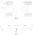
- FIG. 1 is a schematic structural diagram of a power consuming device according to a particular embodiment of the present application.
- the embodiment of the present application provides a battery B and a power consuming device using the battery B as a power source.
- the power consuming device using the battery B as the power source includes a vehicle A, a ship, a small aircraft, etc.
- the battery B is used to provide electric energy to the device, so as to generate a driving force for driving the device.
- the device may also use both electric energy and other types of energy (such as fossil energy) to jointly generate a driving force. Any device that may use the battery B as the power source falls within the scope of protection of the present application.
- the vehicle A in the embodiment of the present application may be a new energy vehicle which may be a battery electric vehicle, a hybrid electric vehicle or an extended range electric vehicle, etc.
- the battery B is arranged inside the vehicle A, and the battery B may be arranged at the bottom, head or tail of the vehicle A.
- the battery B may be configured for supplying power to the vehicle A.
- the battery B may be used as an operating power source for the vehicle A.
- the vehicle A may further include a controller C and a motor M, and the controller C is configured for controlling the battery B to supply power to the motor, for example, to meet a working power demand during start, navigation, and driving of the vehicle.
- the battery B may not only serve as an operating power source for the vehicle A, but also serve as a driving power source for the vehicle A, instead of or partially instead of fuel or natural gas, to provide driving power for the vehicle A.
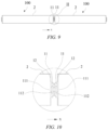
- FIG. 2 is a schematic structural diagram of the battery B according to some embodiments of the present application.
- the battery B of some embodiments of the present application includes at least two battery cells 100, and electrode terminals 11 of two of the battery cells 100 are welded together.
- the electrode terminals 11 of the battery cell 100 include a positive terminal and a negative terminal which are arranged on two ends of the battery cell 100 in a lengthwise direction X respectively.
- the positive terminals of the two battery cells 100 may be oppositely arranged and welded, so as to connect the two battery cells 100 in parallel; or the negative terminals of the two battery cells 100 are oppositely arranged and welded together, so as to connect the two battery cells 100 in parallel; and it is also possible that the positive terminal of one battery cell 100 and the negative terminal of the other battery cell 100 are oppositely arranged and welded together, so as to connect the two battery cells 100 in series.
- the battery B may include a plurality of battery cells 100.
- the electrode terminals 11 of the two battery cells 100 may be welded, and then the battery cells 100 welded in pairs are connected in parallel or in series or in series and parallel to form the battery B.
- the series-parallel connection means a combination of serial connection and parallel connection.
- the electrode terminals 11 of the two battery cells 100 may be welded together, and then one of electrode terminals 11 of the other battery cell 100 is welded to the electrode terminal 11 on an end of one battery cell 100 of the two battery cells 100 that have been welded together to form the battery B in which three battery cells 100 are welded along a straight line, or so on.
- the plurality of battery cells 100 are welded together along a straight line to form the battery B.
- FIG. 3 is a schematic structural diagram of a battery cell 100 according to some embodiments of the present application.
- the battery cell 100 includes an end cap assembly 1, a housing 2, an electrode assembly arranged in the housing 2, and an electrolyte filled into the battery cell 100 (the electrode assembly and the electrolyte are not shown in the figures below in the accompanying drawings of each embodiment in order to clearly show main invention points of the present application).
- the end cap assembly 1 is connected to the housing 2, and the electrode assembly is enclosed in the housing 2.
- the end cap assembly 1 includes an end cap 12 and an electrode terminal 11 arranged on the end cap 12, wherein the electrode assembly is electrically connected to the electrode terminal 11.
- the end cap 12 covers an opening of the housing 2, so as to provide an enclosed space for the electrode assembly and the electrolyte.
- the housing 2 may have various shapes such as a cylinder and a cuboid.
- the shape of the housing 2 may be determined depending on the specific shape of the electrode assembly. For example, if the electrode assembly is of a cylinder structure, the cylinder structure may be selected for the housing 2; and if the electrode assembly is of a cuboid structure, the cuboid structure may be selected for the housing 2. It may be understood that the housing 2 may have a different shape from the electrode assembly.
- the housing 2 is of a cylinder structure having two open ends, the two open ends are covered with the end cap assemblies 1 respectively, the end cap assemblies 1 on two sides each are provided with the electrode terminals 11, and the electrode terminals 11 on the two sides have opposite polarities.
- the housing 2 may be made of various materials, such as plastic, copper, iron, aluminum, stainless steel and an aluminum alloy, which is not specifically limited in the embodiment of the present application.
- the electrode assembly When the battery cell 100 is assembled, the electrode assembly is placed in the housing 2, then the electrode assembly is electrically connected and fixed to the electrode terminal 11, and the end caps 12 on two sides are fixedly connected to the housing 2, so as to complete the assembly of the battery cell 100. After the assembly is completed, the electrolyte is filled into the battery cell 100.
- the present application provides a battery.
- the battery includes at least two battery cells 100, wherein each of the battery cells 100 includes electrode terminals 11 arranged on end portions of two sides of the battery cell 100 in a lengthwise direction X, the electrode terminal 11 on one side of the battery cell 100 is provided with a filling port 111 for filling an electrolyte in the lengthwise direction X of the battery cell, and the electrode terminals 11 of the two battery cells 100 that have the filling ports 111 are oppositely arranged in the lengthwise direction X and are welded together, so as to seal the filling port 111.
- FIG. 4 is a top view of the battery cell 100 of FIG. 3 ; and FIG. 5 is a sectional view of the embodiment of FIG. 4 taken along line E-E.
- the electrode terminal 11 is arranged on the end cap 12, and the filling port 111 is provided in the electrode terminal 11.
- the filling port 111 is a through hole penetrating the electrode terminal 11, and after the battery cell 100 is assembled, the electrolyte is filled into the battery cell 100 through the filling port 111.
- the filling port 111 is provided in the electrode terminal 11, and the filling port 111 does not occupy a space of the end cap 12, such that the size of the electrode terminal 11 may be increased, thereby increasing the overcurrent area of the electrode terminal 11.
- FIG. 6 is a sectional view of the battery B according to an embodiment of the present application.
- electrode terminals 11 of the two battery cells 100 that have the filling ports 111 are oppositely arranged in the lengthwise direction X of the battery cells and are welded together to form the battery B.
- the electrode terminals 11 of the two battery cells 100 that have the filling ports 111 have the same polarity, and after the two electrode terminals 11 are oppositely arranged and welded together, the two battery cells 100 are connected in parallel to form the battery B.
- the polarities of the two oppositely arranged and welded electrode terminals 11 may also be configured to be opposite, in order to connect the two battery cells 100 in series to form the battery B.
- the filling ports 111 are provided in the electrode terminals 11, the two electrode terminals 11 having the filling ports 111 are oppositely arranged and welded together, the entire battery B is sealed directly by means of the electrode terminals 11, and no additional sealing procedure is needed, thereby improving the production efficiency and reducing the cost. Moreover, by welding the electrode terminals 11 of the two battery cells 100 that have the filling ports 111, no sealing pin is required for welding and sealing, so it is unnecessary to process a step structure to place the sealing pin 111, thereby reducing the work for machining the filling ports 111.
- the cross-sectional shape of the filling port 111 is not limited to a circular shape any more, and may be a variety of shapes suitable for a variety of situations, such as square, polygonal, and irregular, and the circular shape is not excluded.
- Various options are provided for a structural form of the filling port 111; and the machining requirements for the shape of the filling port are reduced, and it is not required to process a strictly circular filling port.
- FIG. 7 is an enlarged view of part I in FIG. 6 .
- the filling port 111 is located in the center of the electrode terminal 11 to facilitate communication between the filling ports 111 of the two battery cells 100.
- the provision of the filling ports 111 in the centers of the electrode terminals 11 allows the influence of the welding of the electrode terminals 11 on the filling ports 111 to be avoided, and facilitates the communication between two filling ports 111 when the two electrode terminals 11 abut against each other for supplement and balance of the electrolyte between the two battery cells 100.
- FIG. 8 is a sectional view of another embodiment of FIG. 4 taken along line E-E.
- the electrode terminal 11 of the battery cell 100 is arranged on the end cap 12, and the filling port 111 is provided in the electrode terminal 11.
- the filling port 111 is a through hole penetrating the electrode terminal 11.
- a groove 112 is further provided on a side surface of the electrode terminal 11 that has the filling port 111, and the groove 112 has a size greater than that of the filling port 111 in a direction perpendicular to the lengthwise direction X of the battery cell.
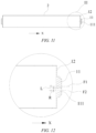
- FIG. 9 is a sectional view of the battery B according to another embodiment of the present application.
- FIG. 10 is an enlarged view of part II in FIG. 9 .
- the electrode terminals 11 of the two battery cells 100 that have the filling ports 111 are oppositely arranged in the lengthwise direction X of the battery cells and are welded together to form the battery B.
- the battery cells 100 are required to be horizontally placed. Since the filling ports 111 have not been sealed, the electrolyte in the battery cells 100 has the risk of flowing out through the filling ports 111 when the battery cells 100 are horizontally placed.
- a groove 112 is provided on an inner side surface of each of the filling ports 111, and after the battery cells 100 are horizontally placed, the electrolyte is first accumulated in the grooves 112 when flowing out of the battery cells 100.
- the two electrode terminals 11 having the filling ports 111 are welded together, thanks to the buffer storage of the electrolyte in the groove 112, the risk of the electrolyte flowing out through the filling ports 111 is reduced during welding, and the influence of the flowed-out electrolyte on the quality of a weld joint is avoided.
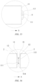
- FIG. 11 is a sectional view of yet another embodiment of FIG. 4 taken along line E-E;
- FIG. 12 is an enlarged view of part III of an embodiment of FIG. 11 .
- the filling ports 111 are provided offset from the centers of electrode terminals 11, so as to arrange the filling ports 111 of two battery cells 100 in a staggered manner.
- a center line F2 of the filling port 111 is offset from a center line F1 of the electrode terminal 11 by a distance L.
- the distance L is greater than a maximum distance R between an inner surface of the filling port 111 and the center line F2 of the filling port 111.
- FIG. 13 is a sectional view of the battery B according to yet another embodiment of the present application, and FIG. 14 is an enlarged view of part IV of an embodiment of FIG. 13 .
- the electrode terminals 11 of the two battery cells 100 that have the filling ports 111 are oppositely arranged in the lengthwise direction X of the battery cells and are welded together to form the battery B.
- the two filling ports 111 are arranged in a staggered manner, that is, the two filling ports 111 are not located on the same straight line in the lengthwise direction X of the battery cells.
- the filling ports 111 of the two battery cells 100 are arranged in a staggered manner, since the distance L by which the center line F2 of the filling ports 111 is offset from the center line F 1 of the electrode terminals 11 is greater than the maximum distance R of the filling ports 111, in this case, when the two filling ports 111 are arranged in a staggered manner, the two filling ports 111 may be completely staggered without communication therebetween, and after the two electrode terminals 11 are welded together, one filling port 111 may be blocked by a portion of the other electrode terminal 11 that has no filling port 111, such that the electrolyte in the two battery cells 100 is prevented from circulating between the battery cells during use.
- the filling ports 111 of the two battery cells 100 shown in FIG. 14 are staggered at an angle of 180 degrees, that is, the center lines of the two filling ports 111 and the center lines of the electrode terminals 11 are located in the same plane.
- the present application is not limited to a staggering angle of 180 degrees, and when the two electrode terminals 11 are oppositely arranged, it is only needed to ensure that two filling ports 111 are completely stagger without communication, such that the electrolyte in the two battery cells 100 may not circulate between the battery cells.
- the filling ports 111 are designed not to communicate with each other.
- FIG. 15 is an enlarged view of part III of another embodiment of FIG. 11 .
- the electrode terminal 11 is provided with a step portion 113 along the periphery of an end portion of the battery cell in the lengthwise direction X.
- the step portion 113 is annularly arranged along the end portion of the electrode terminal 11 to from a partial notch at the periphery of the end portion of the electrode terminal 11.
- the step portion 113 in FIG. 15 is an annularly-arranged beveled chamfer, and the cross-sectional shape of the step portion 113 may be another shape capable of forming a notch, such as a square shape, a trapezoid shape, and a circular arc shape.
- FIG. 16 is a partial enlarged sectional view of the welded connection of two battery cells 100 of FIG. 15 .
- the two electrode terminals 11 are welded at the welding groove 114, and during welding, reflections of welding laser are concentrated in the welding groove 114, thereby improving the welding quality, reducing the influences of laser welding on the end cap of the battery, enhancing the sealing performance of the battery B, and improving the yield of finished battery products.
- the filling port 111 has a circular, square, triangular, or polygonal cross section.
- a conventional filling port 111 is sealed by means of a sealing pin, laser welding is needed, and due to the path limitation of laser welding, the filling port 111 may only be made into a circular shape.
- the filling ports 111 are provided in the electrode terminals 11, the electrode terminals 11 of the two battery cells 100 are welded together, and no additional sealing pin is required for welding and sealing the filling ports 111.
- the filling ports 111 may be made into other shapes such as square shape, triangle shape and polygonal shape, is not limited by the path of laser welding, and is not limited to a circular shape, such that the filling ports 111 may be shaped more flexibly.
- FIG. 17 is a sectional view of the battery B according to another embodiment of the present application.
- Electrode terminals 11 of two of the battery cells 100 that have filling ports 111 are oppositely arranged and welded together to connect the two battery cells 100 in parallel, and the electrode terminals 11 of the two battery cells 100 are welded in the same manner as the embodiment shown in FIG. 7 .
- the filling port 111 may have the same structural form as that of FIGS. 10 or 14 , or have a combination of different structural forms.
- FIG. 18 is an enlarged view of part V in FIG. 17 .
- the electrode terminal of the other battery cell 100 that has the filling port 111 is welded to the electrode terminal 11 having no filling port 111 at an end portion of one battery cell 100 of the two battery cells 100 which are welded, and the polarity of the electrode terminal 11 having no filling port 111 is opposite that of the electrode terminal 11 having the filling port, so as to connect the two battery cells 100 in series.
- the electrode terminal 11 having no filling port 111 is of a solid structure, which may seal the filling port 111 of the electrode terminal 11 welded to the electrode terminal.
- the present application is not limited to welded connection of two battery cells 100 or welded connection of three battery cells 100 to form the battery B in the above embodiments, and a plurality of battery cells 100 may be welded as one piece in the above connection manner to form the battery B including the plurality of battery cells 100.
- the battery cells 100 may be cylindrical battery cells and/or the electrode terminals may be cylindrical electrode terminals.
- the present application is not limited thereto and may be adapted to other shapes of battery structures.
- the present application is not limited to the structure of the above embodiments, and may be a combination of the above embodiments.
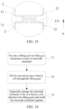
- FIG. 19 is a flow chart of a method for manufacturing a battery according to an embodiment of the present application.
- the present application further relates to a method for manufacturing a battery.
- the battery B includes at least two battery cells 100, wherein each of the battery cells 100 includes electrode terminals 11 arranged at end portions of two sides of the battery cell in the lengthwise direction X.
- the method for manufacturing a battery includes the following steps.
- a filling port 111 for filling an electrolyte is provided in the electrode terminal 11 on one side of the battery cell 100 in the lengthwise direction X of the battery cell.
- step S2 the electrolyte is filled into the battery cell 100 through the filling port 111.
- the electrode terminals 11 of the two battery cells 100 that have the filling ports 111 are oppositely arranged in the lengthwise direction X of the battery cells and are welded together.
- the filling port 111 is provided in the electrode terminal 11, and the filling port 111 does not occupy a space of the end cap 12, such that the size of the electrode terminal 11 may be increased, thereby increasing the overcurrent area of the electrode terminal 11.
- the two electrode terminals 11 having the filling ports 111 are oppositely arranged and welded together.
- the entire battery B is sealed directly by means of the electrode terminals 11 without an additional sealing procedure, thereby reducing the cost and improving the production efficiency.
- the method for manufacturing a battery further includes the step of testing the battery for gas tightness. After the battery cell 100 is assembled, the electrolyte is filled and sealing is completed, a gas tightness test is required to ensure the sealing performance of the battery cell 100 and ensure the yield of the battery cell 100.
- the battery cell 100 is not additionally sealed, and the electrode terminals 11 of the battery cells 100 that have the filling ports 111 are oppositely arranged and welded together to form the battery B, thereby sealing the entire battery B. Therefore, a gas tightness test is required for the entire battery B.
- the method further includes the step of filling helium into the battery cells 100 through the filling ports 111.
- two electrode terminals 11 having the filling ports 111 are welded together to seal the entire battery B. After the welding is completed, the entire battery B is subjected to the gas tightness test to detect helium leakage from the battery B, and if no helium leakage, it is indicated that the entire battery B is well sealed.
- helium is filled into the battery cells 100 through the filling ports 111, then the electrode terminals 11 of the two battery cells 100 are welded together, and it is unnecessary to additionally provide a gas tightness test hole and seal the test hole, thereby reducing battery manufacturing procedures and improving the production efficiency.
- the present application relates to a power consuming device using the battery B as described above or as manufactured by the above method for manufacturing a battery.
Landscapes
- Chemical & Material Sciences (AREA)
- Chemical Kinetics & Catalysis (AREA)
- Electrochemistry (AREA)
- General Chemical & Material Sciences (AREA)
- Engineering & Computer Science (AREA)
- Manufacturing & Machinery (AREA)
- Aviation & Aerospace Engineering (AREA)
- Materials Engineering (AREA)
- Connection Of Batteries Or Terminals (AREA)
- Filling, Topping-Up Batteries (AREA)
- Sealing Battery Cases Or Jackets (AREA)
Abstract
Description
- The present application relates to the technical field of energy storage devices, and in particular to a battery, a method for manufacturing a battery, and a power consuming device.
- Energy conservation and emission reduction are the key to the sustainable development of the automobile industry. In this case, electric vehicles have become an important part of the sustainable development of the automotive industry due to their advantages in energy conservation and environmental protection. For the electric vehicles, battery technology is an important factor in their development.
- In a battery production process, it is necessary to fill an electrolyte into the battery cell. In the prior art, a filling port is provided in an end cap of the battery cell, and it is necessary to seal the filling port after the electrolyte is filled through the filling port, resulting in a complex process and high cost.
- In order to solve the above problem, the present application provides a battery. A filling port of the battery does not occupy a space of an end cap, such that sufficient and flexible arrangements and arrangement spaces may be provided for other elements on the end cap with no influence the structural strength of the end cap, and no additional sealing procedure is required for the filling port, such that the production efficiency is high, and the cost is low.
- A first aspect of an embodiment of the present application provides a battery. The battery includes at least two battery cells, wherein each of the battery cell includes electrode terminals arranged at end portions of two sides of the battery cell in a lengthwise direction, wherein a filling port for filling an electrolyte is provided in the electrode terminal on one side in the lengthwise direction of the battery cell, and the electrode terminals of the two battery cells are oppositely arranged in the lengthwise direction of the battery cells and are welded together to seal the filling ports.
- The filling port is provided on the electrode terminal and does not occupy a space of an end cap, such that the arrangement of other elements may be facilitated. For example, the size of the electrode terminal may be increased, thereby increasing the overcurrent area of the electrode terminal. The two electrode terminals having the filling ports are oppositely arranged and welded together, the entire battery is sealed directly by means of the electrode terminals without an additional sealing procedure, thereby improving the production efficiency and reducing the cost.
- In some embodiments, the filling ports are located in the centers of the electrode terminals, so as to facilitate communication between the filling ports of the two battery cells.
- The provision of the filling ports in the centers of the electrode terminals allows the influence of the welding of the electrode terminals on the filling ports to be avoided, and facilitates the communication between two filling ports when the two electrode terminals abut against each other for supplement and balance of the electrolyte between the two battery cells.
- In some embodiments, a groove is further provided on a side surface of the electrode terminal that has the filling port, and the size of the groove is greater than that of the filling port in a direction perpendicular to the lengthwise direction of the battery cell.
- When the two electrode terminals having the filling ports are welded together, thanks to the buffer storage of the electrolyte in the groove, the risk of the electrolyte flowing out through the filling ports is reduced during welding, and the influence of the flowed-out electrolyte on the quality of a weld joint is avoided.
- In some embodiments, the filling ports is offset from the centers of the electrode terminals, so as to stagger the filling ports of the two battery cells.
- When the two filling ports are arranged in a staggered manner, the two filling ports may be completely staggered without communication therebetween, and after the two electrode terminals are welded together, one filling port may be blocked by a portion of the other electrode terminal that has no filling port, such that the electrolyte in the two battery cells is prevented from circulating between the battery cells during use.
- In some embodiments, a step portion is provided at the periphery of an end portion of the electrode terminal in the lengthwise direction of the battery cell, and the step portions of the two battery cells are oppositely arranged to form a welding groove.
- The two electrode terminals are welded at the welding groove, and during welding, reflections of welding laser are concentrated in the welding groove, thereby improving the welding quality and enhancing the sealing performance of the battery.
- In some embodiments, the filling port has a circular, square, triangular or polygonal cross section. The electrode terminals of the two battery cells are welded together, and no additional sealing pin is required for welding and sealing the filling ports. Therefore, the shapes of the filling ports are not limited by the path of laser welding, are not limited to a circular shape, such that the filling ports may be shaped more flexibly.
- In some embodiments, the battery cells are cylindrical battery cells, and/or the electrode terminals are cylindrical electrode terminals.
- A second aspect of an embodiment of the present application provides a method for manufacturing a battery. The battery includes at least two battery cells, wherein each of the battery cell includes electrode terminals arranged at end portions of two sides of the battery cell in a lengthwise direction. The method includes: providing a filling port for filling an electrolyte in the electrode terminal on one side in the lengthwise direction of the battery cell; filling the electrolyte into the battery cell through the filling port; and oppositely arranging the electrode terminals of the two battery cells that have the filling ports in the lengthwise direction of the battery cells and welding the electrode terminals together.
- In some embodiments, the method for manufacturing a battery further includes the step of testing the battery for gas tightness in order to ensure that the battery has a good gas tightness.
- In some embodiments, the method further includes, prior to the oppositely arranged the electrode terminals of the two battery cells that have the filling ports in the lengthwise direction of the battery cells and welding the electrode terminals together, the step of filling helium into the battery cells through the filling ports.
- Helium is filled into the battery cells through the filling ports, then the electrode terminals of the two battery cells are welded together, and it is unnecessary to additionally provide an air tightness test hole and seal the test hole, thereby reducing battery manufacturing procedures and improving the production efficiency.
- A third aspect of an embodiment of the present application provides a power consuming device, including the battery of the first aspect, or a battery manufactured by the method for manufacturing a battery of the second aspect, the battery being configured for providing electric energy.
- It should be understood that the above general descriptions and the detailed description hereinafter are merely exemplary, and cannot limit the present application.
- To more clearly describe technical solutions of embodiments of the present application, the drawings to be used in the embodiments of the present application will be described briefly below. Obviously, the drawings in the following description are merely specific embodiments of the present application. For those skilled in the art, other embodiments may also be obtained according to the following drawings without any creative effort.
-
FIG. 1 is a schematic structural diagram of a power consuming device according to a particular embodiment of the present application; -
FIG. 2 is a schematic structural diagram of a battery according to some embodiments of the present application; -
FIG. 3 is a schematic structural diagram of a battery cell according to some embodiments of the present application; -
FIG. 4 is a top view of the battery cell ofFIG. 3 ; -
FIG. 5 is a sectional view of the embodiment ofFIG. 4 taken along line E-E; -
FIG. 6 is a sectional view of a battery according to an embodiment of the present application; -
FIG. 7 is an enlarged view of part I inFIG. 6 ; -
FIG. 8 is a sectional view of another embodiment ofFIG. 4 taken along line E-E; -
FIG. 9 is a sectional view of a battery according to another embodiment of the present application; -
FIG. 10 is an enlarged view of part II inFIG. 9 ; -
FIG. 11 is a sectional view of yet another embodiment ofFIG. 4 taken along line E-E; -
FIG. 12 is an enlarged view of part III of an embodiment ofFIG. 11 ; -
FIG. 13 is a top view of a battery according to yet another embodiment of the present application; -
FIG. 14 is an enlarged view of part IV of an embodiment ofFIG. 13 ; -
FIG. 15 is an enlarged view of a portion III of another embodiment ofFIG. 11 ; -
FIG. 16 is a partial enlarged sectional view of the welded connection of two battery cells ofFIG. 15 ; -
FIG. 17 is a sectional view of a battery according to still yet another embodiment of the present application; -
FIG. 18 is an enlarged view of part V inFIG. 17 ; and -
FIG. 19 is a flow chart of a method for manufacturing a battery according to an embodiment of the present application. -
- A - vehicle;
- B - battery;
- C - controller;
- M - motor;
- 100-battery cell;
- 1 - end cap assembly;
- 11 - electrode terminal;
- 111 - filling port;
- 112 - groove;
- 113 - step portion;
- 114 - welding groove;
- 12 - end cap;
- 11 - electrode terminal;
- 2 - housing.
- The accompanying drawings herein are incorporated into the description and form a part of the description, illustrate the embodiments conforming to the present application, and are intended to explain principles of the present application together with the description.
- To better understand the technical solutions of the present application, embodiments of the present application will be described in detail below with reference to the accompanying drawings.
- It should be clear that the embodiments described are merely some of, rather than all of, the embodiments of the present application. All other embodiments obtained by those of ordinary skill in the art based on the embodiments of the present application without any creative effort shall fall within the scope of protection of the present application.
- The terms used in the embodiments of the present application are merely for the purpose of describing specific embodiments, but are not intended to limit the present application. The terms "a/an", "the" and "this" of singular forms used in the embodiments and the appended claims of the present application are also intended to include plural forms, unless otherwise specified in the context clearly.
- It should be understood that the term "and/or" used herein is merely intended to describe an associated relation of associated objects, representing that three relations may exist, for example, A and/or B, may include: the three instances of A alone, A and B simultaneously, and B alone. In addition, the character "/" herein generally indicates an "or" relation between the associated objects.
- It should be noted that the directional terms such as "above", "under", "left", and "right" described in the embodiments of the present application are described as seen from the angles shown in the accompanying drawings, and should not be understood as limitations to the embodiments of the present application. In addition, in the context, it should be further understood that when an element is referred to as being "above" or "under" another element, the element can not only be directly connected "above" or "under" another element, but also be indirectly connected "above" or "under" another element by means of an intermediate element.
- A battery mentioned in an embodiment of the present application refers to a single physical module including one or more battery cells to provide higher voltage and capacity.
- A battery cell includes an electrode assembly, a housing, an end cap assembly, and an electrolyte filled into the battery cell. The electrode assembly is arranged in the housing, and the end cap assembly is connected to the housing to enclose the electrode assembly in the housing. The end cap assembly includes an end cap and an electrode terminal arranged on the end cap, wherein the electrode assembly is electrically connected to the electrode terminal. A plurality of battery cells may be connected in series or in parallel or in series and parallel by means of the electrode terminals, and the series-parallel connection means a combination of serial connection and parallel connection.
- The applicant has noted that a filling port for filling an electrolyte into the battery cell is usually arranged on the end cap, and since the filling port occupies a space of the end cap, the electrode terminal arranged on the end cap may not be made bigger, and overcurrent area of the electrode terminal is reduced accordingly. The filling port is provided in the end cap, which results in a reduction in the structural strength of the end cap, and an additional sealing procedure is required for the filling port.
- In order to solve the above problem, a structure of a battery is improved, in which the filling port is provided in the electrode terminal such that the filling port does not occupy the space of the end cap and the electrode terminal may be made bigger, which increases the overcurrent area and has no influence on the structural strength of the end cap. Electrode terminals of two battery cells that have filling ports are oppositely arranged and welded together such that no additional sealing procedure is required for the filling ports, thereby improving the production efficiency and reducing the cost. The embodiments of the present application will be further described below.
-
FIG. 1 is a schematic structural diagram of a power consuming device according to a particular embodiment of the present application. - As shown in
FIG. 1 , the embodiment of the present application provides a battery B and a power consuming device using the battery B as a power source. The power consuming device using the battery B as the power source includes a vehicle A, a ship, a small aircraft, etc. The battery B is used to provide electric energy to the device, so as to generate a driving force for driving the device. The device may also use both electric energy and other types of energy (such as fossil energy) to jointly generate a driving force. Any device that may use the battery B as the power source falls within the scope of protection of the present application. - As shown in
FIG. 1 , with the vehicle A as an example of the power consuming device, the vehicle A in the embodiment of the present application may be a new energy vehicle which may be a battery electric vehicle, a hybrid electric vehicle or an extended range electric vehicle, etc. The battery B is arranged inside the vehicle A, and the battery B may be arranged at the bottom, head or tail of the vehicle A. The battery B may be configured for supplying power to the vehicle A. For example, the battery B may be used as an operating power source for the vehicle A. The vehicle A may further include a controller C and a motor M, and the controller C is configured for controlling the battery B to supply power to the motor, for example, to meet a working power demand during start, navigation, and driving of the vehicle. - In some embodiments of the present application, the battery B may not only serve as an operating power source for the vehicle A, but also serve as a driving power source for the vehicle A, instead of or partially instead of fuel or natural gas, to provide driving power for the vehicle A.
-
FIG. 2 is a schematic structural diagram of the battery B according to some embodiments of the present application. - As shown in
FIG. 2 , the battery B of some embodiments of the present application includes at least twobattery cells 100, andelectrode terminals 11 of two of thebattery cells 100 are welded together. Theelectrode terminals 11 of thebattery cell 100 include a positive terminal and a negative terminal which are arranged on two ends of thebattery cell 100 in a lengthwise direction X respectively. - When the two
battery cells 100 are welded together to form the battery B, the positive terminals of the twobattery cells 100 may be oppositely arranged and welded, so as to connect the twobattery cells 100 in parallel; or the negative terminals of the twobattery cells 100 are oppositely arranged and welded together, so as to connect the twobattery cells 100 in parallel; and it is also possible that the positive terminal of onebattery cell 100 and the negative terminal of theother battery cell 100 are oppositely arranged and welded together, so as to connect the twobattery cells 100 in series. - In some embodiments, in order to satisfy different power demands, the battery B may include a plurality of
battery cells 100. Optionally, theelectrode terminals 11 of the twobattery cells 100 may be welded, and then thebattery cells 100 welded in pairs are connected in parallel or in series or in series and parallel to form the battery B. The series-parallel connection means a combination of serial connection and parallel connection. Alternatively, theelectrode terminals 11 of the twobattery cells 100 may be welded together, and then one ofelectrode terminals 11 of theother battery cell 100 is welded to theelectrode terminal 11 on an end of onebattery cell 100 of the twobattery cells 100 that have been welded together to form the battery B in which threebattery cells 100 are welded along a straight line, or so on. The plurality ofbattery cells 100 are welded together along a straight line to form the battery B. -
FIG. 3 is a schematic structural diagram of abattery cell 100 according to some embodiments of the present application. - As shown in
FIG. 3 , thebattery cell 100 includes anend cap assembly 1, ahousing 2, an electrode assembly arranged in thehousing 2, and an electrolyte filled into the battery cell 100 (the electrode assembly and the electrolyte are not shown in the figures below in the accompanying drawings of each embodiment in order to clearly show main invention points of the present application). Theend cap assembly 1 is connected to thehousing 2, and the electrode assembly is enclosed in thehousing 2. Theend cap assembly 1 includes anend cap 12 and anelectrode terminal 11 arranged on theend cap 12, wherein the electrode assembly is electrically connected to theelectrode terminal 11. Theend cap 12 covers an opening of thehousing 2, so as to provide an enclosed space for the electrode assembly and the electrolyte. Thehousing 2 may have various shapes such as a cylinder and a cuboid. The shape of thehousing 2 may be determined depending on the specific shape of the electrode assembly. For example, if the electrode assembly is of a cylinder structure, the cylinder structure may be selected for thehousing 2; and if the electrode assembly is of a cuboid structure, the cuboid structure may be selected for thehousing 2. It may be understood that thehousing 2 may have a different shape from the electrode assembly. - As an example, in
FIG. 3 , thehousing 2 is of a cylinder structure having two open ends, the two open ends are covered with theend cap assemblies 1 respectively, theend cap assemblies 1 on two sides each are provided with theelectrode terminals 11, and theelectrode terminals 11 on the two sides have opposite polarities. Thehousing 2 may be made of various materials, such as plastic, copper, iron, aluminum, stainless steel and an aluminum alloy, which is not specifically limited in the embodiment of the present application. - When the
battery cell 100 is assembled, the electrode assembly is placed in thehousing 2, then the electrode assembly is electrically connected and fixed to theelectrode terminal 11, and the end caps 12 on two sides are fixedly connected to thehousing 2, so as to complete the assembly of thebattery cell 100. After the assembly is completed, the electrolyte is filled into thebattery cell 100. - In a particular embodiment, the present application provides a battery. The battery includes at least two
battery cells 100, wherein each of thebattery cells 100 includeselectrode terminals 11 arranged on end portions of two sides of thebattery cell 100 in a lengthwise direction X, theelectrode terminal 11 on one side of thebattery cell 100 is provided with a fillingport 111 for filling an electrolyte in the lengthwise direction X of the battery cell, and theelectrode terminals 11 of the twobattery cells 100 that have the fillingports 111 are oppositely arranged in the lengthwise direction X and are welded together, so as to seal the fillingport 111. -
FIG. 4 is a top view of thebattery cell 100 ofFIG. 3 ; andFIG. 5 is a sectional view of the embodiment ofFIG. 4 taken along line E-E. - As shown in
FIGS. 4 and5 , theelectrode terminal 11 is arranged on theend cap 12, and the fillingport 111 is provided in theelectrode terminal 11. The fillingport 111 is a through hole penetrating theelectrode terminal 11, and after thebattery cell 100 is assembled, the electrolyte is filled into thebattery cell 100 through the fillingport 111. - The filling
port 111 is provided in theelectrode terminal 11, and the fillingport 111 does not occupy a space of theend cap 12, such that the size of theelectrode terminal 11 may be increased, thereby increasing the overcurrent area of theelectrode terminal 11. -
FIG. 6 is a sectional view of the battery B according to an embodiment of the present application. - As shown in
FIG. 6 , after a certain amount of electrolyte is filled intobattery cells 100 through fillingports 111,electrode terminals 11 of the twobattery cells 100 that have the fillingports 111 are oppositely arranged in the lengthwise direction X of the battery cells and are welded together to form the battery B. - In this embodiment, the
electrode terminals 11 of the twobattery cells 100 that have the fillingports 111 have the same polarity, and after the twoelectrode terminals 11 are oppositely arranged and welded together, the twobattery cells 100 are connected in parallel to form the battery B. The polarities of the two oppositely arranged and weldedelectrode terminals 11 may also be configured to be opposite, in order to connect the twobattery cells 100 in series to form the battery B. - After the filling of electrolyte into the
battery cell 100 is completed through the fillingport 111, it is necessary to seal the fillingport 111 to ensure the overall sealing performance of thebattery cell 100. In the prior art, in order to seal the fillingport 111, after an electrolyte filling procedure is completed, it is necessary to mount a sealing pin in the fillingport 111, and the sealing pin is welded in the fillingport 111 by means of laser welding to seal the fillingport 111. Before the sealing pin is welded, in order to prevent the sealing pin placed in the fillingport 111 from falling into thebattery cell 100, a step structure is required to be provided inside the fillingport 111 to position the sealing pin. Sealing the fillingport 111 by means of the sealing pin complicates the machining of the fillingport 111 and additionally provides a procedure of fixing the sealing pin. - In the embodiment of the present application, the filling
ports 111 are provided in theelectrode terminals 11, the twoelectrode terminals 11 having the fillingports 111 are oppositely arranged and welded together, the entire battery B is sealed directly by means of theelectrode terminals 11, and no additional sealing procedure is needed, thereby improving the production efficiency and reducing the cost. Moreover, by welding theelectrode terminals 11 of the twobattery cells 100 that have the fillingports 111, no sealing pin is required for welding and sealing, so it is unnecessary to process a step structure to place the sealingpin 111, thereby reducing the work for machining the fillingports 111. Moreover, since the procedure for laser welding of the sealing pin is eliminated, the cross-sectional shape of the fillingport 111 is not limited to a circular shape any more, and may be a variety of shapes suitable for a variety of situations, such as square, polygonal, and irregular, and the circular shape is not excluded. Various options are provided for a structural form of the fillingport 111; and the machining requirements for the shape of the filling port are reduced, and it is not required to process a strictly circular filling port. -
FIG. 7 is an enlarged view of part I inFIG. 6 . - As shown in
FIG. 7 , in some embodiments, the fillingport 111 is located in the center of theelectrode terminal 11 to facilitate communication between the fillingports 111 of the twobattery cells 100. - The provision of the filling
ports 111 in the centers of theelectrode terminals 11 allows the influence of the welding of theelectrode terminals 11 on the fillingports 111 to be avoided, and facilitates the communication between two fillingports 111 when the twoelectrode terminals 11 abut against each other for supplement and balance of the electrolyte between the twobattery cells 100. -
FIG. 8 is a sectional view of another embodiment ofFIG. 4 taken along line E-E. - As shown in
FIG. 8 , in another embodiment, theelectrode terminal 11 of thebattery cell 100 is arranged on theend cap 12, and the fillingport 111 is provided in theelectrode terminal 11. The fillingport 111 is a through hole penetrating theelectrode terminal 11. Agroove 112 is further provided on a side surface of theelectrode terminal 11 that has the fillingport 111, and thegroove 112 has a size greater than that of the fillingport 111 in a direction perpendicular to the lengthwise direction X of the battery cell. -
FIG. 9 is a sectional view of the battery B according to another embodiment of the present application; andFIG. 10 is an enlarged view of part II inFIG. 9 . - As shown in
FIGS. 9 and 10 , after a certain amount of electrolyte is filled into thebattery cells 100 through the fillingports 111, theelectrode terminals 11 of the twobattery cells 100 that have the fillingports 111 are oppositely arranged in the lengthwise direction X of the battery cells and are welded together to form the battery B. - When the
electrode terminals 11 of the twobattery cells 100 are welded together, thebattery cells 100 are required to be horizontally placed. Since the fillingports 111 have not been sealed, the electrolyte in thebattery cells 100 has the risk of flowing out through the fillingports 111 when thebattery cells 100 are horizontally placed. - As shown in
FIG. 10 , agroove 112 is provided on an inner side surface of each of the fillingports 111, and after thebattery cells 100 are horizontally placed, the electrolyte is first accumulated in thegrooves 112 when flowing out of thebattery cells 100. When the twoelectrode terminals 11 having the fillingports 111 are welded together, thanks to the buffer storage of the electrolyte in thegroove 112, the risk of the electrolyte flowing out through the fillingports 111 is reduced during welding, and the influence of the flowed-out electrolyte on the quality of a weld joint is avoided. -
FIG. 11 is a sectional view of yet another embodiment ofFIG. 4 taken along line E-E;FIG. 12 is an enlarged view of part III of an embodiment ofFIG. 11 . - As shown in
FIGS. 11 and 12 , in further embodiments, the fillingports 111 are provided offset from the centers ofelectrode terminals 11, so as to arrange the fillingports 111 of twobattery cells 100 in a staggered manner. - As shown in
FIG. 12 , a center line F2 of the fillingport 111 is offset from a center line F1 of theelectrode terminal 11 by a distance L. In a particular embodiment, the distance L is greater than a maximum distance R between an inner surface of the fillingport 111 and the center line F2 of the fillingport 111. -
FIG. 13 is a sectional view of the battery B according to yet another embodiment of the present application, andFIG. 14 is an enlarged view of part IV of an embodiment ofFIG. 13 . - As shown in
FIGS. 13 and 14 , in this embodiment, after a certain amount of electrolyte is filled into thebattery cells 100 through the fillingports 111, theelectrode terminals 11 of the twobattery cells 100 that have the fillingports 111 are oppositely arranged in the lengthwise direction X of the battery cells and are welded together to form the battery B. When the twoelectrode terminals 11 are oppositely arranged, the two fillingports 111 are arranged in a staggered manner, that is, the two fillingports 111 are not located on the same straight line in the lengthwise direction X of the battery cells. - As shown in
FIG. 14 , the fillingports 111 of the twobattery cells 100 are arranged in a staggered manner, since the distance L by which the center line F2 of the fillingports 111 is offset from thecenter line F 1 of theelectrode terminals 11 is greater than the maximum distance R of the fillingports 111, in this case, when the two fillingports 111 are arranged in a staggered manner, the two fillingports 111 may be completely staggered without communication therebetween, and after the twoelectrode terminals 11 are welded together, one fillingport 111 may be blocked by a portion of theother electrode terminal 11 that has no fillingport 111, such that the electrolyte in the twobattery cells 100 is prevented from circulating between the battery cells during use. - The filling
ports 111 of the twobattery cells 100 shown inFIG. 14 are staggered at an angle of 180 degrees, that is, the center lines of the two fillingports 111 and the center lines of theelectrode terminals 11 are located in the same plane. The present application is not limited to a staggering angle of 180 degrees, and when the twoelectrode terminals 11 are oppositely arranged, it is only needed to ensure that two fillingports 111 are completely stagger without communication, such that the electrolyte in the twobattery cells 100 may not circulate between the battery cells. When the twoelectrode terminals 11 abutting against each other are two electrodes having opposite polarities, it is advantageous if the fillingports 111 are designed not to communicate with each other. -
FIG. 15 is an enlarged view of part III of another embodiment ofFIG. 11 . - As shown in
FIG. 15 , in another embodiment, theelectrode terminal 11 is provided with astep portion 113 along the periphery of an end portion of the battery cell in the lengthwise direction X. Thestep portion 113 is annularly arranged along the end portion of theelectrode terminal 11 to from a partial notch at the periphery of the end portion of theelectrode terminal 11. Thestep portion 113 inFIG. 15 is an annularly-arranged beveled chamfer, and the cross-sectional shape of thestep portion 113 may be another shape capable of forming a notch, such as a square shape, a trapezoid shape, and a circular arc shape. -
FIG. 16 is a partial enlarged sectional view of the welded connection of twobattery cells 100 ofFIG. 15 . - As shown in
FIG. 16 , whenelectrode terminals 11 of twobattery cells 100 of this embodiment are oppositely arranged and welded together, since partial notches are provided by thestep portions 113 on the end portions of theelectrode terminals 11, awelding groove 114 is formed after the twostep portions 113 are oppositely arranged and the two notches correspond to each other. - The two
electrode terminals 11 are welded at thewelding groove 114, and during welding, reflections of welding laser are concentrated in thewelding groove 114, thereby improving the welding quality, reducing the influences of laser welding on the end cap of the battery, enhancing the sealing performance of the battery B, and improving the yield of finished battery products. - In some embodiments, the filling
port 111 has a circular, square, triangular, or polygonal cross section. When aconventional filling port 111 is sealed by means of a sealing pin, laser welding is needed, and due to the path limitation of laser welding, the fillingport 111 may only be made into a circular shape. In the present application, the fillingports 111 are provided in theelectrode terminals 11, theelectrode terminals 11 of the twobattery cells 100 are welded together, and no additional sealing pin is required for welding and sealing the fillingports 111. Therefore, the fillingports 111 may be made into other shapes such as square shape, triangle shape and polygonal shape, is not limited by the path of laser welding, and is not limited to a circular shape, such that the fillingports 111 may be shaped more flexibly. - In the above various embodiments, while opposite arrangement and welded connection of two
battery cells 100 are described, a plurality ofbattery cells 100 may be welded as one piece. Welded connection of threebattery cells 100 will be described as an example in the embodiments below. -
FIG. 17 is a sectional view of the battery B according to another embodiment of the present application. - As shown in
FIG. 17 , threebattery cells 100 are welded as one piece to form the batteryB. Electrode terminals 11 of two of thebattery cells 100 that have fillingports 111 are oppositely arranged and welded together to connect the twobattery cells 100 in parallel, and theelectrode terminals 11 of the twobattery cells 100 are welded in the same manner as the embodiment shown inFIG. 7 . The fillingport 111 may have the same structural form as that ofFIGS. 10 or14 , or have a combination of different structural forms. -
FIG. 18 is an enlarged view of part V inFIG. 17 . - As shown in
FIG. 18 , the electrode terminal of theother battery cell 100 that has the fillingport 111 is welded to theelectrode terminal 11 having no fillingport 111 at an end portion of onebattery cell 100 of the twobattery cells 100 which are welded, and the polarity of theelectrode terminal 11 having no fillingport 111 is opposite that of theelectrode terminal 11 having the filling port, so as to connect the twobattery cells 100 in series. InFIG. 18 , theelectrode terminal 11 having no fillingport 111 is of a solid structure, which may seal the fillingport 111 of theelectrode terminal 11 welded to the electrode terminal. - The present application is not limited to welded connection of two
battery cells 100 or welded connection of threebattery cells 100 to form the battery B in the above embodiments, and a plurality ofbattery cells 100 may be welded as one piece in the above connection manner to form the battery B including the plurality ofbattery cells 100. - In the above embodiments of the present application, the
battery cells 100 may be cylindrical battery cells and/or the electrode terminals may be cylindrical electrode terminals. Of course, the present application is not limited thereto and may be adapted to other shapes of battery structures. - Moreover, the present application is not limited to the structure of the above embodiments, and may be a combination of the above embodiments.
-
FIG. 19 is a flow chart of a method for manufacturing a battery according to an embodiment of the present application. - The present application further relates to a method for manufacturing a battery. The battery B includes at least two
battery cells 100, wherein each of thebattery cells 100 includeselectrode terminals 11 arranged at end portions of two sides of the battery cell in the lengthwise direction X. - As shown in
FIG. 19 , the method for manufacturing a battery includes the following steps. - At
step S 1, a fillingport 111 for filling an electrolyte is provided in theelectrode terminal 11 on one side of thebattery cell 100 in the lengthwise direction X of the battery cell. - At step S2, the electrolyte is filled into the
battery cell 100 through the fillingport 111. - At step S3, the
electrode terminals 11 of the twobattery cells 100 that have the fillingports 111 are oppositely arranged in the lengthwise direction X of the battery cells and are welded together. - According to the method for manufacturing a battery of the present application, the filling
port 111 is provided in theelectrode terminal 11, and the fillingport 111 does not occupy a space of theend cap 12, such that the size of theelectrode terminal 11 may be increased, thereby increasing the overcurrent area of theelectrode terminal 11. The twoelectrode terminals 11 having the fillingports 111 are oppositely arranged and welded together. The entire battery B is sealed directly by means of theelectrode terminals 11 without an additional sealing procedure, thereby reducing the cost and improving the production efficiency. Moreover, by welding theelectrode terminals 11 of the twobattery cells 100 that have the fillingports 111, no sealing pin is required for welding and sealing, so it is unnecessary to process a step structure to place the sealingpin 111, thereby reducing the work for machining the filling ports. - In some embodiments, the method for manufacturing a battery further includes the step of testing the battery for gas tightness. After the
battery cell 100 is assembled, the electrolyte is filled and sealing is completed, a gas tightness test is required to ensure the sealing performance of thebattery cell 100 and ensure the yield of thebattery cell 100. - In the embodiments of the present application, after the
battery cells 100 are assembled and the electrolyte is filled, thebattery cell 100 is not additionally sealed, and theelectrode terminals 11 of thebattery cells 100 that have the fillingports 111 are oppositely arranged and welded together to form the battery B, thereby sealing the entire battery B. Therefore, a gas tightness test is required for the entire battery B. - In order to perform the gas tightness test on the battery B of the present application, before the
electrode terminals 11 of the twobattery cells 100 that have the fillingports 111 are oppositely arranged in the lengthwise direction X of the battery cells and are welded together, the method further includes the step of filling helium into thebattery cells 100 through the fillingports 111. - After helium is filled into the
battery cells 100, twoelectrode terminals 11 having the fillingports 111 are welded together to seal the entire battery B. After the welding is completed, the entire battery B is subjected to the gas tightness test to detect helium leakage from the battery B, and if no helium leakage, it is indicated that the entire battery B is well sealed. - According to the method for manufacturing a battery of the present application, helium is filled into the
battery cells 100 through the fillingports 111, then theelectrode terminals 11 of the twobattery cells 100 are welded together, and it is unnecessary to additionally provide a gas tightness test hole and seal the test hole, thereby reducing battery manufacturing procedures and improving the production efficiency. - The present application relates to a power consuming device using the battery B as described above or as manufactured by the above method for manufacturing a battery.
- The foregoing descriptions are merely preferred embodiments of the present application, but are not intended to limit the present application. For those skilled in the art, the present application may have various modifications and variations. Any modifications, equivalent substitutions, improvements, and the like made within the spirit and principle of the present application should be included within the scope of protection of the present application.
Claims (12)
- A battery, characterized by comprising at least two battery cells, whereineach of the battery cell comprises electrode terminals arranged at end portions of two sides of the battery cell in a lengthwise direction,whereina filling port for filling an electrolyte is provided in the electrode terminal on one side in the lengthwise direction of the battery cell, andthe electrode terminals of the two battery cells are oppositely arranged in the lengthwise direction of the battery cells and are welded together to seal the filling ports.
- The battery according to claim 1, characterized in that the electrode terminals of the two battery cells that have the filling ports are oppositely arranged in the lengthwise direction of the battery cells and are welded together.
- The battery according to claim 2, characterized in that the filling ports are located in the centers of the electrode terminals to communicate the filling portsof the two battery cells.
- The battery according to any one of claims 1-3, characterized in that a groove is further provided on a side surface of the electrode terminal that has the filling port, and the size of the groove is greater than that of the filling port in a direction perpendicular to the lengthwise direction of the battery cell.
- The battery according to any one of claims 1-3, characterized in that the filling ports are offset from the centers of the electrode terminals, so as to stagger the filling ports of the two battery cells.
- The batteryaccording to any one of claims 1-5, characterized in that a step portion is provided at the periphery of an end portion of the electrode terminal in the lengthwise direction of the battery cell, and the step portions of the two battery cells are oppositely arranged to form a welding groove.
- The battery according to any one of claims 1-6, characterized in that the filling port has a circular, square, triangular or polygonal cross section.
- The battery according to any one of claims 1-7, characterized in that the battery cells are cylindrical battery cells, and/or the electrode terminals are cylindrical electrode terminals.
- A method for manufacturing a battery, the battery comprising at least two battery cells, and each of the battery cells comprising electrode terminals arranged at end portions of two sides of the battery cell in a lengthwise direction, characterized in that the method comprises:providing a filling port for filling an electrolyte in the electrode terminal on one side in the lengthwise direction of the battery cell;filling the electrolyte into the battery cell through the filling port; andoppositely arranging the electrode terminals of the two battery cells that have the filling ports in the lengthwise direction of the battery cells and welding the electrode terminals together.
- The method for manufacturing a battery according to claim 9, characterized by further comprising the step of testing the battery for gas tightness.
- The method for manufacturing a battery according to claim 10, characterized by further comprising, prior to the oppositely arranged the electrode terminals of the two battery cells that have the filling ports in the lengthwise direction of the battery cellsand welding the electrode terminalstogether, the step of filling helium into the battery cells through the filling ports.
- A power consuming device, characterized by comprising the battery of any one of claims 1-8, or a battery manufactured by the method for manufacturing a battery of any one of claims 9-11, the battery being configured for providing electric energy.
Applications Claiming Priority (1)
| Application Number | Priority Date | Filing Date | Title |
|---|---|---|---|
| PCT/CN2021/112642 WO2023019374A1 (en) | 2021-08-14 | 2021-08-14 | Battery, battery manufacturing method and electric apparatus |
Publications (2)
| Publication Number | Publication Date |
|---|---|
| EP4199219A1 true EP4199219A1 (en) | 2023-06-21 |
| EP4199219A4 EP4199219A4 (en) | 2024-07-24 |
Family
ID=85239333
Family Applications (1)
| Application Number | Title | Priority Date | Filing Date |
|---|---|---|---|
| EP21953632.3A Pending EP4199219A4 (en) | 2021-08-14 | 2021-08-14 | BATTERY, BATTERY MANUFACTURING METHOD AND ELECTRICAL DEVICE |
Country Status (6)
| Country | Link |
|---|---|
| US (1) | US20230238674A1 (en) |
| EP (1) | EP4199219A4 (en) |
| JP (1) | JP7704847B2 (en) |
| KR (1) | KR102938785B1 (en) |
| CN (1) | CN116670879A (en) |
| WO (1) | WO2023019374A1 (en) |
Families Citing this family (1)
| Publication number | Priority date | Publication date | Assignee | Title |
|---|---|---|---|---|
| JP7741835B2 (en) * | 2023-03-06 | 2025-09-18 | プライムプラネットエナジー&ソリューションズ株式会社 | Sealed electricity storage device, its manufacturing method and disassembly method |
Family Cites Families (10)
| Publication number | Priority date | Publication date | Assignee | Title |
|---|---|---|---|---|
| JP3445171B2 (en) | 1998-11-04 | 2003-09-08 | 日本碍子株式会社 | Lithium secondary battery |
| JP2000200597A (en) * | 1999-01-05 | 2000-07-18 | Japan Storage Battery Co Ltd | Battery |
| DE10064648C2 (en) * | 1999-12-28 | 2003-09-18 | Honda Motor Co Ltd | battery unit |
| DE102006005532B4 (en) * | 2006-02-07 | 2009-09-24 | Epcos Ag | Connection element for an electric capacitor, capacitor and capacitor connection |
| JP6057129B2 (en) | 2013-03-21 | 2017-01-11 | トヨタ自動車株式会社 | Manufacturing method of sealed battery |
| CN204834764U (en) * | 2015-06-17 | 2015-12-02 | 深圳市沃特玛电池有限公司 | Cylindrical high magnification lithium ion battery of edge weld |
| CN208284552U (en) * | 2018-06-01 | 2018-12-25 | 苏州安靠电源有限公司 | The uniform end face weld battery of fluid injection |
| CN110518174B (en) * | 2019-10-23 | 2020-03-20 | 比亚迪股份有限公司 | Battery, battery module, battery pack and electric vehicle |
| CN112993473B (en) * | 2019-11-29 | 2023-09-05 | 比亚迪股份有限公司 | A battery, a battery module, a battery pack and an electric vehicle |
| CN112072017B (en) * | 2020-08-19 | 2025-03-28 | 江苏正力新能电池技术股份有限公司 | A battery module based on battery cell string |
-
2021
- 2021-08-14 JP JP2023519748A patent/JP7704847B2/en active Active
- 2021-08-14 KR KR1020237011272A patent/KR102938785B1/en active Active
- 2021-08-14 EP EP21953632.3A patent/EP4199219A4/en active Pending
- 2021-08-14 WO PCT/CN2021/112642 patent/WO2023019374A1/en not_active Ceased
- 2021-08-14 CN CN202180085491.2A patent/CN116670879A/en active Pending
-
2023
- 2023-03-10 US US18/120,239 patent/US20230238674A1/en active Pending
Also Published As
| Publication number | Publication date |
|---|---|
| JP7704847B2 (en) | 2025-07-08 |
| JP2023543473A (en) | 2023-10-16 |
| CN116670879A (en) | 2023-08-29 |
| WO2023019374A1 (en) | 2023-02-23 |
| EP4199219A4 (en) | 2024-07-24 |
| KR102938785B1 (en) | 2026-03-12 |
| US20230238674A1 (en) | 2023-07-27 |
| KR20230061487A (en) | 2023-05-08 |
Similar Documents
| Publication | Publication Date | Title |
|---|---|---|
| US20240154218A1 (en) | Battery cell, battery, and electrical apparatus | |
| EP2378593B1 (en) | Battery module | |
| US20220384916A1 (en) | Battery cell, battery, electrical device, and battery cell manufacturing method and device | |
| US12266806B2 (en) | Battery cell, battery, electrical device, and manufacturing method and device for battery cell | |
| KR102889975B1 (en) | Battery cells, batteries, electrical devices, methods for manufacturing battery cells and devices | |
| KR102804305B1 (en) | Battery cell and its manufacturing method and manufacturing system, battery and electric device | |
| CN214411277U (en) | Cylindrical battery monomer, battery and power consumption device | |
| US20250096381A1 (en) | Battery cell, battery and electrical apparatus | |
| US20230155262A1 (en) | Housing, battery cell, battery and electric apparatus | |
| KR20220151694A (en) | End cover assembly, battery cell, method and equipment for manufacturing battery and battery cell | |
| JP7488909B2 (en) | Battery cell, battery, electrical equipment, and battery cell manufacturing method and manufacturing equipment | |
| US20240322336A1 (en) | Casing of battery, battery and electricity-consuming apparatus | |
| US20240170809A1 (en) | Tab welding method, welding tool, battery cell, battery, and electric device | |
| US20250219214A1 (en) | Battery cell, battery, and electrical apparatus | |
| EP4730548A1 (en) | Electrode assembly, manufacturing method therefor, battery cell, battery and electrical device | |
| CN222735302U (en) | Battery cells, batteries, and electrical devices | |
| US20230238674A1 (en) | Battery, method for manufacturing battery, and power consuming device | |
| US20240297425A1 (en) | Battery end cover assembly, battery cell, battery, and electrical device | |
| US20240120624A1 (en) | Battery cell, battery, and electrical device | |
| US20260045661A1 (en) | Battery cell, battery, power consuming apparatus, ultrasonic welding head, and ultrasonic welding apparatus | |
| US20250253498A1 (en) | Battery cell, battery, and electric apparatus | |
| KR20250167032A (en) | Battery cell, method for manufacturing battery cell, battery and electric device thereof | |
| EP4280362A1 (en) | Battery, electric device, and manufacturing method for battery | |
| WO2024159398A1 (en) | Battery cell, battery and electric device | |
| CN222394910U (en) | End cap assembly, battery cell, battery and electrical device |
Legal Events
| Date | Code | Title | Description |
|---|---|---|---|
| STAA | Information on the status of an ep patent application or granted ep patent |
Free format text: STATUS: THE INTERNATIONAL PUBLICATION HAS BEEN MADE |
|
| PUAI | Public reference made under article 153(3) epc to a published international application that has entered the european phase |
Free format text: ORIGINAL CODE: 0009012 |
|
| STAA | Information on the status of an ep patent application or granted ep patent |
Free format text: STATUS: REQUEST FOR EXAMINATION WAS MADE |
|
| 17P | Request for examination filed |
Effective date: 20230316 |
|
| AK | Designated contracting states |
Kind code of ref document: A1 Designated state(s): AL AT BE BG CH CY CZ DE DK EE ES FI FR GB GR HR HU IE IS IT LI LT LU LV MC MK MT NL NO PL PT RO RS SE SI SK SM TR |
|
| A4 | Supplementary search report drawn up and despatched |
Effective date: 20240620 |
|
| RIC1 | Information provided on ipc code assigned before grant |
Ipc: H01M 10/613 20140101ALI20240614BHEP Ipc: H01M 10/0525 20100101ALI20240614BHEP Ipc: H01M 50/249 20210101AFI20240614BHEP |
|
| RAP1 | Party data changed (applicant data changed or rights of an application transferred) |
Owner name: CONTEMPORARY AMPEREX TECHNOLOGY(HONG KONG) LIMITED |
|
| DAV | Request for validation of the european patent (deleted) | ||
| DAX | Request for extension of the european patent (deleted) |